WO2023233676A1 - 手術支援装置、手術支援方法、及びコンピュータプログラム - Google Patents
手術支援装置、手術支援方法、及びコンピュータプログラム Download PDFInfo
- Publication number
- WO2023233676A1 WO2023233676A1 PCT/JP2022/028524 JP2022028524W WO2023233676A1 WO 2023233676 A1 WO2023233676 A1 WO 2023233676A1 JP 2022028524 W JP2022028524 W JP 2022028524W WO 2023233676 A1 WO2023233676 A1 WO 2023233676A1
- Authority
- WO
- WIPO (PCT)
- Prior art keywords
- image
- true lumen
- angio
- blood vessel
- target blood
- Prior art date
- Legal status (The legal status is an assumption and is not a legal conclusion. Google has not performed a legal analysis and makes no representation as to the accuracy of the status listed.)
- Ceased
Links
Images







Classifications
-
- A—HUMAN NECESSITIES
- A61—MEDICAL OR VETERINARY SCIENCE; HYGIENE
- A61B—DIAGNOSIS; SURGERY; IDENTIFICATION
- A61B6/00—Apparatus or devices for radiation diagnosis; Apparatus or devices for radiation diagnosis combined with radiation therapy equipment
- A61B6/50—Apparatus or devices for radiation diagnosis; Apparatus or devices for radiation diagnosis combined with radiation therapy equipment specially adapted for specific body parts; specially adapted for specific clinical applications
- A61B6/504—Apparatus or devices for radiation diagnosis; Apparatus or devices for radiation diagnosis combined with radiation therapy equipment specially adapted for specific body parts; specially adapted for specific clinical applications for diagnosis of blood vessels, e.g. by angiography
-
- A—HUMAN NECESSITIES
- A61—MEDICAL OR VETERINARY SCIENCE; HYGIENE
- A61B—DIAGNOSIS; SURGERY; IDENTIFICATION
- A61B34/00—Computer-aided surgery; Manipulators or robots specially adapted for use in surgery
- A61B34/20—Surgical navigation systems; Devices for tracking or guiding surgical instruments, e.g. for frameless stereotaxis
-
- A—HUMAN NECESSITIES
- A61—MEDICAL OR VETERINARY SCIENCE; HYGIENE
- A61B—DIAGNOSIS; SURGERY; IDENTIFICATION
- A61B6/00—Apparatus or devices for radiation diagnosis; Apparatus or devices for radiation diagnosis combined with radiation therapy equipment
-
- A—HUMAN NECESSITIES
- A61—MEDICAL OR VETERINARY SCIENCE; HYGIENE
- A61B—DIAGNOSIS; SURGERY; IDENTIFICATION
- A61B6/00—Apparatus or devices for radiation diagnosis; Apparatus or devices for radiation diagnosis combined with radiation therapy equipment
- A61B6/02—Arrangements for diagnosis sequentially in different planes; Stereoscopic radiation diagnosis
- A61B6/03—Computed tomography [CT]
-
- A—HUMAN NECESSITIES
- A61—MEDICAL OR VETERINARY SCIENCE; HYGIENE
- A61B—DIAGNOSIS; SURGERY; IDENTIFICATION
- A61B6/00—Apparatus or devices for radiation diagnosis; Apparatus or devices for radiation diagnosis combined with radiation therapy equipment
- A61B6/12—Arrangements for detecting or locating foreign bodies
-
- A—HUMAN NECESSITIES
- A61—MEDICAL OR VETERINARY SCIENCE; HYGIENE
- A61B—DIAGNOSIS; SURGERY; IDENTIFICATION
- A61B6/00—Apparatus or devices for radiation diagnosis; Apparatus or devices for radiation diagnosis combined with radiation therapy equipment
- A61B6/42—Arrangements for detecting radiation specially adapted for radiation diagnosis
- A61B6/4208—Arrangements for detecting radiation specially adapted for radiation diagnosis characterised by using a particular type of detector
- A61B6/4233—Arrangements for detecting radiation specially adapted for radiation diagnosis characterised by using a particular type of detector using matrix detectors
-
- A—HUMAN NECESSITIES
- A61—MEDICAL OR VETERINARY SCIENCE; HYGIENE
- A61B—DIAGNOSIS; SURGERY; IDENTIFICATION
- A61B6/00—Apparatus or devices for radiation diagnosis; Apparatus or devices for radiation diagnosis combined with radiation therapy equipment
- A61B6/44—Constructional features of apparatus for radiation diagnosis
- A61B6/4417—Constructional features of apparatus for radiation diagnosis related to combined acquisition of different diagnostic modalities
-
- A—HUMAN NECESSITIES
- A61—MEDICAL OR VETERINARY SCIENCE; HYGIENE
- A61B—DIAGNOSIS; SURGERY; IDENTIFICATION
- A61B6/00—Apparatus or devices for radiation diagnosis; Apparatus or devices for radiation diagnosis combined with radiation therapy equipment
- A61B6/44—Constructional features of apparatus for radiation diagnosis
- A61B6/4429—Constructional features of apparatus for radiation diagnosis related to the mounting of source units and detector units
- A61B6/4435—Constructional features of apparatus for radiation diagnosis related to the mounting of source units and detector units the source unit and the detector unit being coupled by a rigid structure
- A61B6/4441—Constructional features of apparatus for radiation diagnosis related to the mounting of source units and detector units the source unit and the detector unit being coupled by a rigid structure the rigid structure being a C-arm or U-arm
-
- A—HUMAN NECESSITIES
- A61—MEDICAL OR VETERINARY SCIENCE; HYGIENE
- A61B—DIAGNOSIS; SURGERY; IDENTIFICATION
- A61B6/00—Apparatus or devices for radiation diagnosis; Apparatus or devices for radiation diagnosis combined with radiation therapy equipment
- A61B6/48—Diagnostic techniques
- A61B6/486—Diagnostic techniques involving generating temporal series of image data
- A61B6/487—Diagnostic techniques involving generating temporal series of image data involving fluoroscopy
-
- A—HUMAN NECESSITIES
- A61—MEDICAL OR VETERINARY SCIENCE; HYGIENE
- A61B—DIAGNOSIS; SURGERY; IDENTIFICATION
- A61B6/00—Apparatus or devices for radiation diagnosis; Apparatus or devices for radiation diagnosis combined with radiation therapy equipment
- A61B6/52—Devices using data or image processing specially adapted for radiation diagnosis
- A61B6/5211—Devices using data or image processing specially adapted for radiation diagnosis involving processing of medical diagnostic data
- A61B6/5229—Devices using data or image processing specially adapted for radiation diagnosis involving processing of medical diagnostic data combining image data of a patient, e.g. combining a functional image with an anatomical image
- A61B6/5235—Devices using data or image processing specially adapted for radiation diagnosis involving processing of medical diagnostic data combining image data of a patient, e.g. combining a functional image with an anatomical image combining images from the same or different ionising radiation imaging techniques, e.g. PET and CT
-
- A—HUMAN NECESSITIES
- A61—MEDICAL OR VETERINARY SCIENCE; HYGIENE
- A61B—DIAGNOSIS; SURGERY; IDENTIFICATION
- A61B6/00—Apparatus or devices for radiation diagnosis; Apparatus or devices for radiation diagnosis combined with radiation therapy equipment
- A61B6/52—Devices using data or image processing specially adapted for radiation diagnosis
- A61B6/5211—Devices using data or image processing specially adapted for radiation diagnosis involving processing of medical diagnostic data
- A61B6/5229—Devices using data or image processing specially adapted for radiation diagnosis involving processing of medical diagnostic data combining image data of a patient, e.g. combining a functional image with an anatomical image
- A61B6/5235—Devices using data or image processing specially adapted for radiation diagnosis involving processing of medical diagnostic data combining image data of a patient, e.g. combining a functional image with an anatomical image combining images from the same or different ionising radiation imaging techniques, e.g. PET and CT
- A61B6/5241—Devices using data or image processing specially adapted for radiation diagnosis involving processing of medical diagnostic data combining image data of a patient, e.g. combining a functional image with an anatomical image combining images from the same or different ionising radiation imaging techniques, e.g. PET and CT combining overlapping images of the same imaging modality, e.g. by stitching
-
- A—HUMAN NECESSITIES
- A61—MEDICAL OR VETERINARY SCIENCE; HYGIENE
- A61B—DIAGNOSIS; SURGERY; IDENTIFICATION
- A61B6/00—Apparatus or devices for radiation diagnosis; Apparatus or devices for radiation diagnosis combined with radiation therapy equipment
- A61B6/52—Devices using data or image processing specially adapted for radiation diagnosis
- A61B6/5211—Devices using data or image processing specially adapted for radiation diagnosis involving processing of medical diagnostic data
- A61B6/5229—Devices using data or image processing specially adapted for radiation diagnosis involving processing of medical diagnostic data combining image data of a patient, e.g. combining a functional image with an anatomical image
- A61B6/5247—Devices using data or image processing specially adapted for radiation diagnosis involving processing of medical diagnostic data combining image data of a patient, e.g. combining a functional image with an anatomical image combining images from an ionising-radiation diagnostic technique and a non-ionising radiation diagnostic technique, e.g. X-ray and ultrasound
-
- A—HUMAN NECESSITIES
- A61—MEDICAL OR VETERINARY SCIENCE; HYGIENE
- A61B—DIAGNOSIS; SURGERY; IDENTIFICATION
- A61B8/00—Diagnosis using ultrasonic, sonic or infrasonic waves
- A61B8/12—Diagnosis using ultrasonic, sonic or infrasonic waves in body cavities or body tracts, e.g. by using catheters
-
- A—HUMAN NECESSITIES
- A61—MEDICAL OR VETERINARY SCIENCE; HYGIENE
- A61B—DIAGNOSIS; SURGERY; IDENTIFICATION
- A61B6/00—Apparatus or devices for radiation diagnosis; Apparatus or devices for radiation diagnosis combined with radiation therapy equipment
- A61B6/46—Arrangements for interfacing with the operator or the patient
- A61B6/461—Displaying means of special interest
- A61B6/466—Displaying means of special interest adapted to display 3D data
Definitions
- the present invention relates to technology for supporting surgery.
- IVUS IntraVascular UltraSound
- FPD Fluorescence Deformation Detector
- IVUS is a device that has an ultra-small ultrasound transducer at its tip and acquires ultrasound images inside blood vessels.
- An FPD is a device that has an X-ray tube device and an X-ray plane detector and acquires X-ray images of blood vessels.
- An X-ray image acquired by an FPD is also called an "angiography image.”
- Patent Document 1 a two-dimensional X-ray image of a region of interest and three-dimensional ultrasound data are aligned to determine a spatial relationship between a part of an interventional device and a target location.
- a device for displaying is described.
- Patent Document 2 describes an X-ray diagnostic apparatus that generates a diagram showing angle information of an FPD arm.
- CTO chronic total occlusion
- the inside of the blood vessel may be occluded by an occluder.
- recanalization of the blood vessel is attempted by removing the obstruction within the blood vessel or performing a procedure such as placing a stent on the side of the obstruction.
- a procedure such as placing a stent on the side of the obstruction.
- the image of the true lumen may not appear in the angio image because the contrast medium does not flow into the target true lumen.
- the present invention has been made to solve at least part of the above-mentioned problems, and its purpose is to display an image of the true lumen of a blood vessel on an FPD image (angiography image).
- the present invention has been made to solve at least part of the above-mentioned problems, and can be realized as the following forms.
- a surgical support device includes a true lumen information acquisition unit that acquires three-dimensional positional information of the true lumen existing within the target blood vessel, and an FPD (flat panel detector) placed at a first imaging position to detect the target blood vessel.
- a true lumen representing the true lumen at a position and orientation corresponding to the angio image is obtained by using the positional information of the first imaging position and the three-dimensional positional information of the true lumen.
- the apparatus includes a true lumen image generation unit that generates a cavity image, and an image synthesis unit that generates a composite image by combining the angio image and the true cavity image, and outputs the composite image.
- the true lumen image generation section uses the positional information of the first imaging position where the angio image was acquired and the three-dimensional positional information of the true lumen acquired by the true lumen information acquisition section. , a true lumen image representing the true lumen at a position and posture corresponding to the angio image can be generated.
- the true lumen image generation unit displays an image of the true lumen based on the three-dimensional positional information of the true lumen even when the contrast agent does not flow to the target true lumen or when the contrast agent is not flowing. True lumen images can be generated.
- the image synthesis unit also generates a composite image by combining an angio image at an arbitrary first imaging position and a true lumen image representing an image of the true lumen, and outputs the composite image.
- image can display an image of the true lumen of a blood vessel. Therefore, by checking the composite image, the operator can proceed with the procedure while checking the positional relationship between the medical device on the angio image and the true lumen on the true lumen image. As a result, the operator can accurately grasp the position of the true lumen within the target blood vessel, thereby improving the precision of the procedure, shortening the time required for the procedure, and reducing the burden on the patient.
- the three-dimensional position information of the true lumen includes information regarding the width of the true lumen
- the true lumen image generation unit A true lumen image representing the true lumen having a width depending on the information may be generated.
- the true lumen image generation unit generates a true lumen image representing the true lumen having a width according to the three-dimensional position information of the true lumen, so that the operator can check the composite image to determine the true lumen image. You can proceed with the procedure while checking the width of the cavity. As a result, it is possible to further improve the accuracy of the procedure, shorten the time required for the procedure, and reduce the burden on the patient.
- the true lumen image generation unit may image the target blood vessel from the FPD when the FPD is moved to a second imaging position different from the first imaging position. If the angio image taken at the second imaging position is re-acquired, the re-acquired angio image is obtained using the positional information of the second imaging position and the three-dimensional positional information of the true lumen.
- a true lumen image representing the true lumen in a position and posture corresponding to the angio image was regenerated, and the image synthesis unit synthesized the reacquired angio image and the regenerated true lumen image.
- a composite image may be regenerated and the composite image may be output.
- the true lumen image generation unit corresponds to the angio image at the second imaging position.
- the image synthesis unit regenerates a composite image by combining the re-acquired angio image and the regenerated true cavity image, and outputs the composite image. That is, the true lumen image generation section and the image composition section can display a composite image including the moved true lumen image, following the movement of the imaging position of the FPD.
- an ultrasonic image acquisition unit that acquires an ultrasound image of the inside of the target blood vessel imaged by an ultrasonic sensor;
- the image includes the ultrasonic sensor placed at a first landmark position within the target blood vessel and a medical device different from the ultrasonic sensor placed at a second landmark position within the target blood vessel.
- the second angio image includes the ultrasonic sensor disposed at the first landmark position within the target blood vessel;
- the ultrasound image includes the target blood vessel and the medical device located at the second landmark position within the target blood vessel.
- the true lumen information acquisition unit uses the positional information of the first position, the first angio image, the positional information of the second position, the second angio image, and the ultrasound image. Then, three-dimensional position information of the true lumen may be obtained.
- the true lumen information acquisition unit includes the position information of the first position where the first angio image was acquired, the first angio image, and the position information of the second position where the second angio image was acquired. , the second angiography image, and the ultrasound image, three-dimensional positional information of the true lumen can be acquired.
- the true lumen information acquisition unit obtains three-dimensional position information of the ultrasonic sensor using the position information of the first position and the first angio image, and the position information and the second angio image of the second position. Can be obtained. Then, the true lumen information acquisition unit uses the three-dimensional position information of the ultrasound sensor, the position information of the first position, the first angio image, and the ultrasound image showing the true lumen of the target blood vessel to determine the true lumen. 3D position information can be obtained.
- the true lumen information acquisition unit determines the position of the ultrasonic sensor using images of the ultrasonic sensor included in the first angio image and the second angio image. and associate the positional relationship between the first angio image and the ultrasound image using images of the medical device included in the first angio image and the ultrasound image, and Acquire positional information of the true lumen, and use the acquired position of the ultrasonic sensor and positional information of the true lumen in the ultrasonic image obtained by the ultrasonic sensor to determine three-dimensional positional information of the true lumen. You may obtain it.
- the true lumen information acquisition unit can acquire three-dimensional position information of the ultrasonic sensor using the images of the ultrasonic sensor included in the first angio image and the second angio image. Further, the true lumen information acquisition unit associates the positional relationship between the first angio image and the ultrasound image using the image of the medical device included in the first angio image and the ultrasound image, and extracts the true lumen from the ultrasound image.
- the three-dimensional positional information of the true lumen can be obtained by using the acquired position of the ultrasonic sensor and the positional information of the true lumen in the ultrasonic image obtained by the ultrasonic sensor.
- the second angio image includes the true lumen of the target blood vessel and the medical device placed at the first landmark position within the target blood vessel,
- the true lumen information acquisition unit acquires three-dimensional position information of the true lumen using an image of the medical device and an image of the true lumen, which are included in the first angio image and the second angio image. You may.
- the true lumen information acquisition unit acquires three-dimensional position information of the true lumen using the image of the medical device and the image of the true lumen, which are included in the first angio image and the second angio image. can.
- an information processing device that outputs a composite image
- an information processing device that outputs a recommended range of FPD imaging positions along with a composite image
- an FPD flat panel detector
- an FPD that outputs a recommended range of FPD imaging positions along with a composite image
- a system that includes these devices, a computer program that realizes the functions of these devices and systems, a server device that distributes the computer program, a non-temporary storage medium that stores the computer program, etc. I can do it.
- FIG. 1 is an explanatory diagram illustrating the configuration of a surgical support system. It is a figure explaining the imaging position of the 1st FPD. It is a figure explaining a target blood vessel and a device used.
- 3 is a flowchart illustrating an example of composite image output processing.
- 3 is a flowchart illustrating an example of composite image output processing.
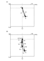
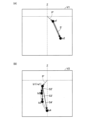
- FIG. 3 is a diagram illustrating a screen used in composite image output processing.
- FIG. 7 is a diagram illustrating steps S5 and S7 of composite image output processing.
- FIG. 7 is a diagram illustrating step S8 of composite image output processing.
- 7 is a diagram illustrating steps S12 to S17 of composite image output processing.
- FIG. FIG. 6 is a diagram illustrating step S18 of composite image output processing.
- FIG. 3 is a diagram illustrating calculation of the length of a vector.
- 7 is a diagram illustrating steps S19 to S21 of composite image output processing.
- FIG. 7 is a diagram illustrating an example of an ultrasound image displayed on a canvas after step S21 of the composite image output process.
- FIG. 6 is a diagram illustrating step S22 of composite image output processing.
- FIG. 7 is a diagram illustrating step S23 of composite image output processing.
- 7 is a diagram illustrating steps S24 to S28 of composite image output processing.
- FIG. FIG. 7 is a diagram illustrating step S30 of composite image output processing.
- FIG. 7 is a diagram illustrating step S30 of composite image output processing.
- FIG. 3 is a diagram showing an example of a composite image.
- FIG. 2 is an explanatory diagram illustrating the configuration of a surgical support system according to a second embodiment.
- 7 is a flowchart illustrating an example of composite image output processing according to the second embodiment.
- FIG. 7 is a diagram illustrating composite image output processing according to the second embodiment.
- FIG. 7 is a diagram illustrating step S18A of composite image output processing in the second embodiment.
- FIG. 3 is an explanatory diagram illustrating the configuration of a surgical support system according to a third embodiment.
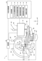
- FIG. 1 is an explanatory diagram illustrating the configuration of a surgical support system 1.
- the surgical support system 1 is a system that supports examinations and treatments.
- the surgical support system 1 includes a surgical support device 10, a blood vessel imaging device 20 having an FPD (Flat Panel Detector), a display device 30, a table 40, and an operation unit 50.
- the surgical support system 1 of the present embodiment includes a surgical support device 10 to be described later, so that the surgical support system 1 can convert the captured image (hereinafter also referred to as an "angiographic image") of a target blood vessel by an FPD into an angioimage.
- a true lumen image representing the true lumen at a corresponding position and posture can be generated, and a composite image obtained by combining the angio image and the true lumen image can be displayed.
- target blood vessel means a blood vessel that is the target of examination or treatment, but the surgical support system 1 is applicable not only to the vascular system but also to the lymph gland system, biliary tract system, urinary tract system, respiratory tract system, and digestive system. It may be used within the lumen of a living body, such as the system, secretory glands, and reproductive organs.
- FIG. 1 mutually orthogonal XYZ axes are illustrated.
- the X axis corresponds to the width direction of the blood vessel imaging device 20
- the Y axis corresponds to the height direction of the blood vessel imaging device 20
- the Z axis corresponds to the depth direction of the blood vessel imaging device 20.
- the direction in which the head 92 of the patient (FIG. 1: human body 90) is located is also simply referred to as the "Z-axis direction" and simply expressed as "Z”.
- a three-dimensional space formed by three-dimensional coordinates (XYZ coordinates) consisting of the X, Y, and Z axes is called an XYZ three-dimensional space. Note that the origin O of the XYZ three-dimensional space (XYZ coordinates) is the position of the heart 91 of the human body 90.
- the surgical support device 10 In the composite image output process described below, the surgical support device 10 generates a true lumen image representing the true lumen at a position and posture corresponding to the angio image captured by the FPD, and combines the angio image and the true lumen image. Output the composite image.
- the surgical support device 10 includes a CPU, a ROM, and a RAM, and the CPU executes a computer program stored in the ROM to control the main control unit 11, the angio image acquisition unit 12, and the ultrasound image acquisition unit 12.
- the functions of an image acquisition section 13, a true lumen information acquisition section 14, a true lumen image generation section 15, and an image composition section 16 are realized.
- the surgical support device 10 is electrically connected to each of the control section 29, display device 30, and operation section 50 of the blood vessel imaging device 20.
- the main control unit 11 transmits and receives information to and from the control unit 29, display device 30, and operation unit 50 of the blood vessel imaging device 20, and controls the entire surgical support device 10. Further, the main control unit 11 controls the entire composite image output process, which will be described later.
- the angio image acquisition unit 12 acquires a first angio image and a second angio image from the blood vessel imaging device 20 in the composite image output process.
- the "first angio image” is an angio image captured by arranging the FPD at an arbitrary imaging position.
- the imaging position of the FPD when the first image is acquired is also referred to as the "first position.”
- the “second angio image” is an angio image captured with the FPD at an arbitrary imaging position different from the first position.
- the imaging position of the FPD at which the second image is acquired is also referred to as a "second position.” Details of the first and second angio images and the first and second positions will be described later.
- the process (step) performed by the angio image acquisition unit 12 is also referred to as an angio image acquisition process (step).
- the ultrasound image acquisition unit 13 acquires, from the imaging sensor 300 (FIG. 3), an ultrasound image of the inside of the target blood vessel imaged by the imaging sensor 300 in the composite image output process. Details will be described later.
- the process (step) performed by the ultrasound image acquisition unit 13 is also referred to as an ultrasound image acquisition process (step).
- the true lumen information acquisition unit 14 uses the position information of the first position, the first angio image, the position information of the second position, the second angio image, and the ultrasound image. Three-dimensional positional information (positional information in the XYZ three-dimensional space) of the true lumen existing in the target blood vessel is acquired. Details will be described later.
- the process (step) executed by the true lumen information acquisition unit 14 is also referred to as a true lumen information acquisition process (step).
- the true lumen image generation unit 15 In the composite image output process, the true lumen image generation unit 15 generates an image corresponding to the angio image captured by the FPD located at an arbitrary imaging position (hereinafter also referred to as "first imaging position"). A true lumen image representing the true lumen at the position and posture is generated. In addition, when the FPD is moved to an arbitrary imaging position different from the first imaging position (hereinafter also referred to as "second imaging position") and imaging is performed by the FPD, the true lumen image generation unit 15 A true lumen image representing the true lumen at a position and posture corresponding to the angio image is regenerated for the angio image taken at the imaging position.
- first imaging position and the second imaging position are arbitrary positions different from the above-mentioned first position and second position, that is, arbitrary positions where the operator intends to confirm the target blood vessel and device. means location.
- first imaging position and the second imaging position may be the same as the first and second positions described above. Details will be described later.
- the process (step) executed by the true lumen image generation section 15 is also referred to as a true lumen image generation process (step).
- the image synthesis unit 16 In the composite image output process, the image synthesis unit 16 generates a composite image obtained by combining the angio image captured by the FPD placed at the first imaging position and the true lumen image generated by the true lumen image generation unit 15. generated and displayed on the display device 30. Furthermore, the image synthesis unit 16 regenerates a composite image by combining the angio image captured by the FPD placed at the second imaging position and the true lumen image regenerated by the true lumen image generation unit 15. , to be displayed on the display device 30. Details will be described later.
- the process (step) executed by the image composition unit 16 is also referred to as an image composition process (step).
- the blood vessel imaging device 20 has an FPD and acquires an image (angiography image) by acquiring X-rays that have passed through the human body and converting them into digital signals.
- the blood vessel imaging device 20 includes a first FPD 21, a first X-ray tube device 22, a first C-arm 23, a first support section 24, a second FPD 25, a second X-ray tube device 26, a second C-arm 27, and a first C-arm 23. It has two support parts 28 and a control part 29.
- the first FPD 21 includes an X-ray flat detector, converts the X-rays incident from the first X-ray tube device 22 into electrical signals, performs A/D (analog/digital) conversion, and generates an X-ray image. do.
- the first X-ray tube device 22 receives a high voltage output from an X-ray high voltage device (not shown) and irradiates an X-ray beam. As shown by the thick broken line extending in the Y-axis direction in FIG. 1, the X-ray beam irradiated from the first X-ray tube device 22 enters the first FPD 21 via the human body 90.
- the first C-arm 23 is a C-shaped arm (supporting tool) that fixes the first FPD 21 and the first X-ray tube device 22 at opposing positions.
- the first support portion 24 rotatably supports the first C-arm 23. That is, the first FPD 21 and the first X-ray tube device 22 can be moved to any imaging position around the human body 90 lying on the bed 41 while being fixed at opposing positions by the first C-arm 23.
- first FPD 21 and the first X-ray tube device 22 fixed to the first C-arm 23 will also be simply referred to as "first FPD 21.”
- the configuration of the second FPD 25 is similar to that of the first FPD 21.
- the configuration of the second X-ray tube device 26 is similar to that of the first X-ray tube device 22.
- the second C-arm 27 is a C-shaped arm (supporting tool) that fixes the second FPD 25 and the second X-ray tube device 26 in opposing positions.
- the second support part 28 rotatably supports the second C-arm 27.
- the second FPD 25 and the second X-ray tube device 26 can be moved to any imaging position around the human body 90 while being fixed at opposing positions by the second C-arm 27.
- the second FPD 25 and the second X-ray tube device 26 fixed to the second C-arm 27 will also be simply referred to as "second FPD 25.”
- the second FPD 25 is generally arranged in the normal direction of the first FPD 21.
- the first FPD 21 when the first FPD 21 is set at the imaging position in the front direction of the human body 90 (the vertical direction of the human body 90, the longitudinal direction of the human body 90), the second FPD 25 is positioned in the horizontal direction of the human body 90 (the vertical direction of the human body 90). (lateral direction) imaging position.
- the blood vessel imaging device 20 may also be simply referred to as an "FPD" or "FPD device.”
- the control unit 29 is configured to include a CPU, ROM, and RAM, and the CPU controls the entire blood vessel imaging device 20 by executing a computer program stored in the ROM.
- the control section 29 is electrically connected to each of the first FPD 21, the second FPD 25, the first support section 24, the second support section 28, the display device 30, the table 40, and the operation section 50.
- the control unit 29 causes the display device 30 to display the X-ray images generated by the first FPD 21 and the second FPD 25.
- the control section 29 drives the first support section 24 to rotate the first C-arm 23 and drives the second support section 28 to rotate the second C-arm 27 in accordance with the operation from the operation section 50 .
- the control unit 29 changes the height of the bed 41 by expanding and contracting the extendable part 42 and changes the position of the bed 41 by moving the table 40 in the Z-axis direction according to the operation from the operation part 50. .
- the display device 30 is connected to the surgery support device 10 and the control unit 29 of the blood vessel imaging device 20, and functions as an output interface for the surgery support device 10 and the blood vessel imaging device 20.
- the display device 30 includes a monitor 31 and an arm 32.
- the monitor 31 is a "display unit” configured by a well-known means such as a liquid crystal display, smart glasses, or a projector.
- the arm 32 supports and fixes the monitor 31.
- the table 40 is a stand on which the human body 90 is placed near the first FPD 21 and the second FPD 25.
- the table 40 has a bed 41, an extendable portion 42, and leg portions 43.
- the bed 41 includes a mattress on which the human body 90 lies.
- the bed 41 is supported by the table 40 so as to be movable in the Z-axis direction.
- the extensible portion 42 is configured to be able to change the height of the bed 41 by expanding and contracting in the Y-axis direction.
- the leg portions 43 support the bed 41 and the extendable portion 42. As shown by the broken line in FIG.
- the human body 90 is placed facing upward on the bed 41, with the head 92 placed on the side closer to the first FPD 21 and the second FPD 25, and the feet 93 placed on the side farther from the first FPD 21 and second FPD 25. is laid to rest. In this way, it is easy to obtain an image of the target blood vessel in the heart 91 using the first FPD 21 and the second FPD 25.
- the operation unit 50 is connected to the surgery support device 10 and the control unit 29 of the blood vessel imaging device 20, and functions as an input interface for the surgery support device 10 and the blood vessel imaging device 20.
- the operation unit 50 is an "input unit" that includes a touch panel, an operation button, an operation lever, an operation switch, a keyboard, a mouse, a voice input unit, a foot switch, and other known means. In the illustrated example, the operation unit 50 is fixed to the table 40.
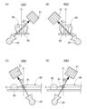
- FIG. 2 is a diagram illustrating the imaging position of the first FPD 21.
- FIG. 2(A) is a diagram for explaining LAO
- FIG. 2(B) is a diagram for explaining RAO.
- LAO Left Anterior Oblique view
- RAO Light Anterior Oblique view
- FIG. 2(C) is a diagram for explaining CRA
- FIG. 2(D) is a diagram for explaining CAU.
- the case where the first FPD 21 is positioned above the human body 90 is called CRA (CRAnial).
- CAU the case where the first FPD 21 is positioned below the human body 90 is called CAU (CAUdal). That is, the "imaging position of the first FPD 21" is specified by the combination of the horizontal position (A1) and the vertical position (A2) shown below. (A1) LAO or RAO, angle ⁇ 1 from center O of human body 90, (A2) CRA or CAU and the angle ⁇ 2 from the center O of the human body 90.
- the center O of the human body 90 is the position of the heart 91 of the human body 90 (the position of the origin O in the XYZ three-dimensional space).
- the imaging position of the first FPD 21 is (RAO28 CRA5)
- the first FPD 21 is located at a position of 28 degrees to the right of the human body 90 and at a position of 5 degrees to the upper side of the human body 90. do.
- FIG. 3 is a diagram illustrating the target blood vessel 100 and the device used.
- FIG. 3(A) is a diagram showing a longitudinal section of the target blood vessel 100
- FIG. 3(B) is a diagram showing a portion of the target blood vessel 100 surrounded by a broken line rectangle in FIG. 3(A) viewed from above. be.
- FIG. 3A shows a target blood vessel 100, a CTO 101 generated in the target blood vessel 100, a false lumen 102 formed on or under the intima of the target blood vessel 100, and a true lumen 103.
- the false lumen 102 means all dissection lumens other than the true lumen 103 formed by the medical device.
- the true lumen 103 does not necessarily extend linearly, but may meander.
- the operator in order to guide the guide wire 500 into the true lumen 103, the operator needs to direct the distal end of the guide wire 500 toward the bottom of the page.
- the FPD can only obtain a fluoroscopic image in a certain cross section, depending on the imaging position of the FPD, it is not possible to capture a part of the meandering true lumen 103 in the angio image as shown in FIG. 3(A).
- the surgical support apparatus 10 of the present embodiment can solve such a problem because it generates and displays a true lumen image representing an image of the true lumen through composite image output processing, which will be described later.
- the surgical support system 1 uses an imaging sensor 300 and a guide wire 500 shown in FIG. 3(A).
- the imaging sensor 300 is an ultrasonic sensor that acquires an ultrasonic image inside the target blood vessel 100.
- the imaging sensor 300 has an elongated outer shape and includes a transducer 301 at the tip.
- the transducer 301 is an ultrasonic probe (an ultrasonic transducer, a piezoelectric material, an ultrasonic transmitting/receiving element, an ultrasonic element, ).
- the imaging sensor 300 acquires an ultrasound image of the inside of the target blood vessel 100 around the transducer 301 while moving back and forth within the lumen of the sensor catheter 200.
- the transducer 301 rotates around the central axis of the transducer 301 (hereinafter also referred to as the transducer axis) that extends in the longitudinal direction of the image sensor 300, and is perpendicular to the transducer axis (360 degrees of the transducer axis).
- An ultrasound image of the inside of the target blood vessel 100 is acquired.
- the guide wire 500 is a medical device having an elongated outer shape.
- the guide wire 500 may be a plasma guide wire that includes an electrode at its tip and performs ablation of living tissue using a plasma flow.
- the wire catheter 400 may be configured to include the other electrode at the distal end.
- the guide wire 500 may be a penetrating guide wire that has a pointed portion at the tip and penetrates living tissue using the pointed portion, or may be a delivery guide wire that does not have a pointed portion. good.
- the guide wire 500 is housed in the lumen of the wire catheter 400, and the distal end portion of the guide wire 500 projects outward from the distal end portion 401 of the wire catheter 400.
- FIGS. 4 and 5 are flowcharts illustrating an example of composite image output processing.
- the composite image output process can be started at any timing, such as when the surgical support device 10 is powered on, a predetermined application is started, the blood vessel imaging device 20 is powered on, or the like.
- a case where an angio image is obtained using the first FPD 21 will be exemplified.
- the angio image may be acquired using the second FPD 25.
- the portion described as "first FPD 21" may be replaced with "second FPD 25" for processing.
- the imaging sensor 300 is simply referred to as a "sensor”
- the angio image is simply referred to as an "image”.
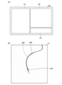
- FIG. 6 is a diagram illustrating a screen used in composite image output processing.
- FIG. 6(A) is a diagram showing the configuration of the operation screen OS
- FIG. 6(B) is a diagram showing an example of the first angio image V1.
- the true lumen information acquisition unit 14 proceeds with the processing while providing operational guidance to the operator.
- the true lumen information acquisition unit 14 causes the display device 30 to display an operation screen OS as shown in FIG. 6(A), and performs various operations using this operation screen OS. Display information.
- the operation screen OS includes an operation button display area A1 in which buttons for performing various operations are arranged, a canvas A2, and a guidance display area A3 in which various guidance messages are displayed.
- the canvas A2 is an area for displaying angio images sequentially acquired by the first FPD 21 and ultrasound images acquired by the imaging sensor 300. Note that in the composite image output process, the true lumen information acquisition unit 14 advances each step while updating the angio image displayed on the canvas A2 of the operation screen OS.
- the operation screen OS is just an example and can be changed in various ways.
- the guidance display area A3 of the operation screen OS may be omitted and guidance may be provided by voice.
- the guide display area A3 of the operation screen OS may be omitted, and a button with an item name attached (for example, a button labeled "first landmark placement" in the case of step S5) may be placed in the operation button display area A1. This may be used instead of guidance.
- step S1 the true lumen information acquisition unit 14 guides the first FPD 21 to prepare for imaging. Following the guidance, the operator prepares for imaging using the first FPD 21. Specifically, as shown in FIG. 1, the human body 90 is laid down on the bed 41, and the power of the blood vessel imaging device 20 is turned on.
- step S2 the true lumen information acquisition unit 14 guides the imaging sensor 300 to prepare for imaging. Following the guidance, the surgeon prepares for imaging using the imaging sensor 300. Specifically, as shown in FIG. 3A, an imaging sensor 300 and a guide wire 500 are inserted into a blood vessel of a human body 90, and the transducer 301 of the imaging sensor 300 and the distal end of the guide wire 500 It is delivered so as to be located near the CTO 101 of the blood vessel 100.
- step S3 the true lumen information acquisition unit 14 guides the first FPD 21 to move to the first position and capture an X-ray image. Following the guidance, the operator moves the first FPD 21 to the first position and captures an X-ray image of the target blood vessel 100, thereby obtaining a first angio image V1.
- the first position can be any position (RAO XX CRA XX: X is any natural number).
- the true lumen information acquisition unit 14 may automatically move the first FPD 21 to the first position and perform imaging.
- the angio image acquisition unit 12 acquires the captured first angio image V1 from the blood vessel imaging device 20. As shown in FIG.
- the first angio image V1 includes an image of the imaging sensor 300, an image of the guide wire 500, and an image of the target blood vessel 100 through which the imaging sensor 300 and the guide wire 500 are inserted ( (not shown).
- the imaging sensor 300 is illustrated with a broken line
- the guide wire 500 is illustrated with a solid line.
- the first angio image V1 includes an image of the target blood vessel 100.
- the first angio image V1 only needs to include the image of the imaging sensor 300 and the image of the guide wire 500, and does not need to include the image of the target blood vessel 100.
- the "image of the target blood vessel 100" means an image of the outline of the target blood vessel 100.
- step S4 the true lumen information acquisition unit 14 displays the first angio image V1 on the canvas A2, and positions the image of the transducer 301 (see FIG. 3) among the images of the imaging sensor 300 at the center of the canvas A2.
- the position of the first angio image V1 is adjusted so that
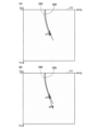
- FIG. 7 is a diagram illustrating steps S5 and S7 of the composite image output process.
- FIG. 7(A) is a diagram showing the state of the canvas A2 in step S5
- FIG. 7(B) is a diagram showing the state of the canvas A2 in step S7.
- a square or rectangular canvas A2 has an origin Oc at the top left corner of the page, and XcYc coordinates, which are two-dimensional coordinates consisting of an Xc axis extending to the right of the page and a Yc axis extending downwards of the page. have.
- the two-dimensional space formed by the XcYc coordinates is called the XcYc two-dimensional space.
- the negative direction of the Yc axis is the direction in which the head 92 of the human body 90 (see FIG. 1) is located.
- the true lumen information acquisition unit 14 guides the user to place the first mark a1 on the image of the transducer 301 of the imaging sensor 300 in the first angio image V1 displayed on the canvas A2.
- the surgeon places the first mark a1 on the first angio image V1 on the canvas A2, as shown in FIG. 7(A).
- the placement of the first mark a1 can be achieved, for example, by clicking or tapping the intended position on the image of the canvas A2.
- the actual position (position in the XYZ coordinates) of the transducer 301 inside the target blood vessel 100 is assumed to be P1. .
- step S6 the true lumen information acquisition unit 14 guides the user to acquire the ultrasound image IV1 using the imaging sensor 300 while maintaining the position of the imaging sensor 300.
- the operator acquires an ultrasound image IV1 from the imaging sensor 300 without moving the imaging sensor 300 from the position shown in FIG. 7(A).
- the ultrasound image acquisition unit 13 acquires the captured ultrasound image IV1 from the imaging sensor 300, and stores the ultrasound image IV1 in the storage unit inside the surgery support device 10. That is, the ultrasound image acquisition unit 13 acquires an ultrasound image IV1 when the transducer 301 is located at P1 within the target blood vessel 100.
- the first angio image V1 acquired in step S3 includes the target blood vessel 100, the image of the imaging sensor 300 placed at the first landmark position (first mark a1) in the target blood vessel 100, and the target blood vessel 100 (an arbitrary position different from the first mark a1).
- the ultrasound image IV1 acquired in step S6 also includes the target blood vessel 100 and the guide wire 500 placed at a second landmark position (an arbitrary position different from the first landmark a1) within the target blood vessel 100. , will be included.
- step S7 the true lumen information acquisition unit 14 advances the imaging sensor 300 within a range that can be regarded as a straight line, and then guides the imaging sensor 301 to place the second mark a2 on the transducer 301.
- "straight line” means that the trajectory of the transducer 301 when moving inside the sensor catheter 200 is a straight line.
- the operator advances the imaging sensor 300 by a range (distance) that can be regarded as a straight line, and then places the second landmark a2 on the first angio image V1 on the canvas A2. Deploy.
- the actual position (position in the XYZ coordinates) of the transducer 301 inside the target blood vessel 100 is Pe. .
- FIG. 8 is a diagram illustrating step S8 of the composite image output process.
- FIGS. 8A and 8B are diagrams illustrating calculation of BNV, which will be described later.
- FIG. 8(C) is a diagram showing the relationship between a first angio image V1 at a first position and a second angio image V2 at a second position, which will be described later.
- FIG. 8(D) is a diagram showing the first angio image V1 at the first position.
- FIG. 8(E) is a diagram showing the second angio image V2 at the second position.
- step S8 the true lumen information acquisition unit 14 calculates the BNV using the first mark a1, the second mark a2, and the first position in the first angio image V1 on the canvas A2. Specifically, as shown in FIG. 8A, the true lumen information acquisition unit 14 generates a vector (a vector representing the trajectory of the transducer 301 that can be regarded as a straight line) having the first landmark a1 as the starting point and the second landmark a2 as the ending point. ) is the first shaft axis vector Ie' of the imaging sensor 300, and the vector representing the first view, which is the imaging direction of the first FPD 21 placed at the first position with respect to the heart 91 (see FIG. 1), is the first view vector Vw1.
- a vector a vector representing the trajectory of the transducer 301 that can be regarded as a straight line
- the BNV for the plane W including the first shaft axis vector Ie' and the first view vector Vw1 is calculated. Furthermore, since the plane W is a plane that includes the first shaft axis vector Ie', the distance from P1 (corresponding to the first landmark a1) to Pe (corresponding to the second landmark a2) of the transducer 301 in the XYZ three-dimensional space is It can be said that it is the plane on which the orbit lies.
- BNV means the imaging direction perpendicular to the plane W, as shown in FIG. 8(A). That is, BNV means an imaging direction in which a second angio image V2 perpendicular to the first angio image V1 can be obtained.
- the vector representing the second view be a second view vector Vw2.
- the true lumen information acquisition unit 14 obtains a numerical value RL val representing LAO or RAO, which is positional information of the first FPD 21 at the first position (also simply referred to as "positional information of the first position"), and a numerical value CC representing CRA or CAU.
- " ⁇ " and “ ⁇ ” are variables for displaying the first view vector Vw1 in polar coordinates.
- CW means “clockwise”
- CCW means "counterclockwise”.
- the true lumen information acquisition unit 14 calculates the orthogonal coordinates of the second view vector Vw2 by substituting the calculated ⁇ , ⁇ , and ⁇ into equation (2).
- the true lumen information acquisition unit 14 converts the orthogonal coordinates (x, y, z) of the second view vector Vw2 into polar coordinates (r, ⁇ , ⁇ ) using equation (3).
- the true lumen information acquisition unit 14 obtains a numerical value RL val representing LAO or RAO at the second position and a numerical value CC val representing CRA or CAU from the polar coordinates (r, ⁇ , ⁇ ) of the second view vector Vw2. calculate.
- the imaging sensor 300 is in the posture shown in FIG. 8(C) within the target blood vessel 100.
- the imaging sensor 300 was advanced within a range that can be regarded as a straight line, so the first angio image V1 is an image obtained from the first view in the direction in which the imaging sensor 300 appears to be a straight line, that is, the first position. I can say that there is. Therefore, the imaging sensor 300 is captured in a straight line in the first angio image V1, as shown in the hatched images in FIGS. 8(C) and 8(D).
- the second angio image V2 obtained from the second view at the second position is perpendicular to the first angio image V1.
- This can be said to be an image acquired from a direction in which the imaging sensor 300 (orbit of the transducer 301) appears curved. Therefore, the imaging sensor 300 is captured in a curved shape in the second angio image V2, as shown in the dot-hatched images in FIGS. 8(C) and 8(E).
- step S9 the true lumen information acquisition unit 14 guides the transducer 301 of the imaging sensor 300 to return to the position of the first landmark a1. Following the guidance, the operator pulls the transducer 301 back to the position of the first landmark a1. That is, the operator pulls the transducer 301 inside the target blood vessel 100 back from the position Pe in the XYZ coordinates to P1.
- step S10 the true lumen information acquisition unit 14 guides the first FPD 21 to move to the second position corresponding to the BNV calculated in step S8 and to capture an X-ray image.
- the operator moves the first FPD 21 to the second position and captures an X-ray image of the target blood vessel 100, thereby obtaining a second angio image V2.
- the true lumen information acquisition unit 14 may automatically move the first FPD 21 to the second position and perform imaging.
- the angio image acquisition unit 12 acquires the captured second angio image V2 from the blood vessel imaging device 20. As will be described later in FIG.
- the second angio image V2 includes an image of the imaging sensor 300, an image of the guide wire 500, an image of the imaging sensor 300 and the guide wire, which are captured from a different direction from the first angio image V1.
- 500 is inserted into the target blood vessel 100 (not shown).
- the second angio image V2 includes an image of the target blood vessel 100.
- the second angio image V2 only needs to include the image of the imaging sensor 300, and does not need to include the image of the target blood vessel 100 or the image of the guide wire 500.
- step S11 the true lumen information acquisition unit 14 displays the second angio image V2 on the canvas A2, and displays the second angio image so that the image of the transducer 301 of the imaging sensor 300 is located at the center of the canvas A2. Adjust the position of V2.
- FIG. 9 is a diagram illustrating steps S12 to S17 of the composite image output processing.
- FIG. 9 shows an example of the second angio image V2 on the canvas A2.
- the true lumen information acquisition unit 14 guides the user to place the first mark b1 on the image of the transducer 301 of the imaging sensor 300 in the second angio image V2 displayed on the canvas A2.
- the surgeon places the first mark b1 on the second angio image V2 on the canvas A2.
- the placement of the first mark b1 can be achieved, for example, by clicking or tapping the intended position on the image of the canvas A2.
- step S13 the true lumen information acquisition unit 14 substitutes 2 for the variable n used in the composite image output process.
- n is a natural number.
- step S14 the true lumen information acquisition unit 14 advances the imaging sensor 300 by an arbitrary distance and guides the imaging sensor 300 to place the second mark b2 on the transducer 301. Following the guidance, the operator advances the imaging sensor 300 and then places the second mark b2 on the second angio image V2 on the canvas A2. Note that on the second angio image V2, when the image of the transducer 301 is located at the second mark b2 of the XcYc coordinates on the canvas A2, the actual position (position in the XYZ coordinates) of the transducer 301 within the target blood vessel 100 is assumed to be P2. .
- the true lumen information acquisition unit 14 guides the user to acquire the ultrasound image IV2 using the imaging sensor 300 while maintaining the position of the imaging sensor 300. Following the guidance, the operator acquires an ultrasound image IV2 from the imaging sensor 300 without moving the imaging sensor 300.
- the ultrasound image acquisition unit 13 acquires the captured ultrasound image IV2 from the imaging sensor 300, and stores the ultrasound image IV2 in the storage unit inside the surgery support device 10. That is, the ultrasound image acquisition unit 13 acquires an ultrasound image IV2 when the transducer 301 is located at P2 within the target blood vessel 100.
- the true lumen information acquisition unit 14 adds 1 to the variable n.
- step S17 the true lumen information acquisition unit 14 arranges the landmarks on the second angio image V2 (step S14) and acquires an ultrasound image at the location of the landmarks (step S15) with the desired number of landmarks. Determine whether or not the task has been completed.
- step S17: YES the true lumen information acquisition unit 14 shifts the process to step S18. If the variable n has not reached the target number of landmarks (step S17: NO), the true lumen information acquisition unit 14 shifts the process to step S14 and repeats the above-described process. As a result, as shown in FIG.
- each An ultrasound image IVn corresponding to the location of the n-th landmark bn is acquired (step S15).
- the range in which the imaging sensor 300 is pushed on the second angio image V2 is the range in which the imaging sensor 300 can be regarded as a straight line on the first angio image V1, that is, from the first landmark a1 to the second landmark a2 (target (In the blood vessel 100, from position P1 to Pe).
- FIG. 10 is a diagram illustrating step S18 of the composite image output process.
- FIG. 10(A) is a diagram showing each point on the first angio image V1 displayed on the canvas A2
- FIG. 10(B) is a diagram showing each point on the second angio image V2 displayed on the canvas A2.
- FIGS. 10A and 10B which are diagrams showing the above, the upper side of the page is oriented toward the Z axis of the XYZ coordinates (FIG. 1: the direction in which the head 92 of the human body 90 is located). That is, the negative direction of the Yc axis of the canvas A2 is the direction in which the head 92 of the human body 90 in FIG. 1 is located.
- the Yc' axis is a straight line parallel to the Yc axis.
- step S18 the true lumen information acquisition unit 14 obtains each coordinate in the XcYc coordinates of the first landmark a1 and the second landmark a2 in the first angio image V1 displayed on the canvas A2, and the first landmark b1 in the second angio image V2.
- Each coordinate in the XcYc coordinates of the n-th landmark bn is used to calculate the following (B1) and (B2).
- the transducer axis vectors T1 to Tn are the transducer axes (of the imaging sensor 300) when the transducer 301 is located at positions P1 to Pn in the target blood vessel 100. This is a vector of the central axis of the transducer 301 extending in the longitudinal direction.
- the transducer axis vector when the transducer 301 is located at the positions P1 to Pn can be said to be the tangential vector at the positions P1 to Pn on the trajectory of the transducer 301.
- the first angio image V1 and the second angio image V2 displayed on the canvas A2 are images of the imaging sensor 300 captured from different angles.
- the first shaft axis vector Ie' is a vector extending from the first mark a1 to the second mark a2 on the first angio image V1.
- the second shaft axis vector P2' is a vector extending from the first mark b1 to the second mark b2 on the second angio image V2
- the second shaft axis vector Pn' is a vector extending from the first mark b1 to the nth mark is a vector extending to bn.
- the tangent vector T' on the trajectory of the transducer 301 that has passed the first landmark a1 and the second landmark a2 is on the first shaft axis vector Ie'.
- the orientation of "(B2) transducer axis vectors T1 to Tn of the transducer 301 of the imaging sensor 300" is determined by the inclination ⁇ of the shaft axis vector Ie' with respect to the Yc axis in the first angio image V1 and the inclination ⁇ of the shaft axis vector Ie' in the first angio image V1 with respect to the Yc axis.
- the tangent vector T1' in the second angio image V2 is the tangent vector at the first landmark b1 on the trajectory of the transducer 301 extending from the first landmark b1 to the n-th mark bn.
- the tangential vector Tn' is the tangential vector at the n-th landmark bn on the trajectory of the transducer 301.
- first and second angio images V1 and V2 taken at different first and second positions, respectively, a first view vector Vw1 representing the imaging direction of the first FPD 21 at the first position and a transducer reflected on the first angio image V1 are obtained.
- Details of the method for determining the direction of the vector of an object located on a straight line intersecting the plane defined by the second shaft axis vectors P2' to Pn' are disclosed in International Application No.
- PCT/JP2021/034980 In the international application PCT/JP2021/034980, a straight line where the H2 plane and the S plane intersect is defined using the blood vessel existence plane H2 seen from the first position and the blood vessel existence plane S seen from the second position. , the "blood vessel axis vector", which is the straight line, is calculated.
- a first view vector Vw1 representing the imaging direction of the first FPD 21 at the first position
- a first shaft axis vector Ie' representing the trajectory of the transducer 301 reflected on the first angio image V1.
- the plane defined by the vector corresponds to the H2 plane, and is determined by the second view vector Vw2 representing the imaging direction of the first FPD 21 at the second position and the second shaft axis vectors P2' to Pn' reflected on the second angio image V2.
- the defined plane corresponds to the S plane, and the position vectors P2 to Pn calculated in the above (B1) may be calculated as corresponding to the blood vessel axis vector. Further, the transducer axis vectors T1 to Tn calculated in the above (B2) can be similarly calculated as being equivalent to the blood vessel axis vector.
- FIG. 11 is a diagram illustrating calculation of the lengths of the position vectors P2 to Pn of the transducer 301. Specifically, FIG. 11 explains, as an example, calculation of the length of the position vector P2 of the transducer 301 when the transducer 301 moves from the starting point (reference point) P1 to the ending point P2 in the target blood vessel 100. It is a diagram. The length of the position vector Pn can be similarly calculated.
- vector Vw2 is a second view vector Vw2 (see FIG. 8(A)) representing the imaging direction when the first FPD 21 is in the second position.
- b1 is the first mark b1 on the second angio image V2, and is the position of the transducer 301 on the second angio image V2 when the transducer 301 is located at the starting point P1.
- b2 is the second mark b2 on the second angio image V2, and is the position of the transducer 301 on the second angio image V2 when the transducer 301 is located at the end point P2.
- Vector P2' is the second shaft axis vector P2' of the transducer 301 on the second angio image V2, and is an orthogonal projection vector of the position vector P2 of the transducer 301 onto the second angio image V2.
- ⁇ is an angle formed by the second view vector Vw2 and the position vector P2.
- step S18 the true lumen information acquisition unit 14 calculates the length of the above-mentioned "(B1) position vectors P2 to Pn of the transducer 301" using the following equation (4).
- ⁇ can be calculated using the first equation of equation (4) based on the inner product formula of vectors.
- the length of the second shaft axis vector P2' can be calculated from the coordinates b1 and b2 in the XcYc coordinates of the canvas A2, the length of the position vector P2 can be derived from the second equation of equation (4).
- Vw2 ⁇ P2 represents the inner product of the second view vector Vw2 and the position vector P2
- P2 and P2" ''' represents the length of the position vector P2 and the second shaft axis vector P2', respectively.
- FIG. 12 is a diagram illustrating steps S19 to S21 of the composite image output process.
- FIG. 12(A) is a diagram showing an example of an angio image V ⁇ when the first FPD 21 is placed at position ⁇ .
- FIG. 12(B) is a diagram showing the relationship among the first FPD 21, the imaging sensor 300, and the guide wire 500 when the first FPD 21 is placed at the position ⁇ .
- the angio image V ⁇ is an angio image captured by the first FPD 21 located at a position ⁇ where the transducer 301 and the guide wire 500 appear to overlap when the transducer 301 is located at P1 in the target blood vessel 100. .
- step S20 the true lumen information acquisition unit 14 obtains an ultrasound image IV1 (an ultrasound image when the transducer 301 is located at the first landmark b1 on the second angio image V2, that is, an ultrasound image when the transducer 301 is located inside the target blood vessel 100).
- An ultrasound image obtained when the camera is positioned at P1) is displayed on canvas A2.
- step S21 the true lumen information acquisition unit 14 performs orientation calibration processing (directions from the transducer 301 to the guide wire 500 in the XYZ three-dimensional space and the direction from the transducer 301 to the guide wire 500 in the ultrasound image IV1 displayed in the XcYc two-dimensional space of the canvas A2). (a process of associating the direction toward the wire 500).
- the true lumen information acquisition unit 14 acquires the position ⁇ of the first FPD 21 in step S19.
- a vector representing the imaging direction of the first FPD 21 placed at position ⁇ with respect to the heart 91 is defined as a view vector Vw ⁇ .
- the true lumen information acquisition unit 14 calculates a view vector Vw ⁇ from the acquired position ⁇ of the first FPD 21. As shown in equation (5), the true lumen information acquisition unit 14 uses the cross product of the transducer axis vector T1 of the imaging sensor 300 at the position P1 in the target blood vessel 100 calculated in (B2) above and the view vector Vw ⁇ . Calculate the rotation axis R (r1, r2, r3).
- the true lumen information acquisition unit 14 converts the transducer axis vector T1 of the transducer 301 calculated in (B2) above by 90 degrees around the rotation axis R obtained from Equation (5).
- Equation (7) is a matrix representation of Rodriguez's rotation formula shown in Equation (6).
- FIG. 13 is a diagram showing an example of the ultrasound image IV1 displayed on the canvas A2 in step S20.
- the ultrasound image IV1 is a target blood vessel in a direction perpendicular to the transducer axis T1 (360° circumferential direction of the transducer axis T1) when the transducer 301 is at the first landmark b1 of the second angio image V2.
- This is an ultrasound image of the inside of 100.
- the ultrasound image IV1 includes an image of the guide wire 500 (a portion that appears relatively white compared to the surrounding area) and an image of the true lumen 103 (a portion that appears relatively black compared to the surrounding area).
- an arrow CV is displayed from the center of the ultrasound image IV1 (that is, the center of the transducer 301) toward the center of the image of the guide wire 500.
- the extending direction of the arrow CV in the XcYc two-dimensional space of the canvas A2 corresponds to the direction of the calculated vector CV1 in the XYZ three-dimensional space.
- step S21 in this way, the direction from the transducer 301 to the guide wire 500 in the XYZ three-dimensional space and the direction from the transducer 301 to the guide wire 500 in the ultrasound image IV1 displayed in the XcYc two-dimensional space of the canvas A2 are determined. An association is made.
- FIG. 14 is a diagram illustrating step S22 of the composite image output process.
- the true lumen information acquisition unit 14 performs size calibration processing (processing that associates the number of pixels of the ultrasound image IV1 displayed on the canvas A2 with the actual dimensions of the ultrasound image IV1).
- a scale SC representing the actual dimensions of the target blood vessel 100 is attached to the ultrasound image IV1.
- the interval between adjacent scale marks is 1 mm.
- the true lumen information acquisition unit 14 draws a line segment from the center of the image of the target blood vessel 100 to a scale located outside the outline of the image of the target blood vessel 100, and draws a line segment on the ultrasound image IV1 of the canvas A2.
- the number of pixels (Fig. 14: x pixel) is measured.
- the true lumen information acquisition unit 14 calculates the number of pixels on the canvas A2 per 1 mm of actual size by calculating the number of measured pixels/the length of the line segment.
- FIG. 15 is a diagram illustrating step S23 of the composite image output process.
- FIG. 15 shows an example of the ultrasound image IV1 displayed on the canvas A2 in step S23.
- the true lumen information acquisition unit 14 calculates a true lumen vector S1 (a vector that is perpendicular to the transducer axis T1 and extends from the transducer 301 to the true lumen 103) in the XYZ three-dimensional space. Specifically, the true lumen information acquisition unit 14 moves an arrow from the center of the ultrasound image IV1 (that is, the center of the transducer 301 of the imaging sensor 300) toward the center of the image of the guide wire 500 in the ultrasound image IV1. Instruct them to submit a CV. As shown in FIG.
- the image of the portion where the transducer 301 is located is located near the center of the ultrasound image IV1, and appears relatively black compared to the surrounding area. Further, since the image of the guide wire 103 appears relatively white compared to the surrounding area, the operator who views the ultrasound image IV1 can grasp the positions of the transducer 301 and the guide wire 500. Following the guidance, the operator draws an arrow CV pointing from the center of the ultrasound image IV1 to the center of the image of the guide wire 500.
- the arrow CV can be drawn by, for example, clicking or tapping the center of the transducer 301 and the center of the image of the guide wire 500 on the ultrasound image IV1 of the canvas A2.
- the vector indicated by arrow CV that is, the vector extending from the center of transducer 301 to the center of guide wire 500 in XcYc coordinates
- the true lumen information acquisition unit 14 also moves an arrow S from the center of the ultrasound image IV1 (that is, the center of the image of the transducer 301 of the imaging sensor 300) toward the center of the image of the true lumen 103 of the ultrasound image IV1. I will guide you to pull it.
- the true lumen 103 appears relatively black on the ultrasound image IV1 compared to the surrounding area, the operator who views the ultrasound image IV1 can grasp the position of the true lumen 103.
- the operator draws an arrow S pointing from the center of the ultrasound image IV1 to the center of the image of the true lumen 103.
- the arrow S can be drawn by, for example, clicking or tapping the center of the transducer 301 and the center of the image of the true lumen 103 on the image of the canvas A2.
- the vector indicated by arrow S that is, the vector extending from the center of transducer 301 to the center of true lumen 103 in XcYc coordinates, be vector s.
- the angle formed by the vector cv and the vector s is assumed to be ⁇ .
- the true lumen information acquisition unit 14 calculates the angle ⁇ formed by the vector cv and the vector s from the vector cv and the vector s in the XcYc coordinates of the canvas A2 using the formula of the inner product of vectors. Then, as shown in equation (8), the true lumen information acquisition unit 14 calculates in step S21 using the transducer axis vector T1 (r1, r2, r3) of the imaging sensor 300 calculated in (B2) above as the rotation axis. By rotating the vector CV1 by ⁇ degrees, the direction of the true lumen vector S1 on the XYZ three-dimensional space is calculated. Note that Equation (9) is a matrix representation of Rodriguez's rotation formula shown in Equation (8).
- the true lumen information acquisition unit 14 also acquires the number a of pixels of the arrow S drawn at the XcYc coordinates of the canvas A2, and the number c of pixels corresponding to the width of the image of the true lumen 103 of the ultrasound image IV1. Note that the number of pixels c of the image of the true lumen 103 may be automatically obtained by image analysis of the ultrasound image IV1, or the width may be specified by the operator. After that, the true lumen information acquisition unit 14 substitutes the acquired number of pixels a and the result b of step S22 (the number of pixels b on the canvas A2 per 1 mm of actual size) into equation (10). , calculate the actual length S length (mm) of the true lumen vector S1.
- the true lumen information acquisition unit 14 substitutes the acquired pixel number c and the result b of step S22 into equation (11), thereby determining the true lumen of the portion corresponding to the true lumen vector S1. Calculate the actual width S width (mm).
- FIG. 16 is a diagram illustrating steps S24 to S28 of the composite image output process.
- the true lumen information acquisition unit 14 substitutes 2 for the variable n used in the composite image output process.
- step S26 the true lumen information acquisition unit 14 calculates the true lumen vector Sn. Specifically, the true lumen information acquisition unit 14 guides the user to draw an arrow S from the center of the ultrasound image IV2 displayed on the canvas A2 toward the image of the true lumen 103 in the ultrasound image IV2. Thereafter, the true lumen information acquisition unit 14 calculates the angle ⁇ d (FIG. 16) formed by the transducer axis vector T1 of the imaging sensor 300 calculated in the above (B2) and the transducer axis vector T2 of the imaging sensor 300. The true lumen information acquisition unit 14 calculates a vector CV2 by rotating the vector CV1 calculated in step S21 by the same amount as the calculated angle ⁇ d.
- the angle ⁇ d FIG. 16
- the rotation axis for rotating the vector CV1 by ⁇ d is calculated by the cross product of the transducer axis vectors T1 and T2.
- the process is the same as step S23.
- the true lumen information acquisition unit 14 acquires the angle ⁇ formed by the arrow CV and the arrow S drawn in the ultrasound image IV2.
- the true lumen information acquisition unit 14 calculates the direction of the true lumen vector S2 by rotating the vector CV2 by ⁇ degrees using the transducer axis vector T2 of the imaging sensor 300 as the rotation axis, as shown in equation (8).
- the true lumen information acquisition unit 14 also acquires the number a of pixels of the arrow S drawn in the ultrasound image IV2, and the number c of pixels corresponding to the width of the image of the true lumen 103 in the ultrasound image IV2.
- the true lumen information acquisition unit 14 calculates the actual length S length (mm) of the true lumen vector S2 by substituting the number of pixels a and the number of pixels c into equations (10) and (11), respectively. , the actual width S width (mm) of the true lumen in the portion corresponding to the true lumen vector S2.
- step S28 the true lumen information acquisition unit 14 determines whether the calculation of the true lumen vector Sn (step S26) has been completed for the desired number of landmarks defined in steps S14 to S17.
- step S28: YES the true lumen information acquisition unit 14 shifts the process to step S29. If the variable n has not reached the target number of landmarks (step S28: NO), the true lumen information acquisition unit 14 shifts the process to step S25 and repeats the above-described process.
- the true lumen information acquisition unit 14 stores the three-dimensional position information (position information in the XYZ three-dimensional space) of the true lumen 103 acquired in steps S23 to S28 in the storage unit inside the surgical support device 10. That is, in the example of this embodiment, the three-dimensional position information of the true lumen 103 includes the directions of the true lumen vectors S1 to Sn in the XYZ three-dimensional space, the lengths S length (mm) of the true lumen vectors S1 to Sn, and , the actual size S width (mm) of the true lumen of the portion corresponding to the true lumen vectors S1 to Sn.
- the actual size S width of the true lumen corresponds to "information regarding the width of the true lumen.”
- the three-dimensional position information of the true lumen may include the number of pixels c of the image of the true lumen in the portion corresponding to the true lumen vectors S1 to Sn, instead of the actual size S width of the true lumen.
- the number of pixels c corresponds to "information regarding the width of the true lumen.”
- the true lumen information acquisition unit 14 can detect the true lumen 103 obtained from the ultrasound image IV1 even if the first angio image V1 and the second angio image V2 do not include an image of the true lumen 103. Based on the information, three-dimensional position information of the true lumen 103 can be obtained.
- FIGS. 17 and 18 are diagrams explaining step S30 of the composite image output process.
- FIG. 17(A) shows that the true lumen vector Sn in the XYZ three-dimensional space and the true lumen vector Sn are aligned in the imaging direction of the first FPD 21 located at the imaging position A (the direction of the white arrow from the top to the bottom of the page).
- ) is a diagram showing a true lumen image VY formed by being projected (orthogonally projected) onto a projection plane VY', and an orthogonal projection vector Spn of a true lumen vector Sn on the true lumen image VY.
- FIGS. 17B and 17C are diagrams illustrating calculation of the orthogonal projection vector Spn of the true lumen vector Sn.
- FIG. 18(A) is a diagram showing an example of an angio image VX at an arbitrary FPD position.
- FIG. 18(B) is a diagram showing an example of a true lumen image VY corresponding to the angio image V
- the image synthesis unit 16 displays a true lumen image superimposed on a captured image (angiography image) at an arbitrary FPD position.
- the true lumen image generation section 15 and the image composition section 16 perform the processes described in the following (C1) to (C4).
- C1 The true lumen image generation unit 15 acquires an angio image VX of the target blood vessel 100 captured by the first FPD 21 (see FIG. 17(A)) placed at an arbitrary imaging position A.
- the imaging position A corresponds to a "first imaging position.”
- the true lumen image generation unit 15 acquires position information of the imaging position A from the first FPD 21.
- the true lumen image generation unit 15 acquires three-dimensional position information of the true lumen from a storage unit included in the surgical support device 10 (see FIG. 1).
- the true lumen image generation unit 15 uses the positional information of the imaging position A and the three-dimensional positional information of the true lumen to generate a true lumen image at a position and posture corresponding to the angioimage VX of the imaging position A.
- a cavity image VY is generated.
- the method for generating the true lumen image VY will be described later in (D1) to (D7).
- the image composition unit 16 generates a composite image V by combining the angio image VX and the true lumen image VY, and displays the composite image V on the canvas A2.
- the angio image VX includes an image of the imaging sensor 300 viewed from an arbitrary imaging position A, an image of the guide wire 500, and an image of the target blood vessel 100 (not shown).
- the true lumen image VY includes an image of the true lumen 103 at a position and orientation corresponding to the angio image VX (in other words, when viewed from the imaging position A where the angio image VX was acquired).
- the position of the true lumen is synonymous with the coordinates of the image of the true lumen 103 on the true lumen image VY.
- the posture of the true lumen is synonymous with the orientation of the image of the true lumen 103 on the true lumen image VY.
- the true lumen image generation unit 15 generates a true lumen image VY according to the following steps (D1) to (D7).
- D1 As shown in FIG. 17(A), a vector extending perpendicularly from the imaging position A to the projection plane VY' (hereinafter, the true lumen image VY is referred to as the projection plane VY') is defined as the view vector VnA. (That is, the view vector VnA is a vector representing the imaging direction of the first FPD 21 placed at the imaging position A with respect to the heart 91 (see FIG. 1)).
- the true lumen image generation unit 15 defines the view vector VnA in the XYZ three-dimensional space by the first equation of equation (12), and from the first equation of equation (12), the plane is perpendicular to the view vector VnA.
- the second equation (vector a1 and vector a2) of equation (12) representing the true lumen image VY is calculated.
- the true lumen image generation unit 15 sets the true lumen image VY defined by the vector a1 and the vector a2 calculated in step (D1) as a matrix A, and calculates the three-dimensional image of the true lumen 103 according to equation (13).
- a projection matrix P is calculated for calculating an orthogonal projection vector Spn of the true lumen vector Sn included in the position information onto the true lumen image VY. Note that in equation (13), matrix A T means a transposed matrix of matrix A.
- the true lumen image generation unit 15 generates a true lumen image VY using equation (14) regarding the true lumen vector Sn and the Z axis in the XYZ three-dimensional space (FIG. 1: the direction in which the head 92 of the human body 90 is located).
- Orthogonal projection vectors Spn and Zp are calculated. Note that in equation (14), Ze means a unit vector representing the Z axis in the XYZ three-dimensional space. Further, the orthogonal projection vectors Spn and Zp calculated by equation (14) are vectors on the true lumen image VY expressed in XYZ coordinates.
- the true lumen image generation unit 15 converts the orthogonal projection vector Spn calculated in step (D3) into two-dimensional coordinates on the true lumen image VY, and calculates the orientation of the orthogonal projection vector Spn on the true lumen image VY. do. Specifically, as shown in FIG. 17(B), the true lumen image generation unit 15 first calculates the orthogonal projection vector Spn of the true lumen vector Sn onto the true lumen image VY and the truth of the Ze vector representing the Z axis. The angle ⁇ p formed by the orthogonal projection vector Zp onto the cavity image VY is calculated.
- ⁇ p is calculated by, for example, the inner product formula of vectors.
- the orthogonal projection vector Spn and the orthogonal projection vector Zp are displayed on the canvas A2 having XcYc coordinates (that is, it is assumed that the true lumen image VY is displayed on the canvas A2 as shown in FIG. 17(B)).
- the vector Zp can be said to have the same direction as the Z axis in the XYZ three-dimensional space, and thus be parallel to the Yc axis.
- the direction of the vector Zp is the direction where the head 92 of the human body 90 is, that is, the direction from the bottom to the top of the paper in FIG. 17(B), so the Yc-axis is It's the exact opposite direction.
- the true lumen image generation unit 15 sets the unit vector of the orthogonal projection vector Spn in the XcYc coordinates to the orthogonal projection unit vector Spn' (x', y'), and calculates it using equation (15) or equation (16). It can be said that the orthogonal projection unit vector Spn' (x', y') represents the direction of the orthogonal projection vector Spn on the true lumen image VY.
- Equation (15) is for the case where the orthogonal projection unit vector Spn' is in the clockwise direction (CW) when viewed from the orthogonal projection vector Zp
- Equation (16) is for the case where the orthogonal projection unit vector Spn' is in the clockwise direction (CW) when viewed from the orthogonal projection vector Zp. This is the case in the counterclockwise direction (CCW) when viewed from.
- the true lumen image generation unit 15 calculates the angle formed by the true lumen vector Sn and the view vector VnA in order to calculate the length of the orthogonal projection vector Spn of the true lumen vector Sn. Specifically, as shown in FIG. 17(c), the angle formed by the true lumen vector Sn and the view vector VnA is ⁇ , and the true lumen vector Sn and the view vector VnA are calculated based on the formula of the cross product of vectors. Then, sin ⁇ is calculated by equation (17). Note that in equation (17), VnA ⁇ Sn means the outer product of the view vector VnA and the true lumen vector Sn.
- the true lumen image generation unit 15 calculates the true lumen vector using the sin ⁇ calculated in step (D5).
- the length Spn length of the orthogonal projection vector Spn of the cavity vector Sn is calculated by equation (18) (see FIG. 17(c)).
- the true lumen image generation unit 15 calculates the orthogonal projection vector Spn of the true lumen vector Sn at the XcYc coordinates of the canvas A2 using equation (15), equation (16), equation (18), and equation (19). Calculate (x, y). It can be said that the orthogonal projection vector Spn (x, y) represents the direction and length of the orthogonal projection vector Spn on the true lumen image VY.
- the true lumen image generation unit 15 generates the true lumen image VY using the orthogonal projection vector Spn(x,y) obtained in step (D6).
- FIG. 19 is a diagram showing an example of a composite image.
- FIG. 19(A) is a diagram showing an example of a composite image V at an arbitrary imaging position A.
- FIG. 19B is a diagram illustrating an example of a composite image Vb at an imaging position B that is different from the imaging position A.
- a composite image V shown in FIG. 19(A) is displayed on the canvas A2.
- the composite image V is an image in which the true lumen image VY is superimposed on the angio image VX shown in FIG.
- the image of the true lumen 103 is at a position and orientation corresponding to the angioimage VX at the imaging position A, and further has a width corresponding to the three-dimensional position information of the true lumen. have.
- the true lumen image generation unit 15 further uses the actual size S width (mm) of the true lumen included in the three-dimensional position information of the true lumen, The width of the image of the true lumen 103 may be changed.
- the true lumen image generation unit 15 and the image synthesis unit 16 use the position information of the changed imaging position B (that is, the position information of the second imaging position) to perform the steps (C1) to Repeat (C4).
- the angio image VX includes images of the imaging sensor 300, guide wire 500, and target blood vessel 100 viewed from different angles, and an image of the true lumen 103 corresponding to the angle.
- a composite image Vb obtained by combining the true lumen image VY and the true lumen image VY is redisplayed on the canvas A2.
- the image of the true lumen 103 included in the true lumen image VY is a polygon image having a width corresponding to the actual size S width (mm) of the true lumen. In this way, the operator can intuitively grasp the position, posture, and thickness of the true lumen 103 and the positional relationship between the medical device (imaging sensor 300 and guide wire 500) and the true lumen 103.
- FIG. 20 and 21 are diagrams illustrating modified examples of the true lumen image VY.
- FIG. 20(A) is a diagram showing a composite image Vc using the true lumen image VY of the first modification.
- FIG. 20(B) is a diagram showing a composite image Vd using the true lumen image VY of the second modification.
- FIG. 21 is a diagram showing a composite image Ve using the true lumen image VY of the third modification.
- the image of the true lumen 103 included in the true lumen image VY is a collection of line segments having a width corresponding to the actual size S width (mm) of the true lumen.
- the image of the true lumen 103 included in the true lumen image VY is a collection of true lumen cross sections having a diameter corresponding to the actual size S width (mm) of the true lumen.
- the image of the true lumen 103 is a collection of true lumen cross sections having a diameter corresponding to the actual size S width (mm) of the true lumen.
- the image of the true lumen 103 included in the true lumen image VY is a line segment that has a position and orientation corresponding to the angio image VX at the imaging position A, but has no width. In this way, the processing load on the true lumen image generation section 15 can be reduced.
- the true lumen image generation unit 15 uses the position information of the first imaging position A where the angio image VX was acquired, and the true lumen information acquisition unit 14
- a true lumen image VY representing the true lumen in a position and posture corresponding to the angio image VX can be generated using the three-dimensional position information of the true lumen acquired by . That is, even when the contrast agent does not flow to the target true lumen 103 or when the contrast agent is not flowing, the true lumen image generation unit 15 calculates the true lumen 103 based on the three-dimensional position information of the true lumen.
- a true lumen image VY representing the image can be generated.
- the image synthesis unit 16 also generates a composite image V by combining the angio image VX at an arbitrary first imaging position A and the true lumen image VY representing the image of the true lumen 103, and outputs the composite image V. Therefore, the image of the true lumen 103 of the target blood vessel 100 can be displayed on the FPD image (angiography image VX). Therefore, by checking the composite image V, the operator can proceed with the procedure while checking the positional relationship between the medical devices 300, 500 on the angio image VX and the true lumen 103 on the true lumen image VY. can. As a result, the operator can accurately grasp the position of the true lumen 103 within the target blood vessel 100, thereby improving the accuracy of the procedure, shortening the time required for the procedure, and reducing the burden on the patient.
- the true lumen image generation unit 15 generates the true lumen image VY representing the true lumen 103 having a width according to the three-dimensional position information of the true lumen.
- the true lumen image generation unit 15 is configured such that the first FPD 21 is moved to the second imaging position B different from the first imaging position A, and the imaging by the first FPD 21 is performed. If the angio image VX at the second imaging position B is detected, the image synthesis unit 16 regenerates the true lumen image VY corresponding to the angio image VX at the second imaging position B, and the image synthesis unit 16 combines the reacquired angio image VX and the regenerated true lumen image VY. A composite image Vb is regenerated by combining the images, and the composite image Vb is output.
- the true lumen image generation unit 15 and the image composition unit 16 can display a composite image Vb including the moved true lumen image VY, following the movement of the imaging position of the first FPD 21.
- the convenience of the surgical support device 10 can be improved, and the precision of the procedure can be further improved, the time required for the procedure can be shortened, and the burden on the patient can be reduced.
- the true lumen information acquisition unit 14 collects the position information of the first position where the first angio image was acquired, the first angio image, and the second angio image. Using the acquired positional information of the second position, the second angio image, and the ultrasound image, three-dimensional positional information of the true lumen can be acquired (FIGS. 4 and 5: steps S3 to S29). Specifically, the true lumen information acquisition unit 14 uses the position information of the first position and the first angio image V1, and the position information of the second position and the second angio image V2 to obtain the three-dimensional image of the imaging sensor 300. Position information can be acquired (FIG. 5: Step S18).
- the true lumen information acquisition unit 14 uses the three-dimensional position information of the imaging sensor 300, the position information of the first position, the first angio image V1, and the ultrasound image IVn in which the true lumen 103 of the target blood vessel 100 is captured. As a result, three-dimensional positional information of the true lumen can be obtained (FIG. 5: steps S23 and S26).
- the true lumen information acquisition unit 14 uses the images of the imaging sensor 300 included in the first angio image V1 and the second angio image V2 to can acquire three-dimensional position information (FIG. 5: Step S18). Further, the true lumen information acquisition unit 14 uses the image of the medical device (specifically, the guide wire 500) included in the first angio image V1 and the ultrasound image IV1 to obtain the first angio image V1 and the ultrasound image IV1. The positional relationship with the image IV1 is associated (FIG. 5: Step S21), the positional information of the true lumen 103 is acquired from the ultrasound image IVn (FIG.
- FIG. 22 is an explanatory diagram illustrating the configuration of a surgical support system 1A according to the second embodiment.
- the surgical support system 1A of the second embodiment differs from the first embodiment in that three-dimensional position information of the true lumen is acquired without using the imaging sensor 300.
- the surgical support system 1A includes a surgical support device 10A instead of the surgical support device 10 in the configuration of the first embodiment.
- the surgical support device 10A does not have the ultrasound image acquisition section 13, and instead of the true lumen information acquisition section 14, it has a true lumen information acquisition section 14A.
- the surgical support system 1A does not use the imaging sensor 300, the wire catheter 400 and the guide wire 500 are inserted into the target blood vessel 100 described in FIG. 3, while the sensor catheter 200 and the imaging sensor 300 are inserted. It will be in a state where it is not.
- the true lumen information acquisition unit 14A uses the image of the guide wire 500 and the image of the true lumen 103 included in the first angio image and the second angio image to determine the three-dimensional position of the true lumen. Get information.
- FIG. 23 is a flowchart illustrating an example of composite image output processing according to the second embodiment.
- FIG. 24 is a diagram illustrating composite image output processing according to the second embodiment.
- FIG. 24(A) is a diagram illustrating steps S3A to S7A.
- FIG. 24(B) is a diagram illustrating steps S10 to S17.
- step S1 of FIG. 23 the true lumen information acquisition unit 14A instructs the first FPD 21 to prepare for imaging. The details are the same as step S1 in FIG.
- step S3A the true lumen information acquisition unit 14A guides the first FPD 21 to move to the first position and capture an X-ray image. Following the guidance, the operator moves the first FPD 21 to the first position and captures an X-ray image, thereby obtaining a first angio image V1.
- the first position can be any position (RAOXX CRAXX: X is any natural number).
- the angio image acquisition unit 12 acquires the captured first angio image V1 from the blood vessel imaging device 20.
- the first angio image V1 includes an image of the distal end portion 401 of the wire catheter 400, an image of the guide wire 500 inserted into the wire catheter 400, and an image of the target blood vessel 100. (not shown) and an image of the true lumen 103.
- step S4A the true lumen information acquisition unit 14A displays the first angio image V1 on the canvas A2, and displays the first angio image V1 so that the image of the distal end portion 401 of the wire catheter 400 is located at the center of the canvas A2. Adjust the position.
- the process proceeds with the distal end 401 of the wire catheter 400 as the "reference point of the reference device.”
- step S5A the true lumen information acquisition unit 14A attaches a first Guidance is provided to place landmark a1. Following the guidance, the surgeon places the first mark a1 on the first angio image V1 on the canvas A2, as shown in FIG. 24(A).
- step S7A the true lumen information acquisition unit 14A selects a range in which the image of the true lumen 103 can be considered to extend in a straight line with the first landmark a1 as a reference, in the first angio image V1 displayed on the canvas A2.
- the user is guided to place the second mark a2 at an arbitrary position.
- the operator places the second mark a2 on the image of the true lumen 103 appearing in the first angio image V1 on the canvas A2, as shown in FIG. 24(A).
- step S8A the true lumen information acquisition unit 14A calculates the BNV using the first mark, the second mark, and the first position.
- the details are the same as step S8 in FIG. 4, and the "first shaft axis vector of the imaging sensor 300" in step S8 may be replaced with "the central axis vector of the true lumen 103 in the first angio image V1" for processing. .
- step S10 the true lumen information acquisition unit 14A guides the first FPD 21 to move to the BNV (second position) calculated in step S8A and to capture an X-ray image.
- the operator moves the first FPD 21 to BNV (second position) and captures an X-ray image, thereby obtaining a second angio image V2.
- the angio image acquisition unit 12 acquires the captured second angio image V2 from the blood vessel imaging device 20.
- the second angio image V2 includes an image of the distal end portion 401 of the wire catheter 400 captured from a different direction from the first angio image V1, and an image of the distal end portion 401 of the wire catheter 400 inserted into the wire catheter 400.
- the images include an image of the guide wire 500, an image of the target blood vessel 100 (not shown), and an image of the true lumen 103.
- step S11A the true lumen information acquisition unit 14A displays the second angio image V2 on the canvas A2, and displays the second angio image V2 so that the image of the distal end portion 401 of the wire catheter 400 is located at the center of the canvas A2. Adjust the position.
- step S12A the true lumen information acquisition unit 14A attaches a first The user is guided to place the mark b1. Following the guidance, the operator places the first mark b1 on the image of the true cavity 103 shown in the second angio image V2 on the canvas A2, as shown in FIG. 24(B).
- step S13 the true lumen information acquisition unit 14A substitutes 2 for the variable n used in the composite image output process.
- n is a natural number.
- step S14A the true lumen information acquisition unit 14A guides the user to place the second mark b2 at an arbitrary position away from the stump of the image of the true lumen 103 in the distal direction. Following the guidance, the operator places the second mark b2 on the image of the true cavity 103 shown in the second angio image V2 on the canvas A2.
- step S16 the true lumen information acquisition unit 14A adds 1 to the variable n.
- step S17 the true lumen information acquisition unit 14A determines whether the target number of landmarks has been placed on the second angio image V2 (step S14A). When the variable n reaches the target number of landmarks (step S17: YES), the true lumen information acquisition unit 14A shifts the process to step S18A. If the variable n has not reached the target number of landmarks (step S17: NO), the true lumen information acquisition unit 14A shifts the process to step S14A and repeats the above-described process.
- step S18A the true lumen information acquisition unit 14A determines the coordinates of the first landmark a1 and the second landmark a2 in the first angio image V1, and the coordinates of the first landmark b1 to the nth landmark bn in the second angio image V2. , the following (E1) and (E2) are calculated.
- (E1) True lumen vectors S2 to Sn True lumen vectors S2 to Sn correspond to the true lumen vectors S1 to Sn obtained in FIGS. 4 and 5.
- FIG. 25 is a diagram illustrating step S18A of the composite image output process of the second embodiment.
- FIG. 25(A) is a diagram showing each point on the first angio image V1
- FIG. 25(B) is a diagram showing each point on the second angio image V2.
- 25A and 25B are oriented so that the Z axis (FIG. 1: the direction in which the head 92 of the human body 90 is located) is located at the top of the paper. Since the first angio image V1 and the second angio image V2 of the second embodiment are images capturing the true lumen 103 from different angles, the first landmark b1 in the second angio image V2 shown in FIG.
- the vector S' is a vector extending from the first landmark a1 to the second landmark a2.
- the vector S2' is a vector extending from the first mark b1 to the second mark b2
- the vector Sn' is a vector extending from the first mark b1 to the n-th mark bn.
- step S18 of FIG. ⁇ Sn'' The details of the calculation method for the direction of "(E1) true lumen vectors S2 to Sn" are the same as in step S18 of FIG. ⁇ Sn'' and process accordingly. Further, the true lumen information acquisition unit 14A calculates the length of "(E1) true lumen vectors S2 to Sn” using equation (4) explained in step S18 of FIG.
- step S29 the true lumen information acquisition unit 14A stores the three-dimensional position information of the true lumen acquired in step S18A in the storage unit inside the surgical support device 10. That is, in the example of this embodiment, the three-dimensional position information of the true lumen includes the directions of the true lumen vectors S2 to Sn and the lengths of the true lumen vectors S2 to Sn.
- step S30 the image synthesis unit 16 displays the true lumen in a superimposed manner on the captured image (angiography image) at an arbitrary FPD position. The details are the same as step S30 in FIG.
- the true lumen information acquisition unit 14A uses the image of the medical device and the image of the true lumen included in the first angio image and the second angio image. , it is possible to obtain three-dimensional position information of the true lumen.
- FIG. 26 is an explanatory diagram illustrating the configuration of a surgical support system 1B according to the third embodiment.
- the surgical support device 10B is connected to a network, and the first angio image V1, the second angio image V2, the ultrasound image IV1, and the ultrasound image IVn are transmitted via the network. are obtained from an external device to obtain three-dimensional position information of the true lumen. Thereafter, the surgical support device 10B acquires an angio image VX placed at an arbitrary imaging position, and generates a true lumen image VY including an image of the true lumen 103 at a position and posture corresponding to the angio image VX.
- the surgical support device 10B generates a composite image V by combining the angio image VX and the true lumen image VY, and outputs the generated composite image V to an external device via a network.
- the surgical support device 10B acquires images V1, V2, IV1, and IVn from a storage medium such as a USB memory instead of an external device connected via a network, and outputs a composite image V to the storage medium. You may.
- the configuration of the surgical support system 1B can be modified in various ways, and the blood vessel imaging device 20, display device 30, table 40, and operation unit 50 may not be provided.
- the surgical support device 10B may be configured as an information processing device or a server. Even in such a third embodiment, the same effects as in the first embodiment described above can be achieved. Further, according to the surgical support system 1B of the third embodiment, it is possible to realize a service that provides a composite image to an external device connected via a network.
- the configurations of the surgical support systems 1, 1A, and 1B were illustrated.
- the configuration of the surgical support system 1 can be modified in various ways.
- the display device 30 may be a monitor or a touch panel built into the surgical support device 10, 10A, 10B.
- the blood vessel imaging device 20 may have a configuration that includes a single FPD (in other words, a configuration that does not include the second FPD 25).
- the surgical support system 1 may include other medical devices (for example, a CT device, an MRI device), etc. that are not shown.
- the operation screen OS described with reference to FIG. 6(A) may include images acquired by other medical devices.
- the three-dimensional positional information of the true lumen does not have to be defined by the direction and length of the true lumen vectors S1 to Sn.
- the three-dimensional position information of the true lumen may be defined by arbitrary information such as a set of point sequence coordinates forming the outer edge of the true lumen or a set of coordinates of feature points on the outer edge of the true lumen.
- both the composite image V at the second imaging position and the composite image Vb at the second imaging position may be output in a manner that they can be visually recognized.
- the manner in which both can be viewed can be determined as appropriate, such as by displaying them side by side or by making history referenceable.
- the true lumen image generation unit 15 may make the image of the true lumen 103 included in the true lumen image VY semitransparent, and change at least one of hue/saturation/lightness of the image of the true lumen 103 to The hue/saturation/brightness may be used so that it can be easily distinguished from the imaging sensor 300 and the guide wire 500. In this way, the image of the true lumen 103 can be displayed without impairing the visibility of the medical devices (imaging sensor 300, guide wire 500).
- This adjustment may be performed automatically by image analysis of the angio image VX by the true lumen image generation unit 15, or may be performed by acquiring the specified content from the operator and changing it according to the specified content.
- the image synthesis unit 16 may be able to switch between displaying/non-displaying the angio image XV and displaying/non-displaying the true lumen image VY in the composite image V. By doing so, the usability of the surgical support devices 10, 10A, and 10B can be further improved.
- step S19 may be included in step S3.
- step S3 "the true lumen information acquisition unit 14 guides the first FPD 21 to move to the first position and capture an X-ray image” is replaced with "the true lumen information acquisition unit 14 guides the imaging sensor 300 to move the first FPD 21 to the first position".
- the transducer 301 of the imaging sensor 300 and the guide wire 500 overlap (in other words, the transducer 301 of the imaging sensor 300 and the guide wire 500 intersect) to obtain a first angio image V1 (corresponding to the angio image V ⁇ of step S19).
- step S19 it is also possible to guide the user to move the first FPD 21 to the first position (corresponding to position ⁇ in step S19) and to take an X-ray image. Following the guidance, the operator moves the first FPD 21 to a first position where the first angio image V1 where the transducer 301 and the guide wire 500 overlap is obtained, and obtains the first angio image V1 where the transducer 301 and the guide wire 500 overlap. get.
- the true lumen information acquisition unit 14 performs orientation calibration processing using the first position of the first FPD 21.
- the main control unit 11 is configured to switch and execute the composite image output process (FIGS. 4 and 5) described in the first embodiment and the composite image output process (FIG. 23) described in the second embodiment. You may.
- the main control unit 11 may perform the switching according to an instruction from the operator, or may perform the switching automatically by analyzing the first angio image V1 and the second angio image V2. For example, in the case of automatic switching, the main control unit 11 performs the composite image output process (FIG.
Landscapes
- Health & Medical Sciences (AREA)
- Life Sciences & Earth Sciences (AREA)
- Engineering & Computer Science (AREA)
- Medical Informatics (AREA)
- Surgery (AREA)
- Heart & Thoracic Surgery (AREA)
- General Health & Medical Sciences (AREA)
- Nuclear Medicine, Radiotherapy & Molecular Imaging (AREA)
- Veterinary Medicine (AREA)
- Public Health (AREA)
- Animal Behavior & Ethology (AREA)
- Biomedical Technology (AREA)
- Physics & Mathematics (AREA)
- Molecular Biology (AREA)
- Biophysics (AREA)
- Radiology & Medical Imaging (AREA)
- Pathology (AREA)
- High Energy & Nuclear Physics (AREA)
- Optics & Photonics (AREA)
- Computer Vision & Pattern Recognition (AREA)
- Vascular Medicine (AREA)
- Dentistry (AREA)
- Oral & Maxillofacial Surgery (AREA)
- Robotics (AREA)
- Mathematical Physics (AREA)
- Apparatus For Radiation Diagnosis (AREA)
- Ultra Sonic Daignosis Equipment (AREA)
Priority Applications (3)
| Application Number | Priority Date | Filing Date | Title |
|---|---|---|---|
| CN202280096505.5A CN119317397A (zh) | 2022-05-31 | 2022-07-22 | 手术辅助装置、手术辅助方法以及计算机程序 |
| EP22944952.5A EP4534020A1 (en) | 2022-05-31 | 2022-07-22 | Surgery assistance device, surgery assistance method, and computer program |
| US18/958,620 US20250082289A1 (en) | 2022-05-31 | 2024-11-25 | Surgery assistance device, surgery assistance method, and computer program |
Applications Claiming Priority (2)
| Application Number | Priority Date | Filing Date | Title |
|---|---|---|---|
| JP2022088430A JP2023176250A (ja) | 2022-05-31 | 2022-05-31 | 手術支援装置、手術支援方法、及びコンピュータプログラム |
| JP2022-088430 | 2022-05-31 |
Related Child Applications (1)
| Application Number | Title | Priority Date | Filing Date |
|---|---|---|---|
| US18/958,620 Continuation US20250082289A1 (en) | 2022-05-31 | 2024-11-25 | Surgery assistance device, surgery assistance method, and computer program |
Publications (1)
| Publication Number | Publication Date |
|---|---|
| WO2023233676A1 true WO2023233676A1 (ja) | 2023-12-07 |
Family
ID=89026234
Family Applications (1)
| Application Number | Title | Priority Date | Filing Date |
|---|---|---|---|
| PCT/JP2022/028524 Ceased WO2023233676A1 (ja) | 2022-05-31 | 2022-07-22 | 手術支援装置、手術支援方法、及びコンピュータプログラム |
Country Status (5)
| Country | Link |
|---|---|
| US (1) | US20250082289A1 (https=) |
| EP (1) | EP4534020A1 (https=) |
| JP (1) | JP2023176250A (https=) |
| CN (1) | CN119317397A (https=) |
| WO (1) | WO2023233676A1 (https=) |
Cited By (2)
| Publication number | Priority date | Publication date | Assignee | Title |
|---|---|---|---|---|
| WO2025209959A1 (en) * | 2024-04-02 | 2025-10-09 | Koninklijke Philips N.V. | Intravascular imaging and therapeutic treatment of chronic total occlusions and associated systems, devices, and methods |
| WO2025262829A1 (ja) * | 2024-06-19 | 2025-12-26 | 朝日インテック株式会社 | 手術支援装置および手術支援方法 |
Families Citing this family (1)
| Publication number | Priority date | Publication date | Assignee | Title |
|---|---|---|---|---|
| TWI907310B (zh) * | 2025-05-09 | 2025-12-01 | 國立中興大學 | 一種基於慣性量測單元的醫療影像定位方法及裝置 |
Citations (7)
| Publication number | Priority date | Publication date | Assignee | Title |
|---|---|---|---|---|
| US5771895A (en) * | 1996-02-12 | 1998-06-30 | Slager; Cornelis J. | Catheter for obtaining three-dimensional reconstruction of a vascular lumen and wall |
| JP2007136164A (ja) * | 2005-10-21 | 2007-06-07 | Toshiba Corp | 医用画像処理装置及び医用画像処理方法 |
| JP2013085652A (ja) * | 2011-10-17 | 2013-05-13 | Toshiba Corp | 医用画像処理システム |
| JP2013233413A (ja) | 2012-04-09 | 2013-11-21 | Toshiba Corp | X線診断装置 |
| CN108013934A (zh) * | 2018-01-19 | 2018-05-11 | 上海联影医疗科技有限公司 | 用于介入对象的腔内介入系统 |
| JP2020520759A (ja) * | 2017-05-24 | 2020-07-16 | コーニンクレッカ フィリップス エヌ ヴェKoninklijke Philips N.V. | ライブ2次元x線画像において介入装置の空間情報を提供する装置及び対応する方法 |
| JP2022055170A (ja) * | 2020-09-28 | 2022-04-07 | テルモ株式会社 | コンピュータプログラム、画像処理方法及び画像処理装置 |
-
2022
- 2022-05-31 JP JP2022088430A patent/JP2023176250A/ja active Pending
- 2022-07-22 WO PCT/JP2022/028524 patent/WO2023233676A1/ja not_active Ceased
- 2022-07-22 CN CN202280096505.5A patent/CN119317397A/zh active Pending
- 2022-07-22 EP EP22944952.5A patent/EP4534020A1/en active Pending
-
2024
- 2024-11-25 US US18/958,620 patent/US20250082289A1/en active Pending
Patent Citations (8)
| Publication number | Priority date | Publication date | Assignee | Title |
|---|---|---|---|---|
| US5771895A (en) * | 1996-02-12 | 1998-06-30 | Slager; Cornelis J. | Catheter for obtaining three-dimensional reconstruction of a vascular lumen and wall |
| JP2007136164A (ja) * | 2005-10-21 | 2007-06-07 | Toshiba Corp | 医用画像処理装置及び医用画像処理方法 |
| JP2013085652A (ja) * | 2011-10-17 | 2013-05-13 | Toshiba Corp | 医用画像処理システム |
| JP2013233413A (ja) | 2012-04-09 | 2013-11-21 | Toshiba Corp | X線診断装置 |
| JP2020520759A (ja) * | 2017-05-24 | 2020-07-16 | コーニンクレッカ フィリップス エヌ ヴェKoninklijke Philips N.V. | ライブ2次元x線画像において介入装置の空間情報を提供する装置及び対応する方法 |
| JP6770655B2 (ja) | 2017-05-24 | 2020-10-14 | コーニンクレッカ フィリップス エヌ ヴェKoninklijke Philips N.V. | ライブ2次元x線画像において介入装置の空間情報を提供する装置及び対応する方法 |
| CN108013934A (zh) * | 2018-01-19 | 2018-05-11 | 上海联影医疗科技有限公司 | 用于介入对象的腔内介入系统 |
| JP2022055170A (ja) * | 2020-09-28 | 2022-04-07 | テルモ株式会社 | コンピュータプログラム、画像処理方法及び画像処理装置 |
Cited By (2)
| Publication number | Priority date | Publication date | Assignee | Title |
|---|---|---|---|---|
| WO2025209959A1 (en) * | 2024-04-02 | 2025-10-09 | Koninklijke Philips N.V. | Intravascular imaging and therapeutic treatment of chronic total occlusions and associated systems, devices, and methods |
| WO2025262829A1 (ja) * | 2024-06-19 | 2025-12-26 | 朝日インテック株式会社 | 手術支援装置および手術支援方法 |
Also Published As
| Publication number | Publication date |
|---|---|
| US20250082289A1 (en) | 2025-03-13 |
| JP2023176250A (ja) | 2023-12-13 |
| CN119317397A (zh) | 2025-01-14 |
| EP4534020A1 (en) | 2025-04-09 |
Similar Documents
| Publication | Publication Date | Title |
|---|---|---|
| JP7049325B6 (ja) | 体外画像における器具に関連する画像オブジェクトの可視化 | |
| US8345957B2 (en) | Data processing apparatus, X-ray apparatus, and data processing method | |
| US7267482B2 (en) | X-ray diagnostic apparatus, imaging angle determination device, program storage medium, and method | |
| JP5595621B2 (ja) | カテーテル先端回転角度検出装置、及び、プログラム | |
| WO2023233676A1 (ja) | 手術支援装置、手術支援方法、及びコンピュータプログラム | |
| US20230070457A1 (en) | Medical image processing apparatus, x-ray diagnostic apparatus, and storage medium | |
| CN103476341B (zh) | X射线摄影装置、医用图像处理装置、x射线摄影方法以及医用图像处理方法 | |
| JP5641707B2 (ja) | X線診断装置 | |
| JP6878028B2 (ja) | 医用画像診断システム及び複合現実画像生成装置 | |
| JP5405010B2 (ja) | 画像表示装置及び画像表示方法 | |
| US8934604B2 (en) | Image display apparatus and X-ray diagnostic apparatus | |
| JP2004073578A (ja) | 医用画像診断装置及び撮影支援装置 | |
| US10765392B2 (en) | X-ray imaging apparatus and x-ray image display method | |
| US20100261999A1 (en) | System and method to determine the position of a medical instrument | |
| JP2020137796A (ja) | X線診断装置 | |
| CN114052757A (zh) | 医用图像处理装置、x射线诊断装置及医用图像处理方法 | |
| CN113796960A (zh) | 导管导航方法、装置、设备和存储介质 | |
| CN116456906B (zh) | Fpd导航装置以及fpd系统 | |
| JP5268318B2 (ja) | 画像表示装置及び画像表示方法 | |
| US11957498B2 (en) | X-ray diagnostic apparatus and medical information processing apparatus | |
| JP5458207B2 (ja) | 画像表示装置及び画像表示方法 | |
| JP7297457B2 (ja) | 画像処理装置、x線診断装置及び超音波診断装置 | |
| JP5269233B2 (ja) | X線診断装置 | |
| WO2025262829A1 (ja) | 手術支援装置および手術支援方法 | |
| WO2024042721A1 (ja) | 手術支援装置、アンギオ装置、手術支援システム、これらの制御方法、及びコンピュータプログラム |
Legal Events
| Date | Code | Title | Description |
|---|---|---|---|
| 121 | Ep: the epo has been informed by wipo that ep was designated in this application |
Ref document number: 22944952 Country of ref document: EP Kind code of ref document: A1 |
|
| WWE | Wipo information: entry into national phase |
Ref document number: 202280096505.5 Country of ref document: CN |
|
| NENP | Non-entry into the national phase |
Ref country code: DE |
|
| WWE | Wipo information: entry into national phase |
Ref document number: 2022944952 Country of ref document: EP |
|
| ENP | Entry into the national phase |
Ref document number: 2022944952 Country of ref document: EP Effective date: 20250102 |
|
| WWP | Wipo information: published in national office |
Ref document number: 202280096505.5 Country of ref document: CN |
|
| WWP | Wipo information: published in national office |
Ref document number: 2022944952 Country of ref document: EP |