WO2023233676A1 - Surgery assistance device, surgery assistance method, and computer program - Google Patents
Surgery assistance device, surgery assistance method, and computer program Download PDFInfo
- Publication number
- WO2023233676A1 WO2023233676A1 PCT/JP2022/028524 JP2022028524W WO2023233676A1 WO 2023233676 A1 WO2023233676 A1 WO 2023233676A1 JP 2022028524 W JP2022028524 W JP 2022028524W WO 2023233676 A1 WO2023233676 A1 WO 2023233676A1
- Authority
- WO
- WIPO (PCT)
- Prior art keywords
- image
- true lumen
- angio
- blood vessel
- target blood
- Prior art date
Links
- 238000001356 surgical procedure Methods 0.000 title claims abstract description 14
- 238000000034 method Methods 0.000 title claims description 98
- 238000004590 computer program Methods 0.000 title claims description 18
- 238000003384 imaging method Methods 0.000 claims abstract description 234
- 210000004204 blood vessel Anatomy 0.000 claims abstract description 160
- 239000002131 composite material Substances 0.000 claims description 113
- 238000002604 ultrasonography Methods 0.000 claims description 111
- 230000015572 biosynthetic process Effects 0.000 claims description 20
- 238000003786 synthesis reaction Methods 0.000 claims description 20
- 230000001172 regenerating effect Effects 0.000 claims 1
- 239000013598 vector Substances 0.000 description 235
- 238000010586 diagram Methods 0.000 description 74
- 230000004048 modification Effects 0.000 description 12
- 238000012986 modification Methods 0.000 description 12
- 239000002872 contrast media Substances 0.000 description 9
- 238000002583 angiography Methods 0.000 description 8
- 238000004364 calculation method Methods 0.000 description 7
- 239000011159 matrix material Substances 0.000 description 7
- 239000000203 mixture Substances 0.000 description 7
- 230000006870 function Effects 0.000 description 5
- 102220057255 rs730881172 Human genes 0.000 description 5
- 238000010079 rubber tapping Methods 0.000 description 4
- 230000010365 information processing Effects 0.000 description 3
- 238000002608 intravascular ultrasound Methods 0.000 description 3
- 238000004904 shortening Methods 0.000 description 3
- 238000011282 treatment Methods 0.000 description 3
- 230000000694 effects Effects 0.000 description 2
- 210000004907 gland Anatomy 0.000 description 2
- 238000010191 image analysis Methods 0.000 description 2
- 210000001519 tissue Anatomy 0.000 description 2
- 102220646157 Actin-like protein 7A_S12A_mutation Human genes 0.000 description 1
- 238000002679 ablation Methods 0.000 description 1
- 210000003445 biliary tract Anatomy 0.000 description 1
- 238000006243 chemical reaction Methods 0.000 description 1
- 230000001684 chronic effect Effects 0.000 description 1
- 210000002249 digestive system Anatomy 0.000 description 1
- 238000002224 dissection Methods 0.000 description 1
- 238000005516 engineering process Methods 0.000 description 1
- 239000000284 extract Substances 0.000 description 1
- 239000004973 liquid crystal related substance Substances 0.000 description 1
- 210000002751 lymph Anatomy 0.000 description 1
- 239000000463 material Substances 0.000 description 1
- 210000000056 organ Anatomy 0.000 description 1
- 230000000149 penetrating effect Effects 0.000 description 1
- 230000008929 regeneration Effects 0.000 description 1
- 238000011069 regeneration method Methods 0.000 description 1
- 230000001850 reproductive effect Effects 0.000 description 1
- 210000002345 respiratory system Anatomy 0.000 description 1
- 102200048773 rs2224391 Human genes 0.000 description 1
- 239000000523 sample Substances 0.000 description 1
- 230000003248 secreting effect Effects 0.000 description 1
- 239000004984 smart glass Substances 0.000 description 1
- 210000001635 urinary tract Anatomy 0.000 description 1
- 230000002792 vascular Effects 0.000 description 1
Images


Classifications
-
- A—HUMAN NECESSITIES
- A61—MEDICAL OR VETERINARY SCIENCE; HYGIENE
- A61B—DIAGNOSIS; SURGERY; IDENTIFICATION
- A61B34/00—Computer-aided surgery; Manipulators or robots specially adapted for use in surgery
- A61B34/20—Surgical navigation systems; Devices for tracking or guiding surgical instruments, e.g. for frameless stereotaxis
-
- A—HUMAN NECESSITIES
- A61—MEDICAL OR VETERINARY SCIENCE; HYGIENE
- A61B—DIAGNOSIS; SURGERY; IDENTIFICATION
- A61B6/00—Apparatus or devices for radiation diagnosis; Apparatus or devices for radiation diagnosis combined with radiation therapy equipment
-
- A—HUMAN NECESSITIES
- A61—MEDICAL OR VETERINARY SCIENCE; HYGIENE
- A61B—DIAGNOSIS; SURGERY; IDENTIFICATION
- A61B6/00—Apparatus or devices for radiation diagnosis; Apparatus or devices for radiation diagnosis combined with radiation therapy equipment
- A61B6/02—Arrangements for diagnosis sequentially in different planes; Stereoscopic radiation diagnosis
- A61B6/03—Computed tomography [CT]
-
- A—HUMAN NECESSITIES
- A61—MEDICAL OR VETERINARY SCIENCE; HYGIENE
- A61B—DIAGNOSIS; SURGERY; IDENTIFICATION
- A61B6/00—Apparatus or devices for radiation diagnosis; Apparatus or devices for radiation diagnosis combined with radiation therapy equipment
- A61B6/12—Arrangements for detecting or locating foreign bodies
-
- A—HUMAN NECESSITIES
- A61—MEDICAL OR VETERINARY SCIENCE; HYGIENE
- A61B—DIAGNOSIS; SURGERY; IDENTIFICATION
- A61B8/00—Diagnosis using ultrasonic, sonic or infrasonic waves
- A61B8/12—Diagnosis using ultrasonic, sonic or infrasonic waves in body cavities or body tracts, e.g. by using catheters
Definitions
- the present invention relates to technology for supporting surgery.
- IVUS IntraVascular UltraSound
- FPD Fluorescence Deformation Detector
- IVUS is a device that has an ultra-small ultrasound transducer at its tip and acquires ultrasound images inside blood vessels.
- An FPD is a device that has an X-ray tube device and an X-ray plane detector and acquires X-ray images of blood vessels.
- An X-ray image acquired by an FPD is also called an "angiography image.”
- Patent Document 1 a two-dimensional X-ray image of a region of interest and three-dimensional ultrasound data are aligned to determine a spatial relationship between a part of an interventional device and a target location.
- a device for displaying is described.
- Patent Document 2 describes an X-ray diagnostic apparatus that generates a diagram showing angle information of an FPD arm.
- CTO chronic total occlusion
- the inside of the blood vessel may be occluded by an occluder.
- recanalization of the blood vessel is attempted by removing the obstruction within the blood vessel or performing a procedure such as placing a stent on the side of the obstruction.
- a procedure such as placing a stent on the side of the obstruction.
- the image of the true lumen may not appear in the angio image because the contrast medium does not flow into the target true lumen.
- the present invention has been made to solve at least part of the above-mentioned problems, and its purpose is to display an image of the true lumen of a blood vessel on an FPD image (angiography image).
- the present invention has been made to solve at least part of the above-mentioned problems, and can be realized as the following forms.
- a surgical support device includes a true lumen information acquisition unit that acquires three-dimensional positional information of the true lumen existing within the target blood vessel, and an FPD (flat panel detector) placed at a first imaging position to detect the target blood vessel.
- a true lumen representing the true lumen at a position and orientation corresponding to the angio image is obtained by using the positional information of the first imaging position and the three-dimensional positional information of the true lumen.
- the apparatus includes a true lumen image generation unit that generates a cavity image, and an image synthesis unit that generates a composite image by combining the angio image and the true cavity image, and outputs the composite image.
- the true lumen image generation section uses the positional information of the first imaging position where the angio image was acquired and the three-dimensional positional information of the true lumen acquired by the true lumen information acquisition section. , a true lumen image representing the true lumen at a position and posture corresponding to the angio image can be generated.
- the true lumen image generation unit displays an image of the true lumen based on the three-dimensional positional information of the true lumen even when the contrast agent does not flow to the target true lumen or when the contrast agent is not flowing. True lumen images can be generated.
- the image synthesis unit also generates a composite image by combining an angio image at an arbitrary first imaging position and a true lumen image representing an image of the true lumen, and outputs the composite image.
- image can display an image of the true lumen of a blood vessel. Therefore, by checking the composite image, the operator can proceed with the procedure while checking the positional relationship between the medical device on the angio image and the true lumen on the true lumen image. As a result, the operator can accurately grasp the position of the true lumen within the target blood vessel, thereby improving the precision of the procedure, shortening the time required for the procedure, and reducing the burden on the patient.
- the three-dimensional position information of the true lumen includes information regarding the width of the true lumen
- the true lumen image generation unit A true lumen image representing the true lumen having a width depending on the information may be generated.
- the true lumen image generation unit generates a true lumen image representing the true lumen having a width according to the three-dimensional position information of the true lumen, so that the operator can check the composite image to determine the true lumen image. You can proceed with the procedure while checking the width of the cavity. As a result, it is possible to further improve the accuracy of the procedure, shorten the time required for the procedure, and reduce the burden on the patient.
- the true lumen image generation unit may image the target blood vessel from the FPD when the FPD is moved to a second imaging position different from the first imaging position. If the angio image taken at the second imaging position is re-acquired, the re-acquired angio image is obtained using the positional information of the second imaging position and the three-dimensional positional information of the true lumen.
- a true lumen image representing the true lumen in a position and posture corresponding to the angio image was regenerated, and the image synthesis unit synthesized the reacquired angio image and the regenerated true lumen image.
- a composite image may be regenerated and the composite image may be output.
- the true lumen image generation unit corresponds to the angio image at the second imaging position.
- the image synthesis unit regenerates a composite image by combining the re-acquired angio image and the regenerated true cavity image, and outputs the composite image. That is, the true lumen image generation section and the image composition section can display a composite image including the moved true lumen image, following the movement of the imaging position of the FPD.
- an ultrasonic image acquisition unit that acquires an ultrasound image of the inside of the target blood vessel imaged by an ultrasonic sensor;
- the image includes the ultrasonic sensor placed at a first landmark position within the target blood vessel and a medical device different from the ultrasonic sensor placed at a second landmark position within the target blood vessel.
- the second angio image includes the ultrasonic sensor disposed at the first landmark position within the target blood vessel;
- the ultrasound image includes the target blood vessel and the medical device located at the second landmark position within the target blood vessel.
- the true lumen information acquisition unit uses the positional information of the first position, the first angio image, the positional information of the second position, the second angio image, and the ultrasound image. Then, three-dimensional position information of the true lumen may be obtained.
- the true lumen information acquisition unit includes the position information of the first position where the first angio image was acquired, the first angio image, and the position information of the second position where the second angio image was acquired. , the second angiography image, and the ultrasound image, three-dimensional positional information of the true lumen can be acquired.
- the true lumen information acquisition unit obtains three-dimensional position information of the ultrasonic sensor using the position information of the first position and the first angio image, and the position information and the second angio image of the second position. Can be obtained. Then, the true lumen information acquisition unit uses the three-dimensional position information of the ultrasound sensor, the position information of the first position, the first angio image, and the ultrasound image showing the true lumen of the target blood vessel to determine the true lumen. 3D position information can be obtained.
- the true lumen information acquisition unit determines the position of the ultrasonic sensor using images of the ultrasonic sensor included in the first angio image and the second angio image. and associate the positional relationship between the first angio image and the ultrasound image using images of the medical device included in the first angio image and the ultrasound image, and Acquire positional information of the true lumen, and use the acquired position of the ultrasonic sensor and positional information of the true lumen in the ultrasonic image obtained by the ultrasonic sensor to determine three-dimensional positional information of the true lumen. You may obtain it.
- the true lumen information acquisition unit can acquire three-dimensional position information of the ultrasonic sensor using the images of the ultrasonic sensor included in the first angio image and the second angio image. Further, the true lumen information acquisition unit associates the positional relationship between the first angio image and the ultrasound image using the image of the medical device included in the first angio image and the ultrasound image, and extracts the true lumen from the ultrasound image.
- the three-dimensional positional information of the true lumen can be obtained by using the acquired position of the ultrasonic sensor and the positional information of the true lumen in the ultrasonic image obtained by the ultrasonic sensor.
- the second angio image includes the true lumen of the target blood vessel and the medical device placed at the first landmark position within the target blood vessel,
- the true lumen information acquisition unit acquires three-dimensional position information of the true lumen using an image of the medical device and an image of the true lumen, which are included in the first angio image and the second angio image. You may.
- the true lumen information acquisition unit acquires three-dimensional position information of the true lumen using the image of the medical device and the image of the true lumen, which are included in the first angio image and the second angio image. can.
- an information processing device that outputs a composite image
- an information processing device that outputs a recommended range of FPD imaging positions along with a composite image
- an FPD flat panel detector
- an FPD that outputs a recommended range of FPD imaging positions along with a composite image
- a system that includes these devices, a computer program that realizes the functions of these devices and systems, a server device that distributes the computer program, a non-temporary storage medium that stores the computer program, etc. I can do it.
- FIG. 1 is an explanatory diagram illustrating the configuration of a surgical support system. It is a figure explaining the imaging position of the 1st FPD. It is a figure explaining a target blood vessel and a device used.
- 3 is a flowchart illustrating an example of composite image output processing.
- 3 is a flowchart illustrating an example of composite image output processing.
- FIG. 3 is a diagram illustrating a screen used in composite image output processing.
- FIG. 7 is a diagram illustrating steps S5 and S7 of composite image output processing.
- FIG. 7 is a diagram illustrating step S8 of composite image output processing.
- 7 is a diagram illustrating steps S12 to S17 of composite image output processing.
- FIG. FIG. 6 is a diagram illustrating step S18 of composite image output processing.
- FIG. 3 is a diagram illustrating calculation of the length of a vector.
- 7 is a diagram illustrating steps S19 to S21 of composite image output processing.
- FIG. 7 is a diagram illustrating an example of an ultrasound image displayed on a canvas after step S21 of the composite image output process.
- FIG. 6 is a diagram illustrating step S22 of composite image output processing.
- FIG. 7 is a diagram illustrating step S23 of composite image output processing.
- 7 is a diagram illustrating steps S24 to S28 of composite image output processing.
- FIG. FIG. 7 is a diagram illustrating step S30 of composite image output processing.
- FIG. 7 is a diagram illustrating step S30 of composite image output processing.
- FIG. 3 is a diagram showing an example of a composite image.
- FIG. 2 is an explanatory diagram illustrating the configuration of a surgical support system according to a second embodiment.
- 7 is a flowchart illustrating an example of composite image output processing according to the second embodiment.
- FIG. 7 is a diagram illustrating composite image output processing according to the second embodiment.
- FIG. 7 is a diagram illustrating step S18A of composite image output processing in the second embodiment.
- FIG. 3 is an explanatory diagram illustrating the configuration of a surgical support system according to a third embodiment.
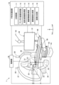
- FIG. 1 is an explanatory diagram illustrating the configuration of a surgical support system 1.
- the surgical support system 1 is a system that supports examinations and treatments.
- the surgical support system 1 includes a surgical support device 10, a blood vessel imaging device 20 having an FPD (Flat Panel Detector), a display device 30, a table 40, and an operation unit 50.
- the surgical support system 1 of the present embodiment includes a surgical support device 10 to be described later, so that the surgical support system 1 can convert the captured image (hereinafter also referred to as an "angiographic image") of a target blood vessel by an FPD into an angioimage.
- a true lumen image representing the true lumen at a corresponding position and posture can be generated, and a composite image obtained by combining the angio image and the true lumen image can be displayed.
- target blood vessel means a blood vessel that is the target of examination or treatment, but the surgical support system 1 is applicable not only to the vascular system but also to the lymph gland system, biliary tract system, urinary tract system, respiratory tract system, and digestive system. It may be used within the lumen of a living body, such as the system, secretory glands, and reproductive organs.
- FIG. 1 mutually orthogonal XYZ axes are illustrated.
- the X axis corresponds to the width direction of the blood vessel imaging device 20
- the Y axis corresponds to the height direction of the blood vessel imaging device 20
- the Z axis corresponds to the depth direction of the blood vessel imaging device 20.
- the direction in which the head 92 of the patient (FIG. 1: human body 90) is located is also simply referred to as the "Z-axis direction" and simply expressed as "Z”.
- a three-dimensional space formed by three-dimensional coordinates (XYZ coordinates) consisting of the X, Y, and Z axes is called an XYZ three-dimensional space. Note that the origin O of the XYZ three-dimensional space (XYZ coordinates) is the position of the heart 91 of the human body 90.
- the surgical support device 10 In the composite image output process described below, the surgical support device 10 generates a true lumen image representing the true lumen at a position and posture corresponding to the angio image captured by the FPD, and combines the angio image and the true lumen image. Output the composite image.
- the surgical support device 10 includes a CPU, a ROM, and a RAM, and the CPU executes a computer program stored in the ROM to control the main control unit 11, the angio image acquisition unit 12, and the ultrasound image acquisition unit 12.
- the functions of an image acquisition section 13, a true lumen information acquisition section 14, a true lumen image generation section 15, and an image composition section 16 are realized.
- the surgical support device 10 is electrically connected to each of the control section 29, display device 30, and operation section 50 of the blood vessel imaging device 20.
- the main control unit 11 transmits and receives information to and from the control unit 29, display device 30, and operation unit 50 of the blood vessel imaging device 20, and controls the entire surgical support device 10. Further, the main control unit 11 controls the entire composite image output process, which will be described later.
- the angio image acquisition unit 12 acquires a first angio image and a second angio image from the blood vessel imaging device 20 in the composite image output process.
- the "first angio image” is an angio image captured by arranging the FPD at an arbitrary imaging position.
- the imaging position of the FPD when the first image is acquired is also referred to as the "first position.”
- the “second angio image” is an angio image captured with the FPD at an arbitrary imaging position different from the first position.
- the imaging position of the FPD at which the second image is acquired is also referred to as a "second position.” Details of the first and second angio images and the first and second positions will be described later.
- the process (step) performed by the angio image acquisition unit 12 is also referred to as an angio image acquisition process (step).
- the ultrasound image acquisition unit 13 acquires, from the imaging sensor 300 (FIG. 3), an ultrasound image of the inside of the target blood vessel imaged by the imaging sensor 300 in the composite image output process. Details will be described later.
- the process (step) performed by the ultrasound image acquisition unit 13 is also referred to as an ultrasound image acquisition process (step).
- the true lumen information acquisition unit 14 uses the position information of the first position, the first angio image, the position information of the second position, the second angio image, and the ultrasound image. Three-dimensional positional information (positional information in the XYZ three-dimensional space) of the true lumen existing in the target blood vessel is acquired. Details will be described later.
- the process (step) executed by the true lumen information acquisition unit 14 is also referred to as a true lumen information acquisition process (step).
- the true lumen image generation unit 15 In the composite image output process, the true lumen image generation unit 15 generates an image corresponding to the angio image captured by the FPD located at an arbitrary imaging position (hereinafter also referred to as "first imaging position"). A true lumen image representing the true lumen at the position and posture is generated. In addition, when the FPD is moved to an arbitrary imaging position different from the first imaging position (hereinafter also referred to as "second imaging position") and imaging is performed by the FPD, the true lumen image generation unit 15 A true lumen image representing the true lumen at a position and posture corresponding to the angio image is regenerated for the angio image taken at the imaging position.
- first imaging position and the second imaging position are arbitrary positions different from the above-mentioned first position and second position, that is, arbitrary positions where the operator intends to confirm the target blood vessel and device. means location.
- first imaging position and the second imaging position may be the same as the first and second positions described above. Details will be described later.
- the process (step) executed by the true lumen image generation section 15 is also referred to as a true lumen image generation process (step).
- the image synthesis unit 16 In the composite image output process, the image synthesis unit 16 generates a composite image obtained by combining the angio image captured by the FPD placed at the first imaging position and the true lumen image generated by the true lumen image generation unit 15. generated and displayed on the display device 30. Furthermore, the image synthesis unit 16 regenerates a composite image by combining the angio image captured by the FPD placed at the second imaging position and the true lumen image regenerated by the true lumen image generation unit 15. , to be displayed on the display device 30. Details will be described later.
- the process (step) executed by the image composition unit 16 is also referred to as an image composition process (step).
- the blood vessel imaging device 20 has an FPD and acquires an image (angiography image) by acquiring X-rays that have passed through the human body and converting them into digital signals.
- the blood vessel imaging device 20 includes a first FPD 21, a first X-ray tube device 22, a first C-arm 23, a first support section 24, a second FPD 25, a second X-ray tube device 26, a second C-arm 27, and a first C-arm 23. It has two support parts 28 and a control part 29.
- the first FPD 21 includes an X-ray flat detector, converts the X-rays incident from the first X-ray tube device 22 into electrical signals, performs A/D (analog/digital) conversion, and generates an X-ray image. do.
- the first X-ray tube device 22 receives a high voltage output from an X-ray high voltage device (not shown) and irradiates an X-ray beam. As shown by the thick broken line extending in the Y-axis direction in FIG. 1, the X-ray beam irradiated from the first X-ray tube device 22 enters the first FPD 21 via the human body 90.
- the first C-arm 23 is a C-shaped arm (supporting tool) that fixes the first FPD 21 and the first X-ray tube device 22 at opposing positions.
- the first support portion 24 rotatably supports the first C-arm 23. That is, the first FPD 21 and the first X-ray tube device 22 can be moved to any imaging position around the human body 90 lying on the bed 41 while being fixed at opposing positions by the first C-arm 23.
- first FPD 21 and the first X-ray tube device 22 fixed to the first C-arm 23 will also be simply referred to as "first FPD 21.”
- the configuration of the second FPD 25 is similar to that of the first FPD 21.
- the configuration of the second X-ray tube device 26 is similar to that of the first X-ray tube device 22.
- the second C-arm 27 is a C-shaped arm (supporting tool) that fixes the second FPD 25 and the second X-ray tube device 26 in opposing positions.
- the second support part 28 rotatably supports the second C-arm 27.
- the second FPD 25 and the second X-ray tube device 26 can be moved to any imaging position around the human body 90 while being fixed at opposing positions by the second C-arm 27.
- the second FPD 25 and the second X-ray tube device 26 fixed to the second C-arm 27 will also be simply referred to as "second FPD 25.”
- the second FPD 25 is generally arranged in the normal direction of the first FPD 21.
- the first FPD 21 when the first FPD 21 is set at the imaging position in the front direction of the human body 90 (the vertical direction of the human body 90, the longitudinal direction of the human body 90), the second FPD 25 is positioned in the horizontal direction of the human body 90 (the vertical direction of the human body 90). (lateral direction) imaging position.
- the blood vessel imaging device 20 may also be simply referred to as an "FPD" or "FPD device.”
- the control unit 29 is configured to include a CPU, ROM, and RAM, and the CPU controls the entire blood vessel imaging device 20 by executing a computer program stored in the ROM.
- the control section 29 is electrically connected to each of the first FPD 21, the second FPD 25, the first support section 24, the second support section 28, the display device 30, the table 40, and the operation section 50.
- the control unit 29 causes the display device 30 to display the X-ray images generated by the first FPD 21 and the second FPD 25.
- the control section 29 drives the first support section 24 to rotate the first C-arm 23 and drives the second support section 28 to rotate the second C-arm 27 in accordance with the operation from the operation section 50 .
- the control unit 29 changes the height of the bed 41 by expanding and contracting the extendable part 42 and changes the position of the bed 41 by moving the table 40 in the Z-axis direction according to the operation from the operation part 50. .
- the display device 30 is connected to the surgery support device 10 and the control unit 29 of the blood vessel imaging device 20, and functions as an output interface for the surgery support device 10 and the blood vessel imaging device 20.
- the display device 30 includes a monitor 31 and an arm 32.
- the monitor 31 is a "display unit” configured by a well-known means such as a liquid crystal display, smart glasses, or a projector.
- the arm 32 supports and fixes the monitor 31.
- the table 40 is a stand on which the human body 90 is placed near the first FPD 21 and the second FPD 25.
- the table 40 has a bed 41, an extendable portion 42, and leg portions 43.
- the bed 41 includes a mattress on which the human body 90 lies.
- the bed 41 is supported by the table 40 so as to be movable in the Z-axis direction.
- the extensible portion 42 is configured to be able to change the height of the bed 41 by expanding and contracting in the Y-axis direction.
- the leg portions 43 support the bed 41 and the extendable portion 42. As shown by the broken line in FIG.
- the human body 90 is placed facing upward on the bed 41, with the head 92 placed on the side closer to the first FPD 21 and the second FPD 25, and the feet 93 placed on the side farther from the first FPD 21 and second FPD 25. is laid to rest. In this way, it is easy to obtain an image of the target blood vessel in the heart 91 using the first FPD 21 and the second FPD 25.
- the operation unit 50 is connected to the surgery support device 10 and the control unit 29 of the blood vessel imaging device 20, and functions as an input interface for the surgery support device 10 and the blood vessel imaging device 20.
- the operation unit 50 is an "input unit" that includes a touch panel, an operation button, an operation lever, an operation switch, a keyboard, a mouse, a voice input unit, a foot switch, and other known means. In the illustrated example, the operation unit 50 is fixed to the table 40.
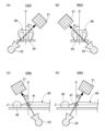
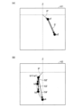
- FIG. 2 is a diagram illustrating the imaging position of the first FPD 21.
- FIG. 2(A) is a diagram for explaining LAO
- FIG. 2(B) is a diagram for explaining RAO.
- LAO Left Anterior Oblique view
- RAO Light Anterior Oblique view
- FIG. 2(C) is a diagram for explaining CRA
- FIG. 2(D) is a diagram for explaining CAU.
- the case where the first FPD 21 is positioned above the human body 90 is called CRA (CRAnial).
- CAU the case where the first FPD 21 is positioned below the human body 90 is called CAU (CAUdal). That is, the "imaging position of the first FPD 21" is specified by the combination of the horizontal position (A1) and the vertical position (A2) shown below. (A1) LAO or RAO, angle ⁇ 1 from center O of human body 90, (A2) CRA or CAU and the angle ⁇ 2 from the center O of the human body 90.
- the center O of the human body 90 is the position of the heart 91 of the human body 90 (the position of the origin O in the XYZ three-dimensional space).
- the imaging position of the first FPD 21 is (RAO28 CRA5)
- the first FPD 21 is located at a position of 28 degrees to the right of the human body 90 and at a position of 5 degrees to the upper side of the human body 90. do.
- FIG. 3 is a diagram illustrating the target blood vessel 100 and the device used.
- FIG. 3(A) is a diagram showing a longitudinal section of the target blood vessel 100
- FIG. 3(B) is a diagram showing a portion of the target blood vessel 100 surrounded by a broken line rectangle in FIG. 3(A) viewed from above. be.
- FIG. 3A shows a target blood vessel 100, a CTO 101 generated in the target blood vessel 100, a false lumen 102 formed on or under the intima of the target blood vessel 100, and a true lumen 103.
- the false lumen 102 means all dissection lumens other than the true lumen 103 formed by the medical device.
- the true lumen 103 does not necessarily extend linearly, but may meander.
- the operator in order to guide the guide wire 500 into the true lumen 103, the operator needs to direct the distal end of the guide wire 500 toward the bottom of the page.
- the FPD can only obtain a fluoroscopic image in a certain cross section, depending on the imaging position of the FPD, it is not possible to capture a part of the meandering true lumen 103 in the angio image as shown in FIG. 3(A).
- the surgical support apparatus 10 of the present embodiment can solve such a problem because it generates and displays a true lumen image representing an image of the true lumen through composite image output processing, which will be described later.
- the surgical support system 1 uses an imaging sensor 300 and a guide wire 500 shown in FIG. 3(A).
- the imaging sensor 300 is an ultrasonic sensor that acquires an ultrasonic image inside the target blood vessel 100.
- the imaging sensor 300 has an elongated outer shape and includes a transducer 301 at the tip.
- the transducer 301 is an ultrasonic probe (an ultrasonic transducer, a piezoelectric material, an ultrasonic transmitting/receiving element, an ultrasonic element, ).
- the imaging sensor 300 acquires an ultrasound image of the inside of the target blood vessel 100 around the transducer 301 while moving back and forth within the lumen of the sensor catheter 200.
- the transducer 301 rotates around the central axis of the transducer 301 (hereinafter also referred to as the transducer axis) that extends in the longitudinal direction of the image sensor 300, and is perpendicular to the transducer axis (360 degrees of the transducer axis).
- An ultrasound image of the inside of the target blood vessel 100 is acquired.
- the guide wire 500 is a medical device having an elongated outer shape.
- the guide wire 500 may be a plasma guide wire that includes an electrode at its tip and performs ablation of living tissue using a plasma flow.
- the wire catheter 400 may be configured to include the other electrode at the distal end.
- the guide wire 500 may be a penetrating guide wire that has a pointed portion at the tip and penetrates living tissue using the pointed portion, or may be a delivery guide wire that does not have a pointed portion. good.
- the guide wire 500 is housed in the lumen of the wire catheter 400, and the distal end portion of the guide wire 500 projects outward from the distal end portion 401 of the wire catheter 400.
- FIGS. 4 and 5 are flowcharts illustrating an example of composite image output processing.
- the composite image output process can be started at any timing, such as when the surgical support device 10 is powered on, a predetermined application is started, the blood vessel imaging device 20 is powered on, or the like.
- a case where an angio image is obtained using the first FPD 21 will be exemplified.
- the angio image may be acquired using the second FPD 25.
- the portion described as "first FPD 21" may be replaced with "second FPD 25" for processing.
- the imaging sensor 300 is simply referred to as a "sensor”
- the angio image is simply referred to as an "image”.
- FIG. 6 is a diagram illustrating a screen used in composite image output processing.
- FIG. 6(A) is a diagram showing the configuration of the operation screen OS
- FIG. 6(B) is a diagram showing an example of the first angio image V1.
- the true lumen information acquisition unit 14 proceeds with the processing while providing operational guidance to the operator.
- the true lumen information acquisition unit 14 causes the display device 30 to display an operation screen OS as shown in FIG. 6(A), and performs various operations using this operation screen OS. Display information.
- the operation screen OS includes an operation button display area A1 in which buttons for performing various operations are arranged, a canvas A2, and a guidance display area A3 in which various guidance messages are displayed.
- the canvas A2 is an area for displaying angio images sequentially acquired by the first FPD 21 and ultrasound images acquired by the imaging sensor 300. Note that in the composite image output process, the true lumen information acquisition unit 14 advances each step while updating the angio image displayed on the canvas A2 of the operation screen OS.
- the operation screen OS is just an example and can be changed in various ways.
- the guidance display area A3 of the operation screen OS may be omitted and guidance may be provided by voice.
- the guide display area A3 of the operation screen OS may be omitted, and a button with an item name attached (for example, a button labeled "first landmark placement" in the case of step S5) may be placed in the operation button display area A1. This may be used instead of guidance.
- step S1 the true lumen information acquisition unit 14 guides the first FPD 21 to prepare for imaging. Following the guidance, the operator prepares for imaging using the first FPD 21. Specifically, as shown in FIG. 1, the human body 90 is laid down on the bed 41, and the power of the blood vessel imaging device 20 is turned on.
- step S2 the true lumen information acquisition unit 14 guides the imaging sensor 300 to prepare for imaging. Following the guidance, the surgeon prepares for imaging using the imaging sensor 300. Specifically, as shown in FIG. 3A, an imaging sensor 300 and a guide wire 500 are inserted into a blood vessel of a human body 90, and the transducer 301 of the imaging sensor 300 and the distal end of the guide wire 500 It is delivered so as to be located near the CTO 101 of the blood vessel 100.
- step S3 the true lumen information acquisition unit 14 guides the first FPD 21 to move to the first position and capture an X-ray image. Following the guidance, the operator moves the first FPD 21 to the first position and captures an X-ray image of the target blood vessel 100, thereby obtaining a first angio image V1.
- the first position can be any position (RAO XX CRA XX: X is any natural number).
- the true lumen information acquisition unit 14 may automatically move the first FPD 21 to the first position and perform imaging.
- the angio image acquisition unit 12 acquires the captured first angio image V1 from the blood vessel imaging device 20. As shown in FIG.
- the first angio image V1 includes an image of the imaging sensor 300, an image of the guide wire 500, and an image of the target blood vessel 100 through which the imaging sensor 300 and the guide wire 500 are inserted ( (not shown).
- the imaging sensor 300 is illustrated with a broken line
- the guide wire 500 is illustrated with a solid line.
- the first angio image V1 includes an image of the target blood vessel 100.
- the first angio image V1 only needs to include the image of the imaging sensor 300 and the image of the guide wire 500, and does not need to include the image of the target blood vessel 100.
- the "image of the target blood vessel 100" means an image of the outline of the target blood vessel 100.
- step S4 the true lumen information acquisition unit 14 displays the first angio image V1 on the canvas A2, and positions the image of the transducer 301 (see FIG. 3) among the images of the imaging sensor 300 at the center of the canvas A2.
- the position of the first angio image V1 is adjusted so that
- FIG. 7 is a diagram illustrating steps S5 and S7 of the composite image output process.
- FIG. 7(A) is a diagram showing the state of the canvas A2 in step S5
- FIG. 7(B) is a diagram showing the state of the canvas A2 in step S7.
- a square or rectangular canvas A2 has an origin Oc at the top left corner of the page, and XcYc coordinates, which are two-dimensional coordinates consisting of an Xc axis extending to the right of the page and a Yc axis extending downwards of the page. have.
- the two-dimensional space formed by the XcYc coordinates is called the XcYc two-dimensional space.
- the negative direction of the Yc axis is the direction in which the head 92 of the human body 90 (see FIG. 1) is located.
- the true lumen information acquisition unit 14 guides the user to place the first mark a1 on the image of the transducer 301 of the imaging sensor 300 in the first angio image V1 displayed on the canvas A2.
- the surgeon places the first mark a1 on the first angio image V1 on the canvas A2, as shown in FIG. 7(A).
- the placement of the first mark a1 can be achieved, for example, by clicking or tapping the intended position on the image of the canvas A2.
- the actual position (position in the XYZ coordinates) of the transducer 301 inside the target blood vessel 100 is assumed to be P1. .
- step S6 the true lumen information acquisition unit 14 guides the user to acquire the ultrasound image IV1 using the imaging sensor 300 while maintaining the position of the imaging sensor 300.
- the operator acquires an ultrasound image IV1 from the imaging sensor 300 without moving the imaging sensor 300 from the position shown in FIG. 7(A).
- the ultrasound image acquisition unit 13 acquires the captured ultrasound image IV1 from the imaging sensor 300, and stores the ultrasound image IV1 in the storage unit inside the surgery support device 10. That is, the ultrasound image acquisition unit 13 acquires an ultrasound image IV1 when the transducer 301 is located at P1 within the target blood vessel 100.
- the first angio image V1 acquired in step S3 includes the target blood vessel 100, the image of the imaging sensor 300 placed at the first landmark position (first mark a1) in the target blood vessel 100, and the target blood vessel 100 (an arbitrary position different from the first mark a1).
- the ultrasound image IV1 acquired in step S6 also includes the target blood vessel 100 and the guide wire 500 placed at a second landmark position (an arbitrary position different from the first landmark a1) within the target blood vessel 100. , will be included.
- step S7 the true lumen information acquisition unit 14 advances the imaging sensor 300 within a range that can be regarded as a straight line, and then guides the imaging sensor 301 to place the second mark a2 on the transducer 301.
- "straight line” means that the trajectory of the transducer 301 when moving inside the sensor catheter 200 is a straight line.
- the operator advances the imaging sensor 300 by a range (distance) that can be regarded as a straight line, and then places the second landmark a2 on the first angio image V1 on the canvas A2. Deploy.
- the actual position (position in the XYZ coordinates) of the transducer 301 inside the target blood vessel 100 is Pe. .
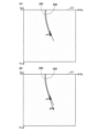
- FIG. 8 is a diagram illustrating step S8 of the composite image output process.
- FIGS. 8A and 8B are diagrams illustrating calculation of BNV, which will be described later.
- FIG. 8(C) is a diagram showing the relationship between a first angio image V1 at a first position and a second angio image V2 at a second position, which will be described later.
- FIG. 8(D) is a diagram showing the first angio image V1 at the first position.
- FIG. 8(E) is a diagram showing the second angio image V2 at the second position.
- step S8 the true lumen information acquisition unit 14 calculates the BNV using the first mark a1, the second mark a2, and the first position in the first angio image V1 on the canvas A2. Specifically, as shown in FIG. 8A, the true lumen information acquisition unit 14 generates a vector (a vector representing the trajectory of the transducer 301 that can be regarded as a straight line) having the first landmark a1 as the starting point and the second landmark a2 as the ending point. ) is the first shaft axis vector Ie' of the imaging sensor 300, and the vector representing the first view, which is the imaging direction of the first FPD 21 placed at the first position with respect to the heart 91 (see FIG. 1), is the first view vector Vw1.
- a vector a vector representing the trajectory of the transducer 301 that can be regarded as a straight line
- the BNV for the plane W including the first shaft axis vector Ie' and the first view vector Vw1 is calculated. Furthermore, since the plane W is a plane that includes the first shaft axis vector Ie', the distance from P1 (corresponding to the first landmark a1) to Pe (corresponding to the second landmark a2) of the transducer 301 in the XYZ three-dimensional space is It can be said that it is the plane on which the orbit lies.
- BNV means the imaging direction perpendicular to the plane W, as shown in FIG. 8(A). That is, BNV means an imaging direction in which a second angio image V2 perpendicular to the first angio image V1 can be obtained.
- the vector representing the second view be a second view vector Vw2.
- the true lumen information acquisition unit 14 obtains a numerical value RL val representing LAO or RAO, which is positional information of the first FPD 21 at the first position (also simply referred to as "positional information of the first position"), and a numerical value CC representing CRA or CAU.
- " ⁇ " and “ ⁇ ” are variables for displaying the first view vector Vw1 in polar coordinates.
- CW means “clockwise”
- CCW means "counterclockwise”.
- the true lumen information acquisition unit 14 calculates the orthogonal coordinates of the second view vector Vw2 by substituting the calculated ⁇ , ⁇ , and ⁇ into equation (2).
- the true lumen information acquisition unit 14 converts the orthogonal coordinates (x, y, z) of the second view vector Vw2 into polar coordinates (r, ⁇ , ⁇ ) using equation (3).
- the true lumen information acquisition unit 14 obtains a numerical value RL val representing LAO or RAO at the second position and a numerical value CC val representing CRA or CAU from the polar coordinates (r, ⁇ , ⁇ ) of the second view vector Vw2. calculate.
- the imaging sensor 300 is in the posture shown in FIG. 8(C) within the target blood vessel 100.
- the imaging sensor 300 was advanced within a range that can be regarded as a straight line, so the first angio image V1 is an image obtained from the first view in the direction in which the imaging sensor 300 appears to be a straight line, that is, the first position. I can say that there is. Therefore, the imaging sensor 300 is captured in a straight line in the first angio image V1, as shown in the hatched images in FIGS. 8(C) and 8(D).
- the second angio image V2 obtained from the second view at the second position is perpendicular to the first angio image V1.
- This can be said to be an image acquired from a direction in which the imaging sensor 300 (orbit of the transducer 301) appears curved. Therefore, the imaging sensor 300 is captured in a curved shape in the second angio image V2, as shown in the dot-hatched images in FIGS. 8(C) and 8(E).
- step S9 the true lumen information acquisition unit 14 guides the transducer 301 of the imaging sensor 300 to return to the position of the first landmark a1. Following the guidance, the operator pulls the transducer 301 back to the position of the first landmark a1. That is, the operator pulls the transducer 301 inside the target blood vessel 100 back from the position Pe in the XYZ coordinates to P1.
- step S10 the true lumen information acquisition unit 14 guides the first FPD 21 to move to the second position corresponding to the BNV calculated in step S8 and to capture an X-ray image.
- the operator moves the first FPD 21 to the second position and captures an X-ray image of the target blood vessel 100, thereby obtaining a second angio image V2.
- the true lumen information acquisition unit 14 may automatically move the first FPD 21 to the second position and perform imaging.
- the angio image acquisition unit 12 acquires the captured second angio image V2 from the blood vessel imaging device 20. As will be described later in FIG.
- the second angio image V2 includes an image of the imaging sensor 300, an image of the guide wire 500, an image of the imaging sensor 300 and the guide wire, which are captured from a different direction from the first angio image V1.
- 500 is inserted into the target blood vessel 100 (not shown).
- the second angio image V2 includes an image of the target blood vessel 100.
- the second angio image V2 only needs to include the image of the imaging sensor 300, and does not need to include the image of the target blood vessel 100 or the image of the guide wire 500.
- step S11 the true lumen information acquisition unit 14 displays the second angio image V2 on the canvas A2, and displays the second angio image so that the image of the transducer 301 of the imaging sensor 300 is located at the center of the canvas A2. Adjust the position of V2.
- FIG. 9 is a diagram illustrating steps S12 to S17 of the composite image output processing.
- FIG. 9 shows an example of the second angio image V2 on the canvas A2.
- the true lumen information acquisition unit 14 guides the user to place the first mark b1 on the image of the transducer 301 of the imaging sensor 300 in the second angio image V2 displayed on the canvas A2.
- the surgeon places the first mark b1 on the second angio image V2 on the canvas A2.
- the placement of the first mark b1 can be achieved, for example, by clicking or tapping the intended position on the image of the canvas A2.
- step S13 the true lumen information acquisition unit 14 substitutes 2 for the variable n used in the composite image output process.
- n is a natural number.
- step S14 the true lumen information acquisition unit 14 advances the imaging sensor 300 by an arbitrary distance and guides the imaging sensor 300 to place the second mark b2 on the transducer 301. Following the guidance, the operator advances the imaging sensor 300 and then places the second mark b2 on the second angio image V2 on the canvas A2. Note that on the second angio image V2, when the image of the transducer 301 is located at the second mark b2 of the XcYc coordinates on the canvas A2, the actual position (position in the XYZ coordinates) of the transducer 301 within the target blood vessel 100 is assumed to be P2. .
- the true lumen information acquisition unit 14 guides the user to acquire the ultrasound image IV2 using the imaging sensor 300 while maintaining the position of the imaging sensor 300. Following the guidance, the operator acquires an ultrasound image IV2 from the imaging sensor 300 without moving the imaging sensor 300.
- the ultrasound image acquisition unit 13 acquires the captured ultrasound image IV2 from the imaging sensor 300, and stores the ultrasound image IV2 in the storage unit inside the surgery support device 10. That is, the ultrasound image acquisition unit 13 acquires an ultrasound image IV2 when the transducer 301 is located at P2 within the target blood vessel 100.
- the true lumen information acquisition unit 14 adds 1 to the variable n.
- step S17 the true lumen information acquisition unit 14 arranges the landmarks on the second angio image V2 (step S14) and acquires an ultrasound image at the location of the landmarks (step S15) with the desired number of landmarks. Determine whether or not the task has been completed.
- step S17: YES the true lumen information acquisition unit 14 shifts the process to step S18. If the variable n has not reached the target number of landmarks (step S17: NO), the true lumen information acquisition unit 14 shifts the process to step S14 and repeats the above-described process. As a result, as shown in FIG.
- each An ultrasound image IVn corresponding to the location of the n-th landmark bn is acquired (step S15).
- the range in which the imaging sensor 300 is pushed on the second angio image V2 is the range in which the imaging sensor 300 can be regarded as a straight line on the first angio image V1, that is, from the first landmark a1 to the second landmark a2 (target (In the blood vessel 100, from position P1 to Pe).
- FIG. 10 is a diagram illustrating step S18 of the composite image output process.
- FIG. 10(A) is a diagram showing each point on the first angio image V1 displayed on the canvas A2
- FIG. 10(B) is a diagram showing each point on the second angio image V2 displayed on the canvas A2.
- FIGS. 10A and 10B which are diagrams showing the above, the upper side of the page is oriented toward the Z axis of the XYZ coordinates (FIG. 1: the direction in which the head 92 of the human body 90 is located). That is, the negative direction of the Yc axis of the canvas A2 is the direction in which the head 92 of the human body 90 in FIG. 1 is located.
- the Yc' axis is a straight line parallel to the Yc axis.
- step S18 the true lumen information acquisition unit 14 obtains each coordinate in the XcYc coordinates of the first landmark a1 and the second landmark a2 in the first angio image V1 displayed on the canvas A2, and the first landmark b1 in the second angio image V2.
- Each coordinate in the XcYc coordinates of the n-th landmark bn is used to calculate the following (B1) and (B2).
- the transducer axis vectors T1 to Tn are the transducer axes (of the imaging sensor 300) when the transducer 301 is located at positions P1 to Pn in the target blood vessel 100. This is a vector of the central axis of the transducer 301 extending in the longitudinal direction.
- the transducer axis vector when the transducer 301 is located at the positions P1 to Pn can be said to be the tangential vector at the positions P1 to Pn on the trajectory of the transducer 301.
- the first angio image V1 and the second angio image V2 displayed on the canvas A2 are images of the imaging sensor 300 captured from different angles.
- the first shaft axis vector Ie' is a vector extending from the first mark a1 to the second mark a2 on the first angio image V1.
- the second shaft axis vector P2' is a vector extending from the first mark b1 to the second mark b2 on the second angio image V2
- the second shaft axis vector Pn' is a vector extending from the first mark b1 to the nth mark is a vector extending to bn.
- the tangent vector T' on the trajectory of the transducer 301 that has passed the first landmark a1 and the second landmark a2 is on the first shaft axis vector Ie'.
- the orientation of "(B2) transducer axis vectors T1 to Tn of the transducer 301 of the imaging sensor 300" is determined by the inclination ⁇ of the shaft axis vector Ie' with respect to the Yc axis in the first angio image V1 and the inclination ⁇ of the shaft axis vector Ie' in the first angio image V1 with respect to the Yc axis.
- the tangent vector T1' in the second angio image V2 is the tangent vector at the first landmark b1 on the trajectory of the transducer 301 extending from the first landmark b1 to the n-th mark bn.
- the tangential vector Tn' is the tangential vector at the n-th landmark bn on the trajectory of the transducer 301.
- first and second angio images V1 and V2 taken at different first and second positions, respectively, a first view vector Vw1 representing the imaging direction of the first FPD 21 at the first position and a transducer reflected on the first angio image V1 are obtained.
- Details of the method for determining the direction of the vector of an object located on a straight line intersecting the plane defined by the second shaft axis vectors P2' to Pn' are disclosed in International Application No.
- PCT/JP2021/034980 In the international application PCT/JP2021/034980, a straight line where the H2 plane and the S plane intersect is defined using the blood vessel existence plane H2 seen from the first position and the blood vessel existence plane S seen from the second position. , the "blood vessel axis vector", which is the straight line, is calculated.
- a first view vector Vw1 representing the imaging direction of the first FPD 21 at the first position
- a first shaft axis vector Ie' representing the trajectory of the transducer 301 reflected on the first angio image V1.
- the plane defined by the vector corresponds to the H2 plane, and is determined by the second view vector Vw2 representing the imaging direction of the first FPD 21 at the second position and the second shaft axis vectors P2' to Pn' reflected on the second angio image V2.
- the defined plane corresponds to the S plane, and the position vectors P2 to Pn calculated in the above (B1) may be calculated as corresponding to the blood vessel axis vector. Further, the transducer axis vectors T1 to Tn calculated in the above (B2) can be similarly calculated as being equivalent to the blood vessel axis vector.
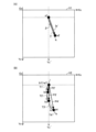
- FIG. 11 is a diagram illustrating calculation of the lengths of the position vectors P2 to Pn of the transducer 301. Specifically, FIG. 11 explains, as an example, calculation of the length of the position vector P2 of the transducer 301 when the transducer 301 moves from the starting point (reference point) P1 to the ending point P2 in the target blood vessel 100. It is a diagram. The length of the position vector Pn can be similarly calculated.
- vector Vw2 is a second view vector Vw2 (see FIG. 8(A)) representing the imaging direction when the first FPD 21 is in the second position.
- b1 is the first mark b1 on the second angio image V2, and is the position of the transducer 301 on the second angio image V2 when the transducer 301 is located at the starting point P1.
- b2 is the second mark b2 on the second angio image V2, and is the position of the transducer 301 on the second angio image V2 when the transducer 301 is located at the end point P2.
- Vector P2' is the second shaft axis vector P2' of the transducer 301 on the second angio image V2, and is an orthogonal projection vector of the position vector P2 of the transducer 301 onto the second angio image V2.
- ⁇ is an angle formed by the second view vector Vw2 and the position vector P2.
- step S18 the true lumen information acquisition unit 14 calculates the length of the above-mentioned "(B1) position vectors P2 to Pn of the transducer 301" using the following equation (4).
- ⁇ can be calculated using the first equation of equation (4) based on the inner product formula of vectors.
- the length of the second shaft axis vector P2' can be calculated from the coordinates b1 and b2 in the XcYc coordinates of the canvas A2, the length of the position vector P2 can be derived from the second equation of equation (4).
- Vw2 ⁇ P2 represents the inner product of the second view vector Vw2 and the position vector P2
- P2 and P2" ''' represents the length of the position vector P2 and the second shaft axis vector P2', respectively.
- FIG. 12 is a diagram illustrating steps S19 to S21 of the composite image output process.
- FIG. 12(A) is a diagram showing an example of an angio image V ⁇ when the first FPD 21 is placed at position ⁇ .
- FIG. 12(B) is a diagram showing the relationship among the first FPD 21, the imaging sensor 300, and the guide wire 500 when the first FPD 21 is placed at the position ⁇ .
- the angio image V ⁇ is an angio image captured by the first FPD 21 located at a position ⁇ where the transducer 301 and the guide wire 500 appear to overlap when the transducer 301 is located at P1 in the target blood vessel 100. .
- step S20 the true lumen information acquisition unit 14 obtains an ultrasound image IV1 (an ultrasound image when the transducer 301 is located at the first landmark b1 on the second angio image V2, that is, an ultrasound image when the transducer 301 is located inside the target blood vessel 100).
- An ultrasound image obtained when the camera is positioned at P1) is displayed on canvas A2.
- step S21 the true lumen information acquisition unit 14 performs orientation calibration processing (directions from the transducer 301 to the guide wire 500 in the XYZ three-dimensional space and the direction from the transducer 301 to the guide wire 500 in the ultrasound image IV1 displayed in the XcYc two-dimensional space of the canvas A2). (a process of associating the direction toward the wire 500).
- the true lumen information acquisition unit 14 acquires the position ⁇ of the first FPD 21 in step S19.
- a vector representing the imaging direction of the first FPD 21 placed at position ⁇ with respect to the heart 91 is defined as a view vector Vw ⁇ .
- the true lumen information acquisition unit 14 calculates a view vector Vw ⁇ from the acquired position ⁇ of the first FPD 21. As shown in equation (5), the true lumen information acquisition unit 14 uses the cross product of the transducer axis vector T1 of the imaging sensor 300 at the position P1 in the target blood vessel 100 calculated in (B2) above and the view vector Vw ⁇ . Calculate the rotation axis R (r1, r2, r3).
- the true lumen information acquisition unit 14 converts the transducer axis vector T1 of the transducer 301 calculated in (B2) above by 90 degrees around the rotation axis R obtained from Equation (5).
- Equation (7) is a matrix representation of Rodriguez's rotation formula shown in Equation (6).
- FIG. 13 is a diagram showing an example of the ultrasound image IV1 displayed on the canvas A2 in step S20.
- the ultrasound image IV1 is a target blood vessel in a direction perpendicular to the transducer axis T1 (360° circumferential direction of the transducer axis T1) when the transducer 301 is at the first landmark b1 of the second angio image V2.
- This is an ultrasound image of the inside of 100.
- the ultrasound image IV1 includes an image of the guide wire 500 (a portion that appears relatively white compared to the surrounding area) and an image of the true lumen 103 (a portion that appears relatively black compared to the surrounding area).
- an arrow CV is displayed from the center of the ultrasound image IV1 (that is, the center of the transducer 301) toward the center of the image of the guide wire 500.
- the extending direction of the arrow CV in the XcYc two-dimensional space of the canvas A2 corresponds to the direction of the calculated vector CV1 in the XYZ three-dimensional space.
- step S21 in this way, the direction from the transducer 301 to the guide wire 500 in the XYZ three-dimensional space and the direction from the transducer 301 to the guide wire 500 in the ultrasound image IV1 displayed in the XcYc two-dimensional space of the canvas A2 are determined. An association is made.
- FIG. 14 is a diagram illustrating step S22 of the composite image output process.
- the true lumen information acquisition unit 14 performs size calibration processing (processing that associates the number of pixels of the ultrasound image IV1 displayed on the canvas A2 with the actual dimensions of the ultrasound image IV1).
- a scale SC representing the actual dimensions of the target blood vessel 100 is attached to the ultrasound image IV1.
- the interval between adjacent scale marks is 1 mm.
- the true lumen information acquisition unit 14 draws a line segment from the center of the image of the target blood vessel 100 to a scale located outside the outline of the image of the target blood vessel 100, and draws a line segment on the ultrasound image IV1 of the canvas A2.
- the number of pixels (Fig. 14: x pixel) is measured.
- the true lumen information acquisition unit 14 calculates the number of pixels on the canvas A2 per 1 mm of actual size by calculating the number of measured pixels/the length of the line segment.
- FIG. 15 is a diagram illustrating step S23 of the composite image output process.
- FIG. 15 shows an example of the ultrasound image IV1 displayed on the canvas A2 in step S23.
- the true lumen information acquisition unit 14 calculates a true lumen vector S1 (a vector that is perpendicular to the transducer axis T1 and extends from the transducer 301 to the true lumen 103) in the XYZ three-dimensional space. Specifically, the true lumen information acquisition unit 14 moves an arrow from the center of the ultrasound image IV1 (that is, the center of the transducer 301 of the imaging sensor 300) toward the center of the image of the guide wire 500 in the ultrasound image IV1. Instruct them to submit a CV. As shown in FIG.
- the image of the portion where the transducer 301 is located is located near the center of the ultrasound image IV1, and appears relatively black compared to the surrounding area. Further, since the image of the guide wire 103 appears relatively white compared to the surrounding area, the operator who views the ultrasound image IV1 can grasp the positions of the transducer 301 and the guide wire 500. Following the guidance, the operator draws an arrow CV pointing from the center of the ultrasound image IV1 to the center of the image of the guide wire 500.
- the arrow CV can be drawn by, for example, clicking or tapping the center of the transducer 301 and the center of the image of the guide wire 500 on the ultrasound image IV1 of the canvas A2.
- the vector indicated by arrow CV that is, the vector extending from the center of transducer 301 to the center of guide wire 500 in XcYc coordinates
- the true lumen information acquisition unit 14 also moves an arrow S from the center of the ultrasound image IV1 (that is, the center of the image of the transducer 301 of the imaging sensor 300) toward the center of the image of the true lumen 103 of the ultrasound image IV1. I will guide you to pull it.
- the true lumen 103 appears relatively black on the ultrasound image IV1 compared to the surrounding area, the operator who views the ultrasound image IV1 can grasp the position of the true lumen 103.
- the operator draws an arrow S pointing from the center of the ultrasound image IV1 to the center of the image of the true lumen 103.
- the arrow S can be drawn by, for example, clicking or tapping the center of the transducer 301 and the center of the image of the true lumen 103 on the image of the canvas A2.
- the vector indicated by arrow S that is, the vector extending from the center of transducer 301 to the center of true lumen 103 in XcYc coordinates, be vector s.
- the angle formed by the vector cv and the vector s is assumed to be ⁇ .
- the true lumen information acquisition unit 14 calculates the angle ⁇ formed by the vector cv and the vector s from the vector cv and the vector s in the XcYc coordinates of the canvas A2 using the formula of the inner product of vectors. Then, as shown in equation (8), the true lumen information acquisition unit 14 calculates in step S21 using the transducer axis vector T1 (r1, r2, r3) of the imaging sensor 300 calculated in (B2) above as the rotation axis. By rotating the vector CV1 by ⁇ degrees, the direction of the true lumen vector S1 on the XYZ three-dimensional space is calculated. Note that Equation (9) is a matrix representation of Rodriguez's rotation formula shown in Equation (8).
- the true lumen information acquisition unit 14 also acquires the number a of pixels of the arrow S drawn at the XcYc coordinates of the canvas A2, and the number c of pixels corresponding to the width of the image of the true lumen 103 of the ultrasound image IV1. Note that the number of pixels c of the image of the true lumen 103 may be automatically obtained by image analysis of the ultrasound image IV1, or the width may be specified by the operator. After that, the true lumen information acquisition unit 14 substitutes the acquired number of pixels a and the result b of step S22 (the number of pixels b on the canvas A2 per 1 mm of actual size) into equation (10). , calculate the actual length S length (mm) of the true lumen vector S1.
- the true lumen information acquisition unit 14 substitutes the acquired pixel number c and the result b of step S22 into equation (11), thereby determining the true lumen of the portion corresponding to the true lumen vector S1. Calculate the actual width S width (mm).
- FIG. 16 is a diagram illustrating steps S24 to S28 of the composite image output process.
- the true lumen information acquisition unit 14 substitutes 2 for the variable n used in the composite image output process.
- step S26 the true lumen information acquisition unit 14 calculates the true lumen vector Sn. Specifically, the true lumen information acquisition unit 14 guides the user to draw an arrow S from the center of the ultrasound image IV2 displayed on the canvas A2 toward the image of the true lumen 103 in the ultrasound image IV2. Thereafter, the true lumen information acquisition unit 14 calculates the angle ⁇ d (FIG. 16) formed by the transducer axis vector T1 of the imaging sensor 300 calculated in the above (B2) and the transducer axis vector T2 of the imaging sensor 300. The true lumen information acquisition unit 14 calculates a vector CV2 by rotating the vector CV1 calculated in step S21 by the same amount as the calculated angle ⁇ d.
- the angle ⁇ d FIG. 16
- the rotation axis for rotating the vector CV1 by ⁇ d is calculated by the cross product of the transducer axis vectors T1 and T2.
- the process is the same as step S23.
- the true lumen information acquisition unit 14 acquires the angle ⁇ formed by the arrow CV and the arrow S drawn in the ultrasound image IV2.
- the true lumen information acquisition unit 14 calculates the direction of the true lumen vector S2 by rotating the vector CV2 by ⁇ degrees using the transducer axis vector T2 of the imaging sensor 300 as the rotation axis, as shown in equation (8).
- the true lumen information acquisition unit 14 also acquires the number a of pixels of the arrow S drawn in the ultrasound image IV2, and the number c of pixels corresponding to the width of the image of the true lumen 103 in the ultrasound image IV2.
- the true lumen information acquisition unit 14 calculates the actual length S length (mm) of the true lumen vector S2 by substituting the number of pixels a and the number of pixels c into equations (10) and (11), respectively. , the actual width S width (mm) of the true lumen in the portion corresponding to the true lumen vector S2.
- step S28 the true lumen information acquisition unit 14 determines whether the calculation of the true lumen vector Sn (step S26) has been completed for the desired number of landmarks defined in steps S14 to S17.
- step S28: YES the true lumen information acquisition unit 14 shifts the process to step S29. If the variable n has not reached the target number of landmarks (step S28: NO), the true lumen information acquisition unit 14 shifts the process to step S25 and repeats the above-described process.
- the true lumen information acquisition unit 14 stores the three-dimensional position information (position information in the XYZ three-dimensional space) of the true lumen 103 acquired in steps S23 to S28 in the storage unit inside the surgical support device 10. That is, in the example of this embodiment, the three-dimensional position information of the true lumen 103 includes the directions of the true lumen vectors S1 to Sn in the XYZ three-dimensional space, the lengths S length (mm) of the true lumen vectors S1 to Sn, and , the actual size S width (mm) of the true lumen of the portion corresponding to the true lumen vectors S1 to Sn.
- the actual size S width of the true lumen corresponds to "information regarding the width of the true lumen.”
- the three-dimensional position information of the true lumen may include the number of pixels c of the image of the true lumen in the portion corresponding to the true lumen vectors S1 to Sn, instead of the actual size S width of the true lumen.
- the number of pixels c corresponds to "information regarding the width of the true lumen.”
- the true lumen information acquisition unit 14 can detect the true lumen 103 obtained from the ultrasound image IV1 even if the first angio image V1 and the second angio image V2 do not include an image of the true lumen 103. Based on the information, three-dimensional position information of the true lumen 103 can be obtained.
- FIGS. 17 and 18 are diagrams explaining step S30 of the composite image output process.
- FIG. 17(A) shows that the true lumen vector Sn in the XYZ three-dimensional space and the true lumen vector Sn are aligned in the imaging direction of the first FPD 21 located at the imaging position A (the direction of the white arrow from the top to the bottom of the page).
- ) is a diagram showing a true lumen image VY formed by being projected (orthogonally projected) onto a projection plane VY', and an orthogonal projection vector Spn of a true lumen vector Sn on the true lumen image VY.
- FIGS. 17B and 17C are diagrams illustrating calculation of the orthogonal projection vector Spn of the true lumen vector Sn.
- FIG. 18(A) is a diagram showing an example of an angio image VX at an arbitrary FPD position.
- FIG. 18(B) is a diagram showing an example of a true lumen image VY corresponding to the angio image V
- the image synthesis unit 16 displays a true lumen image superimposed on a captured image (angiography image) at an arbitrary FPD position.
- the true lumen image generation section 15 and the image composition section 16 perform the processes described in the following (C1) to (C4).
- C1 The true lumen image generation unit 15 acquires an angio image VX of the target blood vessel 100 captured by the first FPD 21 (see FIG. 17(A)) placed at an arbitrary imaging position A.
- the imaging position A corresponds to a "first imaging position.”
- the true lumen image generation unit 15 acquires position information of the imaging position A from the first FPD 21.
- the true lumen image generation unit 15 acquires three-dimensional position information of the true lumen from a storage unit included in the surgical support device 10 (see FIG. 1).
- the true lumen image generation unit 15 uses the positional information of the imaging position A and the three-dimensional positional information of the true lumen to generate a true lumen image at a position and posture corresponding to the angioimage VX of the imaging position A.
- a cavity image VY is generated.
- the method for generating the true lumen image VY will be described later in (D1) to (D7).
- the image composition unit 16 generates a composite image V by combining the angio image VX and the true lumen image VY, and displays the composite image V on the canvas A2.
- the angio image VX includes an image of the imaging sensor 300 viewed from an arbitrary imaging position A, an image of the guide wire 500, and an image of the target blood vessel 100 (not shown).
- the true lumen image VY includes an image of the true lumen 103 at a position and orientation corresponding to the angio image VX (in other words, when viewed from the imaging position A where the angio image VX was acquired).
- the position of the true lumen is synonymous with the coordinates of the image of the true lumen 103 on the true lumen image VY.
- the posture of the true lumen is synonymous with the orientation of the image of the true lumen 103 on the true lumen image VY.
- the true lumen image generation unit 15 generates a true lumen image VY according to the following steps (D1) to (D7).
- D1 As shown in FIG. 17(A), a vector extending perpendicularly from the imaging position A to the projection plane VY' (hereinafter, the true lumen image VY is referred to as the projection plane VY') is defined as the view vector VnA. (That is, the view vector VnA is a vector representing the imaging direction of the first FPD 21 placed at the imaging position A with respect to the heart 91 (see FIG. 1)).
- the true lumen image generation unit 15 defines the view vector VnA in the XYZ three-dimensional space by the first equation of equation (12), and from the first equation of equation (12), the plane is perpendicular to the view vector VnA.
- the second equation (vector a1 and vector a2) of equation (12) representing the true lumen image VY is calculated.
- the true lumen image generation unit 15 sets the true lumen image VY defined by the vector a1 and the vector a2 calculated in step (D1) as a matrix A, and calculates the three-dimensional image of the true lumen 103 according to equation (13).
- a projection matrix P is calculated for calculating an orthogonal projection vector Spn of the true lumen vector Sn included in the position information onto the true lumen image VY. Note that in equation (13), matrix A T means a transposed matrix of matrix A.
- the true lumen image generation unit 15 generates a true lumen image VY using equation (14) regarding the true lumen vector Sn and the Z axis in the XYZ three-dimensional space (FIG. 1: the direction in which the head 92 of the human body 90 is located).
- Orthogonal projection vectors Spn and Zp are calculated. Note that in equation (14), Ze means a unit vector representing the Z axis in the XYZ three-dimensional space. Further, the orthogonal projection vectors Spn and Zp calculated by equation (14) are vectors on the true lumen image VY expressed in XYZ coordinates.
- the true lumen image generation unit 15 converts the orthogonal projection vector Spn calculated in step (D3) into two-dimensional coordinates on the true lumen image VY, and calculates the orientation of the orthogonal projection vector Spn on the true lumen image VY. do. Specifically, as shown in FIG. 17(B), the true lumen image generation unit 15 first calculates the orthogonal projection vector Spn of the true lumen vector Sn onto the true lumen image VY and the truth of the Ze vector representing the Z axis. The angle ⁇ p formed by the orthogonal projection vector Zp onto the cavity image VY is calculated.
- ⁇ p is calculated by, for example, the inner product formula of vectors.
- the orthogonal projection vector Spn and the orthogonal projection vector Zp are displayed on the canvas A2 having XcYc coordinates (that is, it is assumed that the true lumen image VY is displayed on the canvas A2 as shown in FIG. 17(B)).
- the vector Zp can be said to have the same direction as the Z axis in the XYZ three-dimensional space, and thus be parallel to the Yc axis.
- the direction of the vector Zp is the direction where the head 92 of the human body 90 is, that is, the direction from the bottom to the top of the paper in FIG. 17(B), so the Yc-axis is It's the exact opposite direction.
- the true lumen image generation unit 15 sets the unit vector of the orthogonal projection vector Spn in the XcYc coordinates to the orthogonal projection unit vector Spn' (x', y'), and calculates it using equation (15) or equation (16). It can be said that the orthogonal projection unit vector Spn' (x', y') represents the direction of the orthogonal projection vector Spn on the true lumen image VY.
- Equation (15) is for the case where the orthogonal projection unit vector Spn' is in the clockwise direction (CW) when viewed from the orthogonal projection vector Zp
- Equation (16) is for the case where the orthogonal projection unit vector Spn' is in the clockwise direction (CW) when viewed from the orthogonal projection vector Zp. This is the case in the counterclockwise direction (CCW) when viewed from.
- the true lumen image generation unit 15 calculates the angle formed by the true lumen vector Sn and the view vector VnA in order to calculate the length of the orthogonal projection vector Spn of the true lumen vector Sn. Specifically, as shown in FIG. 17(c), the angle formed by the true lumen vector Sn and the view vector VnA is ⁇ , and the true lumen vector Sn and the view vector VnA are calculated based on the formula of the cross product of vectors. Then, sin ⁇ is calculated by equation (17). Note that in equation (17), VnA ⁇ Sn means the outer product of the view vector VnA and the true lumen vector Sn.
- the true lumen image generation unit 15 calculates the true lumen vector using the sin ⁇ calculated in step (D5).
- the length Spn length of the orthogonal projection vector Spn of the cavity vector Sn is calculated by equation (18) (see FIG. 17(c)).
- the true lumen image generation unit 15 calculates the orthogonal projection vector Spn of the true lumen vector Sn at the XcYc coordinates of the canvas A2 using equation (15), equation (16), equation (18), and equation (19). Calculate (x, y). It can be said that the orthogonal projection vector Spn (x, y) represents the direction and length of the orthogonal projection vector Spn on the true lumen image VY.
- the true lumen image generation unit 15 generates the true lumen image VY using the orthogonal projection vector Spn(x,y) obtained in step (D6).
- FIG. 19 is a diagram showing an example of a composite image.
- FIG. 19(A) is a diagram showing an example of a composite image V at an arbitrary imaging position A.
- FIG. 19B is a diagram illustrating an example of a composite image Vb at an imaging position B that is different from the imaging position A.
- a composite image V shown in FIG. 19(A) is displayed on the canvas A2.
- the composite image V is an image in which the true lumen image VY is superimposed on the angio image VX shown in FIG.
- the image of the true lumen 103 is at a position and orientation corresponding to the angioimage VX at the imaging position A, and further has a width corresponding to the three-dimensional position information of the true lumen. have.
- the true lumen image generation unit 15 further uses the actual size S width (mm) of the true lumen included in the three-dimensional position information of the true lumen, The width of the image of the true lumen 103 may be changed.
- the true lumen image generation unit 15 and the image synthesis unit 16 use the position information of the changed imaging position B (that is, the position information of the second imaging position) to perform the steps (C1) to Repeat (C4).
- the angio image VX includes images of the imaging sensor 300, guide wire 500, and target blood vessel 100 viewed from different angles, and an image of the true lumen 103 corresponding to the angle.
- a composite image Vb obtained by combining the true lumen image VY and the true lumen image VY is redisplayed on the canvas A2.
- the image of the true lumen 103 included in the true lumen image VY is a polygon image having a width corresponding to the actual size S width (mm) of the true lumen. In this way, the operator can intuitively grasp the position, posture, and thickness of the true lumen 103 and the positional relationship between the medical device (imaging sensor 300 and guide wire 500) and the true lumen 103.
- FIG. 20 and 21 are diagrams illustrating modified examples of the true lumen image VY.
- FIG. 20(A) is a diagram showing a composite image Vc using the true lumen image VY of the first modification.
- FIG. 20(B) is a diagram showing a composite image Vd using the true lumen image VY of the second modification.
- FIG. 21 is a diagram showing a composite image Ve using the true lumen image VY of the third modification.
- the image of the true lumen 103 included in the true lumen image VY is a collection of line segments having a width corresponding to the actual size S width (mm) of the true lumen.
- the image of the true lumen 103 included in the true lumen image VY is a collection of true lumen cross sections having a diameter corresponding to the actual size S width (mm) of the true lumen.
- the image of the true lumen 103 is a collection of true lumen cross sections having a diameter corresponding to the actual size S width (mm) of the true lumen.
- the image of the true lumen 103 included in the true lumen image VY is a line segment that has a position and orientation corresponding to the angio image VX at the imaging position A, but has no width. In this way, the processing load on the true lumen image generation section 15 can be reduced.
- the true lumen image generation unit 15 uses the position information of the first imaging position A where the angio image VX was acquired, and the true lumen information acquisition unit 14
- a true lumen image VY representing the true lumen in a position and posture corresponding to the angio image VX can be generated using the three-dimensional position information of the true lumen acquired by . That is, even when the contrast agent does not flow to the target true lumen 103 or when the contrast agent is not flowing, the true lumen image generation unit 15 calculates the true lumen 103 based on the three-dimensional position information of the true lumen.
- a true lumen image VY representing the image can be generated.
- the image synthesis unit 16 also generates a composite image V by combining the angio image VX at an arbitrary first imaging position A and the true lumen image VY representing the image of the true lumen 103, and outputs the composite image V. Therefore, the image of the true lumen 103 of the target blood vessel 100 can be displayed on the FPD image (angiography image VX). Therefore, by checking the composite image V, the operator can proceed with the procedure while checking the positional relationship between the medical devices 300, 500 on the angio image VX and the true lumen 103 on the true lumen image VY. can. As a result, the operator can accurately grasp the position of the true lumen 103 within the target blood vessel 100, thereby improving the accuracy of the procedure, shortening the time required for the procedure, and reducing the burden on the patient.
- the true lumen image generation unit 15 generates the true lumen image VY representing the true lumen 103 having a width according to the three-dimensional position information of the true lumen.
- the true lumen image generation unit 15 is configured such that the first FPD 21 is moved to the second imaging position B different from the first imaging position A, and the imaging by the first FPD 21 is performed. If the angio image VX at the second imaging position B is detected, the image synthesis unit 16 regenerates the true lumen image VY corresponding to the angio image VX at the second imaging position B, and the image synthesis unit 16 combines the reacquired angio image VX and the regenerated true lumen image VY. A composite image Vb is regenerated by combining the images, and the composite image Vb is output.
- the true lumen image generation unit 15 and the image composition unit 16 can display a composite image Vb including the moved true lumen image VY, following the movement of the imaging position of the first FPD 21.
- the convenience of the surgical support device 10 can be improved, and the precision of the procedure can be further improved, the time required for the procedure can be shortened, and the burden on the patient can be reduced.
- the true lumen information acquisition unit 14 collects the position information of the first position where the first angio image was acquired, the first angio image, and the second angio image. Using the acquired positional information of the second position, the second angio image, and the ultrasound image, three-dimensional positional information of the true lumen can be acquired (FIGS. 4 and 5: steps S3 to S29). Specifically, the true lumen information acquisition unit 14 uses the position information of the first position and the first angio image V1, and the position information of the second position and the second angio image V2 to obtain the three-dimensional image of the imaging sensor 300. Position information can be acquired (FIG. 5: Step S18).
- the true lumen information acquisition unit 14 uses the three-dimensional position information of the imaging sensor 300, the position information of the first position, the first angio image V1, and the ultrasound image IVn in which the true lumen 103 of the target blood vessel 100 is captured. As a result, three-dimensional positional information of the true lumen can be obtained (FIG. 5: steps S23 and S26).
- the true lumen information acquisition unit 14 uses the images of the imaging sensor 300 included in the first angio image V1 and the second angio image V2 to can acquire three-dimensional position information (FIG. 5: Step S18). Further, the true lumen information acquisition unit 14 uses the image of the medical device (specifically, the guide wire 500) included in the first angio image V1 and the ultrasound image IV1 to obtain the first angio image V1 and the ultrasound image IV1. The positional relationship with the image IV1 is associated (FIG. 5: Step S21), the positional information of the true lumen 103 is acquired from the ultrasound image IVn (FIG.
- FIG. 22 is an explanatory diagram illustrating the configuration of a surgical support system 1A according to the second embodiment.
- the surgical support system 1A of the second embodiment differs from the first embodiment in that three-dimensional position information of the true lumen is acquired without using the imaging sensor 300.
- the surgical support system 1A includes a surgical support device 10A instead of the surgical support device 10 in the configuration of the first embodiment.
- the surgical support device 10A does not have the ultrasound image acquisition section 13, and instead of the true lumen information acquisition section 14, it has a true lumen information acquisition section 14A.
- the surgical support system 1A does not use the imaging sensor 300, the wire catheter 400 and the guide wire 500 are inserted into the target blood vessel 100 described in FIG. 3, while the sensor catheter 200 and the imaging sensor 300 are inserted. It will be in a state where it is not.
- the true lumen information acquisition unit 14A uses the image of the guide wire 500 and the image of the true lumen 103 included in the first angio image and the second angio image to determine the three-dimensional position of the true lumen. Get information.
- FIG. 23 is a flowchart illustrating an example of composite image output processing according to the second embodiment.
- FIG. 24 is a diagram illustrating composite image output processing according to the second embodiment.
- FIG. 24(A) is a diagram illustrating steps S3A to S7A.
- FIG. 24(B) is a diagram illustrating steps S10 to S17.
- step S1 of FIG. 23 the true lumen information acquisition unit 14A instructs the first FPD 21 to prepare for imaging. The details are the same as step S1 in FIG.
- step S3A the true lumen information acquisition unit 14A guides the first FPD 21 to move to the first position and capture an X-ray image. Following the guidance, the operator moves the first FPD 21 to the first position and captures an X-ray image, thereby obtaining a first angio image V1.
- the first position can be any position (RAOXX CRAXX: X is any natural number).
- the angio image acquisition unit 12 acquires the captured first angio image V1 from the blood vessel imaging device 20.
- the first angio image V1 includes an image of the distal end portion 401 of the wire catheter 400, an image of the guide wire 500 inserted into the wire catheter 400, and an image of the target blood vessel 100. (not shown) and an image of the true lumen 103.
- step S4A the true lumen information acquisition unit 14A displays the first angio image V1 on the canvas A2, and displays the first angio image V1 so that the image of the distal end portion 401 of the wire catheter 400 is located at the center of the canvas A2. Adjust the position.
- the process proceeds with the distal end 401 of the wire catheter 400 as the "reference point of the reference device.”
- step S5A the true lumen information acquisition unit 14A attaches a first Guidance is provided to place landmark a1. Following the guidance, the surgeon places the first mark a1 on the first angio image V1 on the canvas A2, as shown in FIG. 24(A).
- step S7A the true lumen information acquisition unit 14A selects a range in which the image of the true lumen 103 can be considered to extend in a straight line with the first landmark a1 as a reference, in the first angio image V1 displayed on the canvas A2.
- the user is guided to place the second mark a2 at an arbitrary position.
- the operator places the second mark a2 on the image of the true lumen 103 appearing in the first angio image V1 on the canvas A2, as shown in FIG. 24(A).
- step S8A the true lumen information acquisition unit 14A calculates the BNV using the first mark, the second mark, and the first position.
- the details are the same as step S8 in FIG. 4, and the "first shaft axis vector of the imaging sensor 300" in step S8 may be replaced with "the central axis vector of the true lumen 103 in the first angio image V1" for processing. .
- step S10 the true lumen information acquisition unit 14A guides the first FPD 21 to move to the BNV (second position) calculated in step S8A and to capture an X-ray image.
- the operator moves the first FPD 21 to BNV (second position) and captures an X-ray image, thereby obtaining a second angio image V2.
- the angio image acquisition unit 12 acquires the captured second angio image V2 from the blood vessel imaging device 20.
- the second angio image V2 includes an image of the distal end portion 401 of the wire catheter 400 captured from a different direction from the first angio image V1, and an image of the distal end portion 401 of the wire catheter 400 inserted into the wire catheter 400.
- the images include an image of the guide wire 500, an image of the target blood vessel 100 (not shown), and an image of the true lumen 103.
- step S11A the true lumen information acquisition unit 14A displays the second angio image V2 on the canvas A2, and displays the second angio image V2 so that the image of the distal end portion 401 of the wire catheter 400 is located at the center of the canvas A2. Adjust the position.
- step S12A the true lumen information acquisition unit 14A attaches a first The user is guided to place the mark b1. Following the guidance, the operator places the first mark b1 on the image of the true cavity 103 shown in the second angio image V2 on the canvas A2, as shown in FIG. 24(B).
- step S13 the true lumen information acquisition unit 14A substitutes 2 for the variable n used in the composite image output process.
- n is a natural number.
- step S14A the true lumen information acquisition unit 14A guides the user to place the second mark b2 at an arbitrary position away from the stump of the image of the true lumen 103 in the distal direction. Following the guidance, the operator places the second mark b2 on the image of the true cavity 103 shown in the second angio image V2 on the canvas A2.
- step S16 the true lumen information acquisition unit 14A adds 1 to the variable n.
- step S17 the true lumen information acquisition unit 14A determines whether the target number of landmarks has been placed on the second angio image V2 (step S14A). When the variable n reaches the target number of landmarks (step S17: YES), the true lumen information acquisition unit 14A shifts the process to step S18A. If the variable n has not reached the target number of landmarks (step S17: NO), the true lumen information acquisition unit 14A shifts the process to step S14A and repeats the above-described process.
- step S18A the true lumen information acquisition unit 14A determines the coordinates of the first landmark a1 and the second landmark a2 in the first angio image V1, and the coordinates of the first landmark b1 to the nth landmark bn in the second angio image V2. , the following (E1) and (E2) are calculated.
- (E1) True lumen vectors S2 to Sn True lumen vectors S2 to Sn correspond to the true lumen vectors S1 to Sn obtained in FIGS. 4 and 5.
- FIG. 25 is a diagram illustrating step S18A of the composite image output process of the second embodiment.
- FIG. 25(A) is a diagram showing each point on the first angio image V1
- FIG. 25(B) is a diagram showing each point on the second angio image V2.
- 25A and 25B are oriented so that the Z axis (FIG. 1: the direction in which the head 92 of the human body 90 is located) is located at the top of the paper. Since the first angio image V1 and the second angio image V2 of the second embodiment are images capturing the true lumen 103 from different angles, the first landmark b1 in the second angio image V2 shown in FIG.
- the vector S' is a vector extending from the first landmark a1 to the second landmark a2.
- the vector S2' is a vector extending from the first mark b1 to the second mark b2
- the vector Sn' is a vector extending from the first mark b1 to the n-th mark bn.
- step S18 of FIG. ⁇ Sn'' The details of the calculation method for the direction of "(E1) true lumen vectors S2 to Sn" are the same as in step S18 of FIG. ⁇ Sn'' and process accordingly. Further, the true lumen information acquisition unit 14A calculates the length of "(E1) true lumen vectors S2 to Sn” using equation (4) explained in step S18 of FIG.
- step S29 the true lumen information acquisition unit 14A stores the three-dimensional position information of the true lumen acquired in step S18A in the storage unit inside the surgical support device 10. That is, in the example of this embodiment, the three-dimensional position information of the true lumen includes the directions of the true lumen vectors S2 to Sn and the lengths of the true lumen vectors S2 to Sn.
- step S30 the image synthesis unit 16 displays the true lumen in a superimposed manner on the captured image (angiography image) at an arbitrary FPD position. The details are the same as step S30 in FIG.
- the true lumen information acquisition unit 14A uses the image of the medical device and the image of the true lumen included in the first angio image and the second angio image. , it is possible to obtain three-dimensional position information of the true lumen.
- FIG. 26 is an explanatory diagram illustrating the configuration of a surgical support system 1B according to the third embodiment.
- the surgical support device 10B is connected to a network, and the first angio image V1, the second angio image V2, the ultrasound image IV1, and the ultrasound image IVn are transmitted via the network. are obtained from an external device to obtain three-dimensional position information of the true lumen. Thereafter, the surgical support device 10B acquires an angio image VX placed at an arbitrary imaging position, and generates a true lumen image VY including an image of the true lumen 103 at a position and posture corresponding to the angio image VX.
- the surgical support device 10B generates a composite image V by combining the angio image VX and the true lumen image VY, and outputs the generated composite image V to an external device via a network.
- the surgical support device 10B acquires images V1, V2, IV1, and IVn from a storage medium such as a USB memory instead of an external device connected via a network, and outputs a composite image V to the storage medium. You may.
- the configuration of the surgical support system 1B can be modified in various ways, and the blood vessel imaging device 20, display device 30, table 40, and operation unit 50 may not be provided.
- the surgical support device 10B may be configured as an information processing device or a server. Even in such a third embodiment, the same effects as in the first embodiment described above can be achieved. Further, according to the surgical support system 1B of the third embodiment, it is possible to realize a service that provides a composite image to an external device connected via a network.
- the configurations of the surgical support systems 1, 1A, and 1B were illustrated.
- the configuration of the surgical support system 1 can be modified in various ways.
- the display device 30 may be a monitor or a touch panel built into the surgical support device 10, 10A, 10B.
- the blood vessel imaging device 20 may have a configuration that includes a single FPD (in other words, a configuration that does not include the second FPD 25).
- the surgical support system 1 may include other medical devices (for example, a CT device, an MRI device), etc. that are not shown.
- the operation screen OS described with reference to FIG. 6(A) may include images acquired by other medical devices.
- the three-dimensional positional information of the true lumen does not have to be defined by the direction and length of the true lumen vectors S1 to Sn.
- the three-dimensional position information of the true lumen may be defined by arbitrary information such as a set of point sequence coordinates forming the outer edge of the true lumen or a set of coordinates of feature points on the outer edge of the true lumen.
- both the composite image V at the second imaging position and the composite image Vb at the second imaging position may be output in a manner that they can be visually recognized.
- the manner in which both can be viewed can be determined as appropriate, such as by displaying them side by side or by making history referenceable.
- the true lumen image generation unit 15 may make the image of the true lumen 103 included in the true lumen image VY semitransparent, and change at least one of hue/saturation/lightness of the image of the true lumen 103 to The hue/saturation/brightness may be used so that it can be easily distinguished from the imaging sensor 300 and the guide wire 500. In this way, the image of the true lumen 103 can be displayed without impairing the visibility of the medical devices (imaging sensor 300, guide wire 500).
- This adjustment may be performed automatically by image analysis of the angio image VX by the true lumen image generation unit 15, or may be performed by acquiring the specified content from the operator and changing it according to the specified content.
- the image synthesis unit 16 may be able to switch between displaying/non-displaying the angio image XV and displaying/non-displaying the true lumen image VY in the composite image V. By doing so, the usability of the surgical support devices 10, 10A, and 10B can be further improved.
- step S19 may be included in step S3.
- step S3 "the true lumen information acquisition unit 14 guides the first FPD 21 to move to the first position and capture an X-ray image” is replaced with "the true lumen information acquisition unit 14 guides the imaging sensor 300 to move the first FPD 21 to the first position".
- the transducer 301 of the imaging sensor 300 and the guide wire 500 overlap (in other words, the transducer 301 of the imaging sensor 300 and the guide wire 500 intersect) to obtain a first angio image V1 (corresponding to the angio image V ⁇ of step S19).
- step S19 it is also possible to guide the user to move the first FPD 21 to the first position (corresponding to position ⁇ in step S19) and to take an X-ray image. Following the guidance, the operator moves the first FPD 21 to a first position where the first angio image V1 where the transducer 301 and the guide wire 500 overlap is obtained, and obtains the first angio image V1 where the transducer 301 and the guide wire 500 overlap. get.
- the true lumen information acquisition unit 14 performs orientation calibration processing using the first position of the first FPD 21.
- the main control unit 11 is configured to switch and execute the composite image output process (FIGS. 4 and 5) described in the first embodiment and the composite image output process (FIG. 23) described in the second embodiment. You may.
- the main control unit 11 may perform the switching according to an instruction from the operator, or may perform the switching automatically by analyzing the first angio image V1 and the second angio image V2. For example, in the case of automatic switching, the main control unit 11 performs the composite image output process (FIG.
Landscapes
- Health & Medical Sciences (AREA)
- Life Sciences & Earth Sciences (AREA)
- Engineering & Computer Science (AREA)
- Medical Informatics (AREA)
- Surgery (AREA)
- Veterinary Medicine (AREA)
- Public Health (AREA)
- Molecular Biology (AREA)
- Nuclear Medicine, Radiotherapy & Molecular Imaging (AREA)
- General Health & Medical Sciences (AREA)
- Animal Behavior & Ethology (AREA)
- Biomedical Technology (AREA)
- Heart & Thoracic Surgery (AREA)
- Radiology & Medical Imaging (AREA)
- Physics & Mathematics (AREA)
- Pathology (AREA)
- Biophysics (AREA)
- Optics & Photonics (AREA)
- High Energy & Nuclear Physics (AREA)
- Robotics (AREA)
- Apparatus For Radiation Diagnosis (AREA)
- Ultra Sonic Daignosis Equipment (AREA)
Abstract
This surgery assistance device (1) comprises: a true lumen information acquisition unit (14) for acquiring three-dimensional position information for a true lumen located in a target blood vessel; a true lumen image generation unit (15) for acquiring an angio image captured with respect to the target blood vessel from a flat panel detector (21) disposed at a first imaging position, and using position information for the first imaging position and the three-dimensional position information for the true lumen to generate a true lumen image representing the true lumen at the position and attitude corresponding to the angio image; and an image combination unit (16) for generating a combined image in which the angio image and the true lumen image are combined, and outputting the combined image.
Description
本発明は、手術を支援する技術に関する。
The present invention relates to technology for supporting surgery.
近年、検査や治療のために行う血管撮像において、IVUS(IntraVascular UltraSound)や、FPD(フラットパネルディテクタ、Flat Panel Detector)が用いられている。IVUSは、先端に超小型の超音波振動子を有し、血管内部の超音波画像を取得するデバイスである。FPDは、X線管装置とX線平面検出器とを有し、血管のX線画像を取得するデバイスである。FPDにより取得されたX線画像は「アンギオ画像」とも呼ばれる。例えば、特許文献1には、関心領域の二次元X線画像と、三次元超音波データとを位置合わせして、介入装置の一部と目標場所との間の空間関係を決定し、空間関係を表示する装置が記載されている。例えば、特許文献2には、FPDアームの角度情報を示す図を生成するX線診断装置が記載されている。
In recent years, IVUS (IntraVascular UltraSound) and FPD (Flat Panel Detector) have been used in blood vessel imaging for examinations and treatments. IVUS is a device that has an ultra-small ultrasound transducer at its tip and acquires ultrasound images inside blood vessels. An FPD is a device that has an X-ray tube device and an X-ray plane detector and acquires X-ray images of blood vessels. An X-ray image acquired by an FPD is also called an "angiography image." For example, in Patent Document 1, a two-dimensional X-ray image of a region of interest and three-dimensional ultrasound data are aligned to determine a spatial relationship between a part of an interventional device and a target location. A device for displaying is described. For example, Patent Document 2 describes an X-ray diagnostic apparatus that generates a diagram showing angle information of an FPD arm.
ここで、慢性完全閉塞(CTO:Chronic Total Occlusion)のように、血管内が閉塞物によって閉塞されてしまう場合がある。この場合、血管内の閉塞物を除去し、あるいは閉塞物の側方にステントを留置する等の手技を行うことにより、血管の再開通が図られる。このような手技では、術者が、血管内における真腔の位置を正しく把握することが、手技の精度向上、手技に要する時間の短縮、患者の負担低減といった観点から重要である。この点、CTOが生じた血管では、造影剤が目的とする真腔まで流れ込まないことに起因して、アンギオ画像に真腔の像が表れない場合があるという課題があった。また、仮に、造影剤が目的とする真腔まで流れ込んだ場合であっても、アンギオ画像上に真腔の像が表れるのは造影剤が通過している一瞬だけであるところ、真腔の位置を確認するために何度も造影剤を注入することは、患者の負担増に繋がり好ましくないという課題があった。
Here, as in chronic total occlusion (CTO), the inside of the blood vessel may be occluded by an occluder. In this case, recanalization of the blood vessel is attempted by removing the obstruction within the blood vessel or performing a procedure such as placing a stent on the side of the obstruction. In such a procedure, it is important for the operator to correctly grasp the position of the true lumen within the blood vessel from the viewpoints of improving the precision of the procedure, shortening the time required for the procedure, and reducing the burden on the patient. In this regard, in a blood vessel where CTO has occurred, there is a problem in that the image of the true lumen may not appear in the angio image because the contrast medium does not flow into the target true lumen. Furthermore, even if the contrast medium flows into the target true lumen, the image of the true lumen appears on the angiography image only for a moment when the contrast medium passes; There is a problem in that injecting a contrast medium many times to confirm the condition is undesirable as it increases the burden on the patient.
この点、特許文献1に記載の装置では、介入装置を目標場所(特定の関心点)までナビゲートすることが可能であるが、術者が真腔の位置を把握できない場合、目標場所を定めることができないという課題があった。また、真腔の状態や閉塞物の状態など、個々のケースに応じて採用すべき手技(血管の再開通までのデバイスの進め方を含むアプローチ法)は多岐にわたるところ、特許文献1に記載の装置では、このような臨機応変な手技への適用は困難だという課題があった。また、特許文献2に記載の装置では、アンギオ画像に真腔の像が表れない場合があるという課題や、真腔の位置を確認するために何度も造影剤を注入することが好ましくないという課題について、何ら考慮されていない。
In this regard, with the device described in Patent Document 1, it is possible to navigate the intervention device to the target location (specific point of interest), but if the operator cannot grasp the position of the true lumen, it is difficult to determine the target location. The problem was that I couldn't do it. In addition, there are a wide variety of procedures (approach methods including how to advance the device until blood vessel recanalization) that should be adopted depending on each individual case, such as the state of the true lumen and the state of the occluded object. However, there was a problem in that it was difficult to apply it to such ad hoc procedures. In addition, the device described in Patent Document 2 has the problem that the image of the true lumen may not appear in the angio image, and that it is undesirable to repeatedly inject contrast medium to confirm the position of the true lumen. No consideration was given to the issues.
本発明は、上述した課題の少なくとも一部を解決するためになされたものであり、FPDの画像(アンギオ画像)に血管の真腔の画像を表示させることを目的とする。
The present invention has been made to solve at least part of the above-mentioned problems, and its purpose is to display an image of the true lumen of a blood vessel on an FPD image (angiography image).
本発明は、上述した課題の少なくとも一部を解決するためになされたものであり、以下の形態として実現することが可能である。
The present invention has been made to solve at least part of the above-mentioned problems, and can be realized as the following forms.
(1)本発明の一形態によれば、手術支援装置が提供される。この手術支援装置は、対象血管内に存在する真腔の三次元位置情報を取得する真腔情報取得部と、第1の撮像位置に配置されたFPD(フラットパネルディテクタ)から前記対象血管に対して撮像されたアンギオ画像を取得し、前記第1の撮像位置の位置情報と、前記真腔の三次元位置情報とを用いて、前記アンギオ画像に対応する位置及び姿勢の前記真腔を表す真腔画像を生成する真腔画像生成部と、前記アンギオ画像と、前記真腔画像とを合成した合成画像を生成し、前記合成画像を出力させる画像合成部と、を備える。
(1) According to one embodiment of the present invention, a surgical support device is provided. This surgical support device includes a true lumen information acquisition unit that acquires three-dimensional positional information of the true lumen existing within the target blood vessel, and an FPD (flat panel detector) placed at a first imaging position to detect the target blood vessel. A true lumen representing the true lumen at a position and orientation corresponding to the angio image is obtained by using the positional information of the first imaging position and the three-dimensional positional information of the true lumen. The apparatus includes a true lumen image generation unit that generates a cavity image, and an image synthesis unit that generates a composite image by combining the angio image and the true cavity image, and outputs the composite image.
この構成によれば、真腔画像生成部は、アンギオ画像が取得された第1の撮像位置の位置情報と、真腔情報取得部により取得された真腔の三次元位置情報と、を用いて、アンギオ画像に対応する位置及び姿勢の真腔を表す真腔画像を生成できる。すなわち、真腔画像生成部は、造影剤が目的とする真腔まで流れ込まない場合や、造影剤を流していない場合であっても、真腔の三次元位置情報に基づき真腔の像を表す真腔画像を生成できる。また、画像合成部は、任意の第1の撮像位置におけるアンギオ画像と、真腔の像を表す真腔画像とを合成した合成画像を生成し、合成画像を出力させるため、FPDの画像(アンギオ画像)に血管の真腔の画像を表示させることができる。このため術者は、合成画像を確認することで、アンギオ画像上の医療デバイスと、真腔画像上の真腔と、の位置関係を確認しつつ手技を進めることができる。この結果、術者が対象血管内における真腔の位置を正しく把握することが可能となるため、手技の精度向上、手技に要する時間の短縮、及び患者の負担低減を図ることができる。
According to this configuration, the true lumen image generation section uses the positional information of the first imaging position where the angio image was acquired and the three-dimensional positional information of the true lumen acquired by the true lumen information acquisition section. , a true lumen image representing the true lumen at a position and posture corresponding to the angio image can be generated. In other words, the true lumen image generation unit displays an image of the true lumen based on the three-dimensional positional information of the true lumen even when the contrast agent does not flow to the target true lumen or when the contrast agent is not flowing. True lumen images can be generated. The image synthesis unit also generates a composite image by combining an angio image at an arbitrary first imaging position and a true lumen image representing an image of the true lumen, and outputs the composite image. image) can display an image of the true lumen of a blood vessel. Therefore, by checking the composite image, the operator can proceed with the procedure while checking the positional relationship between the medical device on the angio image and the true lumen on the true lumen image. As a result, the operator can accurately grasp the position of the true lumen within the target blood vessel, thereby improving the precision of the procedure, shortening the time required for the procedure, and reducing the burden on the patient.
(2)上記形態の手術支援装置において、前記真腔の三次元位置情報には、前記真腔の幅に関する情報が含まれており、前記真腔画像生成部は、前記真腔の三次元位置情報に応じた幅を有する前記真腔を表す真腔画像を生成してもよい。
この構成によれば、真腔画像生成部は、真腔の三次元位置情報に応じた幅を有する真腔を表す真腔画像を生成するため、術者は合成画像を確認することで、真腔の幅を確認しつつ手技を進めることができる。この結果、より一層、手技の精度向上、手技に要する時間の短縮、及び患者の負担低減を図ることができる。 (2) In the surgical support device of the above embodiment, the three-dimensional position information of the true lumen includes information regarding the width of the true lumen, and the true lumen image generation unit A true lumen image representing the true lumen having a width depending on the information may be generated.
According to this configuration, the true lumen image generation unit generates a true lumen image representing the true lumen having a width according to the three-dimensional position information of the true lumen, so that the operator can check the composite image to determine the true lumen image. You can proceed with the procedure while checking the width of the cavity. As a result, it is possible to further improve the accuracy of the procedure, shorten the time required for the procedure, and reduce the burden on the patient.
(3)上記形態の手術支援装置において、前記真腔画像生成部は、前記FPDが前記第1の撮像位置とは異なる第2の撮像位置に移動されて前記FPDから前記対象血管に対して撮像がされた場合、前記第2の撮像位置で撮像されたアンギオ画像を再取得し、前記第2の撮像位置の位置情報と、前記真腔の三次元位置情報とを用いて、再取得された前記アンギオ画像に対応する位置及び姿勢の前記真腔を表す真腔画像を再生成し、前記画像合成部は、再取得された前記アンギオ画像と、再生成された前記真腔画像とを合成した合成画像を再生成し、前記合成画像を出力させてもよい。
この構成によれば、真腔画像生成部は、FPDが第1の撮像位置とは異なる第2の撮像位置に移動されてFPDによる撮像がされた場合、第2の撮像位置のアンギオ画像に対応する真腔画像を再生成し、画像合成部は、再取得されたアンギオ画像と、再生成された真腔画像とを合成した合成画像を再生成し、合成画像を出力させる。すなわち、真腔画像生成部及び画像合成部は、FPDの撮像位置の移動に追従して、移動後の真腔画像を含む合成画像を表示できる。この結果、手術支援装置における利便性を向上でき、より一層、手技の精度向上、手技に要する時間の短縮、及び患者の負担低減を図ることができる。 (3) In the surgical support device of the above embodiment, the true lumen image generation unit may image the target blood vessel from the FPD when the FPD is moved to a second imaging position different from the first imaging position. If the angio image taken at the second imaging position is re-acquired, the re-acquired angio image is obtained using the positional information of the second imaging position and the three-dimensional positional information of the true lumen. A true lumen image representing the true lumen in a position and posture corresponding to the angio image was regenerated, and the image synthesis unit synthesized the reacquired angio image and the regenerated true lumen image. A composite image may be regenerated and the composite image may be output.
According to this configuration, when the FPD is moved to the second imaging position different from the first imaging position and imaging is performed by the FPD, the true lumen image generation unit corresponds to the angio image at the second imaging position. The image synthesis unit regenerates a composite image by combining the re-acquired angio image and the regenerated true cavity image, and outputs the composite image. That is, the true lumen image generation section and the image composition section can display a composite image including the moved true lumen image, following the movement of the imaging position of the FPD. As a result, the convenience of the surgical support device can be improved, and the precision of the procedure can be further improved, the time required for the procedure can be shortened, and the burden on the patient can be reduced.
(4)上記形態の手術支援装置では、さらに、第1位置に配置された前記FPDによって撮像された第1アンギオ画像と、前記第1位置とは異なる第2位置に配置された前記FPDによって撮像された第2アンギオ画像と、を取得するアンギオ画像取得部と、超音波センサによって撮像された前記対象血管の内部の超音波画像を取得する超音波画像取得部と、を備え、前記第1アンギオ画像には、前記対象血管内の第1の目印位置に配置された前記超音波センサと、前記対象血管内の第2の目印位置に配置された前記超音波センサとは異なる医療デバイスと、が含まれ、前記第2アンギオ画像には、前記対象血管内の前記第1の目印位置に配置された前記超音波センサと、が含まれ、前記超音波画像は、前記超音波センサが前記第1の目印位置に配置された状態で撮像された画像であり、前記超音波画像には、前記対象血管と、前記対象血管内の前記第2の目印位置に配置された前記医療デバイスと、が含まれ、前記真腔情報取得部は、前記第1位置の位置情報と、前記第1アンギオ画像と、前記第2位置の位置情報と、前記第2アンギオ画像と、前記超音波画像と、を用いて、前記真腔の三次元位置情報を取得してもよい。
この構成によれば、真腔情報取得部は、第1アンギオ画像が取得された第1位置の位置情報と、第1アンギオ画像と、第2アンギオ画像が取得された第2位置の位置情報と、第2アンギオ画像と、超音波画像と、を用いて、真腔の三次元位置情報を取得できる。具体的には、真腔情報取得部は、第1位置の位置情報及び第1アンギオ画像と、第2位置の位置情報及び第2アンギオ画像とを用いて、超音波センサの三次元位置情報を取得できる。そして、真腔情報取得部は、超音波センサの三次元位置情報と、第1位置の位置情報及び第1アンギオ画像と、対象血管の真腔が写る超音波画像とを用いて、真腔の三次元位置情報を取得できる。 (4) In the surgical support device of the above embodiment, the first angio image captured by the FPD located at the first position, and the image captured by the FPD located at a second position different from the first position. an ultrasonic image acquisition unit that acquires an ultrasound image of the inside of the target blood vessel imaged by an ultrasonic sensor; The image includes the ultrasonic sensor placed at a first landmark position within the target blood vessel and a medical device different from the ultrasonic sensor placed at a second landmark position within the target blood vessel. the second angio image includes the ultrasonic sensor disposed at the first landmark position within the target blood vessel; The ultrasound image includes the target blood vessel and the medical device located at the second landmark position within the target blood vessel. The true lumen information acquisition unit uses the positional information of the first position, the first angio image, the positional information of the second position, the second angio image, and the ultrasound image. Then, three-dimensional position information of the true lumen may be obtained.
According to this configuration, the true lumen information acquisition unit includes the position information of the first position where the first angio image was acquired, the first angio image, and the position information of the second position where the second angio image was acquired. , the second angiography image, and the ultrasound image, three-dimensional positional information of the true lumen can be acquired. Specifically, the true lumen information acquisition unit obtains three-dimensional position information of the ultrasonic sensor using the position information of the first position and the first angio image, and the position information and the second angio image of the second position. Can be obtained. Then, the true lumen information acquisition unit uses the three-dimensional position information of the ultrasound sensor, the position information of the first position, the first angio image, and the ultrasound image showing the true lumen of the target blood vessel to determine the true lumen. 3D position information can be obtained.
(5)上記形態の手術支援装置において、前記真腔情報取得部は、前記第1アンギオ画像と前記第2アンギオ画像とに含まれる前記超音波センサの像を用いて、前記超音波センサの位置を取得し、前記第1アンギオ画像と前記超音波画像とに含まれる前記医療デバイスの像を用いて、前記第1アンギオ画像と前記超音波画像との位置関係を関連付け、前記超音波画像から前記真腔の位置情報を取得し、取得した前記超音波センサの位置と、前記超音波センサによる前記超音波画像における前記真腔の位置情報と、を用いて、前記真腔の三次元位置情報を取得してもよい。
この構成によれば、真腔情報取得部は、第1アンギオ画像と第2アンギオ画像とに含まれる超音波センサの像を用いて、超音波センサの三次元位置情報を取得できる。また、真腔情報取得部は、第1アンギオ画像と超音波画像とに含まれる医療デバイスの像を用いて、第1アンギオ画像と超音波画像との位置関係を関連付け、超音波画像から真腔の位置情報を取得し、取得した超音波センサの位置と、超音波センサによる超音波画像における真腔の位置情報とを用いて、真腔の三次元位置情報を取得できる。 (5) In the surgical support device according to the above aspect, the true lumen information acquisition unit determines the position of the ultrasonic sensor using images of the ultrasonic sensor included in the first angio image and the second angio image. and associate the positional relationship between the first angio image and the ultrasound image using images of the medical device included in the first angio image and the ultrasound image, and Acquire positional information of the true lumen, and use the acquired position of the ultrasonic sensor and positional information of the true lumen in the ultrasonic image obtained by the ultrasonic sensor to determine three-dimensional positional information of the true lumen. You may obtain it.
According to this configuration, the true lumen information acquisition unit can acquire three-dimensional position information of the ultrasonic sensor using the images of the ultrasonic sensor included in the first angio image and the second angio image. Further, the true lumen information acquisition unit associates the positional relationship between the first angio image and the ultrasound image using the image of the medical device included in the first angio image and the ultrasound image, and extracts the true lumen from the ultrasound image. The three-dimensional positional information of the true lumen can be obtained by using the acquired position of the ultrasonic sensor and the positional information of the true lumen in the ultrasonic image obtained by the ultrasonic sensor.
(6)上記形態の手術支援装置では、さらに、第1位置に配置された前記FPDによって撮像された第1アンギオ画像と、前記第1位置とは異なる第2位置に配置された前記FPDによって撮像された第2アンギオ画像と、を取得するアンギオ画像取得部と、を備え、前記第1アンギオ画像には、前記対象血管の前記真腔と、前記対象血管内の第1の目印位置に配置された医療デバイスと、が含まれ、前記第2アンギオ画像には、前記対象血管の前記真腔と、前記対象血管内の前記第1の目印位置に配置された前記医療デバイスと、が含まれ、前記真腔情報取得部は、前記第1アンギオ画像と前記第2アンギオ画像とに含まれる、前記医療デバイスの像と前記真腔の像とを用いて、前記真腔の三次元位置情報を取得してもよい。
この構成によれば、真腔情報取得部は、第1アンギオ画像と第2アンギオ画像とに含まれる、医療デバイスの像と真腔の像とを用いて、真腔の三次元位置情報を取得できる。 (6) In the surgical support device of the above embodiment, the first angio image captured by the FPD located at the first position, and the image captured by the FPD located at a second position different from the first position. and an angio image acquisition unit that acquires a second angio image, the first angio image including the true lumen of the target blood vessel and a first landmark located at a first landmark position within the target blood vessel. the second angio image includes the true lumen of the target blood vessel and the medical device placed at the first landmark position within the target blood vessel, The true lumen information acquisition unit acquires three-dimensional position information of the true lumen using an image of the medical device and an image of the true lumen, which are included in the first angio image and the second angio image. You may.
According to this configuration, the true lumen information acquisition unit acquires three-dimensional position information of the true lumen using the image of the medical device and the image of the true lumen, which are included in the first angio image and the second angio image. can.
本発明は、上述した課題の少なくとも一部を解決するためになされたものであり、以下の形態として実現することが可能である。例えば、合成画像を出力する情報処理装置、合成画像と共にFPD撮像位置推奨範囲を出力する情報処理装置、合成画像を出力するFPD(フラットパネルディテクタ)、合成画像と共にFPD撮像位置推奨範囲を出力するFPD、これらの装置を含むシステム、これらの装置及びシステムの機能を実現するコンピュータプログラム、そのコンピュータプログラムを配布するためのサーバ装置、そのコンピュータプログラムを記憶した一時的でない記憶媒体等の形態で実現することができる。
The present invention has been made to solve at least part of the above-mentioned problems, and can be realized as the following forms. For example, an information processing device that outputs a composite image, an information processing device that outputs a recommended range of FPD imaging positions along with a composite image, an FPD (flat panel detector) that outputs a composite image, and an FPD that outputs a recommended range of FPD imaging positions along with a composite image. , a system that includes these devices, a computer program that realizes the functions of these devices and systems, a server device that distributes the computer program, a non-temporary storage medium that stores the computer program, etc. I can do it.
<第1実施形態>
図1は、手術支援システム1の構成を例示した説明図である。手術支援システム1は、検査や治療を支援するシステムである。手術支援システム1は、手術支援装置10と、FPD(フラットパネルディテクタ、Flat Panel Detector)を有する血管撮像装置20と、表示装置30と、テーブル40と、操作部50と、を備えている。本実施形態の手術支援システム1は、後述する手術支援装置10を備えることによって、FPDにより対象血管に対して撮像された撮像画像(以降「アンギオ画像」とも呼ぶ)に対して、当該アンギオ画像に対応する位置及び姿勢の真腔を表す真腔画像を生成し、アンギオ画像と真腔画像とを合成した合成画像を表示できる。なお、「対象血管」とは、検査または治療の対象となる血管を意味するが、手術支援システム1は、血管系に限らず、リンパ腺系、胆道系、尿路系、気道系、消化器官系、分泌腺及び生殖器官といった生体管腔内に対して使用されてもよい。 <First embodiment>
FIG. 1 is an explanatory diagram illustrating the configuration of asurgical support system 1. As shown in FIG. The surgical support system 1 is a system that supports examinations and treatments. The surgical support system 1 includes a surgical support device 10, a blood vessel imaging device 20 having an FPD (Flat Panel Detector), a display device 30, a table 40, and an operation unit 50. The surgical support system 1 of the present embodiment includes a surgical support device 10 to be described later, so that the surgical support system 1 can convert the captured image (hereinafter also referred to as an "angiographic image") of a target blood vessel by an FPD into an angioimage. A true lumen image representing the true lumen at a corresponding position and posture can be generated, and a composite image obtained by combining the angio image and the true lumen image can be displayed. Note that "target blood vessel" means a blood vessel that is the target of examination or treatment, but the surgical support system 1 is applicable not only to the vascular system but also to the lymph gland system, biliary tract system, urinary tract system, respiratory tract system, and digestive system. It may be used within the lumen of a living body, such as the system, secretory glands, and reproductive organs.
図1は、手術支援システム1の構成を例示した説明図である。手術支援システム1は、検査や治療を支援するシステムである。手術支援システム1は、手術支援装置10と、FPD(フラットパネルディテクタ、Flat Panel Detector)を有する血管撮像装置20と、表示装置30と、テーブル40と、操作部50と、を備えている。本実施形態の手術支援システム1は、後述する手術支援装置10を備えることによって、FPDにより対象血管に対して撮像された撮像画像(以降「アンギオ画像」とも呼ぶ)に対して、当該アンギオ画像に対応する位置及び姿勢の真腔を表す真腔画像を生成し、アンギオ画像と真腔画像とを合成した合成画像を表示できる。なお、「対象血管」とは、検査または治療の対象となる血管を意味するが、手術支援システム1は、血管系に限らず、リンパ腺系、胆道系、尿路系、気道系、消化器官系、分泌腺及び生殖器官といった生体管腔内に対して使用されてもよい。 <First embodiment>
FIG. 1 is an explanatory diagram illustrating the configuration of a
図1では、相互に直交するXYZ軸を図示する。X軸は血管撮像装置20の幅方向に対応し、Y軸は血管撮像装置20の高さ方向に対応し、Z軸は血管撮像装置20の奥行方向に対応する。以降の説明では、患者(図1:人体90)の頭92がある方向を、単に「Z軸方向」とも呼び、単に「Z」として表す。このX,Y,Z軸からなる三次元座標(XYZ座標)によって形成される三次元空間をXYZ三次元空間と呼ぶ。尚、XYZ三次元空間(XYZ座標)の原点Oは、人体90の心臓91の位置としている。
In FIG. 1, mutually orthogonal XYZ axes are illustrated. The X axis corresponds to the width direction of the blood vessel imaging device 20, the Y axis corresponds to the height direction of the blood vessel imaging device 20, and the Z axis corresponds to the depth direction of the blood vessel imaging device 20. In the following description, the direction in which the head 92 of the patient (FIG. 1: human body 90) is located is also simply referred to as the "Z-axis direction" and simply expressed as "Z". A three-dimensional space formed by three-dimensional coordinates (XYZ coordinates) consisting of the X, Y, and Z axes is called an XYZ three-dimensional space. Note that the origin O of the XYZ three-dimensional space (XYZ coordinates) is the position of the heart 91 of the human body 90.
手術支援装置10は、後述の合成画像出力処理において、FPDにより撮像されたアンギオ画像に対応する位置及び姿勢の真腔を表す真腔画像を生成し、アンギオ画像と、真腔画像とを合成した合成画像を出力させる。手術支援装置10は、CPU、ROM、RAMを含んで構成されており、CPUがROMに記憶されているコンピュータプログラムを実行することにより、主制御部11と、アンギオ画像取得部12と、超音波画像取得部13と、真腔情報取得部14と、真腔画像生成部15と、画像合成部16との各機能を実現する。手術支援装置10は、血管撮像装置20の制御部29、表示装置30、及び操作部50のそれぞれと、電気的に接続されている。
In the composite image output process described below, the surgical support device 10 generates a true lumen image representing the true lumen at a position and posture corresponding to the angio image captured by the FPD, and combines the angio image and the true lumen image. Output the composite image. The surgical support device 10 includes a CPU, a ROM, and a RAM, and the CPU executes a computer program stored in the ROM to control the main control unit 11, the angio image acquisition unit 12, and the ultrasound image acquisition unit 12. The functions of an image acquisition section 13, a true lumen information acquisition section 14, a true lumen image generation section 15, and an image composition section 16 are realized. The surgical support device 10 is electrically connected to each of the control section 29, display device 30, and operation section 50 of the blood vessel imaging device 20.
主制御部11は、血管撮像装置20の制御部29、表示装置30、及び操作部50と情報を送受すると共に、手術支援装置10の全体を制御する。また、主制御部11は、後述する合成画像出力処理の全体を制御する。
The main control unit 11 transmits and receives information to and from the control unit 29, display device 30, and operation unit 50 of the blood vessel imaging device 20, and controls the entire surgical support device 10. Further, the main control unit 11 controls the entire composite image output process, which will be described later.
アンギオ画像取得部12は、合成画像出力処理において、血管撮像装置20から、第1アンギオ画像と第2アンギオ画像とを取得する。「第1アンギオ画像」とは、FPDを任意の撮像位置に配置して撮像されたアンギオ画像である。第1画像を取得した際のFPDの撮像位置を「第1位置」とも呼ぶ。「第2アンギオ画像」とは、FPDを第1位置とは異なる任意の撮像位置にして撮像されたアンギオ画像である。第2画像を取得した際のFPDの撮像位置を「第2位置」とも呼ぶ。第1,2アンギオ画像、及び、第1,2位置の詳細は後述する。アンギオ画像取得部12が実行する工程(ステップ)を、アンギオ画像取得工程(ステップ)とも呼ぶ。
The angio image acquisition unit 12 acquires a first angio image and a second angio image from the blood vessel imaging device 20 in the composite image output process. The "first angio image" is an angio image captured by arranging the FPD at an arbitrary imaging position. The imaging position of the FPD when the first image is acquired is also referred to as the "first position." The "second angio image" is an angio image captured with the FPD at an arbitrary imaging position different from the first position. The imaging position of the FPD at which the second image is acquired is also referred to as a "second position." Details of the first and second angio images and the first and second positions will be described later. The process (step) performed by the angio image acquisition unit 12 is also referred to as an angio image acquisition process (step).
超音波画像取得部13は、合成画像出力処理において、イメージングセンサ300(図3)から、イメージングセンサ300によって撮像された対象血管の内部の超音波画像を取得する。詳細は後述する。超音波画像取得部13が実行する工程(ステップ)を、超音波画像取得工程(ステップ)とも呼ぶ。
The ultrasound image acquisition unit 13 acquires, from the imaging sensor 300 (FIG. 3), an ultrasound image of the inside of the target blood vessel imaged by the imaging sensor 300 in the composite image output process. Details will be described later. The process (step) performed by the ultrasound image acquisition unit 13 is also referred to as an ultrasound image acquisition process (step).
真腔情報取得部14は、合成画像出力処理において、第1位置の位置情報と、第1アンギオ画像と、第2位置の位置情報と、第2アンギオ画像と、超音波画像とを用いて、対象血管内に存在する真腔の三次元位置情報(XYZ三次元空間における位置情報)を取得する。詳細は後述する。真腔情報取得部14が実行する工程(ステップ)を、真腔情報取得工程(ステップ)とも呼ぶ。
In the composite image output process, the true lumen information acquisition unit 14 uses the position information of the first position, the first angio image, the position information of the second position, the second angio image, and the ultrasound image. Three-dimensional positional information (positional information in the XYZ three-dimensional space) of the true lumen existing in the target blood vessel is acquired. Details will be described later. The process (step) executed by the true lumen information acquisition unit 14 is also referred to as a true lumen information acquisition process (step).
真腔画像生成部15は、合成画像出力処理において、任意の撮像位置(以降「第1の撮像位置」とも呼ぶ)に配置されたFPDにより撮像されたアンギオ画像に対して、当該アンギオ画像に対応する位置及び姿勢の真腔を表す真腔画像を生成する。また、真腔画像生成部15は、FPDが第1の撮像位置とは異なる任意の撮像位置(以降「第2の撮像位置」とも呼ぶ)に移動されてFPDによる撮像がされた場合、第2の撮像位置で撮像されたアンギオ画像に対して、当該アンギオ画像に対応する位置及び姿勢の真腔を表す真腔画像を再生成する。ここで、第1の撮像位置、及び、第2の撮像位置は、上述した第1位置及び第2位置とは異なる任意の位置、すなわち、術者が対象血管及びデバイスの確認を意図する任意の位置を意味する。しかし、第1の撮像位置、及び、第2の撮像位置は、上述した第1位置及び第2位置と同じとなってもよい。詳細は後述する。真腔画像生成部15が実行する工程(ステップ)を、真腔画像生成工程(ステップ)とも呼ぶ。
In the composite image output process, the true lumen image generation unit 15 generates an image corresponding to the angio image captured by the FPD located at an arbitrary imaging position (hereinafter also referred to as "first imaging position"). A true lumen image representing the true lumen at the position and posture is generated. In addition, when the FPD is moved to an arbitrary imaging position different from the first imaging position (hereinafter also referred to as "second imaging position") and imaging is performed by the FPD, the true lumen image generation unit 15 A true lumen image representing the true lumen at a position and posture corresponding to the angio image is regenerated for the angio image taken at the imaging position. Here, the first imaging position and the second imaging position are arbitrary positions different from the above-mentioned first position and second position, that is, arbitrary positions where the operator intends to confirm the target blood vessel and device. means location. However, the first imaging position and the second imaging position may be the same as the first and second positions described above. Details will be described later. The process (step) executed by the true lumen image generation section 15 is also referred to as a true lumen image generation process (step).
画像合成部16は、合成画像出力処理において、第1の撮像位置に配置されたFPDにより撮像されたアンギオ画像と、真腔画像生成部15により生成された真腔画像とを合成した合成画像を生成し、表示装置30に表示させる。また、画像合成部16は、第2の撮像位置に配置されたFPDにより撮像されたアンギオ画像と、真腔画像生成部15により再生成された真腔画像とを合成した合成画像を再生成し、表示装置30に表示させる。詳細は後述する。画像合成部16が実行する工程(ステップ)を、画像合成工程(ステップ)とも呼ぶ。
In the composite image output process, the image synthesis unit 16 generates a composite image obtained by combining the angio image captured by the FPD placed at the first imaging position and the true lumen image generated by the true lumen image generation unit 15. generated and displayed on the display device 30. Furthermore, the image synthesis unit 16 regenerates a composite image by combining the angio image captured by the FPD placed at the second imaging position and the true lumen image regenerated by the true lumen image generation unit 15. , to be displayed on the display device 30. Details will be described later. The process (step) executed by the image composition unit 16 is also referred to as an image composition process (step).
血管撮像装置20は、FPDを有しており、人体を透過させたX線を取得し、デジタル信号に変換することによって、画像(アンギオ画像)を取得する。血管撮像装置20は、第1FPD21と、第1X線管装置22と、第1Cアーム23と、第1支持部24と、第2FPD25と、第2X線管装置26と、第2Cアーム27と、第2支持部28と、制御部29を有している。
The blood vessel imaging device 20 has an FPD and acquires an image (angiography image) by acquiring X-rays that have passed through the human body and converting them into digital signals. The blood vessel imaging device 20 includes a first FPD 21, a first X-ray tube device 22, a first C-arm 23, a first support section 24, a second FPD 25, a second X-ray tube device 26, a second C-arm 27, and a first C-arm 23. It has two support parts 28 and a control part 29.
第1FPD21は、X線平面検出器を含んでおり、第1X線管装置22から入光したX線を電気信号に変換し、A/D(アナログ/デジタル)変換して、X線画像を生成する。第1X線管装置22は、図示しないX線高電圧装置からの高電圧出力の供給を受けて、X線ビームを照射する。図1においてY軸方向に延びる太い破線で示すように、第1X線管装置22から照射されたX線ビームは、人体90を介して、第1FPD21へと入光する。第1Cアーム23は、第1FPD21と第1X線管装置22とを対向する位置に固定するC字状のアーム(支持具)である。第1支持部24は、第1Cアーム23を回転可能に支持している。すなわち、第1FPD21及び第1X線管装置22は、第1Cアーム23により対向する位置に固定された状態で、寝台41に横たわる人体90の周囲において、任意の撮像位置へと移動できる。以降、第1Cアーム23に固定された第1FPD21及び第1X線管装置22を、単に「第1FPD21」とも呼ぶ。
The first FPD 21 includes an X-ray flat detector, converts the X-rays incident from the first X-ray tube device 22 into electrical signals, performs A/D (analog/digital) conversion, and generates an X-ray image. do. The first X-ray tube device 22 receives a high voltage output from an X-ray high voltage device (not shown) and irradiates an X-ray beam. As shown by the thick broken line extending in the Y-axis direction in FIG. 1, the X-ray beam irradiated from the first X-ray tube device 22 enters the first FPD 21 via the human body 90. The first C-arm 23 is a C-shaped arm (supporting tool) that fixes the first FPD 21 and the first X-ray tube device 22 at opposing positions. The first support portion 24 rotatably supports the first C-arm 23. That is, the first FPD 21 and the first X-ray tube device 22 can be moved to any imaging position around the human body 90 lying on the bed 41 while being fixed at opposing positions by the first C-arm 23. Hereinafter, the first FPD 21 and the first X-ray tube device 22 fixed to the first C-arm 23 will also be simply referred to as "first FPD 21."
第2FPD25の構成は、第1FPD21と同様である。第2X線管装置26の構成は、第1X線管装置22と同様である。図1においてX軸方向に延びる太い破線で示すように、第2X線管装置26から照射されたX線ビームは、人体90を介して、第2FPD25へと入光する。第2Cアーム27は、第2FPD25と第2X線管装置26とを対向する位置に固定するC字状のアーム(支持具)である。第2支持部28は、第2Cアーム27を回転可能に支持している。すなわち、第2FPD25及び第2X線管装置26は、第2Cアーム27により対向する位置に固定された状態で、人体90の周囲において、任意の撮像位置へと移動できる。以降、第2Cアーム27に固定された第2FPD25及び第2X線管装置26を、単に「第2FPD25」とも呼ぶ。
The configuration of the second FPD 25 is similar to that of the first FPD 21. The configuration of the second X-ray tube device 26 is similar to that of the first X-ray tube device 22. As shown by the thick broken line extending in the X-axis direction in FIG. 1, the X-ray beam irradiated from the second X-ray tube device 26 enters the second FPD 25 via the human body 90. The second C-arm 27 is a C-shaped arm (supporting tool) that fixes the second FPD 25 and the second X-ray tube device 26 in opposing positions. The second support part 28 rotatably supports the second C-arm 27. That is, the second FPD 25 and the second X-ray tube device 26 can be moved to any imaging position around the human body 90 while being fixed at opposing positions by the second C-arm 27. Hereinafter, the second FPD 25 and the second X-ray tube device 26 fixed to the second C-arm 27 will also be simply referred to as "second FPD 25."
第2FPD25は一般に、第1FPD21の法線方向に配置される。例えば、図1に示すように、第1FPD21を人体90の正面方向(人体90の垂直方向、人体90の縦方向)の撮像位置とした場合、第2FPD25は、人体90の水平方向(人体90の横方向)の撮像位置とされる。なお、血管撮像装置20は、単に「FPD」、「FPD装置」などとも呼ばれることがある。
The second FPD 25 is generally arranged in the normal direction of the first FPD 21. For example, as shown in FIG. 1, when the first FPD 21 is set at the imaging position in the front direction of the human body 90 (the vertical direction of the human body 90, the longitudinal direction of the human body 90), the second FPD 25 is positioned in the horizontal direction of the human body 90 (the vertical direction of the human body 90). (lateral direction) imaging position. Note that the blood vessel imaging device 20 may also be simply referred to as an "FPD" or "FPD device."
制御部29は、CPU、ROM、RAMを含んで構成されており、CPUがROMに記憶されているコンピュータプログラムを実行することにより、血管撮像装置20の全体を制御する。制御部29は、第1FPD21、第2FPD25、第1支持部24、第2支持部28、表示装置30、テーブル40、及び操作部50のそれぞれと、電気的に接続されている。制御部29は、第1FPD21や第2FPD25により生成されたX線画像を、表示装置30に表示させる。また、制御部29は、操作部50からの操作に従って、第1支持部24を駆動して第1Cアーム23を回転させ、第2支持部28を駆動して第2Cアーム27を回転させる。さらに、制御部29は、操作部50からの操作に従って、伸縮部42を伸縮させることで寝台41の高さを変更し、テーブル40をZ軸方向に移動させることで寝台41の位置を変更する。
The control unit 29 is configured to include a CPU, ROM, and RAM, and the CPU controls the entire blood vessel imaging device 20 by executing a computer program stored in the ROM. The control section 29 is electrically connected to each of the first FPD 21, the second FPD 25, the first support section 24, the second support section 28, the display device 30, the table 40, and the operation section 50. The control unit 29 causes the display device 30 to display the X-ray images generated by the first FPD 21 and the second FPD 25. Further, the control section 29 drives the first support section 24 to rotate the first C-arm 23 and drives the second support section 28 to rotate the second C-arm 27 in accordance with the operation from the operation section 50 . Furthermore, the control unit 29 changes the height of the bed 41 by expanding and contracting the extendable part 42 and changes the position of the bed 41 by moving the table 40 in the Z-axis direction according to the operation from the operation part 50. .
表示装置30は、手術支援装置10と、血管撮像装置20の制御部29とに接続されており、手術支援装置10及び血管撮像装置20に対する出力インタフェースとして機能する。表示装置30は、モニタ31と、アーム32とを有している。モニタ31は、液晶ディスプレイ、スマートグラス、プロジェクタ等の周知の手段により構成された「表示部」である。アーム32は、モニタ31を支持し、固定している。
The display device 30 is connected to the surgery support device 10 and the control unit 29 of the blood vessel imaging device 20, and functions as an output interface for the surgery support device 10 and the blood vessel imaging device 20. The display device 30 includes a monitor 31 and an arm 32. The monitor 31 is a "display unit" configured by a well-known means such as a liquid crystal display, smart glasses, or a projector. The arm 32 supports and fixes the monitor 31.
テーブル40は、人体90を横たえて、第1FPD21及び第2FPD25の近傍に位置させるための台である。テーブル40は、寝台41と、伸縮部42と、脚部43とを有している。寝台41は、人体90を横たえるためのマットレスを備える。寝台41は、Z軸方向に移動可能な状態で、テーブル40に支持されている。伸縮部42は、Y軸方向に伸縮することで、寝台41の高さを変更可能に構成されている。脚部43は、寝台41及び伸縮部42を支えている。図1において破線で示すように、人体90は、頭92を、第1FPD21及び第2FPD25に近い側に載せ、足93を、第1FPD21及び第2FPD25から遠い側に載せた状態で、寝台41に上向きに横たえられる。このようにすれば、第1FPD21及び第2FPD25によって、心臓91にある対象血管の像を取得しやすい。
The table 40 is a stand on which the human body 90 is placed near the first FPD 21 and the second FPD 25. The table 40 has a bed 41, an extendable portion 42, and leg portions 43. The bed 41 includes a mattress on which the human body 90 lies. The bed 41 is supported by the table 40 so as to be movable in the Z-axis direction. The extensible portion 42 is configured to be able to change the height of the bed 41 by expanding and contracting in the Y-axis direction. The leg portions 43 support the bed 41 and the extendable portion 42. As shown by the broken line in FIG. 1, the human body 90 is placed facing upward on the bed 41, with the head 92 placed on the side closer to the first FPD 21 and the second FPD 25, and the feet 93 placed on the side farther from the first FPD 21 and second FPD 25. is laid to rest. In this way, it is easy to obtain an image of the target blood vessel in the heart 91 using the first FPD 21 and the second FPD 25.
操作部50は、手術支援装置10と、血管撮像装置20の制御部29とに接続されており、手術支援装置10及び血管撮像装置20に対する入力インタフェースとして機能する。操作部50は、タッチパネル、操作ボタン、操作レバー、操作スイッチ、キーボード、マウス、音声入力部、フットスイッチ等の周知の手段により構成された「入力部」である。図示の例では、操作部50は、テーブル40に固定されている。
The operation unit 50 is connected to the surgery support device 10 and the control unit 29 of the blood vessel imaging device 20, and functions as an input interface for the surgery support device 10 and the blood vessel imaging device 20. The operation unit 50 is an "input unit" that includes a touch panel, an operation button, an operation lever, an operation switch, a keyboard, a mouse, a voice input unit, a foot switch, and other known means. In the illustrated example, the operation unit 50 is fixed to the table 40.
図2は、第1FPD21の撮像位置について説明する図である。図2(A)はLAOについて説明する図であり、図2(B)はRAOについて説明する図である。図2(A)に示すように、第1FPD21を人体90の左側方向に位置させる場合を、LAO(Left Anterior Oblique view)と呼ぶ。図2(B)に示すように、第1FPD21を人体90の右側方向に位置させる場合を、RAO(Right Anterior Oblique view)と呼ぶ。図2(C)はCRAについて説明する図であり、図2(D)はCAUについて説明する図である。図2(C)に示すように、第1FPD21を人体90の上側方向に位置させる場合を、CRA(CRAnial)と呼ぶ。図2(D)に示すように、第1FPD21を人体90の下側方向に位置させる場合を、CAU(CAUdal)と呼ぶ。すなわち、「第1FPD21の撮像位置」とは、以下に示す左右位置(A1)と、上下位置(A2)との組み合わせにより特定される。
(A1)LAOまたはRAOの別と、人体90の中心Oからの角度θ1、
(A2)CRAまたはCAUの別と、人体90の中心Oからの角度θ2。
ここで、人体90の中心Oは、人体90の心臓91の位置(XYZ三次元空間における原点Oの位置)である。例えば、「第1FPD21の撮像位置が(RAO28 CRA5)である」とは、第1FPD21が人体90の右側方向に28度の位置、かつ、人体90の上側方向に5度の位置にあることを意味する。 FIG. 2 is a diagram illustrating the imaging position of thefirst FPD 21. As shown in FIG. FIG. 2(A) is a diagram for explaining LAO, and FIG. 2(B) is a diagram for explaining RAO. As shown in FIG. 2A, the case where the first FPD 21 is positioned to the left of the human body 90 is called LAO (Left Anterior Oblique view). As shown in FIG. 2(B), the case in which the first FPD 21 is positioned on the right side of the human body 90 is called RAO (Right Anterior Oblique view). FIG. 2(C) is a diagram for explaining CRA, and FIG. 2(D) is a diagram for explaining CAU. As shown in FIG. 2C, the case where the first FPD 21 is positioned above the human body 90 is called CRA (CRAnial). As shown in FIG. 2(D), the case where the first FPD 21 is positioned below the human body 90 is called CAU (CAUdal). That is, the "imaging position of the first FPD 21" is specified by the combination of the horizontal position (A1) and the vertical position (A2) shown below.
(A1) LAO or RAO, angle θ1 from center O ofhuman body 90,
(A2) CRA or CAU and the angle θ2 from the center O of thehuman body 90.
Here, the center O of thehuman body 90 is the position of the heart 91 of the human body 90 (the position of the origin O in the XYZ three-dimensional space). For example, "the imaging position of the first FPD 21 is (RAO28 CRA5)" means that the first FPD 21 is located at a position of 28 degrees to the right of the human body 90 and at a position of 5 degrees to the upper side of the human body 90. do.
(A1)LAOまたはRAOの別と、人体90の中心Oからの角度θ1、
(A2)CRAまたはCAUの別と、人体90の中心Oからの角度θ2。
ここで、人体90の中心Oは、人体90の心臓91の位置(XYZ三次元空間における原点Oの位置)である。例えば、「第1FPD21の撮像位置が(RAO28 CRA5)である」とは、第1FPD21が人体90の右側方向に28度の位置、かつ、人体90の上側方向に5度の位置にあることを意味する。 FIG. 2 is a diagram illustrating the imaging position of the
(A1) LAO or RAO, angle θ1 from center O of
(A2) CRA or CAU and the angle θ2 from the center O of the
Here, the center O of the
図3は、対象血管100と使用デバイスについて説明する図である。図3(A)は、対象血管100の縦断面を示す図であり、図3(B)は、図3(A)において破線の矩形で囲んだ対象血管100の一部分を上から見た図である。図3(A)では、対象血管100と、対象血管100に生じたCTO101と、対象血管100の内膜または内膜下に形成された偽腔102と、真腔103とを示している。なお、偽腔102とは、医療デバイスにより形成された真腔103以外の全ての解離腔を意味する。
FIG. 3 is a diagram illustrating the target blood vessel 100 and the device used. FIG. 3(A) is a diagram showing a longitudinal section of the target blood vessel 100, and FIG. 3(B) is a diagram showing a portion of the target blood vessel 100 surrounded by a broken line rectangle in FIG. 3(A) viewed from above. be. FIG. 3A shows a target blood vessel 100, a CTO 101 generated in the target blood vessel 100, a false lumen 102 formed on or under the intima of the target blood vessel 100, and a true lumen 103. Note that the false lumen 102 means all dissection lumens other than the true lumen 103 formed by the medical device.
ここで、図3(B)に示すように、真腔103は必ずしも直線的に延在しているとは限らず、蛇行している場合がある。例えば、図3(B)に示す例の場合、ガイドワイヤ500を真腔103へと導くために、術者は、ガイドワイヤ500の先端部を紙面下側に向ける必要がある。しかしFPDでは、ある断面における透視像しか得ることができないため、FPDの撮像位置によっては、図3(A)に示すように蛇行する真腔103の一部分をアンギオ画像に収めることができない。この点、本実施形態の手術支援装置10は、後述する合成画像出力処理によって、真腔の像を表す真腔画像を生成して表示させるため、このような問題を解消できる。
Here, as shown in FIG. 3(B), the true lumen 103 does not necessarily extend linearly, but may meander. For example, in the case of the example shown in FIG. 3(B), in order to guide the guide wire 500 into the true lumen 103, the operator needs to direct the distal end of the guide wire 500 toward the bottom of the page. However, since the FPD can only obtain a fluoroscopic image in a certain cross section, depending on the imaging position of the FPD, it is not possible to capture a part of the meandering true lumen 103 in the angio image as shown in FIG. 3(A). In this regard, the surgical support apparatus 10 of the present embodiment can solve such a problem because it generates and displays a true lumen image representing an image of the true lumen through composite image output processing, which will be described later.
手術支援システム1では、図3(A)に示すイメージングセンサ300と、ガイドワイヤ500とを用いる。イメージングセンサ300は、対象血管100の内部の超音波画像を取得する超音波センサである。イメージングセンサ300は、長尺状の外形を有しており、先端部にトランスデューサ301を有している。トランスデューサ301は、生体組織に向けて超音波を発信し、生体組織を伝搬して反射した超音波を受信する超音波探触子(超音波振動子、圧電体、超音波送受信素子、超音波素子とも呼ばれる)である。イメージングセンサ300は、センサ用カテーテル200のルーメン内を前後に移動しつつ、トランスデューサ301の周囲にある対象血管100の内部の超音波画像を取得する。具体的には、トランスデューサ301は、イメージセンサ300の長手方向に延びるトランスデューサ301の中心軸(以下、トランスデューサ軸とも呼ぶ)を中心に回転しながら、トランスデューサ軸に垂直な方向にある(トランスデューサ軸の360°周方向にある)対象血管100の内部の超音波画像を取得する。
The surgical support system 1 uses an imaging sensor 300 and a guide wire 500 shown in FIG. 3(A). The imaging sensor 300 is an ultrasonic sensor that acquires an ultrasonic image inside the target blood vessel 100. The imaging sensor 300 has an elongated outer shape and includes a transducer 301 at the tip. The transducer 301 is an ultrasonic probe (an ultrasonic transducer, a piezoelectric material, an ultrasonic transmitting/receiving element, an ultrasonic element, ). The imaging sensor 300 acquires an ultrasound image of the inside of the target blood vessel 100 around the transducer 301 while moving back and forth within the lumen of the sensor catheter 200. Specifically, the transducer 301 rotates around the central axis of the transducer 301 (hereinafter also referred to as the transducer axis) that extends in the longitudinal direction of the image sensor 300, and is perpendicular to the transducer axis (360 degrees of the transducer axis). An ultrasound image of the inside of the target blood vessel 100 (in the circumferential direction) is acquired.
ガイドワイヤ500は、長尺状の外形を有する医療デバイスである。ガイドワイヤ500は、先端に電極を備え、プラズマ流を用いて生体組織のアブレーションを行うプラズマガイドワイヤであってもよい。この場合、ワイヤ用カテーテル400は、先端部に他方の電極を備える構成であってもよい。また、ガイドワイヤ500は、先端に尖状部を備え、尖状部を用いて生体組織を貫通する貫通用ガイドワイヤであってもよく、尖状部を備えないデリバリ用ガイドワイヤであってもよい。ガイドワイヤ500は、ワイヤ用カテーテル400のルーメン内に収容されており、ガイドワイヤ500の先端部は、ワイヤ用カテーテル400の先端部401から外部へと突出している。
The guide wire 500 is a medical device having an elongated outer shape. The guide wire 500 may be a plasma guide wire that includes an electrode at its tip and performs ablation of living tissue using a plasma flow. In this case, the wire catheter 400 may be configured to include the other electrode at the distal end. Further, the guide wire 500 may be a penetrating guide wire that has a pointed portion at the tip and penetrates living tissue using the pointed portion, or may be a delivery guide wire that does not have a pointed portion. good. The guide wire 500 is housed in the lumen of the wire catheter 400, and the distal end portion of the guide wire 500 projects outward from the distal end portion 401 of the wire catheter 400.
図4及び図5は、合成画像出力処理の一例を示すフローチャートである。合成画像出力処理は、例えば、手術支援装置10への電源投入、所定のアプリケーションの起動、血管撮像装置20への電源投入等の任意の契機で開始できる。以降の説明では、第1FPD21を用いてアンギオ画像を得る場合を例示する。しかし、第2FPD25を用いてアンギオ画像を取得してもよい。この場合、以降の説明において「第1FPD21」と記載する部分を「第2FPD25」と読み替えて処理すればよい。なお、図4及び図5のフローチャートでは、図示の便宜上、イメージングセンサ300を単に「センサ」と記載し、アンギオ画像を単に「画像」と記載している。
4 and 5 are flowcharts illustrating an example of composite image output processing. The composite image output process can be started at any timing, such as when the surgical support device 10 is powered on, a predetermined application is started, the blood vessel imaging device 20 is powered on, or the like. In the following description, a case where an angio image is obtained using the first FPD 21 will be exemplified. However, the angio image may be acquired using the second FPD 25. In this case, in the following description, the portion described as "first FPD 21" may be replaced with "second FPD 25" for processing. In addition, in the flowcharts of FIGS. 4 and 5, for convenience of illustration, the imaging sensor 300 is simply referred to as a "sensor", and the angio image is simply referred to as an "image".
図6は、合成画像出力処理で使用される画面について説明する図である。図6(A)は、操作画面OSの構成を示す図であり、図6(B)は、第1アンギオ画像V1の一例を示す図である。以降説明する合成画像出力処理では、真腔情報取得部14は、術者に対して操作の案内をしつつ、処理を進めていく。本実施形態の例では、真腔情報取得部14は、表示装置30に対して、図6(A)に示すような操作画面OSを表示させて、この操作画面OSを用いて各種の操作の案内を表示する。操作画面OSは、各種操作を行うためのボタンが配置される操作ボタン表示領域A1と、キャンバスA2と、各種案内メッセージが表示される案内表示領域A3と、を有している。キャンバスA2は、第1FPD21により逐次取得されたアンギオ画像や、イメージングセンサ300により取得された超音波画像を表示するための領域である。なお、真腔情報取得部14は、合成画像出力処理において、操作画面OSのキャンバスA2に表示させるアンギオ画像を更新しながら、各ステップを進める。
FIG. 6 is a diagram illustrating a screen used in composite image output processing. FIG. 6(A) is a diagram showing the configuration of the operation screen OS, and FIG. 6(B) is a diagram showing an example of the first angio image V1. In the composite image output processing described below, the true lumen information acquisition unit 14 proceeds with the processing while providing operational guidance to the operator. In the example of this embodiment, the true lumen information acquisition unit 14 causes the display device 30 to display an operation screen OS as shown in FIG. 6(A), and performs various operations using this operation screen OS. Display information. The operation screen OS includes an operation button display area A1 in which buttons for performing various operations are arranged, a canvas A2, and a guidance display area A3 in which various guidance messages are displayed. The canvas A2 is an area for displaying angio images sequentially acquired by the first FPD 21 and ultrasound images acquired by the imaging sensor 300. Note that in the composite image output process, the true lumen information acquisition unit 14 advances each step while updating the angio image displayed on the canvas A2 of the operation screen OS.
操作画面OSはあくまで一例であり、種々の変更ができる。例えば、操作画面OSの案内表示領域A3を省略し、音声による案内がされる構成としてもよい。例えば、操作画面OSの案内表示領域A3を省略し、操作ボタン表示領域A1に項目名を付したボタン(例えば、ステップS5の場合は「第1目印の配置」と記載されたボタン)を配置することで、案内に代えてもよい。
The operation screen OS is just an example and can be changed in various ways. For example, the guidance display area A3 of the operation screen OS may be omitted and guidance may be provided by voice. For example, the guide display area A3 of the operation screen OS may be omitted, and a button with an item name attached (for example, a button labeled "first landmark placement" in the case of step S5) may be placed in the operation button display area A1. This may be used instead of guidance.
ステップS1において真腔情報取得部14は、第1FPD21による撮像の準備をするよう案内する。案内に従って術者は、第1FPD21による撮像の準備をする。具体的には、図1に示すように、人体90を寝台41に横たえさせ、血管撮像装置20の電源を投入する。
In step S1, the true lumen information acquisition unit 14 guides the first FPD 21 to prepare for imaging. Following the guidance, the operator prepares for imaging using the first FPD 21. Specifically, as shown in FIG. 1, the human body 90 is laid down on the bed 41, and the power of the blood vessel imaging device 20 is turned on.
ステップS2において真腔情報取得部14は、イメージングセンサ300による撮像の準備をするよう案内する。案内に従って術者は、イメージングセンサ300による撮像の準備をする。具体的には、図3(A)に示すように、人体90の血管にイメージングセンサ300とガイドワイヤ500とを挿入し、イメージングセンサ300のトランスデューサ301と、ガイドワイヤ500の先端部とが、対象血管100のCTO101の近傍に位置するようにデリバリする。
In step S2, the true lumen information acquisition unit 14 guides the imaging sensor 300 to prepare for imaging. Following the guidance, the surgeon prepares for imaging using the imaging sensor 300. Specifically, as shown in FIG. 3A, an imaging sensor 300 and a guide wire 500 are inserted into a blood vessel of a human body 90, and the transducer 301 of the imaging sensor 300 and the distal end of the guide wire 500 It is delivered so as to be located near the CTO 101 of the blood vessel 100.
ステップS3において真腔情報取得部14は、第1位置に第1FPD21を移動させてX線画像を撮像するよう案内する。案内に従って術者は、第1位置に第1FPD21を移動させて、対象血管100に対してX線画像を撮像することにより、第1アンギオ画像V1を取得する。第1位置は、任意の位置(RAO XX CRA XX:Xは任意の自然数)とできる。ステップS3では、真腔情報取得部14が自動的に第1位置に第1FPD21を移動させて撮像を行ってもよい。アンギオ画像取得部12は、血管撮像装置20から、撮像された第1アンギオ画像V1を取得する。図6(B)に示すように、第1アンギオ画像V1には、イメージングセンサ300の像と、ガイドワイヤ500の像と、イメージングセンサ300及びガイドワイヤ500が挿通されている対象血管100の像(図示省略)とが含まれている。なお、図6(B)では区別のために、イメージングセンサ300を破線で図示し、ガイドワイヤ500を実線で図示する。本実施形態の例では、第1アンギオ画像V1には対象血管100の像が含まれるとした。しかし、第1アンギオ画像V1には、イメージングセンサ300の像と、ガイドワイヤ500の像とが含まれていれば足り、対象血管100の像は含まれていなくてもよい。なお「対象血管100の像」とは、対象血管100の輪郭の像を意味する。
In step S3, the true lumen information acquisition unit 14 guides the first FPD 21 to move to the first position and capture an X-ray image. Following the guidance, the operator moves the first FPD 21 to the first position and captures an X-ray image of the target blood vessel 100, thereby obtaining a first angio image V1. The first position can be any position (RAO XX CRA XX: X is any natural number). In step S3, the true lumen information acquisition unit 14 may automatically move the first FPD 21 to the first position and perform imaging. The angio image acquisition unit 12 acquires the captured first angio image V1 from the blood vessel imaging device 20. As shown in FIG. 6(B), the first angio image V1 includes an image of the imaging sensor 300, an image of the guide wire 500, and an image of the target blood vessel 100 through which the imaging sensor 300 and the guide wire 500 are inserted ( (not shown). In addition, in FIG. 6(B), for distinction, the imaging sensor 300 is illustrated with a broken line, and the guide wire 500 is illustrated with a solid line. In the example of this embodiment, it is assumed that the first angio image V1 includes an image of the target blood vessel 100. However, the first angio image V1 only needs to include the image of the imaging sensor 300 and the image of the guide wire 500, and does not need to include the image of the target blood vessel 100. Note that the "image of the target blood vessel 100" means an image of the outline of the target blood vessel 100.
ステップS4において真腔情報取得部14は、キャンバスA2上に第1アンギオ画像V1を表示させると共に、キャンバスA2の中心にイメージングセンサ300の像のうちの、トランスデューサ301(図3参照)の像が位置するように第1アンギオ画像V1の位置を調整する。
In step S4, the true lumen information acquisition unit 14 displays the first angio image V1 on the canvas A2, and positions the image of the transducer 301 (see FIG. 3) among the images of the imaging sensor 300 at the center of the canvas A2. The position of the first angio image V1 is adjusted so that
図7は、合成画像出力処理のステップS5,S7について説明する図である。図7(A)は、ステップS5におけるキャンバスA2の様子を示す図であり、図7(B)は、ステップS7におけるキャンバスA2の様子を示す図である。図7に示すように、正方形又は長方形のキャンバスA2は、紙面左上にある頂点を原点Ocとし、紙面右方向に延びるXc軸と紙面下方向に延びるYc軸からなる2次元座標であるXcYc座標を有している。XcYc座標によって形成される二次元空間をXcYc二次元空間と呼ぶ。尚、XcYc二次元空間では、Yc軸のマイナス方向(紙面上方向)が人体90の頭92(図1参照)がある方向である。ステップS5において真腔情報取得部14は、キャンバスA2上に表示された第1アンギオ画像V1のうち、イメージングセンサ300のトランスデューサ301の像の上に第1目印a1を配置するよう案内する。案内に従って術者は、図7(A)に示すように、キャンバスA2上の第1アンギオ画像V1に対して第1目印a1を配置する。第1目印a1の配置は、例えば、キャンバスA2の画像上で、意図する位置をクリックまたはタップ操作することで実現できる。尚、第1アンギオ画像V1上において、トランスデューサ301の像がキャンバスA2におけるXcYc座標の第1目印a1にあるとき、対象血管100内のトランスデューサ301の実際の位置(XYZ座標における位置)をP1とする。
FIG. 7 is a diagram illustrating steps S5 and S7 of the composite image output process. FIG. 7(A) is a diagram showing the state of the canvas A2 in step S5, and FIG. 7(B) is a diagram showing the state of the canvas A2 in step S7. As shown in FIG. 7, a square or rectangular canvas A2 has an origin Oc at the top left corner of the page, and XcYc coordinates, which are two-dimensional coordinates consisting of an Xc axis extending to the right of the page and a Yc axis extending downwards of the page. have. The two-dimensional space formed by the XcYc coordinates is called the XcYc two-dimensional space. In the XcYc two-dimensional space, the negative direction of the Yc axis (upwards of the paper) is the direction in which the head 92 of the human body 90 (see FIG. 1) is located. In step S5, the true lumen information acquisition unit 14 guides the user to place the first mark a1 on the image of the transducer 301 of the imaging sensor 300 in the first angio image V1 displayed on the canvas A2. Following the guidance, the surgeon places the first mark a1 on the first angio image V1 on the canvas A2, as shown in FIG. 7(A). The placement of the first mark a1 can be achieved, for example, by clicking or tapping the intended position on the image of the canvas A2. Note that on the first angio image V1, when the image of the transducer 301 is at the first landmark a1 of the XcYc coordinates on the canvas A2, the actual position (position in the XYZ coordinates) of the transducer 301 inside the target blood vessel 100 is assumed to be P1. .
ステップS6において真腔情報取得部14は、イメージングセンサ300の位置を保持したまま、イメージングセンサ300を用いて超音波画像IV1を取得するよう案内する。案内に従って術者は、イメージングセンサ300を図7(A)の位置から移動させることなく、イメージングセンサ300から超音波画像IV1を取得する。超音波画像取得部13は、イメージングセンサ300から、撮像された超音波画像IV1を取得すると共に、超音波画像IV1を手術支援装置10内部の記憶部に記憶させる。すなわち、超音波画像取得部13は、トランスデューサ301が、対象血管100内においてP1に位置するときの超音波画像IV1を取得する。
In step S6, the true lumen information acquisition unit 14 guides the user to acquire the ultrasound image IV1 using the imaging sensor 300 while maintaining the position of the imaging sensor 300. Following the guidance, the operator acquires an ultrasound image IV1 from the imaging sensor 300 without moving the imaging sensor 300 from the position shown in FIG. 7(A). The ultrasound image acquisition unit 13 acquires the captured ultrasound image IV1 from the imaging sensor 300, and stores the ultrasound image IV1 in the storage unit inside the surgery support device 10. That is, the ultrasound image acquisition unit 13 acquires an ultrasound image IV1 when the transducer 301 is located at P1 within the target blood vessel 100.
すなわち、ステップS3において取得された第1アンギオ画像V1には、対象血管100と、対象血管100内の第1の目印位置(第1目印a1)に配置されたイメージングセンサ300の像と、対象血管100内の第2の目印位置(第1目印a1とは異なる任意の位置)に配置されたガイドワイヤ500と、が含まれることとなる。また、ステップS6において取得された超音波画像IV1には、対象血管100と、対象血管100内の第2の目印位置(第1目印a1とは異なる任意の位置)に配置されたガイドワイヤ500と、が含まれることとなる。
That is, the first angio image V1 acquired in step S3 includes the target blood vessel 100, the image of the imaging sensor 300 placed at the first landmark position (first mark a1) in the target blood vessel 100, and the target blood vessel 100 (an arbitrary position different from the first mark a1). The ultrasound image IV1 acquired in step S6 also includes the target blood vessel 100 and the guide wire 500 placed at a second landmark position (an arbitrary position different from the first landmark a1) within the target blood vessel 100. , will be included.
ステップS7において真腔情報取得部14は、イメージングセンサ300を直線とみなせる範囲で推し進めた後、トランスデューサ301上に第2目印a2を配置するよう案内する。ここで「直線」とは、センサ用カテーテル200内を移動させた際の、トランスデューサ301の軌道が直線であることを意味する。案内に従って術者は、図7(B)に示すように、イメージングセンサ300を直線とみなせる範囲(距離)だけ推し進め、その後、キャンバスA2上の第1アンギオ画像V1に対して、第2目印a2を配置する。尚、第1アンギオ画像V1上において、トランスデューサ301の像がキャンバスA2におけるXcYc座標の第2目印a2にあるとき、対象血管100内のトランスデューサ301の実際の位置(XYZ座標における位置)をPeとする。
In step S7, the true lumen information acquisition unit 14 advances the imaging sensor 300 within a range that can be regarded as a straight line, and then guides the imaging sensor 301 to place the second mark a2 on the transducer 301. Here, "straight line" means that the trajectory of the transducer 301 when moving inside the sensor catheter 200 is a straight line. Following the guidance, the operator advances the imaging sensor 300 by a range (distance) that can be regarded as a straight line, and then places the second landmark a2 on the first angio image V1 on the canvas A2. Deploy. Note that on the first angio image V1, when the image of the transducer 301 is at the second landmark a2 of the XcYc coordinates on the canvas A2, the actual position (position in the XYZ coordinates) of the transducer 301 inside the target blood vessel 100 is Pe. .
図8は、合成画像出力処理のステップS8について説明する図である。図8(A)及び(B)は、後述するBNVの算出について説明する図である。図8(C)は、第1位置での第1アンギオ画像V1と、後述する第2位置での第2アンギオ画像V2との関係を示す図である。図8(D)は、第1位置での第1アンギオ画像V1を示す図である。図8(E)は、第2位置での第2アンギオ画像V2を示す図である。
FIG. 8 is a diagram illustrating step S8 of the composite image output process. FIGS. 8A and 8B are diagrams illustrating calculation of BNV, which will be described later. FIG. 8(C) is a diagram showing the relationship between a first angio image V1 at a first position and a second angio image V2 at a second position, which will be described later. FIG. 8(D) is a diagram showing the first angio image V1 at the first position. FIG. 8(E) is a diagram showing the second angio image V2 at the second position.
ステップS8において真腔情報取得部14は、キャンバスA2上の第1アンギオ画像V1における第1目印a1と第2目印a2、及び、第1位置とを用いて、BNVを算出する。具体的には、図8(A)に示すように、真腔情報取得部14は、第1目印a1を始点、第2目印a2を終点とするベクトル(直線とみなせるトランスデューサ301の軌道を表すベクトル)をイメージングセンサ300の第1シャフト軸ベクトルIe´とし、第1位置に配置された第1FPD21の心臓91(図1参照)に対する撮像方向である第1ビューを表すベクトルを第1ビューベクトルVw1とし、この第1シャフト軸ベクトルIe´と第1ビューベクトルVw1を含む平面Wに対するBNVを算出する。また、平面Wは、第1シャフト軸ベクトルIe´を含む平面であることから、XYZ三次元空間におけるトランスデューサ301のP1(第1目印a1に相当)からPe(第2目印a2に相当)までの軌道が載っている平面であると言える。ここで「BNV」とは、図8(A)に示すように、平面Wに対して垂直となる撮像方向を意味する。即ち、BNVは、第1アンギオ画像V1に対して垂直な第2アンギオ画像V2を取得できる撮像方向を意味する。撮像方向がBNVとなる第1FPD21の位置を「第2位置」とし、第2位置に配置された第1FPD21の心臓91に対する撮像方向(=BNV)を第2ビューとする。第2ビューを表すベクトルを第2ビューベクトルVw2とする。
In step S8, the true lumen information acquisition unit 14 calculates the BNV using the first mark a1, the second mark a2, and the first position in the first angio image V1 on the canvas A2. Specifically, as shown in FIG. 8A, the true lumen information acquisition unit 14 generates a vector (a vector representing the trajectory of the transducer 301 that can be regarded as a straight line) having the first landmark a1 as the starting point and the second landmark a2 as the ending point. ) is the first shaft axis vector Ie' of the imaging sensor 300, and the vector representing the first view, which is the imaging direction of the first FPD 21 placed at the first position with respect to the heart 91 (see FIG. 1), is the first view vector Vw1. , the BNV for the plane W including the first shaft axis vector Ie' and the first view vector Vw1 is calculated. Furthermore, since the plane W is a plane that includes the first shaft axis vector Ie', the distance from P1 (corresponding to the first landmark a1) to Pe (corresponding to the second landmark a2) of the transducer 301 in the XYZ three-dimensional space is It can be said that it is the plane on which the orbit lies. Here, "BNV" means the imaging direction perpendicular to the plane W, as shown in FIG. 8(A). That is, BNV means an imaging direction in which a second angio image V2 perpendicular to the first angio image V1 can be obtained. The position of the first FPD 21 whose imaging direction is BNV is defined as a "second position", and the imaging direction (=BNV) of the first FPD 21 disposed at the second position with respect to the heart 91 is defined as a second view. Let the vector representing the second view be a second view vector Vw2.
真腔情報取得部14は、第1位置における第1FPD21の位置情報(単に「第1位置の位置情報」とも呼ぶ)である、LAOまたはRAOを表す数値RLvalと、CRAまたはCAUを表す数値CCvalと、キャンバスA2において、Yc軸に平行なYc´軸に対する第1シャフト軸ベクトルIe´の傾きδ(図8(B)参照)を以下に示す式(1)に代入して、ψ,θ,δを算出する。尚、式(1)において、「ψ」及び「θ」は、第1ビューベクトルVw1を極座標表示するための変数である。また、「CW」とは、「時計回り」を意味し、「CCW」とは「反時計回り」を意味する。次に、真腔情報取得部14は、算出したψ,θ,δを式(2)に代入して、第2ビューベクトルVw2の直交座標を算出する。次に、真腔情報取得部14は、式(3)を用いて、第2ビューベクトルVw2の直交座標(x,y,z)を、極座標(r,θ,ψ)に変換する。次に、真腔情報取得部14は、第2ビューベクトルVw2の極座標(r,θ,ψ)から、第2位置におけるLAOまたはRAOを表す数値RLvalと、CRAまたはCAUを表す数値CCvalを算出する。
The true lumen information acquisition unit 14 obtains a numerical value RL val representing LAO or RAO, which is positional information of the first FPD 21 at the first position (also simply referred to as "positional information of the first position"), and a numerical value CC representing CRA or CAU. val and the inclination δ of the first shaft axis vector Ie' with respect to the Yc' axis parallel to the Yc axis (see FIG. 8(B)) in canvas A2, and calculate ψ, θ. , δ is calculated. Note that in equation (1), "ψ" and "θ" are variables for displaying the first view vector Vw1 in polar coordinates. Further, "CW" means "clockwise", and "CCW" means "counterclockwise". Next, the true lumen information acquisition unit 14 calculates the orthogonal coordinates of the second view vector Vw2 by substituting the calculated ψ, θ, and δ into equation (2). Next, the true lumen information acquisition unit 14 converts the orthogonal coordinates (x, y, z) of the second view vector Vw2 into polar coordinates (r, θ, ψ) using equation (3). Next, the true lumen information acquisition unit 14 obtains a numerical value RL val representing LAO or RAO at the second position and a numerical value CC val representing CRA or CAU from the polar coordinates (r, θ, ψ) of the second view vector Vw2. calculate.


対象血管100内でイメージングセンサ300が図8(C)のような姿勢であった場合を考える。このとき、ステップS7では、イメージングセンサ300を直線とみなせる範囲で推し進めたため、第1アンギオ画像V1は、イメージングセンサ300が直線に見える方向、即ち、第1位置における第1ビューから取得された画像であると言える。このため第1アンギオ画像V1には、図8(C),(D)において斜線ハッチングを付した画像のように、イメージングセンサ300が直線状に捉えられている。一方、第2位置における第2ビュー(BNV)は、第1ビューに対して垂直であるため、第2位置における第2ビューで得られる第2アンギオ画像V2は、第1アンギオ画像V1に垂直であり、イメージングセンサ300(トランスデューサ301の軌道)が湾曲して見える方向から取得された画像であると言える。このため第2アンギオ画像V2には、図8(C),(E)においてドットハッチングを付した画像のように、イメージングセンサ300が湾曲状に捉えられる。
Consider a case where the imaging sensor 300 is in the posture shown in FIG. 8(C) within the target blood vessel 100. At this time, in step S7, the imaging sensor 300 was advanced within a range that can be regarded as a straight line, so the first angio image V1 is an image obtained from the first view in the direction in which the imaging sensor 300 appears to be a straight line, that is, the first position. I can say that there is. Therefore, the imaging sensor 300 is captured in a straight line in the first angio image V1, as shown in the hatched images in FIGS. 8(C) and 8(D). On the other hand, since the second view (BNV) at the second position is perpendicular to the first view, the second angio image V2 obtained from the second view at the second position is perpendicular to the first angio image V1. This can be said to be an image acquired from a direction in which the imaging sensor 300 (orbit of the transducer 301) appears curved. Therefore, the imaging sensor 300 is captured in a curved shape in the second angio image V2, as shown in the dot-hatched images in FIGS. 8(C) and 8(E).
ステップS9において真腔情報取得部14は、イメージングセンサ300のトランスデューサ301を、第1目印a1の位置に引き戻すよう案内する。案内に従って術者は、トランスデューサ301を第1目印a1の位置に引き戻す。すなわち、術者は、対象血管100内のトランスデューサ301を、XYZ座標における位置PeからP1まで引き戻す。
In step S9, the true lumen information acquisition unit 14 guides the transducer 301 of the imaging sensor 300 to return to the position of the first landmark a1. Following the guidance, the operator pulls the transducer 301 back to the position of the first landmark a1. That is, the operator pulls the transducer 301 inside the target blood vessel 100 back from the position Pe in the XYZ coordinates to P1.
ステップS10において真腔情報取得部14は、ステップS8で算出したBNVとなる第2位置へと第1FPD21を移動させて、X線画像を撮像するよう案内する。案内に従って術者は、第2位置に第1FPD21を移動させて、対象血管100に対してX線画像を撮像することにより、第2アンギオ画像V2を取得する。ステップS10では、真腔情報取得部14が自動的に第2位置に第1FPD21を移動させて撮像を行ってもよい。アンギオ画像取得部12は、血管撮像装置20から、撮像された第2アンギオ画像V2を取得する。第2アンギオ画像V2には、図9で後述するように、第1アンギオ画像V1とは異なる向きから捉えられた、イメージングセンサ300の像と、ガイドワイヤ500の像と、イメージングセンサ300及びガイドワイヤ500が挿通されている対象血管100の像(図示省略)とが含まれている。本実施形態の例では、第2アンギオ画像V2には対象血管100の像が含まれるとした。しかし、第2アンギオ画像V2には、イメージングセンサ300の像が含まれていれば足り、対象血管100の像やガイドワイヤ500の像は含まれていなくてもよい。
In step S10, the true lumen information acquisition unit 14 guides the first FPD 21 to move to the second position corresponding to the BNV calculated in step S8 and to capture an X-ray image. Following the guidance, the operator moves the first FPD 21 to the second position and captures an X-ray image of the target blood vessel 100, thereby obtaining a second angio image V2. In step S10, the true lumen information acquisition unit 14 may automatically move the first FPD 21 to the second position and perform imaging. The angio image acquisition unit 12 acquires the captured second angio image V2 from the blood vessel imaging device 20. As will be described later in FIG. 9, the second angio image V2 includes an image of the imaging sensor 300, an image of the guide wire 500, an image of the imaging sensor 300 and the guide wire, which are captured from a different direction from the first angio image V1. 500 is inserted into the target blood vessel 100 (not shown). In the example of this embodiment, it is assumed that the second angio image V2 includes an image of the target blood vessel 100. However, the second angio image V2 only needs to include the image of the imaging sensor 300, and does not need to include the image of the target blood vessel 100 or the image of the guide wire 500.
ステップS11において真腔情報取得部14は、キャンバスA2上に第2アンギオ画像V2を表示させると共に、キャンバスA2の中心にイメージングセンサ300のうちの、トランスデューサ301の像が位置するように第2アンギオ画像V2の位置を調整する。
In step S11, the true lumen information acquisition unit 14 displays the second angio image V2 on the canvas A2, and displays the second angio image so that the image of the transducer 301 of the imaging sensor 300 is located at the center of the canvas A2. Adjust the position of V2.
図9は、合成画像出力処理のステップS12~S17について説明する図である。図9は、キャンバスA2上の第2アンギオ画像V2の一例を示している。ステップS12において真腔情報取得部14は、キャンバスA2上に表示された第2アンギオ画像V2のうち、イメージングセンサ300のトランスデューサ301の像の上に第1目印b1を配置するよう案内する。案内に従って術者は、キャンバスA2上の第2アンギオ画像V2に対して第1目印b1を配置する。第1目印b1の配置は、例えば、キャンバスA2の画像上で、意図する位置をクリックまたはタップ操作することで実現できる。なお、ステップS9でトランスデューサ301を第1目印a1の位置に引き戻しているため、実際のXYZ三次元空間上における第1目印b1の位置は、ステップS5で付した第1目印a1の位置と同じである(図9:b1=a1)。即ち、第2アンギオ画像V2上において、トランスデューサ301の像がキャンバスA2におけるXcYc座標の第1目印b1にあるとき、対象血管100内におけるトランスデューサ301の実際の位置(XYZ座標における位置)はP1である。
FIG. 9 is a diagram illustrating steps S12 to S17 of the composite image output processing. FIG. 9 shows an example of the second angio image V2 on the canvas A2. In step S12, the true lumen information acquisition unit 14 guides the user to place the first mark b1 on the image of the transducer 301 of the imaging sensor 300 in the second angio image V2 displayed on the canvas A2. Following the guidance, the surgeon places the first mark b1 on the second angio image V2 on the canvas A2. The placement of the first mark b1 can be achieved, for example, by clicking or tapping the intended position on the image of the canvas A2. Note that since the transducer 301 is pulled back to the position of the first mark a1 in step S9, the position of the first mark b1 in the actual XYZ three-dimensional space is the same as the position of the first mark a1 attached in step S5. (Figure 9: b1=a1). That is, on the second angio image V2, when the image of the transducer 301 is located at the first mark b1 of the XcYc coordinates on the canvas A2, the actual position of the transducer 301 within the target blood vessel 100 (position in the XYZ coordinates) is P1. .
ステップS13において真腔情報取得部14は、合成画像出力処理において使用する変数nに2を代入する。nは自然数である。ステップS14において真腔情報取得部14は、イメージングセンサ300を任意の距離だけ推し進めて、トランスデューサ301上に第2目印b2を配置するよう案内する。案内に従って術者は、イメージングセンサ300を推し進めた後、キャンバスA2上の第2アンギオ画像V2に対して第2目印b2を配置する。尚、第2アンギオ画像V2上において、トランスデューサ301の像がキャンバスA2におけるXcYc座標の第2目印b2にあるとき、対象血管100内のトランスデューサ301の実際の位置(XYZ座標における位置)をP2とする。
In step S13, the true lumen information acquisition unit 14 substitutes 2 for the variable n used in the composite image output process. n is a natural number. In step S14, the true lumen information acquisition unit 14 advances the imaging sensor 300 by an arbitrary distance and guides the imaging sensor 300 to place the second mark b2 on the transducer 301. Following the guidance, the operator advances the imaging sensor 300 and then places the second mark b2 on the second angio image V2 on the canvas A2. Note that on the second angio image V2, when the image of the transducer 301 is located at the second mark b2 of the XcYc coordinates on the canvas A2, the actual position (position in the XYZ coordinates) of the transducer 301 within the target blood vessel 100 is assumed to be P2. .
ステップS15において真腔情報取得部14は、イメージングセンサ300の位置を保持したまま、イメージングセンサ300を用いて超音波画像IV2を取得するよう案内する。案内に従って術者は、イメージングセンサ300を移動させることなく、イメージングセンサ300から超音波画像IV2を取得する。超音波画像取得部13は、イメージングセンサ300から、撮像された超音波画像IV2を取得すると共に、超音波画像IV2を、手術支援装置10内部の記憶部に記憶させる。すなわち、超音波画像取得部13は、トランスデューサ301が、対象血管100内においてP2に位置するときの超音波画像IV2を取得する。ステップS16において真腔情報取得部14は、変数nに1を加える。
In step S15, the true lumen information acquisition unit 14 guides the user to acquire the ultrasound image IV2 using the imaging sensor 300 while maintaining the position of the imaging sensor 300. Following the guidance, the operator acquires an ultrasound image IV2 from the imaging sensor 300 without moving the imaging sensor 300. The ultrasound image acquisition unit 13 acquires the captured ultrasound image IV2 from the imaging sensor 300, and stores the ultrasound image IV2 in the storage unit inside the surgery support device 10. That is, the ultrasound image acquisition unit 13 acquires an ultrasound image IV2 when the transducer 301 is located at P2 within the target blood vessel 100. In step S16, the true lumen information acquisition unit 14 adds 1 to the variable n.
ステップS17において真腔情報取得部14は、第2アンギオ画像V2上での目印の配置(ステップS14)、及び、当該目印の場所での超音波画像の取得(ステップS15)を、目的の目印数だけ終えたか否かを判定する。目的の目印数は、任意に決定でき、図9の場合n=4である。変数nが目的の目印数となった場合(ステップS17:YES)真腔情報取得部14は、処理をステップS18に遷移させる。変数nが目的の目印数に到達していない場合(ステップS17:NO)真腔情報取得部14は、処理をステップS14に遷移させて、上述の処理を繰り返す。この結果、図9に示すように、n=3,n=4というように変数nをインクリメントさせつつ、第2アンギオ画像V2上での第n目印bnが配置され(ステップS14)、かつ、各第n目印bnの場所に対応した超音波画像IVnが取得される(ステップS15)。尚、第2アンギオ画像V2上において、トランスデューサ301の像がキャンバスA2におけるXcYc座標の第n目印bnにあるとき、対象血管100内のトランスデューサ301の実際の位置(XYZ座標における位置)をPnとする。また、第2アンギオ画像V2上でイメージングセンサ300を推し進める範囲は、第1アンギオ画像V1上で、イメージングセンサ300が直線とみなせる範囲、即ち、第1目印a1から第2目印a2までである(対象血管100内においては、位置P1からPeまでである)。
In step S17, the true lumen information acquisition unit 14 arranges the landmarks on the second angio image V2 (step S14) and acquires an ultrasound image at the location of the landmarks (step S15) with the desired number of landmarks. Determine whether or not the task has been completed. The number of target landmarks can be arbitrarily determined, and in the case of FIG. 9, n=4. When the variable n reaches the target number of landmarks (step S17: YES), the true lumen information acquisition unit 14 shifts the process to step S18. If the variable n has not reached the target number of landmarks (step S17: NO), the true lumen information acquisition unit 14 shifts the process to step S14 and repeats the above-described process. As a result, as shown in FIG. 9, the n-th landmark bn is placed on the second angio image V2 while incrementing the variable n such as n=3, n=4 (step S14), and each An ultrasound image IVn corresponding to the location of the n-th landmark bn is acquired (step S15). Note that on the second angio image V2, when the image of the transducer 301 is at the nth mark bn of the XcYc coordinates on the canvas A2, the actual position of the transducer 301 within the target blood vessel 100 (position in the XYZ coordinates) is assumed to be Pn. . Further, the range in which the imaging sensor 300 is pushed on the second angio image V2 is the range in which the imaging sensor 300 can be regarded as a straight line on the first angio image V1, that is, from the first landmark a1 to the second landmark a2 (target (In the blood vessel 100, from position P1 to Pe).
図10は、合成画像出力処理のステップS18について説明する図である。図10(A)は、キャンバスA2に表示された第1アンギオ画像V1上の各点を示す図であり、図10(B)は、キャンバスA2に表示された第2アンギオ画像V2上の各点を示す図である図10(A),(B)は、紙面上側がXYZ座標のZ軸(図1:人体90の頭92がある方向)の向きとされている。即ち、キャンバスA2のYc軸のマイナス方向が図1における人体90の頭92がある方向である。尚、図10(A),(B)において、Yc´軸はYc軸に平行な直線である。
FIG. 10 is a diagram illustrating step S18 of the composite image output process. FIG. 10(A) is a diagram showing each point on the first angio image V1 displayed on the canvas A2, and FIG. 10(B) is a diagram showing each point on the second angio image V2 displayed on the canvas A2. In FIGS. 10A and 10B, which are diagrams showing the above, the upper side of the page is oriented toward the Z axis of the XYZ coordinates (FIG. 1: the direction in which the head 92 of the human body 90 is located). That is, the negative direction of the Yc axis of the canvas A2 is the direction in which the head 92 of the human body 90 in FIG. 1 is located. Note that in FIGS. 10A and 10B, the Yc' axis is a straight line parallel to the Yc axis.
ステップS18において真腔情報取得部14は、キャンバスA2に表示された第1アンギオ画像V1における第1目印a1及び第2目印a2のXcYc座標における各座標と、第2アンギオ画像V2における第1目印b1~第n目印bnのXcYc座標における各座標と、を用いて、次の(B1),(B2)を算出する。
(B1)トランスデューサ301のXYZ三次元空間における位置ベクトルP2~Pn:トランスデューサ301の位置ベクトルP2~Pnは、対象血管100内において基準点(始点)となる位置P1から、位置P2~Pnそれぞれに延びるベクトルである。
(B2)イメージングセンサ300のトランスデューサ301のトランスデューサ軸ベクトルT1~Tn:トランスデューサ軸ベクトルT1~Tnは、対象血管100内において、トランスデューサ301が位置P1~Pnに位置するときのトランスデューサ軸(イメージングセンサ300の長手方向に延びるトランスデューサ301の中心軸)のベクトルである。ここで、トランスデューサ301が位置P1~Pnに位置するときのトランスデューサ軸ベクトルとは、トランスデューサ301の軌道上の位置P1~Pnにおける接線ベクトルであると言える。 In step S18, the true lumeninformation acquisition unit 14 obtains each coordinate in the XcYc coordinates of the first landmark a1 and the second landmark a2 in the first angio image V1 displayed on the canvas A2, and the first landmark b1 in the second angio image V2. ~ Each coordinate in the XcYc coordinates of the n-th landmark bn is used to calculate the following (B1) and (B2).
(B1) Position vectors P2 to Pn of thetransducer 301 in the XYZ three-dimensional space: The position vectors P2 to Pn of the transducer 301 extend from position P1, which is a reference point (starting point), to positions P2 to Pn, respectively, in the target blood vessel 100. It is a vector.
(B2) Transducer axis vectors T1 to Tn of thetransducer 301 of the imaging sensor 300: The transducer axis vectors T1 to Tn are the transducer axes (of the imaging sensor 300) when the transducer 301 is located at positions P1 to Pn in the target blood vessel 100. This is a vector of the central axis of the transducer 301 extending in the longitudinal direction. Here, the transducer axis vector when the transducer 301 is located at the positions P1 to Pn can be said to be the tangential vector at the positions P1 to Pn on the trajectory of the transducer 301.
(B1)トランスデューサ301のXYZ三次元空間における位置ベクトルP2~Pn:トランスデューサ301の位置ベクトルP2~Pnは、対象血管100内において基準点(始点)となる位置P1から、位置P2~Pnそれぞれに延びるベクトルである。
(B2)イメージングセンサ300のトランスデューサ301のトランスデューサ軸ベクトルT1~Tn:トランスデューサ軸ベクトルT1~Tnは、対象血管100内において、トランスデューサ301が位置P1~Pnに位置するときのトランスデューサ軸(イメージングセンサ300の長手方向に延びるトランスデューサ301の中心軸)のベクトルである。ここで、トランスデューサ301が位置P1~Pnに位置するときのトランスデューサ軸ベクトルとは、トランスデューサ301の軌道上の位置P1~Pnにおける接線ベクトルであると言える。 In step S18, the true lumen
(B1) Position vectors P2 to Pn of the
(B2) Transducer axis vectors T1 to Tn of the
ここで、図8で説明したように、キャンバスA2上に表示された第1アンギオ画像V1と第2アンギオ画像V2とは、イメージングセンサ300を異なる角度から捉えた像であるため、図10(B)に示す第2アンギオ画像V2における第1目印b1~第n目印bn(図示の例ではn=4)は、図10(A)に示す第1アンギオ画像V1のイメージセンサ300の第1シャフト軸ベクトルIe´上にあると言える。このため、「(B1)トランスデューサ301の位置ベクトルP2~Pn」の向きは、Yc軸に対する第1シャフト軸ベクトルIe´の傾きδ(図10(A)参照)と、Yc軸に対する、第2アンギオ画像V2上のトランスデューサ301の第2シャフト軸ベクトルP2´~Pn´の傾きを用いて算出できる。なお、第1シャフト軸ベクトルIe´は、第1アンギオ画像V1上において第1目印a1から第2目印a2に延びるベクトルである。また、第2シャフト軸ベクトルP2´は、第2アンギオ画像V2上において第1目印b1から第2目印b2に延びるベクトルであり、第2シャフト軸ベクトルPn´は、第1目印b1から第n目印bnに延びるベクトルである。
Here, as explained in FIG. 8, the first angio image V1 and the second angio image V2 displayed on the canvas A2 are images of the imaging sensor 300 captured from different angles. ) in the second angio image V2 (n=4 in the illustrated example) are the first shaft axis of the image sensor 300 in the first angio image V1 shown in FIG. 10(A). It can be said that it is on the vector Ie'. Therefore, the direction of "(B1) position vectors P2 to Pn of the transducer 301" is determined by the slope δ of the first shaft axis vector Ie' with respect to the Yc axis (see FIG. 10(A)) and the direction of the second angio vector with respect to the Yc axis It can be calculated using the inclinations of the second shaft axis vectors P2' to Pn' of the transducer 301 on the image V2. Note that the first shaft axis vector Ie' is a vector extending from the first mark a1 to the second mark a2 on the first angio image V1. Further, the second shaft axis vector P2' is a vector extending from the first mark b1 to the second mark b2 on the second angio image V2, and the second shaft axis vector Pn' is a vector extending from the first mark b1 to the nth mark is a vector extending to bn.
また、図10(A)に示す第1アンギオ画像V1において、第1目印a1と第2目印a2とを通過したトランスデューサ301の軌道における接線ベクトルT´は、第1シャフト軸ベクトルIe´上にあると言える。このため、「(B2)イメージングセンサ300のトランスデューサ301のトランスデューサ軸ベクトルT1~Tn」の向きは、第1アンギオ画像V1におけるシャフト軸ベクトルIe´のYc軸に対する傾きδと、第2アンギオ画像V2における接線ベクトルT1´~Tn´のYc軸に対する傾きを用いて算出できる。なお、第2アンギオ画像V2における接線ベクトルT1´は、第1目印b1から第n目印bnへと延びるトランスデューサ301の軌道上の第1目印b1における接線ベクトルである。また、同様に、接線ベクトルTn´は、トランスデューサ301の軌道上の第n目印bnにおける接線ベクトルである。
Further, in the first angio image V1 shown in FIG. 10(A), the tangent vector T' on the trajectory of the transducer 301 that has passed the first landmark a1 and the second landmark a2 is on the first shaft axis vector Ie'. I can say that. Therefore, the orientation of "(B2) transducer axis vectors T1 to Tn of the transducer 301 of the imaging sensor 300" is determined by the inclination δ of the shaft axis vector Ie' with respect to the Yc axis in the first angio image V1 and the inclination δ of the shaft axis vector Ie' in the first angio image V1 with respect to the Yc axis. It can be calculated using the slope of the tangent vectors T1' to Tn' with respect to the Yc axis. Note that the tangent vector T1' in the second angio image V2 is the tangent vector at the first landmark b1 on the trajectory of the transducer 301 extending from the first landmark b1 to the n-th mark bn. Similarly, the tangential vector Tn' is the tangential vector at the n-th landmark bn on the trajectory of the transducer 301.
それぞれ異なる第1,2位置で撮像された第1,2アンギオ画像V1,V2を用いて、第1位置における第1FPD21の撮像方向を表す第1ビューベクトルVw1と第1アンギオ画像V1上に写るトランスデューサ301の軌道を表す第1シャフト軸ベクトルIe´の2つのベクトルによって規定される平面と、第2位置における第1FPD21の撮像方向を表す第2ビューベクトルVw2と第2アンギオ画像V2上に写るトランスデューサ301の第2シャフト軸ベクトルP2´~Pn´とによって規定される平面とが交差する直線に位置する物体のベクトルの向きを求める方法の詳細は、国際出願PCT/JP2021/034980号に開示されている。国際出願PCT/JP2021/034980号では、第1位置から見た血管存在面H2と、第2位置から見た血管存在面Sとを用いて、H2面とS面とが交差する直線を規定し、当該直線である「血管軸ベクトル」を算出している。本実施形態の例では、例えば、第1位置における第1FPD21の撮像方向を表す第1ビューベクトルVw1と第1アンギオ画像V1上に写るトランスデューサ301の軌道を表す第1シャフト軸ベクトルIe´の2つのベクトルによって規定される平面がH2面に相当し、第2位置における第1FPD21の撮像方向を表す第2ビューベクトルVw2と第2アンギオ画像V2上に写る第2シャフト軸ベクトルP2´~Pn´とによって規定される平面がS面に相当し、上記(B1)で算出する位置ベクトルP2~Pnを、血管軸ベクトルに相当するものとして算出すればよい。また、上記(B2)で算出するトランスデューサ軸ベクトルT1~Tnについても、血管軸ベクトルに相当するものとして、同様に算出することができる。
Using first and second angio images V1 and V2 taken at different first and second positions, respectively, a first view vector Vw1 representing the imaging direction of the first FPD 21 at the first position and a transducer reflected on the first angio image V1 are obtained. A plane defined by two vectors, the first shaft axis vector Ie' representing the trajectory of the transducer 301, and the second view vector Vw2 representing the imaging direction of the first FPD 21 at the second position, and the transducer 301 reflected on the second angio image V2. Details of the method for determining the direction of the vector of an object located on a straight line intersecting the plane defined by the second shaft axis vectors P2' to Pn' are disclosed in International Application No. PCT/JP2021/034980. . In the international application PCT/JP2021/034980, a straight line where the H2 plane and the S plane intersect is defined using the blood vessel existence plane H2 seen from the first position and the blood vessel existence plane S seen from the second position. , the "blood vessel axis vector", which is the straight line, is calculated. In the example of the present embodiment, for example, there are two vectors: a first view vector Vw1 representing the imaging direction of the first FPD 21 at the first position, and a first shaft axis vector Ie' representing the trajectory of the transducer 301 reflected on the first angio image V1. The plane defined by the vector corresponds to the H2 plane, and is determined by the second view vector Vw2 representing the imaging direction of the first FPD 21 at the second position and the second shaft axis vectors P2' to Pn' reflected on the second angio image V2. The defined plane corresponds to the S plane, and the position vectors P2 to Pn calculated in the above (B1) may be calculated as corresponding to the blood vessel axis vector. Further, the transducer axis vectors T1 to Tn calculated in the above (B2) can be similarly calculated as being equivalent to the blood vessel axis vector.
図11は、トランスデューサ301の位置ベクトルP2~Pnの長さの算出について説明する図である。具体的には、図11は、例として、対象血管100内において、トランスデューサ301が、始点(基準点)P1から終点P2まで移動したときのトランスデューサ301の位置ベクトルP2の長さの算出について説明する図である。位置ベクトルPnの長さについても同様に算出できる。図11において、ベクトルVw2は、第1FPD21が第2位置にあるときの撮像方向を表す第2ビューベクトルVw2(図8(A)参照)である。また、b1は、第2アンギオ画像V2上における第1目印b1であり、トランスデューサ301が始点P1に位置するときの第2アンギオ画像V2上におけるトランスデューサ301の位置である。同様に、b2は、第2アンギオ画像V2における第2目印b2であり、トランスデューサ301が終点P2に位置するときの、第2アンギオ画像V2上におけるトランスデューサ301の位置である。ベクトルP2´は、第2アンギオ画像V2上におけるトランスデューサ301の第2シャフト軸ベクトルP2´であるとともに、トランスデューサ301の位置ベクトルP2の第2アンギオ画像V2への正射影ベクトルである。また、θは、第2ビューベクトルVw2と位置ベクトルP2がなす角である。ステップS18において真腔情報取得部14は、上述した「(B1)トランスデューサ301の位置ベクトルP2~Pn」の長さを、以下の式(4)を用いて算出する。第2ビューベクトルVw2及び位置ベクトルP2を単位ベクトルとすると、ベクトルの内積の公式に基づく式(4)の第1式によりθを算出することができる。また、キャンバスA2のXcYc座標におけるb1及びb2の座標から第2シャフト軸ベクトルP2´の長さを算出できるため、式(4)の第2式により、位置ベクトルP2の長さを導出できる。尚、式(4)の第1式では、「Vw2×P2」は第2ビューベクトルVw2と位置ベクトルP2の内積を表しており、式(4)の第2式では、「P2」及び「P2´」は、それぞれ位置ベクトルP2及び第2シャフト軸ベクトルP2´の長さを表している。
FIG. 11 is a diagram illustrating calculation of the lengths of the position vectors P2 to Pn of the transducer 301. Specifically, FIG. 11 explains, as an example, calculation of the length of the position vector P2 of the transducer 301 when the transducer 301 moves from the starting point (reference point) P1 to the ending point P2 in the target blood vessel 100. It is a diagram. The length of the position vector Pn can be similarly calculated. In FIG. 11, vector Vw2 is a second view vector Vw2 (see FIG. 8(A)) representing the imaging direction when the first FPD 21 is in the second position. Further, b1 is the first mark b1 on the second angio image V2, and is the position of the transducer 301 on the second angio image V2 when the transducer 301 is located at the starting point P1. Similarly, b2 is the second mark b2 on the second angio image V2, and is the position of the transducer 301 on the second angio image V2 when the transducer 301 is located at the end point P2. Vector P2' is the second shaft axis vector P2' of the transducer 301 on the second angio image V2, and is an orthogonal projection vector of the position vector P2 of the transducer 301 onto the second angio image V2. Further, θ is an angle formed by the second view vector Vw2 and the position vector P2. In step S18, the true lumen information acquisition unit 14 calculates the length of the above-mentioned "(B1) position vectors P2 to Pn of the transducer 301" using the following equation (4). When the second view vector Vw2 and the position vector P2 are unit vectors, θ can be calculated using the first equation of equation (4) based on the inner product formula of vectors. Furthermore, since the length of the second shaft axis vector P2' can be calculated from the coordinates b1 and b2 in the XcYc coordinates of the canvas A2, the length of the position vector P2 can be derived from the second equation of equation (4). In the first equation (4), "Vw2×P2" represents the inner product of the second view vector Vw2 and the position vector P2, and in the second equation (4), "P2" and "P2" ''' represents the length of the position vector P2 and the second shaft axis vector P2', respectively.

図12は、合成画像出力処理のステップS19~S21について説明する図である。図12(A)は、第1FPD21が位置αに配置されたときのアンギオ画像Vαの一例を示す図である。図12(B)は、第1FPD21が位置αに配置されたときの、第1FPD21と、イメージングセンサ300と、ガイドワイヤ500との関係を示す図である。
FIG. 12 is a diagram illustrating steps S19 to S21 of the composite image output process. FIG. 12(A) is a diagram showing an example of an angio image Vα when the first FPD 21 is placed at position α. FIG. 12(B) is a diagram showing the relationship among the first FPD 21, the imaging sensor 300, and the guide wire 500 when the first FPD 21 is placed at the position α.
ステップS19において真腔情報取得部14は、イメージングセンサ300のトランスデューサ301を、第1目印b1(=a1)の位置に引き戻すよう案内する。案内に従って、術者は、トランスデューサ301を第1目印b1の位置に引き戻す。また、真腔情報取得部14は、イメージングセンサ300のトランスデューサ301とガイドワイヤ500とが重なる(換言すれば、イメージングセンサ300のトランスデューサ301とガイドワイヤ500とが交差する)アンギオ画像Vαが得られる第1FPD21の位置αを探すよう案内する。案内に従って術者は、図12(A)に示すように、イメージングセンサ300とガイドワイヤ500とが重なって見える位置αへと第1FPD21を移動させる。すなわち、アンギオ画像Vαは、トランスデューサ301が、対象血管100内においてP1に位置するときに、トランスデューサ301とガイドワイヤ500とが重なって見える位置αに配置された第1FPD21によって撮像されたアンギオ画像である。
In step S19, the true lumen information acquisition unit 14 guides the transducer 301 of the imaging sensor 300 to be pulled back to the position of the first mark b1 (=a1). Following the guidance, the operator pulls the transducer 301 back to the position of the first mark b1. Further, the true lumen information acquisition unit 14 is configured to obtain an angio image Vα in which the transducer 301 of the imaging sensor 300 and the guide wire 500 overlap (in other words, the transducer 301 of the imaging sensor 300 and the guide wire 500 intersect). The user is guided to search for the position α of 1FPD21. Following the guidance, the operator moves the first FPD 21 to a position α where the imaging sensor 300 and the guide wire 500 appear to overlap, as shown in FIG. 12(A). That is, the angio image Vα is an angio image captured by the first FPD 21 located at a position α where the transducer 301 and the guide wire 500 appear to overlap when the transducer 301 is located at P1 in the target blood vessel 100. .
ステップS20において真腔情報取得部14は、超音波画像IV1(トランスデューサ301が、第2アンギオ画像V2上において第1目印b1に位置するときの超音波画像、すなわち、トランスデューサ301が、対象血管100内においてP1に位置するときの超音波画像)をキャンバスA2に表示する。
In step S20, the true lumen information acquisition unit 14 obtains an ultrasound image IV1 (an ultrasound image when the transducer 301 is located at the first landmark b1 on the second angio image V2, that is, an ultrasound image when the transducer 301 is located inside the target blood vessel 100). An ultrasound image obtained when the camera is positioned at P1) is displayed on canvas A2.
ステップS21において真腔情報取得部14は、方位キャリブレーション処理(XYZ三次元空間におけるトランスデューサ301からガイドワイヤ500へ向かう方向とキャンバスA2のXcYc二次元空間に表示した超音波画像IV1におけるトランスデューサ301からガイドワイヤ500へ向かう方向とを関連付ける処理)を行う。具体的には、真腔情報取得部14は、ステップS19における第1FPD21の位置αを取得する。ここで、図12(B)に示すように、位置αに配置された第1FPD21の心臓91(図1参照)に対する撮像方向を表すベクトルをビューベクトルVwαとする。真腔情報取得部14は、取得した第1FPD21の位置αからビューベクトルVwαを算出する。真腔情報取得部14は、式(5)に示すように、上記(B2)で算出した対象血管100内の位置P1におけるイメージングセンサ300のトランスデューサ軸ベクトルT1と、ビューベクトルVwαの外積を用いて回転軸R(r1,r2,r3)を算出する。
In step S21, the true lumen information acquisition unit 14 performs orientation calibration processing (directions from the transducer 301 to the guide wire 500 in the XYZ three-dimensional space and the direction from the transducer 301 to the guide wire 500 in the ultrasound image IV1 displayed in the XcYc two-dimensional space of the canvas A2). (a process of associating the direction toward the wire 500). Specifically, the true lumen information acquisition unit 14 acquires the position α of the first FPD 21 in step S19. Here, as shown in FIG. 12(B), a vector representing the imaging direction of the first FPD 21 placed at position α with respect to the heart 91 (see FIG. 1) is defined as a view vector Vwα. The true lumen information acquisition unit 14 calculates a view vector Vwα from the acquired position α of the first FPD 21. As shown in equation (5), the true lumen information acquisition unit 14 uses the cross product of the transducer axis vector T1 of the imaging sensor 300 at the position P1 in the target blood vessel 100 calculated in (B2) above and the view vector Vwα. Calculate the rotation axis R (r1, r2, r3).

その後、真腔情報取得部14は、式(6)に示すように、式(5)で求めた回転軸Rを軸として、上記(B2)で算出したトランスデューサ301のトランスデューサ軸ベクトルT1を90度回転させたベクトルCV1を算出する。すなわち、ベクトルCV1は、トランスデューサ301がXYZ三次元空間における位置P1にあるときに、トランスデューサ301からガイドワイヤ500に向かって延びるベクトルであり、トランスデューサ軸ベクトルT1に垂直なベクトルである。なお、式(7)は、式(6)に示すロドリゲスの回転公式を行列表現したものである。
Thereafter, as shown in Equation (6), the true lumen information acquisition unit 14 converts the transducer axis vector T1 of the transducer 301 calculated in (B2) above by 90 degrees around the rotation axis R obtained from Equation (5). Calculate the rotated vector CV1. That is, vector CV1 is a vector extending from transducer 301 toward guide wire 500 when transducer 301 is at position P1 in the XYZ three-dimensional space, and is a vector perpendicular to transducer axis vector T1. Note that Equation (7) is a matrix representation of Rodriguez's rotation formula shown in Equation (6).

図13は、ステップS20でキャンバスA2に表示される超音波画像IV1の一例を示す図である。図13において、超音波画像IV1は、トランスデューサ301が第2アンギオ画像V2の第1目印b1にあるときの、トランスデューサ軸T1に垂直な方向(トランスデューサ軸T1の360°全周方向)にある対象血管100の内部の超音波画像である。図13に示すように、超音波画像IV1には、ガイドワイヤ500の像(周囲と比較して相対的に白く映る部分)、真腔の像103(周囲と比較して相対的に黒く映る部分)、及び、トランスデューサ301が位置する部分の像(超音波画像IV1の中心付近に位置し、周囲と比較して相対的に黒く映る部分)が含まれる。また、図13には、超音波画像IV1の中心(すなわち、トランスデューサ301の中心)から、ガイドワイヤ500の像の中心に向かう矢印CVが表示されている。このキャンバスA2のXcYc二次元空間における矢印CVの延伸方向が、算出されたXYZ三次元空間におけるベクトルCV1の方向に相当する。ステップS21では、このようにして、XYZ三次元空間におけるトランスデューサ301からガイドワイヤ500へ向かう方向とキャンバスA2のXcYc二次元空間に表示した超音波画像IV1におけるトランスデューサ301からガイドワイヤ500へ向かう方向との関連付けがなされる。
FIG. 13 is a diagram showing an example of the ultrasound image IV1 displayed on the canvas A2 in step S20. In FIG. 13, the ultrasound image IV1 is a target blood vessel in a direction perpendicular to the transducer axis T1 (360° circumferential direction of the transducer axis T1) when the transducer 301 is at the first landmark b1 of the second angio image V2. This is an ultrasound image of the inside of 100. As shown in FIG. 13, the ultrasound image IV1 includes an image of the guide wire 500 (a portion that appears relatively white compared to the surrounding area) and an image of the true lumen 103 (a portion that appears relatively black compared to the surrounding area). ), and an image of the portion where the transducer 301 is located (a portion located near the center of the ultrasound image IV1 and appearing relatively black compared to the surrounding area). Further, in FIG. 13 , an arrow CV is displayed from the center of the ultrasound image IV1 (that is, the center of the transducer 301) toward the center of the image of the guide wire 500. The extending direction of the arrow CV in the XcYc two-dimensional space of the canvas A2 corresponds to the direction of the calculated vector CV1 in the XYZ three-dimensional space. In step S21, in this way, the direction from the transducer 301 to the guide wire 500 in the XYZ three-dimensional space and the direction from the transducer 301 to the guide wire 500 in the ultrasound image IV1 displayed in the XcYc two-dimensional space of the canvas A2 are determined. An association is made.
図14は、合成画像出力処理のステップS22について説明する図である。ステップS22において真腔情報取得部14は、サイズキャリブレーション処理(キャンバスA2に表示した超音波画像IV1のピクセル数と、超音波画像IV1の実際の寸法とを関連付ける処理)を行う。図14に示すように、超音波画像IV1には、対象血管100の実際の寸法を表す目盛SCが付されている。本実施形態では、隣り合う目盛どうしの間隔は1mmであるとする。真腔情報取得部14は、対象血管100の像の中心から、対象血管100の像の輪郭よりも外側にある目盛までの線分を引き、この線分がキャンバスA2の超音波画像IV1上で何ピクセルであるか(図14:x pixcel)を計測する。真腔情報取得部14は、計測したピクセル数/線分の長さを計算することにより、実寸1mmあたりのキャンバスA2上でのピクセル数を算出する。
FIG. 14 is a diagram illustrating step S22 of the composite image output process. In step S22, the true lumen information acquisition unit 14 performs size calibration processing (processing that associates the number of pixels of the ultrasound image IV1 displayed on the canvas A2 with the actual dimensions of the ultrasound image IV1). As shown in FIG. 14, a scale SC representing the actual dimensions of the target blood vessel 100 is attached to the ultrasound image IV1. In this embodiment, it is assumed that the interval between adjacent scale marks is 1 mm. The true lumen information acquisition unit 14 draws a line segment from the center of the image of the target blood vessel 100 to a scale located outside the outline of the image of the target blood vessel 100, and draws a line segment on the ultrasound image IV1 of the canvas A2. The number of pixels (Fig. 14: x pixel) is measured. The true lumen information acquisition unit 14 calculates the number of pixels on the canvas A2 per 1 mm of actual size by calculating the number of measured pixels/the length of the line segment.
図15は、合成画像出力処理のステップS23について説明する図である。図15は、ステップS23でキャンバスA2に表示される超音波画像IV1の一例を示している。ステップS23において真腔情報取得部14は、XYZ三次元空間における真腔ベクトルS1(トランスデューサ軸T1に垂直であって、トランスデューサ301から真腔103まで延びるベクトル)を算出する。具体的には、真腔情報取得部14は、超音波画像IV1の中心(すなわち、イメージングセンサ300のトランスデューサ301の中心)から、超音波画像IV1のガイドワイヤ500の像の中心に向かって、矢印CVを引くよう案内する。図15に示すように、トランスデューサ301が位置する部分の像は、超音波画像IV1の中心付近に位置し、周囲と比較して相対的に黒く映る。また、ガイドワイヤ103の像は、周囲と比較して相対的に白く映るため、超音波画像IV1を見た術者は、トランスデューサ301及びガイドワイヤ500の位置を把握できる。案内に従って術者は、超音波画像IV1の中心からガイドワイヤ500の像の中心に向かう矢印CVを描画する。矢印CVの描画は、例えば、キャンバスA2の超音波画像IV1上で、トランスデューサ301の中心、及び、ガイドワイヤ500の像の中心をクリックまたはタップする操作により実現できる。矢印CVで示されるベクトル、すなわち、XcYc座標において、トランスデューサ301の中心からガイドワイヤ500の中心まで延びるベクトルをベクトルcvとする。真腔情報取得部14は、また、超音波画像IV1の中心(すなわち、イメージングセンサ300のトランスデューサ301の像の中心)から、超音波画像IV1の真腔103の像の中心に向かって、矢印Sを引くよう案内する。図15に示すように、超音波画像IV1上において真腔103は、周囲と比較して相対的に黒く映るため、超音波画像IV1を見た術者は、真腔103の位置を把握できる。案内に従って術者は、超音波画像IV1の中心から真腔103の像の中心に向かう矢印Sを描画する。矢印Sの描画は、例えば、キャンバスA2の画像上で、トランスデューサ301の中心、及び、真腔103の像の中心をクリックまたはタップする操作により実現できる。矢印Sで示されるベクトル、即ち、XcYc座標において、トランスデューサ301の中心から真腔103の中心まで延びるベクトルをベクトルsとする。また、ベクトルcvとベクトルsの成す角をθとする。
FIG. 15 is a diagram illustrating step S23 of the composite image output process. FIG. 15 shows an example of the ultrasound image IV1 displayed on the canvas A2 in step S23. In step S23, the true lumen information acquisition unit 14 calculates a true lumen vector S1 (a vector that is perpendicular to the transducer axis T1 and extends from the transducer 301 to the true lumen 103) in the XYZ three-dimensional space. Specifically, the true lumen information acquisition unit 14 moves an arrow from the center of the ultrasound image IV1 (that is, the center of the transducer 301 of the imaging sensor 300) toward the center of the image of the guide wire 500 in the ultrasound image IV1. Instruct them to submit a CV. As shown in FIG. 15, the image of the portion where the transducer 301 is located is located near the center of the ultrasound image IV1, and appears relatively black compared to the surrounding area. Further, since the image of the guide wire 103 appears relatively white compared to the surrounding area, the operator who views the ultrasound image IV1 can grasp the positions of the transducer 301 and the guide wire 500. Following the guidance, the operator draws an arrow CV pointing from the center of the ultrasound image IV1 to the center of the image of the guide wire 500. The arrow CV can be drawn by, for example, clicking or tapping the center of the transducer 301 and the center of the image of the guide wire 500 on the ultrasound image IV1 of the canvas A2. Let the vector indicated by arrow CV, that is, the vector extending from the center of transducer 301 to the center of guide wire 500 in XcYc coordinates, be vector cv. The true lumen information acquisition unit 14 also moves an arrow S from the center of the ultrasound image IV1 (that is, the center of the image of the transducer 301 of the imaging sensor 300) toward the center of the image of the true lumen 103 of the ultrasound image IV1. I will guide you to pull it. As shown in FIG. 15, since the true lumen 103 appears relatively black on the ultrasound image IV1 compared to the surrounding area, the operator who views the ultrasound image IV1 can grasp the position of the true lumen 103. Following the guidance, the operator draws an arrow S pointing from the center of the ultrasound image IV1 to the center of the image of the true lumen 103. The arrow S can be drawn by, for example, clicking or tapping the center of the transducer 301 and the center of the image of the true lumen 103 on the image of the canvas A2. Let the vector indicated by arrow S, that is, the vector extending from the center of transducer 301 to the center of true lumen 103 in XcYc coordinates, be vector s. Further, the angle formed by the vector cv and the vector s is assumed to be θ.
その後、真腔情報取得部14は、キャンバスA2のXcYc座標におけるベクトルcvとベクトルsから、ベクトルの内積の公式により、ベクトルcvとベクトルsの成す角度θを算出する。そして、真腔情報取得部14は、式(8)に示すように、上記(B2)で算出したイメージングセンサ300のトランスデューサ軸ベクトルT1(r1,r2,r3)を回転軸として、ステップS21で算出したベクトルCV1をθ度回転させることで、XYZ三次元空間上での真腔ベクトルS1の向きを算出する。なお、式(9)は、式(8)に示すロドリゲスの回転公式を行列表現したものである。
After that, the true lumen information acquisition unit 14 calculates the angle θ formed by the vector cv and the vector s from the vector cv and the vector s in the XcYc coordinates of the canvas A2 using the formula of the inner product of vectors. Then, as shown in equation (8), the true lumen information acquisition unit 14 calculates in step S21 using the transducer axis vector T1 (r1, r2, r3) of the imaging sensor 300 calculated in (B2) above as the rotation axis. By rotating the vector CV1 by θ degrees, the direction of the true lumen vector S1 on the XYZ three-dimensional space is calculated. Note that Equation (9) is a matrix representation of Rodriguez's rotation formula shown in Equation (8).


また、真腔情報取得部14は、キャンバスA2のXcYc座標に描画された矢印Sのピクセル数aと、超音波画像IV1の真腔103の像の幅に対応するピクセル数cとを取得する。なお、真腔103の像のピクセル数cの取得は、超音波画像IV1を画像解析することにより自動的に取得してもよく、術者による幅の指定を受け付けてもよい。その後、真腔情報取得部14は、式(10)に対して、取得したピクセル数aと、ステップS22の結果b(実寸1mmあたりのキャンバスA2上でのピクセル数b)とを代入することにより、真腔ベクトルS1の実際の長さSlength(mm)を算出する。また、真腔情報取得部14は、式(11)に対して、取得したピクセル数cと、ステップS22の結果bとを代入することにより、真腔ベクトルS1に対応する部分の、真腔の実際の幅Swidth(mm)を算出する。
The true lumen information acquisition unit 14 also acquires the number a of pixels of the arrow S drawn at the XcYc coordinates of the canvas A2, and the number c of pixels corresponding to the width of the image of the true lumen 103 of the ultrasound image IV1. Note that the number of pixels c of the image of the true lumen 103 may be automatically obtained by image analysis of the ultrasound image IV1, or the width may be specified by the operator. After that, the true lumen information acquisition unit 14 substitutes the acquired number of pixels a and the result b of step S22 (the number of pixels b on the canvas A2 per 1 mm of actual size) into equation (10). , calculate the actual length S length (mm) of the true lumen vector S1. In addition, the true lumen information acquisition unit 14 substitutes the acquired pixel number c and the result b of step S22 into equation (11), thereby determining the true lumen of the portion corresponding to the true lumen vector S1. Calculate the actual width S width (mm).


図16は、合成画像出力処理のステップS24~S28について説明する図である。ステップS24において真腔情報取得部14は、合成画像出力処理において使用する変数nに2を代入する。ステップS25において真腔情報取得部14は、記憶部に記憶された超音波画像IV2(すなわち、ステップS15でn=2の時に取得された超音波画像)を、キャンバスA2に表示させる。
FIG. 16 is a diagram illustrating steps S24 to S28 of the composite image output process. In step S24, the true lumen information acquisition unit 14 substitutes 2 for the variable n used in the composite image output process. In step S25, the true lumen information acquisition unit 14 causes the ultrasound image IV2 stored in the storage unit (that is, the ultrasound image acquired when n=2 in step S15) to be displayed on the canvas A2.
ステップS26において真腔情報取得部14は、真腔ベクトルSnを算出する。具体的には、真腔情報取得部14は、キャンバスA2に表示された超音波画像IV2の中心から、超音波画像IV2の真腔103の像に向かって、矢印Sを引くよう案内する。その後、真腔情報取得部14は、上記(B2)で算出したイメージングセンサ300のトランスデューサ軸ベクトルT1と、イメージングセンサ300のトランスデューサ軸ベクトルT2とが成す角度θd(図16)を算出する。真腔情報取得部14は、ステップS21で算出したベクトルCV1を、算出した角度θdと同じだけ回転させることで、ベクトルCV2を算出する。尚、ベクトルCV1をθdだけ回転させるときの回転軸は、トランスデューサ軸ベクトルT1とT2の外積によって算出される。その後は、ステップS23と同様である。具体的には、真腔情報取得部14は、超音波画像IV2において描画された矢印CVと矢印Sとが成す角度θを取得する。真腔情報取得部14は、式(8)に示すように、イメージングセンサ300のトランスデューサ軸ベクトルT2を回転軸として、ベクトルCV2をθ度回転させることで、真腔ベクトルS2の向きを算出する。また、真腔情報取得部14は、超音波画像IV2において描画された矢印Sのピクセル数aと、超音波画像IV2の真腔103の像の幅に対応するピクセル数cとを取得する。真腔情報取得部14は、式(10)及び式(11)に対して、ピクセル数a及びピクセル数cをそれぞれ代入することにより、真腔ベクトルS2の実際の長さSlength(mm)と、真腔ベクトルS2に対応する部分の、真腔の実際の幅Swidth(mm)とを算出する。真腔情報取得部14は、n=3以降についても同様に、トランスデューサ軸ベクトルT1とトランスデューサ軸ベクトルTnとの差分θdを用いて、ベクトルCVnを算出できる。ステップS27において真腔情報取得部14は、変数nに1を加える。
In step S26, the true lumen information acquisition unit 14 calculates the true lumen vector Sn. Specifically, the true lumen information acquisition unit 14 guides the user to draw an arrow S from the center of the ultrasound image IV2 displayed on the canvas A2 toward the image of the true lumen 103 in the ultrasound image IV2. Thereafter, the true lumen information acquisition unit 14 calculates the angle θd (FIG. 16) formed by the transducer axis vector T1 of the imaging sensor 300 calculated in the above (B2) and the transducer axis vector T2 of the imaging sensor 300. The true lumen information acquisition unit 14 calculates a vector CV2 by rotating the vector CV1 calculated in step S21 by the same amount as the calculated angle θd. Note that the rotation axis for rotating the vector CV1 by θd is calculated by the cross product of the transducer axis vectors T1 and T2. After that, the process is the same as step S23. Specifically, the true lumen information acquisition unit 14 acquires the angle θ formed by the arrow CV and the arrow S drawn in the ultrasound image IV2. The true lumen information acquisition unit 14 calculates the direction of the true lumen vector S2 by rotating the vector CV2 by θ degrees using the transducer axis vector T2 of the imaging sensor 300 as the rotation axis, as shown in equation (8). The true lumen information acquisition unit 14 also acquires the number a of pixels of the arrow S drawn in the ultrasound image IV2, and the number c of pixels corresponding to the width of the image of the true lumen 103 in the ultrasound image IV2. The true lumen information acquisition unit 14 calculates the actual length S length (mm) of the true lumen vector S2 by substituting the number of pixels a and the number of pixels c into equations (10) and (11), respectively. , the actual width S width (mm) of the true lumen in the portion corresponding to the true lumen vector S2. The true lumen information acquisition unit 14 can similarly calculate the vector CVn for n=3 and later using the difference θd between the transducer axis vector T1 and the transducer axis vector Tn. In step S27, the true lumen information acquisition unit 14 adds 1 to the variable n.
ステップS28において真腔情報取得部14は、真腔ベクトルSnの算出(ステップS26)を、ステップS14~S17で規定された目的の目印数だけ終えたか否かを判定する。変数nが目的の目印数となった場合(ステップS28:YES)真腔情報取得部14は、処理をステップS29に遷移させる。変数nが目的の目印数に到達していない場合(ステップS28:NO)真腔情報取得部14は、処理をステップS25に遷移させて、上述の処理を繰り返す。この結果、n=3,n=4というように変数nをインクリメントさせつつ、キャンバスA2に超音波画像IVnが表示され(ステップS25)、真腔ベクトルSnの算出がされる(ステップS26)。
In step S28, the true lumen information acquisition unit 14 determines whether the calculation of the true lumen vector Sn (step S26) has been completed for the desired number of landmarks defined in steps S14 to S17. When the variable n reaches the target number of landmarks (step S28: YES), the true lumen information acquisition unit 14 shifts the process to step S29. If the variable n has not reached the target number of landmarks (step S28: NO), the true lumen information acquisition unit 14 shifts the process to step S25 and repeats the above-described process. As a result, the ultrasound image IVn is displayed on the canvas A2 while incrementing the variable n such as n=3, n=4 (step S25), and the true lumen vector Sn is calculated (step S26).
ステップS29において真腔情報取得部14は、ステップS23~S28により取得した真腔103の三次元位置情報(XYZ三次元空間における位置情報)を、手術支援装置10内部の記憶部に記憶させる。すなわち、本実施形態の例では、真腔103の三次元位置情報には、XYZ三次元空間における真腔ベクトルS1~Snの向きと、真腔ベクトルS1~Snの長さSlength(mm)と、真腔ベクトルS1~Snに対応する部分の真腔の実寸Swidth(mm)とが含まれている。このうち、真腔の実寸Swidthは「真腔の幅に関する情報」に相当する。なお、真腔の三次元位置情報には、真腔の実寸Swidthに代えて、真腔ベクトルS1~Snに対応する部分の真腔の像のピクセル数cが含まれてもよい。この場合は、ピクセル数cが「真腔の幅に関する情報」に相当する。このようにすれば、真腔情報取得部14は、第1アンギオ画像V1や第2アンギオ画像V2に真腔103の像が含まれていなくても、超音波画像IV1から取得した真腔103の情報をもとに、真腔103の三次元位置情報を取得できる。
In step S29, the true lumen information acquisition unit 14 stores the three-dimensional position information (position information in the XYZ three-dimensional space) of the true lumen 103 acquired in steps S23 to S28 in the storage unit inside the surgical support device 10. That is, in the example of this embodiment, the three-dimensional position information of the true lumen 103 includes the directions of the true lumen vectors S1 to Sn in the XYZ three-dimensional space, the lengths S length (mm) of the true lumen vectors S1 to Sn, and , the actual size S width (mm) of the true lumen of the portion corresponding to the true lumen vectors S1 to Sn. Among these, the actual size S width of the true lumen corresponds to "information regarding the width of the true lumen." Note that the three-dimensional position information of the true lumen may include the number of pixels c of the image of the true lumen in the portion corresponding to the true lumen vectors S1 to Sn, instead of the actual size S width of the true lumen. In this case, the number of pixels c corresponds to "information regarding the width of the true lumen." In this way, the true lumen information acquisition unit 14 can detect the true lumen 103 obtained from the ultrasound image IV1 even if the first angio image V1 and the second angio image V2 do not include an image of the true lumen 103. Based on the information, three-dimensional position information of the true lumen 103 can be obtained.
図17及び図18は、合成画像出力処理のステップS30について説明する図である。図17(A)は、XYZ三次元空間上における真腔ベクトルSnと、真腔ベクトルSnが、撮像位置Aに配置された第1FPD21の撮像方向(紙面上側から下側に向かう白抜き矢印の方向)から投影面VY´に投影されて(正射影されて)できた真腔画像VYと、真腔画像VY上の真腔ベクトルSnの正射影ベクトルSpnと、を示す図である。図17(B),(C)は、真腔ベクトルSnの正射影ベクトルSpnの算出について説明する図である。図18(A)は、任意のFPD位置におけるアンギオ画像VXの一例を示す図である。図18(B)は、アンギオ画像VXに対応する真腔画像VYの一例を示す図である。
FIGS. 17 and 18 are diagrams explaining step S30 of the composite image output process. FIG. 17(A) shows that the true lumen vector Sn in the XYZ three-dimensional space and the true lumen vector Sn are aligned in the imaging direction of the first FPD 21 located at the imaging position A (the direction of the white arrow from the top to the bottom of the page). ) is a diagram showing a true lumen image VY formed by being projected (orthogonally projected) onto a projection plane VY', and an orthogonal projection vector Spn of a true lumen vector Sn on the true lumen image VY. FIGS. 17B and 17C are diagrams illustrating calculation of the orthogonal projection vector Spn of the true lumen vector Sn. FIG. 18(A) is a diagram showing an example of an angio image VX at an arbitrary FPD position. FIG. 18(B) is a diagram showing an example of a true lumen image VY corresponding to the angio image VX.
ステップS30において画像合成部16は、任意のFPD位置における撮像画像(アンギオ画像)に、真腔画像を重畳表示させる。具体的には、真腔画像生成部15及び画像合成部16は、次の(C1)~(C4)で説明する処理を行う。
(C1)真腔画像生成部15は、任意の撮像位置Aに配置された第1FPD21(図17(A)参照)により、対象血管100に対して撮像されたアンギオ画像VXを取得する。撮像位置Aは「第1の撮像位置」に相当する。
(C2)真腔画像生成部15は、第1FPD21から、撮像位置Aの位置情報を取得する。また、真腔画像生成部15は、手術支援装置10(図1参照)が有する記憶部から、真腔の三次元位置情報を取得する。
(C3)真腔画像生成部15は、撮像位置Aの位置情報と、真腔の三次元位置情報とを用いて、撮像位置Aのアンギオ画像VXに対応する位置及び姿勢の真腔を表す真腔画像VYを生成する。真腔画像VYの生成方法は、(D1)~(D7)において後述する。
(C4)画像合成部16は、アンギオ画像VXと、真腔画像VYとを合成した合成画像Vを生成し、合成画像VをキャンバスA2に表示させる。 In step S30, theimage synthesis unit 16 displays a true lumen image superimposed on a captured image (angiography image) at an arbitrary FPD position. Specifically, the true lumen image generation section 15 and the image composition section 16 perform the processes described in the following (C1) to (C4).
(C1) The true lumenimage generation unit 15 acquires an angio image VX of the target blood vessel 100 captured by the first FPD 21 (see FIG. 17(A)) placed at an arbitrary imaging position A. The imaging position A corresponds to a "first imaging position."
(C2) The true lumenimage generation unit 15 acquires position information of the imaging position A from the first FPD 21. Further, the true lumen image generation unit 15 acquires three-dimensional position information of the true lumen from a storage unit included in the surgical support device 10 (see FIG. 1).
(C3) The true lumenimage generation unit 15 uses the positional information of the imaging position A and the three-dimensional positional information of the true lumen to generate a true lumen image at a position and posture corresponding to the angioimage VX of the imaging position A. A cavity image VY is generated. The method for generating the true lumen image VY will be described later in (D1) to (D7).
(C4) Theimage composition unit 16 generates a composite image V by combining the angio image VX and the true lumen image VY, and displays the composite image V on the canvas A2.
(C1)真腔画像生成部15は、任意の撮像位置Aに配置された第1FPD21(図17(A)参照)により、対象血管100に対して撮像されたアンギオ画像VXを取得する。撮像位置Aは「第1の撮像位置」に相当する。
(C2)真腔画像生成部15は、第1FPD21から、撮像位置Aの位置情報を取得する。また、真腔画像生成部15は、手術支援装置10(図1参照)が有する記憶部から、真腔の三次元位置情報を取得する。
(C3)真腔画像生成部15は、撮像位置Aの位置情報と、真腔の三次元位置情報とを用いて、撮像位置Aのアンギオ画像VXに対応する位置及び姿勢の真腔を表す真腔画像VYを生成する。真腔画像VYの生成方法は、(D1)~(D7)において後述する。
(C4)画像合成部16は、アンギオ画像VXと、真腔画像VYとを合成した合成画像Vを生成し、合成画像VをキャンバスA2に表示させる。 In step S30, the
(C1) The true lumen
(C2) The true lumen
(C3) The true lumen
(C4) The
図18に示すように、アンギオ画像VXには、任意の撮像位置Aから見たイメージングセンサ300の像と、ガイドワイヤ500の像と、対象血管100の像(図示省略)とが含まれている。また、真腔画像VYには、アンギオ画像VXに対応する(換言すれば、アンギオ画像VXが取得された撮像位置Aから見た場合の)位置及び姿勢の真腔103の像が含まれている。真腔の位置とは、真腔画像VY上における真腔103の像の座標と同義である。真腔の姿勢とは、真腔画像VY上における真腔103の像の向きと同義である。
As shown in FIG. 18, the angio image VX includes an image of the imaging sensor 300 viewed from an arbitrary imaging position A, an image of the guide wire 500, and an image of the target blood vessel 100 (not shown). . In addition, the true lumen image VY includes an image of the true lumen 103 at a position and orientation corresponding to the angio image VX (in other words, when viewed from the imaging position A where the angio image VX was acquired). . The position of the true lumen is synonymous with the coordinates of the image of the true lumen 103 on the true lumen image VY. The posture of the true lumen is synonymous with the orientation of the image of the true lumen 103 on the true lumen image VY.
真腔画像生成部15は、次の(D1)~(D7)に示す手順により真腔画像VYを生成する。
(D1)図17(A)に示すように、撮像位置Aから投影面VY´(以降では、真腔画像VYを投影面VY´として説明する)へと垂直に延びるベクトル)をビューベクトルVnAとする(即ち、ビューベクトルVnAは、撮像位置Aに配置された第1FPD21の心臓91(図1参照)に対する撮像方向を表すベクトルである)。真腔画像生成部15は、例えば、XYZ三次元空間におけるビューベクトルVnAを式(12)の第1式で規定し、式(12)の第1式から、ビューベクトルVnAに直交する平面である真腔画像VYを表す、式(12)の第2式(ベクトルa1及びベクトルa2)を算出する。 The true lumenimage generation unit 15 generates a true lumen image VY according to the following steps (D1) to (D7).
(D1) As shown in FIG. 17(A), a vector extending perpendicularly from the imaging position A to the projection plane VY' (hereinafter, the true lumen image VY is referred to as the projection plane VY') is defined as the view vector VnA. (That is, the view vector VnA is a vector representing the imaging direction of thefirst FPD 21 placed at the imaging position A with respect to the heart 91 (see FIG. 1)). For example, the true lumen image generation unit 15 defines the view vector VnA in the XYZ three-dimensional space by the first equation of equation (12), and from the first equation of equation (12), the plane is perpendicular to the view vector VnA. The second equation (vector a1 and vector a2) of equation (12) representing the true lumen image VY is calculated.
(D1)図17(A)に示すように、撮像位置Aから投影面VY´(以降では、真腔画像VYを投影面VY´として説明する)へと垂直に延びるベクトル)をビューベクトルVnAとする(即ち、ビューベクトルVnAは、撮像位置Aに配置された第1FPD21の心臓91(図1参照)に対する撮像方向を表すベクトルである)。真腔画像生成部15は、例えば、XYZ三次元空間におけるビューベクトルVnAを式(12)の第1式で規定し、式(12)の第1式から、ビューベクトルVnAに直交する平面である真腔画像VYを表す、式(12)の第2式(ベクトルa1及びベクトルa2)を算出する。 The true lumen
(D1) As shown in FIG. 17(A), a vector extending perpendicularly from the imaging position A to the projection plane VY' (hereinafter, the true lumen image VY is referred to as the projection plane VY') is defined as the view vector VnA. (That is, the view vector VnA is a vector representing the imaging direction of the

(D2)真腔画像生成部15は、手順(D1)で算出されたベクトルa1とベクトルa2で規定される真腔画像VYを行列Aとおき、式(13)によって、真腔103の三次元位置情報に含まれる真腔ベクトルSnの真腔画像VYへの正射影ベクトルSpnを算出するための射影行列Pを算出する。なお、式(13)において、行列ATは、行列Aの転置行列を意味する。
(D2) The true lumen image generation unit 15 sets the true lumen image VY defined by the vector a1 and the vector a2 calculated in step (D1) as a matrix A, and calculates the three-dimensional image of the true lumen 103 according to equation (13). A projection matrix P is calculated for calculating an orthogonal projection vector Spn of the true lumen vector Sn included in the position information onto the true lumen image VY. Note that in equation (13), matrix A T means a transposed matrix of matrix A.
(D3)真腔画像生成部15は、真腔ベクトルSnと、XYZ三次元空間におけるZ軸(図1:人体90の頭92がある方向)とについて、式(14)によって、真腔画像VYへの正射影ベクトルSpnとZpを算出する。なお、式(14)において、Zeは、XYZ三次元空間におけるZ軸を表す単位ベクトルを意味する。また、式(14)により算出された正射影ベクトルSpnとZpは、XYZ座標で表された真腔画像VY上のベクトルである。
(D3) The true lumen image generation unit 15 generates a true lumen image VY using equation (14) regarding the true lumen vector Sn and the Z axis in the XYZ three-dimensional space (FIG. 1: the direction in which the head 92 of the human body 90 is located). Orthogonal projection vectors Spn and Zp are calculated. Note that in equation (14), Ze means a unit vector representing the Z axis in the XYZ three-dimensional space. Further, the orthogonal projection vectors Spn and Zp calculated by equation (14) are vectors on the true lumen image VY expressed in XYZ coordinates.

(D4)真腔画像生成部15は、手順(D3)で算出した正射影ベクトルSpnを真腔画像VY上の二次元座標に変換し、正射影ベクトルSpnの真腔画像VY上における向きを算出する。具体的には、真腔画像生成部15は、まず、図17(B)に示すように、真腔ベクトルSnの真腔画像VY上への正射影ベクトルSpnとZ軸を表すZeベクトルの真腔画像VY上への正射影ベクトルZpの成す角θpを算出する。式(14)により、正射影ベクトルSpnと正射影ベクトルZpは算出されているため、例えば、ベクトルの内積の公式によってθpが算出される。ここで、正射影ベクトルSpnと正射影ベクトルZpを、XcYc座標を有するキャンバスA2に表示したとする(すなわち、図17(B)に示すように真腔画像VYをキャンバスA2に表示したとする)。そうすると、ベクトルZpは、XYZ三次元空間におけるZ軸と同じ向きと言えるため、Yc軸と平行となる。但し、ベクトルZpの向きはZ軸(ベクトルZe)と同じく、人体90の頭92がある方向、即ち、図17(B)において、紙面下側から上側に向かう方向であるため、Yc軸とは正反対の方向である。次に、真腔画像生成部15は、XcYc座標における正射影ベクトルSpnの単位ベクトルを正射影単位ベクトルSpn´(x´,y´)とし、式(15)または式(16)により算出する。正射影単位ベクトルSpn´(x´,y´)は、正射影ベクトルSpnの真腔画像VY上における向きを表していると言える。尚、式(15)は正射影単位ベクトルSpn´が正射影ベクトルZpから見て時計回り方向(CW)にある場合であり、式(16)は、正射影単位ベクトルSpn´が正射影ベクトルZpから見て反時計回り方向(CCW)にある場合である。
(D4) The true lumen image generation unit 15 converts the orthogonal projection vector Spn calculated in step (D3) into two-dimensional coordinates on the true lumen image VY, and calculates the orientation of the orthogonal projection vector Spn on the true lumen image VY. do. Specifically, as shown in FIG. 17(B), the true lumen image generation unit 15 first calculates the orthogonal projection vector Spn of the true lumen vector Sn onto the true lumen image VY and the truth of the Ze vector representing the Z axis. The angle θp formed by the orthogonal projection vector Zp onto the cavity image VY is calculated. Since the orthogonal projection vector Spn and the orthogonal projection vector Zp have been calculated by Equation (14), θp is calculated by, for example, the inner product formula of vectors. Here, it is assumed that the orthogonal projection vector Spn and the orthogonal projection vector Zp are displayed on the canvas A2 having XcYc coordinates (that is, it is assumed that the true lumen image VY is displayed on the canvas A2 as shown in FIG. 17(B)). . In this case, the vector Zp can be said to have the same direction as the Z axis in the XYZ three-dimensional space, and thus be parallel to the Yc axis. However, like the Z-axis (vector Ze), the direction of the vector Zp is the direction where the head 92 of the human body 90 is, that is, the direction from the bottom to the top of the paper in FIG. 17(B), so the Yc-axis is It's the exact opposite direction. Next, the true lumen image generation unit 15 sets the unit vector of the orthogonal projection vector Spn in the XcYc coordinates to the orthogonal projection unit vector Spn' (x', y'), and calculates it using equation (15) or equation (16). It can be said that the orthogonal projection unit vector Spn' (x', y') represents the direction of the orthogonal projection vector Spn on the true lumen image VY. Note that Equation (15) is for the case where the orthogonal projection unit vector Spn' is in the clockwise direction (CW) when viewed from the orthogonal projection vector Zp, and Equation (16) is for the case where the orthogonal projection unit vector Spn' is in the clockwise direction (CW) when viewed from the orthogonal projection vector Zp. This is the case in the counterclockwise direction (CCW) when viewed from.
(D5)真腔画像生成部15は、真腔ベクトルSnの正射影ベクトルSpnの長さを算出するために、真腔ベクトルSnとビューベクトルVnAとが成す角を算出する。具体的には、図17(c)に示すように、真腔ベクトルSnとビューベクトルVnAとが成す角をθとし、ベクトルの外積の公式に基づき、真腔ベクトルSnと、ビューベクトルVnAとを用いて、式(17)によって、sinθを算出する。なお、式(17)において、VnA×SnはビューベクトルVnAと真腔ベクトルSnの外積を意味する。
(D5) The true lumen image generation unit 15 calculates the angle formed by the true lumen vector Sn and the view vector VnA in order to calculate the length of the orthogonal projection vector Spn of the true lumen vector Sn. Specifically, as shown in FIG. 17(c), the angle formed by the true lumen vector Sn and the view vector VnA is θ, and the true lumen vector Sn and the view vector VnA are calculated based on the formula of the cross product of vectors. Then, sin θ is calculated by equation (17). Note that in equation (17), VnA×Sn means the outer product of the view vector VnA and the true lumen vector Sn.

(D6)真腔画像生成部15は、真腔の三次元位置情報に含まれる真腔ベクトルSnの長さをSnlength(mm)とすると、手順(D5)で算出したsinθを用いて、真腔ベクトルSnの正射影ベクトルSpnの長さSpnlengthを式(18)によって算出する(図17(c)参照)。次に、真腔画像生成部15は、式(15)又は式(16)、式(18)、及び、式(19)によって、キャンバスA2のXcYc座標における、真腔ベクトルSnの正射影ベクトルSpn(x,y)を算出する。正射影ベクトルSpn(x,y)は、正射影ベクトルSpnの真腔画像VY上における向きと長さを表していると言える。
(D6) If the length of the true lumen vector Sn included in the three-dimensional position information of the true lumen is Sn length (mm), the true lumen image generation unit 15 calculates the true lumen vector using the sin θ calculated in step (D5). The length Spn length of the orthogonal projection vector Spn of the cavity vector Sn is calculated by equation (18) (see FIG. 17(c)). Next, the true lumen image generation unit 15 calculates the orthogonal projection vector Spn of the true lumen vector Sn at the XcYc coordinates of the canvas A2 using equation (15), equation (16), equation (18), and equation (19). Calculate (x, y). It can be said that the orthogonal projection vector Spn (x, y) represents the direction and length of the orthogonal projection vector Spn on the true lumen image VY.

(D7)真腔画像生成部15は、手順(D6)で得られた正射影ベクトルSpn(x,y)を用いて、真腔画像VYを生成する。
(D7) The true lumen image generation unit 15 generates the true lumen image VY using the orthogonal projection vector Spn(x,y) obtained in step (D6).
図19は、合成画像の一例を示す図である。図19(A)は、任意の撮像位置Aでの合成画像Vの一例を示す図である。図19(B)は、撮像位置Aとは異なる撮像位置Bでの合成画像Vbの一例を示す図である。手順(C1)~(C4)で説明した処理がされることにより、キャンバスA2上には、図19(A)に示す合成画像Vが表示される。合成画像Vは、図18に示すアンギオ画像VXに対して、真腔画像VYが重畳された画像である。ここで、本実施形態の真腔画像VYにおいて真腔103の像は、撮像位置Aのアンギオ画像VXに対応する位置及び姿勢であって、さらに、真腔の三次元位置情報に応じた幅を有している。このような真腔画像VYを生成する場合、真腔画像生成部15は、手順(D7)においてさらに、真腔の三次元位置情報に含まれる真腔の実寸Swidth(mm)を用いて、真腔103の像の幅を変化させればよい。
FIG. 19 is a diagram showing an example of a composite image. FIG. 19(A) is a diagram showing an example of a composite image V at an arbitrary imaging position A. FIG. 19B is a diagram illustrating an example of a composite image Vb at an imaging position B that is different from the imaging position A. By performing the processes described in steps (C1) to (C4), a composite image V shown in FIG. 19(A) is displayed on the canvas A2. The composite image V is an image in which the true lumen image VY is superimposed on the angio image VX shown in FIG. Here, in the true lumen image VY of this embodiment, the image of the true lumen 103 is at a position and orientation corresponding to the angioimage VX at the imaging position A, and further has a width corresponding to the three-dimensional position information of the true lumen. have. When generating such a true lumen image VY, in step (D7), the true lumen image generation unit 15 further uses the actual size S width (mm) of the true lumen included in the three-dimensional position information of the true lumen, The width of the image of the true lumen 103 may be changed.
ここで、術者が第1FPD21を、撮像位置Aから、Aとは異なる撮像位置Bへと移動させた場合について説明する。なお、撮像位置Bは「第2の撮像位置」に相当する。このような場合、真腔画像生成部15及び画像合成部16は、変更後の撮像位置Bの位置情報(すなわち、第2の撮像位置の位置情報)を用いて、上述した手順(C1)~(C4)を繰り返し実行する。これにより、図19(B)に示すように、異なるアングルから見たイメージングセンサ300、ガイドワイヤ500、対象血管100の像を含むアンギオ画像VXと、当該アングルに対応する真腔103の像を含む真腔画像VYと、を合成した合成画像VbがキャンバスA2に再表示される。図19(B)の例では、真腔画像VYに含まれる真腔103の像は、真腔の実寸Swidth(mm)に応じた幅を有するポリゴン画像である。このようにすれば、術者は、真腔103の位置、姿勢、太さ、及び医療デバイス(イメージングセンサ300やガイドワイヤ500)と真腔103との位置関係を直感的に把握できる。
Here, a case will be described in which the operator moves the first FPD 21 from the imaging position A to the imaging position B, which is different from A. Note that the imaging position B corresponds to a "second imaging position." In such a case, the true lumen image generation unit 15 and the image synthesis unit 16 use the position information of the changed imaging position B (that is, the position information of the second imaging position) to perform the steps (C1) to Repeat (C4). As a result, as shown in FIG. 19(B), the angio image VX includes images of the imaging sensor 300, guide wire 500, and target blood vessel 100 viewed from different angles, and an image of the true lumen 103 corresponding to the angle. A composite image Vb obtained by combining the true lumen image VY and the true lumen image VY is redisplayed on the canvas A2. In the example of FIG. 19(B), the image of the true lumen 103 included in the true lumen image VY is a polygon image having a width corresponding to the actual size S width (mm) of the true lumen. In this way, the operator can intuitively grasp the position, posture, and thickness of the true lumen 103 and the positional relationship between the medical device (imaging sensor 300 and guide wire 500) and the true lumen 103.
図20及び図21は、真腔画像VYの変形例について説明する図である。図20(A)は、第1変形例の真腔画像VYを用いた合成画像Vcを示す図である。図20(B)は、第2変形例の真腔画像VYを用いた合成画像Vdを示す図である。図21は、第3変形例の真腔画像VYを用いた合成画像Veを示す図である。図20(A)の例では、真腔画像VYに含まれる真腔103の像は、真腔の実寸Swidth(mm)に応じた幅を有する線分の集合である。このようにすれば、真腔103の像によって医療デバイス(イメージングセンサ300やガイドワイヤ500)の先端部の視認性が低下することを抑制できる。図20(A)の例では、真腔画像VYに含まれる真腔103の像は、真腔の実寸Swidth(mm)に応じた径を有する真腔断面の集合である。このようにすれば、真腔103の像によって医療デバイス(イメージングセンサ300やガイドワイヤ500)の先端部の視認性が低下することを抑制できると共に、真腔断面の傾きによって真腔103の傾きを把握しやすくできる。図21の例では、真腔画像VYに含まれる真腔103の像は、撮像位置Aのアンギオ画像VXに対応する位置及び姿勢を有する一方、幅を持たない線分である。このようにすれば、真腔画像生成部15における処理負荷を低減できる。
20 and 21 are diagrams illustrating modified examples of the true lumen image VY. FIG. 20(A) is a diagram showing a composite image Vc using the true lumen image VY of the first modification. FIG. 20(B) is a diagram showing a composite image Vd using the true lumen image VY of the second modification. FIG. 21 is a diagram showing a composite image Ve using the true lumen image VY of the third modification. In the example of FIG. 20(A), the image of the true lumen 103 included in the true lumen image VY is a collection of line segments having a width corresponding to the actual size S width (mm) of the true lumen. In this way, it is possible to suppress the visibility of the distal end of the medical device (imaging sensor 300 and guide wire 500) from being reduced due to the image of the true lumen 103. In the example of FIG. 20(A), the image of the true lumen 103 included in the true lumen image VY is a collection of true lumen cross sections having a diameter corresponding to the actual size S width (mm) of the true lumen. In this way, it is possible to suppress the visibility of the distal end of the medical device (imaging sensor 300 and guide wire 500) from being reduced due to the image of the true lumen 103, and to reduce the inclination of the true lumen 103 by the inclination of the cross section of the true lumen. It can be easily understood. In the example of FIG. 21, the image of the true lumen 103 included in the true lumen image VY is a line segment that has a position and orientation corresponding to the angio image VX at the imaging position A, but has no width. In this way, the processing load on the true lumen image generation section 15 can be reduced.
以上のように、第1実施形態の手術支援装置10によれば、真腔画像生成部15は、アンギオ画像VXが取得された第1の撮像位置Aの位置情報と、真腔情報取得部14により取得された真腔の三次元位置情報と、を用いて、アンギオ画像VXに対応する位置及び姿勢の真腔を表す真腔画像VYを生成できる。すなわち、真腔画像生成部15は、造影剤が目的とする真腔103まで流れ込まない場合や、造影剤を流していない場合であっても、真腔の三次元位置情報に基づき真腔103の像を表す真腔画像VYを生成できる。また、画像合成部16は、任意の第1の撮像位置Aにおけるアンギオ画像VXと、真腔103の像を表す真腔画像VYとを合成した合成画像Vを生成し、合成画像Vを出力させるため、FPDの画像(アンギオ画像VX)に対象血管100の真腔103の画像を表示させることができる。このため術者は、合成画像Vを確認することで、アンギオ画像VX上の医療デバイス300,500と、真腔画像VY上の真腔103と、の位置関係を確認しつつ手技を進めることができる。この結果、術者が対象血管100内における真腔103の位置を正しく把握することが可能となるため、手技の精度向上、手技に要する時間の短縮、及び患者の負担低減を図ることができる。
As described above, according to the surgical support device 10 of the first embodiment, the true lumen image generation unit 15 uses the position information of the first imaging position A where the angio image VX was acquired, and the true lumen information acquisition unit 14 A true lumen image VY representing the true lumen in a position and posture corresponding to the angio image VX can be generated using the three-dimensional position information of the true lumen acquired by . That is, even when the contrast agent does not flow to the target true lumen 103 or when the contrast agent is not flowing, the true lumen image generation unit 15 calculates the true lumen 103 based on the three-dimensional position information of the true lumen. A true lumen image VY representing the image can be generated. The image synthesis unit 16 also generates a composite image V by combining the angio image VX at an arbitrary first imaging position A and the true lumen image VY representing the image of the true lumen 103, and outputs the composite image V. Therefore, the image of the true lumen 103 of the target blood vessel 100 can be displayed on the FPD image (angiography image VX). Therefore, by checking the composite image V, the operator can proceed with the procedure while checking the positional relationship between the medical devices 300, 500 on the angio image VX and the true lumen 103 on the true lumen image VY. can. As a result, the operator can accurately grasp the position of the true lumen 103 within the target blood vessel 100, thereby improving the accuracy of the procedure, shortening the time required for the procedure, and reducing the burden on the patient.
また、第1実施形態の手術支援装置10によれば、真腔画像生成部15は、真腔の三次元位置情報に応じた幅を有する真腔103を表す真腔画像VYを生成するため、術者は合成画像Vを確認することで、真腔103の幅を確認しつつ手技を進めることができる。この結果、より一層、手技の精度向上、手技に要する時間の短縮、及び患者の負担低減を図ることができる。
Further, according to the surgical support device 10 of the first embodiment, the true lumen image generation unit 15 generates the true lumen image VY representing the true lumen 103 having a width according to the three-dimensional position information of the true lumen. By checking the composite image V, the operator can proceed with the procedure while checking the width of the true lumen 103. As a result, it is possible to further improve the accuracy of the procedure, shorten the time required for the procedure, and reduce the burden on the patient.
さらに、第1実施形態の手術支援装置10によれば、真腔画像生成部15は、第1FPD21が第1の撮像位置Aとは異なる第2の撮像位置Bに移動されて第1FPD21による撮像がされた場合、第2の撮像位置Bのアンギオ画像VXに対応する真腔画像VYを再生成し、画像合成部16は、再取得されたアンギオ画像VXと、再生成された真腔画像VYとを合成した合成画像Vbを再生成し、合成画像Vbを出力させる。すなわち、真腔画像生成部15及び画像合成部16は、第1FPD21の撮像位置の移動に追従して、移動後の真腔画像VYを含む合成画像Vbを表示できる。この結果、手術支援装置10における利便性を向上でき、より一層、手技の精度向上、手技に要する時間の短縮、及び患者の負担低減を図ることができる。
Furthermore, according to the surgical support device 10 of the first embodiment, the true lumen image generation unit 15 is configured such that the first FPD 21 is moved to the second imaging position B different from the first imaging position A, and the imaging by the first FPD 21 is performed. If the angio image VX at the second imaging position B is detected, the image synthesis unit 16 regenerates the true lumen image VY corresponding to the angio image VX at the second imaging position B, and the image synthesis unit 16 combines the reacquired angio image VX and the regenerated true lumen image VY. A composite image Vb is regenerated by combining the images, and the composite image Vb is output. That is, the true lumen image generation unit 15 and the image composition unit 16 can display a composite image Vb including the moved true lumen image VY, following the movement of the imaging position of the first FPD 21. As a result, the convenience of the surgical support device 10 can be improved, and the precision of the procedure can be further improved, the time required for the procedure can be shortened, and the burden on the patient can be reduced.
さらに、第1実施形態の手術支援装置10によれば、真腔情報取得部14は、第1アンギオ画像が取得された第1位置の位置情報と、第1アンギオ画像と、第2アンギオ画像が取得された第2位置の位置情報と、第2アンギオ画像と、超音波画像と、を用いて、真腔の三次元位置情報を取得できる(図4,5:ステップS3~S29)。具体的には、真腔情報取得部14は、第1位置の位置情報及び第1アンギオ画像V1と、第2位置の位置情報及び第2アンギオ画像V2とを用いて、イメージングセンサ300の三次元位置情報を取得できる(図5:ステップS18)。そして、真腔情報取得部14は、イメージングセンサ300の三次元位置情報と、第1位置の位置情報及び第1アンギオ画像V1と、対象血管100の真腔103が写る超音波画像IVnとを用いて、真腔の三次元位置情報を取得できる(図5:ステップS23,S26)。
Furthermore, according to the surgical support device 10 of the first embodiment, the true lumen information acquisition unit 14 collects the position information of the first position where the first angio image was acquired, the first angio image, and the second angio image. Using the acquired positional information of the second position, the second angio image, and the ultrasound image, three-dimensional positional information of the true lumen can be acquired (FIGS. 4 and 5: steps S3 to S29). Specifically, the true lumen information acquisition unit 14 uses the position information of the first position and the first angio image V1, and the position information of the second position and the second angio image V2 to obtain the three-dimensional image of the imaging sensor 300. Position information can be acquired (FIG. 5: Step S18). Then, the true lumen information acquisition unit 14 uses the three-dimensional position information of the imaging sensor 300, the position information of the first position, the first angio image V1, and the ultrasound image IVn in which the true lumen 103 of the target blood vessel 100 is captured. As a result, three-dimensional positional information of the true lumen can be obtained (FIG. 5: steps S23 and S26).
さらに、第1実施形態の手術支援装置10によれば、真腔情報取得部14は、第1アンギオ画像V1と第2アンギオ画像V2とに含まれるイメージングセンサ300の像を用いて、超音波センサの三次元位置情報を取得できる(図5:ステップS18)。また、真腔情報取得部14は、第1アンギオ画像V1と超音波画像IV1とに含まれる医療デバイス(具体的には、ガイドワイヤ500)の像を用いて、第1アンギオ画像V1と超音波画像IV1との位置関係を関連付け(図5:ステップS21)、超音波画像IVnから真腔103の位置情報を取得し(図5:ステップS23,S26)、取得したイメージングセンサ300の位置と、イメージングセンサ300による超音波画像IVnにおける真腔103の位置情報とを用いて、真腔の三次元位置情報を取得できる(ステップS29)。
Furthermore, according to the surgical support device 10 of the first embodiment, the true lumen information acquisition unit 14 uses the images of the imaging sensor 300 included in the first angio image V1 and the second angio image V2 to can acquire three-dimensional position information (FIG. 5: Step S18). Further, the true lumen information acquisition unit 14 uses the image of the medical device (specifically, the guide wire 500) included in the first angio image V1 and the ultrasound image IV1 to obtain the first angio image V1 and the ultrasound image IV1. The positional relationship with the image IV1 is associated (FIG. 5: Step S21), the positional information of the true lumen 103 is acquired from the ultrasound image IVn (FIG. 5: Steps S23, S26), and the acquired position of the imaging sensor 300 and the imaging Using the position information of the true lumen 103 in the ultrasound image IVn obtained by the sensor 300, three-dimensional position information of the true lumen can be acquired (step S29).
<第2実施形態>
図22は、第2実施形態の手術支援システム1Aの構成を例示した説明図である。第2実施形態の手術支援システム1Aでは、イメージングセンサ300を用いずに、真腔の三次元位置情報を取得する点が、第1実施形態とは異なる。手術支援システム1Aは、第1実施形態の構成において、手術支援装置10に代えて手術支援装置10Aを備えている。手術支援装置10Aは、超音波画像取得部13を有しておらず、かつ、真腔情報取得部14に代えて真腔情報取得部14Aを有している。 <Second embodiment>
FIG. 22 is an explanatory diagram illustrating the configuration of asurgical support system 1A according to the second embodiment. The surgical support system 1A of the second embodiment differs from the first embodiment in that three-dimensional position information of the true lumen is acquired without using the imaging sensor 300. The surgical support system 1A includes a surgical support device 10A instead of the surgical support device 10 in the configuration of the first embodiment. The surgical support device 10A does not have the ultrasound image acquisition section 13, and instead of the true lumen information acquisition section 14, it has a true lumen information acquisition section 14A.
図22は、第2実施形態の手術支援システム1Aの構成を例示した説明図である。第2実施形態の手術支援システム1Aでは、イメージングセンサ300を用いずに、真腔の三次元位置情報を取得する点が、第1実施形態とは異なる。手術支援システム1Aは、第1実施形態の構成において、手術支援装置10に代えて手術支援装置10Aを備えている。手術支援装置10Aは、超音波画像取得部13を有しておらず、かつ、真腔情報取得部14に代えて真腔情報取得部14Aを有している。 <Second embodiment>
FIG. 22 is an explanatory diagram illustrating the configuration of a
手術支援システム1Aではイメージングセンサ300を用いないため、図3で説明した対象血管100内には、ワイヤ用カテーテル400及びガイドワイヤ500が挿入される一方で、センサ用カテーテル200及びイメージングセンサ300が挿入されていない状態となる。真腔情報取得部14Aは、合成画像出力処理において、第1アンギオ画像と第2アンギオ画像とに含まれるガイドワイヤ500の像と、真腔103の像とを用いて、真腔の三次元位置情報を取得する。
Since the surgical support system 1A does not use the imaging sensor 300, the wire catheter 400 and the guide wire 500 are inserted into the target blood vessel 100 described in FIG. 3, while the sensor catheter 200 and the imaging sensor 300 are inserted. It will be in a state where it is not. In the composite image output process, the true lumen information acquisition unit 14A uses the image of the guide wire 500 and the image of the true lumen 103 included in the first angio image and the second angio image to determine the three-dimensional position of the true lumen. Get information.
図23は、第2実施形態の合成画像出力処理の一例を示すフローチャートである。図24は、第2実施形態の合成画像出力処理について説明する図である。図24(A)は、ステップS3A~S7Aについて説明する図である。図24(B)は、ステップS10~S17について説明する図である。図23のステップS1において真腔情報取得部14Aは、第1FPD21による撮像の準備をするよう案内する。詳細は図4のステップS1と同様である。
FIG. 23 is a flowchart illustrating an example of composite image output processing according to the second embodiment. FIG. 24 is a diagram illustrating composite image output processing according to the second embodiment. FIG. 24(A) is a diagram illustrating steps S3A to S7A. FIG. 24(B) is a diagram illustrating steps S10 to S17. In step S1 of FIG. 23, the true lumen information acquisition unit 14A instructs the first FPD 21 to prepare for imaging. The details are the same as step S1 in FIG.
ステップS3Aにおいて真腔情報取得部14Aは、第1位置に第1FPD21を移動させてX線画像を撮像するよう案内する。案内に従って術者は、第1位置に第1FPD21を移動させてX線画像を撮像することにより、第1アンギオ画像V1を取得する。第1位置は、任意の位置(RAOXX CRAXX:Xは任意の自然数)とできる。アンギオ画像取得部12は、血管撮像装置20から、撮像された第1アンギオ画像V1を取得する。図24(A)に示すように、第1アンギオ画像V1には、ワイヤ用カテーテル400の先端部401の像と、ワイヤ用カテーテル400に挿入されたガイドワイヤ500の像と、対象血管100の像(図示省略)と、真腔103の像とが含まれている。
In step S3A, the true lumen information acquisition unit 14A guides the first FPD 21 to move to the first position and capture an X-ray image. Following the guidance, the operator moves the first FPD 21 to the first position and captures an X-ray image, thereby obtaining a first angio image V1. The first position can be any position (RAOXX CRAXX: X is any natural number). The angio image acquisition unit 12 acquires the captured first angio image V1 from the blood vessel imaging device 20. As shown in FIG. 24(A), the first angio image V1 includes an image of the distal end portion 401 of the wire catheter 400, an image of the guide wire 500 inserted into the wire catheter 400, and an image of the target blood vessel 100. (not shown) and an image of the true lumen 103.
ステップS4Aにおいて真腔情報取得部14Aは、キャンバスA2上に第1アンギオ画像V1を表示させると共に、キャンバスA2の中心にワイヤ用カテーテル400の先端部401の像が位置するように第1アンギオ画像V1の位置を調整する。第2実施形態では、ワイヤ用カテーテル400の先端部401を「基準デバイスの基準点」として処理を進める。
In step S4A, the true lumen information acquisition unit 14A displays the first angio image V1 on the canvas A2, and displays the first angio image V1 so that the image of the distal end portion 401 of the wire catheter 400 is located at the center of the canvas A2. Adjust the position. In the second embodiment, the process proceeds with the distal end 401 of the wire catheter 400 as the "reference point of the reference device."
ステップS5Aにおいて真腔情報取得部14Aは、キャンバスA2上に表示された第1アンギオ画像V1のうち、真腔103の像の断端(換言すれば、近位側の端部)に、第1目印a1を配置するよう案内する。案内に従って術者は、図24(A)に示すように、キャンバスA2上の第1アンギオ画像V1に対して第1目印a1を配置する。
In step S5A, the true lumen information acquisition unit 14A attaches a first Guidance is provided to place landmark a1. Following the guidance, the surgeon places the first mark a1 on the first angio image V1 on the canvas A2, as shown in FIG. 24(A).
ステップS7Aにおいて真腔情報取得部14Aは、キャンバスA2上に表示された第1アンギオ画像V1のうち、真腔103の像が、第1目印a1を基準として直線状に延びているとみなせる範囲上の任意の位置に、第2目印a2を配置するよう案内する。案内に従って術者は、図24(A)に示すように、キャンバスA2上の第1アンギオ画像V1に現れた真腔103の像の上に、第2目印a2を配置する。
In step S7A, the true lumen information acquisition unit 14A selects a range in which the image of the true lumen 103 can be considered to extend in a straight line with the first landmark a1 as a reference, in the first angio image V1 displayed on the canvas A2. The user is guided to place the second mark a2 at an arbitrary position. Following the guidance, the operator places the second mark a2 on the image of the true lumen 103 appearing in the first angio image V1 on the canvas A2, as shown in FIG. 24(A).
ステップS8Aにおいて真腔情報取得部14Aは、第1目印と、第2目印と、第1位置とを用いてBNVを算出する。詳細は図4のステップS8と同様であり、ステップS8の「イメージングセンサ300の第1シャフト軸ベクトル」を、「第1アンギオ画像V1における真腔103の中心軸ベクトル」に読み替えて処理すればよい。
In step S8A, the true lumen information acquisition unit 14A calculates the BNV using the first mark, the second mark, and the first position. The details are the same as step S8 in FIG. 4, and the "first shaft axis vector of the imaging sensor 300" in step S8 may be replaced with "the central axis vector of the true lumen 103 in the first angio image V1" for processing. .
ステップS10において真腔情報取得部14Aは、ステップS8Aで算出したBNV(第2位置)へと第1FPD21を移動させて、X線画像を撮像するよう案内する。案内に従って術者は、BNV(第2位置)に第1FPD21を移動させてX線画像を撮像することにより、第2アンギオ画像V2を取得する。アンギオ画像取得部12は、血管撮像装置20から、撮像された第2アンギオ画像V2を取得する。図24(B)に示すように、第2アンギオ画像V2には、第1アンギオ画像V1とは異なる向きから捉えられた、ワイヤ用カテーテル400の先端部401の像と、ワイヤ用カテーテル400に挿入されたガイドワイヤ500の像と、対象血管100の像(図示省略)と、真腔103の像とが含まれている。
In step S10, the true lumen information acquisition unit 14A guides the first FPD 21 to move to the BNV (second position) calculated in step S8A and to capture an X-ray image. Following the guidance, the operator moves the first FPD 21 to BNV (second position) and captures an X-ray image, thereby obtaining a second angio image V2. The angio image acquisition unit 12 acquires the captured second angio image V2 from the blood vessel imaging device 20. As shown in FIG. 24(B), the second angio image V2 includes an image of the distal end portion 401 of the wire catheter 400 captured from a different direction from the first angio image V1, and an image of the distal end portion 401 of the wire catheter 400 inserted into the wire catheter 400. The images include an image of the guide wire 500, an image of the target blood vessel 100 (not shown), and an image of the true lumen 103.
ステップS11Aにおいて真腔情報取得部14Aは、キャンバスA2上に第2アンギオ画像V2を表示させると共に、キャンバスA2の中心にワイヤ用カテーテル400の先端部401の像が位置するように第2アンギオ画像V2の位置を調整する。
In step S11A, the true lumen information acquisition unit 14A displays the second angio image V2 on the canvas A2, and displays the second angio image V2 so that the image of the distal end portion 401 of the wire catheter 400 is located at the center of the canvas A2. Adjust the position.
ステップS12Aにおいて真腔情報取得部14Aは、キャンバスA2上に表示された第2アンギオ画像V2のうち、真腔103の像の断端(換言すれば、近位側の端部)に、第1目印b1を配置するよう案内する。案内に従って術者は、図24(B)に示すように、キャンバスA2上の第2アンギオ画像V2に写る真腔103の像に対して、第1目印b1を配置する。
In step S12A, the true lumen information acquisition unit 14A attaches a first The user is guided to place the mark b1. Following the guidance, the operator places the first mark b1 on the image of the true cavity 103 shown in the second angio image V2 on the canvas A2, as shown in FIG. 24(B).
ステップS13において真腔情報取得部14Aは、合成画像出力処理において使用する変数nに2を代入する。nは自然数である。ステップS14Aにおいて真腔情報取得部14Aは、真腔103の像の断端から遠位方向に離れた任意の位置に、第2目印b2を配置するよう案内する。案内に従って術者は、キャンバスA2上の第2アンギオ画像V2に写る真腔103の像に対して、第2目印b2を配置する。ステップS16において真腔情報取得部14Aは、変数nに1を加える。
In step S13, the true lumen information acquisition unit 14A substitutes 2 for the variable n used in the composite image output process. n is a natural number. In step S14A, the true lumen information acquisition unit 14A guides the user to place the second mark b2 at an arbitrary position away from the stump of the image of the true lumen 103 in the distal direction. Following the guidance, the operator places the second mark b2 on the image of the true cavity 103 shown in the second angio image V2 on the canvas A2. In step S16, the true lumen information acquisition unit 14A adds 1 to the variable n.
ステップS17において真腔情報取得部14Aは、第2アンギオ画像V2上での目印の配置(ステップS14A)を、目的の目印数だけ終えたか否かを判定する。変数nが目的の目印数となった場合(ステップS17:YES)真腔情報取得部14Aは、処理をステップS18Aに遷移させる。変数nが目的の目印数に到達していない場合(ステップS17:NO)真腔情報取得部14Aは、処理をステップS14Aに遷移させて、上述の処理を繰り返す。
In step S17, the true lumen information acquisition unit 14A determines whether the target number of landmarks has been placed on the second angio image V2 (step S14A). When the variable n reaches the target number of landmarks (step S17: YES), the true lumen information acquisition unit 14A shifts the process to step S18A. If the variable n has not reached the target number of landmarks (step S17: NO), the true lumen information acquisition unit 14A shifts the process to step S14A and repeats the above-described process.
ステップS18Aにおいて真腔情報取得部14Aは、第1アンギオ画像V1における第1目印a1及び第2目印a2の各座標と、第2アンギオ画像V2における第1目印b1~第n目印bnの各座標と、を用いて、次の(E1),(E2)を算出する。
(E1)真腔ベクトルS2~Sn:真腔ベクトルS2~Snは、図4及び図5で求めた真腔ベクトルS1~Snに相当する。
(E2)基準デバイスの基準点(ワイヤ用カテーテル400の先端部401)から、真腔103断端までのベクトルP。 In step S18A, the true lumeninformation acquisition unit 14A determines the coordinates of the first landmark a1 and the second landmark a2 in the first angio image V1, and the coordinates of the first landmark b1 to the nth landmark bn in the second angio image V2. , the following (E1) and (E2) are calculated.
(E1) True lumen vectors S2 to Sn: True lumen vectors S2 to Sn correspond to the true lumen vectors S1 to Sn obtained in FIGS. 4 and 5.
(E2) Vector P from the reference point of the reference device (thedistal end 401 of the wire catheter 400) to the stump of the true lumen 103.
(E1)真腔ベクトルS2~Sn:真腔ベクトルS2~Snは、図4及び図5で求めた真腔ベクトルS1~Snに相当する。
(E2)基準デバイスの基準点(ワイヤ用カテーテル400の先端部401)から、真腔103断端までのベクトルP。 In step S18A, the true lumen
(E1) True lumen vectors S2 to Sn: True lumen vectors S2 to Sn correspond to the true lumen vectors S1 to Sn obtained in FIGS. 4 and 5.
(E2) Vector P from the reference point of the reference device (the
図25は、第2実施形態の合成画像出力処理のステップS18Aについて説明する図である。図25(A)は、第1アンギオ画像V1上での各点を示す図であり、図25(B)は、第2アンギオ画像V2上の各点を示す図である。図25(A),(B)は、紙面上側にZ軸(図1:人体90の頭92がある方向)が位置する向きとされている。第2実施形態の第1アンギオ画像V1と第2アンギオ画像V2とは、真腔103を異なる角度から捉えた像であるため、図25(B)に示す第2アンギオ画像V2における第1目印b1~第n目印bn(図示の例ではn=4)は、図25(A)に示す第1アンギオ画像V1のベクトルS´上にあると言える。このため、「(E1)真腔ベクトルS2~Sn」の向きは、ベクトルS´の傾きと、ベクトルS2´~Sn´の傾きを用いて算出できる。なお、ベクトルS´は、第1目印a1から第2目印a2に延びるベクトルである。また、ベクトルS2´は、第1目印b1から第2目印b2に延びるベクトルであり、ベクトルSn´は、第1目印b1から第n目印bnに延びるベクトルである。「(E1)真腔ベクトルS2~Sn」の向きの算出法の詳細は、図5のステップS18と同様であり、ステップS18の「トランスデューサ301の位置ベクトルP2~Pn」を、「真腔ベクトルS2~Sn」に読み替えて処理すればよい。また、真腔情報取得部14Aは、図5のステップS18で説明した式(4)を用いて、「(E1)真腔ベクトルS2~Sn」の長さを算出する。
FIG. 25 is a diagram illustrating step S18A of the composite image output process of the second embodiment. FIG. 25(A) is a diagram showing each point on the first angio image V1, and FIG. 25(B) is a diagram showing each point on the second angio image V2. 25A and 25B are oriented so that the Z axis (FIG. 1: the direction in which the head 92 of the human body 90 is located) is located at the top of the paper. Since the first angio image V1 and the second angio image V2 of the second embodiment are images capturing the true lumen 103 from different angles, the first landmark b1 in the second angio image V2 shown in FIG. 25(B) It can be said that the ~nth landmark bn (n=4 in the illustrated example) is on the vector S' of the first angio image V1 shown in FIG. 25(A). Therefore, the direction of "(E1) true lumen vectors S2 to Sn" can be calculated using the slope of vector S' and the slope of vectors S2' to Sn'. Note that the vector S' is a vector extending from the first landmark a1 to the second landmark a2. Further, the vector S2' is a vector extending from the first mark b1 to the second mark b2, and the vector Sn' is a vector extending from the first mark b1 to the n-th mark bn. The details of the calculation method for the direction of "(E1) true lumen vectors S2 to Sn" are the same as in step S18 of FIG. ~Sn'' and process accordingly. Further, the true lumen information acquisition unit 14A calculates the length of "(E1) true lumen vectors S2 to Sn" using equation (4) explained in step S18 of FIG.
「(E2)基準デバイスの基準点から真腔103断端までのベクトルP」の向きは、第1アンギオ画像V1におけるベクトルP´の傾きと、第2アンギオ画像V2におけるベクトルP´の傾きを用いて算出できる。なお、第1アンギオ画像V1におけるベクトルP´は、第1アンギオ画像V1における基準デバイスの基準点(ワイヤ用カテーテル400の先端部401)から第1目印a1に延びるベクトルである。また、第2アンギオ画像V2におけるベクトルP´は、第2アンギオ画像V2における基準デバイスの基準点から第1目印b1(=a1)に延びるベクトルである。「(E2)基準デバイスの基準点から真腔103断端までのベクトルP」の向きの算出については、図5のステップS18の「トランスデューサ301の位置ベクトルP2~Pn」の向きの算出法を適用して算出できる。「(E2)基準デバイスの基準点から真腔103断端までのベクトルP」の長さについては、図5のステップS18で説明した式(4)を用いて算出できる。
The direction of "(E2) Vector P from the reference point of the reference device to the true lumen 103 stump" is determined using the inclination of vector P' in the first angio image V1 and the inclination of vector P' in the second angio image V2. It can be calculated by Note that the vector P' in the first angio image V1 is a vector extending from the reference point of the reference device (the distal end portion 401 of the wire catheter 400) in the first angio image V1 to the first landmark a1. Further, the vector P' in the second angio image V2 is a vector extending from the reference point of the reference device in the second angio image V2 to the first landmark b1 (=a1). For calculating the direction of "(E2) Vector P from the reference point of the reference device to the stump of true lumen 103," the method for calculating the direction of "position vectors P2 to Pn of transducer 301" in step S18 in FIG. 5 is applied. It can be calculated by The length of "(E2) Vector P from the reference point of the reference device to the stump of the true lumen 103" can be calculated using equation (4) explained in step S18 of FIG. 5.
ステップS29において真腔情報取得部14Aは、ステップS18Aにより取得した真腔の三次元位置情報を、手術支援装置10内部の記憶部に記憶させる。すなわち、本実施形態の例では、真腔の三次元位置情報には、真腔ベクトルS2~Snの向きと、真腔ベクトルS2~Snの長さとが含まれている。ステップS30において画像合成部16は、任意のFPD位置における撮像画像(アンギオ画像)に、真腔を重畳表示させる。詳細は、図5のステップS30と同じである。
In step S29, the true lumen information acquisition unit 14A stores the three-dimensional position information of the true lumen acquired in step S18A in the storage unit inside the surgical support device 10. That is, in the example of this embodiment, the three-dimensional position information of the true lumen includes the directions of the true lumen vectors S2 to Sn and the lengths of the true lumen vectors S2 to Sn. In step S30, the image synthesis unit 16 displays the true lumen in a superimposed manner on the captured image (angiography image) at an arbitrary FPD position. The details are the same as step S30 in FIG.
このように、第1アンギオ画像V1及び第2アンギオ画像V2に真腔103の像が含まれる場合は、第2実施形態で説明したように、イメージングセンサ300を用いずに真腔の三次元位置情報を取得することができる。このような第2実施形態においても、上述した第1実施形態と同様の効果を奏することができる。また、第2実施形態の手術支援装置10Aによれば、真腔情報取得部14Aは、第1アンギオ画像と第2アンギオ画像とに含まれる、医療デバイスの像と真腔の像とを用いて、真腔の三次元位置情報を取得できる。
In this way, when an image of the true lumen 103 is included in the first angio image V1 and the second angio image V2, the three-dimensional position of the true lumen can be determined without using the imaging sensor 300, as described in the second embodiment. information can be obtained. Also in such a second embodiment, the same effects as in the first embodiment described above can be achieved. Moreover, according to the surgical support apparatus 10A of the second embodiment, the true lumen information acquisition unit 14A uses the image of the medical device and the image of the true lumen included in the first angio image and the second angio image. , it is possible to obtain three-dimensional position information of the true lumen.
<第3実施形態>
図26は、第3実施形態の手術支援システム1Bの構成を例示した説明図である。第3実施形態の手術支援システム1Bでは、手術支援装置10Bがネットワークに接続されており、ネットワークを介して、第1アンギオ画像V1、第2アンギオ画像V2、超音波画像IV1、及び超音波画像IVnをそれぞれ外部装置から取得して、真腔の三次元位置情報を取得する。その後、手術支援装置10Bは、任意の撮像位置に配置されたアンギオ画像VXを取得し、当該アンギオ画像VXに対応する位置及び姿勢の真腔103の像を含む真腔画像VYを生成する。手術支援装置10Bは、アンギオ画像VXと、真腔画像VYとを合成した合成画像Vを生成し、生成した合成画像Vを、ネットワークを介して外部装置へと出力する。なお、手術支援装置10Bは、ネットワークを介して接続された外部装置に代えて、USBメモリ等の記憶媒体から画像V1,V2,IV1,IVnを取得し、当該記憶媒体へと合成画像Vを出力してもよい。 <Third embodiment>
FIG. 26 is an explanatory diagram illustrating the configuration of asurgical support system 1B according to the third embodiment. In the surgical support system 1B of the third embodiment, the surgical support device 10B is connected to a network, and the first angio image V1, the second angio image V2, the ultrasound image IV1, and the ultrasound image IVn are transmitted via the network. are obtained from an external device to obtain three-dimensional position information of the true lumen. Thereafter, the surgical support device 10B acquires an angio image VX placed at an arbitrary imaging position, and generates a true lumen image VY including an image of the true lumen 103 at a position and posture corresponding to the angio image VX. The surgical support device 10B generates a composite image V by combining the angio image VX and the true lumen image VY, and outputs the generated composite image V to an external device via a network. Note that the surgical support device 10B acquires images V1, V2, IV1, and IVn from a storage medium such as a USB memory instead of an external device connected via a network, and outputs a composite image V to the storage medium. You may.
図26は、第3実施形態の手術支援システム1Bの構成を例示した説明図である。第3実施形態の手術支援システム1Bでは、手術支援装置10Bがネットワークに接続されており、ネットワークを介して、第1アンギオ画像V1、第2アンギオ画像V2、超音波画像IV1、及び超音波画像IVnをそれぞれ外部装置から取得して、真腔の三次元位置情報を取得する。その後、手術支援装置10Bは、任意の撮像位置に配置されたアンギオ画像VXを取得し、当該アンギオ画像VXに対応する位置及び姿勢の真腔103の像を含む真腔画像VYを生成する。手術支援装置10Bは、アンギオ画像VXと、真腔画像VYとを合成した合成画像Vを生成し、生成した合成画像Vを、ネットワークを介して外部装置へと出力する。なお、手術支援装置10Bは、ネットワークを介して接続された外部装置に代えて、USBメモリ等の記憶媒体から画像V1,V2,IV1,IVnを取得し、当該記憶媒体へと合成画像Vを出力してもよい。 <Third embodiment>
FIG. 26 is an explanatory diagram illustrating the configuration of a
このように、手術支援システム1Bの構成は種々の変更が可能であり、血管撮像装置20、表示装置30、テーブル40、及び操作部50を備えなくてもよい。換言すれば、手術支援装置10Bは、情報処理装置やサーバとして構成されてもよい。このような第3実施形態においても、上述した第1実施形態と同様の効果を奏することができる。また、第3実施形態の手術支援システム1Bによれば、ネットワークを介して接続された外部装置に対して、合成画像を提供するサービスを実現できる。
In this way, the configuration of the surgical support system 1B can be modified in various ways, and the blood vessel imaging device 20, display device 30, table 40, and operation unit 50 may not be provided. In other words, the surgical support device 10B may be configured as an information processing device or a server. Even in such a third embodiment, the same effects as in the first embodiment described above can be achieved. Further, according to the surgical support system 1B of the third embodiment, it is possible to realize a service that provides a composite image to an external device connected via a network.
<本実施形態の変形例>
本発明は上記の実施形態に限られるものではなく、その要旨を逸脱しない範囲において種々の態様において実施することが可能であり、例えば、ハードウェアによって実現されるとした構成の一部をソフトウェアに置き換えるようにしてもよく、逆に、ソフトウェアによって実現されるとした構成の一部をハードウェアに置き換えるようにしてもよい。そのほか、例えば次のような変形も可能である。 <Modification of this embodiment>
The present invention is not limited to the above-described embodiments, and can be implemented in various forms without departing from the gist thereof. For example, a part of the configuration that is realized by hardware may be implemented by software. Alternatively, a part of the configuration realized by software may be replaced by hardware. In addition, the following modifications are also possible, for example.
[変形例1]
上記第1~3実施形態では、手術支援システム1,1A,1Bの構成を例示した。しかし、手術支援システム1の構成は種々の変更が可能である。例えば、表示装置30は、手術支援装置10,10A,10Bに内蔵されたモニタやタッチパネルであってもよい。例えば、血管撮像装置20は、単一のFPDを有する構成(換言すれば、第2FPD25を備えない構成)であってもよい。例えば、手術支援システム1は、図示しない他の医療装置(例えば、CT装置、MRI装置)等を有していてもよい。この時、図6(A)で説明した操作画面OSには、他の医療装置により取得された画像が含まれてもよい。 [Modification 1]
In the first to third embodiments described above, the configurations of the surgical support systems 1, 1A, and 1B were illustrated. However, the configuration of the surgical support system 1 can be modified in various ways. For example, the display device 30 may be a monitor or a touch panel built into the surgical support device 10, 10A, 10B. For example, the blood vessel imaging device 20 may have a configuration that includes a single FPD (in other words, a configuration that does not include the second FPD 25). For example, the surgical support system 1 may include other medical devices (for example, a CT device, an MRI device), etc. that are not shown. At this time, the operation screen OS described with reference to FIG. 6(A) may include images acquired by other medical devices.
上記第1~3実施形態では、手術支援システム1,1A,1Bの構成を例示した。しかし、手術支援システム1の構成は種々の変更が可能である。例えば、表示装置30は、手術支援装置10,10A,10Bに内蔵されたモニタやタッチパネルであってもよい。例えば、血管撮像装置20は、単一のFPDを有する構成(換言すれば、第2FPD25を備えない構成)であってもよい。例えば、手術支援システム1は、図示しない他の医療装置(例えば、CT装置、MRI装置)等を有していてもよい。この時、図6(A)で説明した操作画面OSには、他の医療装置により取得された画像が含まれてもよい。 [Modification 1]
In the first to third embodiments described above, the configurations of the
[変形例2]
上記第1~3実施形態では、手術支援装置10,10A,10Bの構成を示した。しかし、手術支援装置10の構成は種々の変更が可能である。例えば、ネットワークを介して接続された複数の装置が協働することで、手術支援装置10が備える各機能部の機能を実現してもよい。 [Modification 2]
In the first to third embodiments described above, the configurations of the surgical support devices 10, 10A, and 10B were shown. However, the configuration of the surgical support device 10 can be modified in various ways. For example, the functions of each functional unit included in the surgical support device 10 may be realized by a plurality of devices connected via a network working together.
上記第1~3実施形態では、手術支援装置10,10A,10Bの構成を示した。しかし、手術支援装置10の構成は種々の変更が可能である。例えば、ネットワークを介して接続された複数の装置が協働することで、手術支援装置10が備える各機能部の機能を実現してもよい。 [Modification 2]
In the first to third embodiments described above, the configurations of the
[変形例3]
上記第1~3実施形態では、合成画像出力処理の手順の一例を示した。しかし、図4、図5、図23で説明した合成画像出力処理の手順はあくまで一例であり、種々の変更が可能である。例えば、各ステップの実行順序を変更してもよく、少なくとも一部のステップは省略してもよく、説明しない他のステップを実行してもよい。 [Modification 3]
In the first to third embodiments described above, an example of the procedure of composite image output processing was shown. However, the procedure of the composite image output processing described with reference to FIGS. 4, 5, and 23 is merely an example, and various changes are possible. For example, the order of execution of each step may be changed, at least some steps may be omitted, or other steps not described may be executed.
例えば、真腔の三次元位置情報は、真腔ベクトルS1~Snの向き及び長さによって規定されなくてもよい。この場合、例えば真腔の三次元位置情報は、真腔の外縁を形成する点列座標の集合や、真腔の外縁のうちの特徴点の座標の集合など、任意の情報によって規定され得る。
For example, the three-dimensional positional information of the true lumen does not have to be defined by the direction and length of the true lumen vectors S1 to Sn. In this case, for example, the three-dimensional position information of the true lumen may be defined by arbitrary information such as a set of point sequence coordinates forming the outer edge of the true lumen or a set of coordinates of feature points on the outer edge of the true lumen.
例えば、第1FPD21が撮像位置A(第1の撮像位置)とは異なる撮像位置B(第2の撮像位置)に移動された際の、真腔画像VYの再生成と、合成画像Vbの再出力は、省略されてもよい。また、例えば、第1FPD21が撮像位置A(第1の撮像位置)とは異なる撮像位置B(第2の撮像位置)に移動された際、画像合成部16はキャンバスA2に、第1の撮像位置における合成画像Vと、第2の撮像位置における合成画像Vbとの両方が視認できる態様で出力してもよい。両方が視認できる態様とは、並べて表示する、履歴を参照可能とする等、適宜決定できる。
For example, when the first FPD 21 is moved to an imaging position B (second imaging position) different from imaging position A (first imaging position), regeneration of the true lumen image VY and re-output of the composite image Vb may be omitted. Further, for example, when the first FPD 21 is moved to an imaging position B (second imaging position) different from imaging position A (first imaging position), the image combining unit 16 Both the composite image V at the second imaging position and the composite image Vb at the second imaging position may be output in a manner that they can be visually recognized. The manner in which both can be viewed can be determined as appropriate, such as by displaying them side by side or by making history referenceable.
例えば、真腔画像生成部15は、真腔画像VYに含まれる真腔103の像を、半透明としてもよく、真腔103の像の色相/彩度/明度の少なくともいずれか1つを、イメージングセンサ300やガイドワイヤ500と識別が容易な色相/彩度/明度としてもよい。そうすれば、医療デバイス(イメージングセンサ300、ガイドワイヤ500)の視認性を損なうことなく、真腔103の像を表示できる。この調整は、真腔画像生成部15がアンギオ画像VXを画像解析することにより自動で施してもよく、術者からの指定内容を取得し、指定内容に応じて変更してもよい。
For example, the true lumen image generation unit 15 may make the image of the true lumen 103 included in the true lumen image VY semitransparent, and change at least one of hue/saturation/lightness of the image of the true lumen 103 to The hue/saturation/brightness may be used so that it can be easily distinguished from the imaging sensor 300 and the guide wire 500. In this way, the image of the true lumen 103 can be displayed without impairing the visibility of the medical devices (imaging sensor 300, guide wire 500). This adjustment may be performed automatically by image analysis of the angio image VX by the true lumen image generation unit 15, or may be performed by acquiring the specified content from the operator and changing it according to the specified content.
例えば、画像合成部16は、合成画像Vにおける、アンギオ画像XVの表示/非表示と、真腔画像VYの表示/非表示とを切り替え可能としてもよい。そうすれば、手術支援装置10,10A,10Bの使い勝手をより向上できる。
For example, the image synthesis unit 16 may be able to switch between displaying/non-displaying the angio image XV and displaying/non-displaying the true lumen image VY in the composite image V. By doing so, the usability of the surgical support devices 10, 10A, and 10B can be further improved.
例えば、図4及び図5の合成画像出力処理の手順において、ステップS19の処理をステップS3に含めることとしてもよい。具体的には、ステップS3における「真腔情報取得部14は、第1位置に第1FPD21を移動させてX線画像を撮像するよう案内する」を「真腔情報取得部14は、イメージングセンサ300のトランスデューサ301とガイドワイヤ500とが重なる(換言すれば、イメージングセンサ300のトランスデューサ301とガイドワイヤ500とが交差する)第1アンギオ画像V1(ステップS19のアンギオ画像Vαに相当)が得られるような第1位置(ステップS19の位置αに相当)に第1FPD21を移動させてX線画像を撮像するよう案内する」としてもよい。術者は、案内にしたがって、トランスデューサ301とガイドワイヤ500とが重なる第1アンギオ画像V1が得られる第1位置に第1FPD21を移動させて、トランスデューサ301とガイドワイヤ500とが重なる第1アンギオ画像V1を取得する。この場合、ステップS21では、真腔情報取得部14は、第1FPD21の第1位置を用いて方位キャリブレーション処理を行う。合成画像出力処理の手順を上記のように変更することにより、ステップS19を省略することができ、合成画像出力処理を効率化することができる。
For example, in the procedure of the composite image output processing in FIGS. 4 and 5, the processing in step S19 may be included in step S3. Specifically, in step S3, "the true lumen information acquisition unit 14 guides the first FPD 21 to move to the first position and capture an X-ray image" is replaced with "the true lumen information acquisition unit 14 guides the imaging sensor 300 to move the first FPD 21 to the first position". The transducer 301 of the imaging sensor 300 and the guide wire 500 overlap (in other words, the transducer 301 of the imaging sensor 300 and the guide wire 500 intersect) to obtain a first angio image V1 (corresponding to the angio image Vα of step S19). It is also possible to guide the user to move the first FPD 21 to the first position (corresponding to position α in step S19) and to take an X-ray image. Following the guidance, the operator moves the first FPD 21 to a first position where the first angio image V1 where the transducer 301 and the guide wire 500 overlap is obtained, and obtains the first angio image V1 where the transducer 301 and the guide wire 500 overlap. get. In this case, in step S21, the true lumen information acquisition unit 14 performs orientation calibration processing using the first position of the first FPD 21. By changing the procedure of the composite image output process as described above, step S19 can be omitted, and the efficiency of the composite image output process can be improved.
[変形例4]
上記第1~3実施形態の手術支援装置10,10A,10Bの構成、及び、上記変形例1~3の各構成は、適宜組み合わせてもよい。例えば、主制御部11が、第1実施形態で説明した合成画像出力処理(図4,5)と、第2実施形態で説明した合成画像出力処理(図23)とを切り替えて実行するよう構成してもよい。主制御部11は、術者からの指示に応じて切り替えを行ってもよく、第1アンギオ画像V1及び第2アンギオ画像V2を画像解析することで、自動で切り替えを行ってもよい。例えば、自動で切り替える場合、主制御部11は、第1アンギオ画像V1及び第2アンギオ画像V2に真腔103の像が含まれる場合に第2実施形態で説明した合成画像出力処理(図23)を実行し、真腔103の像が含まれない場合に第1実施形態で説明した合成画像出力処理(図4,5)を実行できる。 [Modification 4]
The configurations of the surgical support devices 10, 10A, 10B of the first to third embodiments and the configurations of the first to third variations may be combined as appropriate. For example, the main control unit 11 is configured to switch and execute the composite image output process (FIGS. 4 and 5) described in the first embodiment and the composite image output process (FIG. 23) described in the second embodiment. You may. The main control unit 11 may perform the switching according to an instruction from the operator, or may perform the switching automatically by analyzing the first angio image V1 and the second angio image V2. For example, in the case of automatic switching, the main control unit 11 performs the composite image output process (FIG. 23) described in the second embodiment when the image of the true lumen 103 is included in the first angio image V1 and the second angio image V2. , and when the image of the true lumen 103 is not included, the composite image output process (FIGS. 4 and 5) described in the first embodiment can be executed.
上記第1~3実施形態の手術支援装置10,10A,10Bの構成、及び、上記変形例1~3の各構成は、適宜組み合わせてもよい。例えば、主制御部11が、第1実施形態で説明した合成画像出力処理(図4,5)と、第2実施形態で説明した合成画像出力処理(図23)とを切り替えて実行するよう構成してもよい。主制御部11は、術者からの指示に応じて切り替えを行ってもよく、第1アンギオ画像V1及び第2アンギオ画像V2を画像解析することで、自動で切り替えを行ってもよい。例えば、自動で切り替える場合、主制御部11は、第1アンギオ画像V1及び第2アンギオ画像V2に真腔103の像が含まれる場合に第2実施形態で説明した合成画像出力処理(図23)を実行し、真腔103の像が含まれない場合に第1実施形態で説明した合成画像出力処理(図4,5)を実行できる。 [Modification 4]
The configurations of the
以上、実施形態、変形例に基づき本態様について説明してきたが、上記した態様の実施の形態は、本態様の理解を容易にするためのものであり、本態様を限定するものではない。本態様は、その趣旨並びに特許請求の範囲を逸脱することなく、変更、改良され得ると共に、本態様にはその等価物が含まれる。また、その技術的特徴が本明細書中に必須なものとして説明されていなければ、適宜、削除することができる。
Although the present aspect has been described above based on the embodiments and modifications, the embodiments of the above-described aspect are intended to facilitate understanding of the present aspect, and are not intended to limit the present aspect. This aspect may be modified and improved without departing from the spirit and scope of the claims, and this aspect includes equivalents thereof. Furthermore, if the technical feature is not described as essential in this specification, it can be deleted as appropriate.
1,1A,1B…手術支援システム
10,10A,10B…手術支援装置
11…主制御部
12…アンギオ画像取得部
13…超音波画像取得部
14,14A…真腔情報取得部
15…真腔画像生成部
16…画像合成部
20…血管撮像装置
22…第1X線管装置
23…第1Cアーム
24…第1支持部
26…第2X線管装置
27…第2Cアーム
28…第2支持部
29…制御部
30…表示装置
31…モニタ
32…アーム
40…テーブル
41…寝台
42…伸縮部
43…脚部
50…操作部
90…人体
91…心臓
92…頭
93…足
100…対象血管
102…偽腔
103…真腔
200…センサ用カテーテル
300…イメージングセンサ
301…トランスデューサ
400…ワイヤ用カテーテル
401…先端部
500…ガイドワイヤ 1, 1A, 1B... Surgery support system 10, 10A, 10B... Surgery support device 11... Main control unit 12... Angio image acquisition unit 13... Ultrasound image acquisition unit 14, 14A... True lumen information acquisition unit 15... True lumen image Generation section 16... Image synthesis section 20... Blood vessel imaging device 22... First X-ray tube device 23... First C-arm 24... First support section 26... Second X-ray tube device 27... Second C-arm 28... Second support section 29... Control unit 30...Display device 31...Monitor 32...Arm 40...Table 41...Bed 42...Extensible part 43...Leg part 50...Operation part 90...Human body 91...Heart 92...Head 93...Feet 100...Target blood vessel 102...False lumen 103... True lumen 200... Sensor catheter 300... Imaging sensor 301... Transducer 400... Wire catheter 401... Tip portion 500... Guide wire
10,10A,10B…手術支援装置
11…主制御部
12…アンギオ画像取得部
13…超音波画像取得部
14,14A…真腔情報取得部
15…真腔画像生成部
16…画像合成部
20…血管撮像装置
22…第1X線管装置
23…第1Cアーム
24…第1支持部
26…第2X線管装置
27…第2Cアーム
28…第2支持部
29…制御部
30…表示装置
31…モニタ
32…アーム
40…テーブル
41…寝台
42…伸縮部
43…脚部
50…操作部
90…人体
91…心臓
92…頭
93…足
100…対象血管
102…偽腔
103…真腔
200…センサ用カテーテル
300…イメージングセンサ
301…トランスデューサ
400…ワイヤ用カテーテル
401…先端部
500…ガイドワイヤ 1, 1A, 1B...
Claims (18)
- 手術支援装置であって、
対象血管内に存在する真腔の三次元位置情報を取得する真腔情報取得部と、
第1の撮像位置に配置されたFPD(フラットパネルディテクタ)から前記対象血管に対して撮像されたアンギオ画像を取得し、前記第1の撮像位置の位置情報と、前記真腔の三次元位置情報とを用いて、前記アンギオ画像に対応する位置及び姿勢の前記真腔を表す真腔画像を生成する真腔画像生成部と、
前記アンギオ画像と、前記真腔画像とを合成した合成画像を生成し、前記合成画像を出力させる画像合成部と、
を備える、手術支援装置。 A surgical support device,
a true lumen information acquisition unit that acquires three-dimensional position information of a true lumen existing in the target blood vessel;
An angio image taken of the target blood vessel is acquired from an FPD (flat panel detector) placed at a first imaging position, and positional information of the first imaging position and three-dimensional positional information of the true lumen are obtained. a true lumen image generation unit that generates a true lumen image representing the true lumen in a position and posture corresponding to the angio image, using
an image synthesis unit that generates a composite image by combining the angio image and the true lumen image, and outputs the composite image;
A surgical support device equipped with. - 請求項1に記載の手術支援装置であって、
前記真腔の三次元位置情報には、前記真腔の幅に関する情報が含まれており、
前記真腔画像生成部は、前記真腔の三次元位置情報に応じた幅を有する前記真腔を表す真腔画像を生成する、手術支援装置。 The surgical support device according to claim 1,
The three-dimensional position information of the true lumen includes information regarding the width of the true lumen,
The true lumen image generation unit is a surgical support device that generates a true lumen image representing the true lumen having a width according to three-dimensional position information of the true lumen. - 請求項1または請求項2に記載の手術支援装置であって、
前記真腔画像生成部は、前記FPDが前記第1の撮像位置とは異なる第2の撮像位置に移動されて前記FPDから前記対象血管に対して撮像がされた場合、前記第2の撮像位置で撮像されたアンギオ画像を再取得し、前記第2の撮像位置の位置情報と、前記真腔の三次元位置情報とを用いて、再取得された前記アンギオ画像に対応する位置及び姿勢の前記真腔を表す真腔画像を再生成し、
前記画像合成部は、再取得された前記アンギオ画像と、再生成された前記真腔画像とを合成した合成画像を再生成し、前記合成画像を出力させる、手術支援装置。 The surgical support device according to claim 1 or 2,
When the FPD is moved to a second imaging position different from the first imaging position and the target blood vessel is imaged from the FPD, the true lumen image generation unit is configured to move the FPD to the second imaging position. The angio image taken at the re-obtained angio image is re-obtained, and using the position information of the second imaging position and the three-dimensional position information of the true lumen, the angio image of the position and posture corresponding to the re-obtained angio image is obtained. Regenerate a true lumen image representing the true lumen,
The image synthesis unit is a surgical support device configured to regenerate a composite image by combining the re-acquired angio image and the regenerated true lumen image, and output the composite image. - 請求項1から請求項3のいずれか一項に記載の手術支援装置であって、さらに、
第1位置に配置された前記FPDによって撮像された第1アンギオ画像と、前記第1位置とは異なる第2位置に配置された前記FPDによって撮像された第2アンギオ画像と、を取得するアンギオ画像取得部と、
超音波センサによって撮像された前記対象血管の内部の超音波画像を取得する超音波画像取得部と、
を備え、
前記第1アンギオ画像には、
前記対象血管内の第1の目印位置に配置された前記超音波センサと、
前記対象血管内の第2の目印位置に配置された前記超音波センサとは異なる医療デバイスと、が含まれ、
前記第2アンギオ画像には、
前記対象血管内の前記第1の目印位置に配置された前記超音波センサと、が含まれ、
前記超音波画像は、前記超音波センサが前記第1の目印位置に配置された状態で撮像された画像であり、前記超音波画像には、
前記対象血管と、
前記対象血管内の前記第2の目印位置に配置された前記医療デバイスと、が含まれ、
前記真腔情報取得部は、前記第1位置の位置情報と、前記第1アンギオ画像と、前記第2位置の位置情報と、前記第2アンギオ画像と、前記超音波画像と、を用いて、前記真腔の三次元位置情報を取得する、手術支援装置。 The surgical support device according to any one of claims 1 to 3, further comprising:
Angio images that obtain a first angio image taken by the FPD placed at a first position and a second angio image taken by the FPD placed at a second position different from the first position. an acquisition department;
an ultrasound image acquisition unit that acquires an ultrasound image of the interior of the target blood vessel captured by an ultrasound sensor;
Equipped with
The first angio image includes:
the ultrasonic sensor disposed at a first landmark position within the target blood vessel;
a medical device different from the ultrasonic sensor disposed at a second landmark position within the target blood vessel;
The second angio image includes:
the ultrasonic sensor disposed at the first landmark position within the target blood vessel,
The ultrasonic image is an image captured with the ultrasonic sensor placed at the first landmark position, and the ultrasonic image includes:
the target blood vessel;
the medical device disposed at the second landmark location within the target blood vessel;
The true lumen information acquisition unit uses the positional information of the first position, the first angio image, the positional information of the second position, the second angio image, and the ultrasound image, A surgical support device that acquires three-dimensional positional information of the true lumen. - 請求項4に記載の手術支援装置であって、
前記真腔情報取得部は、
前記第1アンギオ画像と前記第2アンギオ画像とに含まれる前記超音波センサの像を用いて、前記超音波センサの位置を取得し、
前記第1アンギオ画像と前記超音波画像とに含まれる前記医療デバイスの像を用いて、前記第1アンギオ画像と前記超音波画像との位置関係を関連付け、
前記超音波画像から前記真腔の位置情報を取得し、
取得した前記超音波センサの位置と、前記超音波センサによる前記超音波画像における前記真腔の位置情報と、を用いて、前記真腔の三次元位置情報を取得する、手術支援装置。 The surgical support device according to claim 4,
The true lumen information acquisition unit includes:
acquiring the position of the ultrasonic sensor using images of the ultrasonic sensor included in the first angio image and the second angio image;
associating a positional relationship between the first angio image and the ultrasound image using an image of the medical device included in the first angio image and the ultrasound image;
obtaining positional information of the true lumen from the ultrasound image;
A surgery support device that acquires three-dimensional positional information of the true lumen using the acquired position of the ultrasonic sensor and positional information of the true lumen in the ultrasonic image obtained by the ultrasonic sensor. - 請求項1から請求項3のいずれか一項に記載の手術支援装置であって、さらに、
第1位置に配置された前記FPDによって撮像された第1アンギオ画像と、前記第1位置とは異なる第2位置に配置された前記FPDによって撮像された第2アンギオ画像と、を取得するアンギオ画像取得部と、
を備え、
前記第1アンギオ画像には、
前記対象血管の前記真腔と、
前記対象血管内の第1の目印位置に配置された医療デバイスと、が含まれ、
前記第2アンギオ画像には、
前記対象血管の前記真腔と、
前記対象血管内の前記第1の目印位置に配置された前記医療デバイスと、が含まれ、
前記真腔情報取得部は、
前記第1アンギオ画像と前記第2アンギオ画像とに含まれる、前記医療デバイスの像と前記真腔の像とを用いて、前記真腔の三次元位置情報を取得する、手術支援装置。 The surgical support device according to any one of claims 1 to 3, further comprising:
Angio images that obtain a first angio image taken by the FPD placed at a first position and a second angio image taken by the FPD placed at a second position different from the first position. an acquisition department;
Equipped with
The first angio image includes:
the true lumen of the target blood vessel;
a medical device positioned at a first landmark location within the target blood vessel;
The second angio image includes:
the true lumen of the target blood vessel;
the medical device disposed at the first landmark location within the target blood vessel;
The true lumen information acquisition unit includes:
A surgery support device that acquires three-dimensional positional information of the true lumen using an image of the medical device and an image of the true lumen, which are included in the first angio image and the second angio image. - 手術支援方法であって、
対象血管内に存在する真腔の三次元位置情報を取得する真腔情報取得工程と、
第1の撮像位置に配置されたFPD(フラットパネルディテクタ)から前記対象血管に対して撮像されたアンギオ画像を取得し、前記第1の撮像位置の位置情報と、前記真腔の三次元位置情報とを用いて、前記アンギオ画像に対応する位置及び姿勢の前記真腔を表す真腔画像を生成する真腔画像生成工程と、
前記アンギオ画像と、前記真腔画像とを合成した合成画像を生成し、前記合成画像を出力させる画像合成工程と、
を備える、手術支援方法。 A surgical support method, comprising:
a true lumen information acquisition step of acquiring three-dimensional positional information of a true lumen existing within the target blood vessel;
An angio image taken of the target blood vessel is acquired from an FPD (flat panel detector) placed at a first imaging position, and positional information of the first imaging position and three-dimensional positional information of the true lumen are obtained. a true lumen image generation step of generating a true lumen image representing the true lumen in a position and posture corresponding to the angio image, using
an image synthesis step of generating a composite image by combining the angio image and the true lumen image, and outputting the composite image;
A surgical support method that includes: - 請求項7に記載の手術支援方法であって、
前記真腔の三次元位置情報には、前記真腔の幅に関する情報が含まれており、
前記真腔画像生成工程では、前記真腔の三次元位置情報に応じた幅を有する前記真腔を表す真腔画像を生成する、手術支援方法。 The surgical support method according to claim 7,
The three-dimensional position information of the true lumen includes information regarding the width of the true lumen,
In the true lumen image generation step, a true lumen image representing the true lumen having a width corresponding to three-dimensional position information of the true lumen is generated. - 請求項7または請求項8に記載の手術支援方法であって、
前記真腔画像生成工程では、前記FPDが前記第1の撮像位置とは異なる第2の撮像位置に移動されて前記FPDから前記対象血管に対して撮像がされた場合、前記第2の撮像位置で撮像されたアンギオ画像を再取得し、前記第2の撮像位置の位置情報と、前記真腔の三次元位置情報とを用いて、再取得された前記アンギオ画像に対応する位置及び姿勢の前記真腔を表す真腔画像を再生成し、
前記画像合成工程では、再取得された前記アンギオ画像と、再生成された前記真腔画像とを合成した合成画像を再生成し、前記合成画像を出力させる、手術支援方法。 The surgical support method according to claim 7 or claim 8,
In the true lumen image generation step, when the FPD is moved to a second imaging position different from the first imaging position and the target blood vessel is imaged from the FPD, the second imaging position The angio image taken at the re-obtained angio image is re-obtained, and using the position information of the second imaging position and the three-dimensional position information of the true lumen, the angio image of the position and posture corresponding to the re-obtained angio image is obtained. Regenerate a true lumen image representing the true lumen,
In the image synthesis step, a surgical support method includes regenerating a composite image by combining the re-acquired angio image and the regenerated true lumen image, and outputting the composite image. - 請求項7から請求項9のいずれか一項に記載の手術支援方法であって、さらに、
第1位置に配置された前記FPDによって撮像された第1アンギオ画像と、前記第1位置とは異なる第2位置に配置された前記FPDによって撮像された第2アンギオ画像と、を取得するアンギオ画像取得工程と、
超音波センサによって撮像された前記対象血管の内部の超音波画像を取得する超音波画像取得工程と、
を備え、
前記第1アンギオ画像には、
前記対象血管内の第1の目印位置に配置された前記超音波センサと、
前記対象血管内の第2の目印位置に配置された前記超音波センサとは異なる医療デバイスと、が含まれ、
前記第2アンギオ画像には、
前記対象血管内の前記第1の目印位置に配置された前記超音波センサと、が含まれ、
前記超音波画像は、前記超音波センサが前記第1の目印位置に配置された状態で撮像された画像であり、前記超音波画像には、
前記対象血管と、
前記対象血管内の前記第2の目印位置に配置された前記医療デバイスと、が含まれ、
前記真腔情報取得工程では、前記第1位置の位置情報と、前記第1アンギオ画像と、前記第2位置の位置情報と、前記第2アンギオ画像と、前記超音波画像と、を用いて、前記真腔の三次元位置情報を取得する、手術支援方法。 The surgical support method according to any one of claims 7 to 9, further comprising:
Angio images that obtain a first angio image taken by the FPD placed at a first position and a second angio image taken by the FPD placed at a second position different from the first position. acquisition process,
an ultrasound image acquisition step of acquiring an ultrasound image of the interior of the target blood vessel imaged by an ultrasound sensor;
Equipped with
The first angio image includes:
the ultrasonic sensor disposed at a first landmark position within the target blood vessel;
a medical device different from the ultrasonic sensor disposed at a second landmark position within the target blood vessel;
The second angio image includes:
the ultrasonic sensor disposed at the first landmark position within the target blood vessel,
The ultrasonic image is an image captured with the ultrasonic sensor placed at the first landmark position, and the ultrasonic image includes:
the target blood vessel;
the medical device disposed at the second landmark location within the target blood vessel;
In the true lumen information acquisition step, using the positional information of the first position, the first angio image, the positional information of the second position, the second angio image, and the ultrasound image, A surgical support method for acquiring three-dimensional positional information of the true lumen. - 請求項10に記載の手術支援方法であって、
前記真腔情報取得工程では、
前記第1アンギオ画像と前記第2アンギオ画像とに含まれる前記超音波センサの像を用いて、前記超音波センサの位置を取得し、
前記第1アンギオ画像と前記超音波画像とに含まれる前記医療デバイスの像を用いて、前記第1アンギオ画像と前記超音波画像との位置関係を関連付け、
前記超音波画像から前記真腔の位置情報を取得し、
取得した前記超音波センサの位置と、前記超音波センサによる前記超音波画像における前記真腔の位置情報と、を用いて、前記真腔の三次元位置情報を取得する、手術支援方法。 The surgical support method according to claim 10,
In the true lumen information acquisition step,
acquiring the position of the ultrasonic sensor using images of the ultrasonic sensor included in the first angio image and the second angio image;
associating a positional relationship between the first angio image and the ultrasound image using an image of the medical device included in the first angio image and the ultrasound image;
obtaining positional information of the true lumen from the ultrasound image;
A surgical support method, comprising: acquiring three-dimensional positional information of the true lumen using the acquired position of the ultrasonic sensor and positional information of the true lumen in the ultrasonic image obtained by the ultrasonic sensor. - 請求項7から請求項9のいずれか一項に記載の手術支援方法であって、さらに、
第1位置に配置された前記FPDによって撮像された第1アンギオ画像と、前記第1位置とは異なる第2位置に配置された前記FPDによって撮像された第2アンギオ画像と、を取得するアンギオ画像取得工程と、
を備え、
前記第1アンギオ画像には、
前記対象血管の前記真腔と、
前記対象血管内の第1の目印位置に配置された医療デバイスと、が含まれ、
前記第2アンギオ画像には、
前記対象血管の前記真腔と、
前記対象血管内の前記第1の目印位置に配置された前記医療デバイスと、が含まれ、
前記真腔情報取得工程では、
前記第1アンギオ画像と前記第2アンギオ画像とに含まれる、前記医療デバイスの像と前記真腔の像とを用いて、前記真腔の三次元位置情報を取得する、手術支援方法。 The surgical support method according to any one of claims 7 to 9, further comprising:
Angio images that obtain a first angio image taken by the FPD placed at a first position and a second angio image taken by the FPD placed at a second position different from the first position. acquisition process,
Equipped with
The first angio image includes:
the true lumen of the target blood vessel;
a medical device positioned at a first landmark location within the target blood vessel;
The second angio image includes:
the true lumen of the target blood vessel;
the medical device disposed at the first landmark location within the target blood vessel;
In the true lumen information acquisition step,
A surgical support method, comprising acquiring three-dimensional positional information of the true lumen using an image of the medical device and an image of the true lumen, which are included in the first angio image and the second angio image. - コンピュータプログラムであって、
対象血管内に存在する真腔の三次元位置情報を取得する真腔情報取得ステップと、
第1の撮像位置に配置されたFPD(フラットパネルディテクタ)から前記対象血管に対して撮像されたアンギオ画像を取得し、前記第1の撮像位置の位置情報と、前記真腔の三次元位置情報とを用いて、前記アンギオ画像に対応する位置及び姿勢の前記真腔を表す真腔画像を生成する真腔画像生成ステップと、
前記アンギオ画像と、前記真腔画像とを合成した合成画像を生成し、前記合成画像を出力させる画像合成ステップと、
を備える、コンピュータプログラム。 A computer program,
a true lumen information acquisition step of acquiring three-dimensional positional information of a true lumen existing in the target blood vessel;
An angio image taken of the target blood vessel is acquired from an FPD (flat panel detector) placed at a first imaging position, and positional information of the first imaging position and three-dimensional positional information of the true lumen are obtained. a true lumen image generation step of generating a true lumen image representing the true lumen in a position and orientation corresponding to the angio image, using
an image synthesis step of generating a composite image by combining the angio image and the true lumen image, and outputting the composite image;
A computer program comprising: - 請求項13に記載のコンピュータプログラムであって、
前記真腔の三次元位置情報には、前記真腔の幅に関する情報が含まれており、
前記真腔画像生成ステップでは、前記真腔の三次元位置情報に応じた幅を有する前記真腔を表す真腔画像を生成する、コンピュータプログラム。 14. The computer program according to claim 13,
The three-dimensional position information of the true lumen includes information regarding the width of the true lumen,
In the true lumen image generation step, the computer program generates a true lumen image representing the true lumen having a width according to three-dimensional position information of the true lumen. - 請求項13または請求項14に記載のコンピュータプログラムであって、
前記真腔画像生成ステップでは、前記FPDが前記第1の撮像位置とは異なる第2の撮像位置に移動されて前記FPDから前記対象血管に対して撮像がされた場合、前記第2の撮像位置で撮像されたアンギオ画像を再取得し、前記第2の撮像位置の位置情報と、前記真腔の三次元位置情報とを用いて、再取得された前記アンギオ画像に対応する位置及び姿勢の前記真腔を表す真腔画像を再生成し、
前記画像合成ステップでは、再取得された前記アンギオ画像と、再生成された前記真腔画像とを合成した合成画像を再生成し、前記合成画像を出力させる、コンピュータプログラム。 The computer program according to claim 13 or 14,
In the true lumen image generation step, when the FPD is moved to a second imaging position different from the first imaging position and the target blood vessel is imaged from the FPD, the second imaging position The angio image taken at the re-obtained angio image is re-obtained, and using the position information of the second imaging position and the three-dimensional position information of the true lumen, the angio image of the position and posture corresponding to the re-obtained angio image is obtained. Regenerate a true lumen image representing the true lumen,
In the image synthesis step, the computer program regenerates a composite image by combining the re-acquired angio image and the regenerated true lumen image, and outputs the composite image. - 請求項13から請求項15のいずれか一項に記載のコンピュータプログラムであって、さらに、
第1位置に配置された前記FPDによって撮像された第1アンギオ画像と、前記第1位置とは異なる第2位置に配置された前記FPDによって撮像された第2アンギオ画像と、を取得するアンギオ画像取得ステップと、
超音波センサによって撮像された前記対象血管の内部の超音波画像を取得する超音波画像取得ステップと、
を備え、
前記第1アンギオ画像には、
前記対象血管内の第1の目印位置に配置された前記超音波センサと、
前記対象血管内の第2の目印位置に配置された前記超音波センサとは異なる医療デバイスと、が含まれ、
前記第2アンギオ画像には、
前記対象血管内の前記第1の目印位置に配置された前記超音波センサと、が含まれ、
前記超音波画像は、前記超音波センサが前記第1の目印位置に配置された状態で撮像された画像であり、前記超音波画像には、
前記対象血管と、
前記対象血管内の前記第2の目印位置に配置された前記医療デバイスと、が含まれ、
前記真腔情報取得ステップでは、前記第1位置の位置情報と、前記第1アンギオ画像と、前記第2位置の位置情報と、前記第2アンギオ画像と、前記超音波画像と、を用いて、前記真腔の三次元位置情報を取得する、コンピュータプログラム。 The computer program according to any one of claims 13 to 15, further comprising:
Angio images that obtain a first angio image taken by the FPD placed at a first position and a second angio image taken by the FPD placed at a second position different from the first position. an acquisition step;
an ultrasound image acquisition step of acquiring an ultrasound image of the interior of the target blood vessel imaged by an ultrasound sensor;
Equipped with
The first angio image includes:
the ultrasonic sensor disposed at a first landmark position within the target blood vessel;
a medical device different from the ultrasonic sensor disposed at a second landmark position within the target blood vessel;
The second angio image includes:
the ultrasonic sensor disposed at the first landmark position within the target blood vessel,
The ultrasonic image is an image captured with the ultrasonic sensor placed at the first landmark position, and the ultrasonic image includes:
the target blood vessel;
the medical device disposed at the second landmark location within the target blood vessel;
In the true lumen information acquisition step, using the positional information of the first position, the first angio image, the positional information of the second position, the second angio image, and the ultrasound image, A computer program for acquiring three-dimensional positional information of the true lumen. - 請求項16に記載のコンピュータプログラムであって、
前記真腔情報取得ステップでは、
前記第1アンギオ画像と前記第2アンギオ画像とに含まれる前記超音波センサの像を用いて、前記超音波センサの位置を取得し、
前記第1アンギオ画像と前記超音波画像とに含まれる前記医療デバイスの像を用いて、前記第1アンギオ画像と前記超音波画像との位置関係を関連付け、
前記超音波画像から前記真腔の位置情報を取得し、
取得した前記超音波センサの位置と、前記超音波センサによる前記超音波画像における前記真腔の位置情報と、を用いて、前記真腔の三次元位置情報を取得する、コンピュータプログラム。 17. The computer program according to claim 16,
In the true lumen information acquisition step,
acquiring the position of the ultrasonic sensor using images of the ultrasonic sensor included in the first angio image and the second angio image;
associating a positional relationship between the first angio image and the ultrasound image using an image of the medical device included in the first angio image and the ultrasound image;
obtaining positional information of the true lumen from the ultrasound image;
A computer program that acquires three-dimensional positional information of the true lumen using the acquired position of the ultrasonic sensor and positional information of the true lumen in the ultrasonic image obtained by the ultrasonic sensor. - 請求項13から請求項15のいずれか一項に記載のコンピュータプログラムであって、さらに、
第1位置に配置された前記FPDによって撮像された第1アンギオ画像と、前記第1位置とは異なる第2位置に配置された前記FPDによって撮像された第2アンギオ画像と、を取得するアンギオ画像取得ステップと、
を備え、
前記第1アンギオ画像には、
前記対象血管の前記真腔と、
前記対象血管内の第1の目印位置に配置された医療デバイスと、が含まれ、
前記第2アンギオ画像には、
前記対象血管の前記真腔と、
前記対象血管内の前記第1の目印位置に配置された前記医療デバイスと、が含まれ、
前記真腔情報取得ステップでは、
前記第1アンギオ画像と前記第2アンギオ画像とに含まれる、前記医療デバイスの像と前記真腔の像とを用いて、前記真腔の三次元位置情報を取得する、コンピュータプログラム。 The computer program according to any one of claims 13 to 15, further comprising:
Angio images that obtain a first angio image taken by the FPD placed at a first position and a second angio image taken by the FPD placed at a second position different from the first position. an acquisition step;
Equipped with
The first angio image includes:
the true lumen of the target blood vessel;
a medical device positioned at a first landmark location within the target blood vessel;
The second angio image includes:
the true lumen of the target blood vessel;
the medical device disposed at the first landmark location within the target blood vessel;
In the true lumen information acquisition step,
A computer program that acquires three-dimensional positional information of the true lumen using an image of the medical device and an image of the true lumen, which are included in the first angio image and the second angio image.
Applications Claiming Priority (2)
| Application Number | Priority Date | Filing Date | Title |
|---|---|---|---|
| JP2022-088430 | 2022-05-31 | ||
| JP2022088430A JP2023176250A (en) | 2022-05-31 | 2022-05-31 | Surgical operation support device, surgical operation support method and computer program |
Publications (1)
| Publication Number | Publication Date |
|---|---|
| WO2023233676A1 true WO2023233676A1 (en) | 2023-12-07 |
Family
ID=89026234
Family Applications (1)
| Application Number | Title | Priority Date | Filing Date |
|---|---|---|---|
| PCT/JP2022/028524 WO2023233676A1 (en) | 2022-05-31 | 2022-07-22 | Surgery assistance device, surgery assistance method, and computer program |
Country Status (2)
| Country | Link |
|---|---|
| JP (1) | JP2023176250A (en) |
| WO (1) | WO2023233676A1 (en) |
Citations (7)
| Publication number | Priority date | Publication date | Assignee | Title |
|---|---|---|---|---|
| US5771895A (en) * | 1996-02-12 | 1998-06-30 | Slager; Cornelis J. | Catheter for obtaining three-dimensional reconstruction of a vascular lumen and wall |
| JP2007136164A (en) * | 2005-10-21 | 2007-06-07 | Toshiba Corp | Medical image processor and medical image processing method |
| JP2013085652A (en) * | 2011-10-17 | 2013-05-13 | Toshiba Corp | Medical image processing system |
| JP2013233413A (en) * | 2012-04-09 | 2013-11-21 | Toshiba Corp | X-ray diagnostic apparatus |
| CN108013934A (en) * | 2018-01-19 | 2018-05-11 | 上海联影医疗科技有限公司 | For intervening the intracavitary interventional systems of object |
| JP2020520759A (en) * | 2017-05-24 | 2020-07-16 | コーニンクレッカ フィリップス エヌ ヴェKoninklijke Philips N.V. | Device and corresponding method for providing spatial information of an interventional device in a live 2D x-ray image |
| JP2022055170A (en) * | 2020-09-28 | 2022-04-07 | テルモ株式会社 | Computer program, image processing method and image processing device |
-
2022
- 2022-05-31 JP JP2022088430A patent/JP2023176250A/en active Pending
- 2022-07-22 WO PCT/JP2022/028524 patent/WO2023233676A1/en unknown
Patent Citations (7)
| Publication number | Priority date | Publication date | Assignee | Title |
|---|---|---|---|---|
| US5771895A (en) * | 1996-02-12 | 1998-06-30 | Slager; Cornelis J. | Catheter for obtaining three-dimensional reconstruction of a vascular lumen and wall |
| JP2007136164A (en) * | 2005-10-21 | 2007-06-07 | Toshiba Corp | Medical image processor and medical image processing method |
| JP2013085652A (en) * | 2011-10-17 | 2013-05-13 | Toshiba Corp | Medical image processing system |
| JP2013233413A (en) * | 2012-04-09 | 2013-11-21 | Toshiba Corp | X-ray diagnostic apparatus |
| JP2020520759A (en) * | 2017-05-24 | 2020-07-16 | コーニンクレッカ フィリップス エヌ ヴェKoninklijke Philips N.V. | Device and corresponding method for providing spatial information of an interventional device in a live 2D x-ray image |
| CN108013934A (en) * | 2018-01-19 | 2018-05-11 | 上海联影医疗科技有限公司 | For intervening the intracavitary interventional systems of object |
| JP2022055170A (en) * | 2020-09-28 | 2022-04-07 | テルモ株式会社 | Computer program, image processing method and image processing device |
Also Published As
| Publication number | Publication date |
|---|---|
| JP2023176250A (en) | 2023-12-13 |
Similar Documents
| Publication | Publication Date | Title |
|---|---|---|
| US7267482B2 (en) | X-ray diagnostic apparatus, imaging angle determination device, program storage medium, and method | |
| US8345957B2 (en) | Data processing apparatus, X-ray apparatus, and data processing method | |
| JP5595621B2 (en) | Catheter tip rotation angle detection device and program | |
| JP2009022733A (en) | Apparatus and method for supporting medical diagnosis, and radiological diagnostic apparatus | |
| JP2009082468A (en) | Image display and x-ray diagnosing treatment apparatus | |
| JP7049325B6 (en) | Visualization of image objects related to instruments in in-vitro images | |
| JP2002136507A (en) | Radiodiagnosing device | |
| WO2013157457A1 (en) | X-ray image capturing device, medical image processing device, x-ray image capturing method, and medical image processing method | |
| JP2007185278A (en) | Surgery support device | |
| JP5641707B2 (en) | X-ray diagnostic equipment | |
| JP5405010B2 (en) | Image display device and image display method | |
| US8934604B2 (en) | Image display apparatus and X-ray diagnostic apparatus | |
| JP6841147B2 (en) | X-ray imaging device and X-ray image display method | |
| JP6878028B2 (en) | Medical image diagnostic system and mixed reality image generator | |
| JP2004073578A (en) | Medical diagnostic imaging apparatus and photographing supporting device | |
| US20100261999A1 (en) | System and method to determine the position of a medical instrument | |
| US10806468B2 (en) | Optical camera selection in multi-modal X-ray imaging | |
| CN109745074B (en) | Three-dimensional ultrasonic imaging system and method | |
| WO2023233676A1 (en) | Surgery assistance device, surgery assistance method, and computer program | |
| US20230070457A1 (en) | Medical image processing apparatus, x-ray diagnostic apparatus, and storage medium | |
| KR20140120157A (en) | Radiopaque Hemisphere Shape Maker Based Registration Method of Radiopaque 3D Maker for Cardiovascular Diagnosis and Procedure Guiding Image | |
| JP5268318B2 (en) | Image display device and image display method | |
| US11957498B2 (en) | X-ray diagnostic apparatus and medical information processing apparatus | |
| JP5458207B2 (en) | Image display device and image display method | |
| JP5269233B2 (en) | X-ray diagnostic equipment |
Legal Events
| Date | Code | Title | Description |
|---|---|---|---|
| 121 | Ep: the epo has been informed by wipo that ep was designated in this application |
Ref document number: 22944952 Country of ref document: EP Kind code of ref document: A1 |