WO2023233576A1 - リニア搬送システムおよび制御装置 - Google Patents
リニア搬送システムおよび制御装置 Download PDFInfo
- Publication number
- WO2023233576A1 WO2023233576A1 PCT/JP2022/022296 JP2022022296W WO2023233576A1 WO 2023233576 A1 WO2023233576 A1 WO 2023233576A1 JP 2022022296 W JP2022022296 W JP 2022022296W WO 2023233576 A1 WO2023233576 A1 WO 2023233576A1
- Authority
- WO
- WIPO (PCT)
- Prior art keywords
- movable
- section
- output
- movable part
- processing
- Prior art date
- Legal status (The legal status is an assumption and is not a legal conclusion. Google has not performed a legal analysis and makes no representation as to the accuracy of the status listed.)
- Ceased
Links
Images

Classifications
-
- H—ELECTRICITY
- H02—GENERATION; CONVERSION OR DISTRIBUTION OF ELECTRIC POWER
- H02K—DYNAMO-ELECTRIC MACHINES
- H02K41/00—Propulsion systems in which a rigid body is moved along a path due to dynamo-electric interaction between the body and a magnetic field travelling along the path
- H02K41/02—Linear motors; Sectional motors
- H02K41/03—Synchronous motors; Motors moving step by step; Reluctance motors
-
- B—PERFORMING OPERATIONS; TRANSPORTING
- B65—CONVEYING; PACKING; STORING; HANDLING THIN OR FILAMENTARY MATERIAL
- B65G—TRANSPORT OR STORAGE DEVICES, e.g. CONVEYORS FOR LOADING OR TIPPING, SHOP CONVEYOR SYSTEMS OR PNEUMATIC TUBE CONVEYORS
- B65G43/00—Control devices, e.g. for safety, warning or fault-correcting
-
- B—PERFORMING OPERATIONS; TRANSPORTING
- B65—CONVEYING; PACKING; STORING; HANDLING THIN OR FILAMENTARY MATERIAL
- B65G—TRANSPORT OR STORAGE DEVICES, e.g. CONVEYORS FOR LOADING OR TIPPING, SHOP CONVEYOR SYSTEMS OR PNEUMATIC TUBE CONVEYORS
- B65G54/00—Non-mechanical conveyors not otherwise provided for
- B65G54/02—Non-mechanical conveyors not otherwise provided for electrostatic, electric, or magnetic
-
- H—ELECTRICITY
- H02—GENERATION; CONVERSION OR DISTRIBUTION OF ELECTRIC POWER
- H02P—CONTROL OR REGULATION OF ELECTRIC MOTORS, ELECTRIC GENERATORS OR DYNAMO-ELECTRIC CONVERTERS; CONTROLLING TRANSFORMERS, REACTORS OR CHOKE COILS
- H02P25/00—Arrangements or methods for the control of AC motors characterised by the kind of AC motor or by structural details
- H02P25/02—Arrangements or methods for the control of AC motors characterised by the kind of AC motor or by structural details characterised by the kind of motor
- H02P25/06—Linear motors
- H02P25/064—Linear motors of the synchronous type
Definitions
- the present disclosure relates to a linear conveyance system and a control device that control linear conveyance using a fixed part and a movable part.
- a linear conveyance system applied to a production line includes a movable part having a permanent magnet, a fixed part having a coil, and a controller part that controls the position of the movable part.
- this linear conveyance system by mounting the processing device on the movable part, it is possible to move the processing device and perform the processing work at the same time, making it possible to further reduce takt time.
- the movable part of such a linear conveyance system is equipped with a processing device as well as a power supply section such as a battery or a non-contact power supply device for supplying power to the processing device.
- a power supply section such as a battery or a non-contact power supply device for supplying power to the processing device.
- the weight of the power supply unit increases, so reducing the acceleration during movement to stay within the drive capacity of the movable part will increase the takt time. It ends up.
- vibrations at the time of stopping increase and control accuracy deteriorates.
- the mobile power supply device of Patent Document 1 mounts the device to be inspected on a self-propelled cart and moves it along a specific route, and at the same time, transfers the power supply cart equipped with a power source to the self-propelled cart. They run in parallel to supply power to the equipment being tested.
- the self-propelled cart and the power supply cart are controlled by separate control devices, and the power supply cart runs while constantly detecting the distance between it and the self-propelled cart using a sensor. Controls the drive of the vehicle motor, and moves while maintaining a constant distance from the self-propelled trolley.
- the self-propelled truck and the power truck are controlled by separate control devices, and the power truck controls the time required for detection processing by the sensor and the drive of the traveling motor from the detection by the sensor. Because of the time required for processing, it is not possible to move the cart at high acceleration/deceleration, and there is a problem in that large restrictions must be placed on the drive pattern of the self-propelled cart, which is a movable part.
- the present disclosure has been made in view of the above, and an object of the present disclosure is to obtain a linear conveyance system that can move the movable part at high acceleration/deceleration while suppressing restrictions on the drive pattern of the movable part.
- the linear conveyance system of the present disclosure includes a plurality of movable parts having permanent magnets, a coil that generates a magnetic field that drives the movable parts, and the movable parts move. and a fixing part that is connected and arranged to form a conveyance path.
- the linear conveyance system of the present disclosure includes a stator control unit that energizes the coil and detects the position of the movable part, and a stator control unit that energizes the coil and detects the position of the movable part, and a and a controller section that generates commands and outputs them to the stator control section.
- the movable part includes an output movable part, which is a movable part equipped with an output device that outputs energy or data, and an output movable part, which is a movable part that is equipped with an output device that outputs energy or data. It includes a processing movable section that is a movable section on which a processing device that receives energy or data is mounted. The controller section controls the output movable section and the processing movable section.
- the linear conveyance system according to the present disclosure has the effect of suppressing restrictions on the drive pattern of the movable part and moving the movable part at high acceleration/deceleration.
- a diagram showing the configuration of a linear conveyance system according to Embodiment 1 A diagram illustrating an example of a hardware configuration that implements a controller section included in the control device according to the first embodiment.
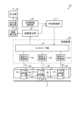
- FIG. 1 is a diagram showing the configuration of a linear conveyance system according to the first embodiment.
- the linear transport system 51 is a system that uses linear motors to move the movable parts 1P to 1R.
- the linear conveyance system 51 includes movable parts 1P to 1R, fixed parts (stators) 2a to 2c, a control device 50, a distance calculation part 9, an allowable distance holding part 10, and an escort control part 11. There is.
- the movable parts 1P to 1R each have a permanent magnet.
- the movable parts 1P to 1R move according to a moving magnetic field applied from the outside.
- the linear conveyance system 51 can change the moving direction of the movable parts 1P to 1R and the thrust generated to the movable parts 1P to 1R depending on the direction of the moving magnetic field and the magnetic field strength. Note that the number of movable parts may be two, or four or more.
- the movable parts 1P to 1R are arranged along the moving direction of the movable parts 1P to 1R.
- FIG. 1 shows a case where a movable part 1P is arranged next to the movable part 1Q, and a movable part 1R is arranged next to the movable part 1P.
- the fixed parts 2a to 2c are arranged along the path (transport path) along which the movable parts 1P to 1R move, that is, the moving direction.
- FIG. 1 shows a case where a fixing part 2b is arranged next to the fixing part 2a, and a fixing part 2c is arranged next to the fixing part 2b.
- the fixed parts 2a to 2c have coils for generating a moving magnetic field to drive the movable parts 1P to 1R.
- the fixed parts 2a to 2c individually drive each of the movable parts 1P to 1R by energizing the coils according to the position of each of the movable parts 1P to 1R.
- the fixed parts 2a to 2c can drive each of the movable parts 1P to 1R at arbitrary positions and speeds within a range where the movable parts 1P to 1R do not collide with each other.
- the fixed parts 2a to 2c have a holding mechanism that holds the movable parts 1P to 1R, and it is possible to drive the movable parts 1P to 1R along the fixed parts 2a to 2c without falling off.
- the fixing parts 2a to 2c are mechanically and continuously connected, and can form an arbitrary path. That is, by connecting the fixing parts 2a to 2c, it is possible to form a fixed conveyance path.
- the number of fixing parts may be two, or four or more. Further, the fixing part can be shaped to match the shape of the conveyance path, and can be shaped into a straight line, a curved line, or the like. Furthermore, the number of fixed parts and movable parts is not limited to the same number. Further, the positional relationship between the movable parts 1P to 1R and the fixed parts 2a to 2c is not fixed on a one-to-one basis. For example, the movable part 1P can move across the fixed parts 2a to 2c. Similarly, the movable parts 1Q and 1R can move across the fixed parts 2a to 2c.
- the stator control section 3a controls the fixed section 2a.
- Stator control section 3b controls fixing section 2b.
- the stator control section 3c controls the fixed section 2c.
- the stator control parts 3a to 3c include an inverter part (not shown) for energizing the coils of the fixed parts 2a to 2c, and a position detection part (not shown) to detect the position of each movable part 1P to 1R. has. Each inverter section energizes the coil and detects the energized current.
- the position detection unit detects the magnetic field emitted from the permanent magnets of the movable parts 1P to 1R using, for example, Hall sensors attached to the fixed parts 2a to 2c, and performs position detection based on the detected magnetic field.
- the stator control units 3a to 3c may detect the position of each of the movable parts 1P to 1R using any method. That is, the method of position detection is not limited to the method described in the first embodiment.
- the stator control sections 3a to 3c correspond one-to-one to the fixed sections 2a to 2c, respectively, and the correspondence relationship does not change during control.
- the controller section 4 independently drives and controls the movable sections 1P to 1R.
- the controller unit 4 generates current commands to the stator control units 3a to 3c based on the operation profile of each movable part 1P to 1R written by the user from an engineering tool or the like. That is, the controller section 4 generates a current command to the inverter section for driving the movable sections 1P to 1R according to the operation profile.
- the driving profile is defined by a driving program created by the user.
- controller unit 4 detects the positions of all the movable parts 1P to 1R in the linear conveyance system 51 by collecting the position information of each of the movable parts 1P to 1R acquired by the stator control parts 3a to 3c. .
- the controller section 4 can centrally control the entire movable sections 1P to 1R. Thereby, the controller section 4 can arbitrarily and individually control each of the movable parts 1P to 1R while constantly grasping the position and state of each of the movable parts 1P to 1R.
- controller unit 4 controls some of the movable parts of the movable parts 1P to 1R based on the operation profile for some of the movable parts, and controls the other movable parts of the movable parts 1P to 1R. Control may be performed based on 1R position information. For example, the controller unit 4 controls the movable part 1P based on the position information of the movable part 1P and the operation profile of the movable part 1P created in advance.
- controller unit 4 controls the movable unit 1Q based on the driving profile of the movable unit 1Q generated by the escort control unit 11 based on the position information of the movable units 1P and 1Q, and the position information of the movable unit 1Q. to control the movable part 1Q.
- controller unit 4 controls the movable unit 1R based on the driving profile of the movable unit 1R generated by the accompaniment control unit 11 based on the position information of the movable units 1P and 1R, and the position information of the movable unit 1R. to control the movable part 1R.
- the driving profile includes a position command. That is, the controller unit 4 controls the movable parts 1P to 1R based on the position command of the driving profile and the position information of the movable parts 1P to 1R.
- a current command to the stator control section 3b for controlling the movable section 1P is created.
- the controller unit 4 also supplies current to the stator control units 3a, 3c for controlling the movable parts 1Q, 1R based on a position command (second position command) of an operation profile created by the user, for example. Create directives. Note that, for example, in the case of a positional relationship such that the movable part 1P is located at the boundary between the fixed parts 2b and 2c, the controller part 4 receives the position command (first position command) of the driving profile sent from the accompaniment control part 11.
- a current command to the stator control units 3b, 3c is created. Furthermore, in the case of a positional relationship such that the movable part 1Q is located at the boundary between the fixed parts 2a and 2b, for example, the controller part 4 operates based on the position command (second position command) of the driving profile created by the user. , creates a current command to the stator control units 3a, 3b. Further, the controller unit 4 sends position information indicating the positions of the movable parts 1P to 1R acquired by the stator control units 3a to 3c to the distance calculation unit 9.
- the movable parts 1P to 1R are controlled by the common controller part 4, so the movable parts 1P to 1R can be moved at high acceleration/deceleration.
- the movable parts 1P to 1R are controlled by the common controller part 4, there is no need for the movable part 1P to mount a sensor on itself, and the movement of the movable part 1R is controlled by its own sensor.
- the movement of the movable part 1P after detecting the movable part 1R with a sensor, so it is possible to suppress restrictions on the drive patterns of the movable parts 1Q and 1R.
- the distance calculation unit 9 calculates the distance between adjacent movable parts based on the position information of the movable parts 1P to 1R.
- the distance calculation unit 9 sends the calculated distance and position information of the movable parts 1P to 1R to the escort control unit 11.
- the permissible distance holding unit 10 stores a permissible range of distance between adjacent movable parts (permissible proximity range to be described later).
- the accompaniment control unit 11 is based on the distance between adjacent movable parts calculated by the distance calculation unit 9, the permissible proximity range stored in the permissible distance holding unit 10, and the position information of the movable parts 1P to 1R. , a position command specifying the position of at least one of the movable parts 1P to 1R is generated.
- the accompaniment control unit 11 generates a position command so that adjacent movable parts do not collide and cables 8a and 8b connecting the adjacent movable parts do not come off.
- An example of the escort control unit 11 is a motion controller. Details of the distance calculation section 9, allowable distance holding section 10, and escort control section 11 will be described later. Note that the linear transport system 51 may include three or more movable parts.
- the uses of the linear conveyance system 51 are broadly divided into conveyance uses and processing uses.
- a linear conveyance system as a comparative example will be explained.
- the purpose is to move the work to a target position with the work to be conveyed loaded on the movable part. After the workpiece reaches the target position, it is discharged or processed by an externally installed device.
- the movable part is only loaded with workpieces, and there is no need to load a processing device on the movable part for discharging or processing the workpieces loaded on the movable part. No communication is required. Therefore, the load weight applied to the movable part is only the weight of the workpiece, and almost all of the output of the movable part can be used for moving the workpiece.
- the linear conveyance system of the comparative example when used for processing, the purpose is to mount a processing device on the movable part and perform processing while moving the movable part.
- power supply and communication are required to operate electrical equipment such as a motor incorporated in the processing device. Therefore, the output when a power source and the like are mounted on the same movable part is used not only to move the processing device but also to move the power supply device and the communication device. Therefore, when the linear conveyance system of the comparative example is used for processing purposes, the output conditions are stricter than when it is used for conveyance purposes.
- the load weight applied to the movable part is the weight of the movable part including the weight of objects loaded on the movable part, such as processing equipment.
- the movable part on which the processing devices 21 and 22 are mounted and the movable part on which an output device such as a power supply device is mounted are separated. That is, in the linear conveyance system 51, the movable part on which the processing devices 21 and 22 are mounted and the movable part on which the output device is mounted are separate movable parts.
- the output device are a power supply device that outputs power and a communication device that outputs data. Note that the communication device may receive data from the processing devices 21 and 22.
- the processing devices 21 and 22 are devices used to process a workpiece.
- Examples of the processing devices 21 and 22 are drive devices (servo motors, servo amplifiers, arms), proximity sensors, cameras, robots, measuring devices, inspection devices, and the like. Note that the processing of the workpiece includes steps performed on the workpiece until the workpiece is completed, and includes, for example, fixing, moving, deforming, and inspecting the workpiece.
- An example of the drive device is a transport device that slides and transports a semiconductor wafer.
- An example of a communication device is a device (controller) that controls a processing device.
- an output device such as a power supply device or a communication device is mounted on the movable section 1P
- a processing device 21 is mounted on the movable section 1Q
- a processing device 22 is mounted on the movable section 1R.
- the movable part 1P and the movable part 1Q are connected by a cable 8a
- the movable part 1P and the movable part 1R are connected by a cable 8b.
- power or data is sent from the output device mounted on the movable part 1P to the processing devices 21 and 22 mounted on the movable parts 1Q and 1R.
- the movable part 1P on which the output device is mounted is the output movable part
- the movable parts 1Q and 1R on which the processing devices 21 and 22 are mounted are the processing movable parts.
- the output device of the movable part 1P can also supply power, send and receive data, etc. to other movable parts (not shown) connected to the movable parts 1Q and 1R by cables (not shown). I can do it.
- the output device of the movable part 1P supplies power, transmits and receives data, etc. via the movable parts 1Q and 1R.
- the output device of the movable part 1P can supply power, send and receive data, etc. to any device connected directly or indirectly with a cable.
- data communication may be performed by wireless communication between the movable parts 1P to 1R.
- the power supply device or the communication device is mounted on the movable part 1P, since it is connected to the processing devices 21 and 22 by cables 8a and 8b, so that there is no problem even if they are mechanically separated. . That is, an output device that outputs electrical energy, data, etc. is mounted on the movable part 1P, which is the output movable part.
- processing devices 21, 22, etc. that receive electrical energy, data, etc. output from the movable part 1P are mounted on the movable parts 1Q, 1R, which are the processing movable parts.
- the processing devices 21 and 22 mounted on the movable parts 1Q and 1R may transmit data to a communication device etc. mounted on the movable part 1P. That is, data may be transmitted and received between devices mounted on the movable parts 1P to 1R.
- the controller unit 4 causes the movable part 1P, which is the output movable part, to follow the movable parts 1Q and 1R, which are the processing movable parts, so that the movable parts 1P to 1R are maintained at appropriate positions.
- the output device can supply power or data to the processing devices 21, 22.
- the output device can be mounted on the movable section 1P that is separate from the movable sections 1Q and 1R on which the processing devices 21 and 22 are mounted, so that the processing devices 21 and 22 can be made lighter. Therefore, the linear conveyance system 51 can improve the positioning control performance of the movable parts 1Q and 1R on which the processing devices 21 and 22 are mounted.
- the contactless power supply device that supplies power to the processing devices 21 and 22 can be connected in a contactless manner to the primary power source 5 that supplies power.
- This contactless power supply device includes a pickup core 6 that receives power from a primary power source 5 and a regulator 7 that regulates the output voltage from the pickup core 6.
- the power supply device may be a contact power supply device.
- the power supply device is connected to the primary power supply 5 via a cable. Further, the power supply device may be a battery.
- the primary power source 5 is fixedly arranged along the trajectory of the pickup core 6, and the pickup core 6 and regulator 7 are fixed to and move on the movable part 1P, which is the output movable part.
- the movable part 1P is equipped with only the pickup core 6 and the regulator 7, for example. If only these are mounted, the movable part 1P can move within the range of the loading capacity of the movable part 1P.
- the linear conveyance system 51 has only the processing devices 21 and 22 mounted on the movable portions 1Q and 1R, and the processing devices 21 and 22 are powered by a power supply device mounted on the movable portion 1P and cables 8a and 8b. supply That is, there is no need to mount the pickup core 6 and the regulator 7 on the movable parts 1Q, 1R. As a result, in the linear conveyance system 51, even when the processing devices 21 and 22 are operated while the movable portions 1Q and 1R are moving, only the processing devices 21 and 22 need be mounted on the movable portions 1Q and 1R. It is possible to prevent an increase in the load weight applied to 1Q and 1R.
- the output movable section on which the output device is mounted is lighter and smaller than the processing movable section on which the processing devices 21 and 22 are mounted.
- the load weight applied to the output movable section on which the output device is mounted is smaller than the processing movable section on which the processing devices 21 and 22 are mounted.
- the output movable section may be configured such that, for example, the number of permanent magnets in the output movable section is smaller than the number of permanent magnets in the processing movable section, or the size of the permanent magnets in the output movable section is made smaller than the size of the permanent magnets in the processing movable section.
- the weight of the output movable section may be made lighter than the weight of the processing movable section, and the size of the output movable section may be made smaller than the size of the processing movable section.
- the linear conveyance system 51 can reduce the cost of the output movable section and reduce the area occupied by the output movable section on the conveyance path.
- the linear conveyance system 51 can move the movable parts 1Q and 1R at high acceleration and deceleration. Furthermore, in the linear conveyance system 51, since the load weight applied to the movable parts 1Q, 1R is reduced, the performance of positioning control of the movable parts 1Q, 1R can be improved. Since the linear conveyance system 51 can control the movable parts 1Q, 1R with high acceleration/deceleration and high accuracy, it is possible to suppress restrictions on the drive patterns of the movable parts 1Q, 1R.
- Control of processing in the processing devices 21 and 22 is executed by, for example, a higher-level controller higher than the controller unit 4.
- the host controller may control the processing devices 21 and 22 through wired communication, or may control the processing devices 21 and 22 through wireless communication.
- the host controller collects various data from the processing devices 21 and 22 and stores it in a storage device or the like.
- the upper controller may control the processing devices 21 and 22 based on data collected from the processing devices 21 and 22.
- control of processing in the processing devices 21 and 22 may be performed by the controller unit 4.
- the controller unit 4 may control the processing devices 21 and 22 through wired communication, or may control the processing devices 21 and 22 through wireless communication.
- one or more processing devices can be connected to one output device.
- the controller section 4 of the linear conveyance system 51 controls each of the movable sections 1P to 1R so that the cables 8a and 8b do not come off.
- the controller unit 4 controls the position of a combination of two movable parts 1P and 1Q.
- the movable part 1P is an output movable part equipped with a power supply device
- the movable part 1Q is a processing movable part equipped with a processing device 21.
- the controller unit 4 collects the position information of the movable parts 1P and 1Q acquired by the stator control units 3a and 3b.
- the controller section 4 sends the collected position information of 1P and 1Q to the distance calculation section 9.
- the distance calculation unit 9 calculates the difference in the positions of the movable parts 1P and 1Q. That is, the distance calculation unit 9 calculates the distance between the movable parts 1P and 1Q (hereinafter sometimes referred to as the distance between movable parts). For example, if the position of the movable part 1P is Ap and the position of the movable part 1Q is Aq, the distance calculation unit 9 calculates
- the allowable distance holding unit 10 holds an allowable proximity range that is the allowable proximity range (distance) between the movable parts 1P and 1Q. Specifically, the allowable distance holding unit 10 stores Min(Ap-Aq), which is the minimum allowable value of
- Min(Ap-Aq) is determined, for example, when the movable parts 1P and 1Q are too close to each other and the cable 8a interferes with each other, or when the cable 8a is bent and the cable 8a is connected to the power supply device, the processing device 21, the movable parts 1P and 1Q, Or, it is set assuming a situation where the primary side power supply 5 is contacted.
- Max (Ap-Aq) is set assuming a situation where, for example, the movable parts 1P and 1Q are too far apart from each other, causing the cable 8a to come off, the cable connector part to be damaged, and the cable 8a to be damaged. Ru.
- the controller section 4 controls the movable section 1P so that
- the escort control unit 11 controls the operation of the movable part 1P based on the position information of the movable parts 1P and 1Q so that
- This operation profile includes a position command to the movable part 1P.
- the escort control unit 11 sends the generated driving profile to the controller unit 4. Note that the operation profile of the movable part 1P may be created by the user in advance.
- the controller unit 4 controls the position of the movable part 1Q according to the position command of the driving profile set by the user, and controls the position of the movable part 1P according to the position command of the driving profile sent from the escort control part 11. This allows the controller section 4 to appropriately control the movable sections 1P and 1Q while maintaining the connection of the cable 8a.
- the linear conveyance system 51 can control the positions of the movable parts 1P to 1R in the same way as in the case of a combination of two movable parts 1P and 1Q.
- the controller section 4 controls the positions of a combination of three movable sections 1P to 1R.
- the movable part 1P is an output movable part equipped with a power supply device
- the movable parts 1Q and 1R are processing movable parts equipped with processing devices 21 and 22.
- the controller unit 4 collects the position information of the movable parts 1P to 1R acquired by the stator control units 3a to 3c.
- the controller section 4 sends the collected position information of 1P to 1R to the distance calculation section 9.
- the distance calculation unit 9 calculates the difference between the positions of the movable parts 1P and 1Q and the difference between the positions of the movable parts 1P and 1R. That is, the distance calculation unit 9 calculates the inter-movable part distance between the movable parts 1P and 1Q, and the inter-movable part distance between the movable parts 1P and 1R. For example, if the position of the movable part 1P is Ap, the position of the movable part 1Q is Aq, and the position of the movable part 1R is Ar, the distance calculation section 9 calculates the absolute value difference between the positions of the movable parts 1P and 1Q.
- the distance calculation unit 9 sends the calculated distance between the movable parts to the escort control unit 11.
- the allowable distance holding unit 10 holds the allowable proximity range between the movable parts 1P and 1Q and the allowable proximity range between the movable parts 1P and 1R. Specifically, the allowable distance holding unit 10 stores Min(Ap-Aq), which is the minimum allowable value of
- the allowable distance holding unit 10 also stores Min(Ap-Ar), which is the minimum allowable value of
- Min (Ap-Ar), Max (Ap-Ar), and allowable proximity range Rng (Ap-Ar) is Min (Ap-Ar) ⁇ Rng (Ap-Ar) ⁇ Max (Ap-Ar). .
- Min(Ap-Ar) is, for example, when the movable parts 1P and 1R are too close to each other and the cable 8b interferes with each other, or when the cable 8b is bent and the cable 8b is connected to the power supply device, the processing device 22, the movable parts 1P and 1R, Or, it is set assuming a situation where the primary side power supply 5 is contacted.
- Max (Ap-Ar) is set assuming a situation where, for example, the movable parts 1P and 1R are too far apart, causing the cable 8b to come off, the cable connector to be damaged, and the cable 8b itself to be damaged. Ru.
- the controller unit 4 is configured such that
- the movable part 1P is controlled so as not to deviate from the inside. It is the movable parts 1Q and 1R on which the processing devices 21 and 22 are mounted that need to be moved under accurate positioning control. Therefore, the controller unit 4 applies position commands to the movable parts 1Q and 1R without changing the driving profile set by the user in advance.
- the accompaniment control unit 11 determines that
- This operation profile includes a position command to the movable part 1P.
- the escort control unit 11 sends the generated driving profile to the controller unit 4. Note that the operation profile of the movable part 1P may be created by the user in advance.
- the allowable proximity ranges Rng(Ap-Aq) and Rng(Ap-Ar) may be simply referred to as allowable proximity ranges.
- the controller unit 4 controls the positions of the movable parts 1Q and 1R according to the position command of the driving profile set by the user, and controls the position of the movable part 1P according to the position command of the driving profile sent from the escort control part 11. . This allows the controller section 4 to appropriately control the movable sections 1P to 1R while maintaining the connection between the cables 8a and 8b.
- the linear conveyance system 51 can control the positions of the four or more movable parts as in the case of a combination of three movable parts 1P to 1R.
- the controller part 4 controls the position of the machining movable part according to the position command of the operation profile set by the user, and controls the position of the machining movable part according to the position command of the operation profile set by the user, and controls the operation sent from the escort control part 11.
- the position of the output movable part is controlled according to the position command of the profile.
- the load weight applied to the movable part 1P and the load weight applied to the movable parts 1Q and 1R may be different. For example, if the load weight of the movable part 1P, which is the output movable part, is greater than the load weight of the movable parts 1Q, 1R, which are the processing movable parts, the acceleration/deceleration of the movable part 1P cannot follow the movable parts 1Q, 1R. There may be a case where the permissible proximity ranges Rng (Ap-Aq) and Rng (Ap-Ar) are deviated from.
- the output movable part cannot physically follow the movement of the processing movable part, and the allowable proximity range Rng (Ap-Aq) , Rng(Ap-Ar).
- the allowable proximity range Rng (Ap-Aq) , Rng(Ap-Ar).
- the accompaniment control unit 11 falls outside the allowable proximity range, it outputs a signal (outside-tolerance signal) indicating that it falls outside the allowable proximity range to the controller unit 4 and the like.
- the controller unit 4 stops the movable parts 1P to 1R, etc., for example. Further, the controller unit 4 or the higher-level controller stops the power supply device, the processing devices 21, 22, etc., for example. Further, the controller unit 4 may perform a protection operation such as moving each of the movable parts 1P to 1R so that the proximity range between the movable parts 1P to 1R falls within an allowable value. Further, the controller unit 4 may change the driving pattern to one that does not deviate from the allowable proximity range. In this case, the driving program in which the driving profile is defined by the user is changed. In this manner, the controller unit 4 prevents processing or the like from being performed in a state outside the permissible proximity range.
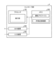
- FIG. 2 is a diagram illustrating an example of a hardware configuration that implements a controller section included in the control device according to the first embodiment.
- the controller unit 4 can be realized by an input device 300, a processor 100, a memory 200, and an output device 400.
- An example of the processor 100 is a CPU (Central Processing Unit, also referred to as a central processing unit, a processing unit, an arithmetic unit, a microprocessor, a microcomputer, or a DSP (Digital Signal Processor)) or a system LSI (Large Scale Integration).
- Examples of the memory 200 are RAM (Random Access Memory) and ROM (Read Only Memory).
- the controller unit 4 is realized by the processor 100 reading and executing a computer-executable control program for executing the operations of the controller unit 4 stored in the memory 200.
- the control program which is a program for executing the operations of the controller section 4, can also be said to cause the computer to execute the procedures or methods of the controller section 4.
- the control program executed by the controller unit 4 has a module configuration including an execution unit that executes various processes, and the execution unit is loaded onto the main storage and the execution unit is generated on the main storage.
- the input device 300 receives position information of the movable parts 1P to 1R from the stator control units 3a to 3c and sends it to the processor 100. Furthermore, the input device 300 receives a driving profile including a position command from the escort control unit 11 and sends it to the processor 100.
- the memory 200 stores driving profiles, allowable proximity ranges, etc.
- the allowable proximity ranges here are the above-mentioned allowable proximity ranges Rng(Ap-Aq) and Rng(Ap-Ar). Furthermore, the memory 200 is used as a temporary memory when the processor 100 executes various processes.
- Output device 400 outputs a current command to stator control units 3a to 3c. Further, the output device 400 outputs position information of the movable parts 1P to 1R to the distance calculation unit 9.
- the control program may be an installable or executable file stored in a computer-readable storage medium and provided as a computer program product. Further, the control program may be provided to the controller unit 4 via a network such as the Internet. Note that some of the functions of the controller unit 4 may be realized by dedicated hardware such as a dedicated circuit, and some may be realized by software or firmware.
- the hardware configuration shown in FIG. 2 may include the functions of the stator control units 3a to 3c. Further, the hardware configuration shown in FIG. 2 may include at least one function of the distance calculation section 9, the allowable distance holding section 10, and the escort control section 11.
- the linear conveyance system 51 is applied to, for example, a factory automated production line.
- production lines are production lines that assemble industrial products and the like, and production lines that package food.
- the linear conveyance system 51 individually controls the movable parts 1P to 1R arranged on the same conveyance path and constructs multiple processes on the same conveyance path, thereby reducing the installation area of equipment and shortening takt time. It is possible to realize reductions in energy consumption and flexibility in equipment design. Note that a battery may be mounted on the movable parts 1Q and 1R.
- the transport system 51 can also be applied to a system that performs high acceleration/deceleration. Further, since the movable parts 1P to 1R can be configured with the same specifications, the linear conveyance system 51 can be realized at low cost, and flexibility is increased when changing the system such as changing the production line.
- the linear conveyance system 51 of the first embodiment includes an output movable section in which an output device that outputs energy or data is mounted, and a processing movable section in which a processing device that receives energy or data from the output device is mounted.
- the controller section 4 independently controls the output movable section and the processing movable section.
- the linear conveyance system 51 can move the movable parts at high acceleration/deceleration while suppressing restrictions on the drive pattern of the movable parts (the output movable part and the processing movable part).
- Embodiment 2 Next, Embodiment 2 will be described using FIG. 3.
- the degree of deterioration of the cables 8a, 8b is predicted based on the operation of the cables 8a, 8b.
- FIG. 3 is a diagram showing the configuration of a linear conveyance system according to the second embodiment. Among the components in FIG. 3, the components that achieve the same functions as the linear conveyance system 51 of the first embodiment shown in FIG.
- the linear conveyance system 52 includes a bending calculation section 31, a deterioration degree calculation section 32, and an output section 33.
- the bending calculation unit 31 is connected to the distance calculation unit 9 and obtains the distance between movable parts from the distance calculation unit 9.
- the bending calculation unit 31 calculates the bending status (bending history) of the cables 8a, 8b based on the distance between the movable parts and the lengths of the cables 8a, 8b.
- the bending calculation section 31 sends the bending situation to the deterioration degree calculation section 32.
- the deterioration degree calculation unit 32 calculates the deterioration degree of the cables 8a and 8b based on the bending situation.
- the output unit 33 outputs the degree of deterioration of the cables 8a, 8b calculated by the deterioration degree calculation unit 32 to an external device such as a display device.
- the linear conveyance system 52 diagnoses the degree of deterioration of the cables 8a, 8b before the cables 8a, 8b are damaged, and notifies the user of the degree of deterioration of the cables 8a, 8b before the cables 8a, 8b are damaged. This allows the cables 8a, 8b to be replaced before they are damaged.
- Factors that influence the degree of deterioration of the cables 8a, 8b include the bending speed, bending radius, number of bends, etc. of the cables 8a, 8b.
- the cables 8a and 8b bend, so the bending radius of the connector part of the cables 8a and 8b becomes smaller, and when the movable parts 1P to 1R separate after that, the cable 8a and 8b bend.
- the bending calculation unit 31 calculates the bending speed, bending radius, and number of bendings based on the mechanical configuration of the linear conveyance system 52 and the proximity distance of the movable parts 1P to 1R.
- the proximity distance of each of the movable parts 1P to 1R is calculated by the distance calculation unit 9. That is, the distance calculating section 9 calculates the above-mentioned
- the bending calculation unit 31 calculates the bending status of the cables 8a and 8b based on the design information of the devices included in the linear transportation system 52 and the actual operation results of the devices included in the linear transportation system 52.
- the design information used by the bending calculation unit 31 when calculating the bending situation includes the connector parts of the devices connected to the cables 8a and 8b, the processing devices 21 and 22, the movable parts 1P to 1R, the fixed parts 2a to 2c, and the pickup. This is design information for the core 6, regulator 7, primary power supply 5, etc. Further, the operation results used by the bend calculation unit 31 when calculating the bending situation are the operation results of the cables 8a, 8b, and the like.
- the degree of deterioration calculation unit 32 calculates the degree of deterioration of the cables 8a and 8b based on the bending situation calculated by the bending calculation unit 31. The greater the degree of deterioration of the cables 8a, 8b, the closer the cables 8a, 8b are to the end of their service life. That is, as the degree of deterioration of the cables 8a and 8b increases, the remaining life of the cables 8a and 8b becomes shorter.
- the user calculates a deterioration degree calculation formula for the linear conveyance system 52 based on the durability test results of the cables 8a and 8b obtained from the cable manufacturer, the theoretical calculation results of durability, and the actual durability results of the cables 8a and 8b. Create it.
- the deterioration degree calculation unit 32 calculates the deterioration degree of the cables 8a and 8b by applying the bending situation to the deterioration degree calculation formula.
- the deterioration degree calculation unit 32 separately calculates the deterioration degree of the cable 8a and the deterioration degree of the cable 8b.
- the deterioration degree calculation unit 32 When the calculated degree of deterioration reaches a specified value, the deterioration degree calculation unit 32 outputs a deterioration arrival signal indicating that the degree of deterioration of the cable 8a or 8b has reached the specified value from the output unit 33 to an external device or the like. do.
- the deterioration reaching signal is a signal indicating that the cable 8a or the cable 8b will reach the end of its life within a specific period (one hour, one day, etc.).
- the specified values used by the deterioration degree calculation section 32 are stored in advance by the deterioration degree calculation section 32.
- This specified value is a value that allows the cables 8a, 8b to be replaced before the cables 8a, 8b reach the end of their service life.
- the specified value is, for example, a value at which the cables 8a and 8b reach the end of their lifespans when the linear conveyance system 52 continues to operate for a specific period of time. Therefore, the output unit 33 outputs the deterioration reaching signal a specific time before the cables 8a, 8b reach the end of their service life.
- the linear conveyance system 52 can prompt the user that it is necessary to replace the cables 8a, 8b before the cables 8a, 8b are damaged.
- the user replaces the cables 8a, 8b before they are damaged.
- the linear conveyance system 52 can prevent damage to the cables 8a and 8b during processing.
- the output unit 33 may output information indicating the degree of deterioration to an external device or the like before the degree of deterioration reaches a specified value. This allows the user to refer to the degree of deterioration of the cables 8a, 8b before reaching the specified value.
- controller section 4 of the linear transport system 52 has the same hardware configuration as the controller section 4 of the linear transport system 51.
- the memory 200 provided in the controller unit 4 of the linear conveyance system 52 stores an operation profile, an allowable proximity range, a calculation formula for the degree of deterioration, and the like.
- the linear conveyance system 52 calculates the bending state of the cables 8a, 8b, calculates the degree of deterioration of the cables 8a, 8b based on the bending state, and transmits the deterioration arrival signal to the external device. etc., it is possible to notify the user of the degree of deterioration of the cables 8a, 8b before the cables 8a, 8b are damaged.
- the output movable section equipped with a power supply device is the movable section 1P
- the processing movable section equipped with the processing devices 21 and 22 is the movable section 1Q
- An example in which a plurality of processing devices are connected to one output device has been described as 1R.
- the number of output movable parts and processing movable parts can be determined depending on the situation.
- the processing movable section on which the processing device is mounted is the movable section 1P
- the output movable section on which the output device is mounted is the movable section 1Q and 1R, so that one processing device can output multiple units. It is also possible to connect devices.
- the number of output movable parts and processing movable parts is arbitrary, and the number of processing devices connected to one output device and the number of output devices connected to one processing device can also be determined according to the situation. can.
Landscapes
- Engineering & Computer Science (AREA)
- Power Engineering (AREA)
- Physics & Mathematics (AREA)
- Chemical & Material Sciences (AREA)
- Combustion & Propulsion (AREA)
- Electromagnetism (AREA)
- Control Of Linear Motors (AREA)
- Linear Motors (AREA)
- Non-Mechanical Conveyors (AREA)
- Multi-Process Working Machines And Systems (AREA)
Priority Applications (5)
| Application Number | Priority Date | Filing Date | Title |
|---|---|---|---|
| CN202280082874.9A CN118401451B (zh) | 2022-06-01 | 2022-06-01 | 线性输送系统及控制装置 |
| DE112022005188.4T DE112022005188T5 (de) | 2022-06-01 | 2022-06-01 | Lineares Transportsystem und Steuervorrichtung |
| US18/722,048 US12195283B2 (en) | 2022-06-01 | 2022-06-01 | Linear conveyance system and control apparatus |
| PCT/JP2022/022296 WO2023233576A1 (ja) | 2022-06-01 | 2022-06-01 | リニア搬送システムおよび制御装置 |
| JP2022567026A JP7250225B1 (ja) | 2022-06-01 | 2022-06-01 | リニア搬送システムおよび制御装置 |
Applications Claiming Priority (1)
| Application Number | Priority Date | Filing Date | Title |
|---|---|---|---|
| PCT/JP2022/022296 WO2023233576A1 (ja) | 2022-06-01 | 2022-06-01 | リニア搬送システムおよび制御装置 |
Publications (1)
| Publication Number | Publication Date |
|---|---|
| WO2023233576A1 true WO2023233576A1 (ja) | 2023-12-07 |
Family
ID=85772949
Family Applications (1)
| Application Number | Title | Priority Date | Filing Date |
|---|---|---|---|
| PCT/JP2022/022296 Ceased WO2023233576A1 (ja) | 2022-06-01 | 2022-06-01 | リニア搬送システムおよび制御装置 |
Country Status (5)
| Country | Link |
|---|---|
| US (1) | US12195283B2 (https=) |
| JP (1) | JP7250225B1 (https=) |
| CN (1) | CN118401451B (https=) |
| DE (1) | DE112022005188T5 (https=) |
| WO (1) | WO2023233576A1 (https=) |
Cited By (1)
| Publication number | Priority date | Publication date | Assignee | Title |
|---|---|---|---|---|
| JP7638463B1 (ja) * | 2024-07-16 | 2025-03-03 | 三菱電機株式会社 | リニアモータ制御装置およびリニア搬送システム |
Citations (6)
| Publication number | Priority date | Publication date | Assignee | Title |
|---|---|---|---|---|
| JPS575659B2 (https=) * | 1974-05-22 | 1982-02-01 | ||
| JPH04141706A (ja) * | 1990-10-03 | 1992-05-15 | Fujitsu Ltd | 搬送装置 |
| JPH0717619A (ja) * | 1993-06-30 | 1995-01-20 | Fuji Xerox Co Ltd | 移動式電源供給装置 |
| JP2525163Y2 (ja) * | 1990-04-16 | 1997-02-05 | 力一 佐藤 | 移動式作業台を備えた工場施設 |
| JP3112577U (ja) * | 2005-05-20 | 2005-08-18 | 太陽技研工業株式会社 | 加工機械の防音装置 |
| JP2021528336A (ja) * | 2018-06-22 | 2021-10-21 | ベーウントエル・インダストリアル・オートメイション・ゲゼルシャフト・ミト・ベシュレンクテル・ハフツング | 長固定子リニアモーターのための運搬装置 |
Family Cites Families (11)
| Publication number | Priority date | Publication date | Assignee | Title |
|---|---|---|---|---|
| US4772837A (en) * | 1987-04-02 | 1988-09-20 | Jervis B. Webb Company | Apparatus and method for controlling linear motors |
| JP3367219B2 (ja) | 1994-08-31 | 2003-01-14 | 住友金属工業株式会社 | 熱間継目無管製造用マンドレルバー |
| JP2007004527A (ja) | 2005-06-24 | 2007-01-11 | Sharp Corp | 電源中継システム |
| JP2010115093A (ja) * | 2008-11-10 | 2010-05-20 | Toshiba Corp | 移動装置 |
| JP5791363B2 (ja) | 2011-05-10 | 2015-10-07 | 株式会社小松製作所 | 自走式ケーブル中継台車 |
| JP5305257B2 (ja) * | 2011-06-15 | 2013-10-02 | 株式会社安川電機 | 搬送システム |
| DE102012025323B4 (de) * | 2012-12-22 | 2025-07-31 | Festo Se & Co. Kg | Verfahren zum Betreiben einer Linearmotoranordnung und Linearmotoranordnung |
| JP6343476B2 (ja) * | 2014-04-08 | 2018-06-13 | 株式会社アイエイアイ | 搬送装置及び搬送システム |
| DE102016205513A1 (de) * | 2016-04-04 | 2017-10-05 | Robert Bosch Gmbh | Verfahren zum Transportieren eines Gutes, mehrdimensionaler Antrieb und Verarbeitungsvorrichtung |
| DE102018111715A1 (de) | 2018-05-16 | 2019-11-21 | Beckhoff Automation Gmbh | Lineares transportsystem und system zur kontaktlosen energie- und datenübertragung |
| DE102021124123A1 (de) | 2021-09-17 | 2023-03-23 | Beckhoff Automation Gmbh | Energieübertragung in einem linearen Transportsystem |
-
2022
- 2022-06-01 DE DE112022005188.4T patent/DE112022005188T5/de active Pending
- 2022-06-01 JP JP2022567026A patent/JP7250225B1/ja active Active
- 2022-06-01 CN CN202280082874.9A patent/CN118401451B/zh active Active
- 2022-06-01 US US18/722,048 patent/US12195283B2/en active Active
- 2022-06-01 WO PCT/JP2022/022296 patent/WO2023233576A1/ja not_active Ceased
Patent Citations (6)
| Publication number | Priority date | Publication date | Assignee | Title |
|---|---|---|---|---|
| JPS575659B2 (https=) * | 1974-05-22 | 1982-02-01 | ||
| JP2525163Y2 (ja) * | 1990-04-16 | 1997-02-05 | 力一 佐藤 | 移動式作業台を備えた工場施設 |
| JPH04141706A (ja) * | 1990-10-03 | 1992-05-15 | Fujitsu Ltd | 搬送装置 |
| JPH0717619A (ja) * | 1993-06-30 | 1995-01-20 | Fuji Xerox Co Ltd | 移動式電源供給装置 |
| JP3112577U (ja) * | 2005-05-20 | 2005-08-18 | 太陽技研工業株式会社 | 加工機械の防音装置 |
| JP2021528336A (ja) * | 2018-06-22 | 2021-10-21 | ベーウントエル・インダストリアル・オートメイション・ゲゼルシャフト・ミト・ベシュレンクテル・ハフツング | 長固定子リニアモーターのための運搬装置 |
Cited By (2)
| Publication number | Priority date | Publication date | Assignee | Title |
|---|---|---|---|---|
| JP7638463B1 (ja) * | 2024-07-16 | 2025-03-03 | 三菱電機株式会社 | リニアモータ制御装置およびリニア搬送システム |
| WO2026018307A1 (ja) * | 2024-07-16 | 2026-01-22 | 三菱電機株式会社 | リニアモータ制御装置およびリニア搬送システム |
Also Published As
| Publication number | Publication date |
|---|---|
| JPWO2023233576A1 (https=) | 2023-12-07 |
| CN118401451B (zh) | 2025-01-10 |
| JP7250225B1 (ja) | 2023-03-31 |
| CN118401451A (zh) | 2024-07-26 |
| US20240417182A1 (en) | 2024-12-19 |
| DE112022005188T5 (de) | 2024-08-08 |
| US12195283B2 (en) | 2025-01-14 |
Similar Documents
| Publication | Publication Date | Title |
|---|---|---|
| EP3482884B1 (en) | Mobile manipulator, method for controlling mobile manipulator, and program therefor | |
| US10370195B2 (en) | Method for operating a long stator linear motor | |
| US9098084B2 (en) | Transport carriage system and method for controlling running of transport carriage | |
| US10625948B2 (en) | Conveyance apparatus, conveyance system, and method of controlling conveyance system | |
| US11396097B2 (en) | Teaching apparatus, robot system, and teaching method | |
| JP5956324B2 (ja) | 搬送基台及び搬送システム | |
| JP7250225B1 (ja) | リニア搬送システムおよび制御装置 | |
| JP6703018B2 (ja) | 作業ロボットシステム | |
| JP4842913B2 (ja) | 組み合わせ動作制御システム | |
| JP2021038068A (ja) | 加工システム、および物品の製造方法 | |
| JP2022044957A (ja) | 搬送システム、加工システム、物品の製造方法、搬送システムの制御方法、プログラムおよび記憶媒体 | |
| JP5633555B2 (ja) | ロボットシステム | |
| US12509305B2 (en) | Transport system | |
| KR102533338B1 (ko) | 와이어리스 밸브 매니폴드 | |
| JPWO2023233576A5 (https=) | ||
| US20190210215A1 (en) | Workpiece Processing System | |
| JP7114234B2 (ja) | 搬送システム及び加工システム | |
| CN120303200B (zh) | 输送系统 | |
| JP4636034B2 (ja) | 可動テーブルの制御装置およびそれを備えた可動テーブル装置 | |
| WO2026006946A1 (en) | Method and electronic device for use with magnetic controller, method and electronic device for use with robot controller, and corresponding robotic system | |
| KR20220028841A (ko) | 제조 공장 내 물품 반송 시스템에서 반송 차량의 장애물 탐지 방법 | |
| JP7638463B1 (ja) | リニアモータ制御装置およびリニア搬送システム | |
| WO2025026967A1 (en) | Autonomous mobile robot with a conveyor track | |
| WO2025095054A1 (ja) | 情報取得システム | |
| KR102280285B1 (ko) | 리니어 컨베이어 시스템 제어장치 |
Legal Events
| Date | Code | Title | Description |
|---|---|---|---|
| ENP | Entry into the national phase |
Ref document number: 2022567026 Country of ref document: JP Kind code of ref document: A |
|
| 121 | Ep: the epo has been informed by wipo that ep was designated in this application |
Ref document number: 22944863 Country of ref document: EP Kind code of ref document: A1 |
|
| WWE | Wipo information: entry into national phase |
Ref document number: 202280082874.9 Country of ref document: CN |
|
| WWE | Wipo information: entry into national phase |
Ref document number: 18722048 Country of ref document: US |
|
| WWE | Wipo information: entry into national phase |
Ref document number: 112022005188 Country of ref document: DE |
|
| WWG | Wipo information: grant in national office |
Ref document number: 202280082874.9 Country of ref document: CN |
|
| 122 | Ep: pct application non-entry in european phase |
Ref document number: 22944863 Country of ref document: EP Kind code of ref document: A1 |