WO2023233545A1 - 有線通信及び無線通信を用いた機械操作システム - Google Patents
有線通信及び無線通信を用いた機械操作システム Download PDFInfo
- Publication number
- WO2023233545A1 WO2023233545A1 PCT/JP2022/022199 JP2022022199W WO2023233545A1 WO 2023233545 A1 WO2023233545 A1 WO 2023233545A1 JP 2022022199 W JP2022022199 W JP 2022022199W WO 2023233545 A1 WO2023233545 A1 WO 2023233545A1
- Authority
- WO
- WIPO (PCT)
- Prior art keywords
- wireless
- wired
- machine
- robot
- operating device
- Prior art date
- Legal status (The legal status is an assumption and is not a legal conclusion. Google has not performed a legal analysis and makes no representation as to the accuracy of the status listed.)
- Ceased
Links
Images






Classifications
-
- B—PERFORMING OPERATIONS; TRANSPORTING
- B25—HAND TOOLS; PORTABLE POWER-DRIVEN TOOLS; MANIPULATORS
- B25J—MANIPULATORS; CHAMBERS PROVIDED WITH MANIPULATION DEVICES
- B25J9/00—Program-controlled manipulators
- B25J9/16—Program controls
- B25J9/1656—Program controls characterised by programming, planning systems for manipulators
-
- H—ELECTRICITY
- H04—ELECTRIC COMMUNICATION TECHNIQUE
- H04L—TRANSMISSION OF DIGITAL INFORMATION, e.g. TELEGRAPHIC COMMUNICATION
- H04L63/00—Network architectures or network communication protocols for network security
- H04L63/08—Network architectures or network communication protocols for network security for authentication of entities
-
- G—PHYSICS
- G05—CONTROLLING; REGULATING
- G05B—CONTROL OR REGULATING SYSTEMS IN GENERAL; FUNCTIONAL ELEMENTS OF SUCH SYSTEMS; MONITORING OR TESTING ARRANGEMENTS FOR SUCH SYSTEMS OR ELEMENTS
- G05B19/00—Program-control systems
- G05B19/02—Program-control systems electric
- G05B19/42—Recording and playback systems, i.e. in which the program is recorded from a cycle of operations, e.g. the cycle of operations being manually controlled, after which this record is played back on the same machine
-
- H—ELECTRICITY
- H04—ELECTRIC COMMUNICATION TECHNIQUE
- H04L—TRANSMISSION OF DIGITAL INFORMATION, e.g. TELEGRAPHIC COMMUNICATION
- H04L63/00—Network architectures or network communication protocols for network security
- H04L63/18—Network architectures or network communication protocols for network security using different networks or channels, e.g. using out of band channels
-
- G—PHYSICS
- G05—CONTROLLING; REGULATING
- G05B—CONTROL OR REGULATING SYSTEMS IN GENERAL; FUNCTIONAL ELEMENTS OF SUCH SYSTEMS; MONITORING OR TESTING ARRANGEMENTS FOR SUCH SYSTEMS OR ELEMENTS
- G05B2219/00—Program-control systems
- G05B2219/30—Nc systems
- G05B2219/33—Director till display
- G05B2219/33192—Radio link, wireless
-
- G—PHYSICS
- G05—CONTROLLING; REGULATING
- G05B—CONTROL OR REGULATING SYSTEMS IN GENERAL; FUNCTIONAL ELEMENTS OF SUCH SYSTEMS; MONITORING OR TESTING ARRANGEMENTS FOR SUCH SYSTEMS OR ELEMENTS
- G05B2219/00—Program-control systems
- G05B2219/30—Nc systems
- G05B2219/36—Nc in input of data, input key till input tape
- G05B2219/36159—Detachable or portable programming unit, display, pc, pda
Definitions
- the present invention relates to a machine operation system using wired communication and wireless communication.
- a teaching operation device In order to manually operate a robot or industrial machine, a teaching operation device called a teaching pendant is used which is connected to a control device of the robot or industrial machine. Using the teaching operation device, a worker can register or edit an operation program related to a robot or industrial machine, set conditions, display the status, and teach the robot or industrial machine.
- the teaching operation device is provided with safety switches such as an enable switch and an emergency stop button in order to avoid unexpected movements of the robot or machine tool and ensure the safety of surrounding machines and workers.
- teaching and operating devices are being used to manually operate robots and industrial machinery using general-purpose information terminals such as tablets, rather than dedicated hardware for teaching and operating devices. , it is necessary to provide a safety switch in such a teaching operation device as well.
- an industrial robot operating device is an industrial robot operating device that outputs an operating signal for operating a robot based on an input operation by a worker and supplies it to a robot controller, and has a touch panel section for display and input, and the touch panel A portable operation terminal that outputs the operation signal when a worker inputs the operation terminal; and a base member that is arranged such that the operation terminal is detachable and the touch panel section is exposed to the outside;
- the base member includes a grip portion that stands upright from a bottom plate facing the back surface of the operating terminal, and is gripped by the other hand when an operator performs an input operation with one hand, and a state in which the grip portion is gripped. and an enable switch provided at a position that can be operated by a hand holding the grip part, and further comprising a detection means for detecting that the operation terminal is placed on the base member.
- An operating device is known (for example, see Patent Document 1).
- a switch body that is wired to a robot controller that controls the drive of the robot and switches the control of the robot controller to an emergency stop state in response to a user's operation, and a switch body that is connected to a mobile terminal that accepts the user's operation.
- a mounting part for removably attaching the switch; and a mounting part provided at a position facing the lens of a camera included in the mobile terminal when the mounting part is attached to the mobile terminal, and an identification code for identifying the switch main body part to be attached to the camera.
- An emergency stop switch is known that includes an identification code section that is displayed in a photographable manner (for example, see Patent Document 2).
- a base member provided with a safety switch is attached to the general-purpose information terminal.
- a general-purpose information terminal is connected to the control device of a robot or industrial machine via wireless communication, but the base member is connected to the control device of the robot or industrial machine via wired communication to ensure safety. is common.
- the general-purpose information terminal and the base member are removable, if the general-purpose information terminal and the base member are separated and placed in different locations, a teaching worker holding the general-purpose information terminal can operate the safety switch on his own. Safety cannot be ensured because the safety switch cannot be operated voluntarily or may be operated by a third party other than the teaching worker.
- a machine operation system is connected to a control device of a robot or industrial machine via wireless communication, and wirelessly instructs the control device to operate the robot or industrial machine according to operation details.
- an operating device a wired operating device that is connected to the control device via wired communication and transmits a signal to the control device according to operation details; a first operation for the wired operating device; and a second operation for the wireless operating device.
- an authentication unit that validates the contents of the operation on the wireless operation device when these are executed simultaneously or in a predetermined order.
- safety can be ensured at low cost in a machine operation system that includes a general-purpose information terminal and a base member that includes a safety switch.
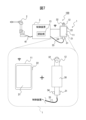
- FIG. 1 is a diagram illustrating a machine operating system according to an embodiment of the present disclosure.
- FIG. 1 is a flowchart illustrating an operation flow of a machine operating system according to an embodiment of the present disclosure.
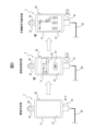
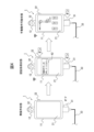
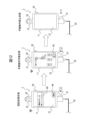
- FIG. 1 is a diagram illustrating a first form of a machine operating system according to an embodiment of the present disclosure. It is a figure explaining the 2nd form of the machine operation system according to one embodiment of the present disclosure. It is a figure explaining the 3rd form of the machine operation system according to one embodiment of the present disclosure. It is a figure explaining the 4th form of the machine operation system according to one embodiment of the present disclosure.
- FIG. 2 is a diagram illustrating an authentication button provided in a machine operation system according to an embodiment of the present disclosure.
- FIG. 1 is a diagram illustrating a machine operating system according to an embodiment of the present disclosure.
- the machine operated by the machine operation system 100 includes a robot or an industrial machine, and here, as an example, a case where a robot 2 is operated is shown. If the machine operated by the machine operation system 100 is an industrial machine, the term "robot 2" in the following description may be replaced with the term "industrial machine.” Industrial machines include, for example, machine tools, forging machines, injection molding machines, and the like.
- the robot 2 and the control device 3 are connected by a cable 41 (hereinafter referred to as the "robot cable 41") for wired communication, and the operation of the robot 2 is controlled by the control device 3.
- a processing unit (processor) is provided within the control device 3 .
- arithmetic processing devices include ICs, LSIs, CPUs, MPUs, and DSPs.
- the control device 3 having an arithmetic processing unit is, for example, a functional module realized by a computer program executed on a processor.
- each function for controlling the operation of the robot 2 can be realized by operating the arithmetic processing device according to the computer program.
- a computer program for executing the processing of the control device 3 may be provided in a form recorded on a computer-readable recording medium such as a semiconductor memory, a magnetic recording medium, or an optical recording medium.
- the control device may be realized as a semiconductor integrated circuit in which a computer program for realizing the function is written.
- a machine operation system 100 includes a wireless operation device 11, a wired operation device 12, and an authentication section 13.
- the teaching operation device 1 is configured by combining the wireless operation device 11 and the wired operation device 12.
- the wireless operation device 11 is, for example, a general-purpose information terminal such as a tablet or a smartphone.
- the wireless operation device 11 includes, for example, a touch panel 21 that has the functions of displaying a screen and accepting input operations.
- the wireless operation device 11 may have a display device that displays a screen and a physical operation button that accepts input operations.
- the wireless operation device 11 has a power button 22 for turning on the power of the wireless operation device 11. When the power button 22 is pressed once (turned on), the wireless operation device 11 is activated.
- the wireless operation device 11 has a battery (not shown) inside. The battery of the wireless operating device 11 is charged after the wireless operating device 11 is removed from the wired operating device 12 via a connector or a charging dock (charging stand).
- the wireless operation device 11 has a teaching application software program installed in its internal storage unit (not shown) for registering and editing operation programs related to the robot 2, setting conditions, displaying the status, teaching the robot 2, etc.
- the arithmetic processing unit (not shown) operates according to the teaching application software program installed in the storage unit, thereby realizing a wireless teaching operation function for operating (teaching) the robot 2. Examples of arithmetic processing devices include ICs, LSIs, CPUs, MPUs, and DSPs.
- the storage unit is configured of electrically erasable/recordable nonvolatile memory such as EEPROM (registered trademark), or random access memory that can be read and written at high speed such as DRAM or SRAM.
- the wireless operation device 11 is connected to the control device 3 of the robot 2 via wireless communication, and has a communication interface (not shown) for this purpose. The wireless operating device 11 instructs the control device 3 to operate the robot 2 according to the operation content of the wireless operating device 11 .
- short-range wireless communication is used as the wireless communication between the wireless operation device 11 and the control device 3.
- Short-range wireless communication refers to communication with a shorter communication distance than wide-area wireless communication, and specifically refers to communication with a communication distance of less than 10 meters, for example.
- various short-range wireless communications with short communication distances can be used, such as any communication standard established by IEEE, ISO, IEC, etc. (for example, Wi-Fi (registered trademark), Communication based on Bluetooth (registered trademark), ZigBee (registered trademark), etc.) is used.
- the illustrated example shows a case where communication based on Wi-Fi (registered trademark) is performed.
- DSRC dedicated short range communication
- RFID radio frequency identification
- the wired operating device 12 is connected to the control device 3 via wired communication, and has a communication interface (not shown) for this purpose.
- the wired operating device 12 and the control device 3 are connected via a cable 33 (hereinafter referred to as "teaching operating device cable 33").
- the wired operating device 12 includes a mounting base 30, an enable switch 31 as a safety switch, and an emergency stop button 32.
- the mounting base 30 is for attaching the wireless operating device 11 to the wired operating device 12 in a detachable manner.
- methods for attaching the wireless operating device 11 using the mounting base 30 include a method of gripping the wireless operating device 11 by pinching it with a spring mechanism provided on the wired operating device 12, a method of fastening the wireless operating device 11 with screws, and a method of wireless operation. There is a method of attaching the device 11 using an attaching member. Note that regardless of whether or not the wireless operating device 11 and the wired operating device 12 are mounted on the mounting base 30, there is no direct electrical connection or communication between the wireless operating device 11 and the wired operating device 12, and the wireless operating device 11 and the wired operating device 12 are not connected to each other. Communication between the device 11 and the wired operating device 12 will be performed via the control device 3.
- the enable switch 31 allows the control device 3 to control the operation of the robot 2 via the wireless operation device 11 while being pressed down (on), and when the enable switch 31 is released from being pressed down (on), the wireless operation device 11 This is a safety switch that disallows control of the operation of the robot 2 by the control device 3 via the control device 3.
- a signal corresponding to the operation content of the enable switch 31 is transmitted from the wired operating device 12 to the control device 3 via the teaching operating device cable 33. For example, while the enable switch 31 is not pressed, the robot 2 will not operate no matter what operation is performed via the wireless operation device 11. While the enable switch 31 is pressed down, the robot 2 can be operated via the wireless operation device 11.
- the emergency stop button 32 is a safety switch that instructs the control device 3 to make an emergency stop of the robot 2.
- an emergency stop signal is transmitted from the wired operating device 12 to the control device 3 via the teaching operating device cable 33, and in response to this, the robot 2 makes an emergency stop.
- the authentication unit 13 is provided within the control device 3.
- the authentication unit 13 may be provided within the wireless operating device 11 or the wired operating device 12.
- the first operation on the wired operating device 12, the second operation on the wireless operating device 11, and the third operation described later are operations related to authentication in the machine operating system 100, and are normal teaching using the wireless operating device 11. Although these operations are basically distinguished from normal safety operations using the safety switch of the wired operating device 12, there are some operations that overlap.
- the wireless operating device 11 When the wired operating device 12 and the wireless operating device 11 are in a non-operating state, the wireless operating device 11 does not instruct the control device 3 to operate the robot 2.
- the authentication unit 13 performs a first operation on the wired operation device 12 and a second operation on the wireless operation device 11 simultaneously or in a predetermined order after the wired operation device 12 and the wireless operation device 11 are in a non-operation state. If so, the contents of the operation on the wireless operation device 11 are enabled.
- the content of the operation on the wireless operation device 11 is validated by executing the first operation on the wired operation device 12 and the second operation on the wireless operation device 11 at the same time or in a predetermined order, authentication is performed.
- the unit 13 invalidates the content of the operation on the wireless operating device 11. Note that the forms of operation on the wired operating device 12 and wireless operating device 11 necessary for authentication by the authentication unit 13 will be described later.
- FIG. 2 is a flowchart showing the operation flow of the machine operating system according to an embodiment of the present disclosure.
- the wireless operating device 11 does not instruct the control device 3 to operate the robot 2.
- step S102 the authentication unit 13 determines whether the first operation on the wired operation device 12 has been performed based on the signal received from the wired operation device 12. The process of step S102 is repeatedly executed at a predetermined period. In step S102, if it is determined that the first operation on the wired operating device 12 has been executed, the process advances to step S103, and if it is not determined that the first operation on the wired operating device 12 has been executed, the process returns to step S101. .
- step S103 the authentication unit 13 determines whether the second operation on the wireless operation device 11 has been performed based on the signal received from the wireless operation device 11.
- the process of step S103 is repeatedly executed at a predetermined cycle.
- step S109 the authentication unit 13 performs the first operation on the wired operating device 12 based on the signal received from the wired operating device 12. Determine whether the operation is completed. The process of step S109 is repeatedly executed at a predetermined cycle. In step S109, if it is determined that the first operation on the wired operating device 12 has been completed, the process returns to step S101, and if it is not determined that the first operation on the wired operating device 12 has been completed, the process returns to step S103. .
- step S103 If it is determined in step S103 that the second operation on the wireless operation device 11 has been performed, the process advances to step S104.
- step S104 the authentication unit 13 determines whether the first operation on the wired operation device 12 is completed based on the signal received from the wired operation device 12. The process of step S104 is repeatedly executed at a predetermined period. In step S104, if it is determined that the first operation on the wired operating device 12 has been completed, the process returns to step S101, and if it is not determined that the first operation on the wired operating device 12 has been completed, the process proceeds to step S105. .
- step S104 may be omitted.
- step S104 if it is determined in step S103 that the second operation on the wireless operation device 11 has been performed, the process advances to step S105. That is, in an example in which step S104 is omitted, step S105 is executed by executing the first operation once in step S102 and executing the second operation once in step S103.
- step S105 the authentication unit 13 validates the operation details for the wireless operation device 11. This allows the operator to manually operate the robot 2 using the wireless operating device 11, such as teaching the robot 2 (manual operation), registering or editing an operation program regarding the robot 2, or setting conditions.
- the control device 3 controls the operation of the robot 2 (step S106).
- step S106 while the enable switch 31 is pressed, the robot 2 can be operated via the wireless operation device 11, and when the emergency stop button 32 is pressed, the robot 2 can be operated. Make an emergency stop.
- step S107 the authentication unit 13 determines whether the first operation on the wired operation device 12 has been completed based on the signal received from the wired operation device 12. The process of step S107 is repeatedly executed at a predetermined period. In step S107, if it is determined that the first operation on the wired operating device 12 has been completed, the process proceeds to step S108, and if it is not determined that the first operation on the wired operating device 12 has been completed, the process returns to step S106. .
- step S107 may be omitted.
- step S107 for example, after a predetermined period of time has elapsed from the start of execution of step S105, the process automatically proceeds to step 108, and the authentication unit 13 invalidates the operation content on the wireless operation device 11. It's okay.
- step S107 If it is determined in step S107 that the first operation on the wired operating device 12 has been completed, the authentication unit 13 invalidates the content of the operation on the wireless operating device 11 in step S108.
- FIG. 3 is a diagram illustrating a first form of a machine operating system according to an embodiment of the present disclosure.
- the first operation on the wired operation device 12 is an operation of pressing the enable switch 31, and the second operation on the wireless operation device 11 is an OK button that is an activation button displayed on the touch panel 21. The operation is to press 51.
- the wireless operating device 11 when the wired operating device 12 and the wireless operating device 11 are in a non-operating state, the wireless operating device 11 does not instruct the control device 3 to operate the robot 2. .
- the first operation of pressing down the enable switch 31 of the wired operation device 12 is performed after the wired operation device 12 and the wireless operation device 11 are in a non-operated state (Yes in step S102 in FIG. 2), authentication is performed.
- a display item 61 prompting the execution of a second operation such as "Please press the OK button" is displayed on the touch panel 21, which is a display of the wireless operation device 11.
- An OK button 51 is displayed.
- step S105 and step S106 a manual operation in which the operation contents for the wireless operation device 11 become effective. Transition to a possible state (step S105 and step S106).
- the manual operation enabled state when the teaching application software program is started, a manual operation screen for the robot 2 based on the teaching application software program that controls the control device 3 is displayed on the touch panel 21 . While the enable switch 31 is pressed down, the robot 2 can be manually operated using the wireless operation device 11 (touch panel 21 thereof).
- the enable switch 31 is turned off in the manual operation enabled state (Yes in step S107 in FIG. 2), the operation details for the wireless operation device 11 are invalidated (step S108 in FIG. 2), and the control device 3 via the wireless operation device 11 is disabled. Control of the operation of the robot 2 by the user is disallowed, and manual operation of the robot 2 using the wireless operation device 11 (touch panel 21 thereof) becomes impossible.
- FIG. 4 is a diagram illustrating a second form of the machine operation system according to an embodiment of the present disclosure.
- the first operation on the wired operation device 12 is an operation of pressing the enable switch 31, and the second operation on the wireless operation device 11 is the operation of pressing a hardware switch provided on the wireless operation device 11.
- the operation is as follows.
- the power button 22 is the hardware switch pressed in the second operation, but for example, pressing the volume button (not shown) may also be used as the second operation.
- the wireless operating device 11 when the wired operating device 12 and the wireless operating device 11 are in a non-operating state, the wireless operating device 11 does not instruct the control device 3 to operate the robot 2. .
- the first operation of pressing down the enable switch 31 of the wired operation device 12 is performed after the wired operation device 12 and the wireless operation device 11 are in a non-operated state (Yes in step S102 in FIG. 2)
- authentication is performed.
- a display item 62 prompting the execution of a second operation such as "Please press the power button" is displayed on the touch panel 21, which is a display of the wireless operation device 11. be done. Note that the display of the display item 62 may be omitted.
- Step S105 and Step S106 When the power button 22 is pressed once as a second operation while holding down the enable switch 31 (Yes in step S103 in FIG. 2), the state shifts to a state in which the operation contents for the wireless operation device 11 become valid ( Step S105 and Step S106).
- the manual operation enabled state when the teaching application software program is started, a manual operation screen for the robot 2 based on the teaching application software program that controls the control device 3 is displayed on the touch panel 21 . After this, while the enable switch 31 is pressed down, the robot 2 can be manually operated using the wireless operation device 11 (touch panel 21 thereof).
- the enable switch 31 is turned off in the manual operation enabled state (Yes in step S107 in FIG. 2), the operation contents for the wireless operation device 11 are invalidated (step S108 in FIG. 2), and the control device 3 via the wireless operation device 11 is disabled. Control of the operation of the robot 2 by the user is disallowed, and manual operation of the robot 2 using the wireless operation device 11 (touch panel 21 thereof) becomes impossible.
- FIG. 5 is a diagram illustrating a third form of the machine operation system according to an embodiment of the present disclosure.
- the first operation on the wired operating device 12 is an operation of pressing the enable switch 31, and the second operation on the wireless operating device 11 is to control the control device 3 displayed on the touch panel 21. This is an operation of pressing (touching) the startup icon 52 to start the teaching application software program.
- the wireless operating device 11 when the wired operating device 12 and the wireless operating device 11 are in a non-operating state, the wireless operating device 11 does not instruct the control device 3 to operate the robot 2. .
- the first operation of pressing down the enable switch 31 of the wired operation device 12 is performed after the wired operation device 12 and the wireless operation device 11 are in a non-operated state (Yes in step S102 in FIG. 2), authentication is performed.
- a startup icon 52 for starting a teaching application software program for controlling the control device 3 is displayed on the touch panel 21, which is a display of the wireless operation device 11. .
- icons for starting other application software programs may be displayed on the touch panel 21.
- step S105 and S106 the teaching application software program is activated, and A transition is made to a manual operable state in which the operation details for the wireless operation device 11 become valid (steps S105 and S106).
- the manual operation enabled state a screen for manual operation of the robot 2 based on a teaching application software program that controls the control device 3 is displayed on the touch panel 21 .
- the robot 2 can be manually operated using the wireless operation device 11 (touch panel 21 thereof).
- step S108 in FIG. 2 the operation contents for the wireless operation device 11 are invalidated (step S108 in FIG. 2), and the control device 3 via the wireless operation device 11 is disabled. Control of the operation of the robot 2 by the user is disallowed, and manual operation of the robot 2 using the wireless operation device 11 (touch panel 21 thereof) becomes impossible.
- FIG. 6 is a diagram illustrating a fourth form of the machine operation system according to an embodiment of the present disclosure.
- the first operation on the wired operating device 12 is an operation of pressing the enable switch 31, and the second operation on the wireless operating device 11 is an operation of moving the position and/or attitude of the wireless operating device 11. shall be.
- the wireless operating device 11 when the wired operating device 12 and the wireless operating device 11 are in a non-operating state, the wireless operating device 11 does not instruct the control device 3 to operate the robot 2. .
- the first operation of pressing down the enable switch 31 of the wired operation device 12 is performed after the wired operation device 12 and the wireless operation device 11 are in a non-operated state (Yes in step S102 in FIG. 2), authentication is performed.
- Move to processing state In the authentication processing state, the authentication unit 13 determines whether an operation to move the position and/or posture of the wireless operating device 11 has been performed (step S103 in FIG. 2).
- the wireless operation device 11 includes a sensor 23 inside thereof, such as an acceleration sensor, a geomagnetic sensor, a vibration sensor, or an air pressure sensor.
- a sensor 23 such as an acceleration sensor, a geomagnetic sensor, a vibration sensor, or an air pressure sensor.
- Physical movement (fluctuation) of the main body of the wireless operating device 11 caused by moving the position and/or posture of the wireless operating device 11 can be detected by the sensor 23 .
- Examples of physical movements of the wireless operating device 11 include physically moving the wireless operating device 11 back and forth, left and right, and/or up and down, tilting or flipping the wireless operating device 11, or a combination of these. There are movements, a worker makes a gesture while holding the wireless operation device 11, and the like.
- the authentication unit 13 determines, based on the signal emitted from the sensor 23, whether an operation to move the position and/or posture of the wireless operation device 11 has been performed. Note that under the control of the authentication unit 13, a display item (not shown) prompting the execution of a second operation such as "Please move the main body of the wireless operating device" is displayed on the touch panel 21, which is the display of the wireless operating device 11. ) may be displayed. If you move the position and/or attitude of the wireless operating device 11 as a second operation while holding down the enable switch 31 (Yes in step S103 in FIG. 2), the operation contents for the wireless operating device 11 become valid, allowing manual operation. state (step S105 and step S106).
- a screen for manual operation of the robot 2 based on a teaching application software program that controls the control device 3 is displayed on the touch panel 21 .
- the robot 2 can be manually operated using the wireless operation device 11 (touch panel 21 thereof).
- the enable switch 31 is turned off in the manual operation enabled state (Yes in step S107 in FIG. 2), the operation details for the wireless operation device 11 are invalidated (step S108 in FIG. 2), and the control device 3 via the wireless operation device 11 is disabled. Control of the operation of the robot 2 by the user is disallowed, and manual operation of the robot 2 using the wireless operation device 11 (touch panel 21 thereof) becomes impossible.
- FIG. 7 is a diagram illustrating an authentication button provided in a machine operation system according to an embodiment of the present disclosure.
- pressing the enable switch 31 is the first operation
- pressing (turning on) the authentication button 34 which is different from the enable switch 31, is the first operation. operation.
- the wired operation device 12 is further provided with an authentication button 34.
- the wired operating device 12 outputs an authentication signal.
- the authentication unit 13 determines whether or not the authentication button 34 is pressed based on whether or not an authentication signal is received.
- the authentication unit 13 validates the operation contents for the wireless operation device 11 when the authentication button 34 is pressed, and invalidates the operation contents for the wireless operation device 11 when the authentication button 34 has been pressed. do.
- the authentication button 34 is pressed once, the operation contents for the wireless operation device 11 are validated, and if a predetermined time has elapsed since the operation contents for the wireless operation device 11 are activated, the wireless operation device 11 is activated. You may invalidate the operation contents for.
- the configuration other than the authentication section 13 and the authentication button 34 is as described with reference to FIG. 1.
- FIG. 8 is a diagram illustrating a fifth form of a machine operation system according to an embodiment of the present disclosure.
- the wireless operating device 11 when the wired operating device 12 and the wireless operating device 11 are in an unoperated state, the wireless operating device 11 does not instruct the control device 3 to operate the robot 2. .
- the state shifts to an authentication processing state.
- a display item 63 prompting execution of a second operation such as "Please press the OK button” is displayed on the touch panel 21, which is a display of the wireless operation device 11.
- An OK button 51 is displayed.
- the wireless operation device 11 enters a manual operable state in which the operation contents are valid.
- the manual operation enabled state when the teaching application software program is started, a manual operation screen for the robot 2 based on the teaching application software program that controls the control device 3 is displayed on the touch panel 21 . From now on, while the enable switch 31 is pressed down, the robot 2 can be manually operated using the wireless operation device 11 (touch panel 21 thereof), and when the emergency stop button 32 is pressed down, the robot 2 makes an emergency stop.
- the operation contents for the wireless operation device 11 may be invalidated when a predetermined period of time has elapsed since the operation contents for the wireless operation device 11 were enabled. In this case, Control of the operation of the robot 2 by the control device 3 via the wireless operation device 11 is not permitted, and manual operation of the robot 2 using the wireless operation device 11 (touch panel 21 thereof) becomes impossible.
- FIG. 9 is a flowchart showing the operation flow of the sixth form of the machine operation system according to an embodiment of the present disclosure.
- FIG. 10 is a diagram illustrating a sixth form of the machine operation system according to an embodiment of the present disclosure.
- the first operation on the wired operation device 12 is an operation of pressing the enable switch 31, and the second operation on the wireless operation device 11 is pressing the enable button 53 displayed on the touch panel 21. operation.
- the wireless operating device 11 does not instruct the control device 3 to operate the robot 2.
- step S202 the authentication unit 13 determines whether or not the enable switch 31 has been pressed, which is the first operation on the wired operation device 12, based on the signal received from the wired operation device 12.
- the process of step S202 is repeatedly executed at a predetermined period. If it is determined in step S202 that the first operation on the wired operating device 12 has been performed, the process shifts to an authentication processing state and proceeds to step S203.
- a second message such as "Please keep pressing the activation button" is displayed on the touch panel 21, which is the display of the wireless operation device 11.
- a display item 64 prompting execution of an operation and an activation button 53 are displayed. If it is not determined in step S202 that the first operation on the wired operating device 12 has been performed, the process returns to step S201.
- step S203 the authentication unit 13 determines whether or not the activation button 53, which is the second operation on the wireless operation device 11, is continuously pressed based on the signal received from the wireless operation device 11. .
- the process of step S103 is repeatedly executed at a predetermined cycle.
- step S203 If it is determined in step S203 that the activation button 53, which is the second operation on the wireless operation device 11, is not continuously pressed, the authentication unit 13, in step S209, Based on the received signal, it is determined whether pressing down of the enable switch 31, which is the first operation on the wired operating device 12, has ended.
- the process of step S209 is repeatedly executed at a predetermined period. In step S209, if it is determined that the first operation on the wired operating device 12 has ended, the process returns to step S201, and if it is not determined that the first operation on the wired operating device 12 has finished, the process returns to step S203. .
- step S204 the authentication unit 13 determines whether the wired operating device It is determined whether the pressing of the enable switch 31, which is the first operation for 12, has been completed. The process of step S204 is repeatedly executed at a predetermined cycle. In step S204, if it is determined that the first operation on the wired operating device 12 has been completed, the process returns to step S201, and if it is not determined that the first operation on the wired operating device 12 has been completed, the process proceeds to step S205. .
- step S205 the authentication unit 13 validates the operation details for the wireless operation device 11, and shifts to a state in which manual operation is possible.
- the manual operation enabled state when the teaching application software program is started, as shown in FIG. button 53 is displayed. This allows the operator to teach the robot 2 (manual operation), register or edit an operation program regarding the robot 2, or set conditions using the wireless operation device 11.
- the control device 3 controls the operation of the robot 2 (step S206). In the process of step S206, while the enable switch 31 is pressed and the validation button 53 is pressed, the robot 2 can be operated via the wireless operation device 11, and the emergency stop button 32 is pressed. When is pressed, the robot 2 comes to an emergency stop.
- step S207 the authentication unit 13, based on the signals received from the wired operation device 12 and the wireless operation device 11, presses the enable switch 31, which is the first operation on the wired operation device 12, or presses the enable switch 31, which is the first operation on the wired operation device 12, or the second operation on the wireless operation device 11. It is determined whether or not the operation of pressing the activation button 53 has ended.
- the process of step S207 is repeatedly executed at a predetermined period. If it is determined in step S207 that the first operation on the wired operating device 12 or the second operation on the wireless operating device 11 has been completed, the process advances to step S208, and the first operation on the wired operating device 12 or the second operation on the wireless operating device If it is not determined that the second operation for No. 11 has been completed, the process returns to step S206.
- step S207 If it is determined in step S207 that the first operation on the wired operating device 12 or the second operation on the wireless operating device 11 has been completed, the state shifts to a manual operation prohibited state, and in step S208, the authentication unit 13 The contents of the operation on the operating device 11 are invalidated.
- the manual operation prohibited state as shown in FIG. 10, the manual operation screen for the robot 2 based on the teaching application software program and the activation button 53 are not displayed on the touch panel 21.
- FIG. 11 is a flowchart showing the operation flow of the seventh form of the machine operation system according to an embodiment of the present disclosure.
- FIG. 12 is a diagram illustrating a seventh form of the machine operation system according to an embodiment of the present disclosure.
- the first operation on the wired operation device 12 is an operation of pressing the enable switch 31
- the second operation on the wireless operation device 11 is an operation of pressing the start button 54 displayed on the touch panel 21.
- the third operation on the wireless operation device 11 for terminating the authentication is an operation of pressing the end button 55 displayed on the touch panel 21.
- the wireless operating device 11 does not instruct the control device 3 to operate the robot 2.
- step S302 the authentication unit 13 determines whether or not the enable switch 31 has been pressed, which is the first operation on the wired operation device 12, based on the signal received from the wired operation device 12.
- the process of step S302 is repeatedly executed at a predetermined cycle. If it is determined in step S302 that the first operation on the wired operating device 12 has been performed, the process shifts to an authentication processing state and proceeds to step S303.
- a second operation such as "Please press the start button" is displayed on the touch panel 21, which is the display of the wireless operation device 11. A display item 65 and a start button 54 are displayed. If it is not determined in step S302 that the first operation on the wired operating device 12 has been executed, the process returns to step S301.
- step S303 the authentication unit 13 determines whether the start button 54, which is the second operation on the wireless operation device 11, has been pressed, based on the signal received from the wireless operation device 11.
- the process of step S303 is repeatedly executed at a predetermined cycle. If it is determined in step S303 that the second operation on the wireless operating device 11 has been performed, the process advances to step S304.
- step S309 If it is determined in step S303 that the pressing of the start button 54, which is the second operation on the wireless operating device 11, has not been performed, in step S309, the authentication unit 13, based on the signal received from the wired operating device 12, It is determined whether pressing down of the enable switch 31, which is the first operation on the wired operating device 12, has ended. The process of step S309 is repeatedly executed at a predetermined period. In step S309, if it is determined that the first operation on the wired operating device 12 has ended, the process returns to step S301, and if it is not determined that the first operation on the wired operating device 12 has finished, the process returns to step S303. .
- step S304 the authentication unit 13 performs the wired operation based on the signal received from the wired operation device 12. It is determined whether or not pressing down of the enable switch 31, which is the first operation on the operating device 12, is completed. The process of step S304 is repeatedly executed at a predetermined cycle. In step S304, if it is determined that the first operation on the wired operating device 12 has been completed, the process returns to step S301, and if it is not determined that the first operation on the wired operating device 12 has been completed, the process proceeds to step S305. .
- step S305 the authentication unit 13 validates the operation details for the wireless operation device 11, and shifts to a state in which manual operation is possible.
- the manual operation enabled state when the teaching application software program is started, as shown in FIG. A button 55 is displayed. This allows the operator to teach the robot 2 (manual operation), register or edit an operation program regarding the robot 2, or set conditions using the wireless operation device 11.
- the control device 3 controls the operation of the robot 2 (step S306). In the process of step S306, while the enable switch 31 is pressed, the robot 2 can be operated via the wireless operation device 11, and when the emergency stop button 32 is pressed, the robot 2 can be operated in an emergency. Stop.
- step S307 the authentication unit 13 determines whether or not the end button 55, which is the third operation on the wireless operation device 11, has been pressed, based on the signal received from the wireless operation device 11.
- the process of step S307 is repeatedly executed at a predetermined cycle.
- step S307 if it is determined that the third operation on the wireless operation device 11 has been performed, the process advances to step S308, and if it is not determined that the third operation on the wireless operation device 11 has been performed, the process returns to step S306. .
- step S307 If it is determined in step S307 that the third operation on the wireless operating device 11 has been performed, the state shifts to a manual operation prohibited state, and in step S308, the authentication unit 13 invalidates the operation content on the wireless operating device 11. .
- the manual operation prohibited state as shown in FIG. 12, the manual operation screen for the robot 2 based on the teaching application software program, the start button 54, and the end button 55 are not displayed on the touch panel 21.
- safety is ensured at low cost in a machine operation system 100 that includes a wireless operation device 11 that is a general-purpose information terminal and a wired operation device 12 that is a base member that includes a safety switch. can.
- the wireless operation device unless the first operation on the wired operation device 12 and the second operation on the wireless operation device 11 are performed simultaneously or in a predetermined order, the wireless operation device The operation contents for 11 will not be validated.
- the wired operating device 12 and the wireless operating device 11 are removable, the first operation on the wired operating device 12 and the second operation on the wireless operating device 11 can be performed simultaneously or in a predetermined order. This is a case where the teaching worker possesses both the wired operating device 12 and the wireless operating device 11 at the same time. Therefore, the teaching worker can operate the safety switch at his/her own will, resulting in high safety.
- the safety switch will be operated by a third party other than the teaching worker, resulting in high safety.
- the wired operating device 12 and the wireless operating device 11 are separated and located in different locations, a teaching worker has the wireless operating device 11, and a third party different from the teaching worker is in possession of the wired operating device 12. Even if a teaching worker has a safety switch in his/her possession, the teaching worker can control the wired operating device by a third party through, for example, display items 61 to 65 displayed on the touch panel of the wireless operating device 11 that the teaching worker owns. 12 usage, which can be used to ensure one's own safety.
- the machine operation system 100 uses the existing enable switch 31 provided in the wired operation device 12 and can perform authentication processing through software processing, so the cost is low. It is.
Landscapes
- Engineering & Computer Science (AREA)
- Signal Processing (AREA)
- Computer Security & Cryptography (AREA)
- Computing Systems (AREA)
- General Engineering & Computer Science (AREA)
- Computer Networks & Wireless Communication (AREA)
- Computer Hardware Design (AREA)
- General Physics & Mathematics (AREA)
- Physics & Mathematics (AREA)
- Automation & Control Theory (AREA)
- Robotics (AREA)
- Mechanical Engineering (AREA)
- Manipulator (AREA)
- Numerical Control (AREA)
- Selective Calling Equipment (AREA)
Abstract
Description
2 ロボット
3 制御装置
11 無線操作装置
12 有線操作装置
13 認証部
21 タッチパネル
22 電源ボタン
23 センサ
30 取付台座
31 イネーブルスイッチ
32 非常停止ボタン
33 教示操作装置用ケーブル
34 認証用ボタン
41 ロボット用ケーブル
51 OKボタン
52 起動アイコン
53 有効化ボタン
54 開始ボタン
55 終了ボタン
61、62、63、64、65 表示項目
100 機械操作システム
Claims (15)
- ロボットまたは産業機械の制御装置と無線通信を介して接続され、操作内容に応じて前記制御装置に対して前記ロボットまたは前記産業機械の動作を指令する無線操作装置と、
前記制御装置と有線通信を介して接続され、操作内容に応じて前記制御装置へ信号を送信する有線操作装置と、
前記有線操作装置に対する第1の操作と前記無線操作装置に対する第2の操作とが同時にまたは所定の順序で実行された場合に、前記無線操作装置に対する操作内容を有効にする認証部と、
を備える、機械操作システム。 - 前記無線操作装置は、前記有線操作装置及び前記無線操作装置が無操作状態にあるときは、前記制御装置に対して前記ロボットまたは前記産業機械の動作を指令しない、請求項1に記載の機械操作システム。
- 前記認証部は、前記有線操作装置及び前記無線操作装置の無操作状態の後に前記第1の操作と前記第2の操作とが同時にまたは所定の順序で実行された場合は、前記無線操作装置に対する操作内容を有効にする、請求項1または2に記載の機械操作システム。
- 前記認証部は、前記第1の操作と前記第2の操作とが同時にまたは所定の順序で実行されたことにより前記無線操作装置に対する操作内容を有効にした後、前記第1の操作または前記第2の操作の実行が終了した場合は、前記無線操作装置に対する操作内容を無効にする、請求項3に記載の機械操作システム。
- 前記無線操作装置は、前記有線操作装置及び前記無線操作装置の無操作状態の後に前記第1の操作が実行された場合に前記第2の操作を実行するよう促す画面を表示する表示器をさらに備え、
前記表示器に前記画面が表示されている間に前記第2の操作が実行された場合は、前記無線操作装置に対する操作内容を有効にする、請求項1~4のいずれか一項に記載の機械操作システム。 - 前記第2の操作は、前記表示器である表示及び入力のためのタッチパネルに表示された有効化ボタンを押下する操作である、請求項5に記載の機械操作システム。
- 前記第2の操作は、前記表示器である表示及び入力のためのタッチパネルに表示された前記制御装置を制御するためのアプリケーションソフトウェアプログラムを起動するための起動アイコンを押下する操作である、請求項5または6に記載の機械操作システム。
- 前記第2の操作は、前記無線操作装置に設けられたハードウェアスイッチを押下する操作である、請求項1~7のいずれか一項に記載の機械操作システム。
- 前記第2の操作は、前記無線操作装置の位置及び/または姿勢を動かす操作であり、
前記無線操作装置は、前記無線操作装置の位置及び/または姿勢が動かされたことを検知するためのセンサをさらに備える、請求項1~8のいずれか一項に記載の機械操作システム。 - 前記認証部は、前記第1の操作と前記第2の操作とが同時にまたは所定の順序で実行されたことにより前記無線操作装置に対する操作内容を有効にした後、前記無線操作装置に対する第3の操作が実行された場合は、前記無線操作装置に対する操作内容を無効にする、請求項3に記載の機械操作システム。
- 前記認証部は、前記第1の操作と前記第2の操作とが同時にまたは所定の順序で実行されたことにより前記無線操作装置に対する操作内容を有効にしてから所定時間が経過した場合は、前記無線操作装置に対する操作内容を無効にする、請求項3に記載の機械操作システム。
- 前記有線操作装置は、押下さている間は前記制御装置による前記ロボットまたは前記産業機械の動作の制御を許可し、押下が解除されることで前記制御装置による前記ロボットまたは前記産業機械の動作の制御を不許可とするイネーブルスイッチを備える、請求項1~11のいずれか一項に記載の機械操作システム。
- 前記第1の操作は、前記イネーブルスイッチを押下する操作である、請求項12に記載の機械操作システム。
- 前記有線操作装置は、認証用ボタンを備え、
前記第1の操作は、前記認証用ボタンを押下する操作である、請求項1~11のいずれか一項に記載の機械操作システム。 - 前記認証部は、前記無線操作装置内、前記有線操作装置内、または前記制御装置内のいずれかに設けられる、請求項1~14のいずれか一項に記載の機械操作システム。
Priority Applications (6)
| Application Number | Priority Date | Filing Date | Title |
|---|---|---|---|
| DE112022006930.9T DE112022006930B4 (de) | 2022-05-31 | 2022-05-31 | Maschinenbediensystem, das drahtgebundene Kommunikation und drahtlose Kommunikation verwendet, Verfahren, Steuervorrichtung und Computerprogramm |
| CN202280096351.XA CN119278117A (zh) | 2022-05-31 | 2022-05-31 | 使用有线通信以及无线通信的机械操作系统 |
| PCT/JP2022/022199 WO2023233545A1 (ja) | 2022-05-31 | 2022-05-31 | 有線通信及び無線通信を用いた機械操作システム |
| JP2022562848A JP7227434B1 (ja) | 2022-05-31 | 2022-05-31 | 有線通信及び無線通信を用いた機械操作システム、その方法、制御装置、及びコンピュータプログラム |
| US18/866,756 US20250350587A1 (en) | 2022-05-31 | 2022-05-31 | Machine operation system using wired communication and wireless communication |
| TW112116213A TWI896966B (zh) | 2022-05-31 | 2023-05-02 | 使用有線通信及無線通信之機械操作系統、機械操作方法、該方法之控制裝置及電腦程式 |
Applications Claiming Priority (1)
| Application Number | Priority Date | Filing Date | Title |
|---|---|---|---|
| PCT/JP2022/022199 WO2023233545A1 (ja) | 2022-05-31 | 2022-05-31 | 有線通信及び無線通信を用いた機械操作システム |
Publications (1)
| Publication Number | Publication Date |
|---|---|
| WO2023233545A1 true WO2023233545A1 (ja) | 2023-12-07 |
Family
ID=85252017
Family Applications (1)
| Application Number | Title | Priority Date | Filing Date |
|---|---|---|---|
| PCT/JP2022/022199 Ceased WO2023233545A1 (ja) | 2022-05-31 | 2022-05-31 | 有線通信及び無線通信を用いた機械操作システム |
Country Status (6)
| Country | Link |
|---|---|
| US (1) | US20250350587A1 (ja) |
| JP (1) | JP7227434B1 (ja) |
| CN (1) | CN119278117A (ja) |
| DE (1) | DE112022006930B4 (ja) |
| TW (1) | TWI896966B (ja) |
| WO (1) | WO2023233545A1 (ja) |
Families Citing this family (1)
| Publication number | Priority date | Publication date | Assignee | Title |
|---|---|---|---|---|
| WO2025191652A1 (ja) * | 2024-03-11 | 2025-09-18 | 株式会社Fuji | ロボットシステム、ロボット、及びロボットシステムの制御方法 |
Citations (4)
| Publication number | Priority date | Publication date | Assignee | Title |
|---|---|---|---|---|
| JP2008080474A (ja) * | 2006-08-29 | 2008-04-10 | Daihen Corp | ロボット制御システム |
| JP2014010746A (ja) * | 2012-07-02 | 2014-01-20 | Disco Abrasive Syst Ltd | 加工装置 |
| WO2014127822A1 (en) * | 2013-02-21 | 2014-08-28 | Abb Technology Ltd | An industrial robot system comprising an enabling unit and a plurality of general purpose devices and a method for controlling the robot system |
| JP2017030077A (ja) * | 2015-07-30 | 2017-02-09 | 株式会社ダイヘン | ロボット制御システム及び無線アクセスポイント装置 |
Family Cites Families (10)
| Publication number | Priority date | Publication date | Assignee | Title |
|---|---|---|---|---|
| JP5293659B2 (ja) * | 2010-03-18 | 2013-09-18 | ブラザー工業株式会社 | 制御装置とコンピュータプログラム |
| DE102010025781B4 (de) | 2010-07-01 | 2022-09-22 | Kuka Roboter Gmbh | Tragbare Sicherheitseingabeeinrichtung für eine Robotersteuerung |
| JP6398237B2 (ja) | 2014-03-14 | 2018-10-03 | オムロン株式会社 | 無線制御端末、制御対象物の無線制御装置、非常停止制御プログラム |
| JP6511011B2 (ja) | 2016-05-11 | 2019-05-08 | 川崎重工業株式会社 | ロボット教示装置 |
| JP6338617B2 (ja) * | 2016-05-31 | 2018-06-06 | 株式会社アスコ | 教示装置 |
| DE102016211244B4 (de) | 2016-06-23 | 2018-01-18 | Kuka Roboter Gmbh | Roboter-Bedienhandgerätverbund mit einem Grundsteuerungs-Lagesensor |
| JP7006550B2 (ja) | 2018-09-20 | 2022-01-24 | 株式会社デンソーウェーブ | 非常停止スイッチ、及びロボットシステム |
| KR102118293B1 (ko) * | 2019-12-10 | 2020-06-02 | 주식회사 아진엑스텍 | 터치스크린을 포함하는 휴대용 단말을 이용한 로봇 장치 제어 방법 |
| JP2020114625A (ja) | 2020-04-27 | 2020-07-30 | 株式会社デンソーウェーブ | ロボット操作装置 |
| JP7731104B2 (ja) * | 2021-11-02 | 2025-08-29 | ローレルバンクマシン株式会社 | 情報処理装置、ロボットの軌道生成方法、ロボットの制御方法、プログラム、移動体及びロボットシステム |
-
2022
- 2022-05-31 JP JP2022562848A patent/JP7227434B1/ja active Active
- 2022-05-31 CN CN202280096351.XA patent/CN119278117A/zh active Pending
- 2022-05-31 DE DE112022006930.9T patent/DE112022006930B4/de active Active
- 2022-05-31 WO PCT/JP2022/022199 patent/WO2023233545A1/ja not_active Ceased
- 2022-05-31 US US18/866,756 patent/US20250350587A1/en active Pending
-
2023
- 2023-05-02 TW TW112116213A patent/TWI896966B/zh active
Patent Citations (4)
| Publication number | Priority date | Publication date | Assignee | Title |
|---|---|---|---|---|
| JP2008080474A (ja) * | 2006-08-29 | 2008-04-10 | Daihen Corp | ロボット制御システム |
| JP2014010746A (ja) * | 2012-07-02 | 2014-01-20 | Disco Abrasive Syst Ltd | 加工装置 |
| WO2014127822A1 (en) * | 2013-02-21 | 2014-08-28 | Abb Technology Ltd | An industrial robot system comprising an enabling unit and a plurality of general purpose devices and a method for controlling the robot system |
| JP2017030077A (ja) * | 2015-07-30 | 2017-02-09 | 株式会社ダイヘン | ロボット制御システム及び無線アクセスポイント装置 |
Also Published As
| Publication number | Publication date |
|---|---|
| DE112022006930T5 (de) | 2025-01-16 |
| JP7227434B1 (ja) | 2023-02-21 |
| CN119278117A (zh) | 2025-01-07 |
| DE112022006930B4 (de) | 2026-04-30 |
| TW202400382A (zh) | 2024-01-01 |
| TWI896966B (zh) | 2025-09-11 |
| JPWO2023233545A1 (ja) | 2023-12-07 |
| US20250350587A1 (en) | 2025-11-13 |
Similar Documents
| Publication | Publication Date | Title |
|---|---|---|
| CN103294366B (zh) | 一种屏幕解锁方法和电子设备 | |
| US11904454B2 (en) | Robot system and method of controlling the same | |
| KR102152754B1 (ko) | 블루루스 디바이스에서 통신 연결 방법 및 그 장치 | |
| JP6912889B2 (ja) | ゲームシステムおよびゲームコントローラ | |
| EP2824551A1 (en) | Method, device, and system for controlling computer terminal | |
| CN102681642B (zh) | 一种终端设备 | |
| KR20140139241A (ko) | 입력 처리 방법 및 그 전자 장치 | |
| KR20200015979A (ko) | 디스플레이를 통해 외부 장치의 배터리의 충전을 제공하기 위해 어포던스를 표시하는 전자 장치 및 방법 | |
| JP2017068499A (ja) | モード切替装置、電子機器、モード切替装置の制御方法、制御プログラム | |
| JP5755313B2 (ja) | プログラマブル表示器、および制御方法 | |
| WO2023233545A1 (ja) | 有線通信及び無線通信を用いた機械操作システム | |
| KR20200100929A (ko) | 필기 입력 기능을 제공하기 위한 전자 장치 및 그 동작 방법 | |
| KR102574210B1 (ko) | 압력 센서를 포함하는 키 어셈블리를 구비하는 전자 장치 및 이의 동작 방법 | |
| JP7359992B1 (ja) | 認証処理を実行する機械操作システム、制御装置及びコンピュータプログラム | |
| CN110216679B (zh) | 一种机械臂解锁方法及装置 | |
| CN111913678A (zh) | 控制方法、装置、电子设备和介质 | |
| KR102618386B1 (ko) | 보안 요소를 통해 보안이 필요한 서비스를 제공하는 전자 장치 및 그 전자 장치를 제어하는 방법 | |
| KR20210123156A (ko) | 전자 장치 및 비접촉 제스처를 이용한 전자 장치의 기능 운용 방법 | |
| KR102671211B1 (ko) | 하우징의 입력에 대응하는 피드백을 제공하는 전자 장치 | |
| US10809773B2 (en) | External device having pairing functionality with operation terminal | |
| JP2017049720A (ja) | 情報処理装置、情報処理装置を備える電子機器、情報処理装置の制御方法、および、プログラム | |
| KR102124433B1 (ko) | 이동통신 단말기의 부재중 착신호에 대한 알람 방법 및 장치 | |
| KR20060125375A (ko) | 마우스 기능을 구비한 스타일러스 펜과 그의 마우스 기능구현방법 | |
| CN110293564A (zh) | 一种机械臂控制方法、设备及系统 | |
| JP2014164745A (ja) | リーダライタ装置 |
Legal Events
| Date | Code | Title | Description |
|---|---|---|---|
| ENP | Entry into the national phase |
Ref document number: 2022562848 Country of ref document: JP Kind code of ref document: A |
|
| 121 | Ep: the epo has been informed by wipo that ep was designated in this application |
Ref document number: 22944832 Country of ref document: EP Kind code of ref document: A1 |
|
| WWE | Wipo information: entry into national phase |
Ref document number: 18866756 Country of ref document: US |
|
| WWE | Wipo information: entry into national phase |
Ref document number: 202280096351.X Country of ref document: CN |
|
| WWE | Wipo information: entry into national phase |
Ref document number: 112022006930 Country of ref document: DE |
|
| WWP | Wipo information: published in national office |
Ref document number: 202280096351.X Country of ref document: CN |
|
| 122 | Ep: pct application non-entry in european phase |
Ref document number: 22944832 Country of ref document: EP Kind code of ref document: A1 |
|
| WWP | Wipo information: published in national office |
Ref document number: 18866756 Country of ref document: US |