WO2023228915A1 - 渦流型流量調節弁 - Google Patents
渦流型流量調節弁 Download PDFInfo
- Publication number
- WO2023228915A1 WO2023228915A1 PCT/JP2023/019009 JP2023019009W WO2023228915A1 WO 2023228915 A1 WO2023228915 A1 WO 2023228915A1 JP 2023019009 W JP2023019009 W JP 2023019009W WO 2023228915 A1 WO2023228915 A1 WO 2023228915A1
- Authority
- WO
- WIPO (PCT)
- Prior art keywords
- protrusion
- vortex
- flow path
- vortex chamber
- end wall
- Prior art date
Links
- 230000033228 biological regulation Effects 0.000 title abstract description 3
- 239000012530 fluid Substances 0.000 claims abstract description 52
- 238000004088 simulation Methods 0.000 description 31
- 238000010586 diagram Methods 0.000 description 12
- 238000002474 experimental method Methods 0.000 description 9
- 230000007423 decrease Effects 0.000 description 8
- 230000000694 effects Effects 0.000 description 8
- 238000011144 upstream manufacturing Methods 0.000 description 8
- 230000002093 peripheral effect Effects 0.000 description 6
- 238000013459 approach Methods 0.000 description 4
- 239000002245 particle Substances 0.000 description 4
- 238000004519 manufacturing process Methods 0.000 description 3
- 230000007246 mechanism Effects 0.000 description 3
- 238000000034 method Methods 0.000 description 3
- 229910003460 diamond Inorganic materials 0.000 description 2
- 239000010432 diamond Substances 0.000 description 2
- 238000001595 flow curve Methods 0.000 description 2
- 238000005259 measurement Methods 0.000 description 2
- 239000004065 semiconductor Substances 0.000 description 2
- 230000005484 gravity Effects 0.000 description 1
- 238000010348 incorporation Methods 0.000 description 1
- 239000004973 liquid crystal related substance Substances 0.000 description 1
- 238000012423 maintenance Methods 0.000 description 1
- 230000001105 regulatory effect Effects 0.000 description 1
- 239000000126 substance Substances 0.000 description 1
- 238000004804 winding Methods 0.000 description 1
Images


Classifications
-
- F—MECHANICAL ENGINEERING; LIGHTING; HEATING; WEAPONS; BLASTING
- F16—ENGINEERING ELEMENTS AND UNITS; GENERAL MEASURES FOR PRODUCING AND MAINTAINING EFFECTIVE FUNCTIONING OF MACHINES OR INSTALLATIONS; THERMAL INSULATION IN GENERAL
- F16K—VALVES; TAPS; COCKS; ACTUATING-FLOATS; DEVICES FOR VENTING OR AERATING
- F16K13/00—Other constructional types of cut-off apparatus; Arrangements for cutting-off
Definitions
- the present invention relates to a flow control valve used in fluid transport piping in various industrial fields such as chemical factories, semiconductor manufacturing fields, liquid crystal manufacturing fields, and food fields.
- Needle valves are commonly used for flow rate adjustment in various industrial fields.
- a tapered tip of a valve body called a needle is inserted into a valve seat having a through hole, and the peripheral surface of the tip of the needle is The flow rate of the fluid flowing through the gap between the needle and the valve seat is adjusted by moving them closer and further away to change the gap between the needle and the valve seat.
- the gap between the needle and the valve seat is narrower than in other flow paths. In particular, near the lower limit of the flow rate range in which the needle valve is used, the gap between the needle and the valve seat becomes extremely narrow.
- the gap between the needle and the valve seat is narrow, and especially near the lower limit of the flow rate range in which the needle valve is used, the gap between the needle and the valve seat is very narrow. For this reason, if the coaxiality of the needle and valve seat is poor, when adjusting the flow rate to a low flow rate, the needle and valve seat, which should not normally be in contact, will come into contact and slide, causing wear on the needle and valve seat. Sometimes. When such wear occurs, the relationship between the gap between the needle and the valve seat, that is, the opening degree of the needle valve, and the flow rate changes, making it difficult to adjust the flow rate accurately. Furthermore, particles generated due to wear are mixed into the fluid.
- the spiral fluid element disclosed in Patent Document 2 includes a vortex chamber having an output port in the center, and an input nozzle that is connected to the outer periphery of the vortex chamber and controls the direction of fluid from the input port toward the output port. and a control nozzle that ejects a controlled flow that turns the fluid ejected from this input nozzle into a vortex in the vortex chamber near the outlet to the vortex chamber, and the control nozzle that ejects the fluid ejected from the control nozzle in the interference region.
- the flow collides with the jet stream ejected from the input nozzle and is deflected, creating a vortex flow within the vortex chamber.
- the output flow rate is controlled by creating a pressure difference between the interference region and the output port and increasing the flow resistance.
- a flow rate control valve is required to adjust the flow rate of the control flow, and there remains a risk that particles may be mixed into the control flow.
- an object of the present invention is to solve the problems existing in the prior art and provide a flow rate regulating valve in which contact between the valve body and the valve seat does not occur in the region in contact with the fluid to be controlled.
- the present invention provides a vortex chamber defined by a cylindrical peripheral wall, a first end wall and a second end wall provided at both ends of the peripheral wall and facing each other, and an inlet flow path.
- an inlet flow path extending along the center axis and opening to the peripheral side wall; and an outlet flow path extending along the center axis of the outlet flow path and opening to the first end wall;
- the fluid flowing into the vortex chamber forms a vortex flow and flows out from the outlet flow path, the inlet flow path having a central axis that is aligned with the center of the first end wall and the center of the first end wall.
- the swirl flow control valve is provided so as to pass through a position away from the center axis of the swirl chamber that connects the center of the second end wall, and the swirl flow control valve is located at one of the first end wall and the second end wall. further comprising: a protrusion that protrudes into the vortex chamber; and a drive unit that moves the protrusion toward and away from the other of the first end wall and the second end wall within the vortex chamber; Provided is a whirlpool type flow rate control valve that adjusts the flow rate of fluid flowing out from the outlet channel by movement of the outlet flow path.
- a vortex chamber is defined by a cylindrical circumferential wall and a first end wall and a second end wall facing each other provided at both ends of the cylindrical circumferential wall, and an inlet opening in the circumferential wall.
- the inlet flow path is provided such that the center axis of the inlet flow path passes through a position apart from the center axis of the vortex chamber connecting the center of the first end wall and the center of the second end wall of the vortex chamber, and An outlet flow path opens in the end wall of 1. Therefore, the fluid flowing in from the inlet channel becomes a swirling flow in the vortex chamber and flows in a spiral shape, and then flows out from the outlet channel.
- a pressure loss occurs depending on the length of the swirling flow (that is, the length of the streamline of the swirling flow) from inflowing through the inlet flow path to outflowing from the outlet flow path.
- the swirling flow collides with a protrusion provided on one of the first end wall and the second end wall so as to protrude into the vortex chamber, and a portion of the swirling flow that collides with the protrusion It takes a short cut and flows towards the outlet channel.
- the gap between the top of the protruding portion and the other of the first end wall and the second end wall decreases, and the gap between the protruding portion and the second end wall decreases. Since the proportion of swirling flows that collide increases, the proportion of swirling streams that take a shortcut and flow toward the outlet flow path increases. On the other hand, when the protruding part separates from the other of the first end wall and the second end wall, the gap between the top of the protruding part and the other of the first end wall and the second end wall increases.
- the proportion of the swirling flow that passes through the gap without colliding with the protrusion increases, the proportion of the swirling flow that takes a short cut and flows toward the outlet flow path decreases.
- the pressure loss of the fluid that occurs while flowing from the inlet channel to the outlet channel in the vortex chamber is due to the streamline of the swirling flow (vortex flow) from the inlet channel to the outlet channel. proportional to length. Therefore, when the proportion of the swirling flow that collides with the protrusion and takes a short cut toward the outlet channel increases, the length of the streamline of the swirling flow from the inlet channel to the outlet channel decreases as a whole. The pressure loss is reduced and the flow rate leaving the outlet channel is increased.
- the protrusion provided on one of the first end wall and the second end wall is brought close to the other of the first end wall and the second end wall using the driving section. By separating them, it becomes possible to adjust the flow rate of the fluid flowing out from the outlet channel.
- the protrusion is provided at a position eccentric from the center axis of the swirl chamber.
- the center of the vortex chamber becomes the center of the vortex flow. Therefore, by arranging the protrusion in this manner, the swirling flow (vortex) within the vortex chamber easily collides with the protrusion.
- the protrusion is provided so that at least a portion thereof overlaps an extension of the inlet flow path into the vortex chamber. If the protrusion is arranged so as to overlap the extension of the inlet channel, the fluid flowing into the vortex chamber from the inlet channel reliably collides with the protrusion, making it easier to obtain the above-mentioned effects.
- the first end wall and the second end wall have a circular or elliptical shape.
- the cross section of the vortex chamber perpendicular to the center axis of the vortex chamber that is, the circumferential side wall of the vortex chamber, also has a circular or elliptical shape, the fluid flows along the circumferential side wall and a vortex flow is easily generated.
- the outlet flow path may be provided such that the center axis of the outlet flow path extends through a position apart from the center axis of the inlet flow path.
- the outlet flow path may be provided such that the outlet flow path axis extends on the center axis of the vortex chamber.
- the outlet flow path may be provided such that the outlet flow path axis extends through a position offset from the center axis of the vortex chamber toward the center axis of the inlet flow path.
- the protruding portion may be provided at a position offset from the central axis of the outlet flow path.
- the protrusion may have a circular cross section or an elliptical cross section.
- the drive unit may drive the protrusion to change the length of the protrusion into the vortex chamber.
- the protrusion may be provided on the second end wall.
- the first end wall may be made of a diaphragm
- the protrusion may be attached to the diaphragm
- the drive section may drive the protrusion via the diaphragm.
- a vortex flow is generated in the vortex chamber, and the protrusion is moved relative to the other end wall opposite to one end wall provided with the protrusion, thereby changing the proportion of the swirling flow that collides with the protrusion.
- the proportion of the swirling flow that collides with the protrusion and takes a short cut toward the outlet channel changes, and the length of the streamline of the swirling flow from the inlet channel to the outlet channel increases or decreases as a whole. do.
- the protrusion provided on one of the first end wall and the second end wall is brought close to the other of the first end wall and the second end wall using the driving section.
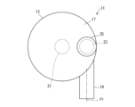
- FIG. 1 is a partially cutaway perspective view showing the overall configuration of a swirl flow control valve according to a first embodiment of the present invention, with a portion cut away so that the inside can be seen.
- FIG. 2 is a plan view of the vortex flow control valve shown in FIG. 1, viewed from above in FIG. 1;
- FIG. 2 is a side view of the vortex flow control valve shown in FIG. 1 when viewed from the side of FIG. 1;
- FIG. 2 is an explanatory diagram schematically showing the flow in the vortex chamber of the vortex flow control valve shown in FIG. 1 when viewed from above in FIG. 1;
- FIG. 2 is an explanatory diagram schematically showing the flow in the vortex chamber of the vortex flow control valve shown in FIG.
- FIG. 2 is an explanatory diagram schematically showing a flow in a state where a protruding portion does not protrude into the vortex chamber of the vortex flow control valve shown in FIG. 1 .
- FIG. 2 is an explanatory diagram schematically showing a flow in a state in which a protruding portion slightly protrudes into the vortex chamber of the vortex flow control valve shown in FIG. 1 .
- FIG. 8 is an explanatory diagram schematically showing a flow in a state in which a protrusion protrudes further into the vortex chamber of the vortex flow control valve shown in FIG. 1 than in FIG. 7;
- FIG. 8 is an explanatory diagram schematically showing a flow in a state in which a protrusion protrudes further into the vortex chamber of the vortex flow control valve shown in FIG. 1 than in FIG. 7;
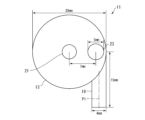
- FIG. 7 is a side view showing a swirl flow control valve according to a second embodiment of the present invention. It is an explanatory diagram for explaining the configuration and dimensions of the swirl flow control valve used in the experiment, and shows the swirl flow control valve from above with the upper end wall (second end wall) removed. ing.
- FIG. 2 is an explanatory diagram for explaining the configuration and dimensions of the swirl flow control valve used in the experiment, and shows the swirl flow control valve viewed from the side.
- FIG. 2 is a piping diagram showing the arrangement of a vortex flow rate control valve, measurement equipment, and adjustment equipment used in an experiment.
- the protrusion was placed at an angular position of 90° and displaced by distances of 3.5 mm, 5.5 mm, and 7.5 mm from the center of the vortex chamber, respectively. It is a line graph plotting the relationship between the protrusion length and the flow rate Q (flow rate from the outlet flow path) when the protrusion length is arranged.
- the protrusions were located at positions deviated from the center of the vortex chamber by distances of 3.5 mm, 5.5 mm, and 7.5 mm at an angular position of 180°. It is a line graph plotting the relationship between the protrusion length and the flow rate Q when the protrusion length is arranged.
- FIG. 14 is an explanatory diagram for explaining the protrusion of the vortex flow control valve used in the numerical simulation using the vortex flow control valve shown in FIG. 13; It shows.
- FIG. 14 is an explanatory diagram for explaining the protrusion of the vortex flow control valve used in the numerical simulation using the vortex flow control valve shown in FIG. 13; It shows.
- FIG. 14 is an explanatory diagram for explaining the protrusion of the vortex flow control valve used in the numerical simulation using the vortex flow control valve shown in FIG. It shows.
- a protrusion with a cross section of shape 1 is placed at an angular position of 90° and offset by a distance of 3.5 mm from the center of the vortex chamber.
- FIG. 3 is a bar graph showing a comparison of the flow rate difference ⁇ Q when the length of the protrusion part is changed from 0.5 mm to 3.5 mm for each shape of the protrusion part under the conditions of .
- a numerical simulation using the swirl type flow control valve shown in Fig. 13 under the condition that the protrusion is located at an angular position of 90° and a distance of 7.5 mm from the center of the swirl chamber, It is a bar graph showing a comparison of the flow rate difference ⁇ Q when the length of the protruding part is changed from 0.5 mm to 3.5 mm for each shape of the part.
- FIG. 13 In a numerical simulation using the vortex flow control valve shown in FIG.
- the protrusions with a cross section of shape 3 are located at angular positions of 90° at distances of 3.5 mm, 5.5 mm, and 7.5 mm from the center of the vortex chamber, respectively.
- 3 is a line graph plotting the relationship between the protruding length and the flow rate Q when the protruding portion is disposed at a position deviated by .
- the position of the inlet flow path relative to the center of the vortex chamber was changed under the condition that the protrusion having a cross section of shape 1 was placed at the center of the vortex chamber.
- a protrusion having a cross section of shape 1 is placed at an angular position of 90° and offset by 7.5 mm from the center of the swirl chamber.
- the flow rate difference ⁇ Q is compared when the length of the protruding portion is changed from 0.5 mm to 3.5 mm at each inlet flow path position. This is a bar graph shown.
- a protrusion having a cross section of shape 1 is placed at an angular position of 90° and offset by 7.5 mm from the center of the swirl chamber.
- the vortex flow rate control valve 11 includes a cylindrical circumferential wall 13 extending along the central axis, and a first end wall 15 and a second end wall 15 and second end walls provided at both ends of the circumferential wall 13 in the direction of the central axis. It includes an end wall 17, an inlet flow path 19, an outlet flow path 21, a protrusion 23, and a drive unit 25 that drives the protrusion 23.
- the first end wall 15 and the second end wall 17 have the same shape and are provided so as to close the end of the circumferential side wall 13 in the central axis direction. 15 and the second end wall 17 constitutes a vortex chamber 27.
- a center axis O of the vortex chamber which extends to connect the center of the first end wall 15 and the center of the second end wall 17 , coincides with the center axis of the circumferential wall 13 .
- the center of the 1st end wall 15 and the center of the 2nd end wall 17 mean the gravity center position of the 1st end wall 15 and the 2nd end wall 17, respectively.
- the first end wall 15 and the second end wall 17 are circular, and the circumferential wall 13 is cylindrical.
- the shapes of the first end wall 15 and the second end wall 17 are not limited to circular shapes, but may be elliptical, triangular, or square if a vortex can be generated in the vortex chamber 27. It can be any shape, such as a polygonal shape.
- the inlet flow path 19 extends along the inlet flow path center axis P1 perpendicular to the vortex chamber center axis O, and is open to the peripheral wall 13.
- the inlet flow path center axis P1 extends through the center of the cross section of the inlet flow path 19.
- the outlet flow path 21 extends from the vortex chamber 27 to the outside along an outlet flow path center axis P2 that is parallel to the vortex chamber center axis O, and is open to the first end wall 15 of the vortex chamber 27. .
- the outlet flow path center axis P2 extends through the center of the cross section of the outlet flow path 21.
- both the inlet channel 19 and the outlet channel 21 are constituted by circular tubes having a circular cross-sectional shape.
- the cross sections of the inlet flow path 19 and the outlet flow path 21 are not limited to circular shapes, but may also be polygonal shapes such as elliptical shapes or square shapes.
- the inlet flow path 19 is configured by a straight circular tube, but it may have another shape such as a nozzle shape as long as the fluid can flow into the vortex chamber 27. .
- the inlet flow path 19 is provided so that the center axis P1 of the inlet flow path passes through an eccentric position away from the center axis O of the vortex chamber. Therefore, the fluid flowing in from the inlet channel 19 hits the circumferential wall 13 in the vortex chamber 27 and flows along the circumferential wall 13 to generate a swirling flow, which turns into a vortex and flows toward the outlet channel 21 from the outlet channel 21. leak.
- the inlet flow path 19 is preferably provided so that the fluid flowing into the vortex chamber 27 from the inlet flow path 19 flows along the circumferential wall 13 in order to easily generate a swirling flow.
- the outlet flow path 21 can be formed at any point in the first end wall 15. It can be provided at any location. That is, the outlet flow path 21 is located at a position where the outlet flow path center axis P2 is distant from the inlet flow path center axis P1 so that the fluid that has flowed into the vortex chamber 27 from the inlet flow path 19 does not directly flow out from the outlet flow path 21. It is sufficient if it is provided so as to extend through the.
- the inlet flow path 19 extends in the tangential direction of the cylindrical circumferential wall 13 and is connected to the circumferential wall 13 such that the inlet flow path center axis P1 is parallel to the tangential line. flows from the inlet channel 19 into the vortex chamber 27 substantially tangentially to the circumferential wall 13 .
- the outlet flow path 21 is opened to the first end wall 15, and the outlet flow path center axis P2 passes through the center of the first end wall 15, that is, the outlet flow path center axis P2 is aligned with the vortex chamber center axis. It is provided so as to extend above O. With this configuration, the fluid flowing in from the inlet channel 19 flows along the circumferential wall 13 in the vortex chamber 27 to generate a swirling flow, and gradually approaches the center while spirally moving toward the outlet channel 21. It's flowing.
- the protruding part 23 is provided on the second end wall 17 so as to protrude into the vortex chamber 27 toward the first end wall 15, and is driven by the drive part 25 to move the center of the vortex chamber within the vortex chamber 27. It is movable along a movement axis extending parallel to the axis O. By moving the protrusion 23 within the vortex chamber 27 by the drive unit 25, the distance (i.e., the gap) between the top of the protrusion 23 extending from the second end wall 17 and the opposing first end wall 15 is reduced. ) can be changed.
- a cylinder mechanism is used as the drive unit 25, which can change the length of the protrusion 23 into the vortex chamber 27.
- the drive unit 25 is not limited to a cylinder mechanism, and moves the protrusion 23 within the vortex chamber 27 to connect the top of the protrusion 23 extending from the second end wall 17 and the first opposing part.
- the distance that is, the gap
- other appropriate mechanisms such as an electric actuator can be used.
- the drive unit can employ various drive methods such as a manual type, an air drive type, and an electric type.
- the protrusion 23 has a columnar shape, and the cross section of the protrusion 23 perpendicular to the movement axis can have any shape.
- the cross section of the protrusion 23 can be, for example, circular, elliptical, polygonal such as square, triangular, or diamond-shaped, or plate-shaped.
- the protrusion 23 has a cylindrical shape with a circular cross section.
- the protruding portion 23 can also have a conical shape or a polygonal pyramid shape, and a step or a groove may be provided on the circumferential side of the columnar or conical shape.
- the protrusion 23 is arranged so that at least a part of the protrusion 23 is connected to the inlet flow path into the vortex chamber 27 so that the swirling flow of the fluid flowing into the vortex chamber 27 from the inlet flow path 19 collides with the protrusion 23 more quickly. It is preferable that they be arranged so as to overlap on an extension of 19. However, since a vortex is generated in the vortex chamber 27 as described above, if the movement axis of the protrusion 23 is not provided so as to extend on the outlet flow path center axis P2, that is, the protrusion 23 is not connected to the outlet flow path 21. If they are not provided at opposing positions, they will collide with the vortex within the vortex chamber 27. Therefore, the position of the protrusion 23 is not particularly limited as long as it is offset from the position facing the outlet flow path 21.
- the inlet flow path 19 is provided so that the inlet flow path center axis P1 passes through an eccentric position away from the vortex chamber center axis O. Therefore, when the protrusion 23 does not protrude into the vortex chamber 27, the fluid flowing in from the inlet channel 19 generates a swirl flow within the vortex chamber 27, as shown in FIG. It heads toward the outlet channel 21 while winding up, and flows out from the outlet channel 21. On the other hand, when the protrusion 23 protrudes into the vortex chamber 27, the fluid that can flow through the gap between the top of the protrusion 23 and the first end wall 15 is limited to the flow shown in FIGS. As shown by line 29, the swirl continues to maintain the vortex.
- the fluid having the protrusion 23 on the streamline flows through the gap between the outer circumferential surface of the protrusion 23 and the circumferential side wall 13, as shown by the streamline 31 in FIGS. 4 and 5.
- the flow curves greatly inward along the circumferential surface of the protruding portion 23, or flows along the inner circumferential surface of the protruding portion 23 as shown by streamlines 33 in FIGS. 4 and 5.
- the flow curves inward significantly and flows through a short cut to the outlet flow path 21.
- the fluid that flows into the vortex chamber 27 from the inlet flow path 19, turns into a vortex flow, heads toward the outlet flow path 21, and flows out from the outlet flow path 21 produces a pressure loss corresponding to the distance traveled.
- the flow to the outlet flow path 21 is reduced.
- the ratio of the fluid flowing through the short cut increases, the pressure loss of the fluid flowing from the inlet channel 19 to the outlet channel 21 decreases as a whole, and the flow rate of the fluid flowing out from the outlet channel 21 increases. That is, as shown in FIG. 8, the protrusion 23 is moved in a direction in which the top of the protrusion 23 approaches the first end wall 15, so that the top of the protrusion 23 and the first end wall 15 are separated.
- the flow rate of fluid exiting the outlet channel 21 can be increased by reducing the gap between the protrusions 23 and the first end wall 15, while spacing the top of the projection 23 from the first end wall 15, as shown in FIG.
- the flow rate of the fluid flowing out from the outlet channel 21 can be reduced.
- the present inventor moved the protrusion 23 within the vortex chamber 27 so as to change the gap between the top of the protrusion 23 and the first end wall 15, thereby making it possible to contact the part that comes into contact with the target fluid. It has been found that the flow rate of the fluid flowing out from the outlet flow path 21 can be adjusted without providing a contact part, and it can function as a flow rate control valve.
- the flow rate adjustment by the protrusion 23 is performed so that the fluid flowing from the inlet channel 19 becomes a vortex in the vortex chamber 27 and flows toward the outlet channel 21, and the protrusion 23 obstructs this vortex.
- the rate at which the protrusion 23 obstructs the vortex flow could be changed by moving the protrusion 23 within the vortex chamber 27. Therefore, the shape of the vortex chamber 27 and the positions of the inlet channel 19 and the outlet channel 21 are not limited as long as a vortex can be generated in the vortex chamber 27, and as long as the protrusion 23 obstructs the vortex.
- the position of the protrusion 23 is not limited.
- the cross-sectional shape of the protrusion 23 is not limited either. That is, in the vortex flow control valve 11 according to the present invention, a wide range of combinations of configurations are possible.
- the protrusion 23 may be moved within the vortex chamber 27 to change the distance between the top of the protrusion 23 and the first end wall 15.
- the diaphragm 17' functions not only as the second end wall but also as a drive for driving the protrusion 23.
- the diaphragm 17' only needs to be able to move the protruding part 23 while supporting the protruding part 23, so only a part of the second end wall 17 is used as the diaphragm 17', and the diaphragm 17' protrudes into the vortex chamber 27.
- the portion 23 may be supported. Note that in FIG.
- the configuration of the vortex flow control valve 11' of the second embodiment is the same as the vortex flow control valve 11' of the first embodiment, except that the protruding part 23 is moved within the vortex chamber 27 by a diaphragm 17' instead of the drive part 25.
- the operation of the swirl flow control valve 11' of the second embodiment is also the same as that of the swirl flow control valve 11 of the first embodiment. The same applies to the point that the flow rate is adjusted by changing the distance (gap) between the projection 15 and the top of the protrusion 23. Therefore, detailed explanation of the configuration and operation will be omitted here.
- the swirl chamber 27 has a cylindrical shape with a diameter of 20 mm and a height of 4 mm, and a diameter of 4 mm and a length of 15 mm.
- a circular tube-shaped inlet flow path 19 is connected to the circumferential wall 13 so as to extend tangentially, and a circular tube-shaped outlet flow path 21 with a diameter of 4 mm and a length of 10 mm extends along the center axis O of the vortex chamber.
- the road center axis P2 is connected to the first end wall 15 such that it passes through the center of the first end wall 15.
- the protrusion 23 has a cylindrical shape with a diameter of 5 mm, and is deviated by 7 mm from the center of the vortex chamber 27 toward the inlet channel 19 in a direction perpendicular to the inlet channel center axis P1 of the inlet channel 19. It is placed in the specified position. Further, as shown in FIG.
- the pressure difference between the upstream pressure PU and the downstream pressure PD of the swirl flow control valve 11 is adjusted by a pressure regulation valve 35 disposed upstream of the swirl flow control valve 11, while changing the length of the protrusion 23 of the swirl flow control valve 11, the flow rate is measured by a flow meter 37 disposed upstream of the swirl flow control valve 11 (specifically, downstream of the pressure control valve 35).
- the upstream pressure PU and the downstream pressure PD were measured by an upstream pressure gauge 39 and a downstream pressure gauge 41 installed upstream and downstream of the swirl flow control valve 11, respectively.
- FIG. 12 is a graph plotting the relationship between the length (mm) of the protrusion 23 and the flow rate Q (L/min) obtained through an experiment.
- the symbol “ ⁇ ” indicates that the differential pressure between the upstream pressure PU and the downstream pressure PD is 0.05 MPa
- the symbol “ ⁇ ” indicates that the differential pressure is 0.1 MPa
- the symbol “ ⁇ ” indicates that the differential pressure is 0.05 MPa.
- the relationship between the length (mm) of the protrusion 23 and the flow rate Q (L/min) in the case of 2 MPa is shown.
- FIG. 12 under any differential pressure conditions, there is a correlation between the length of the protrusion 23 and the flow rate Q, and the longer the protrusion 23 is, the larger the flow rate Q is. Therefore, it was confirmed that by changing the length of the protrusion 23, the flow rate Q can be changed and the flow rate Q can be adjusted and controlled. It was also confirmed that the flow rate Q increased as the differential pressure increased.
- the simulation is performed in such a manner that the vortex chamber 27 has a cylindrical shape with a diameter of 20 mm and a height of 4 mm, and the inlet channel center axis P1 is separated from the center of the vortex chamber 27 by 7.5 mm.
- the inlet channel is shaped like a circular tube with a diameter of 4 mm so that the right end of the inlet channel 19 in the figure passes through the center of the vortex chamber 27 and is located 15 mm away from a line perpendicular to the center axis P1 of the inlet channel.
- a circular tube-shaped outlet passage 21 with a diameter of 4 mm and a length of 10 mm extends along the swirl chamber center axis O, and the outlet passage center axis P 2 is connected to the center of the first end wall 15 . This is done under the condition that it is connected to the first end wall 15 so as to pass through.
- the protrusion 23 is assumed to have a cylindrical shape with a diameter of 4 mm, and its central axis is located at various angular positions (0°, 45°, 90°, 135°, 180°, 270°) of the vortex chamber 27. They are provided at positions offset from the center by various distances (3.5 mm, 5.5 mm, 7.5 mm) toward the peripheral wall 13, and the length is from 0.5 mm to 3.5 mm.
- the amount of change in the flow rate Q (hereinafter referred to as "flow rate difference ⁇ Q”) was determined by changing the flow rate within the range of . As shown in FIG.
- the "angular position" of the protrusion 23 is parallel to the center axis P1 of the inlet flow path and toward the side closer to the inlet flow path 19 passing through the center of the vortex chamber 27.
- the direction of the extending axis is 0°, and it is defined as the angle that the axis extending from the center of the vortex chamber 27 through the center of the protrusion 23 makes with respect to the 0° axis counterclockwise around the center of the vortex chamber 27. .
- FIG. 14 shows the relationship between the angular position (°) of the protrusion 23 and the flow rate difference ⁇ Q (L/min) obtained when the length of the protrusion 23 was changed from 0.5 mm to 3.5 mm in the simulation.
- This is a graph plotting.
- the symbol " ⁇ " indicates that the center axis of the protrusion 23 is placed at a position offset by a distance of 3.5 mm from the center of the vortex chamber 27, and the symbol “ ⁇ ” indicates that the center axis of the protrusion 23 is located at a position eccentric from the center of the vortex chamber 27.
- ⁇ indicates the case where the center axis of the protrusion 23 is placed at a position eccentric by a distance of 7.5 mm from the center of the vortex chamber 27.
- the relationship between the angular position (°) of the protrusion 23 and the flow rate difference ⁇ Q (L/min) is shown.
- the inlet channel 19 is connected to the circumferential wall 13 so as to extend generally tangentially to the circumferential wall 13, and the outlet channel 21 is connected to the first end wall 15 so as to extend from the center of the vortex chamber 27.
- ⁇ Q can be caused.
- 15 and 16 show the protrusions obtained when the protrusions 23 were provided at angular positions of 90° and 180° and the length of the protrusions 23 was varied from 0.5 mm to 3.5 mm in the simulation, respectively.
- 23 is a line graph plotting the relationship between length (mm) and flow rate (L/min).
- the symbol " ⁇ " indicates that the central axis of the protrusion 23 is located at an angular position of 90 degrees and is eccentric by 3.5 mm from the center of the vortex chamber 27, and the symbol " ⁇ " indicates the center of the protrusion 23.
- the symbol “ ⁇ ” means that the central axis of the protrusion 23 is located at an angular position of 90° and located 7 mm from the center of the vortex chamber 27.
- the relationship between the length (mm) of the protrusion 23 and the flow rate (L/min) when the protrusion 23 is placed at a position eccentric by .5 mm is shown.
- FIG. 1 In addition, in FIG. 1
- the symbol “ ⁇ ” indicates that the central axis of the protrusion 23 is located at an angular position of 180 degrees and is eccentric by 3.5 mm from the center of the vortex chamber 27, and the symbol “ ⁇ ” indicates that the protrusion 23 If the central axis of the protrusion 23 is at an angular position of 180° and the center axis of the protrusion 23 is located at a position offset by 5.5 mm from the center of the vortex chamber 27, the symbol “ ⁇ ” indicates that the central axis of the protrusion 23 is at an angular position of 180° and the center of the vortex chamber 27
- the inlet channel 19 is connected to the circumferential wall 13 so as to extend generally tangentially to the circumferential wall 13
- the outlet channel 21 is connected to the first end wall 15 so as to extend from the center of the vortex chamber 27. Under these conditions, it is possible to adjust and control the flow rate Q by changing the length of the protrusion 23, regardless of the position of the protrusion 23.
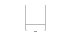
- the cross-sectional shape 1 is a circular shape with a diameter of 4 mm, as shown in FIG. 17A
- the cross-sectional shape 2 is a diamond shape with a diagonal length of 4 mm, as shown in FIG. 17B.
- the cross-sectional shape 3 is a square shape with one side of 4 mm, as shown in FIG. 17C.
- the protrusion 23 was arranged in the direction in which the vortex first hits the corner of the diamond shape, and in the case of cross-sectional shape 3, the protrusion 23 was arranged in the direction in which the vortex was received by the square surface.
- FIG. 18 shows the results obtained when the protrusion 23 is provided so that the central axis is located at an angular position of 90° and offset by 3.5 mm from the center of the vortex chamber 27, and FIG. This is the result obtained when the protrusion 23 is provided so that the central axis is located at an angular position of 90° and offset by 7.5 mm from the center of the vortex chamber 27.
- the inlet channel 19 is connected to the circumferential wall 13 so as to extend generally tangentially to the circumferential wall 13, and the outlet channel 21 is connected to the first end wall 15 so as to extend from the center of the vortex chamber 27. It can be seen that under the condition that the protrusion 23 is connected to the flow rate Q, the flow rate Q can be changed and the flow rate difference ⁇ Q can be generated by changing the length of the protrusion 23, regardless of the cross-sectional shape of the protrusion 23.
- the flow rate difference ⁇ Q depending on the position of the protrusion 23 including the result when the protrusion 23, which is not shown here, is placed at an angular position of 90° and at a position offset by 5.5 mm from the center of the vortex chamber 27. From the comparison, the flow rate difference ⁇ Q is larger for shape 2 (diamond-shaped cross section) than shape 1 (circular cross section), and the flow rate difference ⁇ Q is even larger for shape 3 (square cross section) than shape 2. I found out that it is.
- FIG. 20 shows a protrusion 23 obtained when a protrusion 23 having a cross section of shape 3 is provided at an angular position of 90° and the length of the protrusion 23 is varied from 0.5 mm to 3.5 mm in the simulation. It is a line graph plotting the relationship between the length (mm) and the flow rate Q (L/min).
- the symbol " ⁇ " indicates that the center axis of the protrusion 23 is located at an angular position of 90 degrees and is eccentric by 3.5 mm from the center of the vortex chamber 27, and the symbol “ ⁇ " indicates the center of the protrusion 23.
- the symbol “ ⁇ ” means that the central axis of the protrusion 23 is located at an angular position of 90° and located 7 mm from the center of the vortex chamber 27.
- the relationship between the length (mm) of the protrusion 23 and the flow rate (L/min) when the protrusion 23 is placed at a position eccentric by .5 mm is shown.
- the inlet channel 19 is connected to the circumferential wall 13 so as to extend generally tangentially to the circumferential wall 13, and the outlet channel 21 is connected to the first end wall 15 so as to extend from the center of the vortex chamber 27. Under these conditions, it is possible to adjust and control the flow rate Q by changing the length of the protrusion 23, regardless of the cross-sectional shape of the protrusion 23.
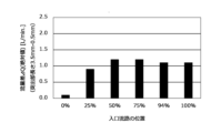
- the position of the inlet channel 19 is determined by the center of the vortex chamber 27 and the inlet flow of the inlet channel 19 relative to the difference between the diameter of the cylindrical vortex chamber 27 and the diameter of the circular tube-shaped inlet channel 19 divided by 2. It was defined as the ratio (%) of the distance to the road center axis P1. This is because the inlet channel 19 can be provided close to the circumferential wall 13 only up to a position where the inlet channel center axis P1 is separated from the circumferential wall 13 by the radius of the inlet channel 19.
- the cylindrical protrusion 23 with a diameter of 4 mm is provided at an angular position of 90°, and the outlet flow path 21 is connected to the first end wall 15 so as to extend from the center of the vortex chamber 27.
- simulations were performed for cases where the position of the inlet flow path 19 with respect to the outlet flow path 21 was 0%, 25%, 50%, 75%, 94%, and 100%.
- FIGS. 21 to 23 show various positions of the protrusion 23 when the position of the inlet channel 19 relative to the outlet channel 21 is changed to 0%, 25%, 50%, 75%, 94%, and 100%.
- ⁇ Q flow rate differences
- FIG. 21 shows the results obtained when the protrusion 23 is provided so that the central axis is located at the center of the vortex chamber 27, and
- FIG. 23 shows the results obtained when the protrusion 23 is provided at a position eccentric by 5.5 mm from the center, and FIG. This is the result obtained when the protrusion 23 was provided so as to be placed at a position eccentric by .5 mm.
- the white bar graphs represent that when the protrusion 23 is short, the flow rate is relatively large, and when the protrusion 23 is long, the flow rate is relatively small.
- the black bar graph represents that when the protrusion 23 is short, the flow rate is relatively small, and when the protrusion 23 is long, the flow rate is relatively large.
- the protrusion 23 is eccentric from the center of the vortex chamber 27. , regardless of the position of the inlet flow path 19, except when the inlet flow path center axis P1 of the inlet flow path 19 passes through the center of the vortex chamber 27 (that is, when the position of the inlet flow path 19 is 0%). First, it can be seen that by changing the length of the protrusion 23, the flow rate Q can be changed and a significant flow rate difference ⁇ Q can be produced.
- the protruding part 23 when the protruding part 23 is provided at the center of the vortex chamber 27 (that is, the protruding part 23 is provided at an angular position of 90 degrees and a distance of 0 mm eccentric from the center of the vortex chamber 27). Regardless of the position of the protrusion 23, the longer the protrusion 23, the lower the flow rate. This means that under the condition that the outlet channel 21 is connected to the first end wall 15 so as to extend from the center of the vortex chamber 27, if the protrusion 23 is provided at the center of the vortex chamber 27, the protrusion 23 is disposed facing the outlet flow path 21, and the longer the protrusion 23 becomes, the more the flow path area for the fluid flowing into the outlet flow path 21 is reduced.
- the protrusion 23 is extended from the center of the vortex chamber 27.
- the inlet channel 19 is located at a position from 50% to 100%.
- the position of the outlet channel 21 was defined by the angular position defined similarly to the angular position of the protrusion 23 and the distance X from the center of the vortex chamber 27, as shown in FIG.
- the position of the outlet flow path 21 indicated by a two-dot chain line in FIG. 13 is expressed as a position at a distance X from an angular position of 0°.
- the inlet flow path 19 was provided such that the inlet flow path center axis P1 was located at a distance of 8 mm from the center of the vortex chamber 27, and the cylindrical protrusion 23 with a diameter of 4 mm was located at an angular position of 90°.
- the vortex chamber 27 was provided at a position offset from the center of the vortex chamber 27 by a distance of 7.5 mm.
- FIGS. 24 and 25 show different angular positions of the outlet flow path 21 when the distance X of the outlet flow path 21 from the center of the vortex chamber 27 is changed to 0 mm, 0.25 mm, 0.5 mm, 1 mm, and 2 mm.
- ⁇ Q flow rate differences
- FIG. 24 shows the results obtained when the outlet flow path 21 is provided at an angular position of 90°
- FIG. 25 shows the results obtained when the outlet flow path 21 is provided at an angular position of 180°. be.
- the inlet flow path 19 is provided such that the inlet flow path center axis P1 is located at a distance of 8 mm from the center of the vortex chamber 27, and the cylindrical protrusion 23 with a diameter of 4 mm is provided.
- the flow rate Q can be adjusted by changing the length of the protrusion 23 regardless of the position of the outlet flow path 21. It can be seen that it is possible to generate a flow rate difference ⁇ Q by changing ⁇ Q. That is, it is possible to adjust the flow rate Q by changing the length of the protrusion 23 without depending on the outlet channel 21.
- FIG. 26 shows the results when the length of the protrusion 23 is changed from 0.5 mm to 3.5 mm when the outlet flow path 21 is provided eccentrically from the center of the vortex chamber 27 at an angular position of 90° in the simulation. It is a line graph plotting the relationship between the obtained length (mm) of the protrusion 23 and the flow rate Q (L/min).
- the symbol “ ⁇ ” indicates that the outlet channel 21 is provided at the center of the vortex chamber 27, and the symbol “ ⁇ ” indicates that the outlet channel 21 is located at an angular position of 90° by 0.25 mm from the center of the vortex chamber 27.
- the symbol " ⁇ " indicates the exit flow when the outlet flow path 21 is installed at an angular position of 90° and an eccentric position of 0.5 mm from the center of the vortex chamber 27. If the channel 21 is provided at an angular position of 90° and offset by 1 mm from the center of the swirl chamber 27, the symbol “*" indicates that the outlet channel 21 is provided at an angular position of 90° and offset by 2 mm from the center of the swirl chamber 27.
- the relationship between the length (mm) of the protrusion 23 and the flow rate (L/min) when the protrusion 23 is provided at a certain position is shown.
- the inlet flow path 19 is provided such that the center axis P1 of the inlet flow path is located at a distance of 8 mm from the center of the vortex chamber 27, and the cylindrical protrusion 23 with a diameter of 4 mm is located at an angular position of 90°.
- the outlet flow path 21 is provided at an eccentric position of 7.5 mm from the center of the vortex chamber 27 and the outlet flow path 21 is provided at an angular position of 90°.
- the present invention is not limited to the illustrated embodiments.
- a cylindrical vortex chamber 27 is employed, but if a vortex can be generated within the vortex chamber 27, an elliptical or polygonal cylindrical vortex chamber may be employed. is also possible.
- the flow rate Q can be changed by changing the gap between the top of the protrusion 23 and the end wall facing it, the protrusion 23 is located not at the second end wall 17 but at the first end. It may be provided on the wall 15.
Landscapes
- Engineering & Computer Science (AREA)
- General Engineering & Computer Science (AREA)
- Mechanical Engineering (AREA)
- Lift Valve (AREA)
Abstract
渦流型流量調節弁(11)は、筒形状の周側壁(13)とその両端に設けられた第1の端壁(15)及び第2の端壁(17)とによって規定される渦室(27)と、入口流路中心軸線(P1)に沿って延び且つ周側壁(13)に開口する入口流路(19)と、出口流路中心軸線(P2)に沿って延び且つ第1の端壁(15)に開口する出口流路(21)と、第1の端壁(15)及び第2の端壁(17)の一方から渦室(27)内に突出する突出部(23)と、渦室(27)内で第1の端壁(15)及び第2の端壁(17)の他方に対して突出部(23)を接近離反させる駆動部(25)とを備える。入口流路(19)は、入口流路中心軸線(P1)が渦室中心軸線(O)から離れた位置を通るように設けられており、突出部(23)の移動により出口流路(21)から流出する流体の流量が調節される。
Description
本発明は、化学工場、半導体製造分野、液晶製造分野、食品分野などの各種産業分野における流体輸送配管に使用される流量調節弁に関する。
各種産業分野における流量の調節の用途では、ニードル弁を使用することが一般的である。例えば特許文献1に記載されているように、ニードル弁は、貫通孔を有する弁座にニードルと呼ばれる弁体のテーパ状の先端部を挿入し、弁座に対してニードルの先端部の周面を接近離反させてニードルと弁座との隙間を変化させることにより、ニードルと弁座との隙間を流通する流体の流量を調節する。流量の微調節を可能にするために、ニードル弁では、ニードルと弁座との隙間が他の流路と比較して狭くなっている。特に、ニードル弁の使用流量範囲の下限付近では、ニードルと弁座との隙間が非常に狭くなる。
上述したように、ニードル弁では、ニードルと弁座との隙間が狭く、特に、ニードル弁の使用流量範囲の下限付近ではニードルと弁座との隙間が非常に狭い。このため、ニードルと弁座との同軸性が悪いと、低流量に調節する際に、本来は接触しないはずのニードルと弁座とが接触して摺動し、ニードル及び弁座の摩耗が生じることがある。このような摩耗が生じると、ニードルと弁座との隙間すなわちニードル弁の開度と流量との関係が変化し、正確な流量への調節が困難になる。また、摩耗により生じたパーティクルが流体中に混入する。このような流体中へのパーティクルの混入は特に半導体製造分野では大きな問題となる。電動アクチュエータを用いてニードルを駆動して、フィードバック制御などにより頻繁に流量の調節を行う場合には、ニードルを常に往復動させることになるため、上述の問題が特に顕著となる。また、ニードル弁の開度と流量との関係が変化すると、フィードバック制御などにおける制御パラメータの再調整が必要になる。このような場合、実質的には寿命として交換されることが多く、維持コストの増加を招く。
弁体と弁座との摺動が生じることを回避する方法としては、例えば特許文献2に開示されているように、旋回流を利用した渦巻型流体素子を利用する方法がある。特許文献2に開示の渦巻型流体素子は、中心部に出力口を有する渦室と、この渦室の外周部に連設し、かつ入力口からの流体を出力口に向け方向規制する入力ノズルと、この入力ノズルから噴出される流体を、その渦室への出口近傍において、渦室内で渦流とする制御流を噴出する制御ノズルとよりなっており、干渉領域において制御ノズルから噴出される制御流を入力ノズルから噴出される噴流に衝突させて偏向させ、渦室内に渦流を生じさせる。渦流を生じさせることにより、干渉領域と出力口との間に圧力差を生じさせて流量抵抗を大きくすることによって、出力流量を制御する。しかしながら、このような渦巻型流体素子では、弁体と弁座との接触は生じないが、流量の制御のためには、制御ノズルから噴出される制御流の流量調整が必要になる。したがって、制御流の流量調整において流量調節弁が必要となってしまい、結局、制御流中へのパーティクルの混入の恐れが残る。
よって、本発明の目的は、従来技術に存する問題を解決して、制御対象となる流体に接する領域内で、弁体と弁座との接触が生じない流量調節弁を提供することにある。
本発明は、上記目的に鑑み、筒形状の周側壁と該周側壁の両端に設けられ互いと対向する第1の端壁及び第2の端壁とによって規定される渦室と、入口流路中心軸線に沿って延び且つ前記周側壁に開口する入口流路と、出口流路中心軸線に沿って延び且つ前記第1の端壁に開口する出口流路とを備え、前記入口流路から流入する流体が前記渦室内で渦流をなして前記出口流路から流出する渦流型流量調節弁であって、前記入口流路は、前記入口流路中心軸線が前記第1の端壁の中心と前記第2の端壁の中心とを結ぶ渦室中心軸線から離れた位置を通るように設けられており、前記渦流型流量調節弁は、前記第1の端壁及び前記第2の端壁の一方から前記渦室内に突出する突出部と、前記渦室内で前記第1の端壁及び前記第2の端壁の他方に対して前記突出部を接近離反させる駆動部とをさらに備え、前記突出部の移動により前記出口流路から流出する流体の流量を調節するようにした渦流型流量調節弁を提供する。
上記渦流型流量調節弁では、筒形状の周側壁とその両端に設けられた互いに対向する第1の端壁及び第2の端壁とによって渦室が規定されており、周側壁に開口する入口流路の入口流路中心軸線が渦室の第1の端壁の中心と第2の端壁の中心とを結ぶ渦室中心軸線から離れた位置を通るように入口流路が設けられ、第1の端壁に出口流路が開口している。したがって、入口流路から流入する流体は、渦室内で旋回流となって渦状に流れた後に、出口流路から流出する。この結果、入口流路から流入して出口流路から流出するまでの旋回流の長さ(すなわち渦流の流線の長さ)に応じて圧力損失が生じる。また、旋回流(渦流)は、渦室内に突出するように第1の端壁及び第2の端壁の一方に設けられた突出部に衝突し、突出部に衝突した旋回流の一部が出口流路へ向かってショートカットして流れる。第1の端壁及び第2の端壁の他方に対して突出部が接近すると、突出部の頂部と第1の端壁及び第2の端壁の他方との隙間が減少して突出部と衝突する旋回流の割合が増えるので、出口流路へ向かってショートカットして流れる旋回流の割合が増加する。反対に、第1の端壁及び第2の端壁の他方に対して突出部が離反すると、突出部の頂部と第1の端壁及び第2の端壁の他方との隙間が増加して突出部と衝突せずに隙間を通過する旋回流の割合が増えるので、出口流路へ向かってショートカットして流れる旋回流の割合が減少する。上述したように、渦室内で入口流路から出口流路まで流れる間に生じる流体の圧力損失は、入口流路から流入して出口流路へ流出するまでの旋回流(渦流)の流線の長さに比例する。したがって、突出部に衝突して出口流路へ向かってショートカットして流れる旋回流の割合が増加すると、入口流路から出口流路への旋回流の流線の長さが全体として減少して、圧力損失が減少し、出口流路から流出する流量が増加する。一方、突出部に衝突して出口流路へ向かってショートカットして流れる旋回流の割合が減少すると、入口流路から出口流路への旋回流の流線の長さが全体として増加して、圧力損失が増加し、出口流路から流出する流量が減少する。このような特性を利用して、駆動部を用いて、第1の端壁及び第2の端壁の一方に設けられた突出部を第1の端壁及び第2の端壁の他方に接近離反させることにより、出口流路から流出する流体の流量を調節することが可能となる。
上記渦流型流量調節弁では、前記突出部が前記渦室中心軸線から偏心した位置に設けられていることが好ましい。渦室内では、渦室の中心が渦流の中心となる。したがって、このように突出部を配置することによって、渦室内の旋回流(渦流)が突出部に衝突しやすくなる。
前記突出部は、少なくとも一部が前記渦室内への前記入口流路の延長上に重なるように、設けられていることがさらに好ましい。入口流路の延長上に重なるように突出部が配置されていれば、入口流路から渦室内に流入する流体が確実に突出部に衝突するので、上述した効果を得やすくなる。
また、前記第1の端壁及び前記第2の端壁が円形状又は楕円形状であることが好ましい。この場合、渦室中心軸線に垂直な渦室の断面すなわち渦室の周側壁も同様に円形状又は楕円形状になるので、流体が周側壁に沿って流れて渦流が円滑に生じやすくなる。
一つの実施形態として、前記出口流路は、前記出口流路中心軸線が前記入口流路中心軸線から離れた位置を通って延びるように設けられているようにしてもよい。
他の実施形態として、前記出口流路は、前記出口流路軸線が前記渦室中心軸線上に延びるように設けられているようにしてもよい。
前記出口流路は、前記出口流路軸線が前記渦室中心軸線から前記入口流路中心軸線へ向かって偏位した位置を通って延びるように設けられているようにしてもよい。
前記突出部が前記出口流路中心軸線から偏位した位置に設けられているようにしてもよい。
前記突出部は、円形断面又は楕円形断面を有しているようにしてもよい。
前記駆動部は、前記突出部を駆動して前記渦室内への前記突出部の突出長さを変化させるようにしてもよい。
また、前記突出部が前記第2の端壁に設けられていてもよい。この場合、前記第1の端壁がダイヤフラムからなり、前記突出部が前記ダイヤフラムに取り付けられ、前記駆動部が前記ダイヤフラムを介して前記突出部を駆動するようにすることができる。
本発明によれば、渦室内に渦流を生じさせ、突出部を設けた一方の端壁と対向する他方の端壁に対して突出部を移動させて突出部と衝突する旋回流の割合を変化させることによって、突出部に衝突して出口流路へ向かってショートカットして流れる旋回流の割合が変化して、入口流路から出口流路への旋回流の流線の長さが全体として増減する。このような特性を利用して、駆動部を用いて、第1の端壁及び第2の端壁の一方に設けられた突出部を第1の端壁及び第2の端壁の他方に接近離反させることにより、出口流路から流出する流体の流量を調節することが可能となり、制御対象流体と接する領域内に弁体及び弁座を設ける必要がなくなり、弁体と弁座との接触部をなくすことが可能となる。したがって、弁体及び弁座の摩耗による流量制御のためのパラメータの再設定が必要となることがなく、流体へのパーティクルの混入も抑制することができる。
以下、図面を参照して、本発明による渦流型流量調節弁の実施の形態を説明する。
最初に、図1から図3を参照して、第1の実施形態の渦流型流量調節弁11の全体構成を説明する。
最初に、図1から図3を参照して、第1の実施形態の渦流型流量調節弁11の全体構成を説明する。
渦流型流量調節弁11は、中心軸線に沿って延びる筒形状の周側壁13と、周側壁13の中心軸線方向の両端に互いに対向するように設けられた第1の端壁15及び第2の端壁17と、入口流路19と、出口流路21と、突出部23と、突出部23を駆動する駆動部25とを備える。第1の端壁15と第2の端壁17とは同じ形状を有し、周側壁13の中心軸線方向の端部を閉塞するように設けられており、周側壁13と第1の端壁15と第2の端壁17とによって取り囲まれた空間が渦室27を構成している。第1の端壁15の中心と第2の端壁17の中心とを結ぶように延びる渦室中心軸線Oは、周側壁13の中心軸線と一致している。なお、本明細書において、第1の端壁15の中心及び第2の端壁17の中心とはそれぞれ第1の端壁15及び第2の端壁17の重心位置を意味する。図示されている実施形態では、第1の端壁15及び第2の端壁17は円形状であり、周側壁13は円筒形状となっている。しかしながら、第1の端壁15及び第2の端壁17の形状は円形状に限定されるものではなく、渦室27内に渦流を生じさせることができれば、楕円形状、三角形状や四角形状のような多角形状など任意の形状とすることができる。
入口流路19は、渦室中心軸線Oと垂直な入口流路中心軸線P1に沿って延び、周側壁13に開口している。入口流路中心軸線P1は入口流路19の断面の中心を通るように延びている。また、出口流路21は、渦室27から外部へ渦室中心軸線Oと平行な出口流路中心軸線P2に沿って延びており、渦室27の第1の端壁15に開口している。出口流路中心軸線P2は出口流路21の断面の中心を通るように延びている。図示されている実施形態では、入口流路19及び出口流路21は共に円形断面形状を有する円管によって構成されている。しかしながら、入口流路19及び出口流路21の断面は、円形状に限定されるものではなく、楕円形状や四角形状のような多角形状とすることも可能である。また、図示されている実施形態では、入口流路19は、ストレート形状の円管によって構成されているが、渦室27内に流体を流入させることができれば、ノズル形状など他の形状としてもよい。
入口流路19は、入口流路中心軸線P1が渦室中心軸線Oから離れた偏心位置を通るように設けられている。したがって、入口流路19から流入した流体は、渦室27内で周側壁13に当たって周側壁13に沿って流れて旋回流を生じ、渦流となって出口流路21へと向かい出口流路21から流出する。入口流路19は、旋回流を生じやすくするために、入口流路19から渦室27内に流入する流体が周側壁13に沿って流れるように設けられることが好ましい。一方、出口流路21は、入口流路19から渦室27内に流入した流体が渦流を生じた後に出口流路21から流出するようになっていれば、第1の端壁15の任意の位置に設けることができる。すなわち、出口流路21は、入口流路19から渦室27内に流入した流体がそのまま出口流路21から流出しないように、出口流路中心軸線P2が入口流路中心軸線P1から離れた位置を通って延びるように設けられていればよい。
図示されている実施形態では、入口流路19は、円筒形状の周側壁13の接線方向に延びて入口流路中心軸線P1が接線と平行となるように周側壁13に接続されており、流体が入口流路19から渦室27内に周側壁13に対して実質的に接線方向に流入するようになっている。また、出口流路21は、第1の端壁15に開口し、出口流路中心軸線P2が第1の端壁15の中心を通るように、すなわち出口流路中心軸線P2が渦室中心軸線O上に延びるように、設けられている。このような構成により、入口流路19から流入した流体が渦室27内で周側壁13に沿って流れて旋回流を生じ、徐々に中心部へ近づきながら渦状に出口流路21へと向かって流れるようになっている。
突出部23は、第1の端壁15に向かって渦室27内に突出するように第2の端壁17に設けられており、駆動部25によって駆動されて渦室27内で渦室中心軸線Oと平行に延びる移動軸線に沿って移動可能になっている。駆動部25によって突出部23を渦室27内で移動させることによって、第2の端壁17から延びる突出部23の頂部とこれと対向する第1の端壁15との間の距離(すなわち隙間)を変えることができる。図示されている実施形態では、駆動部25として、渦室27内への突出部23の突出長さを変化させることができるシリンダ機構が用いられている。しかしながら、駆動部25は、シリンダ機構に限定されるものではなく、渦室27内で突出部23を移動させて第2の端壁17から延びる突出部23の頂部とこれと対向する第1の端壁15との間の距離(すなわち隙間)を変えることができれば、例えば電動アクチュエータなど他の適宜の機構を使用することができる。また、駆動部は、手動式、エア駆動式、電動式など様々な駆動方式を採用することができる。
突出部23は柱形状であり、移動軸線に垂直な突出部23の断面は任意の形状とすることができる。突出部23の断面は、例えば円形状、楕円形状や、四角形状、三角形状、ひし形形状などの多角形状や、板状とすることができる。図示されている実施形態では、突出部23は円形断面を有した円柱形状となっている。また、突出部23は、円錐形状、多角錘形状にすることも可能であり、柱形状や錘形状の周側面に段差や溝が設けられていてもよい。
突出部23は、入口流路19から渦室27内に流入した流体の旋回流がより早く突出部23に衝突するように、少なくとも突出部23の一部が渦室27内への入口流路19の延長上に重なるように配置されることが好ましい。しかしながら、渦室27内では上述したように渦流が生じるので、突出部23の移動軸線が出口流路中心軸線P2上に延びるように設けられていなければ、すなわち突出部23が出口流路21と対向した位置に設けられていなければ、渦室27内において渦流と衝突する。したがって、出口流路21と対向する位置から偏位させた位置であれば特に突出部23の位置は限定されるものではない。
次に、図4から図8を参照して、本発明の渦流型流量調節弁11における作用を説明する。
上述したように、入口流路19は、入口流路中心軸線P1が渦室中心軸線Oから離れた偏心位置を通るように設けられている。したがって、突出部23が渦室27内に突出していない場合には、図6に示されているように、入口流路19から流入した流体は、渦室27内で旋回流を生じて、渦を巻きながら出口流路21へと向かい、出口流路21から流出する。一方、突出部23が渦室27内に突出している場合には、突出部23の頂部と第1の端壁15との隙間を通って流れることができる流体は、図4や図5の流線29に示されているように、そのまま旋回を続けて渦流を維持する。また、流線上に突出部23がある流体は、図4や図5の流線31に示されているように、突出部23の外周面と周側壁13との隙間を通って流れた後に突出部23の周面に沿って内側に大きく曲がって流れたり、図4及び図5の流線33に示されているように、突出部23の内側の外周面に沿って流れて突出部23を回避した後に内側に大きく曲がって流れ、出口流路21へショートカットして流れる。入口流路19から渦室27内に流入して渦流となって出口流路21へ向かい出口流路21から流出する流体は、流れた距離に応じた圧力損失を生じる。したがって、上述したように突出部23により流体がショートカットして流れるようになると、渦室27内で入口流路19から出口流路21までの流線の長さが短くなって圧力損失が減少する。その結果、流量が増加するようになる。
突出部23の頂部を第1の端壁15に接近させる方向に突出部23を移動させて、突出部23の頂部と第1の端壁15との隙間を減少させると、出口流路21へショートカットして流れる流体の比率が増加して、全体として入口流路19から出口流路21まで流れる流体の圧力損失が減少し、出口流路21から流出する流体の流量が増加する。すなわち、図8に示されているように、突出部23の頂部を第1の端壁15に接近させる方向に突出部23を移動させて、突出部23の頂部と第1の端壁15との隙間を減少させることによって、出口流路21から流出する流体の流量を増加させることができる一方、図7に示されているように、突出部23の頂部を第1の端壁15から離間させる方向に突出部23を移動させて、突出部23の頂部と第1の端壁15との隙間を増加させることによって、出口流路21から流出する流体の流量を減少させることができる。本発明者は、このように、突出部23の頂部と第1の端壁15との隙間を変化させるように渦室27内で突出部23を移動させることによって、対象流体と接する部位に当接部を設けることなく、出口流路21から流出する流体の流量を調節し、流量調節弁として機能させ得ることを見出した。
突出部23による流量調節は、上述したように、入口流路19から流入する流体が渦室27内で渦流となって出口流路21へ向かって流れ、突出部23がこの渦流を阻害するよう配置され、渦室27内で突出部23を移動させることによって突出部23が渦流を阻害する割合を変化させることができれば、可能となる。したがって、渦室27内に渦流を生じさせることができる限り、渦室27の形状、入口流路19と出口流路21の位置は限定されるものではなく、突出部23が渦流を阻害する限り、突出部23の位置は限定されるものではない。また、突出部23の断面形状も限定されるものではない。すなわち、本発明による渦流型流量調節弁11では、幅広い構成の組み合わせが可能である。
例えば、図9に示されている第2の実施形態の渦流型流量調節弁11’のように、第2の端壁をダイヤフラム17’によって構成して、突出部23をダイヤフラム17’によって渦室27内に支持し、ダイヤフラム17’を駆動することによって、渦室27内で突出部23を移動させ、突出部23の頂部と第1の端壁15との距離を変化させるようにしてもよい。この場合、ダイヤフラム17’が、第2の端壁としてだけでなく、突出部23を駆動する駆動部としても機能する。ダイヤフラム17’は、突出部23を支持しつつ突出部23を移動させることができればよいので、第2の端壁17の一部のみをダイヤフラム17’とし、ダイヤフラム17’によって渦室27内に突出部23を支持するようにしてもよい。なお、図9において、図1に示されている第1の実施形態と共通する構成要素には、同じ参照符号が付されている。第2の実施形態の渦流型流量調節弁11’の構成は、駆動部25に代えてダイヤフラム17’によって突出部23が渦室27内で移動することを除いて、第1の実施形態の渦流型流量調節弁11と同様であり、第2の実施形態の渦流型流量調節弁11’の作用も第1の実施形態の渦流型流量調節弁11の作用と同様であり、第1の端壁15と突出部23の頂部との距離(隙間)を変化させることで流量の調節が行われる点でも同様である。したがって、ここでは、構成及び作用の詳細な説明は省略する。
以下に、図1に示されている第1の実施形態の渦流型流量調節弁11と同様の構成の渦流型流量調節弁における実験又は数値シミュレーションにより得た、突出部23の長さ、突出部23の位置、突出部23の形状、入口流路19の位置、出口流路21の位置などと、流体の流量又は流量変化量との関係を説明する。以下の説明では、説明を分かりやすくするために、実験又は数値シミュレーションで使用される渦流型流量調節弁の各構成について、渦流型流量調節弁11と同じ参照符号を付する。
最初に、実際に作製した渦流型流量調節弁11を用いた実験によって得られた突出部23の長さと流体の流量Qとの関係を説明する。図10A及び図10Bに示されているように、実験に使用された渦流型流量調節弁11では、渦室27が直径20mm、高さ4mmの円筒形状を有し、直径4mm、長さ15mmの円管形状の入口流路19が接線方向に延びるように周側壁13に接続され、直径4mm、長さ10mmの円管形状の出口流路21が渦室中心軸線Oに沿って延び且つ出口流路中心軸線P2が第1の端壁15の中心を通るように第1の端壁15に接続されている。また、突出部23は、直径5mmの円柱形状を有し、入口流路19の入口流路中心軸線P1と垂直な方向に渦室27の中心から入口流路19へ向かって7mm分だけ偏位させた位置に配置されている。また、図11に示されているように、渦流型流量調節弁11の上流に配置された圧力調整弁35により渦流型流量調節弁11の上流圧力PU及び下流圧力PDの差圧を調整し、渦流型流量調節弁11の突出部23の長さを変えながら、渦流型流量調節弁11の上流(詳細には、圧力調整弁35の下流)に配置された流量計37によって流量を測定すると共に、渦流型流量調節弁11の上流及び下流にそれぞれ設置された上流圧力計39及び下流圧力計41によって上流圧力PU及び下流圧力PDを測定した。
図12は、実験により得られた突出部23の長さ(mm)と流量Q(L/分)との関係をプロットしたグラフである。図12において、記号「●」は上流圧力PUと下流圧力PDの差圧が0.05MPaの場合、記号「▲」は差圧が0.1MPaの場合、記号「■」は差圧が0.2MPaの場合の、突出部23の長さ(mm)と流量Q(L/分)との関係を示す。図12から分かるように、いずれの差圧条件でも、突出部23の長さと流量Qとの間に相関関係が成立しており、突出部23が長くなるほど流量Qが大きくなっている。したがって、突出部23の長さを変えることによって流量Qを変化させ、流量Qを調節、制御することが可能であることが確認された。また、差圧が大きくなるほど、流量Qが大きくなることが確認された。
次に、数値シミュレーション(以下、単にシミュレーションと記載する。)による解析結果を説明する。以下の説明では、シミュレーションは、特に記載が無い限り、渦室27が直径20mm、高さ4mmの円筒形状を有し、入口流路中心軸線P1が渦室27の中心から7.5mmだけ離れた位置を通り且つ入口流路19の図中の右端が渦室27の中心を通り入口流路中心軸線P1と垂直な線から15mmだけ離れて位置するように直径4mmの円管形状の入口流路19が周側壁13に接続され、直径4mm、長さ10mmの円管形状の出口流路21が渦室中心軸線Oに沿って延び且つ出口流路中心軸線P2が第1の端壁15の中心を通るように第1の端壁15に接続されている条件下で行われている。
まず、渦室27における突出部23の位置の影響をシミュレーションにより確認した。ここでは、突出部23は、直径4mmの円柱形状を有するものとし、その中心軸線が様々な角度位置(0°,45°,90°,135°,180°,270°)において渦室27の中心から周側壁13へ向かって様々な距離(3.5mm、5.5mm、7.5mm)だけ偏位させた位置に配置されるように設けられ、その長さを0.5mmから3.5mmの範囲で変化させて流量Qの変化量(以下、「流量差ΔQ」と記載する。)を求めた。なお、突出部23の「角度位置」は、図13に示されているように、入口流路中心軸線P1と平行で且つ渦室27の中心を通って入口流路19に近い側へ向って延びる軸の方向を0°とし、渦室27の中心から突出部23の中心を通るように延びる軸線が渦室27の中心周りに反時計回りに0°の軸に対してなす角度として定義した。
図14は、シミュレーションにおいて突出部23の長さを0.5mmから3.5mmまで変化させたときに得られた突出部23の角度位置(°)と流量差ΔQ(L/分)との関係をプロットしたグラフである。図14において、記号「■」は突出部23の中心軸線が渦室27の中心から距離3.5mmだけ偏心した位置に配置された場合、記号「▲」は突出部23の中心軸線が渦室27の中心から距離5.5mmだけ偏心した位置に配置された場合、記号「●」は突出部23の中心軸線が渦室27の中心から距離7.5mmだけ偏心した位置に配置された場合における突出部23の角度位置(°)と流量差ΔQ(L/分)との関係を示す。
図14から、入口流路19が周側壁13の概略接線方向に延びるように周側壁13に接続され、出口流路21が渦室27の中心から延びるように第1の端壁15に接続されている条件下では、突出部23の角度位置及び突出部23が渦室27の中心から偏心した距離に関わらず、突出部23の長さを変化させることによって、流量Qを変化させて流量差ΔQを生じさせることができることが分かる。また、突出部23が渦室27の中心から離れて設けられているほど、すなわち突出部23が渦室27の周側壁13の近くに設けられているほど、広い範囲での流量調節が可能になり、特に突出部23が90°から180°の範囲の角度位置に設けられているときに、広い範囲での流量調節が可能になることが分かる。これは、流体が入口流路19から渦室27の周側壁13に沿うように流入して渦流となる場合、突出部23が周側壁13の近くで、入口流路19から流入する流体の渦流の始点の近くに配置されるほど、渦流が出口流路21へ向かってショートカットする効果を得やすいためであると推測される。
図15及び図16は、それぞれ、シミュレーションにおいて角度位置90°及び180°に突出部23を設けて突出部23の長さを0.5mmから3.5mmまで変化させたときに得られた突出部23の長さ(mm)と流量(L/分)との関係をプロットした折れ線グラフである。図15において、記号「■」は突出部23の中心軸線が角度位置90°で渦室27の中心から3.5mmだけ偏心した位置に配置された場合、記号「▲」は突出部23の中心軸線が角度位置90°で渦室27の中心から5.5mmだけ偏心した位置に配置された場合、記号「●」は突出部23の中心軸線が角度位置90°で渦室27の中心から7.5mmだけ偏心した位置に配置された場合における突出部23の長さ(mm)と流量(L/分)との関係を示す。また、図16において、記号「■」は突出部23の中心軸線が角度位置180°で渦室27の中心から3.5mmだけ偏心した位置に配置された場合、記号「▲」は突出部23の中心軸線が角度位置180°で渦室27の中心から5.5mmだけ偏心した位置に配置された場合、記号「●」は突出部23の中心軸線が角度位置180°で渦室27の中心から7.5mmだけ偏心した位置に配置された場合における突出部23の長さ(mm)と流量(L/分)との関係を示す。
図15及び図16から、突出部23が角度位置90°と角度位置180°のいずれの位置に設けられている場合でも、突出部23の長さが長くなるほど、また、突出部23が渦室27の中心から離れて設けられているほど、流量Qが大きくなっていることが分かる。特に、突出部23が渦室27の中心から5.5mm以上離れていると、突出部23の長さと流量Qとの相関性が高くなっている。また、ここには示されていないが、突出部23が角度位置0°、45°、135°及び270°の位置にそれぞれ設けられている場合でも、突出部23の長さが長くなるほど、流量Qが大きくなっており、突出部23の長さと流量Qとに相関性があることが確認された。したがって、入口流路19が周側壁13の概略接線方向に延びるように周側壁13に接続され、出口流路21が渦室27の中心から延びるように第1の端壁15に接続されている条件下では、突出部23の位置に関わらず、突出部23の長さを変えることによって流量Qを変化させ、流量Qを調節、制御することが可能である。
次に、突出部23の断面形状の影響をシミュレーションにより確認した。ここでは、図17A~図17Cに示されている三つの断面形状、すなわち断面形状1、断面形状2及び断面形状3をそれぞれ有する突出部23を用いた場合についてシミュレーションを行った。断面形状1は、図17Aに示されているように、直径4mmの円形形状であり、断面形状2は、図17Bに示されているように、対角線の長さが4mmのひし形形状であり、断面形状3は、図17Cに示されているように、一辺が4mmの正方形状である。なお、断面形状2の場合は渦流がひし形形状の角に最初に当たる向きに突出部23を配置し、断面形状3の場合は渦流を正方形の面で受ける向きに突出部23を配置した。
図18及び図19は、それぞれ、突出部23の各断面形状について、突出部23の長さを0.5mmから3.5mmまで変化させたときにシミュレーションで得られた流量差ΔQ(L/分)を比較して示す棒グラフである。図18は、中心軸線が角度位置90°に渦室27の中心から3.5mmだけ偏心した位置に配置されるように突出部23が設けられた場合に得られた結果であり、図19は、中心軸線が角度位置90°に渦室27の中心から7.5mmだけ偏心した位置に配置されるように突出部23が設けられた場合に得られた結果である。
図18及び図19から、入口流路19が周側壁13の概略接線方向に延びるように周側壁13に接続され、出口流路21が渦室27の中心から延びるように第1の端壁15に接続されている条件下では、突出部23の断面形状に関わらず、突出部23の長さを変化させることによって、流量Qを変化させ流量差ΔQを生じさせることができることが分かる。また、ここには示されていない突出部23が角度位置90°に渦室27の中心から5.5mmだけ偏心した位置に配置された場合の結果も含めた突出部23の位置による流量差ΔQの比較から、突出部23が渦室27の中心から離れて設けられているほど、すなわち突出部23が渦室27の周側壁13の近くに設けられているほど、より広い範囲での流量調節が可能になることが分かった。これは、上述したように、流体が入口流路19から渦室27の周側壁13に沿うように流入して渦流となる場合、突出部23が周側壁13の近くで、入口流路19から流入する流体の渦流の始点の近く配置されるほど、渦流が出口流路21へ向かってショートカットさせる効果を得やすいためであると推測される。さらに、ここには示されていない突出部23が角度位置90°に渦室27の中心から5.5mmだけ偏心した位置に配置された場合の結果も含めた突出部23の位置による流量差ΔQの比較から、形状1(円形状断面)よりも形状2(ひし形形状断面)の方が流量差ΔQが大きくなり、形状2よりも形状3(正方形状断面)の方が流量差ΔQがさらに大きくなっていることが分かった。これは、円形状断面の突出部23よりも、角が渦流に最初に当たる向きにひし形形状断面の突出部23を配置した場合や面で渦流を受けるように正方形状断面の突出部23を配置した場合の方が、渦流を出口流路21へ向けてショートカットさせる効果を得やすいためであると推測される。また、渦流が面に当たるようにすれば、長方形状や板状でも、同様に渦流を出口流路21へ向けてショートカットさせ、流量差ΔQを大きくする効果を得ることができると推測される。
図20は、シミュレーションにおいて角度位置90°に形状3の断面を有した突出部23を設けて突出部23の長さを0.5mmから3.5mmまで変化させたときに得られた突出部23の長さ(mm)と流量Q(L/分)との関係をプロットした折れ線グラフである。図20において、記号「■」は突出部23の中心軸線が角度位置90°で渦室27の中心から3.5mmだけ偏心した位置に配置された場合、記号「▲」は突出部23の中心軸線が角度位置90°で渦室27の中心から5.5mmだけ偏心した位置に配置された場合、記号「●」は突出部23の中心軸線が角度位置90°で渦室27の中心から7.5mmだけ偏心した位置に配置された場合における突出部23の長さ(mm)と流量(L/分)との関係を示す。
図20から、突出部23の断面形状が正方形状の場合でも、突出部23の断面形状が円形状である場合と同様に、突出部23の長さが長くなるほど、また、突出部23が渦室27の中心から離れて設けられているほど、流量Qが大きくなっていることが分かる。ここには示されていないが、突出部23の断面形状がひし形形状の場合でも、同様に、突出部23の長さが長くなるほど、また、突出部23が渦室27の中心から離れて設けられているほど、流量Qが大きくなっている。したがって、入口流路19が周側壁13の概略接線方向に延びるように周側壁13に接続され、出口流路21が渦室27の中心から延びるように第1の端壁15に接続されている条件下では、突出部23の断面形状に関わらず、突出部23の長さを変えることによって流量Qを変化させ、流量Qを調節、制御することが可能である。
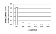
次に、渦室27における入口流路19の位置の影響をシミュレーションにより確認した。入口流路19の位置は、円筒形状の渦室27の直径と円管形状の入口流路19の直径との差を2で割った値に対する渦室27の中心と入口流路19の入口流路中心軸線P1との距離の比率(%)として定義した。これは、入口流路19は、その入口流路中心軸線P1が周側壁13から入口流路19の半径分だけ離れた位置までしか、周側壁13に近づけて設けることができないからである。ここでは、直径4mmの円柱形状の突出部23が角度位置90°に設けられると共に、出口流路21が渦室27の中心から延びるように第1の端壁15に接続されている条件下で、出口流路21に対する入口流路19の位置が0%、25%、50%、75%、94%、100%の場合について、シミュレーションを行った。
図21から図23は、様々な突出部23の位置について、出口流路21に対する入口流路19の位置を0%、25%、50%、75%、94%、100%に変えたときに、突出部23の長さを0.5mmから3.5mmまで変化させて得られた流量差ΔQ(L/分)を比較して示す棒グラフである。図21は、中心軸線が渦室27の中心に配置されるように突出部23が設けられた場合に得られた結果であり、図22は、中心軸線が角度位置90°に渦室27の中心から5.5mmだけ偏心した位置に配置されるように突出部23が設けられた場合に得られた結果であり、図23は、中心軸線が角度位置90°に渦室27の中心から7.5mmだけ偏心した位置に配置されるように突出部23が設けられた場合に得られた結果である。なお、図21から図23において、白抜きの棒グラフは、突出部23が短いときに相対的に流量が多くなり、突出部23が長いときに流量が相対的に少なくなることを表しており、黒塗りの棒グラフは、突出部23が短いときに流量が相対的に少なくなり、突出部23が長いときに流量が相対的に多くなることを表している。
図21から図23を参照すると、出口流路21が渦室27の中心から延びるように第1の端壁15に接続されている条件下では、突出部23が渦室27の中心から偏心した位置にある場合、入口流路19の入口流路中心軸線P1が渦室27の中心を通るとき(すなわち入口流路19の位置が0%のとき)を除き、入口流路19の位置に関わらず、突出部23の長さを変化させることによって、流量Qを変化させ顕著な流量差ΔQを生じさせることができることが分かる。これは、入口流路19の入口流路中心軸線P1が渦室27の中心を通らないと、入口流路19から流入した流体は渦室27内で渦流を生じさせるので、突出部23が渦室27の中心から偏心した位置に設けられていることで、突出部23によって渦の流れの向きを変わらせて出口流路21へショートカットして流れる効果が得られるようになるためであると推測される。したがって、突出部23の長さにより流量Qを調節するためには、入口流路19は入口流路中心軸線P1が渦室27の中心を通らないように設ける必要がある。一方、図21から分かるように、突出部23が渦室27の中心に設けられているとき(すなわち、突出部23が角度位置90°に渦室27の中心から距離0mmだけ偏心した位置に設けられているとき)、突出部23の位置に関わらず、突出部23が長くなるほど、流量が少なくなる。これは、出口流路21が渦室27の中心から延びるように第1の端壁15に接続されている条件下では、突出部23が渦室27の中心に設けられていると、突出部23が出口流路21と対向して配置されることになり、突出部23が長くなるほど出口流路21へ流れ込む流体のための流路面積を減少させることになるからであると推測される。渦室27を渦室中心軸線O方向に見たときに、突出部23が出口流路21と一部でも重なる場合には、同様に、突出部23が長くなるほど、流量が少なくなると推測される。
また、図22と図23とから、出口流路21が渦室27の中心から延びるように第1の端壁15に接続されている条件下では、突出部23が渦室27の中心から7.5mmだけ偏心させた位置に設けられているとき、すなわち突出部23が渦室27の周側壁13にほぼ隣接する位置に設けられているとき、50%から100%の位置に入口流路19を設けることによって、すなわち入口流路中心軸線P1が渦室27の中心側よりも周側壁13側に近くなるように入口流路19を設けることにより、より広い範囲での流量調節が可能になることが分かった。これは、突出部23が渦室27の周側壁13の近くに設けられており且つ入口流路19の入口流路中心軸線P1が渦室27の周側壁13の近くに位置するときは、渦流のショートカット効果がより大きくなるためであると推測される。
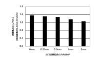
最後に、渦室27における出口流路21の位置の影響をシミュレーションにより確認した。出口流路21の位置は、図13に示されているように、突出部23の角度位置と同様の定義の角度位置と、渦室27の中心からの距離Xとにより定義した。例えば、図13において二点鎖線で示されている出口流路21の位置は、角度位置0°に距離Xの位置と表す。シミュレーションでは、入口流路中心軸線P1が渦室27の中心から距離8mmだけ離れた位置に配置されるように入口流路19が設けられ、直径4mmの円柱形状の突出部23が角度位置90°に渦室27の中心から距離7.5mmだけ偏心した位置に設けられるものとした。
図24及び図25は、異なる出口流路21の角度位置について、渦室27の中心からの出口流路21の距離Xを0mm、0.25mm、0.5mm、1mm、2mmに変えたときに、突出部の長さを0.5mmから3.5mmまで変化させて得られた流量差ΔQ(L/分)を比較して示す棒グラフである。図24は、出口流路21が角度位置90°に設けられた場合に得られた結果であり、図25は、出口流路21が角度位置180°に設けられた場合に得られた結果である。
図24及び図25から、入口流路中心軸線P1が渦室27の中心から距離8mmだけ離れた位置に配置されるように入口流路19が設けられ、直径4mmの円柱形状の突出部23が角度位置90°に渦室27の中心から距離7.5mmだけ偏心した位置に設けられる条件下では、出口流路21の位置に関わらず、突出部23の長さを変化させることによって、流量Qを変化させ流量差ΔQを生じさせることができることが分かる。すなわち、出口流路21によらず、突出部23の長さを変化させることによって流量Qを調節することが可能である。また、ここには示されていない出口流路21が角度位置0°及び角度位置270°に設けられた場合の結果を含めた出口流路21の位置による流量差ΔQの比較から、角度位置90°に渦室27の中心から偏心させ位置に出口流路21が設けられていると、より広い範囲での流量調節が可能になることが分かった。これは、突出部23も角度位置90°に設けられており、突出部23によって曲げられた渦流がより早く出口流路21に到達しやすくなり、渦流を出口流路21へ向けてショートカットさせる効果を得やすくなるためであると推測される。
図26は、シミュレーションにおいて角度位置90°に渦室27の中心から偏心させて出口流路21を設けた場合に、突出部23の長さを0.5mmから3.5mmまで変化させたときに得られた突出部23の長さ(mm)と流量Q(L/分)との関係をプロットした折れ線グラフである。図26において、記号「●」は出口流路21が渦室27の中心に設けられた場合、記号「■」は出口流路21が角度位置90°に渦室27の中心から0.25mmだけ偏心した位置に設けられた場合、記号「◆」は出口流路21が角度位置90°に渦室27の中心から0.5mmだけ偏心した位置に設けられた場合、記号「▲」は出口流路21が角度位置90°に渦室27の中心から1mmだけ偏心した位置に設けられた場合、記号「*」は出口流路21が角度位置90°に渦室27の中心から2mmだけ偏心した位置に設けられた場合における突出部23の長さ(mm)と流量(L/分)との関係を示す。
図26から、渦室27の中心から出口流路21までの距離に関わらず、突出部23の長さが長くなるほど、流量Qが大きくなっていることが分かる。したがって、入口流路中心軸線P1が渦室27の中心から距離8mmだけ離れた位置に配置されるように入口流路19が設けられ、直径4mmの円柱形状の突出部23が角度位置90°に渦室27の中心から距離7.5mmだけ偏心した位置に設けられ、出口流路21が角度位置90°に設けられる条件下では、渦室27の中心からの出口流路21の位置に関わらず、突出部23の長さを変えることによって流量Qを調節、制御することが可能である。また、図26から、出口流路21が渦室27の中心から離れて設けられているほど、流量Qが大きくなっていることが分かる。したがって、より大きな流量を得るためには、渦室27の中心からできるだけ遠くに出口流路21を設けることが好ましい。
以上、図示されている実施形態を参照して、本発明による渦流型流量調節弁を説明したが、本発明は図示されている実施形態に限定されるものではない。例えば、図示されている実施形態では、円筒形状の渦室27が採用されているが、渦室27内に渦流を生じさせることができれば、楕円や多角形の筒状の渦室を採用することも可能である。また、突出部23の頂部とこれと対向する端壁との隙間を変化させることによって流量Qを変化させることができるので、突出部23は、第2の端壁17ではなく、第1の端壁15に設けられてもよい。
11 渦流型流量調節弁
13 周側壁
15 第1の端壁
17 第2の端壁
17’ ダイヤフラム
19 入口流路
21 出口流路
23 突出部
25 駆動部
27 渦室
13 周側壁
15 第1の端壁
17 第2の端壁
17’ ダイヤフラム
19 入口流路
21 出口流路
23 突出部
25 駆動部
27 渦室
Claims (12)
- 筒形状の周側壁と該周側壁の両端に設けられ互いと対向する第1の端壁及び第2の端壁とによって規定される渦室と、入口流路中心軸線に沿って延び且つ前記周側壁に開口する入口流路と、出口流路中心軸線に沿って延び且つ前記第1の端壁に開口する出口流路とを備え、前記入口流路から流入する流体が前記渦室内で渦流をなして前記出口流路から流出する渦流型流量調節弁であって、
前記入口流路は、前記入口流路中心軸線が前記第1の端壁の中心と前記第2の端壁の中心とを結ぶ渦室中心軸線から離れた位置を通るように設けられており、前記渦流型流量調節弁は、前記第1の端壁及び前記第2の端壁の一方から前記渦室内に突出する突出部と、前記渦室内で前記第1の端壁及び前記第2の端壁の他方に対して前記突出部を接近離反させる駆動部とをさらに備え、前記突出部の移動により前記出口流路から流出する流体の流量を調節することを特徴とする渦流型流量調節弁。 - 前記突出部が前記渦室中心軸線から偏心した位置に設けられている、請求項1に記載の渦流型流量調節弁。
- 前記突出部は、少なくとも一部が前記渦室内への前記入口流路の延長上に重なるように、設けられている、請求項2に記載の渦流型流量調節弁。
- 前記第1の端壁及び前記第2の端壁が円形状又は楕円形状である、請求項1に記載の渦流型流量調節弁。
- 前記出口流路は、前記出口流路中心軸線が前記入口流路中心軸線から離れた位置を通って延びるように設けられている、請求項1から請求項4の何れか一項に記載の渦流型流量調節弁。
- 前記出口流路は、前記出口流路軸線が前記渦室中心軸線上に延びるように設けられている、請求項5に記載の渦流型流量調節弁。
- 前記出口流路は、前記出口流路軸線が前記渦室中心軸線から前記入口流路中心軸線へ向かって偏位した位置を通って延びるように設けられている、請求項5に記載の渦流型流量調節弁。
- 前記突出部が前記出口流路中心軸線から偏位した位置に設けられている、請求項5に記載の渦流型流量調節弁。
- 前記突出部は、円形断面又は楕円形断面を有している、請求項5に記載の渦流型流量調節弁。
- 前記駆動部は、前記突出部を駆動して前記渦室内への前記突出部の突出長さを変化させる、請求項5に記載の渦流型流量調節弁。
- 前記突出部が前記第2の端壁に設けられている、請求項5に記載の渦流型流量調節弁。
- 前記第2の端壁がダイヤフラムからなり、前記突出部が前記ダイヤフラムに取り付けられ、前記駆動部が前記ダイヤフラムを介して前記突出部を駆動する、請求項11に記載の渦流型流量調節弁。
Applications Claiming Priority (2)
| Application Number | Priority Date | Filing Date | Title |
|---|---|---|---|
| JP2022-084137 | 2022-05-23 | ||
| JP2022084137 | 2022-05-23 |
Publications (1)
| Publication Number | Publication Date |
|---|---|
| WO2023228915A1 true WO2023228915A1 (ja) | 2023-11-30 |
Family
ID=88919274
Family Applications (1)
| Application Number | Title | Priority Date | Filing Date |
|---|---|---|---|
| PCT/JP2023/019009 WO2023228915A1 (ja) | 2022-05-23 | 2023-05-22 | 渦流型流量調節弁 |
Country Status (1)
| Country | Link |
|---|---|
| WO (1) | WO2023228915A1 (ja) |
Citations (3)
| Publication number | Priority date | Publication date | Assignee | Title |
|---|---|---|---|---|
| JP2003020959A (ja) * | 2001-07-09 | 2003-01-24 | Ishikawajima Harima Heavy Ind Co Ltd | 緊急減速機能付き燃料流量制御装置 |
| JP2004136085A (ja) * | 2002-09-27 | 2004-05-13 | Toto Ltd | マッサージノズル及びマッサージシステム |
| JP2005535445A (ja) * | 2002-08-15 | 2005-11-24 | エンジニアリング ヴォーテックス ソリューションズ プロプライエタリー リミテッド | 噴射ノズルを通過する流動体の流れを制御する器具 |
-
2023
- 2023-05-22 WO PCT/JP2023/019009 patent/WO2023228915A1/ja unknown
Patent Citations (3)
| Publication number | Priority date | Publication date | Assignee | Title |
|---|---|---|---|---|
| JP2003020959A (ja) * | 2001-07-09 | 2003-01-24 | Ishikawajima Harima Heavy Ind Co Ltd | 緊急減速機能付き燃料流量制御装置 |
| JP2005535445A (ja) * | 2002-08-15 | 2005-11-24 | エンジニアリング ヴォーテックス ソリューションズ プロプライエタリー リミテッド | 噴射ノズルを通過する流動体の流れを制御する器具 |
| JP2004136085A (ja) * | 2002-09-27 | 2004-05-13 | Toto Ltd | マッサージノズル及びマッサージシステム |
Similar Documents
| Publication | Publication Date | Title |
|---|---|---|
| JP4979197B2 (ja) | 高リカバリ音速ガス弁 | |
| US10427501B2 (en) | Outlet device | |
| US20240003465A1 (en) | Fluid flow control devices and systems, and methods of flowing fluids therethrough | |
| KR102208101B1 (ko) | 유체 제어 장치 | |
| AU2005210939B2 (en) | Expansion valve of refrigerating apparatus | |
| WO2023228915A1 (ja) | 渦流型流量調節弁 | |
| JP5986093B2 (ja) | 一体形成型ブースト低減機能を有する弁箱 | |
| WO2023228916A1 (ja) | 渦流型流量調節弁 | |
| US8556226B2 (en) | Valve with the device enhancing capability of its closure member and related seat ring to resist erosion | |
| TW202409457A (zh) | 渦流型流量調節閥 | |
| JP2009250122A (ja) | 燃料噴射弁 | |
| EP0503462B1 (en) | Fluidic vibrating type flowmeter | |
| RU2514328C1 (ru) | Дроссельно-регулирующее устройство | |
| US20230048962A1 (en) | Fluid flow control devices and systems, and methods of flowing fluids | |
| CN112049972B (zh) | 用于控制过程流体流动的提升阀 | |
| JP7457194B1 (ja) | 渦流式流体混合器 | |
| WO2016135823A1 (ja) | 流体制御弁 | |
| JP6901123B2 (ja) | ドラフトコック | |
| JP2015052389A (ja) | 流体制御弁 | |
| JP7457193B1 (ja) | 渦流式流体混合器 | |
| WO2019215990A1 (ja) | 旋回流調整装置 | |
| WO2022091313A1 (ja) | 流体制御装置 | |
| CN101978198B (zh) | 阀门 | |
| JP6312320B2 (ja) | 主蒸気弁、及び蒸気タービン | |
| US20190368905A1 (en) | Magnetic-inductive flowmeter and measuring tube |
Legal Events
| Date | Code | Title | Description |
|---|---|---|---|
| 121 | Ep: the epo has been informed by wipo that ep was designated in this application |
Ref document number: 23811787 Country of ref document: EP Kind code of ref document: A1 |