WO2023228422A1 - ファスナーストリンガー及びその製造方法 - Google Patents
ファスナーストリンガー及びその製造方法 Download PDFInfo
- Publication number
- WO2023228422A1 WO2023228422A1 PCT/JP2022/021799 JP2022021799W WO2023228422A1 WO 2023228422 A1 WO2023228422 A1 WO 2023228422A1 JP 2022021799 W JP2022021799 W JP 2022021799W WO 2023228422 A1 WO2023228422 A1 WO 2023228422A1
- Authority
- WO
- WIPO (PCT)
- Prior art keywords
- fastener
- tape
- cover material
- sheet
- fastener stringer
- Prior art date
- Legal status (The legal status is an assumption and is not a legal conclusion. Google has not performed a legal analysis and makes no representation as to the accuracy of the status listed.)
- Ceased
Links
Images




Classifications
-
- A—HUMAN NECESSITIES
- A44—HABERDASHERY; JEWELLERY
- A44B—BUTTONS, PINS, BUCKLES, SLIDE FASTENERS, OR THE LIKE
- A44B19/00—Slide fasteners
- A44B19/24—Details
- A44B19/32—Means for making slide fasteners gas or watertight
-
- A—HUMAN NECESSITIES
- A44—HABERDASHERY; JEWELLERY
- A44B—BUTTONS, PINS, BUCKLES, SLIDE FASTENERS, OR THE LIKE
- A44B19/00—Slide fasteners
- A44B19/24—Details
- A44B19/26—Sliders
- A44B19/265—Sliders with means for preventing the accidental intrusion of material into the slider body, e.g. with shield or guard
-
- A—HUMAN NECESSITIES
- A44—HABERDASHERY; JEWELLERY
- A44B—BUTTONS, PINS, BUCKLES, SLIDE FASTENERS, OR THE LIKE
- A44B19/00—Slide fasteners
- A44B19/24—Details
- A44B19/34—Stringer tapes; Flaps secured to stringers for covering the interlocking members
-
- B—PERFORMING OPERATIONS; TRANSPORTING
- B29—WORKING OF PLASTICS; WORKING OF SUBSTANCES IN A PLASTIC STATE IN GENERAL
- B29C—SHAPING OR JOINING OF PLASTICS; SHAPING OF MATERIAL IN A PLASTIC STATE, NOT OTHERWISE PROVIDED FOR; AFTER-TREATMENT OF THE SHAPED PRODUCTS, e.g. REPAIRING
- B29C48/00—Extrusion moulding, i.e. expressing the moulding material through a die or nozzle which imparts the desired form; Apparatus therefor
- B29C48/001—Combinations of extrusion moulding with other shaping operations
- B29C48/0021—Combinations of extrusion moulding with other shaping operations combined with joining, lining or laminating
-
- B—PERFORMING OPERATIONS; TRANSPORTING
- B29—WORKING OF PLASTICS; WORKING OF SUBSTANCES IN A PLASTIC STATE IN GENERAL
- B29C—SHAPING OR JOINING OF PLASTICS; SHAPING OF MATERIAL IN A PLASTIC STATE, NOT OTHERWISE PROVIDED FOR; AFTER-TREATMENT OF THE SHAPED PRODUCTS, e.g. REPAIRING
- B29C48/00—Extrusion moulding, i.e. expressing the moulding material through a die or nozzle which imparts the desired form; Apparatus therefor
- B29C48/03—Extrusion moulding, i.e. expressing the moulding material through a die or nozzle which imparts the desired form; Apparatus therefor characterised by the shape of the extruded material at extrusion
- B29C48/07—Flat, e.g. panels
- B29C48/08—Flat, e.g. panels flexible, e.g. films
-
- B—PERFORMING OPERATIONS; TRANSPORTING
- B29—WORKING OF PLASTICS; WORKING OF SUBSTANCES IN A PLASTIC STATE IN GENERAL
- B29L—INDEXING SCHEME ASSOCIATED WITH SUBCLASS B29C, RELATING TO PARTICULAR ARTICLES
- B29L2005/00—Elements of slide fasteners
Definitions
- the present disclosure relates to a fastener stringer and a method for manufacturing the same.
- Inexpensive slide fasteners that are water repellent and expensive slide fasteners that are highly watertight or airtight are known.
- a zipper tape with a polyurethane film bonded thereto is known.
- the opposing ends of left and right fastener tapes are butted against each other when the left and right injection molded elements are engaged.
- Patent Document 1 discloses that a fastener element is sewn to a tape portion on which a covering layer of an elastic material such as synthetic resin or rubber is attached to a base fabric, and a thin-walled portion is formed in the covering layer at this sewing location. (See FIG. 1 of Patent Document 1).
- Patent Document 2 discloses sewing a coiled monofilament onto a watertight/airtight strip (see FIG. 1 of Patent Document 2).
- Patent Document 3 discloses that a film (see numerals 21 and 22 in FIG. 1 of Patent Document 3) is attached to a fastener tape (see numerals 11 and 12 in FIG. 1 of Patent Document 3), and as shown in FIG. 1 of the same document. It is disclosed that the films are brought into contact with each other in this manner.
- FIG. 15 of Patent Document 4 discloses forming a seal portion (see reference numeral 13 in FIG. 15 of Patent Document 4) in a waterproof seal layer (see reference numeral 4 in FIG. 15 of Patent Document 4).
- FIG. 4 of Patent Document 5 discloses that the bent edge (see reference numeral 7 in FIG. 4 of Patent Document 5) is made to protrude beyond the engagement center line (see reference numeral 8 of FIG. 4 of Patent Document 5). ing.
- Patent Document 6 discloses that in a slide fastener in which a support tape is covered with a coating layer made of synthetic rubber or the like, when the fastener elements are engaged, the contact areas of the opposing edges of each coating layer are as shown in FIG. 1 of the same document. It is disclosed that it is formed as shown. Slide fasteners similar to those in Patent Document 6 are also disclosed in Patent Documents 7 and 8.
- slide fasteners that are inexpensive enough to be water repellent and expensive slide fasteners that can ensure high watertightness or airtightness, but slide fasteners that are in between these are not available on the market. It has not been.
- the inventors of the present application have found a new problem: to provide a slide fastener with a new structure that is easy to mass-produce at low cost and has more sufficient watertightness or airtightness.
- a fastener stringer includes a fastener tape, a fastener element provided on a side edge of the fastener tape, and a cover material that is formed of a soft material and covers the fastener tape, and has a thickness of the fastener tape.
- the fastener tape includes a cover material having a seal portion at a location opposite the fastener element in the direction of the fastener tape.
- the cover material includes a flexible core sheet extending in the longitudinal direction of the fastener stringer, and the core sheet is embedded in the soft material in such a manner that one side thereof is at least partially exposed or both sides thereof are not exposed. .
- the covering material is configured as a support substrate that supports the fastener tape.
- one end of the core sheet in the width direction of the fastener stringer is embedded in the seal portion.
- One end of the core material sheet in the width direction of the fastener stringer is positioned away from the sealing surface of the sealing part within the upper range of the fastener element, and a soft material is located between the one end of the core material sheet and the sealing surface in the width direction of the cover material.
- a section may be formed. The distance between one end of the core sheet and the sealing surface in the width direction of the cover material may be 1 cm or less.
- the core sheet is a woven sheet, a knitted sheet, a mixed woven and knitted sheet, a paper sheet, a nonwoven fabric, or a metal foil.
- the seal portion is displaceable away from and toward the fastener tape.
- the covering material is wider than the fastener tape.
- the cover material may have a mounting portion located further away from the sealing portion than the fastener tape in the width direction of the fastener stringer and having an exposed surface not covered by the fastener tape.
- the seal portion is shaped to include an oblique ramp or a vertical wall.
- the fastener element is a coiled element sewn to the fastener tape by an attachment thread.
- the fastener tape has a major surface that is at least partially covered by a covering material, and the attachment thread seam can be covered by the covering material on the major surface.
- a method for manufacturing a fastener stringer includes a cover material in which a flexible core sheet is embedded in a soft material in such a manner that one side thereof is at least partially exposed or both sides thereof are not exposed.
- the method includes a step of forming by extrusion molding, and a step of bonding a cover material to a fastener tape having side edges provided with fastener elements and supporting the fastener tape with the cover material.
- the cover material is laminated to the fastener tape such that the cover material has a seal at a location opposite the fastener element with respect to the fastener tape.
- the covering material is affixed to the fastener tape in such a manner that the seal portion is movable away from and toward the fastener tape.
- the extrusion of the covering material from the extruder and the application of the covering material to the fastener tape occur continuously without cutting the covering material between the extruder and the location of the application. It will be done.
- a fastener stringer with a new structure that is easy to mass-produce at low cost and has more sufficient watertightness or airtightness.
- FIG. 2 is a top view of a slide fastener according to one aspect of the present disclosure. It is a partial bottom view of a slide fastener.
- FIG. 3 is a partially enlarged view showing the fastener elements in an engaged state.
- FIG. 2 is a schematic partial cross-sectional view of the slide fastener, showing a state in which the left and right fastener elements are engaged and the left and right seal portions are butted against each other.
- FIG. 2 is a schematic partial cross-sectional view of the slide fastener, mainly showing the mounting portion on the outside in the width direction.
- FIG. 2 is a schematic partial cross-sectional view of the slide fastener, showing how the seal portion of the cover material is deformed within the slider.
- FIG. 1 is a schematic flowchart illustrating a process for manufacturing a fastener stringer according to one aspect of the present disclosure.
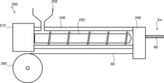
- 1 is a schematic diagram of a non-limiting example extruder;
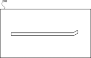
- FIG. FIG. 2 is a front view of a non-limiting example cap.
- It is a schematic diagram regarding the manufacturing method of a fastener stringer.
- It is a schematic diagram regarding the manufacturing method of a fastener stringer.
- It is a schematic diagram regarding the manufacturing method of a slide fastener.
- It is a schematic partial cross-sectional view of another example of a slide fastener.
- It is a schematic diagram showing variations of the cover material.
- It is a schematic diagram showing variations of the cover material.
- It is a schematic diagram showing variations of the cover material.
- It is a schematic diagram showing variations of the cover material.
- It is a schematic diagram showing variations of the cover material.
- It is a schematic diagram showing variations of the cover material.
- It is
- the moving direction of the slider 8 that opens and closes the slide fastener 1 is the front-rear direction (see double-headed arrow FB in FIG. 1).
- a direction that is equal to the width direction of the slide fastener 1 and perpendicular to the front-rear direction is the left-right direction (see double-headed arrow LR in FIG. 1).
- a direction that is equal to the thickness direction of the slide fastener 1 and perpendicular to the front-rear direction is defined as an up-down direction. Note that the up-down direction is orthogonal to both the front-back direction and the left-right direction.
- the vertical direction does not necessarily mean the vertical direction (direction of gravity).
- the vertical direction regarding the slide fastener 1 is included in the horizontal direction (perpendicular to the vertical direction).
- the directions referred to herein are independent of the vertical direction.
- the slide fastener 1 is a flexible long part that extends in the front-rear direction with a constant left-right width, and engages and disengages the left and right pair of fastener stringers 2m and 2n. It has a slider 8 for As the slider 8 moves forward, the left and right fastener stringers 2m and 2n engage with each other, and a liquid-tight seal is formed by abutting the seal portions 56, which will be described later. As the slider 8 moves backward, the left and right fastener stringers 2m and 2n are disengaged, and the butt between the seal portions 56, which will be described later, is also eliminated (as a result, the liquid-tight seal disappears).
- the fastener stringers 2m and 2n are flexible long parts that extend in the front and back direction with a constant left and right width, and include water permeable stringers 7m and 7n and cover materials 5m and 5n bonded thereto. .
- the water-permeable stringers 7m, 7n and the cover materials 5m, 5n are also flexible long parts that extend in the front-rear direction with a constant left-right width.
- the water-permeable stringers 7m, 7n include water-permeable fastener tapes 3m, 3n, and fastener elements 4m, 4n provided on the side edges 33 of the fastener tapes 3m, 3n.
- the fastener tapes 3m and 3n are flexible long parts that extend long in the front and back direction with a constant left and right width.
- the fastener tapes 3m and 3n have water permeability and allow penetration and permeation of liquid (for example, water), and are, for example, woven fabrics, knitted fabrics, or woven/knitted fabrics. Specifically, the structure of the fastener tape and its constituent yarns (for example, weft and warp yarns) absorb liquid, resulting in liquid penetration and permeation.
- the fastener tapes 3m and 3n include a large number of warp yarns and at least one weft yarn.
- spots with a sparse yarn density are formed between warp yarns adjacent in the weft direction, and spots with a sparse yarn density are also formed between weft portions adjacent in the warp direction, which can contribute to liquid penetration. Even in the form of a knitted fabric, spots with a sparse thread density are formed between the mesh yarns, which can contribute to liquid penetration.
- the fastener elements 4m, 4n are coil-shaped elements sewn to the fastener tapes 3m, 3n by an attachment thread 44, and are typically arranged on one main surface of the fastener tapes 3m, 3n. sewn on its side edges.
- any sewing method such as single chain stitch or double chain stitch can be employed.
- the coiled element is constructed from a helically wound monofilament with gaps between the monofilament sections and is therefore water permeable.
- the coiled element is formed by an element unit U1 that is equivalent to one turn of a helically wound monofilament and is continuously formed in the front-rear direction (see FIG. 3).
- the element unit U1 includes a head 41 extending in the vertical direction, a pair of legs 42 each connected to the upper and lower ends of the head 41, and a connecting portion 43 connecting the legs 42 between adjacent element units U1.
- the head 41 is formed to be appropriately wider than the leg 42 in the front-rear direction, so that the heads 41 of the left and right fastener elements 4m and 4n can be engaged with and disengaged from each other.
- Other types of fastener elements can also be employed.
- a core string may be introduced into the hollow part of the spiral monofilament of the coiled element, but this can be omitted.
- the cover materials 5m and 5n are wider than the fastener tapes 3m and 3n, and may be separable into an inner portion 53, an attachment portion 54, and an intermediate portion 55 in the width direction. .
- the intermediate portion 55 continues from the inner portion 53, and the attachment portion 54 continues from the intermediate portion 55.
- Each inner side portion 53 of the left and right cover members 5m, 5n includes a seal portion 56 that abuts against each other when the left and right fastener elements 4m, 4n are engaged.
- the inner part 53 may be partially bonded to one main surface of the fastener tapes 3m and 3n.
- the entire intermediate portion 55 may be bonded to one main surface of the fastener tapes 3m and 3n. As shown in FIG.
- the boundary between the inner part 53 and the intermediate part 55 of the cover materials 5m, 5n can be defined on a plane P1 that is in contact with the connecting part 43 of the fastener elements 4m, 4n and perpendicular to the width direction of the slide fastener 1.
- the boundary between the intermediate portion 55 of the cover materials 5m, 5n and the attachment portion 54 can be defined on a plane P2 that is in contact with the outer end surface 39 of the fastener tapes 3m, 3n and perpendicular to the width direction of the slide fastener 1.
- the mounting portions 54 of the cover materials 5m, 5n are not bonded to the fastener tapes 3m, 3n, and therefore have exposed surfaces 95 that are not covered by the fastener tapes 3m, 3n.
- the attachment portion 54 is located further away from the seal portion 56 than the fastener tapes 3m, 3n in the width direction of the fastener stringers 2m, 2n.
- One or both sides of the attachment part 54 can be used to attach the fastener stringers 2m, 2n (for example, by a method such as thermocompression bonding) to an opening of a target article such as clothing, a bag, or a tent.
- the slide fastener 1 can have a central plane CP in a state in which the fastener elements 4m and 4n are engaged.
- the center plane CP is a plane perpendicular to the width direction of the slide fastener 1.
- the center plane CP is set at the center of each head 41 engaged with the fastener elements 4m and 4n in the width direction of the slide fastener 1.
- Each of the planes P1 and P2 described above is one plane parallel to the central plane CP.
- the cover materials 5m and 5n cover (directly) the fastener tapes 3m and 3n in order to prevent liquid penetration and permeation through the fastener tapes 3m and 3n (in other words, they are laminated directly on top of the fastener tapes 3m and 3n). and has a sealing portion 56 at a position opposite to (for example, above) the fastener elements 4m, 4n with respect to the fastener tapes 3m, 3n in the thickness direction of the fastener tapes 3m, 3n (see FIG. 4).
- the seal portion 56 is provided above the fastener tapes 3m, 3n.
- the seal portion is covered with a fastener element in plan view. In other words, the seal portion is in contact with the connecting portion 43 of the fastener elements 4m, 4n, as shown in FIG. .
- Each of the cover materials 5m and 5n is formed from a soft material 99, and in particular, from a soft material 99 that does not allow penetration or permeation of liquid (e.g., rubber, elastomer, resin (e.g., polyurethane), or a mixture thereof). be done. Thanks to the waterproofness of the cover materials 5m and 5n, the waterproofness of the zipper stringers 2m and 2n is ensured regardless of the water permeability of the water permeable stringers 7m and 7n (that is, the zipper stringers 2m and 2n function as waterproof stringers). However, the slide fastener 1 functions as a waterproof fastener).
- the soft material 99 can include one or more additives to enhance or improve its physical or chemical properties.
- the soft material 99 can also contain pigments (inorganic pigments, organic pigments) in addition to the above-mentioned main materials, so that the cover material is colored in a desired color according to the pigment.
- the waterproof performance (waterproof level) of the slide fastener 1 depends on various internal parameters such as the material, thickness, and density of the components of the fastener stringers 2m and 2n, and also depends on external parameters such as the water pressure applied to the slide fastener 1. It also depends on the target parameters.
- the slide fastener 1 can be designed to have a waterproof performance between an inexpensive slide fastener that has water repellency as described at the beginning and an expensive slide fastener that can ensure high watertightness or airtightness.
- the waterproof level may be lower or higher than this.
- the cover materials 5m and 5n are configured as support base materials that support the fastener tapes 3m and 3n (see FIGS. 4 and 5). That is, the cover materials 5m and 5n are not supported by the fastener tapes 3m and 3n, but the fastener tapes 3m and 3n are supported by the cover materials 5m and 5n.
- the covering material 5m, 5n has a lower flexibility than the fastener tape 3m, 3n.
- the cover materials 5m and 5n may be formed thicker than the fastener tapes 3m and 3n.
- the cover materials 5m and 5n may be formed to have a predetermined thickness or more in order to have desired sealing performance.
- the cover materials 5m, 5n include a flexible core sheet 60 extending in the longitudinal direction of the fastener stringers 2m, 2n. Furthermore, the core sheet 60 is embedded in the soft material 99 in such a manner that one side thereof is at least partially exposed or both sides thereof are not exposed. According to this configuration, the soft material 99 is supported by the core sheet 60, and the shape of the cover materials 5m and 5n including the seal portion 56 is stabilized. As a non-limiting effect, it is possible to use inexpensive fastener tapes 3m and 3n that can be mass-produced, and it is possible to promote cost reduction of the slide fastener 1.
- the core sheet 60 extends in the longitudinal direction of the slide fastener 1 (also the fastener stringers 2m, 2n) in order to support the fastener tapes 3m, 3n.
- a layered soft material 99 is attached to and supported on one or both sides of the core sheet 60 (see FIG. 4). When one side of the core sheet 60 is exposed, the other side of the core sheet 60 opposite to this exposed side is not exposed.
- the core sheet 60 is exposed on the opposite side from the soft material 99.
- the core sheet 60 is covered with the soft material 99 on both sides and is not exposed. Note that whether or not the surface of the core material sheet 60 is exposed is based on whether or not the cover materials 5m and 5n can be visually recognized from the outside.
- the soft material 99 has a two-dimensional extent and can be observed as a layer or sheet in the cross section of the cover materials 5m and 5n in both the width direction and the longitudinal direction of the slide fastener 1.
- the fastener tapes 3m and 3n may be a type of fastener tape in which a fastener element is not woven (for example, a fastener tape in which a coil element is sewn).
- the cover materials 5m and 5n serve as supporting base materials instead of the fastener tapes 3m and 3n. Therefore, the use of inexpensively mass-produced fastener tapes (water-permeable stringers 7m and 7n) is allowed, and cost reduction of the slide fastener 1 is promoted. It can be said that the high flexibility of the inexpensive fastener tapes 3m and 3n is offset or compensated for by the low flexibility of the cover materials 5m and 5n.
- the fastener element in which a fastener element (simply referred to as a coil element in which a monofilament is spirally wound) is woven into the fastener tape, the fastener element is incorporated into the tape structure by engagement with the weft of the fastener tape. .
- the flexibility of the fastener tape is reduced and it can be used as a support substrate for soft materials such as polyurethane coatings, but it tends to be expensive.
- the fastener tapes 3m and 3n have a tape upper surface 31 and a tape lower surface 32, and have a thickness defined by these (see FIG. 4).
- the tape upper surface 31 and the tape lower surface 32 are main surfaces that define the thickness of the fastener tapes 3m and 3n.
- the thickness direction of the fastener tapes 3m and 3n is a direction perpendicular to the tape upper surface 31 and the tape lower surface 32.
- the fastener elements 4m, 4n are sewn to the tape lower surfaces 32 of the fastener tapes 3m, 3n.
- the cover materials 5m and 5n have an upper surface 51 and a lower surface 52, and have a thickness defined by these.
- the cover materials 5m and 5n are bonded to the tape upper surfaces 31 of the fastener tapes 3m and 3n, typically via an adhesive or an adhesive layer. A strong force is required to peel the cover materials 5m, 5n from the fastener tapes 3m, 3n, and if you try to forcefully peel them off, one or both may be destroyed.
- the seams of the attachment threads 44 are covered by the covering material 5m, 5n on the tape upper surface 31 of the fastener tapes 3m, 3n, and accordingly the seams of the fastener elements 4m, 4n are covered on the tape lower surface 32 side of the fastener tapes 3m, 3n. The position is stabilized. As a result, the abutment between the seal portions 56 when the fastener elements 4m and 4n are engaged is strengthened, and the waterproofness of the slide fastener 1 is enhanced.
- the fastener tapes 3m, 3n In the width direction of the slide fastener 1 (also the fastener stringers 2m, 2n), the fastener tapes 3m, 3n have an inner end surface 38 (see FIG. 4) and an outer end surface 39 (see FIG. 5).
- the inner end surfaces 38 of the left and right fastener tapes 3m, 3n are arranged to face each other, and a gap 9 is formed between them.
- a liquid-tight seal is formed by abutting the seal portions 56 against each other at a position covering the gap 9 in plan view (in short, at a position above the gap 9), and if this is not formed, the liquid permeates through the gap 9. and transmission is prevented.
- the cover materials 5m, 5n have a sealing surface 58 (see FIG. 4) as an inner end surface and an outer end surface 59 (see FIG. 5).
- the core sheet 60 has an inner end 68 (see FIG. 4) and an outer end 69 (see FIG. 5).
- the sealing surface 58 of the cover material 5m is located further outward of the fastener tape 3m than the inner end surface 38 of the fastener tape 3m.
- the sealing surface 58 of the cover material 5n is located further outward of the fastener tape 3n than the inner end surface 38 of the fastener tape 3n.
- the outer end surface 59 of the cover material 5m is located further outward of the fastener tape 3m than the outer end surface 39 of the fastener tape 3m.
- the outer end surface 59 of the cover material 5n is located further outward of the fastener tape 3n than the outer end surface 39 of the fastener tape 3n. This makes it easier to weld the slide fastener 1 to the fabric of the other party.
- the tape outward means a direction extending from a position on the main surface of a certain fastener tape to a position outside the main surface, intersecting the side edges extending in the longitudinal direction of the fastener tape.
- the inner end may be referred to as one end and the outer end may be referred to as the other end.
- the inner end surface can also be called one end surface, and the outer end surface can also be called the other end surface.
- the inner end 68 of the core sheet 60 is embedded in the seal portion 56, increasing the hardness of the seal portion 56 and enhancing its sealing performance.
- the inner end 68 of the core sheet 60 is positioned away from the seal surface 58 of the seal portion 56 within the range above the fastener elements 4m, 4n (width W4 of the fastener elements 4m, 4n), and A soft portion 57 is formed between the inner end 68 of the sheet 60 and the sealing surface 58, so that the sealing portion 56 can have appropriate softness.
- the force required to move the slider 8 to engage the fastener elements 4m, 4n and bring the seal portions 56 into abutment can be reduced.
- the core sheet 60 is a woven fabric, a knitted fabric, or paper, fibers may be mixed into the soft material 99 (for example, its layered portion, seal portion 56, and/or soft portion 57).
- the distance S57 between the inner end 68 of the core sheet 60 and the sealing surface 58 in the width direction of the slide fastener 1 is equal to the width W4 of the fastener elements 4m and 4n in the same direction (see FIG. 4) may be 1/2 or less or 1/3 or less. This promotes the above-mentioned effects.
- the distance between the inner end 68 of the core sheet 60 and the sealing surface 58 in the width direction of the slide fastener 1 (also the cover materials 5m, 5n) is within 1 cm, within 5 mm, within 3 mm, or within 2 mm.
- a woven fabric sheet, a knitted fabric sheet, a woven/knitted mixed sheet, a paper sheet, a nonwoven fabric, or a metal foil can be used as the core material sheet 60.
- a woven sheet, a knitted sheet, a mixed woven and knitted sheet, a paper sheet, a nonwoven fabric, or a metal foil all have flexibility.
- the woven sheet, knitted sheet, mixed woven sheet, paper sheet, non-woven fabric or metal foil is also advantageously wider than the fastener tapes 3m, 3n included in the water-permeable stringers 7m, 7n. This makes it possible to support the soft material 99 to a sufficient extent or extent.
- the cover materials 5m and 5n can have a pattern corresponding to the weave and/or knitted structure of the core material sheet 60.
- the slide fastener 1 can have an appearance similar to a traditional slide fastener.
- the covering materials 5m and 5n have a pattern in which inclined lines are continuously arranged in the longitudinal direction.
- a fastener tape having the same structure as the fastener tapes 3m and 3n included in the water-permeable stringers 7m and 7n can be used, and material cost reduction can be promoted.
- the seal portion 56 may be movable in the vertical direction away from and toward the tape upper surface 31 of the fastener tapes 3m and 3n (see FIG. 4). Specifically, the inner part 53 is not partially bonded to the side edge part 33 of the fastener tapes 3m, 3n on the opposite side of the fastener elements 4m, 4n, and as a result, the inner part 53 is not bonded to the side edge part 33 of the fastener tapes 3m, 3n on the opposite side of the fastener elements 4m, 4n. A displaceable seal portion 56 is formed, which helps reduce the force required to move the slider 8.
- each seal portion 56 moves upwardly away from the fastener elements 4m, 4n from the position shown by the dotted line in FIG. 4 to the position shown by the solid line. can be displaced.
- the seal portion 56 can be formed into various shapes.
- the seal portion 56 may be configured as or include an obliquely sloped portion as shown in FIG.
- the seal portion 56 gradually separates upward from the tape upper surface 31 of the fastener tapes 3m, 3n as the tape extends outward.
- the portion of the core sheet 60 included in the seal portion 56 gradually separates upward from the tape upper surface 31 of the fastener tapes 3m, 3n as the tape extends outward.
- the left and right seal portions 56 may come into at least partial contact with the fastener tapes 3m and 3n, respectively (see FIG. 6).
- the slider 8 is designed for engaging and disengaging the fastener stringers 2m and 2n.
- the slider 8 has an upper wing plate 81, a lower wing plate 82, and a connecting column (not shown) that extends up and down to connect these, thereby forming a Y-shape.
- An element passageway is defined.
- Flange walls 83 that stand upward are provided on the left and right side edges of the lower wing plate 82 to restrict movement of the left and right fastener elements 4m and 4n in the width direction of the slider 8.
- the fastener stringers 2m and 2n can be manufactured by the procedure shown in FIG.
- a waterproof chain is manufactured by engaging the fastener stringers 2m and 2n.
- a slide fastener is manufactured by engaging a slider with an engaged fastener element of a waterproof chain.
- Existing technology and equipment in the field of slide fasteners can be used to cut the waterproof chain and install the slider, and detailed explanations will be omitted.
- the manufacturing method of the fastener stringers 2m, 2n includes a step (S1) of forming cover materials 5m, 5n by extrusion molding, and a fastener tape in which fastener elements 4m, 4n are provided on the side edge 33.
- the process may include a step (S2) of bonding cover materials 5m, 5n to 3m, 3n and supporting the fastener tapes 3m, 3n by the cover materials 5m, 5n.
- the method for manufacturing the fastener stringers 2m, 2n can further include the step of manufacturing water permeable stringers 7m, 7n in which the fastener elements 4m, 4n are provided on the side edges 33 of the fastener tapes 3m, 3n.
- the fastener elements 4m, 4n may be coiled elements sewn to the fastener tapes 3m, 3n by attachment threads 44.
- an extrusion molding machine 200 illustrated in FIG. 8 can be used, and the above-mentioned cover materials 5m and 5n can be manufactured continuously at low cost by operating the extrusion molding machine 200.
- the extrusion molding machine 200 includes a rotating machine 210, a screw 220 rotated by the rotating machine 210, a cylinder 230 housing the screw 220, a mouthpiece 240, a soft material input port 250, and a reel 260 around which a core sheet 60 is wound. has.
- the screw 220 rotates, the soft material is sent toward the mouthpiece 240, passes through the opening of the mouthpiece 240, and is discharged with a cross section corresponding to the shape of the opening.
- the core material sheet 60 is also sent to the cap 240 in synchronization with the soft material.
- the core sheet 60 functions as a support base material that supports the soft material, and suppresses the flow of the soft material when passing through the opening of the mouthpiece 240.
- the shape of the extruded product (fastener stringers 2m, 2n) extruded from the extrusion molding machine 200 is stabilized.
- the extrusion molding machine 200 may have various configurations other than those shown.
- the extrusion molded product i.e., the cover material 5m, 5n including the seal portion 56
- the core sheet 60 is introduced into the soft material during extrusion molding, the soft material is attached to one or both sides of the core sheet 60 and supported, and the extrusion molded product (i.e., the cover including the seal portion 56 The shapes of the materials 5m and 5n are stabilized.
- the core sheet 60 is embedded in the soft material in such a manner that one side thereof is at least partially exposed or both sides thereof are not exposed.
- the cover materials 5m and 5n having a desired cross-sectional shape can be formed from the soft material and the core sheet.
- the opening shape of the cap 240 is designed to define the outline of the cross-sectional shape perpendicular to the longitudinal direction of the cover members 5m and 5n.
- the base 240 shown in FIG. 9 is used to manufacture the cover materials 5m and 5n shown in FIG. 4. Bases with other opening shapes can also be used.
- the core sheet 60 is set to run at a predetermined position in the opening of the cap 240. In some cases, the core sheet is inserted so that one end (the inner end 68 described above) of the core sheet 60 in the lateral direction perpendicular to the extrusion direction of the extruded product (fastener stringers 2m, 2n) is embedded in the seal portion 56. 60 driving routes are set. One end of the core sheet 60 (the above-mentioned inner end 68) is positioned away from the sealing surface 58 of the sealing portion 56, and a soft portion is located between the one end of the core material sheet 60 (the above-mentioned inner end 68) and the sealing surface 58.
- the running path of the core sheet 60 can also be set so that the core sheet 57 is formed, and the same effect as described above can be obtained.
- the cover materials 5m, 5n may be bonded to the fastener tapes 3m, 3n so as to have the seal portions 56 at positions opposite to the fastener elements 4m, 4n.
- the cover materials 5m, 5n can be bonded to the fastener tapes 3m, 3n in such a manner that the seal portion 56 can be displaced away from and toward the fastener tapes 3m, 3n.
- the adhesive or adhesive layer used to bond the cover materials 5m, 5n and the fastener tapes 3m, 3n is preferably made of a water-resistant adhesive material. It is also possible to thermocompress the cover materials 5m, 5n and the fastener tapes 3m, 3n without using an adhesive material.
- step S1 and step S2 are performed continuously during the same period.
- step S1 and step S2 can also be performed discontinuously in different periods.
- cover materials 5m and 5n continuously extruded from the extrusion molding machine 200 are cut, wound onto a reel, etc., and stored. On different days and/or at different locations, the cover materials 5m and 5n previously produced and stored as described above are attached to the fastener tapes 3m and 3n.
- an adhesive is applied to at least one of the lower surface of the cover material 5m and the upper surface of the fastener tape 3m, or an adhesive layer is laminated thereon.
- the cover material 5m and the fastener tape 3m are laminated with an adhesive or an adhesive layer interposed therebetween, so that they are stuck together.
- the seal portion of the cover material can be appropriately positioned with respect to the fastener element.
- FIG. 12 it is also possible to individually bond the cover materials 5m and 5n to the fastener tapes 3m and 3n of the fastener chain in which the left and right water-permeable stringers are engaged.
- bonding the cover material to the fastener tape of the fastener chain entails and implies bonding the cover material to the fastener tape of the water-permeable stringer.
- the water permeable stringers 7m and 7n to which the cover materials 5m and 5n are bonded.
- the fastener tapes 3m, 3n have a folded part 302 which is folded back with respect to a tape main part 301, and fastener elements 4m, 4n are sewn to this folded part 302. Even if the water-permeable stringers 7m and 7n of different configurations are adopted in this way, the same effects as described above can be obtained as long as the above-mentioned characteristics are provided.
- the shapes of the cover materials 5m and 5n can also be changed in various ways.
- the seal portion 56 When forming the seal portion 56 as an inclined portion, the seal portion 56 may be formed into a tapered shape in the cross section in the longitudinal direction of the fastener stringers 2m, 2n, as shown in FIG. This narrows the vertical width of the sealing surface 58 of the sealing part 56, reducing the force required to move the slider 8 to engage the fastener elements 4m and 4n and bring the sealing parts 56 into a butt state. can be done.
- the inner end 68 of the core sheet 60 is embedded in the seal portion 56.
- the seal portion 56 may be shaped as or include a wall portion that stands vertically in the longitudinal cross section of the fastener stringers 2m, 2n.
- the wall portion extends in the longitudinal direction of the fastener stringers 2m, 2n, and has a pair of wall surfaces that define the width of the wall portion, one of which functions as a sealing surface 58.
- the height of the wall is adjustable.
- the cover materials 5m and 5n can also be formed as flat sheet materials. Even in such a case, the cover members 5m and 5n can have the seal portion 56 by bonding them in an appropriate positional relationship to the water-permeable stringers 7m and 7n.
- cover materials 5m and 5n can also be manufactured by a method other than extrusion molding.
- the symbols included in the claims are for reference only and should not be referred to for the purpose of limiting the scope of the claims.
Landscapes
- Engineering & Computer Science (AREA)
- Mechanical Engineering (AREA)
- Slide Fasteners (AREA)
Priority Applications (6)
| Application Number | Priority Date | Filing Date | Title |
|---|---|---|---|
| CN202280093835.9A CN119053265A (zh) | 2022-05-27 | 2022-05-27 | 拉链牙链带及其制造方法 |
| US18/865,626 US20250318607A1 (en) | 2022-05-27 | 2022-05-27 | Fastener stringer and method of producing the same |
| JP2024522882A JPWO2023228422A1 (https=) | 2022-05-27 | 2022-05-27 | |
| PCT/JP2022/021799 WO2023228422A1 (ja) | 2022-05-27 | 2022-05-27 | ファスナーストリンガー及びその製造方法 |
| DE112022007290.3T DE112022007290T5 (de) | 2022-05-27 | 2022-05-27 | Befestigungsstreifen und verfahren zu dessen herstellung |
| TW111137468A TWI844125B (zh) | 2022-05-27 | 2022-10-03 | 拉鏈牙鏈帶及其製造方法 |
Applications Claiming Priority (1)
| Application Number | Priority Date | Filing Date | Title |
|---|---|---|---|
| PCT/JP2022/021799 WO2023228422A1 (ja) | 2022-05-27 | 2022-05-27 | ファスナーストリンガー及びその製造方法 |
Publications (1)
| Publication Number | Publication Date |
|---|---|
| WO2023228422A1 true WO2023228422A1 (ja) | 2023-11-30 |
Family
ID=88918801
Family Applications (1)
| Application Number | Title | Priority Date | Filing Date |
|---|---|---|---|
| PCT/JP2022/021799 Ceased WO2023228422A1 (ja) | 2022-05-27 | 2022-05-27 | ファスナーストリンガー及びその製造方法 |
Country Status (6)
| Country | Link |
|---|---|
| US (1) | US20250318607A1 (https=) |
| JP (1) | JPWO2023228422A1 (https=) |
| CN (1) | CN119053265A (https=) |
| DE (1) | DE112022007290T5 (https=) |
| TW (1) | TWI844125B (https=) |
| WO (1) | WO2023228422A1 (https=) |
Citations (3)
| Publication number | Priority date | Publication date | Assignee | Title |
|---|---|---|---|---|
| JPS55485U (https=) * | 1979-04-06 | 1980-01-05 | ||
| JPS59111705A (ja) * | 1982-12-15 | 1984-06-28 | ワイケイケイ株式会社 | 水密・気密性スライドファスナー連続ストリンガーと、その生産方法、生産用具 |
| CN212650520U (zh) * | 2020-06-28 | 2021-03-05 | 福建艾思艾拉链有限公司 | 一种新型防泼水拉链 |
Family Cites Families (14)
| Publication number | Priority date | Publication date | Assignee | Title |
|---|---|---|---|---|
| JPS4915548A (https=) * | 1972-06-05 | 1974-02-12 | ||
| JPS60246704A (ja) | 1984-05-19 | 1985-12-06 | ワイケイケイ株式会社 | 気密、防水性を有するスライドフアスナ−の製造方法 |
| JPH0510190Y2 (https=) | 1986-07-10 | 1993-03-12 | ||
| JPS6341561U (https=) | 1987-07-28 | 1988-03-18 | ||
| JPH0410711A (ja) | 1990-04-27 | 1992-01-14 | Nec Corp | 半導体論理回路 |
| JPH0410711U (https=) * | 1990-05-18 | 1992-01-29 | ||
| US5386616A (en) * | 1993-04-08 | 1995-02-07 | W. L. Gore & Associates, Inc. | Water resistant closure and method for applying same |
| DE19924539C2 (de) | 1999-05-28 | 2001-05-10 | Dynat Ges Fuer Verschlustechni | Fluiddichter Reißverschluß |
| JP4030688B2 (ja) * | 1999-08-18 | 2008-01-09 | 株式会社クラレ | 基布 |
| DE10030185B4 (de) | 2000-06-20 | 2005-06-09 | Dynat Verschlußtechnik GmbH | Fluiddichter Reißverschluß |
| JP4064251B2 (ja) * | 2003-01-28 | 2008-03-19 | Ykk株式会社 | スライドファスナー用テープ |
| GB0912179D0 (en) * | 2009-07-13 | 2009-08-26 | Ykk Europ Ltd | Watertight zip fastener |
| CN104168793B (zh) * | 2012-03-14 | 2017-05-24 | Ykk株式会社 | 防水性拉链及防水制品 |
| TWI791908B (zh) * | 2019-10-09 | 2023-02-11 | 周朝木 | 防滲拉鏈及其製法 |
-
2022
- 2022-05-27 US US18/865,626 patent/US20250318607A1/en active Pending
- 2022-05-27 WO PCT/JP2022/021799 patent/WO2023228422A1/ja not_active Ceased
- 2022-05-27 JP JP2024522882A patent/JPWO2023228422A1/ja active Pending
- 2022-05-27 DE DE112022007290.3T patent/DE112022007290T5/de active Pending
- 2022-05-27 CN CN202280093835.9A patent/CN119053265A/zh active Pending
- 2022-10-03 TW TW111137468A patent/TWI844125B/zh active
Patent Citations (3)
| Publication number | Priority date | Publication date | Assignee | Title |
|---|---|---|---|---|
| JPS55485U (https=) * | 1979-04-06 | 1980-01-05 | ||
| JPS59111705A (ja) * | 1982-12-15 | 1984-06-28 | ワイケイケイ株式会社 | 水密・気密性スライドファスナー連続ストリンガーと、その生産方法、生産用具 |
| CN212650520U (zh) * | 2020-06-28 | 2021-03-05 | 福建艾思艾拉链有限公司 | 一种新型防泼水拉链 |
Also Published As
| Publication number | Publication date |
|---|---|
| DE112022007290T5 (de) | 2025-03-20 |
| US20250318607A1 (en) | 2025-10-16 |
| TWI844125B (zh) | 2024-06-01 |
| CN119053265A (zh) | 2024-11-29 |
| JPWO2023228422A1 (https=) | 2023-11-30 |
| TW202345721A (zh) | 2023-12-01 |
Similar Documents
| Publication | Publication Date | Title |
|---|---|---|
| JP5387912B2 (ja) | ジップファスナー及びジップファスナーの製造方法 | |
| KR100385526B1 (ko) | 방수성 슬라이드 파스너와 그 제조 방법 | |
| KR850001049B1 (ko) | 방수 슬라이드 파스너 스트링어 및 그의 제조방법 | |
| US9237783B2 (en) | Slide fastener | |
| CN103501651B (zh) | 拉链及其制造方法 | |
| US8910583B2 (en) | Method of sewing fastener stringer and method of manufacturing product to which fastener is attached | |
| US8756768B2 (en) | Waterproof slide fastener | |
| US20160095405A1 (en) | Thick Pad-Integrated Double-Layer Nylon Zipper or Single-Layer Nylon Reverse Zipper and Luggage Mounting Arrangement | |
| TW201500018A (zh) | 具防滲結構之夾式扣合元件拉鏈 | |
| US9622551B2 (en) | Method of manufacturing portion of slide fastener | |
| CN104955354A (zh) | 带拉链的物品以及带拉链的物品的制造方法 | |
| WO2023228422A1 (ja) | ファスナーストリンガー及びその製造方法 | |
| US20060207069A1 (en) | Water resistant slide fastener | |
| CN221330431U (zh) | 拉链 | |
| US12232580B2 (en) | Slide fastener and method of producing waterproof chain | |
| ES2357134T3 (es) | Cierre deslizante estanco a los fluídos. | |
| US20260033602A1 (en) | Slide fastener with sealing function | |
| US20250234968A1 (en) | Coil-type fluid-impervious zipper and commercial product using same | |
| WO2023167292A1 (ja) | 複合ストリンガー及びその製造方法、並びに複合ストリンガーのテープ部の製造方法 | |
| WO2023166685A1 (ja) | レールファスナー及びその製造方法 |
Legal Events
| Date | Code | Title | Description |
|---|---|---|---|
| 121 | Ep: the epo has been informed by wipo that ep was designated in this application |
Ref document number: 22943822 Country of ref document: EP Kind code of ref document: A1 |
|
| WWE | Wipo information: entry into national phase |
Ref document number: 2024522882 Country of ref document: JP |
|
| WWE | Wipo information: entry into national phase |
Ref document number: 202280093835.9 Country of ref document: CN |
|
| WWE | Wipo information: entry into national phase |
Ref document number: 18865626 Country of ref document: US |
|
| WWE | Wipo information: entry into national phase |
Ref document number: 112022007290 Country of ref document: DE |
|
| WWP | Wipo information: published in national office |
Ref document number: 112022007290 Country of ref document: DE |
|
| 122 | Ep: pct application non-entry in european phase |
Ref document number: 22943822 Country of ref document: EP Kind code of ref document: A1 |
|
| WWP | Wipo information: published in national office |
Ref document number: 18865626 Country of ref document: US |