WO2023228422A1 - Fastener stringers and production method therefor - Google Patents
Fastener stringers and production method therefor Download PDFInfo
- Publication number
- WO2023228422A1 WO2023228422A1 PCT/JP2022/021799 JP2022021799W WO2023228422A1 WO 2023228422 A1 WO2023228422 A1 WO 2023228422A1 JP 2022021799 W JP2022021799 W JP 2022021799W WO 2023228422 A1 WO2023228422 A1 WO 2023228422A1
- Authority
- WO
- WIPO (PCT)
- Prior art keywords
- fastener
- tape
- cover material
- sheet
- fastener stringer
- Prior art date
Links
- 238000004519 manufacturing process Methods 0.000 title claims description 18
- 239000000463 material Substances 0.000 claims abstract description 125
- 239000007779 soft material Substances 0.000 claims abstract description 36
- 239000011162 core material Substances 0.000 claims description 57
- 238000007789 sealing Methods 0.000 claims description 30
- 238000001125 extrusion Methods 0.000 claims description 22
- 238000000034 method Methods 0.000 claims description 17
- 239000004744 fabric Substances 0.000 claims description 11
- 239000002759 woven fabric Substances 0.000 claims description 6
- 239000011888 foil Substances 0.000 claims description 5
- 239000002184 metal Substances 0.000 claims description 5
- 239000004745 nonwoven fabric Substances 0.000 claims description 5
- 238000005520 cutting process Methods 0.000 claims description 3
- 238000003475 lamination Methods 0.000 claims 1
- XLYOFNOQVPJJNP-UHFFFAOYSA-N water Substances O XLYOFNOQVPJJNP-UHFFFAOYSA-N 0.000 description 15
- 238000010586 diagram Methods 0.000 description 9
- 239000007788 liquid Substances 0.000 description 8
- 239000000853 adhesive Substances 0.000 description 7
- 230000001070 adhesive effect Effects 0.000 description 7
- 230000035515 penetration Effects 0.000 description 6
- 239000012790 adhesive layer Substances 0.000 description 4
- 239000013256 coordination polymer Substances 0.000 description 4
- 229920001971 elastomer Polymers 0.000 description 4
- 239000010410 layer Substances 0.000 description 4
- 230000000670 limiting effect Effects 0.000 description 4
- 230000008569 process Effects 0.000 description 4
- 230000000694 effects Effects 0.000 description 3
- 230000009467 reduction Effects 0.000 description 3
- 238000009958 sewing Methods 0.000 description 3
- 239000011247 coating layer Substances 0.000 description 2
- 239000000806 elastomer Substances 0.000 description 2
- 235000012438 extruded product Nutrition 0.000 description 2
- 230000035699 permeability Effects 0.000 description 2
- 239000000049 pigment Substances 0.000 description 2
- 229920002635 polyurethane Polymers 0.000 description 2
- 239000004814 polyurethane Substances 0.000 description 2
- 239000000047 product Substances 0.000 description 2
- 230000002940 repellent Effects 0.000 description 2
- 239000005871 repellent Substances 0.000 description 2
- 229920005989 resin Polymers 0.000 description 2
- 239000011347 resin Substances 0.000 description 2
- 239000005060 rubber Substances 0.000 description 2
- 239000000758 substrate Substances 0.000 description 2
- 229920003051 synthetic elastomer Polymers 0.000 description 2
- 239000005061 synthetic rubber Substances 0.000 description 2
- 239000000654 additive Substances 0.000 description 1
- 230000005540 biological transmission Effects 0.000 description 1
- 239000000470 constituent Substances 0.000 description 1
- 239000013013 elastic material Substances 0.000 description 1
- 238000005516 engineering process Methods 0.000 description 1
- 230000002708 enhancing effect Effects 0.000 description 1
- 239000000835 fiber Substances 0.000 description 1
- 230000005484 gravity Effects 0.000 description 1
- 238000002347 injection Methods 0.000 description 1
- 239000007924 injection Substances 0.000 description 1
- 239000001023 inorganic pigment Substances 0.000 description 1
- 239000000203 mixture Substances 0.000 description 1
- 238000012986 modification Methods 0.000 description 1
- 230000004048 modification Effects 0.000 description 1
- 239000012860 organic pigment Substances 0.000 description 1
- 239000000123 paper Substances 0.000 description 1
- 239000012466 permeate Substances 0.000 description 1
- 239000011527 polyurethane coating Substances 0.000 description 1
- 229920006264 polyurethane film Polymers 0.000 description 1
- 238000009751 slip forming Methods 0.000 description 1
- 239000000126 substance Substances 0.000 description 1
- 230000002195 synergetic effect Effects 0.000 description 1
- 229920003002 synthetic resin Polymers 0.000 description 1
- 239000000057 synthetic resin Substances 0.000 description 1
Images


Classifications
-
- A—HUMAN NECESSITIES
- A44—HABERDASHERY; JEWELLERY
- A44B—BUTTONS, PINS, BUCKLES, SLIDE FASTENERS, OR THE LIKE
- A44B19/00—Slide fasteners
- A44B19/24—Details
- A44B19/32—Means for making slide fasteners gas or watertight
-
- A—HUMAN NECESSITIES
- A44—HABERDASHERY; JEWELLERY
- A44B—BUTTONS, PINS, BUCKLES, SLIDE FASTENERS, OR THE LIKE
- A44B19/00—Slide fasteners
- A44B19/24—Details
- A44B19/34—Stringer tapes; Flaps secured to stringers for covering the interlocking members
Definitions
- the present disclosure relates to a fastener stringer and a method for manufacturing the same.
- Inexpensive slide fasteners that are water repellent and expensive slide fasteners that are highly watertight or airtight are known.
- a zipper tape with a polyurethane film bonded thereto is known.
- the opposing ends of left and right fastener tapes are butted against each other when the left and right injection molded elements are engaged.
- Patent Document 1 discloses that a fastener element is sewn to a tape portion on which a covering layer of an elastic material such as synthetic resin or rubber is attached to a base fabric, and a thin-walled portion is formed in the covering layer at this sewing location. (See FIG. 1 of Patent Document 1).
- Patent Document 2 discloses sewing a coiled monofilament onto a watertight/airtight strip (see FIG. 1 of Patent Document 2).
- Patent Document 3 discloses that a film (see numerals 21 and 22 in FIG. 1 of Patent Document 3) is attached to a fastener tape (see numerals 11 and 12 in FIG. 1 of Patent Document 3), and as shown in FIG. 1 of the same document. It is disclosed that the films are brought into contact with each other in this manner.
- FIG. 15 of Patent Document 4 discloses forming a seal portion (see reference numeral 13 in FIG. 15 of Patent Document 4) in a waterproof seal layer (see reference numeral 4 in FIG. 15 of Patent Document 4).
- FIG. 4 of Patent Document 5 discloses that the bent edge (see reference numeral 7 in FIG. 4 of Patent Document 5) is made to protrude beyond the engagement center line (see reference numeral 8 of FIG. 4 of Patent Document 5). ing.
- Patent Document 6 discloses that in a slide fastener in which a support tape is covered with a coating layer made of synthetic rubber or the like, when the fastener elements are engaged, the contact areas of the opposing edges of each coating layer are as shown in FIG. 1 of the same document. It is disclosed that it is formed as shown. Slide fasteners similar to those in Patent Document 6 are also disclosed in Patent Documents 7 and 8.
- slide fasteners that are inexpensive enough to be water repellent and expensive slide fasteners that can ensure high watertightness or airtightness, but slide fasteners that are in between these are not available on the market. It has not been.
- the inventors of the present application have found a new problem: to provide a slide fastener with a new structure that is easy to mass-produce at low cost and has more sufficient watertightness or airtightness.
- a fastener stringer includes a fastener tape, a fastener element provided on a side edge of the fastener tape, and a cover material that is formed of a soft material and covers the fastener tape, and has a thickness of the fastener tape.
- the fastener tape includes a cover material having a seal portion at a location opposite the fastener element in the direction of the fastener tape.
- the cover material includes a flexible core sheet extending in the longitudinal direction of the fastener stringer, and the core sheet is embedded in the soft material in such a manner that one side thereof is at least partially exposed or both sides thereof are not exposed. .
- the covering material is configured as a support substrate that supports the fastener tape.
- one end of the core sheet in the width direction of the fastener stringer is embedded in the seal portion.
- One end of the core material sheet in the width direction of the fastener stringer is positioned away from the sealing surface of the sealing part within the upper range of the fastener element, and a soft material is located between the one end of the core material sheet and the sealing surface in the width direction of the cover material.
- a section may be formed. The distance between one end of the core sheet and the sealing surface in the width direction of the cover material may be 1 cm or less.
- the core sheet is a woven sheet, a knitted sheet, a mixed woven and knitted sheet, a paper sheet, a nonwoven fabric, or a metal foil.
- the seal portion is displaceable away from and toward the fastener tape.
- the covering material is wider than the fastener tape.
- the cover material may have a mounting portion located further away from the sealing portion than the fastener tape in the width direction of the fastener stringer and having an exposed surface not covered by the fastener tape.
- the seal portion is shaped to include an oblique ramp or a vertical wall.
- the fastener element is a coiled element sewn to the fastener tape by an attachment thread.
- the fastener tape has a major surface that is at least partially covered by a covering material, and the attachment thread seam can be covered by the covering material on the major surface.
- a method for manufacturing a fastener stringer includes a cover material in which a flexible core sheet is embedded in a soft material in such a manner that one side thereof is at least partially exposed or both sides thereof are not exposed.
- the method includes a step of forming by extrusion molding, and a step of bonding a cover material to a fastener tape having side edges provided with fastener elements and supporting the fastener tape with the cover material.
- the cover material is laminated to the fastener tape such that the cover material has a seal at a location opposite the fastener element with respect to the fastener tape.
- the covering material is affixed to the fastener tape in such a manner that the seal portion is movable away from and toward the fastener tape.
- the extrusion of the covering material from the extruder and the application of the covering material to the fastener tape occur continuously without cutting the covering material between the extruder and the location of the application. It will be done.
- a fastener stringer with a new structure that is easy to mass-produce at low cost and has more sufficient watertightness or airtightness.
- FIG. 2 is a top view of a slide fastener according to one aspect of the present disclosure. It is a partial bottom view of a slide fastener.
- FIG. 3 is a partially enlarged view showing the fastener elements in an engaged state.
- FIG. 2 is a schematic partial cross-sectional view of the slide fastener, showing a state in which the left and right fastener elements are engaged and the left and right seal portions are butted against each other.
- FIG. 2 is a schematic partial cross-sectional view of the slide fastener, mainly showing the mounting portion on the outside in the width direction.
- FIG. 2 is a schematic partial cross-sectional view of the slide fastener, showing how the seal portion of the cover material is deformed within the slider.
- FIG. 1 is a schematic flowchart illustrating a process for manufacturing a fastener stringer according to one aspect of the present disclosure.
- 1 is a schematic diagram of a non-limiting example extruder;
- FIG. FIG. 2 is a front view of a non-limiting example cap.
- It is a schematic diagram regarding the manufacturing method of a fastener stringer.
- It is a schematic diagram regarding the manufacturing method of a fastener stringer.
- It is a schematic diagram regarding the manufacturing method of a slide fastener.
- It is a schematic partial cross-sectional view of another example of a slide fastener.
- It is a schematic diagram showing variations of the cover material.
- It is a schematic diagram showing variations of the cover material.
- It is a schematic diagram showing variations of the cover material.
- It is a schematic diagram showing variations of the cover material.
- It is a schematic diagram showing variations of the cover material.
- It is a schematic diagram showing variations of the cover material.
- It is
- the moving direction of the slider 8 that opens and closes the slide fastener 1 is the front-rear direction (see double-headed arrow FB in FIG. 1).
- a direction that is equal to the width direction of the slide fastener 1 and perpendicular to the front-rear direction is the left-right direction (see double-headed arrow LR in FIG. 1).
- a direction that is equal to the thickness direction of the slide fastener 1 and perpendicular to the front-rear direction is defined as an up-down direction. Note that the up-down direction is orthogonal to both the front-back direction and the left-right direction.
- the vertical direction does not necessarily mean the vertical direction (direction of gravity).
- the vertical direction regarding the slide fastener 1 is included in the horizontal direction (perpendicular to the vertical direction).
- the directions referred to herein are independent of the vertical direction.
- the slide fastener 1 is a flexible long part that extends in the front-rear direction with a constant left-right width, and engages and disengages the left and right pair of fastener stringers 2m and 2n. It has a slider 8 for As the slider 8 moves forward, the left and right fastener stringers 2m and 2n engage with each other, and a liquid-tight seal is formed by abutting the seal portions 56, which will be described later. As the slider 8 moves backward, the left and right fastener stringers 2m and 2n are disengaged, and the butt between the seal portions 56, which will be described later, is also eliminated (as a result, the liquid-tight seal disappears).
- the fastener stringers 2m and 2n are flexible long parts that extend in the front and back direction with a constant left and right width, and include water permeable stringers 7m and 7n and cover materials 5m and 5n bonded thereto. .
- the water-permeable stringers 7m, 7n and the cover materials 5m, 5n are also flexible long parts that extend in the front-rear direction with a constant left-right width.
- the water-permeable stringers 7m, 7n include water-permeable fastener tapes 3m, 3n, and fastener elements 4m, 4n provided on the side edges 33 of the fastener tapes 3m, 3n.
- the fastener tapes 3m and 3n are flexible long parts that extend long in the front and back direction with a constant left and right width.
- the fastener tapes 3m and 3n have water permeability and allow penetration and permeation of liquid (for example, water), and are, for example, woven fabrics, knitted fabrics, or woven/knitted fabrics. Specifically, the structure of the fastener tape and its constituent yarns (for example, weft and warp yarns) absorb liquid, resulting in liquid penetration and permeation.
- the fastener tapes 3m and 3n include a large number of warp yarns and at least one weft yarn.
- spots with a sparse yarn density are formed between warp yarns adjacent in the weft direction, and spots with a sparse yarn density are also formed between weft portions adjacent in the warp direction, which can contribute to liquid penetration. Even in the form of a knitted fabric, spots with a sparse thread density are formed between the mesh yarns, which can contribute to liquid penetration.
- the fastener elements 4m, 4n are coil-shaped elements sewn to the fastener tapes 3m, 3n by an attachment thread 44, and are typically arranged on one main surface of the fastener tapes 3m, 3n. sewn on its side edges.
- any sewing method such as single chain stitch or double chain stitch can be employed.
- the coiled element is constructed from a helically wound monofilament with gaps between the monofilament sections and is therefore water permeable.
- the coiled element is formed by an element unit U1 that is equivalent to one turn of a helically wound monofilament and is continuously formed in the front-rear direction (see FIG. 3).
- the element unit U1 includes a head 41 extending in the vertical direction, a pair of legs 42 each connected to the upper and lower ends of the head 41, and a connecting portion 43 connecting the legs 42 between adjacent element units U1.
- the head 41 is formed to be appropriately wider than the leg 42 in the front-rear direction, so that the heads 41 of the left and right fastener elements 4m and 4n can be engaged with and disengaged from each other.
- Other types of fastener elements can also be employed.
- a core string may be introduced into the hollow part of the spiral monofilament of the coiled element, but this can be omitted.
- the cover materials 5m and 5n are wider than the fastener tapes 3m and 3n, and may be separable into an inner portion 53, an attachment portion 54, and an intermediate portion 55 in the width direction. .
- the intermediate portion 55 continues from the inner portion 53, and the attachment portion 54 continues from the intermediate portion 55.
- Each inner side portion 53 of the left and right cover members 5m, 5n includes a seal portion 56 that abuts against each other when the left and right fastener elements 4m, 4n are engaged.
- the inner part 53 may be partially bonded to one main surface of the fastener tapes 3m and 3n.
- the entire intermediate portion 55 may be bonded to one main surface of the fastener tapes 3m and 3n. As shown in FIG.
- the boundary between the inner part 53 and the intermediate part 55 of the cover materials 5m, 5n can be defined on a plane P1 that is in contact with the connecting part 43 of the fastener elements 4m, 4n and perpendicular to the width direction of the slide fastener 1.
- the boundary between the intermediate portion 55 of the cover materials 5m, 5n and the attachment portion 54 can be defined on a plane P2 that is in contact with the outer end surface 39 of the fastener tapes 3m, 3n and perpendicular to the width direction of the slide fastener 1.
- the mounting portions 54 of the cover materials 5m, 5n are not bonded to the fastener tapes 3m, 3n, and therefore have exposed surfaces 95 that are not covered by the fastener tapes 3m, 3n.
- the attachment portion 54 is located further away from the seal portion 56 than the fastener tapes 3m, 3n in the width direction of the fastener stringers 2m, 2n.
- One or both sides of the attachment part 54 can be used to attach the fastener stringers 2m, 2n (for example, by a method such as thermocompression bonding) to an opening of a target article such as clothing, a bag, or a tent.
- the slide fastener 1 can have a central plane CP in a state in which the fastener elements 4m and 4n are engaged.
- the center plane CP is a plane perpendicular to the width direction of the slide fastener 1.
- the center plane CP is set at the center of each head 41 engaged with the fastener elements 4m and 4n in the width direction of the slide fastener 1.
- Each of the planes P1 and P2 described above is one plane parallel to the central plane CP.
- the cover materials 5m and 5n cover (directly) the fastener tapes 3m and 3n in order to prevent liquid penetration and permeation through the fastener tapes 3m and 3n (in other words, they are laminated directly on top of the fastener tapes 3m and 3n). and has a sealing portion 56 at a position opposite to (for example, above) the fastener elements 4m, 4n with respect to the fastener tapes 3m, 3n in the thickness direction of the fastener tapes 3m, 3n (see FIG. 4).
- the seal portion 56 is provided above the fastener tapes 3m, 3n.
- the seal portion is covered with a fastener element in plan view. In other words, the seal portion is in contact with the connecting portion 43 of the fastener elements 4m, 4n, as shown in FIG. .
- Each of the cover materials 5m and 5n is formed from a soft material 99, and in particular, from a soft material 99 that does not allow penetration or permeation of liquid (e.g., rubber, elastomer, resin (e.g., polyurethane), or a mixture thereof). be done. Thanks to the waterproofness of the cover materials 5m and 5n, the waterproofness of the zipper stringers 2m and 2n is ensured regardless of the water permeability of the water permeable stringers 7m and 7n (that is, the zipper stringers 2m and 2n function as waterproof stringers). However, the slide fastener 1 functions as a waterproof fastener).
- the soft material 99 can include one or more additives to enhance or improve its physical or chemical properties.
- the soft material 99 can also contain pigments (inorganic pigments, organic pigments) in addition to the above-mentioned main materials, so that the cover material is colored in a desired color according to the pigment.
- the waterproof performance (waterproof level) of the slide fastener 1 depends on various internal parameters such as the material, thickness, and density of the components of the fastener stringers 2m and 2n, and also depends on external parameters such as the water pressure applied to the slide fastener 1. It also depends on the target parameters.
- the slide fastener 1 can be designed to have a waterproof performance between an inexpensive slide fastener that has water repellency as described at the beginning and an expensive slide fastener that can ensure high watertightness or airtightness.
- the waterproof level may be lower or higher than this.
- the cover materials 5m and 5n are configured as support base materials that support the fastener tapes 3m and 3n (see FIGS. 4 and 5). That is, the cover materials 5m and 5n are not supported by the fastener tapes 3m and 3n, but the fastener tapes 3m and 3n are supported by the cover materials 5m and 5n.
- the covering material 5m, 5n has a lower flexibility than the fastener tape 3m, 3n.
- the cover materials 5m and 5n may be formed thicker than the fastener tapes 3m and 3n.
- the cover materials 5m and 5n may be formed to have a predetermined thickness or more in order to have desired sealing performance.
- the cover materials 5m, 5n include a flexible core sheet 60 extending in the longitudinal direction of the fastener stringers 2m, 2n. Furthermore, the core sheet 60 is embedded in the soft material 99 in such a manner that one side thereof is at least partially exposed or both sides thereof are not exposed. According to this configuration, the soft material 99 is supported by the core sheet 60, and the shape of the cover materials 5m and 5n including the seal portion 56 is stabilized. As a non-limiting effect, it is possible to use inexpensive fastener tapes 3m and 3n that can be mass-produced, and it is possible to promote cost reduction of the slide fastener 1.
- the core sheet 60 extends in the longitudinal direction of the slide fastener 1 (also the fastener stringers 2m, 2n) in order to support the fastener tapes 3m, 3n.
- a layered soft material 99 is attached to and supported on one or both sides of the core sheet 60 (see FIG. 4). When one side of the core sheet 60 is exposed, the other side of the core sheet 60 opposite to this exposed side is not exposed.
- the core sheet 60 is exposed on the opposite side from the soft material 99.
- the core sheet 60 is covered with the soft material 99 on both sides and is not exposed. Note that whether or not the surface of the core material sheet 60 is exposed is based on whether or not the cover materials 5m and 5n can be visually recognized from the outside.
- the soft material 99 has a two-dimensional extent and can be observed as a layer or sheet in the cross section of the cover materials 5m and 5n in both the width direction and the longitudinal direction of the slide fastener 1.
- the fastener tapes 3m and 3n may be a type of fastener tape in which a fastener element is not woven (for example, a fastener tape in which a coil element is sewn).
- the cover materials 5m and 5n serve as supporting base materials instead of the fastener tapes 3m and 3n. Therefore, the use of inexpensively mass-produced fastener tapes (water-permeable stringers 7m and 7n) is allowed, and cost reduction of the slide fastener 1 is promoted. It can be said that the high flexibility of the inexpensive fastener tapes 3m and 3n is offset or compensated for by the low flexibility of the cover materials 5m and 5n.
- the fastener element in which a fastener element (simply referred to as a coil element in which a monofilament is spirally wound) is woven into the fastener tape, the fastener element is incorporated into the tape structure by engagement with the weft of the fastener tape. .
- the flexibility of the fastener tape is reduced and it can be used as a support substrate for soft materials such as polyurethane coatings, but it tends to be expensive.
- the fastener tapes 3m and 3n have a tape upper surface 31 and a tape lower surface 32, and have a thickness defined by these (see FIG. 4).
- the tape upper surface 31 and the tape lower surface 32 are main surfaces that define the thickness of the fastener tapes 3m and 3n.
- the thickness direction of the fastener tapes 3m and 3n is a direction perpendicular to the tape upper surface 31 and the tape lower surface 32.
- the fastener elements 4m, 4n are sewn to the tape lower surfaces 32 of the fastener tapes 3m, 3n.
- the cover materials 5m and 5n have an upper surface 51 and a lower surface 52, and have a thickness defined by these.
- the cover materials 5m and 5n are bonded to the tape upper surfaces 31 of the fastener tapes 3m and 3n, typically via an adhesive or an adhesive layer. A strong force is required to peel the cover materials 5m, 5n from the fastener tapes 3m, 3n, and if you try to forcefully peel them off, one or both may be destroyed.
- the seams of the attachment threads 44 are covered by the covering material 5m, 5n on the tape upper surface 31 of the fastener tapes 3m, 3n, and accordingly the seams of the fastener elements 4m, 4n are covered on the tape lower surface 32 side of the fastener tapes 3m, 3n. The position is stabilized. As a result, the abutment between the seal portions 56 when the fastener elements 4m and 4n are engaged is strengthened, and the waterproofness of the slide fastener 1 is enhanced.
- the fastener tapes 3m, 3n In the width direction of the slide fastener 1 (also the fastener stringers 2m, 2n), the fastener tapes 3m, 3n have an inner end surface 38 (see FIG. 4) and an outer end surface 39 (see FIG. 5).
- the inner end surfaces 38 of the left and right fastener tapes 3m, 3n are arranged to face each other, and a gap 9 is formed between them.
- a liquid-tight seal is formed by abutting the seal portions 56 against each other at a position covering the gap 9 in plan view (in short, at a position above the gap 9), and if this is not formed, the liquid permeates through the gap 9. and transmission is prevented.
- the cover materials 5m, 5n have a sealing surface 58 (see FIG. 4) as an inner end surface and an outer end surface 59 (see FIG. 5).
- the core sheet 60 has an inner end 68 (see FIG. 4) and an outer end 69 (see FIG. 5).
- the sealing surface 58 of the cover material 5m is located further outward of the fastener tape 3m than the inner end surface 38 of the fastener tape 3m.
- the sealing surface 58 of the cover material 5n is located further outward of the fastener tape 3n than the inner end surface 38 of the fastener tape 3n.
- the outer end surface 59 of the cover material 5m is located further outward of the fastener tape 3m than the outer end surface 39 of the fastener tape 3m.
- the outer end surface 59 of the cover material 5n is located further outward of the fastener tape 3n than the outer end surface 39 of the fastener tape 3n. This makes it easier to weld the slide fastener 1 to the fabric of the other party.
- the tape outward means a direction extending from a position on the main surface of a certain fastener tape to a position outside the main surface, intersecting the side edges extending in the longitudinal direction of the fastener tape.
- the inner end may be referred to as one end and the outer end may be referred to as the other end.
- the inner end surface can also be called one end surface, and the outer end surface can also be called the other end surface.
- the inner end 68 of the core sheet 60 is embedded in the seal portion 56, increasing the hardness of the seal portion 56 and enhancing its sealing performance.
- the inner end 68 of the core sheet 60 is positioned away from the seal surface 58 of the seal portion 56 within the range above the fastener elements 4m, 4n (width W4 of the fastener elements 4m, 4n), and A soft portion 57 is formed between the inner end 68 of the sheet 60 and the sealing surface 58, so that the sealing portion 56 can have appropriate softness.
- the force required to move the slider 8 to engage the fastener elements 4m, 4n and bring the seal portions 56 into abutment can be reduced.
- the core sheet 60 is a woven fabric, a knitted fabric, or paper, fibers may be mixed into the soft material 99 (for example, its layered portion, seal portion 56, and/or soft portion 57).
- the distance S57 between the inner end 68 of the core sheet 60 and the sealing surface 58 in the width direction of the slide fastener 1 is equal to the width W4 of the fastener elements 4m and 4n in the same direction (see FIG. 4) may be 1/2 or less or 1/3 or less. This promotes the above-mentioned effects.
- the distance between the inner end 68 of the core sheet 60 and the sealing surface 58 in the width direction of the slide fastener 1 (also the cover materials 5m, 5n) is within 1 cm, within 5 mm, within 3 mm, or within 2 mm.
- a woven fabric sheet, a knitted fabric sheet, a woven/knitted mixed sheet, a paper sheet, a nonwoven fabric, or a metal foil can be used as the core material sheet 60.
- a woven sheet, a knitted sheet, a mixed woven and knitted sheet, a paper sheet, a nonwoven fabric, or a metal foil all have flexibility.
- the woven sheet, knitted sheet, mixed woven sheet, paper sheet, non-woven fabric or metal foil is also advantageously wider than the fastener tapes 3m, 3n included in the water-permeable stringers 7m, 7n. This makes it possible to support the soft material 99 to a sufficient extent or extent.
- the cover materials 5m and 5n can have a pattern corresponding to the weave and/or knitted structure of the core material sheet 60.
- the slide fastener 1 can have an appearance similar to a traditional slide fastener.
- the covering materials 5m and 5n have a pattern in which inclined lines are continuously arranged in the longitudinal direction.
- a fastener tape having the same structure as the fastener tapes 3m and 3n included in the water-permeable stringers 7m and 7n can be used, and material cost reduction can be promoted.
- the seal portion 56 may be movable in the vertical direction away from and toward the tape upper surface 31 of the fastener tapes 3m and 3n (see FIG. 4). Specifically, the inner part 53 is not partially bonded to the side edge part 33 of the fastener tapes 3m, 3n on the opposite side of the fastener elements 4m, 4n, and as a result, the inner part 53 is not bonded to the side edge part 33 of the fastener tapes 3m, 3n on the opposite side of the fastener elements 4m, 4n. A displaceable seal portion 56 is formed, which helps reduce the force required to move the slider 8.
- each seal portion 56 moves upwardly away from the fastener elements 4m, 4n from the position shown by the dotted line in FIG. 4 to the position shown by the solid line. can be displaced.
- the seal portion 56 can be formed into various shapes.
- the seal portion 56 may be configured as or include an obliquely sloped portion as shown in FIG.
- the seal portion 56 gradually separates upward from the tape upper surface 31 of the fastener tapes 3m, 3n as the tape extends outward.
- the portion of the core sheet 60 included in the seal portion 56 gradually separates upward from the tape upper surface 31 of the fastener tapes 3m, 3n as the tape extends outward.
- the left and right seal portions 56 may come into at least partial contact with the fastener tapes 3m and 3n, respectively (see FIG. 6).
- the slider 8 is designed for engaging and disengaging the fastener stringers 2m and 2n.
- the slider 8 has an upper wing plate 81, a lower wing plate 82, and a connecting column (not shown) that extends up and down to connect these, thereby forming a Y-shape.
- An element passageway is defined.
- Flange walls 83 that stand upward are provided on the left and right side edges of the lower wing plate 82 to restrict movement of the left and right fastener elements 4m and 4n in the width direction of the slider 8.
- the fastener stringers 2m and 2n can be manufactured by the procedure shown in FIG.
- a waterproof chain is manufactured by engaging the fastener stringers 2m and 2n.
- a slide fastener is manufactured by engaging a slider with an engaged fastener element of a waterproof chain.
- Existing technology and equipment in the field of slide fasteners can be used to cut the waterproof chain and install the slider, and detailed explanations will be omitted.
- the manufacturing method of the fastener stringers 2m, 2n includes a step (S1) of forming cover materials 5m, 5n by extrusion molding, and a fastener tape in which fastener elements 4m, 4n are provided on the side edge 33.
- the process may include a step (S2) of bonding cover materials 5m, 5n to 3m, 3n and supporting the fastener tapes 3m, 3n by the cover materials 5m, 5n.
- the method for manufacturing the fastener stringers 2m, 2n can further include the step of manufacturing water permeable stringers 7m, 7n in which the fastener elements 4m, 4n are provided on the side edges 33 of the fastener tapes 3m, 3n.
- the fastener elements 4m, 4n may be coiled elements sewn to the fastener tapes 3m, 3n by attachment threads 44.
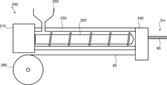
- an extrusion molding machine 200 illustrated in FIG. 8 can be used, and the above-mentioned cover materials 5m and 5n can be manufactured continuously at low cost by operating the extrusion molding machine 200.
- the extrusion molding machine 200 includes a rotating machine 210, a screw 220 rotated by the rotating machine 210, a cylinder 230 housing the screw 220, a mouthpiece 240, a soft material input port 250, and a reel 260 around which a core sheet 60 is wound. has.
- the screw 220 rotates, the soft material is sent toward the mouthpiece 240, passes through the opening of the mouthpiece 240, and is discharged with a cross section corresponding to the shape of the opening.
- the core material sheet 60 is also sent to the cap 240 in synchronization with the soft material.
- the core sheet 60 functions as a support base material that supports the soft material, and suppresses the flow of the soft material when passing through the opening of the mouthpiece 240.
- the shape of the extruded product (fastener stringers 2m, 2n) extruded from the extrusion molding machine 200 is stabilized.
- the extrusion molding machine 200 may have various configurations other than those shown.
- the extrusion molded product i.e., the cover material 5m, 5n including the seal portion 56
- the core sheet 60 is introduced into the soft material during extrusion molding, the soft material is attached to one or both sides of the core sheet 60 and supported, and the extrusion molded product (i.e., the cover including the seal portion 56 The shapes of the materials 5m and 5n are stabilized.
- the core sheet 60 is embedded in the soft material in such a manner that one side thereof is at least partially exposed or both sides thereof are not exposed.
- the cover materials 5m and 5n having a desired cross-sectional shape can be formed from the soft material and the core sheet.
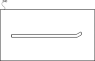
- the opening shape of the cap 240 is designed to define the outline of the cross-sectional shape perpendicular to the longitudinal direction of the cover members 5m and 5n.
- the base 240 shown in FIG. 9 is used to manufacture the cover materials 5m and 5n shown in FIG. 4. Bases with other opening shapes can also be used.
- the core sheet 60 is set to run at a predetermined position in the opening of the cap 240. In some cases, the core sheet is inserted so that one end (the inner end 68 described above) of the core sheet 60 in the lateral direction perpendicular to the extrusion direction of the extruded product (fastener stringers 2m, 2n) is embedded in the seal portion 56. 60 driving routes are set. One end of the core sheet 60 (the above-mentioned inner end 68) is positioned away from the sealing surface 58 of the sealing portion 56, and a soft portion is located between the one end of the core material sheet 60 (the above-mentioned inner end 68) and the sealing surface 58.
- the running path of the core sheet 60 can also be set so that the core sheet 57 is formed, and the same effect as described above can be obtained.
- the cover materials 5m, 5n may be bonded to the fastener tapes 3m, 3n so as to have the seal portions 56 at positions opposite to the fastener elements 4m, 4n.
- the cover materials 5m, 5n can be bonded to the fastener tapes 3m, 3n in such a manner that the seal portion 56 can be displaced away from and toward the fastener tapes 3m, 3n.
- the adhesive or adhesive layer used to bond the cover materials 5m, 5n and the fastener tapes 3m, 3n is preferably made of a water-resistant adhesive material. It is also possible to thermocompress the cover materials 5m, 5n and the fastener tapes 3m, 3n without using an adhesive material.
- step S1 and step S2 are performed continuously during the same period.
- step S1 and step S2 can also be performed discontinuously in different periods.
- cover materials 5m and 5n continuously extruded from the extrusion molding machine 200 are cut, wound onto a reel, etc., and stored. On different days and/or at different locations, the cover materials 5m and 5n previously produced and stored as described above are attached to the fastener tapes 3m and 3n.
- an adhesive is applied to at least one of the lower surface of the cover material 5m and the upper surface of the fastener tape 3m, or an adhesive layer is laminated thereon.
- the cover material 5m and the fastener tape 3m are laminated with an adhesive or an adhesive layer interposed therebetween, so that they are stuck together.
- the seal portion of the cover material can be appropriately positioned with respect to the fastener element.
- FIG. 12 it is also possible to individually bond the cover materials 5m and 5n to the fastener tapes 3m and 3n of the fastener chain in which the left and right water-permeable stringers are engaged.
- bonding the cover material to the fastener tape of the fastener chain entails and implies bonding the cover material to the fastener tape of the water-permeable stringer.
- the water permeable stringers 7m and 7n to which the cover materials 5m and 5n are bonded.
- the fastener tapes 3m, 3n have a folded part 302 which is folded back with respect to a tape main part 301, and fastener elements 4m, 4n are sewn to this folded part 302. Even if the water-permeable stringers 7m and 7n of different configurations are adopted in this way, the same effects as described above can be obtained as long as the above-mentioned characteristics are provided.
- the shapes of the cover materials 5m and 5n can also be changed in various ways.
- the seal portion 56 When forming the seal portion 56 as an inclined portion, the seal portion 56 may be formed into a tapered shape in the cross section in the longitudinal direction of the fastener stringers 2m, 2n, as shown in FIG. This narrows the vertical width of the sealing surface 58 of the sealing part 56, reducing the force required to move the slider 8 to engage the fastener elements 4m and 4n and bring the sealing parts 56 into a butt state. can be done.
- the inner end 68 of the core sheet 60 is embedded in the seal portion 56.
- the seal portion 56 may be shaped as or include a wall portion that stands vertically in the longitudinal cross section of the fastener stringers 2m, 2n.
- the wall portion extends in the longitudinal direction of the fastener stringers 2m, 2n, and has a pair of wall surfaces that define the width of the wall portion, one of which functions as a sealing surface 58.
- the height of the wall is adjustable.
- the cover materials 5m and 5n can also be formed as flat sheet materials. Even in such a case, the cover members 5m and 5n can have the seal portion 56 by bonding them in an appropriate positional relationship to the water-permeable stringers 7m and 7n.
- cover materials 5m and 5n can also be manufactured by a method other than extrusion molding.
- the symbols included in the claims are for reference only and should not be referred to for the purpose of limiting the scope of the claims.
Abstract
Fastener stringers (2m, 2n) comprising fastener tapes (3m, 3n), fastener elements (4m, 4n) disposed on the lateral edges (33) of the fastener tapes (3m, 3n), and covering materials (5m, 5n) formed from a soft material (99) and covering the fastener tapes (3m, 3n), the covering materials (5m, 5n) having seal parts (56) located on the reverse side of the fastener tapes (3m, 3n) from the fastener elements (4m, 4n) along the thickness direction of the fastener tapes (3m, 3n). The covering materials (5m, 5n) include flexible core sheets (60) extending in the longitudinal direction of the fastener stringers (2m, 2n). Each core sheet (60) is embedded in the soft material (99) so that one surface thereof is at least partly exposed or that neither surface thereof is exposed.
Description
本開示は、ファスナーストリンガー及びその製造方法に関する。
The present disclosure relates to a fastener stringer and a method for manufacturing the same.
撥水性を有する程度の安価なスライドファスナーや高い水密性又は気密性を確保できる高価なスライドファスナーが知られている。前者の一例としては、ファスナーテープにポリウレタンフィルムを貼り合わせたものが知られている。後者の一例としては、左右の射出成形エレメントの係合時に左右のファスナーテープの対向端部同士が突き合わされるものが知られている。
Inexpensive slide fasteners that are water repellent and expensive slide fasteners that are highly watertight or airtight are known. As an example of the former type, a zipper tape with a polyurethane film bonded thereto is known. As an example of the latter, it is known that the opposing ends of left and right fastener tapes are butted against each other when the left and right injection molded elements are engaged.
特許文献1には、合成樹脂又はゴムのような弾性材の被覆層を基布に付着したテープ部にファスナーエレメントを縫い付け、この縫い付け箇所で被覆層に薄肉部を形成することが開示されている(特許文献1の図1参照)。特許文献2には、水密・気密性ストリップに対してコイル状のモノフィラメントを縫い付けることが開示されている(特許文献2の図1参照)。
Patent Document 1 discloses that a fastener element is sewn to a tape portion on which a covering layer of an elastic material such as synthetic resin or rubber is attached to a base fabric, and a thin-walled portion is formed in the covering layer at this sewing location. (See FIG. 1 of Patent Document 1). Patent Document 2 discloses sewing a coiled monofilament onto a watertight/airtight strip (see FIG. 1 of Patent Document 2).
特許文献3には、ファスナーテープ(特許文献3の図1の符号11,12参照)にフィルム(特許文献3の図1の符号21,22参照)を貼り合わせ、かつ同文献の図1に示すようにフィルム同士を接触させることが開示されている。特許文献4の図15には、防水シール層(特許文献4の図15の符号4参照)にシール部(特許文献4の図15の符号13参照)を形成することが開示されている。特許文献5の図4には、折曲げ端縁(特許文献5の図4の符号7参照)を噛合い中心線(特許文献5の図4の符号8参照)よりも突出させることが開示されている。
Patent Document 3 discloses that a film (see numerals 21 and 22 in FIG. 1 of Patent Document 3) is attached to a fastener tape (see numerals 11 and 12 in FIG. 1 of Patent Document 3), and as shown in FIG. 1 of the same document. It is disclosed that the films are brought into contact with each other in this manner. FIG. 15 of Patent Document 4 discloses forming a seal portion (see reference numeral 13 in FIG. 15 of Patent Document 4) in a waterproof seal layer (see reference numeral 4 in FIG. 15 of Patent Document 4). FIG. 4 of Patent Document 5 discloses that the bent edge (see reference numeral 7 in FIG. 4 of Patent Document 5) is made to protrude beyond the engagement center line (see reference numeral 8 of FIG. 4 of Patent Document 5). ing.
特許文献6には、合成ゴム等から成る被覆層で支持テープが被覆されたスライドファスナーにおいて、ファスナーエレメントが係合する時、各被覆層の対向する縁部の密着領域が同文献の図1に示すように形成されることが開示されている。特許文献7及び8にも特許文献6と同種のスライドファスナーが開示されている。
Patent Document 6 discloses that in a slide fastener in which a support tape is covered with a coating layer made of synthetic rubber or the like, when the fastener elements are engaged, the contact areas of the opposing edges of each coating layer are as shown in FIG. 1 of the same document. It is disclosed that it is formed as shown. Slide fasteners similar to those in Patent Document 6 are also disclosed in Patent Documents 7 and 8.
冒頭で述べたように、撥水性を有する程度の安価なスライドファスナーや高い水密性又は気密性を確保できる高価なスライドファスナーが知られているが、これらの中間に位置付けられるスライドファスナーは市場に提供されていない。かかる事実に照らして、本願発明者は、低コストで量産し易く、かつより十分な水密性又は気密性を持つ新構造のスライドファスナーを提供するという新たな課題を見出した。
As mentioned at the beginning, there are known slide fasteners that are inexpensive enough to be water repellent and expensive slide fasteners that can ensure high watertightness or airtightness, but slide fasteners that are in between these are not available on the market. It has not been. In light of such facts, the inventors of the present application have found a new problem: to provide a slide fastener with a new structure that is easy to mass-produce at low cost and has more sufficient watertightness or airtightness.
本開示の一態様に係るファスナーストリンガーは、ファスナーテープと、ファスナーテープの側縁部に設けられたファスナーエレメントと、軟質材料から形成されると共にファスナーテープを被覆するカバー材にして、ファスナーテープの厚み方向においてファスナーテープに関してファスナーエレメントとは反対側の位置にシール部を有するカバー材を含む。カバー材は、ファスナーストリンガーの長手方向に延びる可撓性の芯材シートを含み、芯材シートは、その片面が少なくとも部分的に露出する態様又はその両面が露出しない態様で軟質材料に埋設される。
A fastener stringer according to one aspect of the present disclosure includes a fastener tape, a fastener element provided on a side edge of the fastener tape, and a cover material that is formed of a soft material and covers the fastener tape, and has a thickness of the fastener tape. The fastener tape includes a cover material having a seal portion at a location opposite the fastener element in the direction of the fastener tape. The cover material includes a flexible core sheet extending in the longitudinal direction of the fastener stringer, and the core sheet is embedded in the soft material in such a manner that one side thereof is at least partially exposed or both sides thereof are not exposed. .
幾つかの実施形態においては、カバー材は、ファスナーテープを支持する支持基材として構成される。
In some embodiments, the covering material is configured as a support substrate that supports the fastener tape.
幾つかの実施形態においては、ファスナーストリンガーの幅方向における芯材シートの一端がシール部に埋設される。ファスナーストリンガーの幅方向における芯材シートの一端が、ファスナーエレメントの上方の範囲内においてシール部のシール面から離れて位置付けられ、カバー材の幅方向において芯材シートの一端とシール面の間に軟質部が形成され得る。カバー材の幅方向における芯材シートの一端とシール面の間隔は、1cm以内であり得る。
In some embodiments, one end of the core sheet in the width direction of the fastener stringer is embedded in the seal portion. One end of the core material sheet in the width direction of the fastener stringer is positioned away from the sealing surface of the sealing part within the upper range of the fastener element, and a soft material is located between the one end of the core material sheet and the sealing surface in the width direction of the cover material. A section may be formed. The distance between one end of the core sheet and the sealing surface in the width direction of the cover material may be 1 cm or less.
幾つかの実施形態においては、芯材シートは、織物シート、編物シート、織編混在シート、紙製シート、不織布、又は金属箔である。
In some embodiments, the core sheet is a woven sheet, a knitted sheet, a mixed woven and knitted sheet, a paper sheet, a nonwoven fabric, or a metal foil.
幾つかの実施形態においては、シール部は、ファスナーテープから離れるように及び接近するように変位可能である。
In some embodiments, the seal portion is displaceable away from and toward the fastener tape.
幾つかの実施形態においては、カバー材は、ファスナーテープよりも幅広である。カバー材は、ファスナーストリンガーの幅方向においてファスナーテープよりもシール部から離れて位置し、ファスナーテープにより被覆されずに露出した露出面を有する取付部を有し得る。
In some embodiments, the covering material is wider than the fastener tape. The cover material may have a mounting portion located further away from the sealing portion than the fastener tape in the width direction of the fastener stringer and having an exposed surface not covered by the fastener tape.
幾つかの実施形態においては、シール部は、斜めに傾斜した傾斜部又は垂直に起立した壁部を含むように形状付けられる。
In some embodiments, the seal portion is shaped to include an oblique ramp or a vertical wall.
幾つかの実施形態においては、ファスナーエレメントは、ファスナーテープに対して取付糸によって縫い付けられたコイル状エレメントである。ファスナーテープは、カバー材により少なくとも部分的に被覆された主面を有し、主面において取付糸の縫い目がカバー材により被覆され得る。
In some embodiments, the fastener element is a coiled element sewn to the fastener tape by an attachment thread. The fastener tape has a major surface that is at least partially covered by a covering material, and the attachment thread seam can be covered by the covering material on the major surface.
本開示の別態様に係るファスナーストリンガーの製造方法は、可撓性の芯材シートが、その片面が少なくとも部分的に露出する態様又はその両面が露出しない態様で軟質材料に埋設されたカバー材を押出成形により形成する工程と、ファスナーエレメントが側縁部に設けられたファスナーテープに対してカバー材を貼り合わせてカバー材によりファスナーテープを支持する工程を含む。
A method for manufacturing a fastener stringer according to another aspect of the present disclosure includes a cover material in which a flexible core sheet is embedded in a soft material in such a manner that one side thereof is at least partially exposed or both sides thereof are not exposed. The method includes a step of forming by extrusion molding, and a step of bonding a cover material to a fastener tape having side edges provided with fastener elements and supporting the fastener tape with the cover material.
幾つかの実施形態においては、カバー材は、ファスナーテープに関してファスナーエレメントとは反対側の位置にシール部を有するようにファスナーテープに対して貼り合わされる。
In some embodiments, the cover material is laminated to the fastener tape such that the cover material has a seal at a location opposite the fastener element with respect to the fastener tape.
幾つかの実施形態においては、カバー材は、シール部がファスナーテープから離れるように及び接近するように変位可能である態様でファスナーテープに対して貼り合わされる。
In some embodiments, the covering material is affixed to the fastener tape in such a manner that the seal portion is movable away from and toward the fastener tape.
幾つかの実施形態においては、押出成形機からのカバー材の押出とファスナーテープへのカバー材の貼り合わせが、押出成形機と貼り合わせの位置の間でカバー材を切断することなく連続的に行われる。
In some embodiments, the extrusion of the covering material from the extruder and the application of the covering material to the fastener tape occur continuously without cutting the covering material between the extruder and the location of the application. It will be done.
本開示の一態様によれば、低コストで量産し易く、かつより十分な水密性又は気密性を持つ新構造のファスナーストリンガーを提供することができる。
According to one aspect of the present disclosure, it is possible to provide a fastener stringer with a new structure that is easy to mass-produce at low cost and has more sufficient watertightness or airtightness.
以下、図面を参照しつつ、様々な実施形態及び特徴について説明する。当業者は、過剰説明を要せず、各実施形態及び/又は各特徴を組み合わせることができ、この組み合わせによる相乗効果も理解可能である。実施形態間の重複説明は、原則的に省略する。参照図面は、発明の記述を主たる目的とするものであり、作図の便宜のために簡略化されている。各特徴は、本願に開示されたスライドファスナー及びその製造方法にのみ有効であるものではなく、本明細書に開示されていない他の様々なスライドファスナー及びその製造方法にも通用する普遍的な特徴として理解される。
Hereinafter, various embodiments and features will be described with reference to the drawings. Those skilled in the art can combine each embodiment and/or each feature without needing excessive explanation, and can also understand the synergistic effect of this combination. Duplicate explanations between embodiments will be omitted in principle. The reference drawings are primarily for the purpose of describing the invention and are simplified for ease of drawing. Each feature is not only effective for the slide fastener and its manufacturing method disclosed in this application, but is also a universal feature that is applicable to various other slide fasteners and its manufacturing method not disclosed in this specification. It is understood as
本願明細書では、スライドファスナー1を開閉させるスライダー8の移動方向を前後方向(図1の双頭矢印FB参照)とする。スライドファスナー1の幅方向に等しく、かつ前後方向に直交する方向を左右方向(図1の双頭矢印LR参照)とする。スライドファスナー1の厚み方向に等しく、かつ前後方向に直交する方向を上下方向とする。尚、上下方向は、前後方向及び左右方向の両方向に直交する。上下方向は、必ずしも鉛直方向(重力方向)を意味しない。例えば、スライドファスナー1の長手方向が鉛直方向に配される時、スライドファスナー1に関する上下方向は(鉛直方向に直交する)水平方向に含まれる。このように、本明細書で参照する方向は、鉛直方向とは無関係である。
In this specification, the moving direction of the slider 8 that opens and closes the slide fastener 1 is the front-rear direction (see double-headed arrow FB in FIG. 1). A direction that is equal to the width direction of the slide fastener 1 and perpendicular to the front-rear direction is the left-right direction (see double-headed arrow LR in FIG. 1). A direction that is equal to the thickness direction of the slide fastener 1 and perpendicular to the front-rear direction is defined as an up-down direction. Note that the up-down direction is orthogonal to both the front-back direction and the left-right direction. The vertical direction does not necessarily mean the vertical direction (direction of gravity). For example, when the longitudinal direction of the slide fastener 1 is arranged in the vertical direction, the vertical direction regarding the slide fastener 1 is included in the horizontal direction (perpendicular to the vertical direction). Thus, the directions referred to herein are independent of the vertical direction.
スライドファスナー1は、一定の左右幅で前後方向に長く延びる可撓性のある長尺パーツであり、左右一対のファスナーストリンガー2m,2nと、このファスナーストリンガー2m,2nを係合及び係合解除するためのスライダー8を有する。スライダー8の前進によって左右のファスナーストリンガー2m,2nが係合し、後述のシール部56同士の突き合わせによって液密シールが形成される。スライダー8の後進によって左右のファスナーストリンガー2m,2nが係合解除され、後述のシール部56同士の突き合わせも解消される(結果として、液密シールが消失する)。
The slide fastener 1 is a flexible long part that extends in the front-rear direction with a constant left-right width, and engages and disengages the left and right pair of fastener stringers 2m and 2n. It has a slider 8 for As the slider 8 moves forward, the left and right fastener stringers 2m and 2n engage with each other, and a liquid-tight seal is formed by abutting the seal portions 56, which will be described later. As the slider 8 moves backward, the left and right fastener stringers 2m and 2n are disengaged, and the butt between the seal portions 56, which will be described later, is also eliminated (as a result, the liquid-tight seal disappears).
ファスナーストリンガー2m,2nは、一定の左右幅で前後方向に長く延びる可撓性のある長尺パーツであり、透水性ストリンガー7m,7nと、これに対して貼り合わされたカバー材5m,5nを含む。透水性ストリンガー7m,7n及びカバー材5m,5nも、一定の左右幅で前後方向に長く延びる可撓性のある長尺パーツである。透水性ストリンガー7m,7nは、透水性のファスナーテープ3m,3nと、ファスナーテープ3m,3nの側縁部33に設けられたファスナーエレメント4m,4nを含む。ファスナーテープ3m,3nは、一定の左右幅で前後方向に長く延びる可撓性のある長尺パーツである。
The fastener stringers 2m and 2n are flexible long parts that extend in the front and back direction with a constant left and right width, and include water permeable stringers 7m and 7n and cover materials 5m and 5n bonded thereto. . The water- permeable stringers 7m, 7n and the cover materials 5m, 5n are also flexible long parts that extend in the front-rear direction with a constant left-right width. The water- permeable stringers 7m, 7n include water- permeable fastener tapes 3m, 3n, and fastener elements 4m, 4n provided on the side edges 33 of the fastener tapes 3m, 3n. The fastener tapes 3m and 3n are flexible long parts that extend long in the front and back direction with a constant left and right width.
ファスナーテープ3m,3nは、透水性を有し、液体(例えば、水)の浸透及び透過を許容し、例えば、織布又は編布又は織編混在布である。詳細に説明すれば、ファスナーテープの組織及びこれを構成する糸(例えば、緯糸及び経糸)が液体を吸い、これにより液体の浸透及び透過が生じてしまう。織布の形態では、ファスナーテープ3m,3nが多数本の経糸と少なくとも一方の緯糸を含む。緯方向で隣接する経糸の間に糸の密度が疎なスポットが形成され、経方向で隣接する緯糸部分の間にも糸密度が疎なスポットが形成され、液体の浸透に寄与し得る。編布の形態においても網糸同士の間に糸密度が疎なスポットが形成され、液体の浸透に寄与し得る。
The fastener tapes 3m and 3n have water permeability and allow penetration and permeation of liquid (for example, water), and are, for example, woven fabrics, knitted fabrics, or woven/knitted fabrics. Specifically, the structure of the fastener tape and its constituent yarns (for example, weft and warp yarns) absorb liquid, resulting in liquid penetration and permeation. In the form of a woven fabric, the fastener tapes 3m and 3n include a large number of warp yarns and at least one weft yarn. Spots with a sparse yarn density are formed between warp yarns adjacent in the weft direction, and spots with a sparse yarn density are also formed between weft portions adjacent in the warp direction, which can contribute to liquid penetration. Even in the form of a knitted fabric, spots with a sparse thread density are formed between the mesh yarns, which can contribute to liquid penetration.
ファスナーエレメント4m,4nは、ファスナーテープ3m,3nに対して取付糸44によって縫い付けられたコイル状エレメントであり、典型的にはファスナーテープ3m,3nの片方の主面上に配置されるようにその側縁部に縫い付けられる。この目的のために単環縫、二重環縫といった任意の縫製方法を採用可能である。コイル状エレメントは、螺旋状に巻かれたモノフィラメントから構成され、モノフィラメントの部分間に隙間を有し、従って、透水性を有する。コイル状エレメントは、詳細には、螺旋状に巻かれたモノフィラメントの一巻きに等しいエレメント単位U1が前後方向に連続して形成される(図3参照)。エレメント単位U1は、上下方向に延びる頭部41と、頭部41の上下端に各々が連結された一対の脚部42と、隣接するエレメント単位U1間で脚部42同士を連結する連結部43を有する。前後方向において頭部41が脚部42よりも適度に幅広に成形されており、従って、左右のファスナーエレメント4m,4nの頭部41同士が係合及び係合解除可能である。他の種類のファスナーエレメントも採用可能である。コイル状エレメントの螺旋状のモノフィラメントの中空部に芯紐を導入しても良いが省略可能である。
The fastener elements 4m, 4n are coil-shaped elements sewn to the fastener tapes 3m, 3n by an attachment thread 44, and are typically arranged on one main surface of the fastener tapes 3m, 3n. sewn on its side edges. For this purpose, any sewing method such as single chain stitch or double chain stitch can be employed. The coiled element is constructed from a helically wound monofilament with gaps between the monofilament sections and is therefore water permeable. Specifically, the coiled element is formed by an element unit U1 that is equivalent to one turn of a helically wound monofilament and is continuously formed in the front-rear direction (see FIG. 3). The element unit U1 includes a head 41 extending in the vertical direction, a pair of legs 42 each connected to the upper and lower ends of the head 41, and a connecting portion 43 connecting the legs 42 between adjacent element units U1. has. The head 41 is formed to be appropriately wider than the leg 42 in the front-rear direction, so that the heads 41 of the left and right fastener elements 4m and 4n can be engaged with and disengaged from each other. Other types of fastener elements can also be employed. A core string may be introduced into the hollow part of the spiral monofilament of the coiled element, but this can be omitted.
図示例を含む幾つかの場合、カバー材5m,5nは、ファスナーテープ3m,3nよりも幅広で有り、その幅方向において、内側部53、取付部54、及び中間部55に区分可能であり得る。中間部55は、内側部53から連なり、取付部54は、中間部55から連なる。左右のカバー材5m,5nの各内側部53は、左右のファスナーエレメント4m,4nが係合する時にお互いに突き合わされるシール部56を含む。内側部53は、ファスナーテープ3m,3nの一方の主面に部分的に貼り合わされ得る。中間部55は、その全体においてファスナーテープ3m,3nの一方の主面に貼り合わされ得る。カバー材5m,5nの内側部53と中間部55の境界は、図4に示すようにファスナーエレメント4m,4nの連結部43に接し、スライドファスナー1の幅方向に直交する平面P1に定めることができる。カバー材5m,5nの中間部55と取付部54の境界は、図5に示すようにファスナーテープ3m,3nの外端面39に接し、スライドファスナー1の幅方向に直交する平面P2に定めることができる。
In some cases, including the illustrated example, the cover materials 5m and 5n are wider than the fastener tapes 3m and 3n, and may be separable into an inner portion 53, an attachment portion 54, and an intermediate portion 55 in the width direction. . The intermediate portion 55 continues from the inner portion 53, and the attachment portion 54 continues from the intermediate portion 55. Each inner side portion 53 of the left and right cover members 5m, 5n includes a seal portion 56 that abuts against each other when the left and right fastener elements 4m, 4n are engaged. The inner part 53 may be partially bonded to one main surface of the fastener tapes 3m and 3n. The entire intermediate portion 55 may be bonded to one main surface of the fastener tapes 3m and 3n. As shown in FIG. 4, the boundary between the inner part 53 and the intermediate part 55 of the cover materials 5m, 5n can be defined on a plane P1 that is in contact with the connecting part 43 of the fastener elements 4m, 4n and perpendicular to the width direction of the slide fastener 1. can. As shown in FIG. 5, the boundary between the intermediate portion 55 of the cover materials 5m, 5n and the attachment portion 54 can be defined on a plane P2 that is in contact with the outer end surface 39 of the fastener tapes 3m, 3n and perpendicular to the width direction of the slide fastener 1. can.
カバー材5m,5nの取付部54は、ファスナーテープ3m,3nに貼り合わされず、従って、ファスナーテープ3m,3nにより被覆されずに露出した露出面95を有する。取付部54は、ファスナーストリンガー2m,2nの幅方向においてファスナーテープ3m,3nよりもシール部56から離れて位置する。衣類、鞄、テントといった対象物品の開口部にファスナーストリンガー2m,2nを(例えば、熱圧着等の方法で)取り付けるために取付部54の片面又は両面を用いることができる。
The mounting portions 54 of the cover materials 5m, 5n are not bonded to the fastener tapes 3m, 3n, and therefore have exposed surfaces 95 that are not covered by the fastener tapes 3m, 3n. The attachment portion 54 is located further away from the seal portion 56 than the fastener tapes 3m, 3n in the width direction of the fastener stringers 2m, 2n. One or both sides of the attachment part 54 can be used to attach the fastener stringers 2m, 2n (for example, by a method such as thermocompression bonding) to an opening of a target article such as clothing, a bag, or a tent.
スライドファスナー1は、ファスナーエレメント4m,4nが係合した状態において中心面CPを持つことができる。中心面CPは、スライドファスナー1の幅方向に直交する平面である。また、中心面CPは、スライドファスナー1の幅方向においてファスナーエレメント4m,4nの係合した各頭部41の中心に設定される。上述した各平面P1,P2は、中心面CPに対して平行な平面の一つである。
The slide fastener 1 can have a central plane CP in a state in which the fastener elements 4m and 4n are engaged. The center plane CP is a plane perpendicular to the width direction of the slide fastener 1. Moreover, the center plane CP is set at the center of each head 41 engaged with the fastener elements 4m and 4n in the width direction of the slide fastener 1. Each of the planes P1 and P2 described above is one plane parallel to the central plane CP.
カバー材5m,5nは、ファスナーテープ3m,3nを介した液体の浸透及び透過を阻止するべくファスナーテープ3m,3nを(直に)被覆し(換言すれば、ファスナーテープ3m,3nの直上に積層され)、かつファスナーテープ3m,3nの厚み方向においてファスナーテープ3m,3nに関してファスナーエレメント4m,4nとは反対側の位置(例えば、その上方の位置)にシール部56を有する(図4参照)。例えば、ファスナーエレメント4m,4nがファスナーテープ3m,3nの下方の位置に設けられる場合、シール部56は、ファスナーテープ3m,3nの上方の位置に設けられる。好ましくは、平面視して、シール部は、ファスナーエレメントに覆われている。言い換えると、シール部は、図4に示すようにファスナーエレメント4m,4nの連結部43に接し、スライドファスナー1の幅方向に直交する平面P1よりも内側(内端面38側)に設けられている。
The cover materials 5m and 5n cover (directly) the fastener tapes 3m and 3n in order to prevent liquid penetration and permeation through the fastener tapes 3m and 3n (in other words, they are laminated directly on top of the fastener tapes 3m and 3n). and has a sealing portion 56 at a position opposite to (for example, above) the fastener elements 4m, 4n with respect to the fastener tapes 3m, 3n in the thickness direction of the fastener tapes 3m, 3n (see FIG. 4). For example, when the fastener elements 4m, 4n are provided below the fastener tapes 3m, 3n, the seal portion 56 is provided above the fastener tapes 3m, 3n. Preferably, the seal portion is covered with a fastener element in plan view. In other words, the seal portion is in contact with the connecting portion 43 of the fastener elements 4m, 4n, as shown in FIG. .
各カバー材5m,5nは、軟質材料99から形成され、詳細には、液体の浸透及び透過を許容しない軟質材料99(例えば、ゴム、エラストマー、樹脂(例えば、ポリウレタン)又はこれらの混合物)から形成される。このカバー材5m,5nの防水性のおかげで、透水性ストリンガー7m,7nの透水性に関わらずファスナーストリンガー2m,2nの防水性が確保される(即ち、ファスナーストリンガー2m,2nが防水ストリンガーとして機能し、スライドファスナー1が防水ファスナーとして機能する)。軟質材料99は、ゴム、エラストマー、樹脂といった主材料に加えて、その物理的又は化学的な特性の向上又は改良のために1以上の添加物を含むことができる。軟質材料99は、上述の主材料に加えて顔料(無機顔料、有機顔料)を含むこともでき、これによりカバー材がその顔料に応じた所望の色に着色される。
Each of the cover materials 5m and 5n is formed from a soft material 99, and in particular, from a soft material 99 that does not allow penetration or permeation of liquid (e.g., rubber, elastomer, resin (e.g., polyurethane), or a mixture thereof). be done. Thanks to the waterproofness of the cover materials 5m and 5n, the waterproofness of the zipper stringers 2m and 2n is ensured regardless of the water permeability of the water permeable stringers 7m and 7n (that is, the zipper stringers 2m and 2n function as waterproof stringers). However, the slide fastener 1 functions as a waterproof fastener). In addition to the main material such as rubber, elastomer, or resin, the soft material 99 can include one or more additives to enhance or improve its physical or chemical properties. The soft material 99 can also contain pigments (inorganic pigments, organic pigments) in addition to the above-mentioned main materials, so that the cover material is colored in a desired color according to the pigment.
なお、スライドファスナー1の防水性能(防水レベル)は、ファスナーストリンガー2m,2nの構成要素の材料、厚み、密度といった様々な内的パラメータに依存し、また、スライドファスナー1に付与される水圧といった外的パラメータにも依存する。スライドファスナー1は、冒頭で述べた撥水性を有する程度の安価なスライドファスナーと高い水密性又は気密性を確保できる高価なスライドファスナーの中間の防水性能を有するように設計され得るが、この防水レベルに限らず、これよりも低い又は高い防水レベルを有し得る。
The waterproof performance (waterproof level) of the slide fastener 1 depends on various internal parameters such as the material, thickness, and density of the components of the fastener stringers 2m and 2n, and also depends on external parameters such as the water pressure applied to the slide fastener 1. It also depends on the target parameters. The slide fastener 1 can be designed to have a waterproof performance between an inexpensive slide fastener that has water repellency as described at the beginning and an expensive slide fastener that can ensure high watertightness or airtightness. However, the waterproof level may be lower or higher than this.
本実施形態においては、カバー材5m,5nは、ファスナーテープ3m,3nを支持する支持基材として構成される(図4及び図5参照)。即ち、ファスナーテープ3m,3nによりカバー材5m,5nが支持されるのではなく、カバー材5m,5nによってファスナーテープ3m,3nが支持される。この目的のためにカバー材5m,5nは、ファスナーテープ3m,3nよりも低い可撓性を有する。尚、カバー材5m,5nは、ファスナーテープ3m,3nよりも厚く形成されていても良い。カバー材5m,5nは、所望のシール性能を有するべく所定の厚み以上に形成され得る。
In this embodiment, the cover materials 5m and 5n are configured as support base materials that support the fastener tapes 3m and 3n (see FIGS. 4 and 5). That is, the cover materials 5m and 5n are not supported by the fastener tapes 3m and 3n, but the fastener tapes 3m and 3n are supported by the cover materials 5m and 5n. For this purpose, the covering material 5m, 5n has a lower flexibility than the fastener tape 3m, 3n. Note that the cover materials 5m and 5n may be formed thicker than the fastener tapes 3m and 3n. The cover materials 5m and 5n may be formed to have a predetermined thickness or more in order to have desired sealing performance.
本実施形態においては、カバー材5m,5nは、ファスナーストリンガー2m,2nの長手方向に延びる可撓性の芯材シート60を含む。更には、芯材シート60は、その片面が少なくとも部分的に露出する態様又はその両面が露出しない態様で軟質材料99に埋設される。かかる構成によれば、芯材シート60によって軟質材料99が支持され、シール部56を含めてカバー材5m,5nの形状が安定する。非限定の効果として、ファスナーテープ3m,3nとして量産可能な安価なものを採用することが許され、スライドファスナー1の低コスト化を促進することができる。なお、芯材シート60は、ファスナーテープ3m,3nを支持するために、スライドファスナー1(同じくファスナーストリンガー2m,2n)の長手方向に延びる。この芯材シート60の片面又は両面に層状の軟質材料99が付着して支持される(図4参照)。芯材シート60の片面が露出する場合、この露出面と反対側にある芯材シート60の片面は、露出しない。
In this embodiment, the cover materials 5m, 5n include a flexible core sheet 60 extending in the longitudinal direction of the fastener stringers 2m, 2n. Furthermore, the core sheet 60 is embedded in the soft material 99 in such a manner that one side thereof is at least partially exposed or both sides thereof are not exposed. According to this configuration, the soft material 99 is supported by the core sheet 60, and the shape of the cover materials 5m and 5n including the seal portion 56 is stabilized. As a non-limiting effect, it is possible to use inexpensive fastener tapes 3m and 3n that can be mass-produced, and it is possible to promote cost reduction of the slide fastener 1. Note that the core sheet 60 extends in the longitudinal direction of the slide fastener 1 (also the fastener stringers 2m, 2n) in order to support the fastener tapes 3m, 3n. A layered soft material 99 is attached to and supported on one or both sides of the core sheet 60 (see FIG. 4). When one side of the core sheet 60 is exposed, the other side of the core sheet 60 opposite to this exposed side is not exposed.
芯材シート60の片面のみに軟質材料99が付着する場合、芯材シート60は、軟質材料99からその反対側の片面において露出する。芯材シート60の両面に軟質材料99が付着する場合、芯材シート60は、その両面において軟質材料99により被覆されて露出しない。なお、芯材シート60の面が露出するか否かは、カバー材5m,5n単体に関して外観から視認できるか否かに基づく。軟質材料99は、2次元的な広がりを有し、スライドファスナー1の幅方向及び長手方向の両方向においてカバー材5m,5nの断面にて層又はシートとして観察可能である。
When the soft material 99 is attached to only one side of the core sheet 60, the core sheet 60 is exposed on the opposite side from the soft material 99. When the soft material 99 is attached to both sides of the core sheet 60, the core sheet 60 is covered with the soft material 99 on both sides and is not exposed. Note that whether or not the surface of the core material sheet 60 is exposed is based on whether or not the cover materials 5m and 5n can be visually recognized from the outside. The soft material 99 has a two-dimensional extent and can be observed as a layer or sheet in the cross section of the cover materials 5m and 5n in both the width direction and the longitudinal direction of the slide fastener 1.
ファスナーテープ3m,3nは、ファスナーエレメントが織り込まれていない種類のファスナーテープ(例えば、コイルエレメントが縫い付けられたファスナーテープ)であり得る。上述のようにファスナーテープ3m,3nではなくカバー材5m,5nが支持基材として働く。従って、安価に量産されたファスナーテープ(同じく透水性ストリンガー7m,7n)の使用が許され、スライドファスナー1の低コスト化が促進される。安価なファスナーテープ3m,3nの高い柔軟性が、カバー材5m,5nの低い柔軟性により相殺又は補償されると言える。
The fastener tapes 3m and 3n may be a type of fastener tape in which a fastener element is not woven (for example, a fastener tape in which a coil element is sewn). As described above, the cover materials 5m and 5n serve as supporting base materials instead of the fastener tapes 3m and 3n. Therefore, the use of inexpensively mass-produced fastener tapes (water- permeable stringers 7m and 7n) is allowed, and cost reduction of the slide fastener 1 is promoted. It can be said that the high flexibility of the inexpensive fastener tapes 3m and 3n is offset or compensated for by the low flexibility of the cover materials 5m and 5n.
尚、ファスナーエレメント(端的には、モノフィラメントが螺旋状に巻かれたコイルエレメント)がファスナーテープに織り込まれた種類のファスナーテープでは、ファスナーテープの緯糸との係合によってファスナーエレメントがテープ組織に組み込まれる。この場合、ファスナーテープの柔軟性が低下し、ポリウレタンコーティングといった軟質材料の支持基材として用いることができるが、高価になる傾向がある。
In addition, in a type of fastener tape in which a fastener element (simply referred to as a coil element in which a monofilament is spirally wound) is woven into the fastener tape, the fastener element is incorporated into the tape structure by engagement with the weft of the fastener tape. . In this case, the flexibility of the fastener tape is reduced and it can be used as a support substrate for soft materials such as polyurethane coatings, but it tends to be expensive.
ファスナーテープ3m,3nは、テープ上面31とテープ下面32を有し、これらによって画定される厚みを有する(図4参照)。テープ上面31とテープ下面32は、ファスナーテープ3m,3nの厚みを画定する主面である。ファスナーテープ3m,3nの厚み方向は、テープ上面31及びテープ下面32に直交する方向である。ファスナーエレメント4m,4nは、ファスナーテープ3m,3nのテープ下面32に対して縫い付けられている。カバー材5m,5nは、上面51と下面52を有し、これらによって画定される厚みを持つ。カバー材5m,5nは、ファスナーテープ3m,3nのテープ上面31に対して貼り合わされており、典型的には、接着剤又は接着層を介して貼り合わされている。ファスナーテープ3m,3nからのカバー材5m,5nの剥離のためには強い力が必要であり、無理に剥離しようとすると、一方又は両方を破壊させ得る。有利には、ファスナーテープ3m,3nのテープ上面31においてカバー材5m,5nにより取付糸44の縫い目が被覆され、これに応じてファスナーテープ3m,3nのテープ下面32側でファスナーエレメント4m,4nの位置が安定化する。この結果、ファスナーエレメント4m,4nの係合時のシール部56同士の突き合わせが強化され、スライドファスナー1の防水性が高められる。
The fastener tapes 3m and 3n have a tape upper surface 31 and a tape lower surface 32, and have a thickness defined by these (see FIG. 4). The tape upper surface 31 and the tape lower surface 32 are main surfaces that define the thickness of the fastener tapes 3m and 3n. The thickness direction of the fastener tapes 3m and 3n is a direction perpendicular to the tape upper surface 31 and the tape lower surface 32. The fastener elements 4m, 4n are sewn to the tape lower surfaces 32 of the fastener tapes 3m, 3n. The cover materials 5m and 5n have an upper surface 51 and a lower surface 52, and have a thickness defined by these. The cover materials 5m and 5n are bonded to the tape upper surfaces 31 of the fastener tapes 3m and 3n, typically via an adhesive or an adhesive layer. A strong force is required to peel the cover materials 5m, 5n from the fastener tapes 3m, 3n, and if you try to forcefully peel them off, one or both may be destroyed. Advantageously, the seams of the attachment threads 44 are covered by the covering material 5m, 5n on the tape upper surface 31 of the fastener tapes 3m, 3n, and accordingly the seams of the fastener elements 4m, 4n are covered on the tape lower surface 32 side of the fastener tapes 3m, 3n. The position is stabilized. As a result, the abutment between the seal portions 56 when the fastener elements 4m and 4n are engaged is strengthened, and the waterproofness of the slide fastener 1 is enhanced.
スライドファスナー1(同じくファスナーストリンガー2m,2n)の幅方向において、ファスナーテープ3m,3nは、内端面38(図4参照)と外端面39(図5参照)を有する。左右のファスナーエレメント4m,4nが係合する時、左右のファスナーテープ3m,3nの内端面38同士が対向して配置され、両者の間の隙間9が形成される。平面視して隙間9を被覆する位置(端的には、隙間9の上方位置)でシール部56同士が突き合わされて液密シールが形成され、これが形成されない場合の隙間9を介した液体の浸透及び透過が阻止される。
In the width direction of the slide fastener 1 (also the fastener stringers 2m, 2n), the fastener tapes 3m, 3n have an inner end surface 38 (see FIG. 4) and an outer end surface 39 (see FIG. 5). When the left and right fastener elements 4m, 4n are engaged, the inner end surfaces 38 of the left and right fastener tapes 3m, 3n are arranged to face each other, and a gap 9 is formed between them. A liquid-tight seal is formed by abutting the seal portions 56 against each other at a position covering the gap 9 in plan view (in short, at a position above the gap 9), and if this is not formed, the liquid permeates through the gap 9. and transmission is prevented.
スライドファスナー1(同じくファスナーストリンガー2m,2n)の幅方向において、カバー材5m,5nは、内端面としてのシール面58(図4参照)と外端面59(図5参照)を有する。同じく、芯材シート60は、内端68(図4参照)と外端69(図5参照)を有する。カバー材5mのシール面58は、ファスナーテープ3mの内端面38よりもファスナーテープ3mのテープ外方に位置する。同様、カバー材5nのシール面58は、ファスナーテープ3nの内端面38よりもファスナーテープ3nのテープ外方に位置する。カバー材5mの外端面59は、ファスナーテープ3mの外端面39よりもファスナーテープ3mのテープ外方に位置する。同様、カバー材5nの外端面59は、ファスナーテープ3nの外端面39よりもファスナーテープ3nのテープ外方に位置する。これにより、スライドファスナー1を相手側の生地に溶着し易くなる。尚、テープ外方は、あるファスナーテープの主面上の位置から主面外の位置にファスナーテープの長手方向に延びるその側縁に交差して延びる方向を意味する。内端を一端と呼び、外端を他端と呼ぶこともできる。内端面を一端面と呼び、外端面を他端面と呼ぶこともできる。
In the width direction of the slide fastener 1 (also the fastener stringers 2m, 2n), the cover materials 5m, 5n have a sealing surface 58 (see FIG. 4) as an inner end surface and an outer end surface 59 (see FIG. 5). Similarly, the core sheet 60 has an inner end 68 (see FIG. 4) and an outer end 69 (see FIG. 5). The sealing surface 58 of the cover material 5m is located further outward of the fastener tape 3m than the inner end surface 38 of the fastener tape 3m. Similarly, the sealing surface 58 of the cover material 5n is located further outward of the fastener tape 3n than the inner end surface 38 of the fastener tape 3n. The outer end surface 59 of the cover material 5m is located further outward of the fastener tape 3m than the outer end surface 39 of the fastener tape 3m. Similarly, the outer end surface 59 of the cover material 5n is located further outward of the fastener tape 3n than the outer end surface 39 of the fastener tape 3n. This makes it easier to weld the slide fastener 1 to the fabric of the other party. Note that the tape outward means a direction extending from a position on the main surface of a certain fastener tape to a position outside the main surface, intersecting the side edges extending in the longitudinal direction of the fastener tape. The inner end may be referred to as one end and the outer end may be referred to as the other end. The inner end surface can also be called one end surface, and the outer end surface can also be called the other end surface.
幾つかの場合、芯材シート60の内端68がシール部56に埋設され、シール部56の硬さが増し、そのシール性能が高められる。好適には、芯材シート60の内端68が、ファスナーエレメント4m,4nの上方の範囲(ファスナーエレメント4m,4nの幅W4)内においてシール部56のシール面58から離れて位置付けられ、芯材シート60の内端68とシール面58の間に軟質部57が形成され、シール部56が適度な軟らかさを持つことができる。これにより、ファスナーエレメント4m,4n同士を係合させ、かつシール部56同士を突き合わせた状態にするべくスライダー8を動かすことに必要な力が低減され得る。なお、芯材シート60が織物又は編物又は紙である場合、軟質材料99(例えば、その層状部分、シール部56、及び/又は、軟質部57)に繊維が混入し得る。
In some cases, the inner end 68 of the core sheet 60 is embedded in the seal portion 56, increasing the hardness of the seal portion 56 and enhancing its sealing performance. Preferably, the inner end 68 of the core sheet 60 is positioned away from the seal surface 58 of the seal portion 56 within the range above the fastener elements 4m, 4n (width W4 of the fastener elements 4m, 4n), and A soft portion 57 is formed between the inner end 68 of the sheet 60 and the sealing surface 58, so that the sealing portion 56 can have appropriate softness. Thereby, the force required to move the slider 8 to engage the fastener elements 4m, 4n and bring the seal portions 56 into abutment can be reduced. Note that when the core sheet 60 is a woven fabric, a knitted fabric, or paper, fibers may be mixed into the soft material 99 (for example, its layered portion, seal portion 56, and/or soft portion 57).
スライドファスナー1(同じくカバー材5m,5n)の幅方向における芯材シート60の内端68とシール面58の間隔S57(図4参照)は、同じ方向におけるファスナーエレメント4m,4nの横幅W4(図4参照)の1/2以下又は1/3以下であり得る。これにより上述の効果が促進される。典型例では、スライドファスナー1(同じくカバー材5m,5n)の幅方向における芯材シート60の内端68とシール面58の間隔は、1cm以内又は5mm以内又は3mm以内又は2mm以内である。
The distance S57 between the inner end 68 of the core sheet 60 and the sealing surface 58 in the width direction of the slide fastener 1 (also cover materials 5m and 5n) (see FIG. 4) is equal to the width W4 of the fastener elements 4m and 4n in the same direction (see FIG. 4) may be 1/2 or less or 1/3 or less. This promotes the above-mentioned effects. In a typical example, the distance between the inner end 68 of the core sheet 60 and the sealing surface 58 in the width direction of the slide fastener 1 (also the cover materials 5m, 5n) is within 1 cm, within 5 mm, within 3 mm, or within 2 mm.
芯材シート60として、織物シート、編物シート、織編混在シート、紙製シート、不織布、又は金属箔を用いることができる。織物シート、編物シート、織編混在シート、紙製シート、不織布、又は金属箔は、いずれも可撓性を有する。また、織物シート、編物シート、織編混在シート、紙製シート、不織布、又は金属箔は、有利には、透水性ストリンガー7m,7nに含まれるファスナーテープ3m,3nよりも幅広である。これにより十分な範囲又は程度において軟質材料99を支持することができる。
As the core material sheet 60, a woven fabric sheet, a knitted fabric sheet, a woven/knitted mixed sheet, a paper sheet, a nonwoven fabric, or a metal foil can be used. A woven sheet, a knitted sheet, a mixed woven and knitted sheet, a paper sheet, a nonwoven fabric, or a metal foil all have flexibility. The woven sheet, knitted sheet, mixed woven sheet, paper sheet, non-woven fabric or metal foil is also advantageously wider than the fastener tapes 3m, 3n included in the water- permeable stringers 7m, 7n. This makes it possible to support the soft material 99 to a sufficient extent or extent.
織物シート、編物シート、又は織編混在シートを芯材シート60として用いる場合、カバー材5m,5nは、その芯材シート60の織及び/又は編組織に応じた模様を持つことができ、一般的なスライドファスナーに似た外観をスライドファスナー1に持たせることができる。例えば、織物シートが綾織組織を含む時、カバー材5m,5nは、傾斜線が長手方向に連続して配置された模様を持つ。尚、芯材シート60の織物シートとして、透水性ストリンガー7m,7nに含まれるファスナーテープ3m,3nと同一組織のファスナーテープを用いることができ、材料コスト低減が促進され得る。
When a woven fabric sheet, a knitted fabric sheet, or a mixed woven and knitted sheet is used as the core material sheet 60, the cover materials 5m and 5n can have a pattern corresponding to the weave and/or knitted structure of the core material sheet 60. The slide fastener 1 can have an appearance similar to a traditional slide fastener. For example, when the fabric sheet includes a twill weave structure, the covering materials 5m and 5n have a pattern in which inclined lines are continuously arranged in the longitudinal direction. In addition, as the fabric sheet of the core material sheet 60, a fastener tape having the same structure as the fastener tapes 3m and 3n included in the water- permeable stringers 7m and 7n can be used, and material cost reduction can be promoted.
シール部56は、ファスナーテープ3m,3nのテープ上面31から離れるように及び接近するように上下方向に沿って変位可能であり得る(図4参照)。詳細には、内側部53は、ファスナーエレメント4m,4nの反対側でファスナーテープ3m,3nの側縁部33に対して部分的に貼り合わされておらず、結果として上述のように上下方向に沿って変位可能なシール部56が形成され、スライダー8の移動に要する力の低減が促進される。尚、左右のファスナーエレメント4m,4nが係合する時、左右のカバー材5m,5nのシール部56同士が突き合わされて水密シールが形成される。ファスナーエレメント4m,4nが係合する過程でシール部56同士が押し合う結果、図4の点線で示すような位置から実線で示す位置に各シール部56がファスナーエレメント4m,4nから離れるように上方に変位し得る。
The seal portion 56 may be movable in the vertical direction away from and toward the tape upper surface 31 of the fastener tapes 3m and 3n (see FIG. 4). Specifically, the inner part 53 is not partially bonded to the side edge part 33 of the fastener tapes 3m, 3n on the opposite side of the fastener elements 4m, 4n, and as a result, the inner part 53 is not bonded to the side edge part 33 of the fastener tapes 3m, 3n on the opposite side of the fastener elements 4m, 4n. A displaceable seal portion 56 is formed, which helps reduce the force required to move the slider 8. Incidentally, when the left and right fastener elements 4m and 4n are engaged, the seal portions 56 of the left and right cover materials 5m and 5n are butted against each other to form a watertight seal. As a result of the seal portions 56 being pressed against each other during the engagement process of the fastener elements 4m, 4n, each seal portion 56 moves upwardly away from the fastener elements 4m, 4n from the position shown by the dotted line in FIG. 4 to the position shown by the solid line. can be displaced.
シール部56を様々な形状に成形することができる。図4に図示の如く斜めに傾斜した傾斜部として又はこれを含むようにシール部56を形状付けることができる。シール部56は、テープ外方に延びるに応じてファスナーテープ3m,3nのテープ上面31から徐々に上方に離れる。同様、シール部56に含まれる芯材シート60の部分は、テープ外方に延びるに応じてファスナーテープ3m,3nのテープ上面31から徐々に上方に離れる。尚、スライダー8内においては空間的に制約されるため、左右のシール部56が、各々、ファスナーテープ3m,3nに対して少なくとも部分的に接触した状態になり得る(図6参照)。
The seal portion 56 can be formed into various shapes. The seal portion 56 may be configured as or include an obliquely sloped portion as shown in FIG. The seal portion 56 gradually separates upward from the tape upper surface 31 of the fastener tapes 3m, 3n as the tape extends outward. Similarly, the portion of the core sheet 60 included in the seal portion 56 gradually separates upward from the tape upper surface 31 of the fastener tapes 3m, 3n as the tape extends outward. In addition, since the inside of the slider 8 is spatially restricted, the left and right seal portions 56 may come into at least partial contact with the fastener tapes 3m and 3n, respectively (see FIG. 6).
スライダー8は、ファスナーストリンガー2m,2nの係合及び係合解除のために設計される。典型的には、スライダー8は、図6に示すように、上翼板81、下翼板82、及びこれらを連結するべく上下に延びる連結柱(不図示)を有し、これによりY字状のエレメント通路が画定される。下翼板82の左右側縁に上方に起立したフランジ壁83が設け、スライダー8の幅方向において左右のファスナーエレメント4m,4nの移動を規制することもできる。
The slider 8 is designed for engaging and disengaging the fastener stringers 2m and 2n. Typically, as shown in FIG. 6, the slider 8 has an upper wing plate 81, a lower wing plate 82, and a connecting column (not shown) that extends up and down to connect these, thereby forming a Y-shape. An element passageway is defined. Flange walls 83 that stand upward are provided on the left and right side edges of the lower wing plate 82 to restrict movement of the left and right fastener elements 4m and 4n in the width direction of the slider 8.
図7に示す手順でファスナーストリンガー2m,2nを製造することができる。ファスナーストリンガー2m,2nを係合することにより防水チェーンが製造される。防水チェーンの係合したファスナーエレメントに対してスライダーを係合させることによりスライドファスナーが製造される。防水チェーンの切断やスライダーの取付のために、スライドファスナー分野における既存の技術及び設備を用いることができ、詳細な説明は省略する。
The fastener stringers 2m and 2n can be manufactured by the procedure shown in FIG. A waterproof chain is manufactured by engaging the fastener stringers 2m and 2n. A slide fastener is manufactured by engaging a slider with an engaged fastener element of a waterproof chain. Existing technology and equipment in the field of slide fasteners can be used to cut the waterproof chain and install the slider, and detailed explanations will be omitted.
図7に示すように、ファスナーストリンガー2m,2nの製造方法は、カバー材5m,5nを押出成形により形成する工程(S1)と、ファスナーエレメント4m,4nが側縁部33に設けられたファスナーテープ3m,3nに対してカバー材5m,5nを貼り合わせてカバー材5m,5nによりファスナーテープ3m,3nを支持する工程(S2)を含むことができる。また、ファスナーストリンガー2m,2nの製造方法は、ファスナーエレメント4m,4nがファスナーテープ3m,3nの側縁部33に設けられた透水性ストリンガー7m,7nを製造する工程を更に含むことができる。ファスナーエレメント4m,4nは、ファスナーテープ3m,3nに対して取付糸44によって縫い付けられたコイル状エレメントであり得る。
As shown in FIG. 7, the manufacturing method of the fastener stringers 2m, 2n includes a step (S1) of forming cover materials 5m, 5n by extrusion molding, and a fastener tape in which fastener elements 4m, 4n are provided on the side edge 33. The process may include a step (S2) of bonding cover materials 5m, 5n to 3m, 3n and supporting the fastener tapes 3m, 3n by the cover materials 5m, 5n. The method for manufacturing the fastener stringers 2m, 2n can further include the step of manufacturing water permeable stringers 7m, 7n in which the fastener elements 4m, 4n are provided on the side edges 33 of the fastener tapes 3m, 3n. The fastener elements 4m, 4n may be coiled elements sewn to the fastener tapes 3m, 3n by attachment threads 44.
押出成形は、図8に例示の押出成形機200を用いることができ、押出成形機200の作動により上述のカバー材5m,5nが連続的に安価に製造可能である。押出成形機200は、回転機210、回転機210により回転させられるスクリュー220、スクリュー220を収容する筒体230、口金240、軟質材料の投入口250、及び芯材シート60が巻かれたリール260を有する。スクリュー220の回転によって軟質材料が口金240に向けて送られ、口金240の開口を通過してその開口形状に応じた断面にて吐出される。芯材シート60も軟質材料に同調して口金240に送られる。芯材シート60は、軟質材料を支持する支持基材として働き、口金240の開口を通過する時の軟質材料の流動を抑制する。結果として、押出成形機200から押し出される押出成形品(ファスナーストリンガー2m,2n)の形状が安定化する。尚、押出成形機200は図示以外の様々な構成を取り得る。
For extrusion molding, an extrusion molding machine 200 illustrated in FIG. 8 can be used, and the above-mentioned cover materials 5m and 5n can be manufactured continuously at low cost by operating the extrusion molding machine 200. The extrusion molding machine 200 includes a rotating machine 210, a screw 220 rotated by the rotating machine 210, a cylinder 230 housing the screw 220, a mouthpiece 240, a soft material input port 250, and a reel 260 around which a core sheet 60 is wound. has. As the screw 220 rotates, the soft material is sent toward the mouthpiece 240, passes through the opening of the mouthpiece 240, and is discharged with a cross section corresponding to the shape of the opening. The core material sheet 60 is also sent to the cap 240 in synchronization with the soft material. The core sheet 60 functions as a support base material that supports the soft material, and suppresses the flow of the soft material when passing through the opening of the mouthpiece 240. As a result, the shape of the extruded product ( fastener stringers 2m, 2n) extruded from the extrusion molding machine 200 is stabilized. Note that the extrusion molding machine 200 may have various configurations other than those shown.
シール部56の十分な軟度を確保するのに適する軟質材料(例えば、ポリウレタン)を用いて芯材シート無しで押出成形する場合、押出成形品(即ち、シール部56を含むカバー材5m,5n)を安定して製造することが容易ではない。本開示では、押出成形に際して芯材シート60が軟質材料に導入され、芯材シート60の片面又は両面に対して軟質材料が付着して支持され、押出成形品(即ち、シール部56を含むカバー材5m,5n)の形状が安定する。なお、芯材シート60は、その片面が少なくとも部分的に露出する態様又はその両面が露出しない態様で軟質材料に埋設される。
When extrusion molding is performed using a soft material suitable for ensuring sufficient softness of the seal portion 56 (for example, polyurethane) without a core sheet, the extrusion molded product (i.e., the cover material 5m, 5n including the seal portion 56) ) is not easy to produce stably. In the present disclosure, the core sheet 60 is introduced into the soft material during extrusion molding, the soft material is attached to one or both sides of the core sheet 60 and supported, and the extrusion molded product (i.e., the cover including the seal portion 56 The shapes of the materials 5m and 5n are stabilized. Note that the core sheet 60 is embedded in the soft material in such a manner that one side thereof is at least partially exposed or both sides thereof are not exposed.
口金240の開口形状の設計に基づいて軟質材料と芯材シートから所望の意図した断面形状のカバー材5m,5nを成形することができる。口金240の開口形状は、カバー材5m,5nの長手方向に直交する断面形状の輪郭を定めるように設計される。図9に示す口金240は、図4に示したカバー材5m,5nを製造するために用いられる。他の開口形状の口金を用いることもできる。
Based on the design of the opening shape of the cap 240, the cover materials 5m and 5n having a desired cross-sectional shape can be formed from the soft material and the core sheet. The opening shape of the cap 240 is designed to define the outline of the cross-sectional shape perpendicular to the longitudinal direction of the cover members 5m and 5n. The base 240 shown in FIG. 9 is used to manufacture the cover materials 5m and 5n shown in FIG. 4. Bases with other opening shapes can also be used.
口金240の開口において芯材シート60が所定位置を走行するように設定される。幾つかの場合、押出成形品(ファスナーストリンガー2m,2n)の押出方向に直交する横方向における芯材シート60の一端(上述の内端68)がシール部56に埋設されるように芯材シート60の走行路が設定される。芯材シート60の一端(上述の内端68)が、シール部56のシール面58から離れて位置付けられ、芯材シート60の一端(上述の内端68)とシール面58の間に軟質部57が形成されるように芯材シート60の走行路を設定することもでき、上述と同様の効果が得られる。
The core sheet 60 is set to run at a predetermined position in the opening of the cap 240. In some cases, the core sheet is inserted so that one end (the inner end 68 described above) of the core sheet 60 in the lateral direction perpendicular to the extrusion direction of the extruded product ( fastener stringers 2m, 2n) is embedded in the seal portion 56. 60 driving routes are set. One end of the core sheet 60 (the above-mentioned inner end 68) is positioned away from the sealing surface 58 of the sealing portion 56, and a soft portion is located between the one end of the core material sheet 60 (the above-mentioned inner end 68) and the sealing surface 58. The running path of the core sheet 60 can also be set so that the core sheet 57 is formed, and the same effect as described above can be obtained.
貼り合わせ工程については、ファスナーエレメント4m,4nとは反対側の位置にシール部56を有するようにファスナーテープ3m,3nに対してカバー材5m,5nが貼り合わされ得る。これに加えて、シール部56がファスナーテープ3m,3nから離れるように及び接近するように変位可能である態様でファスナーテープ3m,3nに対してカバー材5m,5nを貼り合わされ得る。カバー材5m,5nとファスナーテープ3m,3nの貼り合わせのために用いられる接着剤又は接着層は、好適には耐水性の接着材料から成る。接着材料を用いることなく、カバー材5m,5nとファスナーテープ3m,3nを熱圧着させることも可能である。
Regarding the bonding process, the cover materials 5m, 5n may be bonded to the fastener tapes 3m, 3n so as to have the seal portions 56 at positions opposite to the fastener elements 4m, 4n. In addition, the cover materials 5m, 5n can be bonded to the fastener tapes 3m, 3n in such a manner that the seal portion 56 can be displaced away from and toward the fastener tapes 3m, 3n. The adhesive or adhesive layer used to bond the cover materials 5m, 5n and the fastener tapes 3m, 3n is preferably made of a water-resistant adhesive material. It is also possible to thermocompress the cover materials 5m, 5n and the fastener tapes 3m, 3n without using an adhesive material.
押出成形機200からのカバー材5m,5nの押出とファスナーテープ3m,3nへのカバー材5m,5nの貼り合わせが、押出成形機200と貼り合わせの位置の間でカバー材5m,5nを切断することなく連続的に行うことができる。押出成形機200から連続的に押し出されるカバー材5m,5nでは軟質材料99が完全には硬化しておらず十分に軟らかく、従って、この軟質材料99自体をファスナーテープ3m,3nへの貼り合わせのために(換言すれば、接着剤として)用いることができる。この場合、工程S1と工程S2が同一期間に連続的に行われる。勿論、工程S1と工程S2を異なる期間に非連続的に行うこともできる。例えば、押出成形機200から連続的に押し出されるカバー材5m,5nを切断してリール等に巻き取って保管する。異なる日及び/又は異なる場所で、上述の如く予め製造及び保管したカバー材5m,5nをファスナーテープ3m,3nに対して貼り合わせる。
Extruding the cover materials 5m, 5n from the extrusion molding machine 200 and pasting the cover materials 5m, 5n onto the fastener tapes 3m, 3n, cutting the cover materials 5m, 5n between the extrusion molding machine 200 and the pasting position. It can be done continuously without any interruption. In the cover materials 5m and 5n that are continuously extruded from the extrusion molding machine 200, the soft material 99 is not completely hardened and is sufficiently soft. (in other words, as an adhesive). In this case, step S1 and step S2 are performed continuously during the same period. Of course, step S1 and step S2 can also be performed discontinuously in different periods. For example, the cover materials 5m and 5n continuously extruded from the extrusion molding machine 200 are cut, wound onto a reel, etc., and stored. On different days and/or at different locations, the cover materials 5m and 5n previously produced and stored as described above are attached to the fastener tapes 3m and 3n.
図10においては、カバー材5mの下面及びファスナーテープ3mの上面の少なくとも一方に接着剤が塗布され、又は接着層が積層されている。図11に示すように、カバー材5mとファスナーテープ3mを接着剤又は接着層を介して積層することによって両者が密着して貼り合わされる。図10及び図11に示したようにファスナーストリンガー毎にファスナーテープとカバー材の貼り合わせを行うことで、ファスナーエレメントに対してカバー材のシール部を適切に位置決めすることができる。図12に示すように、左右の透水性ストリンガーが係合した状態のファスナーチェーンのファスナーテープ3m,3nに対してカバー材5m,5nを個別に貼り合わせることも可能である。無論、ファスナーチェーンのファスナーテープに対するカバー材の貼り合わせは、透水性ストリンガーのファスナーテープに対してカバー材を貼り合わせることを必然的に伴い、かつ含意する。
In FIG. 10, an adhesive is applied to at least one of the lower surface of the cover material 5m and the upper surface of the fastener tape 3m, or an adhesive layer is laminated thereon. As shown in FIG. 11, the cover material 5m and the fastener tape 3m are laminated with an adhesive or an adhesive layer interposed therebetween, so that they are stuck together. By attaching the fastener tape and the cover material to each fastener stringer as shown in FIGS. 10 and 11, the seal portion of the cover material can be appropriately positioned with respect to the fastener element. As shown in FIG. 12, it is also possible to individually bond the cover materials 5m and 5n to the fastener tapes 3m and 3n of the fastener chain in which the left and right water-permeable stringers are engaged. Of course, bonding the cover material to the fastener tape of the fastener chain entails and implies bonding the cover material to the fastener tape of the water-permeable stringer.
カバー材5m,5nが貼り合わされる対象の透水性ストリンガー7m,7nについて様々な変更が可能である。図13においては、ファスナーテープ3m,3nは、テープ主部301に対して折り返された折り返し部302を有し、この折り返し部302に対してファスナーエレメント4m,4nが縫い付けられている。このように異なる構成の透水性ストリンガー7m,7nを採用しても上述の特徴を具備する限りにおいて上述と同様の効果が得られる。
Various changes are possible for the water permeable stringers 7m and 7n to which the cover materials 5m and 5n are bonded. In FIG. 13, the fastener tapes 3m, 3n have a folded part 302 which is folded back with respect to a tape main part 301, and fastener elements 4m, 4n are sewn to this folded part 302. Even if the water- permeable stringers 7m and 7n of different configurations are adopted in this way, the same effects as described above can be obtained as long as the above-mentioned characteristics are provided.
カバー材5m,5nの形状についても様々な変更が可能である。シール部56を傾斜部として形状付けるに際して、図14に示すようにファスナーストリンガー2m,2nの長手方向の断面においてシール部56を先細りに形状付けることもできる。これによりシール部56のシール面58の上下幅が狭くなり、ファスナーエレメント4m,4n同士を係合させ、かつシール部56同士を突き合わせた状態にするためのスライダー8の移動に必要な力を低減させることができる。尚、図14において明示はしないが、芯材シート60の内端68がシール部56に埋設されている。
The shapes of the cover materials 5m and 5n can also be changed in various ways. When forming the seal portion 56 as an inclined portion, the seal portion 56 may be formed into a tapered shape in the cross section in the longitudinal direction of the fastener stringers 2m, 2n, as shown in FIG. This narrows the vertical width of the sealing surface 58 of the sealing part 56, reducing the force required to move the slider 8 to engage the fastener elements 4m and 4n and bring the sealing parts 56 into a butt state. can be done. Although not clearly shown in FIG. 14, the inner end 68 of the core sheet 60 is embedded in the seal portion 56.
図15に示すようにファスナーストリンガー2m,2nの長手方向の断面において垂直に起立した壁部として又はこれを含むようにシール部56を形状付けることもできる。壁部は、ファスナーストリンガー2m,2nの長手方向に延び、壁部の幅を定める一対の壁面を有し、その一つの壁面がシール面58として機能する。図16及び図17から分かるように壁部の高さは調整可能である。図18に示すようにカバー材5m,5nを平坦なシート材として成形することもできる。このような場合においても透水性ストリンガー7m,7nに対して適切な位置関係で貼り合わせることによってカバー材5m,5nにシール部56を持たせることができる。
As shown in FIG. 15, the seal portion 56 may be shaped as or include a wall portion that stands vertically in the longitudinal cross section of the fastener stringers 2m, 2n. The wall portion extends in the longitudinal direction of the fastener stringers 2m, 2n, and has a pair of wall surfaces that define the width of the wall portion, one of which functions as a sealing surface 58. As can be seen from FIGS. 16 and 17, the height of the wall is adjustable. As shown in FIG. 18, the cover materials 5m and 5n can also be formed as flat sheet materials. Even in such a case, the cover members 5m and 5n can have the seal portion 56 by bonding them in an appropriate positional relationship to the water- permeable stringers 7m and 7n.
上述の教示を踏まえ、当業者は、各実施形態及び各特徴に対して様々な変更を加えることができる。押出成形以外の方法でカバー材5m,5nを製造することもできる。請求の範囲に盛り込まれた符号は、参考のためであり、請求の範囲を限定解釈する目的で参照されるべきものではない。
In light of the above teachings, those skilled in the art can make various modifications to each embodiment and each feature. The cover materials 5m and 5n can also be manufactured by a method other than extrusion molding. The symbols included in the claims are for reference only and should not be referred to for the purpose of limiting the scope of the claims.
1 :スライドファスナー
2m :ファスナーストリンガー
2n :ファスナーストリンガー
3m :ファスナーテープ
3n :ファスナーテープ
4m :ファスナーエレメント
4n :ファスナーエレメント
5m :カバー材
5n :カバー材
7m :透水性ストリンガー
7n :透水性ストリンガー
56 :シール部
57 :軟質部
58 :シール面
60 :芯材シート
99 :軟質材料 1: Slide fastener
2m:Zipper stringer 2n: Zipper stringer
3m:Fastener tape 3n: Fastener tape 4m: Fastener element 4n: Fastener element
5m:Cover material 5n: Cover material
7m: Waterpermeable stringer 7n: Water permeable stringer
56: Seal portion 57: Soft portion 58: Seal surface 60: Core sheet 99: Soft material
2m :ファスナーストリンガー
2n :ファスナーストリンガー
3m :ファスナーテープ
3n :ファスナーテープ
4m :ファスナーエレメント
4n :ファスナーエレメント
5m :カバー材
5n :カバー材
7m :透水性ストリンガー
7n :透水性ストリンガー
56 :シール部
57 :軟質部
58 :シール面
60 :芯材シート
99 :軟質材料 1: Slide fastener
2m:
3m:
5m:
7m: Water
56: Seal portion 57: Soft portion 58: Seal surface 60: Core sheet 99: Soft material
Claims (16)
- ファスナーテープ(3m,3n)と、
前記ファスナーテープ(3m,3n)の側縁部(33)に設けられたファスナーエレメント(4m,4n)と、
軟質材料(99)から形成されると共に前記ファスナーテープ(3m,3n)を被覆するカバー材(5m,5n)にして、前記ファスナーテープ(3m,3n)の厚み方向において前記ファスナーテープ(3m,3n)に関して前記ファスナーエレメント(4m,4n)とは反対側の位置にシール部(56)を有するカバー材(5m,5n)を備えるファスナーストリンガー(2m,2n)であって、
前記カバー材(5m,5n)は、前記ファスナーストリンガー(2m,2n)の長手方向に延びる可撓性の芯材シート(60)を含み、前記芯材シート(60)は、その片面が少なくとも部分的に露出する態様又はその両面が露出しない態様で前記軟質材料(99)に埋設される、ファスナーストリンガー。 Zipper tape (3m, 3n) and
A fastener element (4m, 4n) provided on a side edge (33) of the fastener tape (3m, 3n);
A cover material (5m, 5n) is made of a soft material (99) and covers the fastener tape (3m, 3n), and the fastener tape (3m, 3n) ) A fastener stringer (2m, 2n) comprising a cover material (5m, 5n) having a sealing part (56) at a position opposite to the fastener element (4m, 4n),
The cover material (5m, 5n) includes a flexible core sheet (60) extending in the longitudinal direction of the fastener stringer (2m, 2n), and one side of the core sheet (60) is at least partially The fastener stringer is embedded in the soft material (99) in such a manner that the entire surface of the fastener stringer is exposed or that both sides of the fastener stringer are not exposed. - 前記カバー材(5m,5n)は、前記ファスナーテープ(3m,3n)を支持する支持基材として構成される、請求項1に記載のファスナーストリンガー。 The fastener stringer according to claim 1, wherein the cover material (5m, 5n) is configured as a support base material that supports the fastener tape (3m, 3n).
- 前記ファスナーストリンガー(2m,2n)の幅方向における前記芯材シート(60)の一端(68)が前記シール部(56)に埋設される、請求項1又は2に記載のファスナーストリンガー。 The fastener stringer according to claim 1 or 2, wherein one end (68) of the core sheet (60) in the width direction of the fastener stringer (2m, 2n) is embedded in the seal portion (56).
- 前記ファスナーストリンガー(2m,2n)の幅方向における前記芯材シート(60)の一端(68)が、前記ファスナーエレメント(4m,4n)の上方の範囲内において前記シール部(56)のシール面(58)から離れて位置付けられ、前記カバー材(5m,5n)の幅方向において前記芯材シート(60)の一端(68)と前記シール面(58)の間に軟質部(57)が形成される、請求項1乃至3のいずれか一項に記載のファスナーストリンガー。 One end (68) of the core material sheet (60) in the width direction of the fastener stringer (2m, 2n) is located within a range above the fastener element (4m, 4n) on the sealing surface ( 58), and a soft portion (57) is formed between one end (68) of the core sheet (60) and the sealing surface (58) in the width direction of the cover material (5m, 5n). The fastener stringer according to any one of claims 1 to 3.
- 前記カバー材(5m,5n)の幅方向における前記芯材シート(60)の一端(68)と前記シール面(58)の間隔は、1cm以内である、請求項4に記載のファスナーストリンガー。 The fastener stringer according to claim 4, wherein a distance between one end (68) of the core sheet (60) and the sealing surface (58) in the width direction of the cover material (5m, 5n) is 1 cm or less.
- 前記芯材シート(60)は、織物シート、編物シート、織編混在シート、紙製シート、不織布、又は金属箔である、請求項1乃至5のいずれか一項に記載のファスナーストリンガー。 The fastener stringer according to any one of claims 1 to 5, wherein the core material sheet (60) is a woven fabric sheet, a knitted fabric sheet, a woven/knitted mixed sheet, a paper sheet, a nonwoven fabric, or a metal foil.
- 前記シール部(56)は、前記ファスナーテープ(3m,3n)から離れるように及び接近するように変位可能である、請求項1乃至6のいずれか一項に記載のファスナーストリンガー。 A fastener stringer according to any one of claims 1 to 6, wherein the sealing part (56) is displaceable away from and towards the fastener tape (3m, 3n).
- 前記カバー材(5m,5n)は、前記ファスナーテープ(3m,3n)よりも幅広である、請求項1乃至7のいずれか一項に記載のファスナーストリンガー。 The fastener stringer according to any one of claims 1 to 7, wherein the cover material (5m, 5n) is wider than the fastener tape (3m, 3n).
- 前記カバー材(5m,5n)は、前記ファスナーストリンガー(2m,2n)の幅方向において前記ファスナーテープ(3m,3n)よりも前記シール部(56)から離れて位置し、前記ファスナーテープ(3m,3n)により被覆されずに露出した露出面(95)を有する取付部(54)を有する、請求項8に記載のファスナーストリンガー。 The cover material (5m, 5n) is located further away from the sealing part (56) than the fastener tape (3m, 3n) in the width direction of the fastener stringer (2m, 2n), and 9. A fastener stringer according to claim 8, having an attachment part (54) with an exposed surface (95) not covered by a fastener stringer (3n).
- 前記シール部(56)は、斜めに傾斜した傾斜部又は垂直に起立した壁部を含むように形状付けられる、請求項1乃至9のいずれか一項に記載のファスナーストリンガー。 A fastener stringer according to any one of the preceding claims, wherein the sealing portion (56) is shaped to include an obliquely inclined ramp or a vertically standing wall.
- 前記ファスナーエレメント(4m,4n)は、前記ファスナーテープ(3m,3n)に対して取付糸(44)によって縫い付けられたコイル状エレメントである、請求項1乃至10のいずれか一項に記載のファスナーストリンガー。 The fastener element (4m, 4n) is a coiled element sewn to the fastener tape (3m, 3n) by an attachment thread (44), according to any one of claims 1 to 10. zipper stringer.
- 前記ファスナーテープ(3m,3n)は、前記カバー材(5m,5n)により少なくとも部分的に被覆された主面(31)を有し、前記主面(31)において前記取付糸(44)の縫い目が前記カバー材(5m,5n)により被覆される、請求項11に記載のファスナーストリンガー。 The fastener tape (3m, 3n) has a main surface (31) that is at least partially covered with the cover material (5m, 5n), and the seam of the attachment thread (44) is formed on the main surface (31). Fastener stringer according to claim 11, characterized in that said covering material (5m, 5n) covers said covering material (5m, 5n).
- 可撓性の芯材シート(60)が、その片面が少なくとも部分的に露出する態様又はその両面が露出しない態様で軟質材料(99)に埋設されたカバー材(5m,5n)を押出成形により形成する工程と、
ファスナーエレメント(4m,4n)が側縁部(33)に設けられたファスナーテープ(3m,3n)に対して前記カバー材(5m,5n)を貼り合わせて前記カバー材(5m,5n)により前記ファスナーテープ(3m,3n)を支持する工程を含む、ファスナーストリンガーの製造方法。 A cover material (5m, 5n) in which a flexible core sheet (60) is embedded in a soft material (99) in such a manner that at least one side thereof is at least partially exposed or both sides thereof is not exposed is extruded. a step of forming;
The cover material (5m, 5n) is attached to the fastener tape (3m, 3n) provided with the fastener element (4m, 4n) on the side edge (33), and the cover material (5m, 5n) A method for manufacturing a zipper stringer, including the step of supporting a zipper tape (3m, 3n). - 前記カバー材(5m,5n)は、前記ファスナーテープ(3m,3n)に関して前記ファスナーエレメント(4m,4n)とは反対側の位置にシール部(56)を有するように前記ファスナーテープ(3m,3n)に対して貼り合わされる、請求項13に記載のファスナーストリンガーの製造方法。 The cover material (5m, 5n) has a seal portion (56) at a position opposite to the fastener element (4m, 4n) with respect to the fastener tape (3m, 3n). ) The method for manufacturing a fastener stringer according to claim 13.
- 前記カバー材(5m,5n)は、前記シール部(56)が前記ファスナーテープ(3m,3n)から離れるように及び接近するように変位可能である態様で前記ファスナーテープ(3m,3n)に対して貼り合わされる、請求項13又は14に記載のファスナーストリンガーの製造方法。 The cover material (5m, 5n) is attached to the fastener tape (3m, 3n) in such a manner that the sealing portion (56) is displaceable away from and toward the fastener tape (3m, 3n). The method for manufacturing a fastener stringer according to claim 13 or 14, wherein the fastener stringer is bonded together.
- 押出成形機(200)からの前記カバー材(5m,5n)の押出と前記ファスナーテープ(3m,3n)への前記カバー材(5m,5n)の貼り合わせが、前記押出成形機(200)と前記貼り合わせの位置の間で前記カバー材(5m,5n)を切断することなく連続的に行われる、請求項13乃至15のいずれか一項に記載のファスナーストリンガーの製造方法。 Extrusion of the cover material (5m, 5n) from the extrusion molding machine (200) and lamination of the cover material (5m, 5n) to the fastener tape (3m, 3n) are performed using the extrusion molding machine (200). The method for manufacturing a fastener stringer according to any one of claims 13 to 15, wherein the method for manufacturing a fastener stringer according to any one of claims 13 to 15 is carried out continuously without cutting the cover material (5m, 5n) between the bonding positions.
Priority Applications (2)
| Application Number | Priority Date | Filing Date | Title |
|---|---|---|---|
| PCT/JP2022/021799 WO2023228422A1 (en) | 2022-05-27 | 2022-05-27 | Fastener stringers and production method therefor |
| TW111137468A TW202345721A (en) | 2022-05-27 | 2022-10-03 | Fastener stringers and production method therefor |
Applications Claiming Priority (1)
| Application Number | Priority Date | Filing Date | Title |
|---|---|---|---|
| PCT/JP2022/021799 WO2023228422A1 (en) | 2022-05-27 | 2022-05-27 | Fastener stringers and production method therefor |
Publications (1)
| Publication Number | Publication Date |
|---|---|
| WO2023228422A1 true WO2023228422A1 (en) | 2023-11-30 |
Family
ID=88918801
Family Applications (1)
| Application Number | Title | Priority Date | Filing Date |
|---|---|---|---|
| PCT/JP2022/021799 WO2023228422A1 (en) | 2022-05-27 | 2022-05-27 | Fastener stringers and production method therefor |
Country Status (2)
| Country | Link |
|---|---|
| TW (1) | TW202345721A (en) |
| WO (1) | WO2023228422A1 (en) |
Citations (3)
| Publication number | Priority date | Publication date | Assignee | Title |
|---|---|---|---|---|
| JPS55485U (en) * | 1979-04-06 | 1980-01-05 | ||
| JPS59111705A (en) * | 1982-12-15 | 1984-06-28 | ワイケイケイ株式会社 | Water-tight and gas-tight slide fastener continuous stringerand method and tool for producing same |
| CN212650520U (en) * | 2020-06-28 | 2021-03-05 | 福建艾思艾拉链有限公司 | Novel water-splashing-preventing zipper |
-
2022
- 2022-05-27 WO PCT/JP2022/021799 patent/WO2023228422A1/en unknown
- 2022-10-03 TW TW111137468A patent/TW202345721A/en unknown
Patent Citations (3)
| Publication number | Priority date | Publication date | Assignee | Title |
|---|---|---|---|---|
| JPS55485U (en) * | 1979-04-06 | 1980-01-05 | ||
| JPS59111705A (en) * | 1982-12-15 | 1984-06-28 | ワイケイケイ株式会社 | Water-tight and gas-tight slide fastener continuous stringerand method and tool for producing same |
| CN212650520U (en) * | 2020-06-28 | 2021-03-05 | 福建艾思艾拉链有限公司 | Novel water-splashing-preventing zipper |
Also Published As
| Publication number | Publication date |
|---|---|
| TW202345721A (en) | 2023-12-01 |
Similar Documents
| Publication | Publication Date | Title |
|---|---|---|
| JP5387912B2 (en) | Zip fastener and zip fastener manufacturing method | |
| KR100385526B1 (en) | Waterproof slide fastener and manufacturing method thereof | |
| CA1276434C (en) | Water-resistant slide fastener stringer | |
| US20140304954A1 (en) | Slide Fastener | |
| US8397353B2 (en) | Continuous-coil type waterproof slide fastener and the structure impervious to fluid thereof | |
| US20160095405A1 (en) | Thick Pad-Integrated Double-Layer Nylon Zipper or Single-Layer Nylon Reverse Zipper and Luggage Mounting Arrangement | |
| US8756768B2 (en) | Waterproof slide fastener | |
| US8910583B2 (en) | Method of sewing fastener stringer and method of manufacturing product to which fastener is attached | |
| JP5335998B2 (en) | Slide fastener and manufacturing method thereof | |
| EP2682015B1 (en) | Slide fastener and method for manufacturing same | |
| CN104223608B (en) | The manufacturing method of a part for slide fastener | |
| TW201500018A (en) | Clamped type coupling element slide fastener with the structure impervious to fluid thereof | |
| JP2007215819A (en) | Bottom-end piece of waterproof slide fastener | |
| US20060207069A1 (en) | Water resistant slide fastener | |
| WO2023228422A1 (en) | Fastener stringers and production method therefor | |
| ES2357134T3 (en) | SLIDING CLOSURE CLOSED TO THE FLUIDS. | |
| US20240108106A1 (en) | Slide fastener and method of producing waterproof chain | |
| WO2023166685A1 (en) | Rail fastener and method for manufacturing same | |
| JPS6341561B2 (en) | ||
| JP2024053379A (en) | Method for manufacturing slide fastener and water stop chain | |
| KR20000002135A (en) | Production method of pneumatic oil fence | |
| JP2005334236A (en) | Floor mat |
Legal Events
| Date | Code | Title | Description |
|---|---|---|---|
| 121 | Ep: the epo has been informed by wipo that ep was designated in this application |
Ref document number: 22943822 Country of ref document: EP Kind code of ref document: A1 |