WO2023228323A1 - 冷凍サイクル装置 - Google Patents
冷凍サイクル装置 Download PDFInfo
- Publication number
- WO2023228323A1 WO2023228323A1 PCT/JP2022/021415 JP2022021415W WO2023228323A1 WO 2023228323 A1 WO2023228323 A1 WO 2023228323A1 JP 2022021415 W JP2022021415 W JP 2022021415W WO 2023228323 A1 WO2023228323 A1 WO 2023228323A1
- Authority
- WO
- WIPO (PCT)
- Prior art keywords
- rotation speed
- blower fan
- compressor
- refrigeration cycle
- cycle device
- Prior art date
Links
- 238000005057 refrigeration Methods 0.000 title claims abstract description 50
- 239000003507 refrigerant Substances 0.000 claims abstract description 22
- 238000007664 blowing Methods 0.000 abstract 8
- 239000003638 chemical reducing agent Substances 0.000 abstract 1
- 230000004048 modification Effects 0.000 description 17
- 238000012986 modification Methods 0.000 description 17
- 238000010586 diagram Methods 0.000 description 14
- 230000007423 decrease Effects 0.000 description 10
- 230000015654 memory Effects 0.000 description 10
- 230000006870 function Effects 0.000 description 8
- 238000000034 method Methods 0.000 description 8
- 239000010721 machine oil Substances 0.000 description 7
- 238000009423 ventilation Methods 0.000 description 7
- 238000001514 detection method Methods 0.000 description 5
- 239000003921 oil Substances 0.000 description 4
- 239000007791 liquid phase Substances 0.000 description 2
- 239000010726 refrigerant oil Substances 0.000 description 2
- 230000001052 transient effect Effects 0.000 description 2
- 239000002131 composite material Substances 0.000 description 1
- 238000001816 cooling Methods 0.000 description 1
- 230000000694 effects Effects 0.000 description 1
- 230000014509 gene expression Effects 0.000 description 1
- 238000010438 heat treatment Methods 0.000 description 1
- 230000003287 optical effect Effects 0.000 description 1
- 239000004065 semiconductor Substances 0.000 description 1
Images


Classifications
-
- F—MECHANICAL ENGINEERING; LIGHTING; HEATING; WEAPONS; BLASTING
- F25—REFRIGERATION OR COOLING; COMBINED HEATING AND REFRIGERATION SYSTEMS; HEAT PUMP SYSTEMS; MANUFACTURE OR STORAGE OF ICE; LIQUEFACTION SOLIDIFICATION OF GASES
- F25B—REFRIGERATION MACHINES, PLANTS OR SYSTEMS; COMBINED HEATING AND REFRIGERATION SYSTEMS; HEAT PUMP SYSTEMS
- F25B1/00—Compression machines, plants or systems with non-reversible cycle
Definitions
- the present disclosure relates to a refrigeration cycle device.
- Patent Document 1 discloses a technology that estimates the refrigerant flow rate and, if the flow rate is higher than a preset threshold, lowers the operating frequency of the compressor to suppress the amount of refrigerant oil discharged, thereby preventing the refrigerant oil in the compressor from running out. Disclosed.
- Patent Document 1 The technology disclosed in Patent Document 1 can be applied to an inverter type compressor, but cannot be applied to a constant speed type compressor.
- An object of the present disclosure is to prevent refrigeration oil in the compressor from being depleted in a refrigeration cycle device including a constant speed compressor, thereby avoiding shaft galling of the compressor.
- a refrigeration cycle device includes a refrigerant circuit including a constant speed compressor, a condenser, an evaporator, and a pressure reducing device, a blower fan that sends air to the evaporator and the condenser, and a blower fan that sends air to the evaporator and the condenser. and control means for controlling.
- the control means sets the rotation speed of the blower fan to a second rotation speed that is lower than the first rotation speed, which is a reference setting value, and controls the blower fan.
- the rotation speed of the blower fan is changed from the second rotation speed to the second rotation speed.
- the rotation speed is changed to 1 rotation and the blower fan is operated.
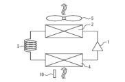
- FIG. 1 is a schematic diagram showing the configuration of a refrigeration cycle device according to Embodiment 1.
- FIG. FIG. 2 is a block diagram showing a control system of the refrigeration cycle device according to the first embodiment.
- FIG. 3 is a diagram illustrating the operation of the refrigeration cycle device according to the first embodiment. 3 is a control flowchart of the refrigeration cycle device according to Embodiment 1.
- FIG. FIG. 2 is a Mollier diagram of the refrigeration cycle device according to the first embodiment. It is a figure explaining operation of the refrigeration cycle device concerning the 1st modification of Embodiment 1. It is a control flowchart of the refrigeration cycle apparatus based on the 1st modification of Embodiment 1.
- FIG. 7 is a diagram illustrating the operation of the refrigeration cycle device according to a second modification of the first embodiment.
- FIG. 7 is a diagram illustrating the operation of the refrigeration cycle device according to a second modification of the first embodiment. It is a control flowchart of the refrigeration cycle apparatus based on the 2nd modification of Embodiment 1. 3 is a diagram showing an example of a configuration for realizing the functions of a control device in Embodiment 1.
- FIG. 7 is a diagram illustrating the operation of the refrigeration cycle device according to a second modification of the first embodiment. It is a control flowchart of the refrigeration cycle apparatus based on the 2nd modification of Embodiment 1. 3 is a diagram showing an example of a configuration for realizing the functions of a control device in Embodiment 1.
- FIG. 1 is a schematic diagram showing the configuration of a refrigeration cycle device according to Embodiment 1.
- FIG. 2 is a block diagram showing a control system of the refrigeration cycle device according to the first embodiment.
- the refrigeration cycle device includes a refrigerant circuit in which refrigerant circulates.
- the refrigerant circuit is comprised of a compressor 1, a condenser 2, an evaporator 4, and a pressure reducing device 3, as shown in FIG.
- the compressor 1 functions as a means for compressing refrigerant in a refrigerant circuit.
- refrigerant circuit there are inverter type compressors and constant speed type compressors, and the compressor 1 in the present disclosure is a constant speed type.
- the condenser 2 and the evaporator 4 are heat exchangers that exchange heat between the refrigerant circulating in the refrigerant circuit and air.
- the refrigeration cycle device includes a blower fan 5 as means for sending air to the condenser 2 and the evaporator 4.
- a blower fan 5 may be provided.
- the refrigeration cycle device may include a blower fan corresponding to each of the condenser 2 and the evaporator 4.
- the pressure reducing device 3 applies a pressure drop to the refrigerant circulating in the refrigerant circuit, and functions as a means for ensuring the degree of subcooling and superheating in the refrigeration cycle.
- a capillary tube with a fixed Cv value or an electronic expansion valve with a variable Cv value can be used as the pressure reducing device 3.
- the condenser 2 condenses the high-pressure refrigerant compressed by the compressor 1.
- the pressure reducing device 3 reduces and expands the high pressure refrigerant that has passed through the condenser 2.
- the evaporator 4 evaporates the low-pressure refrigerant whose pressure has been reduced by the pressure reducing device 3 .
- the refrigeration cycle device according to this embodiment may be used for the purpose of heating air with the condenser 2, or may be used for the purpose of cooling the air with the evaporator 4.
- the refrigeration cycle device according to this embodiment can be used, for example, in an air conditioner, a dehumidifier, a refrigerator, or the like.
- the refrigeration cycle device includes a control device 6 as a control means for controlling device operation.
- the control device 6 controls the operation of the blower fan 5 .
- the control device 6 may also control the operation of the compressor 1, as shown in FIG.
- FIG. 3 is a diagram illustrating the operation of the refrigeration cycle device according to the first embodiment.
- FIG. 4 is a control flowchart of the refrigeration cycle device according to the first embodiment.
- the horizontal axis indicates the elapsed time from the start of product operation.
- the vertical axis indicates the rotation speed of the blower fan 5 and the operating state of the compressor 1.
- the control device 6 sets the rotation speed of the blower fan 5 to a second rotation speed lower than the first rotation speed, which is a reference setting value. Then, the blower fan 5 starts operating (step S002). The operation of the blower fan 5 at the second rotation speed is continued until a specified time X minutes have elapsed from the start of operation (step S003), and after the specified time X minutes have elapsed, the rotation speed of the blower fan 5 is changed to the second rotation speed. The rotation speed is changed from the reference setting value to the first rotation speed, and the blower fan 5 is brought into a normal operating state (step S004).
- FIG. 5 is a Mollier diagram of the refrigeration cycle device according to the first embodiment. The effect of operating the blower fan 5 at the second rotation speed lower than the first rotation speed described above will be explained with reference to FIG. 5 and mathematical expressions. Formulas representing the refrigeration cycle are collectively shown in the following formulas (1), (2), and (3) using the symbols shown in FIG.
- the compressor suction pressure decreases, and the compressor suction refrigerant density decreases.
- the compressor suction refrigerant density decreases, leading to a decrease in the compressor adiabatic efficiency ⁇ c.
- the second rotation speed is set as a rotation speed relatively lower than the first rotation speed, which is a reference setting value set as the rotation speed of the blower fan 5 during normal operation.
- the second rotation speed be set as a rotation speed within a range of 70% to 80% of the first rotation speed.
- control is performed to set the rotational speed of the blower fan 5 to the second rotational speed as a means for ensuring compressor discharge superheat.
- the refrigeration cycle enters a transient state, and it takes time to ensure compressor discharge superheat. Therefore, the operating time of the blower fan 5 at the second rotation speed is set as a specified time of X minutes.
- the specified time X minutes cannot be specified as a single value because it is affected by the state of the refrigeration cycle, the amount of refrigerant enclosed, the amount of refrigerating machine oil, etc., but as an example, the specified time X minutes is 10 minutes to 20 minutes. It is desirable to set the time within the range.
- the refrigeration cycle device may include an ambient temperature detection section 10, as shown in FIGS. 1 and 2.
- the ambient temperature detection unit 10 detects the dry bulb temperature of the air sucked in by the blower fan 5.
- the control for changing the rotation speed of the blower fan 5 may be determined whether the control for changing the rotation speed of the blower fan 5 is enabled based on the temperature detected by the ambient temperature detection unit 10. For example, when the temperature detected by the ambient temperature detection unit 10 is lower than a threshold value, control may be performed to set the rotation speed of the blower fan 5 to the second rotation speed.
- FIG. 6 is a diagram illustrating the operation of the refrigeration cycle device according to the first modification of the first embodiment.
- FIG. 7 is a control flowchart of the refrigeration cycle device according to the first modification of the first embodiment.
- the horizontal axis indicates the elapsed time from the start of product operation.
- the vertical axis indicates the rotation speed of the blower fan 5 and the operating state of the compressor 1.
- the control device 6 sets the blower fan 5 to a first rotation speed that is a reference setting value.
- the operation of the ventilation fan 5 is started (step S102).
- the operation of the blower fan 5 at the first rotation speed, which is the reference setting value, is continued until a specified time Y minutes has elapsed from the start of operation (step S103).
- the prescribed time Y minutes is set as a time shorter than the prescribed time X minutes, as shown in FIG.
- step S104 it is determined whether a specified time X minutes have passed since the start of operation. If the specified time X minutes have not elapsed since the start of operation, it is determined whether the current rotation speed of the blower fan 5 is equal to or higher than the second rotation speed (step S105). In step S105, if the current rotational speed of the blower fan 5 is equal to or higher than the second rotational speed, the rotational speed of the ventilation fan 5 is set to the second rotational speed (step S106), and the air is blown at the second rotational speed. The operation of the fan 5 is maintained until a specified time of X minutes has elapsed from the start of operation. In step S105, if the current number of rotations of the blower fan 5 is less than the second number of rotations, the control for changing the number of rotations of the blower fan 5 is ended, and the process shifts to normal operation (step S107).
- step S108 it is determined whether the current rotation speed of the blower fan 5 is less than the reference setting value. If the current rotational speed of the blower fan 5 is less than the reference setting value, the rotational speed of the ventilation fan 5 is changed to the reference setting value (step S109), and the process shifts to normal operation (step S107). In step S108, if the current rotation speed of the blower fan 5 is equal to or higher than the reference setting value, the control for changing the rotation speed of the blower fan 5 is ended and normal operation is started (step S107).
- the rotation speed of the blower fan 5 is set as the reference setting value instead of the second rotation speed, and after a specified time Y minutes, Changed to 2nd rotation speed.
- the purpose of the control of this first modification is to avoid the risk that a user may have doubts about a product in which the blower fan 5 starts operating at a second rotation speed that is not the reference setting value.
- FIGS. 8 and 9 are diagrams explaining the operation of the refrigeration cycle device according to the second modification of the first embodiment.
- FIG. 10 is a control flowchart of the refrigeration cycle device according to the second modification of the first embodiment.
- the horizontal axis indicates the elapsed time from the start of product operation.
- the vertical axis indicates the rotation speed of the blower fan 5 and the operating state of the compressor 1.
- step S201 when the compressor 1 and the blower fan 5 operate at the start of product operation (step S201), the control device 6 sets the blower fan 5 to the first rotation speed, which is the reference setting value.
- the operation of the blower fan 5 is started (step S202).
- the operation of the blower fan 5 at the first rotation speed, which is the reference setting value, is continued until a specified time Y minutes has elapsed from the start of operation (step S203).
- step S204 it is determined whether a specified time X minutes have passed since the start of operation. If the specified time X minutes have not elapsed since the start of operation, it is determined whether the current rotation speed of the blower fan 5 is equal to or higher than the second rotation speed (step S205). In step S205, if the current rotation speed of the blower fan 5 is equal to or higher than the second rotation speed, the rotation speed of the blower fan 5 is lowered by ⁇ R (step S206). After the rotational speed of the blower fan 5 is lowered by ⁇ R, if the prescribed time Z minutes have passed (step S207), the process returns to step S204. In step S205, if the current number of rotations of the blower fan 5 is less than the second number of rotations, the control for changing the number of rotations of the blower fan 5 is ended, and the process shifts to normal operation (step S208).
- step S209 it is determined whether the current rotation speed of the blower fan 5 is less than the reference setting value. If the current rotational speed of the ventilation fan 5 is less than the reference setting value, the rotational speed of the ventilation fan 5 is increased by ⁇ R (step S210). After increasing the rotational speed of the blower fan 5 by ⁇ R, if a prescribed time period Z has elapsed (step S211), the process returns to step S209. In step S209, if the current rotation speed of the blower fan 5 is equal to or higher than the reference setting value, the control for changing the rotation speed of the blower fan 5 is ended and the process shifts to normal operation (step S208).
- the rotation speed of the blower fan 5 when changing the rotation speed of the blower fan 5 according to the determination results in step S205 and step S209, the rotation speed is not changed to an absolute value, but is changed relatively. change.
- the second modification by reducing the range of change in the rotation speed of the blower fan 5, it is possible to reduce the time that the refrigeration cycle is in a transient state and to suppress the risk of refrigeration oil coming out from the compressor 1. can.
- FIG. 11 is a diagram showing an example of a configuration for realizing the functions of the control device 6 in the first embodiment.
- the functions of the control device 6 are realized, for example, by a processing circuit.
- the processing circuitry may be dedicated hardware 140.
- the processing circuit may include a processor 141 and a memory 142. Part of the processing circuitry may be formed as dedicated hardware 140 and may further include a processor 141 and a memory 142 . In the example shown in FIG. 11, part of the processing circuitry is formed as dedicated hardware 140.
- the processing circuit further includes a processor 141 and a memory 142.
- Processing circuitry may include, for example, a single circuit, a composite circuit, a programmed processor, a parallel programmed processor, an ASIC, an FPGA, or a combination thereof. .
- the processing circuit includes at least one processor 141 and at least one memory 142
- the functions of the control device 6 are realized by software, firmware, or a combination of software and firmware.
- the processor 141 reads and executes programs stored in the memory 142 to realize the functions of each section.
- the processor 141 is also referred to as a CPU (Central Processing Unit), central processing unit, processing unit, arithmetic unit, microprocessor, microcomputer, or DSP.
- Examples of the memory 142 include nonvolatile or volatile semiconductor memories such as RAM, ROM, flash memory, EPROM, and EEPROM, or magnetic disks, flexible disks, optical disks, compact disks, minidisks, and DVDs.
- the processing circuit can realize the functions of the control device 6 using hardware, software, firmware, or a combination thereof.
- the refrigeration cycle device can be used, for example, in devices such as air conditioners, dehumidifiers, and refrigerators.
Landscapes
- Engineering & Computer Science (AREA)
- Physics & Mathematics (AREA)
- Mechanical Engineering (AREA)
- Thermal Sciences (AREA)
- General Engineering & Computer Science (AREA)
- Air Conditioning Control Device (AREA)
- Devices That Are Associated With Refrigeration Equipment (AREA)
Abstract
冷凍サイクル装置は、一定速式の圧縮機、凝縮器、蒸発器および減圧装置から構成される冷媒回路と、前記蒸発器および前記凝縮器に風を送る送風ファンと、前記送風ファンを制御する制御手段と、を備えるものである。製品運転開始時に前記圧縮機および前記送風ファンが稼働する際、前記制御手段は、前記送風ファンの回転数を基準設定値である第1回転数より低い第2回転数に設定して前記送風ファンの運転を開始させて、前記第2回転数での前記送風ファンの運転を規定時間が経過するまで継続させ、前記規定時間の経過後に前記送風ファンの回転数を前記第2回転数から前記第1回転数に変更して前記送風ファンを運転させる。
Description
本開示は、冷凍サイクル装置に関するものである。
エアコン、冷蔵庫および除湿機などに用いられる冷凍サイクルにおいては、製品が運転している最中は圧縮機内に冷凍機油を維持することで圧縮機の軸かじりを回避している。特に、製品の運転開始直後においては、冷媒のスーパーヒートが確保できないサイクル状態になることで、圧縮機内に冷凍機油が枯渇するリスクが高まる。特許文献1には、冷媒流量を推定し、予め設定した閾値より高い場合には、圧縮機の運転周波数を下げて吐出される冷凍機油の量を抑え、圧縮機内の冷凍機油枯渇を防ぐ技術が開示されている。
特許文献1に開示される技術は、インバータ式の圧縮機には適用することができるが、一定速式の圧縮機には適用することができない技術である。
本開示は、上記のような課題を解決するためのものである。本開示の目的は、一定速式の圧縮機を備える冷凍サイクル装置において、圧縮機内の冷凍機油が枯渇することを防いで圧縮機の軸かじりを回避することである。
本開示に係る冷凍サイクル装置は、一定速式の圧縮機、凝縮器、蒸発器および減圧装置から構成される冷媒回路と、前記蒸発器および前記凝縮器に風を送る送風ファンと、前記送風ファンを制御する制御手段と、を備えるものである。製品運転開始時に前記圧縮機および前記送風ファンが稼働する際、前記制御手段は、前記送風ファンの回転数を基準設定値である第1回転数より低い第2回転数に設定して前記送風ファンの運転を開始させて、前記第2回転数での前記送風ファンの運転を規定時間が経過するまで継続させ、前記規定時間の経過後に前記送風ファンの回転数を前記第2回転数から前記第1回転数に変更して前記送風ファンを運転させる。
本開示によれば、一定速式の圧縮機を備える冷凍サイクル装置において、圧縮機内の冷凍機油が枯渇することを防いで圧縮機の軸かじりを回避することができる。
以下、添付の図面を参照して、実施の形態について説明する。各図における同一の符号は、同一の部分または相当する部分を示す。また、本開示では、重複する説明については適宜に簡略化または省略する。なお、本開示は、以下の実施の形態で説明する構成のうち、組み合わせ可能な構成のあらゆる組み合わせを含み得るものである。
実施の形態1.
図1は、実施の形態1に係る冷凍サイクル装置の構成を示す模式図である。図2は、実施の形態1に係る冷凍サイクル装置の制御系統を示すブロック図である。
図1は、実施の形態1に係る冷凍サイクル装置の構成を示す模式図である。図2は、実施の形態1に係る冷凍サイクル装置の制御系統を示すブロック図である。
本実施の形態に係る冷凍サイクル装置は、冷媒が循環する冷媒回路を備える。冷媒回路は、図1に示すように、圧縮機1、凝縮器2、蒸発器4および減圧装置3から構成される。
圧縮機1は、冷媒回路において冷媒を圧縮する手段として機能する。一般的に、圧縮機にはインバータ式のものと一定速式のものとが存在するが、本開示における圧縮機1は、一定速式のものである。
凝縮器2および蒸発器4は、冷媒回路を循環する冷媒と空気との間での熱交換を行う熱交換器である。本実施の形態に係る冷凍サイクル装置は、図1に示すように、凝縮器2および蒸発器4に風を送る手段として、送風ファン5を備えている。なお、図1では送風ファン5を1つのみ図示しているが、複数の送風ファン5が備えられていてもよい。冷凍サイクル装置は、凝縮器2および蒸発器4のそれぞれに対応する送風ファンを備えていてもよい。
減圧装置3は、冷媒回路を循環する冷媒に対して圧損を加えるものであり、冷凍サイクルにおける過冷却度(サブクール)および過熱度(スーパーヒート)を確保するための手段として機能する。減圧装置3としては、例えば、Cv値が固定されているキャピラリーチューブあるいはCv値を可変できる電子膨張弁等を用いることができる。
凝縮器2は、圧縮機1により圧縮された高圧冷媒を凝縮させる。減圧装置3は、凝縮器2を通過した高圧冷媒を減圧および膨張させる。蒸発器4は、減圧装置3により減圧された低圧冷媒を蒸発させる。本実施の形態に係る冷凍サイクル装置は、凝縮器2によって空気を加熱する目的で使用されてもよいし、蒸発器4によって空気を冷却する目的で使用されてもよい。本実施の形態に係る冷凍サイクル装置は、例えば、空気調和機、除湿機あるいは冷蔵庫等において利用することができる。
図2に示すように、本実施の形態に係る冷凍サイクル装置は、機器動作を制御する制御手段として、制御装置6を備える。制御装置6は、送風ファン5の動作を制御する。なお、制御装置6は、図2に示すように、圧縮機1の動作も制御してもよい。
図3は、実施の形態1に係る冷凍サイクル装置の動作を説明する図である。図4は、実施の形態1に係る冷凍サイクル装置の制御フローチャートである。図3において、横軸は、製品運転開始からの経過時間を示している。また、図3において、縦軸は、送風ファン5の回転数および圧縮機1の動作状態を示している。図3および図4を参照し、本実施の形態に係る冷凍サイクル装置の動作の特徴について説明する。
製品運転開始時(ステップS001)に圧縮機1および送風ファン5が稼働する際、制御装置6は、送風ファン5の回転数を基準設定値である第1回転数より低い第2回転数に設定して送風ファン5の運転を開始させる(ステップS002)。この第2回転数での送風ファン5の運転を、運転開始から規定時間X分が経過するまで継続させ(ステップS003)、規定時間X分の経過後に送風ファン5の回転数を第2回転数から基準設定値である第1回転数に変更して、送風ファン5を通常運転の状態へ移行させる(ステップS004)。
図5は、実施の形態1に係る冷凍サイクル装置のモリエル線図である。図5および数式を参照し、上述した第1回転数より低い第2回転数で送風ファン5を運転させることの効果について説明する。図5中に記載の記号を用いて、冷凍サイクルを示す式を、次式(1)(2)(3)にまとめて示す。
上式(1)(2)(3)は、次式(4)に形に変換することができる。
式(4)より、圧縮機断熱効率ηcが大きくなると、圧縮機吐出エンタルピーh1’は小さくなることが確認できる。逆に、圧縮機断熱効率ηcが小さくなると、圧縮機吐出エンタルピーh1’は大きくなる。圧縮機吐出エンタルピーh1’が大きくなると、圧縮機吐出スーパーヒートが増加し、圧縮機1から出ていく冷凍機油量が低下する。
送風ファン5によって蒸発器4へ供給される空気の風量が低下することで、圧縮機吸入圧力が低下し、圧縮機吸入冷媒密度が低下する。圧縮機吸入冷媒密度が低下することで、圧縮機吸入エントロピーが低下し、圧縮機断熱効率ηcの低下に繋がる。送風ファン5の回転数を下げることで送風ファン5の風量を低下させ、圧縮機吐出エンタルピーh1’を増加させ、また、圧縮機吐出スーパーヒートを増加させることで圧縮機1から出ていく冷凍機油量を低下させることができる。
上述したの通り、本実施の形態によれば、送風ファン5の回転数を低下させることで、圧縮機吐出スーパーヒートを確保するために必要な時間を削減し、圧縮機1内の冷凍機油が枯渇することを防止することができる。本実施の形態によれば、送風ファン5の制御を行うことで、部品追加することなく、一定速式の圧縮機1における軸かじりを回避することができる。
第2回転数は、送風ファン5の通常運転時の回転数として設定された基準設定値である第1回転数よりも相対的に低い回転数として設定される。例えば、第2回転数は、第1回転数に対して70%から80%の範囲内の回転数として設定されることが望ましい。
上述の通り、本実施の形態では、圧縮機吐出スーパーヒートを確保する為の手段として、送風ファン5の回転数を第2回転数に設定する制御を行う。送風ファン5の回転数を変更することで、冷凍サイクルが過渡状態となり、圧縮機吐出スーパーヒートを確保するまで時間を要する。そこで、第2回転数での送風ファン5の運転時間を、規定時間X分として設定される。規定時間X分は、冷凍サイクルの状態、封入冷媒量、封入冷凍機油量等に影響される為、1つの値として特定することはできないが、一例として、規定時間X分は10分から20分の範囲内の時間として設定されることが望ましい。
また、本実施の形態に係る冷凍サイクル装置は、図1および図2に示すように、周囲温度検出部10を備えていても良い。周囲温度検出部10は、送風ファン5により吸い込んだ空気の乾球温度を検出する。
圧縮機1から冷凍機油が出ていくリスクは、周囲温度が低いほど高くなる。これは、冷凍サイクルにおいては、周囲温度が低いほど圧縮機1および各熱交換器に冷媒が液相状態で溜まりやすくなる傾向にあるからである。運転開始時に液相状態の冷媒が循環することで、冷凍機油が圧縮機1から出ていきやすい状態となってしまう。そこで、本実施の形態においては、周囲温度検出部10が検出した温度によって、送風ファン5の回転数を変更する制御を有効とするかの判定を行ってもよい。例えば、周囲温度検出部10が検出した温度が閾値より低い場合に、送風ファン5の回転数を第2回転数とする制御を行ってもよい。
また、図6は、実施の形態1の第1変形例に係る冷凍サイクル装置の動作を説明する図である。図7は、実施の形態1の第1変形例に係る冷凍サイクル装置の制御フローチャートである。図6において、横軸は、製品運転開始からの経過時間を示している。図6において、縦軸は、送風ファン5の回転数および圧縮機1の動作状態を示している。図6および図7を参照し、本実施の形態に係る冷凍サイクル装置の第1変形例について説明する。
この第1変形例では、製品運転開始時(ステップS101)に圧縮機1および送風ファン5が稼働する際、制御装置6は、送風ファン5の基準設定値である第1回転数に設定して送風ファン5の運転を開始させる(ステップS102)。基準設定値である第1回転数での送風ファン5の運転を、運転開始から規定時間Y分が経過するまで継続させる(ステップS103)。規定時間Y分は、図6に示すように、規定時間X分より短い時間として設定される。
ステップS103の処理の後、運転開始から規定時間X分が経過したか判定する(ステップS104)。運転開始から規定時間X分経過していない場合は、現在の送風ファン5の回転数が第2回転数以上となっているか判定する(ステップS105)。ステップS105において、現在の送風ファン5の回転数が第2回転数以上である場合には、送風ファン5の回転数を第2回転数に設定し(ステップS106)、第2回転数での送風ファン5の運転が運転開始から規定時間X分経過するまで維持される。ステップS105において、現在の送風ファン5の回転数が第2回転数未満である場合には、送風ファン5の回転数を変更する制御を終了して通常運転へ移行する(ステップS107)。
運転開始から規定時間X分が経過した場合には、現在の送風ファン5の回転数が基準設定値未満となっているか判定する(ステップS108)。現在の送風ファン5の回転数が基準設定値未満である場合には、送風ファン5の回転数を基準設定値へ変更し(ステップS109)、通常運転へ移行する(ステップS107)。ステップS108において、現在の送風ファン5の回転数が基準設定値以上である場合には、送風ファン5の回転数を変更する制御を終了して通常運転へ移行する(ステップS107)。
このように、第1変形例では、製品運転開始時に圧縮機1と送風ファン5とを稼働する際、送風ファン5の回転数を第2回転数でなく基準設定値として、規定時間Y分後に第2回転数へ変更している。この第1変形例の制御は、基準設定値ではない第2回転数にて送風ファン5が運転を開始した製品に対してユーザーが疑念を抱くリスクを回避することを目的としている。
また、図8および図9は、実施の形態1の第2変形例に係る冷凍サイクル装置の動作を説明する図である。図10は、実施の形態1の第2変形例に係る冷凍サイクル装置の制御フローチャートである。図8および図9において、横軸は、製品運転開始からの経過時間を示している。図8および図9において、縦軸は、送風ファン5の回転数および圧縮機1の動作状態を示している。図8、図9および図10を参照し、本実施の形態に係る冷凍サイクル装置の第2変形例について説明する。
この第2変形例では、製品運転開始時(ステップS201)に圧縮機1および送風ファン5が稼働する際、制御装置6は、送風ファン5の基準設定値である第1回転数に設定して送風ファン5の運転を開始させる(ステップS202)。基準設定値である第1回転数での送風ファン5の運転を、運転開始から規定時間Y分が経過するまで継続させる(ステップS203)。
ステップS203の処理の後、運転開始から規定時間X分が経過したか判定する(ステップS204)。運転開始から規定時間X分経過していない場合は、現在の送風ファン5の回転数が第2回転数以上となっているか判定する(ステップS205)。ステップS205において、現在の送風ファン5の回転数が第2回転数以上である場合には、送風ファン5の回転数をΔR下げる(ステップS206)。送風ファン5の回転数をΔR下げた後、規定時間Z分経過した場合には(ステップS207)、ステップS204の処理へ戻る。ステップS205において、現在の送風ファン5の回転数が第2回転数未満である場合には、送風ファン5の回転数を変更する制御を終了して通常運転へ移行する(ステップS208)。
運転開始から規定時間X分が経過した場合には、現在の送風ファン5の回転数が基準設定値未満となっているか判定する(ステップS209)。現在の送風ファン5の回転数が基準設定値未満である場合には、送風ファン5の回転数をΔR上げる(ステップS210)。送風ファン5の回転数をΔR上げた後、規定時間Z分経過した場合には(ステップS211)、ステップS209の処理へ戻る。ステップS209において、現在の送風ファン5の回転数が基準設定値以上である場合には、送風ファン5の回転数を変更する制御を終了して通常運転へ移行する(ステップS208)。
このように、第2変形例では、ステップS205およびステップS209の判定結果に応じて送風ファン5の回転数を変更する場合に、回転数の絶対値への変更ではなく、回転数を相対的に変更する。第2変形例によれば、送風ファン5の回転数の変化幅を小さくすることで、冷凍サイクルが過渡状態でいる時間を削減し、圧縮機1から冷凍機油が出ていくリスクを抑えることができる。
図11は、実施の形態1における制御装置6の機能を実現する構成の一例を示す図である。制御装置6の機能は、例えば、処理回路により実現される。処理回路は、専用ハードウェア140であってもよい。処理回路は、プロセッサ141およびメモリ142を備えていてもよい。処理回路の一部が専用ハードウェア140として形成され、且つ、当該処理回路は更にプロセッサ141およびメモリ142を備えていてもよい。図11に示す例において、処理回路の一部は専用ハードウェア140として形成されている。また、図4に示す例において、処理回路は、プロセッサ141およびメモリ142を更に備えている。
一部が少なくとも1つの専用ハードウェア140である処理回路には、例えば、単一回路、複合回路、プログラム化したプロセッサ、並列プログラム化したプロセッサ、ASIC、FPGA、またはこれらを組み合わせたものが該当する。
処理回路が少なくとも1つのプロセッサ141および少なくとも1つのメモリ142を備える場合、制御装置6の機能は、ソフトウェア、ファームウェア、またはソフトウェアとファームウェアとの組み合わせにより実現される。
ソフトウェアおよびファームウェアはプログラムとして記述され、メモリ142に格納される。プロセッサ141は、メモリ142に記憶されたプログラムを読み出して実行することにより、各部の機能を実現する。プロセッサ141は、CPU(Central Processing Unit)、中央処理装置、処理装置、演算装置、マイクロプロセッサ、マイクロコンピュータあるいはDSPともいう。メモリ142には、例えば、RAM、ROM、フラッシュメモリー、EPROMおよびEEPROM等の不揮発性または揮発性の半導体メモリ、または磁気ディスク、フレキシブルディスク、光ディスク、コンパクトディスク、ミニディスクおよびDVD等が該当する。
このように、処理回路は、ハードウェア、ソフトウェア、ファームウェア、またはこれらの組み合わせによって、制御装置6の機能を実現することができる。
本開示に係る冷凍サイクル装置は、例えば、空気調和機、除湿機および冷蔵庫等の機器に利用することができる。
1 圧縮機、 2 凝縮器、 3 減圧装置、 4 蒸発器、 5 送風ファン、 6 制御装置、 10 周囲温度検出部、 140 専用ハードウェア、 141 プロセッサ、 142 メモリ
Claims (3)
- 一定速式の圧縮機、凝縮器、蒸発器および減圧装置から構成される冷媒回路と、
前記蒸発器および前記凝縮器に風を送る送風ファンと、
前記送風ファンを制御する制御手段と、
を備え、
製品運転開始時に前記圧縮機および前記送風ファンが稼働する際、前記制御手段は、前記送風ファンの回転数を基準設定値である第1回転数より低い第2回転数に設定して前記送風ファンの運転を開始させて、前記第2回転数での前記送風ファンの運転を規定時間が経過するまで継続させ、前記規定時間の経過後に前記送風ファンの回転数を前記第2回転数から前記第1回転数に変更して前記送風ファンを運転させる冷凍サイクル装置。 - 前記第2回転数は、前記第1回転数に対して70%から80%の範囲内の回転数として設定されることを特徴とする請求項1に記載の冷凍サイクル装置。
- 前記規定時間は、10分から20分の範囲内の時間として設定されることを特徴とする請求項1または請求項2に記載の冷凍サイクル装置。
Priority Applications (2)
| Application Number | Priority Date | Filing Date | Title |
|---|---|---|---|
| JP2024522802A JPWO2023228323A1 (ja) | 2022-05-25 | 2022-05-25 | |
| PCT/JP2022/021415 WO2023228323A1 (ja) | 2022-05-25 | 2022-05-25 | 冷凍サイクル装置 |
Applications Claiming Priority (1)
| Application Number | Priority Date | Filing Date | Title |
|---|---|---|---|
| PCT/JP2022/021415 WO2023228323A1 (ja) | 2022-05-25 | 2022-05-25 | 冷凍サイクル装置 |
Publications (1)
| Publication Number | Publication Date |
|---|---|
| WO2023228323A1 true WO2023228323A1 (ja) | 2023-11-30 |
Family
ID=88918701
Family Applications (1)
| Application Number | Title | Priority Date | Filing Date |
|---|---|---|---|
| PCT/JP2022/021415 WO2023228323A1 (ja) | 2022-05-25 | 2022-05-25 | 冷凍サイクル装置 |
Country Status (2)
| Country | Link |
|---|---|
| JP (1) | JPWO2023228323A1 (ja) |
| WO (1) | WO2023228323A1 (ja) |
Citations (8)
| Publication number | Priority date | Publication date | Assignee | Title |
|---|---|---|---|---|
| JPH01169261A (ja) * | 1987-12-25 | 1989-07-04 | Hitachi Ltd | ヒートポンプ式空気調和機 |
| JP2002257427A (ja) * | 2001-02-28 | 2002-09-11 | Mitsubishi Electric Corp | 冷凍空調装置、及びその運転方法 |
| JP2013053817A (ja) * | 2011-09-05 | 2013-03-21 | Panasonic Corp | 物品冷却装置とそれを備えた自動販売機 |
| US20150330688A1 (en) * | 2014-05-16 | 2015-11-19 | Lennox Industries Inc. | Compressor operation management in air conditioners |
| JP2016050752A (ja) * | 2014-09-02 | 2016-04-11 | 株式会社デンソー | エジェクタ式冷凍サイクル装置 |
| WO2017085886A1 (ja) * | 2015-11-20 | 2017-05-26 | 三菱電機株式会社 | 冷凍サイクル装置及び冷凍サイクル装置の制御方法 |
| JP2020200958A (ja) * | 2019-06-06 | 2020-12-17 | シャープ株式会社 | 空気調和機 |
| WO2022059149A1 (ja) * | 2020-09-17 | 2022-03-24 | 三菱電機株式会社 | 冷凍サイクル装置及びそれを備える空気調和機、並びに冷凍サイクル装置の制御方法 |
-
2022
- 2022-05-25 JP JP2024522802A patent/JPWO2023228323A1/ja active Pending
- 2022-05-25 WO PCT/JP2022/021415 patent/WO2023228323A1/ja unknown
Patent Citations (8)
| Publication number | Priority date | Publication date | Assignee | Title |
|---|---|---|---|---|
| JPH01169261A (ja) * | 1987-12-25 | 1989-07-04 | Hitachi Ltd | ヒートポンプ式空気調和機 |
| JP2002257427A (ja) * | 2001-02-28 | 2002-09-11 | Mitsubishi Electric Corp | 冷凍空調装置、及びその運転方法 |
| JP2013053817A (ja) * | 2011-09-05 | 2013-03-21 | Panasonic Corp | 物品冷却装置とそれを備えた自動販売機 |
| US20150330688A1 (en) * | 2014-05-16 | 2015-11-19 | Lennox Industries Inc. | Compressor operation management in air conditioners |
| JP2016050752A (ja) * | 2014-09-02 | 2016-04-11 | 株式会社デンソー | エジェクタ式冷凍サイクル装置 |
| WO2017085886A1 (ja) * | 2015-11-20 | 2017-05-26 | 三菱電機株式会社 | 冷凍サイクル装置及び冷凍サイクル装置の制御方法 |
| JP2020200958A (ja) * | 2019-06-06 | 2020-12-17 | シャープ株式会社 | 空気調和機 |
| WO2022059149A1 (ja) * | 2020-09-17 | 2022-03-24 | 三菱電機株式会社 | 冷凍サイクル装置及びそれを備える空気調和機、並びに冷凍サイクル装置の制御方法 |
Also Published As
| Publication number | Publication date |
|---|---|
| JPWO2023228323A1 (ja) | 2023-11-30 |
Similar Documents
| Publication | Publication Date | Title |
|---|---|---|
| JP4711020B2 (ja) | 空気調和装置 | |
| JP6847299B2 (ja) | 冷凍サイクル装置 | |
| JP6559333B2 (ja) | 空気調和機 | |
| EP2270405A1 (en) | Refrigerating device | |
| JP6004670B2 (ja) | 空気調和装置の制御装置及び空気調和装置の制御方法並びに空気調和装置のプログラム、それを備えた空気調和装置 | |
| JP3835453B2 (ja) | 空気調和装置 | |
| JP5180680B2 (ja) | 冷凍サイクル | |
| JP2018138841A (ja) | 空気調和装置 | |
| JP6495064B2 (ja) | 空調システムの制御装置、空調システム、空調システムの制御プログラム、及び空調システムの制御方法 | |
| JP2016109413A (ja) | 空調機 | |
| JPH10325621A (ja) | 空気調和装置 | |
| JP6576468B2 (ja) | 空気調和機 | |
| JP2004170023A (ja) | 多室形空気調和機の制御方法 | |
| JP6758506B2 (ja) | 空気調和装置 | |
| JP4969271B2 (ja) | 空気調和機 | |
| JP2006194526A (ja) | 空気調和装置 | |
| WO2023228323A1 (ja) | 冷凍サイクル装置 | |
| JPH1096545A (ja) | 空気調和機およびその制御方法 | |
| WO2020003490A1 (ja) | 空気調和装置 | |
| KR101153421B1 (ko) | 에어컨의 응축용량 제어 방법 | |
| JP2007327717A (ja) | 空気調和機 | |
| KR20070088077A (ko) | 공기조화기 및 그 제어방법 | |
| JP6628972B2 (ja) | 空調システムの制御装置、空調システム、空調システムの制御プログラム、及び空調システムの制御方法 | |
| JP2023019957A (ja) | 空気調和機 | |
| US20230131781A1 (en) | Refrigeration cycle apparatus |
Legal Events
| Date | Code | Title | Description |
|---|---|---|---|
| 121 | Ep: the epo has been informed by wipo that ep was designated in this application |
Ref document number: 22943726 Country of ref document: EP Kind code of ref document: A1 |
|
| ENP | Entry into the national phase |
Ref document number: 2024522802 Country of ref document: JP Kind code of ref document: A |