WO2023224032A1 - シート部品 - Google Patents
シート部品 Download PDFInfo
- Publication number
- WO2023224032A1 WO2023224032A1 PCT/JP2023/018249 JP2023018249W WO2023224032A1 WO 2023224032 A1 WO2023224032 A1 WO 2023224032A1 JP 2023018249 W JP2023018249 W JP 2023018249W WO 2023224032 A1 WO2023224032 A1 WO 2023224032A1
- Authority
- WO
- WIPO (PCT)
- Prior art keywords
- frame
- hole
- stopper
- seat
- reinforcing
- Prior art date
- Legal status (The legal status is an assumption and is not a legal conclusion. Google has not performed a legal analysis and makes no representation as to the accuracy of the status listed.)
- Ceased
Links
Images


Classifications
-
- A—HUMAN NECESSITIES
- A47—FURNITURE; DOMESTIC ARTICLES OR APPLIANCES; COFFEE MILLS; SPICE MILLS; SUCTION CLEANERS IN GENERAL
- A47C—CHAIRS; SOFAS; BEDS
- A47C7/00—Parts, details, or accessories of chairs or stools
- A47C7/54—Supports for the arms
-
- B—PERFORMING OPERATIONS; TRANSPORTING
- B60—VEHICLES IN GENERAL
- B60N—SEATS SPECIALLY ADAPTED FOR VEHICLES; VEHICLE PASSENGER ACCOMMODATION NOT OTHERWISE PROVIDED FOR
- B60N2/00—Seats specially adapted for vehicles; Arrangement or mounting of seats in vehicles
- B60N2/75—Arm-rests
-
- B—PERFORMING OPERATIONS; TRANSPORTING
- B68—SADDLERY; UPHOLSTERY
- B68G—METHODS, EQUIPMENT, OR MACHINES FOR USE IN UPHOLSTERING; UPHOLSTERY NOT OTHERWISE PROVIDED FOR
- B68G7/00—Making upholstery
- B68G7/06—Filling of cushions, mattresses, or the like
Definitions
- the present invention relates to a seat component that is rotatably attached to a seat frame.
- an armrest is known as a seat component that is rotatably attached to a seat frame (Patent Document 1).
- the armrest has a frame covered with a skin member, and the interior of the skin member is filled with a cushion member.
- an object of the present invention is to suppress leakage of the cushion member from the through hole of the frame during manufacturing of the seat member.
- the seat component for achieving the above-mentioned purpose is attached to the seat frame so as to be rotatable around a rotation axis extending in the rotation axis direction, and includes a frame, a skin member, a sealing member, and a cushion member.
- the frame constitutes the skeleton of the seat component.
- the frame has a through hole around the rotation axis.
- the skin member covers the frame with the through hole exposed.
- a sealing member is attached to the frame.
- the cushion member fills the space between the frame, the sealing member, and the skin member.
- the sealing member has an annular projection that contacts the frame. The contact portion between the protrusion and the frame surrounds the through hole.
- the sealing member can suppress leakage of the cushion member from the through hole of the sheet member during manufacturing of the sheet member. Therefore, the process of removing the cushion member protruding from the through hole can be eliminated.
- the protrusion of the sealing member may have a shape that tapers toward the tip that contacts the frame.
- the protrusion of the sealing member may have a flexible structure.
- the frame has an inclined surface arranged to surround the through hole of the sealing member and is inclined with respect to a plane perpendicular to the rotation axis, and the protrusion of the sealing member is in contact with the inclined surface.
- a configuration may also be used.
- the sealing member has a cylindrical portion and a flat plate portion extending from the cylindrical portion in the longitudinal direction of the frame, the flat plate portion contacts the frame, and the contact portion between the protrusion and the frame is the flat plate portion.
- the seat frame may be further away from the seat frame than the contact portion between the seat frame and the seat frame.
- the frame further includes a stopper that protrudes toward the seat frame and restricts the range in which the seat component rotates, and a stopper hole formed in the stopper, and the flat plate portion has a rotation axis. It may also be configured to overlap the stopper when viewed along the direction and suppress leakage of the material of the cushion member from between the stopper holes.
- the flat plate portion of the sealing member overlaps with the stopper, it is possible to suppress the material of the cushion member from leaking from the stopper hole.
- the frame includes a main frame and a reinforcing frame, the main frame has a stopper insertion hole, the reinforcing frame has a stopper and a stopper hole, and the stopper has a stopper insertion hole.
- the stopper may be inserted into the stopper insertion hole and protrude toward the seat frame from the stopper insertion hole.
- the stopper projects from the stopper insertion hole toward the seat frame, thereby making it possible to restrict the range in which the seat component rotates.
- the stopper may have a concave portion on the surface facing the flat plate portion, and the flat plate portion may have a convex portion that enters the concave portion.
- the convex part of the flat part enters the concave part of the stopper, thereby positioning the flat part with respect to the stopper.
- the reinforcing frame may be made of a metal plate, and the amount of protrusion of the convex portion may be larger than the thickness of the reinforcing frame.
- the sealing member may have a claw portion that extends from the flat plate portion and engages with the frame, and the claw portion may have a configuration in which the position in the longitudinal direction overlaps with the stopper hole. good.
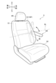
- FIG. 1 is a perspective view of a seat including an armrest according to an embodiment.
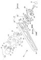
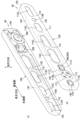
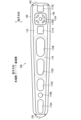
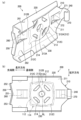
- FIG. 3 is an exploded perspective view of the armrest. They are a perspective view (a) as seen from the left side and a perspective view (b) as seen from the right side of the armrest frame to which the sealing member is attached.
- FIG. 3 is a side view of the main frame.
- FIG. 3 is a side view showing the base end portion of the main frame.
- They are a perspective view (a) and a side view (b) of a reinforcing frame.
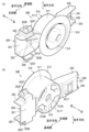
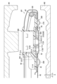
- FIG. 8 is a cross-sectional view (a) of the armrest frame to which the sealing member is attached, corresponding to the YY cross-section of FIG. 7, and (b) a cross-sectional view of the armrest corresponding to the Z-Z cross-section. They are a perspective view (a) of the sealing member seen from the left side and a perspective view (b) of the sealing member seen from the right side.
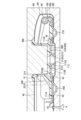
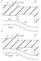
- FIG. 9 is a sectional view corresponding to FIG. 8 of the armrest frame covered with the skin member, the upper mold, and the lower mold in the manufacturing process.
- FIG. 12 is a diagram showing a state in which the skin member and the armrest frame are set in the upper mold and the lower mold from the state shown in FIG. 11 in the manufacturing process.
- front and back, left and right, and up and down are based on front and back, left and right, and up and down as seen from a person sitting on a seat provided with an armrest AR.
- the seat is configured as a vehicle seat S mounted on an automobile, and includes a seat back S1, a seat cushion S2, a headrest HR, and an armrest AR as an example of seat components. ing.
- the vehicle seat S has a built-in seat frame SF that constitutes the skeleton of the seat back S1 and the seat cushion S2.
- the seat back S1 and the seat cushion S2 are constructed by covering the seat frame SF with a pad made of a cushioning material such as urethane foam, and a skin material made of leather, fabric, or the like.
- the seat frame SF includes a side frame S11 that constitutes the left and right frames of the seat back S1, and a bracket 10 fixed to the left side frame S11.
- the armrest AR is arranged on the left side of the seat back S1, and is rotatably attached to the seat frame SF. Specifically, one longitudinal end of the armrest AR is fixed to a shaft 20 (see FIG. 2), and the shaft 20 is rotatably supported by the bracket 10, so that the armrest AR is rotatable relative to the seat frame SF. installed.
- the armrest AR is rotatable between a pulled-out state shown by a solid line with the tip facing forward and a retracted state shown by the imaginary line (two-dot chain line) with the tip facing upward.
- the armrest AR is configured such that, for example, a one-way clutch allows only upward rotation and restricts downward rotation within a predetermined angular range from the pulled out state to the stored state. may be provided.
- the armrest AR includes an armrest frame RF as an example of a frame, an outer skin member 40, a cushion member CU (see FIG. 8), and a sealing member 300.
- the skin member 40 is made of leather, fabric, or the like, and is a member that covers the armrest frame RF.
- the cushion member CU is a foamed resin such as foamed polyurethane, and is filled in the space between the armrest frame RF, the sealing member 300, and the skin member 40 (see FIG. 8).
- the armrest frame RF includes a main frame 100, a reinforcing frame 200, and a spacer 600.
- the main frame 100 is a long frame that constitutes the skeleton of the armrest AR, and is formed by processing a metal plate.
- the right side corresponds to the "seat frame side”
- the left side corresponds to the "side opposite to the seat frame side”.
- the end that is closer to the rotation axis RL of the armrest AR is referred to as the base end
- the end that is farther from the rotation axis RL is referred to as the base end.
- the end is called the tip.
- the proximal end is sometimes referred to as the proximal end
- the distal end is sometimes referred to as the distal end.
- the longitudinal direction of the armrest AR (main frame 100) may be simply referred to as the "longitudinal direction”.
- the direction of the rotation axis of the armrest AR which is a direction parallel to the direction in which the rotation axis RL extends, may be simply referred to as the “rotation axis direction.”
- the rotation axis direction corresponds to the left-right direction.
- the direction perpendicular to the rotational axis direction and the longitudinal direction is referred to as the "lateral direction.”
- the main frame 100 includes a long main base wall 110, a first main side wall 120, a second main side wall 130, a third main side wall 140, and a fourth main side wall 150. It has
- the main base wall 110 is a wall that is rotatably attached to the seat frame SF.
- the first main side wall 120 is a wall that extends to the left from one edge in the transverse direction among the edges of the main base wall 110
- the second main side wall 130 is a wall that extends from one edge of the main base wall 110 to the left side. Among these, it is a wall extending to the left from the edge on the other side in the transverse direction.
- the third main side wall 140 is a wall that extends to the left from the proximal edge of the edge of the main base wall 110
- the fourth main side wall 150 is a wall that extends from the edge of the main base wall 110 to the left side. This is a wall extending to the left from the edge on the tip side.
- the main base wall 110 includes a first wall portion 111, a second wall portion 112, and a connecting wall portion 113.
- the second wall portion 112 and the connecting wall portion 113 are located at the base end of the main base wall 110.
- the first wall portion 111 has a first hole 111A and a second hole 111B. Further, the first wall portion 111 has a fragile portion 111C.
- the first hole 111A is a substantially rectangular hole for passing a first stopper portion 260 (see FIG. 3(b)) of the reinforcing frame 200, which will be described later. It is placed on the tip side.
- the second hole 111B is a substantially rectangular hole for passing a second stopper portion 270 (see FIG. 3(b)) of the reinforcing frame 200, which will be described later. It is located on the opposite side to the first hole 111A.
- the first hole 111A and the second hole 111B are examples of stopper insertion holes.
- the second wall portion 112 and the connecting wall portion 113 (convex portion 114 described later) are provided between the first hole 111A and the second hole 111B in the longitudinal direction.
- the weakened portion 111C is located between the first hole 111A and the plurality of holes 112A and 112B provided in the second wall portion 112, so that the weakened portion 111C is a portion located on both sides of the weakened portion 111C itself in the lateral direction. This is a portion where stress is more likely to be applied compared to the second wall portion 112 and the portions located on both sides of the second wall portion 112 in the lateral direction.
- the second wall portion 112 is a portion that is rotatably attached to the seat frame SF, and is disposed offset to the seat frame SF side in the rotational axis direction, that is, to the right side, with respect to the first wall portion 111. There is.
- the second wall portion 112 has a first bolt hole 112A and a first shaft hole 112B.
- the first bolt hole 112A is a hole through which a bolt 91 (see FIG. 2) for fixing the shaft 20 to the armrest frame RF is inserted, and is formed approximately in the center of the second wall portion 112.
- the first bolt hole 112A is formed in a circular shape centered on the rotation axis RL.
- the first shaft hole 112B is a hole through which an extension portion 21A (see FIG. 2) of the shaft 20 (described later) passes, and a plurality of first shaft holes 112B, specifically four, are formed corresponding to the plurality of extension portions 21A of the shaft 20. has been done.
- the four first shaft holes 112B are each formed in a substantially arc shape when viewed from the direction of the rotation axis, and extend around the first bolt hole 112A on the circumference of a circle centered on the rotation axis RL. are placed side by side.
- the first shaft hole 112B is an example of a through hole around the rotation axis.
- the connecting wall portion 113 is a portion that connects the first wall portion 111 and the second wall portion 112.
- the connecting wall portion 113 has four portions corresponding to the quadrangular second wall portion 112.
- the connection wall 113 includes a first connection wall 113A, a second connection wall 113B, a third connection wall 113C, and a fourth connection wall 113D, and surrounds the second wall 112. It is shaped like a square frame.
- Each of the connection walls 113A to 113D is inclined with respect to the rotation axis direction so that as it approaches the second wall 112, it is located on the right side.
- the second wall portion 112 and the connection wall portion 113 form a convex portion 114 that protrudes to the right side (towards the back of the paper in FIG. 5) with respect to the first wall portion 111.
- the convex portion 114 has a rectangular shape when viewed from the rotation axis direction.
- the main base wall 110 further includes a plurality of through holes 115A to 115E and a central convex portion 116.
- the through holes 115A to 115E are holes formed to reduce the weight of the main frame 100.
- the through holes 115A to 115E are formed in line in this order in the longitudinal direction from the distal end to the proximal end.
- the four through holes 115A, 115C to 115E have a substantially elliptical shape that is long in the longitudinal direction, and the through hole 115B has a substantially circular shape.
- the through holes 115A to 115C are formed at the distal end of the main base wall 110 on the distal side of the central convex portion 116, and the through holes 115D and 115E are formed in the central convex portion 116.
- the central convex portion 116 is a convex portion that protrudes to the left with respect to the first wall portion 111 .
- the central convex portion 116 is formed in a substantially elliptical shape that is elongated in the longitudinal direction near the central portion of the main base wall 110 in the longitudinal direction.
- the reinforcing frame 200 is a frame for reinforcing the main frame 100, and, like the main frame 100, is formed by processing a metal plate. .
- the reinforcing frame 200 is formed from a plate-like member that is thicker than the plate-like member that constitutes the main frame 100 .
- the thickness of the reinforcing frame 200 is approximately 1.5 times the thickness of the main frame 100.
- the reinforcing frame 200 includes a reinforcing base wall 210, a first reinforcing side wall 220, a second reinforcing side wall 230, a third reinforcing side wall 240, a fourth reinforcing side wall 250, a first stopper part 260, and a second stopper part. 270.
- the first stopper section 260 and the second stopper section 270 are examples of stoppers.
- the reinforcing base wall 210 is a wall placed so as to overlap the main base wall 110 of the main frame 100.
- the first reinforcing side wall 220 is a wall that extends to the left from one edge in the transverse direction among the edges of the reinforcing base wall 210
- the second reinforcing side wall 230 is a wall that extends to the left from the edge of the reinforcing base wall 210 on one side in the transverse direction.
- it is a wall extending to the left from the edge on the other side in the transverse direction.
- the third reinforcing side wall 240 is a wall that extends to the left from the edge of the reinforcing base wall 210 that is located on the proximal end side of the armrest AR in the longitudinal direction.
- the reinforcing base wall 210 has a base 211, a second protrusion 212, a second bolt hole 213, and a second shaft hole 214.
- the second protrusion 212 is a protrusion that protrudes from the base 211 in the direction of the rotation axis, specifically, to the left.
- the second convex portion 212 is formed in a substantially circular shape at a position overlapping with the convex portion 114 of the main frame 100 when viewed from the rotation axis direction.
- the second convex portion 212 includes a first portion 212A that is disposed offset to the left with respect to the base 211, a second portion 212B that connects the peripheral edge of the base 211 and the substantially circular first portion 212A, and a protrusion. 212C.
- the second portion 212B is arranged to surround the four second shaft holes 214.
- the second portion 212B is a slope inclined with respect to a plane perpendicular to the rotation axis, and is a portion that is contacted by a protrusion 311T of a sealing member 300, which will be described later.
- the protrusion 212C is provided so as to protrude from the second convex portion 212 in the radial direction of a circle centered on the rotation axis RL when viewed from the rotation axis direction.
- the second bolt hole 213 and the second shaft hole 214 are formed in the first portion 212A of the second convex portion 212.
- the second bolt hole 213 is a hole through which the bolt 91 (see FIG. 2) is inserted, and one second bolt hole 213 is formed approximately in the center of the first portion 212A.
- the first bolt hole 112A is formed in a circular shape centered on the rotation axis RL.
- a flange portion 213A that protrudes to the right side is formed at the peripheral edge of the second bolt hole 213 by burring or the like.
- the second shaft hole 214 is a hole into which the extending portion 21A (see FIG. 2) of the shaft 20 engages, and a plurality of second shaft holes 214, specifically four, are formed corresponding to the plurality of extending portions 21A of the shaft 20. has been done.
- the four second shaft holes 214 are each formed into a substantially trapezoidal shape when viewed from the direction of the rotation axis, and extend around the second bolt hole 213 on the circumference of a circle centered on the rotation axis RL. are placed side by side.
- the fourth reinforcing side wall 250 is a wall that rises to the left from the edge of the reinforcing base wall 210 that is located on the tip end side of the armrest AR in the longitudinal direction.
- the fourth reinforcing side wall 250 has a shape in which a central portion 251 in the transverse direction is located at a position shifted in the longitudinal direction with respect to both end portions 252 and 253 in the transverse direction, when viewed from the rotation axis direction.
- the fourth reinforcing side wall 250 has a substantially V-shape such that the center portion 251 is located at a position shifted toward the proximal end in the longitudinal direction with respect to both end portions 252 and 253 when viewed from the rotation axis direction. It is formed in a curved manner.
- the reinforcing frame 200 is arranged on the left side opposite to the bracket 10 (seat frame SF) with the main frame 100 in between, and is provided so as to overlap the base end of the main frame 100 ( (See also Figure 2). Specifically, the reinforcing frame 200 is provided so that the reinforcing base wall 210 contacts and overlaps the proximal end of the main base wall 110 on the opposite side of the bracket 10 with the main base wall 110 interposed therebetween.
- the first reinforcing side wall 220 is provided to overlap the first main side wall 120 on the inner side of the first main side wall 120 in the transverse direction
- the second reinforcing side wall 230 is provided on the inner side of the second main side wall 130 in the transverse direction. It is provided so as to overlap the second main side wall 130 on the inside of the direction.
- the reinforcing frame 200 is provided with a third reinforcing side wall 240 overlapping the third main side wall 140 on the inside of the third main side wall 140 in the longitudinal direction.
- the main frame 100 and the reinforcing frame 200 are connected to each other at a first connecting portion C1, a second connecting portion C2, and a third connecting portion C3.
- the reinforcing frame 200 and the main frame 100 are connected to each other at the proximal end portions at the distal end side of the rotation axis RL by the first connecting portion C1 and the second connecting portion C2, and Portions closer to the proximal end than the rotation axis RL are connected to each other by a third connecting portion C3.
- the first connecting portion C1 is a portion where a folded portion 121 formed on the first main side wall 120 and a folded portion 221 formed on the first reinforcing side wall 220 overlap.
- the folded part 121 is a part of the end of the first main side wall 120 that is folded back toward the main base wall 110
- the folded part 221 is a part of the end of the first reinforced side wall 220 that is folded back toward the main base wall 110. This is the part that is folded back to the side.
- the second connecting portion C2 is a portion where the folded portion 131 formed on the second main side wall 130 and the folded portion 231 formed on the second reinforcing side wall 230 overlap.
- the folded portion 131 is a portion of the end of the second main side wall 130 that is folded back toward the main base wall 110
- the folded portion 231 is a portion of the end of the second reinforced side wall 230 that is folded back toward the reinforced base wall 210. This is the part that is folded back to the side.
- the first connecting portion C1 and the second connecting portion C2 are provided substantially symmetrically in the transverse direction.
- the third connecting portion C3 is a portion where a folded portion 141 formed on the third main side wall 140 and a folded portion 241 formed on the third reinforcing side wall 240 overlap.
- the folded portion 141 is a portion of the end of the third main side wall 140 that is folded back toward the main base wall 110 side
- the folded portion 241 is a portion that is folded back of the end of the third reinforced side wall 240 toward the reinforced base wall 210. This is the part.
- the first stopper part 260 and the second stopper part 270 provided on the reinforcing frame 200 are parts that come into contact with a part of the seat frame SF to restrict the rotation range of the armrest AR. Specifically, the first stopper section 260 and the second stopper section 270 come into contact with the bracket 10 fixed to the side frame S11 to restrict the rotation range of the armrest AR.
- the first stopper portion 260 has a first recess 261 and a first stopper hole 262.
- the first recess 261 is a recess formed in the first stopper part 260.
- the first stopper hole 262 is a hole formed in the first stopper part 260.
- the first stopper portion 260 is made by cutting two parallel lines in a metal plate and then extruding between the two parallel lines.
- the first recess 262 is a recess created when pushed out between two parallel lines.
- the first stopper hole 262 is a hole created when the object is pushed out between two parallel lines.
- the second stopper portion 270 has a second recess 271 and a second stopper hole 272.
- the second recess 271 is a recess formed in the second stopper part 270.
- the second stopper hole 272 is a hole formed in the second stopper part 270.
- the second stopper portion 270 is made by cutting two parallel lines in a metal plate and then extruding between the two parallel lines.
- the second recess 272 is a recess created when the object is pushed out between two parallel lines.
- the second stopper hole 272 is a hole created when the object is pushed out between two parallel lines. Note that the first stopper hole 262 and the second stopper hole 272 are examples of stopper holes.
- the first stopper portion 260 enters the first hole 111A of the main frame 100 and protrudes from the first hole 111A toward the seat frame SF in the direction of the rotation axis. In other words, the first stopper portion 260 protrudes to the right with respect to the base portion 211 so as to pass through the first hole 111A of the main frame 100.
- the first stopper portion 260 protrudes to the right side of the main base wall 110 of the main frame 100, more specifically, the second wall portion 112, in the rotational axis direction.
- the first stopper portion 260 is disposed between the fourth reinforcing side wall 250 and the rotation axis RL in the longitudinal direction.
- the first stopper portion 260 is arranged between the fourth reinforcing side wall 250 and the second convex portion 212 in the longitudinal direction. Further, the first stopper portion 260 is arranged between the first connecting portion C1 and the second connecting portion C2 in the lateral direction.
- the second stopper portion 270 enters the second hole 111B of the main frame 100 and protrudes from the second hole 111B toward the seat frame SF in the direction of the rotation axis. In other words, the second stopper portion 270 protrudes to the right with respect to the base portion 211 so as to pass through the second hole 111B of the main frame 100.
- the second stopper section 270 like the first stopper section 260, protrudes to the right side of the second wall section 112 in the rotational axis direction.
- the second stopper portion 270 is disposed on the opposite side of the first stopper portion 260 with respect to the rotation axis RL in the longitudinal direction.
- the second stopper portion 270 is disposed between the third reinforcing side wall 240 and the rotation axis RL in the longitudinal direction. Specifically, the second stopper portion 270 is arranged between the third reinforcing side wall 240 and the second convex portion 212 in the longitudinal direction.
- the spacer 600 is provided between the main frame 100 and the reinforcing frame 200.
- Spacer 600 has a ring portion 610 and an extension portion 620.
- Ring portion 610 has a through hole through which bolt 90 passes.
- the extending portion 620 extends from the outer periphery of the ring portion 610 toward between the four convex portions 21A of the shaft 20.
- the bracket 10 is a member that rotatably supports the armrest frame RF (armrest AR), and is formed by processing a metal plate. Bracket 10 is arranged between side frame S11 and armrest frame RF.
- the bracket 10 has a bracket base wall 11 and a bracket side wall 12.
- the bracket side wall 12 is a wall extending to the right from the edge of the bracket base wall 11.
- the bracket 10 is fixed to the side frame S11 by fixing the end of the bracket side wall 12 to the side frame S11 by welding or the like.
- the bracket base wall 11 has a shaft support hole 11A that rotatably supports the shaft 20.
- a flange portion 11B extending along the rotation axis RL is formed at the peripheral edge of the shaft support hole 11A by burring or the like.
- the bracket base wall 11 also includes a first regulating portion 11C that is provided to protrude to the left at a position diagonally below the front of the shaft support hole 11A, and a first restriction portion 11C that is provided to protrude to the left at a position diagonally above the shaft support hole 11A. It has a second regulating portion 11D provided as shown in FIG.
- the first restricting portion 11C and the second restricting portion 11D are arranged to sandwich the shaft support hole 11A when viewed from the rotation axis direction, and each is formed in a substantially arc shape when viewed from the rotation axis direction. has been done.
- the armrest AR is moved from the pulled out state when the first stopper part 260 abuts the upper end of the first restricting part 11C and the second stopper part 270 abuts the lower end of the second restricting part 11D. Also, downward rotation is restricted. Further, the armrest AR is rearward than the stored state when the first stopper part 260 abuts the upper end of the second restrictor 11D of the bracket 10 and the second stopper part 270 abuts the lower end of the first restrictor 11C. Rotation to is regulated.
- the shaft 20 is a cylindrical member made of metal, and has a small diameter portion 21 and a large diameter portion 22 formed to have a slightly larger diameter than the small diameter portion 21.
- the shaft 20 has a small diameter portion 21 rotatably supported by the shaft support hole 11A (flange portion 11B) of the bracket 10, and a large diameter portion 22 that can come into contact with the right end of the flange portion 11B. This suppresses armrest frame RF from coming off to the left from bracket 10.
- the small diameter portion 21 has a plurality of, specifically four, extension portions 21A extending toward the left at the left end.
- the four extending portions 21A are each formed in a substantially arc shape when viewed from the rotation axis direction, and correspond to the shaft holes 112B, 214 of the armrest frame RF, and form a circle centered on the rotation axis RL. They are arranged around the circumference.
- the small diameter portion 21 has a plurality of bent portions 21B formed by bending the shaft 20 at approximately 90 degrees toward the radial inside of the shaft 20 at a portion of the left end portion between the extension portions 21A. are doing.
- a nut 92 is arranged inside the shaft 20, and the nut 92 is joined to the plurality of bent portions 21B by welding or the like.
- the four extending portions 21A of the shaft 20 pass through the shaft hole 32 of the washer 30 and the first shaft hole 112B of the main frame 100, respectively, and engage with the second shaft hole 214 of the reinforcing frame 200.
- the bolt 91 is passed through the second bolt hole 213 of the reinforcing frame 200, the first bolt hole 112A of the main frame 100, and the bolt hole 31 of the washer 30, and is fastened to the nut 92 fixed to the shaft 20.
- the armrest frame RF and the shaft 20 can rotate integrally with respect to the bracket 10.
- the four shaft holes 32 of the washer 30 are each formed in a substantially arc shape, and are arranged side by side on the circumference of a circle centered on the rotation axis RL. There is.
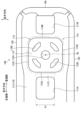
- the sealing member 300 is attached to the left side of the reinforcing frame 200, and is a member for sealing the material of the cushion member CU during manufacture of the armrest AR.
- the sealing member 300 is made of resin.
- the sealing member 300 includes a cylindrical portion 310, a first flat plate portion 320 extending in the longitudinal direction from the cylindrical portion 310, a second flat plate portion 330, and a rib 340. have.
- the first flat plate part 320 and the second flat plate part 330 are examples of flat plate parts.
- the cylindrical portion 310 is a portion that prevents the cushion member CU from entering the second shaft hole 214 during manufacture of the armrest AR.
- the cylindrical portion 310 has a base portion 311 , a bottom portion 312 provided on one end side of the base portion 311 , a flange portion 313 provided on the other end side of the base portion 311 , and a cap groove 314 .
- the base portion 311 has a cylindrical shape.
- the base portion 311 has an annular projection 311T that contacts the reinforcing frame 200.
- the protrusion 311T is located at the tip of one end of the base portion 311.
- the protrusion 311T has a tapered shape toward the tip that contacts the reinforcing frame 200.
- the protrusion 311T has flexibility.
- the protrusion 311T is in contact with a second portion 212B of the second convex portion 212, which is a slope formed on the reinforcing frame 200.
- the contact portion CP1 between the protrusion 311T and the reinforcing frame 200 surrounds the four second shaft holes 214.
- the bottom portion 312 is a wall formed at one end of the base portion 311.
- a third bolt hole 312A and a third shaft hole 312B are formed in the bottom portion 312.
- the third bolt hole 312A is a hole into which the bolt 91 (see FIG. 2) is inserted.
- the third bolt hole 312A is formed in a circular shape centered on the rotation axis RL.
- the third shaft hole 312B is a hole into which the extending portion 21A of the shaft 20 (see FIG. 2) engages, and a plurality of third shaft holes 312B, specifically four, are formed corresponding to the plurality of extending portions 21A of the shaft 20. has been done.
- the four third shaft holes 312B are each formed into a substantially trapezoidal shape when viewed from the direction of the rotation axis, and extend around the second bolt hole 213 on the circumference of a circle centered on the rotation axis RL. are placed side by side.
- the flange portion 313 has a donut shape and extends outward from the other end of the base portion 311 away from the rotation axis direction RL.
- the surface of the other end of the flange portion 313 in the rotational axis direction is inclined so as to approach the seat frame SF as it goes outward.
- the cap groove 314 is a groove into which the cap 50 (see FIG. 2) fits.
- the cap 50 serves as a lid for the cylindrical portion 310 and is a member that prevents the bolt 90 from being exposed.
- the first flat plate portion 320 contacts the reinforcing frame 200 and overlaps the first stopper portion 260 when viewed along the rotation axis direction.
- the first stopper portion 260 has the first recess 261 on the surface facing the first flat plate portion 320 .
- the first flat plate portion 320 is a portion that suppresses leakage of the material of the cushion member CU from the first stopper hole 262 during manufacture of the armrest AR.
- the first flat plate portion 320 extends from the cylindrical portion 310 toward the distal end side in the longitudinal direction. Note that, in the longitudinal direction, the reinforcing frame 200 extends to a position farther from the rotation axis RL than the first flat plate portion 320.
- the first flat plate portion 320 has a bottom portion 321 extending in the transverse direction, a first side portion 322 extending to the left from one end of the bottom portion 321, and a second side portion 323 extending to the left from the other end of the bottom portion 321.
- the bottom portion 321 contacts the reinforcing frame 200 and covers the first stopper hole 262.
- the contact portion CP1 between the protrusion 311T of the cylindrical portion 310 and the reinforcing frame 200 is farther from the seat frame SF than the contact portion CP2 between the first flat plate portion 320 and the reinforcing frame 200.
- the bottom portion 321 has a stepped portion 321D on the left side surface such that the distal end side in the longitudinal direction approaches the seat frame SF.
- the first side portion 322 includes a first extending portion 322E and a first claw portion 322T as an example of a claw portion.
- the first extending portion 322E is a wall that projects from the right end of the first side portion 322 to one side in the lateral direction and then extends to the left.
- the first claw portion 322T protrudes from the tip of the first extension portion 322E toward one side in the lateral direction.
- the first claw portion 322T is movable in the lateral direction by elastically deforming the first extending portion 322E in the lateral direction.
- the first claw portion 322T overlaps with the first stopper hole 262 in the longitudinal direction. Furthermore, when the sealing member 300 is attached to the reinforcing frame 200, the first extension portion 322E is elastically deformed, so the first claw portion 322T moves to the other side in the lateral direction. , and enters the right side of the second connecting portion C2. When the sealing member 300 is attached to the reinforcing frame 200, the first claw portion 322T is engaged with the second connecting portion C2. This prevents the sealing member 300 from easily coming off from the reinforcing frame 200.
- the second side portion 323 includes a second extending portion 323E and a second claw portion 323T as an example of a claw portion.
- the second extending portion 323E is a wall that projects from the right end of the second side portion 323 to the other side in the lateral direction and then extends to the left.
- the second claw portion 323T protrudes from the tip of the second extension portion 323E toward one side in the lateral direction.
- the second claw portion 323T is movable in the lateral direction by elastically deforming the second extending portion 323E in the lateral direction.
- the position of the second claw portion 323T in the longitudinal direction overlaps with the second stopper hole 272. Furthermore, when the sealing member 300 is attached to the reinforcing frame 200, the second extending portion 323E is elastically deformed, so the second claw portion 323T moves to the other side in the lateral direction. , and enters the right side of the first connecting portion C1. When the sealing member 300 is attached to the reinforcing frame 200, the second claw portion 323T is engaged with the first connecting portion C1. This prevents the sealing member 300 from easily coming off from the reinforcing frame 200.
- the second flat plate portion 330 contacts the reinforcing frame 200 and overlaps the second stopper portion 270 when viewed along the rotation axis direction.
- the second stopper portion 270 has the second recess 271 on the surface facing the second flat plate portion 330.
- the first flat plate portion 320 is a portion that suppresses the material of the cushion member CU from leaking from the second stopper hole 272 during manufacture of the armrest AR.
- the second flat plate portion 330 extends from the cylindrical portion 310 toward the base end side in the longitudinal direction. Note that, in the longitudinal direction, the reinforcing frame 200 extends to a position farther from the rotation axis RL than the first flat plate portion 320.
- the second flat plate portion 330 includes a bottom portion 331, a first side portion 332 extending to the left from one end of the bottom portion 331 in the lateral direction, and a second side portion 333 extending to the left from the other end of the bottom portion 331 in the lateral direction. has.
- the bottom portion 331 contacts the reinforcing frame 200 and covers the second stopper hole 272.
- the contact portion CP1 between the projection 311T of the cylindrical portion 310 and the reinforcing frame 200 is farther from the seat frame SF than the contact portion CP3 between the second flat plate portion 330 and the reinforcing frame 200.
- the bottom portion 331 has a convex portion 331T that fits into the second recess 271 of the second stopper portion 270.
- the protrusion amount D1 of the convex portion 331T is larger than the plate thickness D2 of the reinforcing frame 200.
- the bottom portion 331 has a stepped portion 331D on the left side surface such that the distal end side in the longitudinal direction approaches the seat frame SF.
- the rib 340 connects the cylindrical portion 310 and the first flat plate portion 320.
- the rib 340 overlaps the first claw part 322T and the second claw part 323T in the longitudinal direction.
- the rib 340 extends so as to straddle the stepped portion 321D.
- the skin member 40 is placed over the armrest RF.
- the skin member 40 has a first skin hole 41, a second skin hole 42, a third skin hole 43, a fourth skin hole 44, and a filling hole 45.
- the first skin hole 41 exposes the flange portion 313 of the cylindrical portion 310 of the sealing member 300.
- the edge of the first skin hole 41 has a smaller diameter than the outer periphery of the flange portion 313 and is in contact with the inner surface of the flange portion 313 (see also FIG. 9(b)).
- the second skin hole 42 exposes the first stopper portion 260 and the first hole 111A.
- the third skin hole 43 is a hole that exposes the second wall portion 112.
- the third skin hole 43 exposes the first bolt hole 112A and the first shaft hole 112B (see also FIG. 9(b)).
- the fourth skin hole 44 exposes the second stopper portion 270 and the second hole 111B.
- the filling hole 45 is a hole for filling the inside of the skin member 40 with the material of the cushion member CU. Note that the position of the filling hole 45 can be arbitrarily determined.
- the skin member 40 When the skin member 40 is placed over the armrest RF, the skin member 40 covers the armrest frame RF with the first shaft hole 112B and the second shaft hole 214, which are through holes, exposed.
- the armrest frame RF covered with the skin member 40 is placed in molds M1 and M2. Then, when the molds M1 and M2 are clamped, the sealing member 300 is pressed against the reinforcing frame 200. Then, as shown in FIG. 13(b), the protrusion 311T of the sealing member 300 that was in the state of FIG. The second portion 212B is deformed along the slope of the second portion 212B formed in the portion 212. In this way, as the protrusion 311T deforms along the slope as the mold is clamped, the formation of a gap between the reinforcing frame 200 and the sealing member 300 is suppressed, and the gap between the reinforcing frame 200 and the sealing member 300 is reduced. Improves sealing performance.
- the inside of the armrest frame RF is filled with the cushion member CU using the nozzle N. After inserting the nozzle N into the filling hole 45 of the skin member 40, when the material of the cushion member CU is filled, the cushion member CU is filled inside the armrest frame RF, as shown in FIGS. 8 and 9(b). .
- the edge of the first hole 41 of the skin member 40 is pressed from inside by the internal pressure of the material of the cushion member CU while in contact with the inner surface of the flange portion 313. Therefore, when filling with the material of the cushion member CU, no gap is created between the edge of the first hole 41 and the flange portion 313. As a result, the material of the cushion member CU hardly leaks from the first hole 41.
- the second skin hole 42, the third skin hole 43, and the fourth skin hole 44 are sandwiched between the main frame 100 and the mold M2. Therefore, when filling the material of the cushion member CU, no gap is created. As a result, the material of the cushion member CU hardly leaks from the second skin hole 42, the third skin hole 43, and the fourth skin hole 44.
- the cylindrical portion 310 prevents the material of the cushion member CU from entering from the outside to the inside of the cylindrical portion 310.
- the sealing performance between the reinforcing frame 200 and the sealing member 300 is improved by deforming the protrusion 311T of the cylindrical portion 310 along the slope of the second portion 212B. It does not enter inside the cylindrical portion 310. Therefore, when filling the material of the cushion member CU, the material of the cushion member CU does not easily leak from the first bolt hole 112A and the first shaft hole 112B due to the cylindrical portion 310 of the sealing member 300.
- the first flat plate portion 320 prevents the material of the cushion member CU from entering the first hole 111A. This makes it difficult for the material of the cushion member CU to leak from the first stopper hole 262.
- the second flat plate portion 330 prevents the material of the cushion member CU from entering the second hole 111B. This makes it difficult for the material of the cushion member CU to leak from the second stopper hole 272.
- the material of the cushion member CU is sealed by the sealing member 300 into the through holes (first bolt hole 112A, first shaft hole 112B, first hole 111A, second hole 111B, first It is possible to suppress leakage from the stopper hole 262 and the second stopper hole 272). As a result, the step of removing the protruding cushion member CU is not necessary.
- the reinforcing frame 200 had the first stopper part 260 and the second stopper part 270, but the present invention is not limited to this.
- the reinforcing frame may be configured to have only the first stopper part without the second stopper part.
- the reinforcing frame may be configured without the first stopper section and the second stopper section.
- the main frame may include a stopper portion that restricts the rotation range of the armrest.
- the armrest frame RF is configured to include the main frame 100 and the reinforcing frame 200, but the present invention is not limited to this.
- the frame of the armrest may be configured without a reinforcing frame.
- the frame of the armrest may be composed of three or more frames including the main frame.
- an armrest is exemplified as an example of a seat component that is rotatably attached to the seat frame around a rotational axis extending in the rotational axis direction, but the armrest is not limited to the armrest, and includes a headrest, a footrest, It may also be applied to other parts such as retractable tables.
- the armrest AR disposed on the left side of the seat back S1 is illustrated as an example of the armrest, but the armrest is not limited to this. That is, the armrest may be placed on the right side of the seat back.
- the armrest which is an example of the seat component according to the invention, is provided on the vehicle seat S mounted in the automobile, but the present invention is not limited thereto.
- the seat component may be provided in a vehicle seat mounted on a vehicle other than an automobile, specifically, a railway vehicle, a ship, an aircraft, or the like. Further, the seat component may be provided in a seat used at home or at a facility other than a vehicle seat.
Landscapes
- Engineering & Computer Science (AREA)
- Mechanical Engineering (AREA)
- Aviation & Aerospace Engineering (AREA)
- Transportation (AREA)
- Manufacturing & Machinery (AREA)
- Seats For Vehicles (AREA)
Abstract
シート部材の製造時に、クッション部材が貫通孔から漏れることを抑制する。アームレスト(AR)は、シートフレームに対して回動軸線方向に延びる回動軸線RL回りに回動可能に取り付けられ、フレーム(メインフレーム(100)および補強フレーム(200))と、表皮部材(40)と、封止部材(300)と、クッション部材(CU)とを備える。フレームは、回動軸線の周りに貫通孔(第1シャフト孔(112B)および第2シャフト孔(214))を有する。表皮部材(40)は、貫通孔を露出させた状態でフレームを覆う。封止部材(300)は、フレームに取り付けられる。クッション部材(CU)は、フレーム、封止部材(300)および表皮部材(40)の間の空間に充填されている。封止部材(300)は、フレームと接触する環状の突起(311T)を有する。突起(311T)とフレームの接触部分(CP1)は、貫通孔を囲んでいる。
Description
本発明は、シートフレームに対して回動可能に取り付けられるシート部品に関する。
従来、シートフレームに対して回動可能に取り付けられるシート部品としてのアームレストが知られている(特許文献1)。この技術では、アームレストは、フレームに表皮部材が被せられ、表皮部材の内部にクッション部材が充填されている。
ところで、シート部材の製造時において、フレームと表皮部材の間の空間にクッション部材を充填する工程がある。この工程では、クッション部材がフレームの貫通孔から漏れることがある。仮に、クッション部材がフレームの貫通口から漏れた場合には、はみ出たクッション材を取り除く工程が必要となるという問題点があった。
そこで、本発明は、シート部材の製造時において、クッション部材がフレームの貫通孔から漏れることを抑制することを目的とする。
前記した目的を達成するためのシート部品は、シートフレームに対して回動軸線方向に延びる回動軸線回りに回動可能に取り付けられ、フレームと、表皮部材と、封止部材と、クッション部材と、を備える。
フレームは、シート部品の骨格を構成する。フレームは、回動軸線の周りに貫通孔を有する。表皮部材は、貫通孔を露出させた状態でフレームを覆う。封止部材は、フレームに取り付けられる。クッション部材は、フレーム、封止部材および表皮部材の間の空間に充填されている。
封止部材は、フレームと接触する環状の突起を有する。
突起とフレームの接触部分は、貫通孔を囲んでいる。
フレームは、シート部品の骨格を構成する。フレームは、回動軸線の周りに貫通孔を有する。表皮部材は、貫通孔を露出させた状態でフレームを覆う。封止部材は、フレームに取り付けられる。クッション部材は、フレーム、封止部材および表皮部材の間の空間に充填されている。
封止部材は、フレームと接触する環状の突起を有する。
突起とフレームの接触部分は、貫通孔を囲んでいる。
このような構成によれば、シート部材の製造時において、封止部材によって、クッション部材がシート部材の貫通孔から漏れることを抑制できる。このため、貫通孔からはみ出たクッション部材を取り除く工程を削減できる。
前記したシート部品において、封止部材の突起は、フレームに接する先端に行くにつれて細い先細り形状を有する構成としてもよい。
これによれば、突起がフレームと接触する場合に変形するため、フレームと封止部材のシール性が向上する。
前記したシート部品において、封止部材の突起は可撓性を有する構成としてもよい。
これによれば、突起がフレームと接触する場合に変形するため、フレームと封止部材のシール性が向上する。
前記したシート部品において、フレームは封止部材の貫通孔を囲むように配置された、回動軸線に直交する面に対して傾いた斜面を有し、封止部材の突起は、斜面に接触している構成としてもよい。
前記したシート部品において、封止部材は円筒部と円筒部からフレームの長手方向に延びる平板部と、を有しており、平板部はフレームに接触し、突起とフレームとの接触部分は、平板部とフレームとの接触部分よりもシートフレームから離れている構成としてもよい。
前記したシート部品において、フレームは、シートフレームに向けて突出し、シート部品が回動する範囲を規制するストッパと、ストッパに形成されたストッパ孔と、をさらに有し、平板部は、回動軸線方向に沿って見てストッパと重なり、ストッパ孔間からクッション部材の材料が漏れるのを抑制する構成としてもよい。
これによれば、封止部材の平板部がストッパと重なることで、ストッパ孔からクッション部材の材料が漏れるのを抑制することができる。
前記したシート部品において、フレームは、メインフレームと、補強フレームとを有してなり、メインフレームはストッパ挿通孔を有し、補強フレームは、ストッパおよびストッパ孔を有し、ストッパは、ストッパ挿通孔に入り込み、ストッパ挿通孔からシートフレームに向けて突出している構成としてもよい。
これによれば、ストッパは、ストッパ挿通孔からシートフレームに向けて突出していることで、シート部品が回動する範囲を規制することができる。
前記したシート部品において、ストッパは、平板部に対向する面に凹部を有し、平板部は、凹部に入り込む凸部を有する構成としてもよい。
これによれば、ストッパの凹部に平面部の凸部が入り込むことで、平面部がストッパに対して位置決めされる。
前記したシート部品において、補強フレームは金属板からなり、凸部の突出量は、補強フレームの板厚よりも大きい構成としてもよい。
前記したシート部品において、封止部材は、平板部から延出する爪部であってフレームと係合する爪部を有し、爪部は、長手方向における位置が、ストッパ孔と重なる構成としてもよい。
次に、発明の一実施形態について、適宜図面を参照しながら詳細に説明する。なお、本明細書において、前後、左右、上下は、アームレストARを備えるシートに座った者から見た、前後、左右、上下を基準とする。
図1に示すように、シートは、自動車に搭載される車両用シートSとして構成されており、シートバックS1と、シートクッションS2と、ヘッドレストHRと、シート部品の一例としてのアームレストARとを備えている。
車両用シートSには、シートバックS1およびシートクッションS2の骨格を構成するシートフレームSFが内蔵されている。シートバックS1およびシートクッションS2は、シートフレームSFに、ウレタンフォームなどのクッション材からなるパッドと、皮革や布地などからなる表皮材を被せることで構成されている。シートフレームSFは、シートバックS1の左右のフレームを構成するサイドフレームS11と、左のサイドフレームS11に固定されたブラケット10とを有している。
アームレストARは、シートバックS1の左側に配置され、シートフレームSFに対して回動可能に取り付けられている。詳しくは、アームレストARは、長手方向の一端部がシャフト20(図2参照)に固定され、シャフト20がブラケット10に回動可能に支持されることで、シートフレームSFに対して回動可能に取り付けられている。
アームレストARは、先端が前を向く実線で示した引出状態と、先端が上を向く仮想線(二点鎖線)で示した収納状態との間で回動可能である。なお、アームレストARは、例えば、ワンウェイクラッチによって、引出状態から収納状態へ向けての所定の角度範囲では、上方向への回動のみが許容され、下方向への回動が規制されるように設けられていてもよい。
図1、図2に示すように、アームレストARは、フレームの一例としてのアームレストフレームRFと、表皮部材40と、クッション部材CU(図8参照)と、封止部材300とを備える。
表皮部材40は、皮革や布地などからなり、アームレストフレームRFを覆う部材である。クッション部材CUは、発泡ポリウレタンなどの発泡樹脂であり、アームレストフレームRF、封止部材300および表皮部材40の間の空間に充填されている(図8参照)。
図2に示すように、アームレストフレームRFは、メインフレーム100と、補強フレーム200と、スペーサ600と、を有している。メインフレーム100は、アームレストARの骨格を構成する長尺のフレームであり、金属板を板金加工することにより形成されている。
ここで、本実施形態においては、メインフレーム100を基準として、右側が「シートフレーム側」に相当し、左側が「シートフレーム側とは反対側」に相当する。また、以下では、アームレストARの長手方向における、メインフレーム100や補強フレーム200の端のうち、アームレストARの回動軸線RLに近い方の端を基端といい、回動軸線RLから遠い方の端を先端というものとする。また、基端側の端部を基端部といい、先端側の端部を先端部ということがある。
また、以下の説明では、アームレストAR(メインフレーム100)の長手方向を単に「長手方向」ということがある。また、回動軸線RLが延びる方向と平行な方向である、アームレストARの回動軸線方向を単に「回動軸線方向」ということがある。本実施形態において、回動軸線方向は、左右方向に相当する。さらに、回動軸線方向および長手方向に直交する方向を「短手方向」という。
図3、図4に示すように、メインフレーム100は、長尺のメインベース壁110と、第1メイン側壁120と、第2メイン側壁130と、第3メイン側壁140と、第4メイン側壁150とを有している。
メインベース壁110は、シートフレームSFに対して回動可能に取り付けられる壁である。また、第1メイン側壁120は、メインベース壁110の縁部のうち、短手方向一方側の縁部から左側に延びる壁であり、第2メイン側壁130は、メインベース壁110の縁部のうち、短手方向他方側の縁部から左側に延びる壁である。また、第3メイン側壁140は、メインベース壁110の縁部のうち、基端側の縁部から左側に延びる壁であり、第4メイン側壁150は、メインベース壁110の縁部のうち、先端側の縁部から左側に延びる壁である。
図5に示すように、メインベース壁110は、第1壁部111と、第2壁部112と、接続壁部113とを有している。第2壁部112および接続壁部113は、メインベース壁110の基端部に位置している。
第1壁部111は、第1孔111Aと、第2孔111Bとを有している。また、第1壁部111は、脆弱部111Cを有している。
第1壁部111は、第1孔111Aと、第2孔111Bとを有している。また、第1壁部111は、脆弱部111Cを有している。
第1孔111Aは、補強フレーム200の後述する第1ストッパ部260(図3(b)参照)を通過させるための略矩形状の孔であり、脆弱部111Cよりも、長手方向におけるアームレストARの先端側に配置されている。また、第2孔111Bは、補強フレーム200の後述する第2ストッパ部270(図3(b)参照)を通過させるための略矩形状の孔であり、長手方向において回動軸線RLに対して第1孔111Aとは反対側に位置している。第1孔111Aおよび第2孔111Bは、ストッパ挿通孔の一例である。第2壁部112および接続壁部113(後述する凸部114)は、長手方向における第1孔111Aと第2孔111Bとの間に設けられている。
脆弱部111Cは、第1孔111Aと、第2壁部112に設けられた複数の孔112A,112Bとの間に位置していることで、脆弱部111C自身の短手方向両側に位置する部分や、第2壁部112の短手方向両側に位置する部分などと比較して、応力がかかりやすい部分である。
第2壁部112は、シートフレームSFに対して回動可能に取り付けられる部分であり、第1壁部111に対して回動軸線方向のシートフレームSF側、すなわち、右側にずれて配置されている。
第2壁部112は、第1ボルト孔112Aと、第1シャフト孔112Bとを有している。第1ボルト孔112Aは、シャフト20をアームレストフレームRFに固定するためのボルト91(図2参照)が挿通される孔であり、第2壁部112の略中央に1つ形成されている。第1ボルト孔112Aは、回動軸線RLを中心とする円形状に形成されている。
第1シャフト孔112Bは、シャフト20の後述する延出部21A(図2参照)が通る孔であり、シャフト20の複数の延出部21Aに対応して複数、具体的には、4つ形成されている。4つの第1シャフト孔112Bは、回動軸線方向から見て、それぞれ略円弧状に形成されており、第1ボルト孔112Aの周囲で、回動軸線RLを中心とする円の円周上に並んで配置されている。第1シャフト孔112Bは、回動軸線の周りの貫通孔の一例である。
接続壁部113は、第1壁部111と第2壁部112を接続する部分である。接続壁部113は、四角形状の第2壁部112に対応して4つの部分を有している。詳しくは、接続壁部113は、第1接続壁部113Aと、第2接続壁部113Bと、第3接続壁部113Cと、第4接続壁部113Dとを含み、第2壁部112を取り囲むような四角い枠状に形成されている。各接続壁部113A~113Dは、それぞれ、第2壁部112に近づくにつれて右側に位置するように、回動軸線方向に対して傾斜している。
第2壁部112および接続壁部113は、第1壁部111に対して右側(図5の紙面奥側)に突出する凸部114を形成している。凸部114は、回動軸線方向から見て、四角形状である。
図4に戻り、メインベース壁110は、複数の貫通孔115A~115Eと、中央凸部116とをさらに有している。
貫通孔115A~115Eは、メインフレーム100を軽量化するために形成された孔である。貫通孔115A~115Eは、先端側から基端側に向けて長手方向にこの順に並んで形成されている。4つの貫通孔115A,115C~115Eは、長手方向に長い略長円形状であり、貫通孔115Bは、略円形状である。貫通孔115A~115Cは、中央凸部116よりも先端側のメインベース壁110の先端部に形成されており、貫通孔115D,115Eは、中央凸部116に形成されている。
中央凸部116は、第1壁部111に対して左側に突出する凸部である。中央凸部116は、メインベース壁110の長手方向における中央部付近において、長手方向に長い略長円形状に形成されている。
図6(a),(b)に示すように、補強フレーム200は、メインフレーム100を補強するためのフレームであり、メインフレーム100と同様に、金属板を板金加工することにより形成されている。補強フレーム200は、メインフレーム100を構成する板状部材よりも厚い板厚の板状部材から形成されている。一例として、補強フレーム200の板厚は、メインフレーム100の板厚のおよそ1.5倍である。
補強フレーム200は、補強ベース壁210と、第1補強側壁220と、第2補強側壁230と、第3補強側壁240と、第4補強側壁250と、第1ストッパ部260と、第2ストッパ部270とを有している。第1ストッパ部260および第2ストッパ部270は、ストッパの一例である。
補強ベース壁210は、メインフレーム100のメインベース壁110に重なるように配置される壁である。また、第1補強側壁220は、補強ベース壁210の縁部のうち、短手方向一方側の縁部から左側に延びる壁であり、第2補強側壁230は、補強ベース壁210の縁部のうち、短手方向他方側の縁部から左側に延びる壁である。また、第3補強側壁240は、補強ベース壁210の縁部のうち、長手方向におけるアームレストARの基端側に位置する縁部から左側に延びる壁である。
補強ベース壁210は、基部211と、第2凸部212と、第2ボルト孔213と、第2シャフト孔214とを有している。
第2凸部212は、基部211に対して回動軸線方向、具体的には、左側に突出する凸部である。第2凸部212は、回動軸線方向から見てメインフレーム100の凸部114と重なる位置で略円形状に形成されている。第2凸部212は、基部211に対して左側にずれて配置された第1部位212Aと、基部211と略円形状の第1部位212Aの周縁部を接続する第2部位212Bと、突起部212Cとを有している。第2部位212Bは、4つの第2シャフト孔214を囲むように配置されている。第2部位212Bは、回動軸線に直交する面に対して傾いた斜面であり、後述する封止部材300の突起311Tが接触する部位である。
突起部212Cは、回動軸線方向から見て、第2凸部212から、回動軸線RLを中心とする円の径方向に突出するように設けられている。突起部212Cは、複数、具体的には、4つ設けられている。
第2ボルト孔213および第2シャフト孔214は、第2凸部212の第1部位212Aに形成されている。
第2ボルト孔213は、ボルト91(図2参照)が挿通される孔であり、第1部位212Aの略中央に1つ形成されている。第1ボルト孔112Aは、回動軸線RLを中心とする円形状に形成されている。第2ボルト孔213の周縁部には、バーリング加工などにより右側に突出するフランジ部213Aが形成されている。
第2ボルト孔213は、ボルト91(図2参照)が挿通される孔であり、第1部位212Aの略中央に1つ形成されている。第1ボルト孔112Aは、回動軸線RLを中心とする円形状に形成されている。第2ボルト孔213の周縁部には、バーリング加工などにより右側に突出するフランジ部213Aが形成されている。
第2シャフト孔214は、シャフト20の延出部21A(図2参照)が係合する孔であり、シャフト20の複数の延出部21Aに対応して複数、具体的には、4つ形成されている。4つの第2シャフト孔214は、回動軸線方向から見て、それぞれ略台形状に形成されており、第2ボルト孔213の周囲で、回動軸線RLを中心とする円の円周上に並んで配置されている。
第4補強側壁250は、補強ベース壁210の縁部のうち、長手方向におけるアームレストARの先端側に位置する縁部から左側に立ち上がる壁である。第4補強側壁250は、回動軸線方向から見て、短手方向の中央部251が、短手方向の両端部252,253に対し、長手方向にずれた位置に位置する形状である。詳しくは、第4補強側壁250は、回動軸線方向から見て、中央部251が両端部252,253に対して長手方向における基端側にずれた位置に位置するように略V字形状に屈曲して形成されている。
図7に示すように、補強フレーム200は、メインフレーム100を挟んでブラケット10(シートフレームSF)とは反対側の左側に配置され、メインフレーム100の基端部に重なって設けられている(図2も参照)。詳しくは、補強フレーム200は、補強ベース壁210がメインベース壁110を挟んでブラケット10とは反対側でメインベース壁110の基端部に接触して重なって設けられている。また、補強フレーム200は、第1補強側壁220が第1メイン側壁120の短手方向の内側で第1メイン側壁120に重なって設けられ、第2補強側壁230が第2メイン側壁130の短手方向の内側で第2メイン側壁130に重なって設けられている。さらに、補強フレーム200は、第3補強側壁240が第3メイン側壁140の長手方向の内側で第3メイン側壁140に重なって設けられている。
メインフレーム100と補強フレーム200は、第1連結部C1、第2連結部C2および第3連結部C3で互いに連結されている。具体的には、補強フレーム200とメインフレーム100は、基端部において、回動軸線RLよりも先端側の部分が第1連結部C1と第2連結部C2で互いに連結されており、かつ、回動軸線RLよりも基端側の部分が第3連結部C3で互いに連結されている。
図9(a)に示すように、第1連結部C1は、第1メイン側壁120に形成される折り返し部121と、第1補強側壁220に形成される折り返し部221とが重なった部分である。折り返し部121は、第1メイン側壁120の端部の一部をメインベース壁110側に折り返した部分であり、折り返し部221は、第1補強側壁220の端部の一部を補強ベース壁210側に折り返した部分である。
また、第2連結部C2は、第2メイン側壁130に形成される折り返し部131と、第2補強側壁230に形成される折り返し部231とが重なった部分である。折り返し部131は、第2メイン側壁130の端部の一部をメインベース壁110側に折り返した部分であり、折り返し部231は、第2補強側壁230の端部の一部を補強ベース壁210側に折り返した部分である。第1連結部C1と第2連結部C2は、短手方向に略対称に設けられている。
図8に示すように、第3連結部C3は、第3メイン側壁140に形成される折り返し部141と、第3補強側壁240に形成される折り返し部241とが重なった部分である。折り返し部141は、第3メイン側壁140の端部の一部をメインベース壁110側に折り返した部分であり、折り返し部241は、第3補強側壁240の端部を補強ベース壁210側に折り返した部分である。
図7に示すように、補強フレーム200に設けられた第1ストッパ部260および第2ストッパ部270は、シートフレームSFの一部に当接してアームレストARの回動範囲を規制する部分である。詳しくは、第1ストッパ部260および第2ストッパ部270は、サイドフレームS11に固定されたブラケット10に当接してアームレストARの回動する範囲を規制する。
図6(a)に示すように、第1ストッパ部260は、第1凹部261と、第1ストッパ孔262とを有している。第1凹部261は、第1ストッパ部260に形成された凹みである。第1ストッパ孔262は、第1ストッパ部260に形成された孔である。
具体的には、第1ストッパ部260は、金属板に2本の平行線の切り込みを入れた後、2本の平行線の間を押し出すことにより作られる。第1凹部262は、2本の平行線の間を押し出されたときに生じた凹みである。第1ストッパ孔262は、2本の平行線の間を押し出されたときに生じた孔である。
具体的には、第1ストッパ部260は、金属板に2本の平行線の切り込みを入れた後、2本の平行線の間を押し出すことにより作られる。第1凹部262は、2本の平行線の間を押し出されたときに生じた凹みである。第1ストッパ孔262は、2本の平行線の間を押し出されたときに生じた孔である。
また、第2ストッパ部270は、第2凹部271と、第2ストッパ孔272とを有している。第2凹部271は、第2ストッパ部270に形成された凹みである。第2ストッパ孔272は、第2ストッパ部270に形成された孔である。
具体的には、第2ストッパ部270は、金属板に2本の平行線の切り込みを入れた後、2本の平行線の間を押し出すことにより作られる。第2凹部272は、2本の平行線の間を押し出されたときに生じた凹みである。第2ストッパ孔272は、2本の平行線の間を押し出されたときに生じた孔である。
なお、第1ストッパ孔262および第2ストッパ孔272は、ストッパ孔の一例である。
具体的には、第2ストッパ部270は、金属板に2本の平行線の切り込みを入れた後、2本の平行線の間を押し出すことにより作られる。第2凹部272は、2本の平行線の間を押し出されたときに生じた凹みである。第2ストッパ孔272は、2本の平行線の間を押し出されたときに生じた孔である。
なお、第1ストッパ孔262および第2ストッパ孔272は、ストッパ孔の一例である。
第1ストッパ部260は、メインフレーム100の第1孔111Aに入り込み、第1孔111AからシートフレームSFに向けて、回動軸線方向に突出している。言い換えると、第1ストッパ部260は、メインフレーム100の第1孔111Aを通るように、基部211に対して右側に突出している。第1ストッパ部260は、回転軸線方向において、メインフレーム100のメインベース壁110、詳しくは、第2壁部112よりも右側に突出している。第1ストッパ部260は、長手方向において第4補強側壁250と回動軸線RLとの間に配置されている。詳しくは、第1ストッパ部260は、長手方向において第4補強側壁250と第2凸部212との間に配置されている。また、第1ストッパ部260は、短手方向において第1連結部C1と第2連結部C2との間に配置されている。
第2ストッパ部270は、メインフレーム100の第2孔111Bに入り込み、第2孔111BからシートフレームSFに向けて、回動軸線方向に突出している。言い換えると、第2ストッパ部270は、メインフレーム100の第2孔111Bを通るように、基部211に対して右側に突出している。第2ストッパ部270は、第1ストッパ部260と同様に、回転軸線方向において、第2壁部112よりも右側に突出している。第2ストッパ部270は、長手方向において回動軸線RLに対して第1ストッパ部260とは反対側に配置されている。言い換えると、第2ストッパ部270は、長手方向において第3補強側壁240と回動軸線RLとの間に配置されている。詳しくは、第2ストッパ部270は、長手方向において第3補強側壁240と第2凸部212との間に配置されている。
図2に示すように、スペーサ600は、メインフレーム100と補強フレーム200との間に設けられている。スペーサ600は、リング部610と、延出部620とを有する。リング部610は、ボルト90が通る貫通孔を有する。延出部620は、リング部610の外周から、シャフト20の4つ凸部21Aの間に向けて延出している。スペーサ600が設けられることで、回転トルクが掛かるシャフト20の凸部21Aの付近におけるメインフレーム100と補強フレーム200の間隔が確保され、アームレストRの剛性を高くすることができる。
ブラケット10は、アームレストフレームRF(アームレストAR)を回動可能に支持する部材であり、金属板を板金加工することにより形成されている。ブラケット10は、サイドフレームS11とアームレストフレームRFとの間に配置されている。ブラケット10は、ブラケットベース壁11と、ブラケット側壁12とを有している。ブラケット側壁12は、ブラケットベース壁11の縁部から右側に延びる壁である。ブラケット10は、ブラケット側壁12の端部がサイドフレームS11に溶接などにより固定されることで、サイドフレームS11に固定されている。
ブラケットベース壁11は、シャフト20を回動可能に支持する軸支孔11Aを有している。軸支孔11Aの周縁部には、バーリング加工などにより回動軸線RLに沿って延びるフランジ部11Bが形成されている。また、ブラケットベース壁11は、軸支孔11Aの前斜め下の位置で左側に突出するように設けられた第1規制部11Cと、軸支孔11Aの後ろ斜め上の位置で左側に突出するように設けられた第2規制部11Dとを有している。第1規制部11Cおよび第2規制部11Dは、回動軸線方向から見て、軸支孔11Aを挟むように配置され、回動軸線方向から見て、それぞれが略円弧状をなすように形成されている。
図7に示すように、アームレストARは、第1ストッパ部260が第1規制部11Cの上端に当接し、第2ストッパ部270が第2規制部11Dの下端に当接したときに引出状態よりも下方への回動が規制される。また、アームレストARは、第1ストッパ部260がブラケット10の第2規制部11Dの上端に当接し、第2ストッパ部270が第1規制部11Cの下端に当接したときに収納状態よりも後方への回動が規制される。
図2に戻り、シャフト20は、金属からなる筒状の部材であり、小径部21と、小径部21よりも若干大径に形成された大径部22とを有している。シャフト20は、小径部21がブラケット10の軸支孔11A(フランジ部11B)に回動可能に軸支され、大径部22がフランジ部11Bの右側の端部に当接可能となっていることで、アームレストフレームRFがブラケット10から左へ外れるのを抑制する。
小径部21は、左側の端部に、左側に向けて延びる複数、具体的には、4つの延出部21Aを有している。4つの延出部21Aは、回動軸線方向から見て、それぞれ略円弧状に形成されており、アームレストフレームRFのシャフト孔112B,214に対応して、回動軸線RLを中心とする円の円周上に並んで配置されている。また、小径部21は、左側の端部のうち、延出部21Aの間の部分に、シャフト20の径方向内側に向けて略90°に折り曲げて形成された複数の折曲部21Bを有している。シャフト20の内側には、ナット92が配置されており、ナット92は、複数の折曲部21Bに溶接などにより接合されている。
シャフト20は、4つの延出部21Aが、それぞれ、ワッシャ30のシャフト孔32およびメインフレーム100の第1シャフト孔112Bを通って、補強フレーム200の第2シャフト孔214に係合している。そして、ボルト91を、補強フレーム200の第2ボルト孔213、メインフレーム100の第1ボルト孔112Aおよびワッシャ30のボルト孔31を通して、シャフト20に固定されたナット92に締結することで、シャフト20がアームレストフレームRF(アームレストAR)に固定されている。これにより、アームレストフレームRFとシャフト20は、ブラケット10に対して一体で回動可能となっている。なお、ワッシャ30のシャフト孔32は、シャフト孔112B,214と同様に、4つがそれぞれ略円弧状に形成されており、回動軸線RLを中心とする円の円周上に並んで配置されている。
図2に示すように、封止部材300は、補強フレーム200の左側に取り付けられ、アームレストARの製造時にクッション部材CUの材料を封止するための部材である。封止部材300は、樹脂からなる。図10(a),(b)に示すように、封止部材300は、円筒部310と、円筒部310から長手方向に延びる第1平板部320と、第2平板部330と、リブ340とを有している。第1平板部320および第2平板部330は、平板部の一例である。
円筒部310は、アームレストARの製造時に、クッション部材CUが第2シャフト孔214に入り込むのを防ぐ部分である。円筒部310は、ベース部311と、ベース部311の一端側に設けられた底部312と、ベース部311の他端側に設けられたフランジ部313と、キャップ溝314と、を有する。
ベース部311は、円筒形状を有する。ベース部311は、補強フレーム200と接触する環状の突起311Tを有する。
図8に示すように、突起311Tは、ベース部311の一端側の先端に位置する。突起311Tは、補強フレーム200に接する先端に行くにつれて細い先細り形状を有する。突起311Tは可撓性を有する。突起311Tは、補強フレーム200に形成されている斜面である第2凸部212の第2部位212Bに接触している。図7に二点鎖線で示すように、突起311Tと補強フレーム200の接触部分CP1は、4つの第2シャフト孔214を囲んでいる。
図10(a),(b)に戻り、底部312は、ベース部311の一端に形成された壁である。底部312には、第3ボルト孔312Aと、第3シャフト孔312Bが形成されている。第3ボルト孔312Aは、ボルト91(図2参照)が挿通される孔である。第3ボルト孔312Aは、回動軸線RLを中心とする円形状に形成されている。第3シャフト孔312Bは、シャフト20の延出部21A(図2参照)が係合する孔であり、シャフト20の複数の延出部21Aに対応して複数、具体的には、4つ形成されている。4つの第3シャフト孔312Bは、回動軸線方向から見て、それぞれ略台形状に形成されており、第2ボルト孔213の周囲で、回動軸線RLを中心とする円の円周上に並んで配置されている。
フランジ部313は、ドーナツ形状を有し、ベース部311の他端から回動軸線方向RLから離れるように外側に延びている。フランジ部313の回動軸線方向における他端側の面は、外側にいくにつれてシートフレームSFに近づくように傾斜している。
キャップ溝314は、キャップ50(図2参照)が嵌る溝である。キャップ50は、円筒部310の蓋となり、ボルト90が露出しないようにする部材である。
第1平板部320は、補強フレーム200と接触し、回動軸線方向に沿って見て第1ストッパ部260と重なる。別の言い方をすると、第1ストッパ部260は、第1平板部320に対向する面に第1凹部261を有する。第1平板部320は、アームレストARの製造時に、第1ストッパ孔262からクッション部材CUの材料が漏れるのを抑制する部分である。
第1平板部320は、円筒部310から長手方向の先端側に延びている。なお、長手方向において、補強フレーム200は、第1平板部320よりも、回動軸線RLから遠い位置まで延びている。第1平板部320は、短手方向に延びる底部321と、底部321の一端から左に延びる第1側部322と、底部321の他端から左に延びる第2側部323と、を有する。
図8に示すように、底部321は、補強フレーム200と接触し、第1ストッパ孔262を覆う。円筒部310の突起311Tと補強フレーム200との接触部分CP1は、第1平板部320と補強フレーム200との接触部分CP2よりもシートフレームSFから離れている。底部321は、左側面に長手方向の先端側がシートフレームSFに近づくような段差部321Dを有している。
図10(a),(b)に示すように、第1側部322は、第1延出部322Eと、爪部の一例としての第1爪部322Tと、を有する。第1延出部322Eは、第1側部322の右端から短手方向の一方側に突出した後、左に延出する壁である。第1爪部322Tは、第1延出部322Eの先端部から短手方向の一方側に突出している。第1爪部322Tは、第1延出部322Eが短手方向に弾性変形することで、短手方向に移動可能である。
図9(a)に示すように、第1爪部322Tは、長手方向における位置が、第1ストッパ孔262と重なる。また、第1爪部322Tは、封止部材300が補強フレーム200に取り付けられる場合、第1延出部322Eが弾性変形するので、第1爪部322Tが短手方向の他方側に移動して、第2連結部C2の右側に入り込むようになっている。封止部材300が補強フレーム200に取り付けられた場合、第1爪部322Tは、第2連結部C2と係合している。これにより、封止部材300が補強フレーム200から簡単に抜けないようになっている。
図10(a),(b)に示すように、第2側部323は、第2延出部323Eと、爪部の一例としての第2爪部323Tと、を有する。第2延出部323Eは、第2側部323の右端から短手方向の他方側に突出した後、左に延出する壁である。第2爪部323Tは、第2延出部323Eの先端部から短手方向の一方側に突出している。第2爪部323Tは、第2延出部323Eが短手方向に弾性変形することで、短手方向に移動可能である。
図9(a)に示すように、第2爪部323Tは、長手方向における位置が、第2ストッパ孔272と重なる。また、第2爪部323Tは、封止部材300が補強フレーム200に取り付けられる場合、第2延出部323Eが弾性変形するので、第2爪部323Tが短手方向の他方側に移動して、第1連結部C1の右側に入り込むようになっている。封止部材300が補強フレーム200に取り付けられた場合、第2爪部323Tは、第1連結部C1と係合している。これにより、封止部材300が補強フレーム200から簡単に抜けないようになっている。
図8に示すように、第2平板部330は、補強フレーム200と接触し、回動軸線方向に沿って見て第2ストッパ部270と重なる。別の言い方をすると、第2ストッパ部270は、第2平板部330に対向する面に第2凹部271を有する。第1平板部320は、アームレストARの製造時に、第2ストッパ孔272からクッション部材CUの材料が漏れるのを抑制する部分である。
図10に示すように、第2平板部330は、円筒部310から長手方向の基端側に延びている。なお、長手方向において、補強フレーム200は、第1平板部320よりも、回動軸線RLから遠い位置まで延びている。第2平板部330は、底部331と、底部331の短手方向の一端から左に延びる第1側部332と、底部331の短手方向の他端から左に延びる第2側部333と、を有する。
図8に示すように、底部331は、補強フレーム200と接触し、第2ストッパ孔272を覆う。円筒部310の突起311Tと補強フレーム200との接触部分CP1は、第2平板部330と補強フレーム200との接触部分CP3よりもシートフレームSFから離れている。
底部331は、第2ストッパ部270の第2凹部271に入り込む凸部331Tを有する。凸部331Tの突出量D1は、補強フレーム200の板厚D2よりも大きい。底部331は、左側の面に長手方向の先端側がシートフレームSFに近づくような段差部331Dを有している。
図10(a)に示すように、リブ340は、円筒部310と第1平板部320とをつないでいる。リブ340は、長手方向における位置が第1爪部322Tおよび第2爪部323Tと重なる。また、リブ340は、段差部321Dに跨るように延びている。
次に、本実施形態に係るアームレストARの製造方法および作用効果について説明する。
アームレストARを製造する場合には、まず、図11に示すように、アームレストフレームRFに封止部材300を取り付けた状態で、アームレストRFに表皮部材40を被せる。
ここで、表皮部材40は、第1表皮孔41と、第2表皮孔42と、第3表皮孔43と、第4表皮孔44と、充填孔45と、を有する。第1表皮孔41は、封止部材300の円筒部310のフランジ部313を露出させる。第1表皮孔41の縁は、フランジ部313の外周より直径が小さくフランジ部313の内側面に接触している(図9(b)も参照)。第2表皮孔42は、第1ストッパ部260と、第1孔111Aを露出させる。
第3表皮孔43は、第2壁部112を露出させる孔である。第3表皮孔43は、第1ボルト孔112Aと第1シャフト孔112Bとを露出させる(図9(b)も参照)。第4表皮孔44は、第2ストッパ部270と、第2孔111Bを露出させる。充填孔45は、表皮部材40の内部にクッション部材CUの材料を充填するための孔である。なお、充填孔45の位置は、任意に決定できる。
アームレストRFに表皮部材40を被せた状態において、表皮部材40は、貫通孔である第1シャフト孔112Bおよび第2シャフト孔214を露出させた状態でアームレストフレームRFを覆う。
次に、図12に示すように、表皮部材40を被せたアームレストフレームRFを成形型M1,M2に入れる。そして、成形型M1,M2を型締めすると、封止部材300が補強フレーム200に押し付けられる。すると、図13(a)の状態であった封止部材300の突起311Tは、図13(b)に示すように、可撓性を有し、先細り形状の先端が補強フレーム200の第2凸部212に形成されている第2部位212Bの斜面に沿って変形する。このように、型締めに伴って、突起311Tが斜面に沿って変形することにより、補強フレーム200と封止部材300の間に隙間が生じることが抑制され、補強フレーム200と封止部材300のシール性が向上する。
次に、図12に戻り、ノズルNを用いて、アームレストフレームRFの内部にクッション部材CUを充填させる。ノズルNを表皮部材40の充填孔45に差し込んだ後、クッション部材CUの材料を充填すると、図8および図9(b)に示すように、クッション部材CUがアームレストフレームRFの内部に充填される。
クッション部材CUの材料を充填するとき、表皮部材40の第1孔41の縁は、フランジ部313の内側面に接触した状態で、クッション部材CUの材料の内圧で内側から押される。このため、クッション部材CUの材料を充填するときに、第1孔41の縁とフランジ部313の間に隙間が生ずることがない。この結果、第1孔41からはクッション部材CUの材料が漏れにくい。
また、第2表皮孔42、第3表皮孔43および第4表皮孔44は、メインフレーム100と成形型M2に挟まれている。このため、クッション部材CUの材料を充填するときに、隙間が生ずることがない。この結果、第2表皮孔42、第3表皮孔43および第4表皮孔44からはクッション部材CUの材料が漏れにくい。
また、図8および図9(b)に示すように、クッション部材CUの材料を充填するときに、円筒部310は、クッション部材CUの材料が円筒部310の外側から内側に入り込むのを防ぐ。特に、円筒部310の突起311Tが第2部位212Bの斜面に沿って変形することにより、補強フレーム200と封止部材300のシール性が向上しているため、簡単にはクッション部材CUの材料が円筒部310の内側に入り込まない。このため、クッション部材CUの材料を充填するときに、封止部材300の円筒部310によって、第1ボルト孔112Aおよび第1シャフト孔112Bからは、クッション部材CUの材料が漏れにくい。
また、図8に示すように、クッション部材CUの材料を充填するときに、第1平板部320は、第1孔111Aにクッション部材CUの材料が入り込むのを防ぐ。これにより、第1ストッパ孔262からクッション部材CUの材料が漏れにくい。
また、クッション部材CUの材料を充填するときに、第2平板部330は、第2孔111Bにクッション部材CUの材料が入り込むのを防ぐ。これにより、第2ストッパ孔272からクッション部材CUの材料が漏れにくい。
このように、アームレストARの製造時において、封止部材300によって、クッション部材CUの材料が貫通口(第1ボルト孔112A、第1シャフト孔112B、第1孔111A、第2孔111B、第1ストッパ孔262および第2ストッパ孔272)から漏れることを抑制できる。この結果、はみ出たクッション部材CUを取り除く工程が必要なくなる。
以上に発明の一実施形態について説明したが、本発明は前記実施形態に限定されることなく、以下に例示するように適宜変形して実施することができる。
また、前記実施形態では、補強フレーム200が、第1ストッパ部260と、第2ストッパ部270とを有していたが、これに限定されない。例えば、補強フレームは、第2ストッパ部を備えず、第1ストッパ部のみを有する構成であってもよい。また、補強フレームは、第1ストッパ部および第2ストッパ部を備えない構成であってもよい。また、メインフレームがアームレストの回動範囲を規制するストッパ部を有していてもよい。
また、前記実施形態では、アームレストフレームRFがメインフレーム100と補強フレーム200とを備えて構成されていたが、これに限定されない。例えば、アームレストのフレームは、補強フレームを備えない構成であってもよい。また、アームレストのフレームは、メインフレームを含む、3つ以上のフレームから構成されていてもよい。
また、前記実施形態では、シートフレームに対して回動軸線方向に延びる回動軸線回りに回動可能に取り付けられるシート部品の一例としてアームレストを例示したが、アームレストに限定されず、ヘッドレスト、フットレスト、収納式テーブルなど他の部品に適用してもよい。
また、前記実施形態では、アームレストとして、シートバックS1の左側に配置されるアームレストARを例示したが、これに限定されない。すなわち、アームレストは、シートバックの右側に配置されるものであってもよい。
また、前記実施形態では、発明に係るシート部品の一例であるアームレストを、自動車に搭載される車両用シートSに設けたが、これに限定されない。例えば、シート部品は、自動車以外の乗物、具体的には、鉄道車両、船舶、航空機などに搭載される乗物用シートに設けてもよい。また、シート部品は、乗物用シート以外の、家庭や施設などで使用されるシートに設けてもよい。
また、前記した実施形態および変形例で説明した各要素は、任意に組み合わせて実施してもよい。
Claims (10)
- シートフレームに対して回動軸線方向に延びる回動軸線回りに回動可能に取り付けられるシート部品であって、
前記シート部品の骨格を構成するフレームであって、前記回動軸線の周りに貫通孔を有するフレームと、
前記貫通孔を露出させた状態で前記フレームを覆う表皮部材と、
前記フレームに取り付けられる封止部材と、
前記フレーム、前記封止部材および前記表皮部材の間の空間に充填されたクッション部材と、を備え、
前記封止部材は、前記フレームと接触する環状の突起を有し、
前記突起と前記フレームの接触部分は、前記貫通孔を囲んでいることを特徴とするシート部品。 - 前記突起は前記フレームに接する先端に行くにつれて細い先細り形状を有することを特徴とする請求項1に記載のシート部品。
- 前記突起は可撓性を有することを特徴とする請求項1に記載のシート部品。
- 前記フレームは、前記貫通孔を囲むように配置された、前記回動軸線に直交する面に対して傾いた斜面を有し、前記突起は、前記斜面に接触していることを特徴とする請求項1に記載のシート部品。
- 前記封止部材は、円筒部と、前記円筒部から前記フレームの長手方向に延びる平板部と、を有しており、
前記平板部は、前記フレームに接触し、
前記突起と前記フレームとの接触部分は、前記平板部と前記フレームとの接触部分よりも前記シートフレームから離れていることを特徴とする請求項4に記載のシート部品。 - 前記フレームは、
前記シートフレームに向けて突出し、前記シート部品が回動する範囲を規制するストッパと、
前記ストッパに形成されたストッパ孔と、をさらに有し、
前記平板部は、前記回動軸線方向に沿って見て前記ストッパと重なり、前記ストッパ孔から前記クッション部材の材料が漏れるのを抑制することを特徴とする請求項5に記載のシート部品。 - 前記フレームは、メインフレームと、補強フレームとを有してなり、
前記メインフレームはストッパ挿通孔を有し、
前記補強フレームは、前記ストッパおよび前記ストッパ孔を有し、
前記ストッパは、前記ストッパ挿通孔に入り込み、前記ストッパ挿通孔から前記シートフレームに向けて突出していることを特徴とする請求項6に記載のシート部品。 - 前記ストッパは、前記平板部に対向する面に凹部を有し、
前記平板部は、前記凹部に入り込む凸部を有することを特徴とする請求項7に記載のシート部品。 - 前記補強フレームは金属板からなり、
前記凸部の突出量は、前記補強フレームの板厚よりも大きいことを特徴とする請求項8に記載のシート部品。 - 前記封止部材は、前記平板部から延出する爪部であって前記フレームと係合する爪部を有し、
前記爪部は、前記長手方向における位置が、前記ストッパ孔と重なることを特徴とする請求項7から請求項9のいずれか1項に記載のシート部品。
Priority Applications (1)
| Application Number | Priority Date | Filing Date | Title |
|---|---|---|---|
| JP2024521942A JPWO2023224032A1 (ja) | 2022-05-20 | 2023-05-16 |
Applications Claiming Priority (2)
| Application Number | Priority Date | Filing Date | Title |
|---|---|---|---|
| JP2022-082703 | 2022-05-20 | ||
| JP2022082703 | 2022-05-20 |
Publications (1)
| Publication Number | Publication Date |
|---|---|
| WO2023224032A1 true WO2023224032A1 (ja) | 2023-11-23 |
Family
ID=88835594
Family Applications (1)
| Application Number | Title | Priority Date | Filing Date |
|---|---|---|---|
| PCT/JP2023/018249 Ceased WO2023224032A1 (ja) | 2022-05-20 | 2023-05-16 | シート部品 |
Country Status (2)
| Country | Link |
|---|---|
| JP (1) | JPWO2023224032A1 (ja) |
| WO (1) | WO2023224032A1 (ja) |
Citations (3)
| Publication number | Priority date | Publication date | Assignee | Title |
|---|---|---|---|---|
| JP2010088832A (ja) * | 2008-10-11 | 2010-04-22 | Bizen Hatsujo Kk | アームレスト |
| JP2016030032A (ja) * | 2014-07-28 | 2016-03-07 | 備前発条株式会社 | アームレスト |
| JP2022048893A (ja) * | 2020-09-15 | 2022-03-28 | テイ・エス テック株式会社 | アームレスト |
-
2023
- 2023-05-16 WO PCT/JP2023/018249 patent/WO2023224032A1/ja not_active Ceased
- 2023-05-16 JP JP2024521942A patent/JPWO2023224032A1/ja active Pending
Patent Citations (3)
| Publication number | Priority date | Publication date | Assignee | Title |
|---|---|---|---|---|
| JP2010088832A (ja) * | 2008-10-11 | 2010-04-22 | Bizen Hatsujo Kk | アームレスト |
| JP2016030032A (ja) * | 2014-07-28 | 2016-03-07 | 備前発条株式会社 | アームレスト |
| JP2022048893A (ja) * | 2020-09-15 | 2022-03-28 | テイ・エス テック株式会社 | アームレスト |
Also Published As
| Publication number | Publication date |
|---|---|
| JPWO2023224032A1 (ja) | 2023-11-23 |
Similar Documents
| Publication | Publication Date | Title |
|---|---|---|
| JP3267497B2 (ja) | ラジエータサポートの製造方法 | |
| US11230209B2 (en) | Armrest device | |
| US20230178271A1 (en) | Grommet and wire harness | |
| WO2021235531A1 (ja) | グロメット | |
| EP1880902B1 (en) | Mounting system for a boot tray of an automobile | |
| JP7044968B2 (ja) | アームレスト | |
| JP2009089587A (ja) | グロメット | |
| JPH10181658A (ja) | 自動二輪車のフレームカバー取付構造 | |
| US10906441B2 (en) | Rotably lockable armrest | |
| US20250087390A1 (en) | Grommet | |
| JP7538408B2 (ja) | アームレスト | |
| JP7613165B2 (ja) | グロメット及びワイヤハーネス | |
| JP7043610B2 (ja) | 連結装置および密封装置 | |
| JP7333139B2 (ja) | ドアミラー | |
| JPH0870955A (ja) | 椅子の背もたれクッション取付構造 | |
| JP7606412B2 (ja) | グロメット | |
| JPH10250602A (ja) | ステアリングシャフトのコラムホールカバー構造 | |
| KR101251838B1 (ko) | 차량용 시트의 리클라이너 장치 | |
| JP5424321B2 (ja) | アームレスト | |
| KR101251797B1 (ko) | 차량용 시트의 리클라이너 장치 | |
| JPS6131860Y2 (ja) | ||
| JP6534690B2 (ja) | アームレスト装置および乗物用シート | |
| KR101233022B1 (ko) | 차량용 시트의 리클라이너 장치 | |
| JPS6047726A (ja) | フユエルフイラ−チユ−ブの取付構造 | |
| JP2026030973A (ja) | ストッパ部材、防振装置、及び防振装置の製造方法 |
Legal Events
| Date | Code | Title | Description |
|---|---|---|---|
| 121 | Ep: the epo has been informed by wipo that ep was designated in this application |
Ref document number: 23807634 Country of ref document: EP Kind code of ref document: A1 |
|
| ENP | Entry into the national phase |
Ref document number: 2024521942 Country of ref document: JP Kind code of ref document: A |
|
| NENP | Non-entry into the national phase |
Ref country code: DE |
|
| 122 | Ep: pct application non-entry in european phase |
Ref document number: 23807634 Country of ref document: EP Kind code of ref document: A1 |