WO2023219118A1 - 基板洗浄装置、基板処理装置、基板洗浄方法および基板処理方法 - Google Patents
基板洗浄装置、基板処理装置、基板洗浄方法および基板処理方法 Download PDFInfo
- Publication number
- WO2023219118A1 WO2023219118A1 PCT/JP2023/017651 JP2023017651W WO2023219118A1 WO 2023219118 A1 WO2023219118 A1 WO 2023219118A1 JP 2023017651 W JP2023017651 W JP 2023017651W WO 2023219118 A1 WO2023219118 A1 WO 2023219118A1
- Authority
- WO
- WIPO (PCT)
- Prior art keywords
- substrate
- cleaning
- nozzle
- center
- cleaning liquid
- Prior art date
- Legal status (The legal status is an assumption and is not a legal conclusion. Google has not performed a legal analysis and makes no representation as to the accuracy of the status listed.)
- Ceased
Links
Images








Classifications
-
- H—ELECTRICITY
- H10—SEMICONDUCTOR DEVICES; ELECTRIC SOLID-STATE DEVICES NOT OTHERWISE PROVIDED FOR
- H10P—GENERIC PROCESSES OR APPARATUS FOR THE MANUFACTURE OR TREATMENT OF DEVICES COVERED BY CLASS H10
- H10P72/00—Handling or holding of wafers, substrates or devices during manufacture or treatment thereof
- H10P72/04—Apparatus for manufacture or treatment
- H10P72/0402—Apparatus for fluid treatment
- H10P72/0406—Apparatus for fluid treatment for cleaning followed by drying, rinsing, stripping, blasting or the like
- H10P72/0411—Apparatus for fluid treatment for cleaning followed by drying, rinsing, stripping, blasting or the like for wet cleaning or washing
- H10P72/0414—Apparatus for fluid treatment for cleaning followed by drying, rinsing, stripping, blasting or the like for wet cleaning or washing using mainly spraying means, e.g. nozzles
-
- B—PERFORMING OPERATIONS; TRANSPORTING
- B08—CLEANING
- B08B—CLEANING IN GENERAL; PREVENTION OF FOULING IN GENERAL
- B08B1/00—Cleaning by methods involving the use of tools
- B08B1/30—Cleaning by methods involving the use of tools by movement of cleaning members over a surface
- B08B1/32—Cleaning by methods involving the use of tools by movement of cleaning members over a surface using rotary cleaning members
- B08B1/34—Cleaning by methods involving the use of tools by movement of cleaning members over a surface using rotary cleaning members rotating about an axis parallel to the surface
-
- B—PERFORMING OPERATIONS; TRANSPORTING
- B08—CLEANING
- B08B—CLEANING IN GENERAL; PREVENTION OF FOULING IN GENERAL
- B08B1/00—Cleaning by methods involving the use of tools
- B08B1/10—Cleaning by methods involving the use of tools characterised by the type of cleaning tool
- B08B1/12—Brushes
-
- B—PERFORMING OPERATIONS; TRANSPORTING
- B08—CLEANING
- B08B—CLEANING IN GENERAL; PREVENTION OF FOULING IN GENERAL
- B08B1/00—Cleaning by methods involving the use of tools
- B08B1/30—Cleaning by methods involving the use of tools by movement of cleaning members over a surface
- B08B1/32—Cleaning by methods involving the use of tools by movement of cleaning members over a surface using rotary cleaning members
- B08B1/36—Cleaning by methods involving the use of tools by movement of cleaning members over a surface using rotary cleaning members rotating about an axis orthogonal to the surface
-
- B—PERFORMING OPERATIONS; TRANSPORTING
- B08—CLEANING
- B08B—CLEANING IN GENERAL; PREVENTION OF FOULING IN GENERAL
- B08B3/00—Cleaning by methods involving the use or presence of liquid or steam
- B08B3/02—Cleaning by the force of jets or sprays
-
- B—PERFORMING OPERATIONS; TRANSPORTING
- B24—GRINDING; POLISHING
- B24B—MACHINES, DEVICES, OR PROCESSES FOR GRINDING OR POLISHING; DRESSING OR CONDITIONING OF ABRADING SURFACES; FEEDING OF GRINDING, POLISHING, OR LAPPING AGENTS
- B24B37/00—Lapping machines or devices; Accessories
- B24B37/34—Accessories
-
- H—ELECTRICITY
- H10—SEMICONDUCTOR DEVICES; ELECTRIC SOLID-STATE DEVICES NOT OTHERWISE PROVIDED FOR
- H10P—GENERIC PROCESSES OR APPARATUS FOR THE MANUFACTURE OR TREATMENT OF DEVICES COVERED BY CLASS H10
- H10P52/00—Grinding, lapping or polishing of wafers, substrates or parts of devices
-
- H—ELECTRICITY
- H10—SEMICONDUCTOR DEVICES; ELECTRIC SOLID-STATE DEVICES NOT OTHERWISE PROVIDED FOR
- H10P—GENERIC PROCESSES OR APPARATUS FOR THE MANUFACTURE OR TREATMENT OF DEVICES COVERED BY CLASS H10
- H10P70/00—Cleaning of wafers, substrates or parts of devices
- H10P70/50—Cleaning of wafers, substrates or parts of devices characterised by the part to be cleaned
- H10P70/56—Cleaning of wafer backside
-
- H—ELECTRICITY
- H10—SEMICONDUCTOR DEVICES; ELECTRIC SOLID-STATE DEVICES NOT OTHERWISE PROVIDED FOR
- H10P—GENERIC PROCESSES OR APPARATUS FOR THE MANUFACTURE OR TREATMENT OF DEVICES COVERED BY CLASS H10
- H10P72/00—Handling or holding of wafers, substrates or devices during manufacture or treatment thereof
- H10P72/04—Apparatus for manufacture or treatment
- H10P72/0402—Apparatus for fluid treatment
- H10P72/0406—Apparatus for fluid treatment for cleaning followed by drying, rinsing, stripping, blasting or the like
- H10P72/0411—Apparatus for fluid treatment for cleaning followed by drying, rinsing, stripping, blasting or the like for wet cleaning or washing
- H10P72/0412—Apparatus for fluid treatment for cleaning followed by drying, rinsing, stripping, blasting or the like for wet cleaning or washing using mainly scrubbing means, e.g. brushes
-
- B—PERFORMING OPERATIONS; TRANSPORTING
- B08—CLEANING
- B08B—CLEANING IN GENERAL; PREVENTION OF FOULING IN GENERAL
- B08B2203/00—Details of cleaning machines or methods involving the use or presence of liquid or steam
- B08B2203/02—Details of machines or methods for cleaning by the force of jets or sprays
Definitions
- the present invention relates to a substrate cleaning apparatus, a substrate processing apparatus, a substrate cleaning method, and a substrate processing method.
- Patent Documents 1 to 5 disclose substrate cleaning apparatuses that clean the upper surface of a substrate.
- An object of the present invention is to make it possible to clean the lower surface of the substrate.
- a first scrub cleaning member that scrubs the bottom surface of the substrate to be cleaned; a first single pipe nozzle that supplies a cleaning liquid near the center of the lower surface of the substrate;
- a substrate cleaning apparatus including a first spray nozzle that supplies a cleaning liquid to a lower surface of the substrate.
- the cleaning liquid applied from the first spray nozzle cover a region from near the center of the substrate to near the edges of the substrate.
- a cleaning liquid supply area from the first single-tube nozzle is arranged in a position symmetrical to the first single-tube nozzle with respect to the center of the substrate when viewed from vertically above, and is near the center of the lower surface of the substrate.
- a second single pipe nozzle that supplies cleaning liquid to a different area from the second single pipe nozzle;
- a second spray nozzle that is arranged at a position point-symmetrical to the first spray nozzle with respect to the center of the substrate when viewed from vertically above, and supplies a cleaning liquid to the lower surface of the substrate; desirable.
- a first scrub cleaning member that scrubs the bottom surface of the substrate to be cleaned
- a first single pipe nozzle that supplies a cleaning liquid near the center of the lower surface of the substrate
- a substrate cleaning apparatus includes a second single tube nozzle that supplies cleaning liquid to a region different from the vicinity of the center of the lower surface of the substrate.
- a cleaning liquid supply area from the first single-tube nozzle is arranged in a position symmetrical to the first single-tube nozzle with respect to the center of the substrate when viewed from vertically above, and is near the center of the lower surface of the substrate.
- a third single pipe nozzle that supplies cleaning liquid to a different area from the a fourth single tube that is arranged in a position symmetrical with the second single tube nozzle with respect to the center of the substrate when viewed from vertically above, and supplies cleaning liquid to a region different from the vicinity of the center of the lower surface of the substrate; It is desirable to have at least one of these.
- a second scrub cleaning member that scrubs the top surface of the substrate; a third single pipe nozzle that supplies cleaning liquid near the center of the upper surface of the substrate; It is preferable to include a fourth single pipe nozzle that supplies the cleaning liquid to a region different from the vicinity of the center of the upper surface of the substrate.
- a first nozzle that is a single tube nozzle that supplies pure water near the center of the bottom surface of the substrate to be cleaned
- a substrate cleaning apparatus is provided that includes a second nozzle that is a spray nozzle that supplies pure water to the lower surface of the substrate.
- a third nozzle that is a single pipe nozzle that supplies pure water to the area;
- At least one of a fourth nozzle, which is a spray nozzle, is arranged at a position symmetrical to the second nozzle with respect to the center of the substrate when viewed from vertically above, and supplies pure water to the lower surface of the substrate. It is desirable to have the following.
- a first nozzle that is a single tube nozzle that supplies pure water near the center of the bottom surface of the substrate to be cleaned
- a substrate cleaning device is provided that includes a second nozzle that is a single tube nozzle that supplies pure water to a region different from the center of the lower surface of the substrate.
- a third nozzle that is a single pipe nozzle that supplies pure water to the area;
- a first nozzle which is a single pipe nozzle, is disposed at a point symmetrical with the second nozzle with respect to the center of the substrate when viewed from vertically above, and supplies pure water to an area different from the vicinity of the center of the lower surface of the substrate. It is desirable to have at least one of the four nozzles.
- the substrate cleaning apparatus comprising a substrate rotation mechanism configured to rotate the substrate,
- the supply direction of the pure water supplied from the first nozzle and the tangential direction of the rotation direction of the substrate in the landing area of the pure water supplied from the second nozzle may be opposite directions.
- the angle between the substrate and the supply direction of the pure water supplied from the first nozzle is 10 to 60 degrees.
- a substrate polishing device that polishes a substrate using a polishing liquid
- a first substrate cleaning device that is the substrate cleaning device according to any one of [1] to [6] above, which scrubs the substrate polished by the substrate polishing device using a cleaning liquid
- a second substrate cleaning device which is the substrate cleaning device according to any one of [7] to [13] above, which cleans the substrate after cleaning by the first substrate cleaning device using pure water.
- Equipment is provided.
- a cleaning process comprising supplying a cleaning liquid from a single tube nozzle to the vicinity of the center of the bottom surface of the substrate while scrubbing the bottom surface of the substrate to be cleaned, and supplying the cleaning liquid from a spray nozzle to the bottom surface of the substrate.
- a cleaning method is provided.
- a substrate cleaning method includes a cleaning step of supplying cleaning liquid from two single-pipe nozzles.
- a substrate cleaning method includes a cleaning step of supplying pure water from a single pipe nozzle to the vicinity of the center of the lower surface of a substrate to be cleaned, and supplying pure water to the lower surface of the substrate from a spray nozzle.
- a cleaning step in which pure water is supplied from a first single tube nozzle to the vicinity of the center of the lower surface of the substrate to be cleaned, and deionized water is supplied from a second single tube nozzle to an area different from the vicinity of the center of the lower surface of the substrate.
- a method for cleaning a substrate is provided.
- the cleaning step is performed after cleaning the substrate using a cleaning liquid to remove the cleaning liquid from the lower surface of the substrate.
- a substrate polishing step of polishing the substrate using a polishing liquid After the substrate polishing step, the polishing liquid is removed from the lower surface of the substrate by cleaning the polished substrate using a cleaning liquid by the substrate cleaning method according to any one of [15] to [17] above.
- a first substrate cleaning step After the first substrate cleaning step, a second step of removing the cleaning liquid from the lower surface of the substrate by cleaning the substrate after cleaning by the substrate cleaning method according to any one of claims [18] to [20].
- a substrate processing method is provided, including a substrate cleaning step.
- the bottom surface of the board can be cleaned.
- FIG. 1 is a block diagram showing a schematic configuration of a substrate processing apparatus 100.
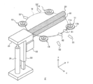
- FIG. 1 is a schematic perspective view of a substrate cleaning apparatus 2 according to a first embodiment.
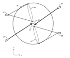
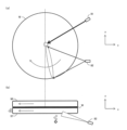
- FIG. 5 is a diagram illustrating a cleaning liquid supply area from cleaning liquid supply nozzles 51 and 52.
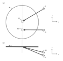
- FIG. 4 is a diagram schematically showing a cleaning process when the rotation direction of the substrate W in the liquid landing area and the supply direction of the cleaning liquid match.
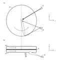
- FIG. 3 is a diagram schematically showing a cleaning process when the rotational direction of the substrate W in the liquid landing area and the supply direction of the cleaning liquid do not match.
- FIG. 1 is a block diagram showing a schematic configuration of a substrate processing apparatus 100.
- FIG. 1 is a schematic perspective view of a substrate cleaning apparatus 2 according to a first embodiment.
- FIG. 5 is a diagram illustrating a cleaning liquid supply area from cleaning liquid supply nozzles 51 and 52.
- FIG. 4 is a diagram schematically showing a cleaning process when the rotation direction of the substrate
- FIG. 3 is a diagram showing the results of an experiment in which the cleaning performance on the lower surface of the substrate W was compared between the substrate cleaning apparatus 2 according to the first embodiment and a substrate cleaning apparatus as a comparative example.
- 3 is a schematic perspective view of a substrate cleaning device 2 that is a modification of the substrate cleaning device 2 in FIG. 2.
- FIG. 4 is a diagram illustrating cleaning liquid supply areas from cleaning liquid supply nozzles 51, 52, 51', and 52'.
- FIG. 5 is a diagram illustrating a cleaning liquid supply area from single tube nozzles 51 and 53.
- FIG. 7 is a diagram showing the results of an experiment in which the cleaning performance on the lower surface of the substrate W was compared between the substrate cleaning apparatus 2' according to the second embodiment and the substrate cleaning apparatus as a comparative example.
- FIG. 4 is a diagram illustrating cleaning liquid supply areas from single tube nozzles 51, 53, 51', and 53'.
- FIG. 3 is a schematic perspective view of a substrate cleaning apparatus 3 according to a third embodiment.
- FIG. 3 is a diagram schematically showing a cleaning process when the rotational direction of the substrate W in the liquid landing area and the supply direction of the cleaning liquid do not match.
- FIG. 4 is a diagram schematically showing a cleaning process when the rotation direction of the substrate W in the liquid landing area and the supply direction of the cleaning liquid match.
- FIG. 7 is a diagram illustrating a desirable pure water supply area from a single pipe nozzle 81.
- FIG. 2 is a diagram experimentally showing the relationship between the area where pure water lands and cleaning power.
- FIG. 7 is a diagram illustrating a desirable pure water supply area from a spray nozzle 82.
- FIG. 7 is a diagram illustrating a desirable arrangement of pure water supply nozzles 81 and 82 when viewed from vertically above.
- FIG. 7 is a diagram showing the results of an experiment in which the cleaning performance on the lower surface of the substrate W was compared between the substrate cleaning apparatus 3 according to the third embodiment and the substrate cleaning apparatus as a comparative example.
- 11 is a schematic perspective view of a substrate cleaning device 3 that is a modification of the substrate cleaning device 3 of FIG. 10.
- FIG. . FIG. 7 is a diagram showing the results of an experiment in which the cleaning performance on the lower surface of the substrate W was compared between the substrate cleaning apparatus 3 according to the fourth embodiment and the substrate cleaning apparatus as a comparative example.
- FIG. 1 is a block diagram showing a schematic configuration of a substrate processing apparatus 100.
- the substrate processing apparatus 100 includes a substrate polishing apparatus 1 and substrate cleaning apparatuses 2 and 3.
- the type, shape, and size of the substrate to be processed are not particularly limited, and may be, for example, a circular semiconductor wafer with a diameter of 300 mm.
- the substrate polishing apparatus 1 polishes the surface and/or bevel of the substrate using a polishing liquid. Defects such as polishing liquid and polishing debris are attached to the upper surface (front surface) and lower surface (back surface) of the substrate after polishing. Since a known device may be used as the substrate polishing device 1, a description thereof will be omitted.
- the substrate cleaning device 2 scrubs and cleans the top and bottom surfaces of the substrate polished by the substrate polishing device 1 using a cleaning liquid to remove dust.
- the cleaning liquid may be a chemical solution or deionized water (DIW). Cleaning liquid remains on the top and bottom surfaces of the substrate after cleaning.
- DIW deionized water
- the substrate cleaning device 3 uses pure water to clean the top and bottom surfaces of the substrate cleaned by the substrate cleaning device 2, and replaces the remaining cleaning liquid with pure water.
- the configuration of the substrate cleaning apparatus 3 will be described in the third and fourth embodiments.
- the substrate processing apparatus 100 includes a transport device that transports the substrate to be processed from a load port (not shown) to the substrate polishing device 1, and a substrate cleaning device 2 that transports the substrate polished by the substrate polishing device 1. and a transport device that transports the substrate cleaned by the substrate cleaning device 2 to the substrate cleaning device 3. Further, the substrate processing apparatus 100 may include a substrate drying device that dries the substrate after cleaning.
- FIG. 2 is a schematic perspective view of the substrate cleaning apparatus 2 according to the first embodiment.
- the substrate cleaning apparatus 2 includes substrate rotation mechanisms 11 to 14, scrub cleaning members 21 and 22, rotation mechanisms 31 and 32, a guide rail 33, a lifting drive mechanism 34, and cleaning liquid supply nozzles 41 and 42 for the upper surface. , cleaning liquid supply nozzles 51 and 52 for the lower surface.
- the substrate rotation mechanisms 11 to 14 hold and rotate the substrate W.
- the substrate rotation mechanisms 11 to 14 hold the substrate W in a horizontal direction and rotate it within a horizontal plane.
- the rotation speed is, for example, 50 to 500 rpm.
- the substrate rotation mechanism 11 is a roller composed of a holding part 11a and a shoulder part (supporting part) 11b.
- the diameter of the shoulder portion 11b is larger than the diameter of the holding portion 11a, and the holding portion 11a is provided on the shoulder portion 11b.
- the substrate rotation mechanisms 12 to 14 also have the same configuration as the substrate rotation mechanism 11.
- the substrate rotation mechanisms 11 to 14 can be moved toward and away from each other by a drive mechanism (for example, an air cylinder) not shown. Since the substrate rotation mechanisms 11 to 14 are close to each other, the holding parts 11a to 14a can hold the substrate W substantially horizontally. Further, at least one of the substrate rotation mechanisms 11 to 14 is configured to be rotationally driven by a rotation mechanism (not shown), and thereby the substrate W can be rotated within a horizontal plane.
- the surface of the substrate facing upward in the vertical direction when held by the substrate rotation mechanisms 11 to 14 is referred to as the upper surface of the substrate W
- the surface of the substrate facing downward in the vertical direction is referred to as the lower surface of the substrate W.
- devices are formed on the upper surface of the substrate W.
- the scrub cleaning member 21 contacts the top surface of the substrate W and scrubs the top surface of the substrate W.
- the scrub cleaning member 21 is a roll type made of sponge or the like, and is arranged so as to extend horizontally from the edge of the substrate W through the center to the opposite edge.
- the scrub cleaning member 21 is rotated by the rotation mechanism 31 with the longitudinal direction of the scrub cleaning member 21 as an axis. Further, the rotation mechanism 31 is attached to a guide rail 33 that guides its vertical movement, and is supported by an elevating drive mechanism 34. The rotation mechanism 31 and the scrub cleaning member 21 are moved in the vertical direction along the guide rail 33 by the elevating drive mechanism 34 .
- the scrub cleaning member 22 is arranged below the scrub cleaning member 21, contacts the lower surface of the substrate W, and scrubs the lower surface of the substrate W.
- the scrubbing member 22 is a roll type made of sponge or the like, and is arranged so as to extend horizontally from the edge of the substrate W through the center to the opposite edge.
- the scrub cleaning member 22 is rotated by the rotation mechanism 32 with the longitudinal direction of the scrub cleaning member 22 as an axis.
- illustration of an elevating drive mechanism and the like is omitted, like the scrub cleaning member 21, the rotation mechanism 32 and the scrub cleaning member 22 also move in the vertical direction.
- the cleaning liquid supply nozzles 41 and 42 are arranged above the substrate W and supply the cleaning liquid to the upper surface of the substrate W.
- the cleaning liquid supply nozzle 41 is a single pipe nozzle, and supplies the cleaning liquid to the vicinity of the center of the upper surface of the substrate W.
- the cleaning liquid supply nozzle 42 is also a single pipe nozzle, and supplies the cleaning liquid to a position different from the vicinity of the center of the upper surface of the substrate W (for example, between the center and the edge).
- the tip diameter of the cleaning liquid supply nozzles 41 and 42 may be 1.0 mm in diameter. However, there are no restrictions on the type or number of cleaning liquid supply nozzles 41 and 42, and they may be omitted depending on the case.
- the cleaning liquid supply nozzles 51 and 52 are arranged below the substrate W and supply the cleaning liquid to the lower surface of the substrate W.
- the cleaning liquid supply nozzle 51 is a single tube nozzle (hereinafter sometimes referred to as "single tube nozzle 51").
- the radius of the single tube nozzle 51 is, for example, 0.5 to 3 mm.
- the cleaning liquid supply nozzle 52 is a spray nozzle (hereinafter sometimes referred to as "spray nozzle 52").
- the spread angle is, for example, 50 to 150 degrees.
- the single-tube nozzle 51 continuously supplies large droplets to a narrow area on the lower surface of the substrate W, so the hitting force is strong.
- the spray nozzle 52 supplies small droplets discontinuously and dispersed to a wide area on the lower surface of the substrate W, the striking force is weak.
- the cleaning liquid used in the present substrate cleaning apparatus 2 may be a chemical solution or pure water.
- the chemical solution may be an organic solvent or a heated one, and the pure water may be ultrasonic water or contain microbubbles.
- the cleaning liquid from one nozzle may be a chemical liquid, and the cleaning liquid from another nozzle may be pure water.
- the cleaning liquid from all nozzles may be a chemical liquid, or the cleaning liquid from all nozzles may be pure water.
- the flow rate balance of the cleaning liquid supplied from the cleaning liquid supply nozzles 51 and 52 is arbitrary, for example, both are 500 ml/min.
- the total flow rate of the cleaning liquid supplied from the cleaning liquid supply nozzles 51 and 52 is, for example, 500 to 4000 ml/min.
- the cleaning liquid supply nozzles 51 and 52 may be arranged horizontally shifted or vertically shifted.
- the center of the held substrate W is the origin
- the direction in which the scrub cleaning members 21 and 22 extend is the y direction (the side where the rotation mechanism 31 is provided is the negative direction)
- the y direction in the horizontal plane is the direction perpendicular to the direction
- the x direction the side where the cleaning liquid supply nozzles 51 and 52 are provided is positive
- the vertical direction is the z direction (the upward direction is positive).
- the cleaning liquid supply nozzles 51 and 52 are arranged in a region where x>0 and z ⁇ 0.
- FIG. 3 is a diagram illustrating the cleaning liquid supply area from the cleaning liquid supply nozzles 51 and 52.
- FIG. 3(a) corresponds to a view of the substrate W viewed from below in the +z direction, and FIG. This corresponds to a view seen from the side in the +y direction (however, the scrubbing member 22 is omitted).
- the cleaning liquid from the single tube nozzle 51 is applied to a narrow liquid landing area that includes the vicinity of the center of the substrate W ("near the center” preferably includes the center, but does not have to include the center).
- A1 is supplied.
- the area A1 where the cleaning liquid from the single pipe nozzle 51 lands can be said to be near the origin.
- the cleaning liquid from the spray nozzle 52 is supplied from near the center of the substrate W to a wide liquid landing area A2 covering the edge while spreading in a fan shape or a cone shape.
- the area A2 where the cleaning liquid from the spray nozzle 52 lands is an area where x ⁇ 0 and y ⁇ 0.
- the direction from the spray nozzle 52 toward the longitudinal center of the liquid-receiving area A2 is referred to as the cleaning liquid supply direction of the spray nozzle 52. This cleaning liquid supply direction is approximately the -x direction.
- FIG. 4A is a diagram schematically showing the state of cleaning when the rotation direction of the substrate W in the liquid landing area and the supply direction of the cleaning liquid match, and FIG. (b) corresponds to a view when the substrate W is viewed from the side in the +y direction.
- the substrate W is rotating clockwise when viewed from below.
- the tangential direction of the rotational direction of the substrate W in the area where the cleaning liquid from the spray nozzle 52 lands is the ⁇ x direction.
- the cleaning liquid supply direction from the cleaning liquid supply nozzles 51 and 52 is also in the ⁇ x direction. In this way, the tangential direction of the rotational direction of the substrate W in the liquid landing area and the cleaning liquid supply direction match (both in the -x direction).
- the rotation direction of the scrub cleaning member 21 is counterclockwise when viewed from the side in the +y direction, and the rotation direction of the scrub cleaning member 22 is clockwise (that is, the direction of rotation of the scrub cleaning member 22 is clockwise when viewed from the side in the +y direction).
- the tangential direction of the rotation direction of the scrub cleaning members 21, 22 and the tangential direction of the rotation direction of the substrate W are opposite to each other. ), but reverse rotation is also possible.
- cleaning liquid layers 91 and 92 are formed on the upper and lower surfaces of the substrate W, respectively, and flow in the same direction as the tangential direction of the rotation direction of the substrate W (that is, the -x direction).
- the flow of the cleaning liquid existing at a distance of about 10 ⁇ m or less from the substrate W is particularly slow at about 20 mm/s (estimated value). It is called the viscous low layer.
- dust such as polishing liquid and polishing debris is attached to the upper and lower surfaces of the substrate W. This dust is scraped off from the upper and lower surfaces of the substrate W by scrubbing members 21 and 22.
- FIG. 4B is a diagram schematically showing how cleaning is performed when the rotation direction of the substrate W in the liquid landing area and the supply direction of the cleaning liquid do not match, and FIG. 4(a) shows the substrate W from below in +z direction. (b) corresponds to a view when the substrate W is viewed from the side in the +y direction.
- the substrate W is rotating counterclockwise when viewed from below.
- the tangential direction of the rotational direction of the substrate W in the area where the cleaning liquid from the spray nozzle 52 lands is the + direction.
- the cleaning liquid supply direction from the cleaning liquid supply nozzles 51 and 52 is the ⁇ x direction. In this way, the tangential direction of the rotational direction of the substrate W in the liquid landing area does not match the cleaning liquid supply direction.
- the rotation direction of the scrub cleaning member 21 is counterclockwise when viewed from the side in the +y direction
- the rotation direction of the scrub cleaning member 22 is clockwise (that is, the direction of rotation of the scrub cleaning member 22 is clockwise when viewed from the side in the +y direction).
- the tangential direction of the rotation direction of the scrub cleaning members 21 and 22 and the tangential direction of the rotation direction of the substrate W are in the same direction. ), but reverse rotation is also possible.
- the flow of the cleaning liquid layer 92 is in the +x direction, and the rotation direction of the scrub cleaning member 22 is also clockwise, so most of the scraped dirt 95 is flowed in the +x direction.
- the cleaning liquid supply direction from the spray nozzle 52 is the -x direction, which is opposite to the flow of the cleaning liquid layer 92 (+x direction). Since the cleaning liquid from the spray nozzle 52 has a weak striking force and has fine droplets, it is repelled by the cleaning liquid layer 92 and falls downward. At this time, since the cleaning liquid falls together with the dust 95, the dust 95 can be efficiently discharged downward.
- FIG. 5 is a diagram showing the results of an experiment in which the cleaning performance on the lower surface of the substrate W was compared between the substrate cleaning apparatus 2 according to the first embodiment and a substrate cleaning apparatus as a comparative example.
- a substrate cleaning apparatus as a comparative example is obtained by replacing the cleaning liquid supply nozzles 51 and 52 of the substrate cleaning apparatus 2 according to the first embodiment with comb-shaped nozzles.
- the comb-shaped nozzle is a rod-shaped tube that extends parallel to the scrub cleaning member 22 and has about 10 to 15 holes, and the cleaning liquid is supplied to the entire lower surface of the substrate W from each hole.
- the substrate cleaning apparatus 2 according to the first embodiment and the substrate cleaning apparatus of the comparative example were made to have the same conditions such as the amount of cleaning liquid supplied per unit time, the rotation speed and rotation direction of the substrate W. .
- the vertical axis in FIG. 5 is the number of defects normalized in the comparative example after cleaning for a certain period of time.
- the substrate cleaning apparatus 2 according to the present embodiment that uses a single pipe nozzle 51 and a spray nozzle 52 instead of a comb-shaped nozzle, whether the cleaning liquid is an alkaline chemical or pure water, the substrate W We were able to reduce the number of debris remaining on the back side of the paper by approximately 40%.
- scrub cleaning is performed while supplying cleaning liquid to the lower surface of the substrate W from the single pipe nozzle 51 and the spray nozzle 52. Thereby, dust such as polishing liquid attached during substrate polishing can be efficiently removed from the lower surface of the substrate W.
- FIG. 6A is a schematic perspective view of a substrate cleaning apparatus 2 that is a modification of the substrate cleaning apparatus 2 of FIG. 51' and spray nozzle 52' may be omitted).
- FIG. 6B is a diagram illustrating the cleaning liquid supply areas from the cleaning liquid supply nozzles 51, 52, 51', and 52' in that case, and corresponds to a diagram when the substrate W is viewed from below in the +z direction (however, (The scrub cleaning member 22 is omitted).
- the single-tube nozzle 51' is located below the substrate W, and is arranged at a position symmetrical to the single-tube nozzle 51 with respect to the center of the substrate W when viewed from vertically above. It is desirable that the single tube nozzle 51 and the single tube nozzle 51' be on the same plane.
- the spray nozzle 52' is arranged below the substrate W, and at a position that is point symmetrical to the spray nozzle 52 with respect to the center of the substrate W when viewed from vertically above.
- spray nozzle 52 and spray nozzle 52' are coplanar.
- the cleaning liquid from the single tube nozzle 51 is supplied to the liquid landing area A1 near the center of the substrate W.
- the cleaning liquid from the single tube nozzle 51' is supplied to the liquid landing area A1' near the center of the substrate W. It is desirable that the liquid landing area A1 and the liquid landing area A1' be at different positions. However, it is desirable that any of them include the vicinity of the center of the substrate W.
- the cleaning liquid from the spray nozzle 52 is supplied from the center of the substrate W to the liquid landing area A2 covering the edge.
- the liquid landing area A2 is an area where x ⁇ 0 and y ⁇ 0.
- the cleaning liquid from the spray nozzle 52' is supplied to the liquid landing area A2' covering the edge of the substrate W from the center thereof. It is desirable that the liquid landing area A2' be an area where x ⁇ 0 and y>0.
- the second embodiment is a modification of the substrate cleaning apparatus 2 described in the first embodiment.
- differences from the first embodiment will be mainly explained.
- a substrate cleaning apparatus 2' according to the second embodiment is obtained by replacing the spray nozzle 52 in the substrate cleaning apparatus 2 according to the first embodiment with a single tube nozzle 53.
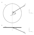
- FIG. 7 is a diagram illustrating the cleaning liquid supply area from the single tube nozzles 51 and 53. FIG. This corresponds to a view seen from the side in the +y direction.
- the cleaning liquid from the single tube nozzle 51 is supplied to a narrow liquid landing area A1 that includes (or is near the center of) the center of the substrate W.
- the cleaning liquid from the single tube nozzle 53 is supplied to a narrow liquid landing area A3 between the center and the edge of the substrate W near the scrub cleaning member 22 (omitted in FIG. 7).
- the cleaning liquid supply direction from the single pipe nozzle 53 may be perpendicular to the scrub cleaning member 22.
- FIG. 8 is a diagram showing the results of an experiment in which the cleaning performance on the lower surface of the substrate W was compared between the substrate cleaning apparatus 2' according to the second embodiment and a substrate cleaning apparatus as a comparative example.
- the comparison method was the same as that shown in FIG. 7, and a comb-shaped nozzle was used in the comparative example.
- the cleaning liquid is a chemical or pure water, the cleaning liquid remains on the back surface of the substrate W. We were able to reduce the amount of garbage produced by approximately 50%.
- the comb-shaped nozzle supplies cleaning liquid from 10 to 15 holes, when the amount of cleaning liquid supplied per unit time is equal, the single pipe nozzles 51 and 53 have a stronger cleaning liquid impact, and the cleaning liquid layer has a stronger impact force ( horizontal propulsion) is high. Therefore, the force for discharging dust in the horizontal direction increases.
- the single tube nozzle 51 can supply the cleaning liquid more intensively to the center of the substrate W. Therefore, when the single tube nozzle 51 is used, it is possible to suppress a decrease in cleaning power near the center of the substrate W, where the effect of rotation becomes smaller.
- the effect of dropping dirt downward is relatively small, but the cleaning effect is higher than in the comparative example using a comb-shaped nozzle.
- FIG. 9 is a diagram illustrating the cleaning liquid supply area from the single pipe nozzles 51, 53, 51', and 53' in that case, and corresponds to the diagram when the substrate W is viewed from below in the +z direction (however, the scrub cleaning (The member 22 is omitted).
- the single-tube nozzle 51' is located below the substrate W, and is arranged at a position symmetrical to the single-tube nozzle 51 with respect to the center of the substrate W when viewed from vertically above.
- the single tube nozzle 51 and the single tube nozzle 51' may be on the same plane.
- the single-tube nozzle 53' is located below the substrate W, and is located at a point symmetrical to the single-tube nozzle 53 with respect to the center of the substrate W when viewed from vertically above.
- the single tube nozzle 53 and the single tube nozzle 53' may be on the same plane.
- the cleaning liquid from the single tube nozzle 51 is supplied to the liquid landing area A1 near the center of the substrate W.
- the cleaning liquid from the single tube nozzle 51' is supplied to the liquid landing area A1' near the center of the substrate W. It is desirable that the liquid landing area A1' and the liquid landing area A1' are different areas. However, it is desirable that one of them includes the center of the substrate W.
- the cleaning liquid from the single tube nozzle 53 is supplied to the liquid landing area A3 between the center and the edge of the substrate W.
- the cleaning liquid from the single tube nozzle 53' is supplied to the liquid landing area A3' between the center and the edge of the substrate W.
- the substrate cleaning apparatus 3 of FIG. 1 replaces the cleaning liquid remaining on the surface of the substrate W, which was used in the cleaning in the substrate cleaning device 2, with pure water.
- FIG. 10 is a schematic perspective view of the substrate cleaning apparatus 3 according to the third embodiment.
- This substrate cleaning apparatus 4 includes substrate rotation mechanisms 61 to 64, deionized water supply nozzles 71 and 72 for the upper surface, and deionized water supply nozzles 81 and 82 for the lower surface. Note that, compared to the substrate cleaning apparatus 2 shown in FIG. 2, the scrub cleaning members 21 and 22, the rotation mechanisms 31 and 32 related thereto, the guide rail 33, and the elevation drive mechanism 34 are not necessary. The rest is the same as the substrate cleaning apparatus 2 shown in FIG.
- the pure water supply nozzle 81 for the lower surface is a single pipe nozzle (hereinafter sometimes referred to as “single pipe nozzle 81"), and the pure water supply nozzle 82 is a spray nozzle (hereinafter referred to as “single pipe nozzle 81"). (Sometimes referred to as “spray nozzle 82.”)
- the contact areas of the pure water supplied from these nozzles are similar to those shown in FIG.
- FIG. 11A is a diagram schematically showing how cleaning is performed when the rotational direction of the substrate W in the liquid landing area and the supply direction of the cleaning liquid do not match, and FIG. (b) corresponds to a view when the substrate W is viewed from the side in the +y direction.
- the substrate W is rotating counterclockwise when viewed from below.
- the tangential direction of the rotational direction of the substrate W in the landing area of the cleaning liquid from the spray nozzle 82 (the area where x ⁇ 0 and y ⁇ 0) is the + direction.
- the pure water supply direction from the pure water supply nozzles 81 and 82 is the ⁇ x direction. In this way, the tangential direction of the rotational direction of the substrate W in the liquid landing area does not match the direction of pure water supply.
- the flow of the cleaning liquid layer 97 is in the +x direction.
- the pure water supply direction from the spray nozzle 82 is the ⁇ x direction, which is opposite to the flow of the cleaning liquid layer 97 (+x direction).
- the pure water from the spray nozzle 82 collides over a wide range while dispersing small droplets discontinuously, and the momentum (mass) of the droplets is small. Therefore, the flow velocity in the horizontal direction after the droplets collide with the cleaning liquid layer 97 is low, and the droplets are repelled by the cleaning liquid layer 97 and fall downward. At this time, since the pure water falls together with the cleaning liquid layer 97, the cleaning liquid layer 97 can be efficiently discharged downward.
- the spray nozzle 82 is more desirable.
- the pure water that has landed on the substrate W falls due to gravity before it can sufficiently spread. Therefore, the cleaning liquid layer 97 cannot be removed efficiently in areas of the substrate W that are away from the liquid landing area.
- the spray nozzle 82 can supply pure water to a wide area, and the liquid landing area itself can be widened, so the cleaning liquid can be spread over a wide area without falling due to gravity before the pure water has spread sufficiently. The layer 97 can be removed efficiently.
- the striking force of the pure water is strong, so the pure water tends to flow backward along the substrate W on the bottom surface of the substrate W, causing stagnation of the liquid and removing the pure water from the cleaning liquid layer 97. Difficult to replace with water.
- the spray nozzle 82 supplies pure water with a weak striking force, the water does not flow backward along the substrate W, but is easily repelled and falls downward. Thereby, the cleaning liquid layer 97 can be efficiently removed downward.
- the reason why not only the spray nozzle 82 but also the single pipe nozzle 81 is provided is as follows. Since the cleaning liquid from the spray nozzle 82 lands on a wide area, less cleaning liquid is supplied to the center of the substrate W. Since the rotational speed at the center of the substrate W is relatively low, the liquid flow is poor, and if the amount of cleaning liquid is small, the cleaning power may not be sufficient. Therefore, in order to supply sufficient cleaning liquid to the center of the substrate W, the cleaning liquid is supplied toward the center of the substrate W from the single tube nozzle 81.
- FIG. 11B is a diagram schematically showing the state of cleaning when the rotation direction of the substrate W in the liquid landing area and the supply direction of the cleaning liquid match, and FIG. (b) corresponds to a view when the substrate W is viewed from the side in the +y direction.
- the substrate W is rotating clockwise when viewed from below.
- the tangential direction of the rotational direction of the substrate W in the area where the cleaning liquid from the spray nozzle 82 lands is the ⁇ x direction.
- the pure water supply direction from the pure water supply nozzles 81 and 82 is also in the ⁇ x direction.
- the cleaning liquid layer 97 is removed horizontally by the rotation of the substrate W, and the cleaning liquid layer 97 is removed downward by the pure water from the pure water supply nozzles 81 and 82.
- the cleaning liquid layer 97 can be replaced with pure water more efficiently.
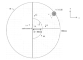
- FIG. 12 is a diagram illustrating a desirable pure water supply area from the single tube nozzle 81.
- FIG. 12(a) corresponds to a view of the substrate W viewed from below, and
- FIG. Corresponds to the diagram seen.
- the single tube nozzle 81 supplies pure water so that the liquid landing area falls within a region B1 of 0 ⁇ x ⁇ D, which is in front of the center of the substrate W (single tube nozzle 81 side). It is desirable to do so. This is because if the liquid landing area is in the area where x ⁇ 0, the cleaning power at the center of the substrate W where the rotation speed is low will be insufficient. Also, if the liquid landing area is too close to the edge of the substrate W (an area where x is too large) and the single tube nozzle 81 needs to be directed upward, the ability to discharge the cleaning liquid layer 97 formed on the lower surface of the substrate W is also provided. This is because the amount decreases.
- FIG. 13 is a diagram experimentally showing the relationship between the area where pure water lands and the cleaning power.
- the position indicated as "nozzle position" is the arrangement position of the single tube nozzle 81, and six small circles indicate the liquid landing area.
- the numerical value indicates the pH after pure water is supplied to each liquid landing area under certain conditions on the lower surface of the substrate W on which a layer of alkaline cleaning liquid is formed.
- the pH after pure water is supplied is 7.4, and the alkaline cleaning liquid has not been sufficiently removed.
- the pH after supplying pure water is 7.8 or 8.0, and the alkaline cleaning liquid is not sufficiently removed.
- the pH after supplying pure water is 7.0, and the alkaline cleaning liquid has been sufficiently removed.
- D is preferably 50 mm or less, more preferably 30 mm or less. Generally, it is desirable that D be 16% or less of the diameter of the substrate W.
- the angle ⁇ between the substrate W and the direction of supply of pure water (hereinafter referred to as "vertical angle") is preferably 10 degrees to 60 degrees, more preferably 20 degrees to 40 degrees, and 30 degrees to 35 degrees. degree is even more desirable. This is because if the vertical angle ⁇ is too large (close to 90 degrees), the ability to discharge the cleaning liquid layer 97 in the horizontal direction will be reduced. Further, if the vertical angle ⁇ is too small (less than 10 degrees), the ability to discharge the cleaning liquid layer 97 downward will be reduced.
- FIG. 14 is a diagram experimentally showing the relationship between vertical angle and cleaning power. It shows the change over time in the residual rate of the cleaning liquid layer remaining on the lower surface of the substrate W when the vertical angle is 20 degrees, 30 degrees, 40 degrees, and 60 degrees. This is particularly noticeable between 1 and 1.25 seconds, but it can be seen that it is desirable that the vertical angle is between 20 degrees and 40 degrees, and more preferably 30 degrees.
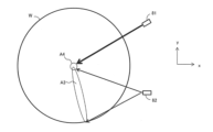
- FIG. 15 is a diagram illustrating a desirable pure water supply area from the spray nozzle 82, and corresponds to a diagram when the substrate W is viewed from below.
- the landing area A3 of pure water supplied from the spray nozzle 82 at least partially overlaps the landing area A4 of pure water supplied from the single tube nozzle 81. Furthermore, the liquid landing area A3 reaches the edge of the substrate W. This is because if the pure water does not reach the edge, the efficiency of replacing the cleaning liquid layer 97 at the edge with pure water decreases.
- the angle (vertical angle) between the substrate W and the direction of supply of pure water from the spray nozzle 82 is preferably 15 degrees to 60 degrees, more preferably 20 degrees to 40 degrees, similarly to the single tube nozzle 81. , more preferably 30 to 35 degrees.
- FIG. 16 is a diagram illustrating a desirable arrangement of the pure water supply nozzles 81 and 82 when viewed from vertically above.
- the distance between the line L connecting the single tube nozzle 81 and the spray nozzle 82 and the center of the substrate W is preferably 300 mm or less.
- the angle ⁇ between the reference line M and the line connecting the single tube nozzle 81 and the center of the substrate W is The angle is preferably 0 degrees to 75 degrees, more preferably 15 degrees to 45 degrees.
- the angle ⁇ between the reference line M and the line connecting the spray nozzle 82 and the center of the substrate W is preferably between 0 degrees and -75 degrees, and preferably between -15 degrees and -45 degrees. More desirable. This is because the pure water from the single pipe nozzle 81 and the pure water from the spray nozzle 82 are mixed, and the cleaning liquid layer 97 near the center of the substrate W is efficiently discharged in the horizontal direction.
- the single tube nozzle 81 preferably has the above-mentioned angle ⁇ of a certain degree.
- cleaning is performed by supplying pure water to the lower surface of the substrate W from the single tube nozzle 81 and the spray nozzle 82. Thereby, cleaning liquid remaining during substrate cleaning by the substrate cleaning apparatus 2 can be efficiently removed from the lower surface of the substrate W.
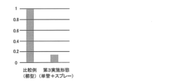
- FIG. 17 is a diagram showing the results of an experiment in which the cleaning performance on the lower surface of the substrate W was compared between the substrate cleaning apparatus 3 according to the third embodiment and a substrate cleaning apparatus as a comparative example.
- the vertical axis represents the time required to remove the cleaning liquid layer remaining on the lower surface of the substrate W, normalized to the comparative example.
- the comparison method was the same as that in FIG. 7, and a comb-shaped nozzle was used as a comparative example.
- the substrate cleaning apparatus 3 of this embodiment which uses a single pipe nozzle 81 and a spray nozzle 82 instead of a comb-shaped nozzle, was able to reduce the time required to remove the cleaning liquid to less than 20%.
- the substrate cleaning apparatus 3 may have an additional single tube nozzle 81' and a spray nozzle 82' (see FIG. 18. However, one of the single tube nozzle 81' and the spray nozzle 82' may be omitted).
- the fourth embodiment is a modification of the substrate cleaning apparatus 3 described in the third embodiment.
- differences from the third embodiment will be mainly explained.
- a substrate cleaning apparatus 3' according to the fourth embodiment is obtained by replacing the spray nozzle 82 in the substrate cleaning apparatus 3 according to the third embodiment with a single tube nozzle.
- the pure water landing area in this case is similar to that shown in FIG.
- FIG. 19 shows the results of an experiment on cleaning performance in this case.
- the vertical axis represents the time required to remove the cleaning liquid layer remaining on the lower surface of the substrate W, normalized to the comparative example.
- the comparison method is the same as in FIG. As shown in the figure, even when the spray nozzle was replaced with a single pipe nozzle, the time required to remove the cleaning liquid could be reduced by about 70% compared to a comb-shaped nozzle. Note that, similarly to FIG. 9, an additional single tube nozzle may be provided (however, one of the single tube nozzles 51' and 53' in FIG. 9 may be omitted).
- the substrate cleaning device 2 and the substrate cleaning device 3 are separate devices.
- the cleaning liquid used in the substrate cleaning device 2 is pure water
- the substrate cleaning devices 2 and 3 may be integrated.
- pure water is supplied to the upper and lower surfaces of the substrate to remove dust generated during polishing.
- pure water is supplied to the upper and lower surfaces of the substrate to remove the purified water remaining on the upper and lower surfaces of the substrate. Remove.
- Substrate processing apparatus 1 Substrate polishing apparatus 2, 3 Substrate cleaning apparatus 11 to 14, 61 to 64 Substrate rotation mechanism 21, 22 Scrub cleaning member 31, 32 Rotation mechanism 33 Guide rail 34 Lifting drive mechanism 41, 42, 71, 72 Cleaning liquid Supply nozzles 51, 51', 53, 53', 81, 81' Single tube nozzles 52, 52', 82 Spray nozzles 91, 92, 96, 97 Cleaning liquid layer 93-95 Dust
Landscapes
- Engineering & Computer Science (AREA)
- Mechanical Engineering (AREA)
- Cleaning Or Drying Semiconductors (AREA)
- Mechanical Treatment Of Semiconductor (AREA)
Abstract
Description
[1]
洗浄対象となる基板の下面をスクラブ洗浄する第1スクラブ洗浄部材と、
前記基板の下面の中心近傍に洗浄液を供給する第1単管ノズルと、
前記基板の下面に洗浄液を供給する第1スプレーノズルと、を備える基板洗浄装置が提供される。
上記[1]に記載の基板洗浄装置において、
前記第1スプレーノズルから供給される洗浄液の着液領域は、前記基板の中心近傍から前記基板のエッジ近傍をカバーするのが望ましい。
上記[1]または[2]に記載の基板洗浄装置において、
鉛直上方から見て前記基板の中心に対して前記第1単管ノズルと点対称となる位置に配置され、前記基板の下面の中心近傍であって、前記第1単管ノズルからの洗浄液供給領域とは異なる領域に洗浄液を供給する第2単管ノズルと、
鉛直上方から見て前記基板の中心に対して前記第1スプレーノズルと点対称となる位置に配置され、前記基板の下面に洗浄液を供給する第2スプレーノズルと、のうち少なくとも一方を備えるのが望ましい。
[4]
洗浄対象となる基板の下面をスクラブ洗浄する第1スクラブ洗浄部材と、
前記基板の下面の中心近傍に洗浄液を供給する第1単管ノズルと、
前記基板の下面の中心近傍とは異なる領域に洗浄液を供給する第2単管ノズルと、を備える基板洗浄装置が提供される。
上記[4]に記載の基板洗浄装置において、
鉛直上方から見て前記基板の中心に対して前記第1単管ノズルと点対称となる位置に配置され、前記基板の下面の中心近傍であって、前記第1単管ノズルからの洗浄液供給領域とは異なる領域に洗浄液を供給する第3単管ノズルと、
鉛直上方から見て前記基板の中心に対して前記第2単管ノズルと点対称となる位置に配置され、前記基板の下面の中心近傍とは異なる領域に洗浄液を供給する第4単管と、のうち少なくとも一方を備えるのが望ましい。
上記[1]乃至[5]のいずれかに記載の基板洗浄装置において、
前記基板の上面をスクラブ洗浄する第2スクラブ洗浄部材と、
前記基板の上面の中心近傍に洗浄液を供給する第3単管ノズルと、
前記基板の上面の中心近傍とは異なる領域に洗浄液を供給する第4単管ノズルと、を備えるのが望ましい。
[7]
洗浄対象となる基板の下面の中心近傍に純水を供給する、単管ノズルである第1ノズルと、
前記基板の下面に純水を供給する、スプレーノズルである第2ノズルと、を備える基板洗浄装置が提供される。
上記[7]に記載の基板洗浄装置において、
鉛直上方から見て前記基板の中心に対して前記第1ノズルと点対称となる位置に配置され、前記基板の下面の中心近傍であって、前記第1ノズルからの純水供給領域とは異なる領域に純水を供給する、単管ノズルである第3ノズルと、
鉛直上方から見て前記基板の中心に対して前記第2ノズルと点対称となる位置に配置され、前記基板の下面に純水を供給する、スプレーノズルである第4ノズルと、のうち少なくとも一方を備えるのが望ましい。
[9]
洗浄対象となる基板の下面の中心近傍に純水を供給する、単管ノズルである第1ノズルと、
前記基板の下面の中心近傍とは異なる領域に純水を供給する、単管ノズルである第2ノズルと、を備える基板洗浄装置が提供される。
上記[9]に記載の基板洗浄装置において、
鉛直上方から見て前記基板の中心に対して前記第1ノズルと点対称となる位置に配置され、前記基板の下面の中心近傍であって、前記第1ノズルからの純水供給領域とは異なる領域に純水を供給する、単管ノズルである第3ノズルと、
鉛直上方から見て前記基板の中心に対して前記第2ノズルと点対称となる位置に配置され、前記基板の下面の中心近傍とは異なる領域に純水を供給する、単管ノズルである第4ノズルと、のうち少なくとも一方を備えるのが望ましい。
上記[7]乃至[10]のいずれかに記載の基板洗浄装置において、
前記基板を回転するように構成された基板回転機構を備え、
前記第1ノズルから供給される純水の供給方向と、前記第2ノズルから供給される純水の着液領域における前記基板の回転方向の接線方向は、逆方向であってよい。
上記[7]乃至[10]のいずれかに記載の基板洗浄装置において、
前記基板を回転するように構成された基板回転機構を備え、
前記第1ノズルから供給される純水の供給方向と、前記第2ノズルから供給される純水の着液領域における前記基板の回転方向の接線方向は、同方向であってよい。
上記[12]に記載の基板洗浄装置において、
前記基板と、前記第1ノズルから供給される純水の供給方向と、がなす角は、10~60度であるのが望ましい。
[14]
研磨液を用いて基板を研磨する基板研磨装置と、
前記基板研磨装置による研磨後の基板を洗浄液を用いてスクラブ洗浄する、上記[1]乃至[6]のいずれかに記載の基板洗浄装置である第1基板洗浄装置と、
前記第1基板洗浄装置による洗浄後の基板を純水を用いて洗浄する、上記[7]乃至[13]のいずれかに記載の基板洗浄装置である第2基板洗浄装置と、を備える基板処理装置が提供される。
[15]
洗浄対象となる基板の下面をスクラブ洗浄しつつ、前記基板の下面の中心近傍に単管ノズルから洗浄液を供給し、かつ、前記基板の下面にスプレーノズルから洗浄液を供給する洗浄工程を含む、基板洗浄方法が提供される。
[16]洗浄対象となる基板の下面をスクラブ洗浄しつつ、前記基板の下面の中心近傍に第1単管ノズルから洗浄液を供給し、かつ、前記基板の下面の中心近傍とは異なる領域に第2単管ノズルから洗浄液を供給する洗浄工程を含む、基板洗浄方法が提供される。
上記[15]または[16]に記載の基板洗浄方法において、
研磨液を用いて基板を研磨した後に前記洗浄工程を行って、前記研磨液を前記基板の下面から除去するのが望ましい。
[18]
洗浄対象となる基板の下面の中心近傍に単管ノズルから純水を供給し、かつ、前記基板の下面にスプレーノズルから純水を供給する洗浄工程を含む、基板洗浄方法が提供される。
[19]
上記[18]または[19]に記載の基板洗浄方法において、
洗浄液を用いて基板を洗浄した後に前記洗浄工程を行って、前記洗浄液を前記基板の下面から除去するのが望ましい。
[21]
研磨液を用いて基板を研磨する基板研磨工程と、
前記基板研磨工程の後に、洗浄液を用いて研磨後の基板を上記[15]乃至[17]のいずれかに記載の基板洗浄方法にて洗浄することにより、前記研磨液を前記基板の下面から除去する第1基板洗浄工程と、
前記第1基板洗浄工程の後に、洗浄後の基板を請求項[18]乃至[20]のいずれかに記載の基板洗浄方法によって洗浄することにより、前記洗浄液を前記基板の下面から除去する第2基板洗浄工程と、を含む、基板処理方法が提供される。
第1実施形態では、基板洗浄装置2について詳しく述べる。
第2実施形態は、第1実施形態で説明した基板洗浄装置2の変形例である。以下、第1実施形態との相違点を主に説明する。
第3実施形態では、図1の基板洗浄装置3について詳しく述べる。本基板洗浄装置3は、基板洗浄装置2での洗浄で用いられて基板Wの表面に残存している洗浄液を純水に置換するものである。
第4実施形態は、第3実施形態で説明した基板洗浄装置3の変形例である。以下、第3実施形態との相違点を主に説明する。
なお、図9と同様に、追加の単管ノズルを設けてもよい(ただし、図9における単管ノズル51’,53’に相当するものの一方を省略してもよい)。
1 基板研磨装置
2,3 基板洗浄装置
11~14,61~64 基板回転機構
21,22 スクラブ洗浄部材
31,32 回転機構
33 ガイドレール
34 昇降駆動機構
41,42,71,72 洗浄液供給ノズル
51,51’,53,53’,81,81’ 単管ノズル
52,52’,82 スプレーノズル
91,92,96,97 洗浄液層
93~95 ゴミ
Claims (21)
- 洗浄対象となる基板の下面をスクラブ洗浄する第1スクラブ洗浄部材と、
前記基板の下面の中心近傍に洗浄液を供給する第1単管ノズルと、
前記基板の下面に洗浄液を供給する第1スプレーノズルと、を備える基板洗浄装置。 - 前記第1スプレーノズルから供給される洗浄液の着液領域は、前記基板の中心近傍から前記基板のエッジ近傍をカバーする、請求項1に記載の基板洗浄装置。
- 鉛直上方から見て前記基板の中心に対して前記第1単管ノズルと点対称となる位置に配置され、前記基板の下面の中心近傍であって、前記第1単管ノズルからの洗浄液供給領域とは異なる領域に洗浄液を供給する第2単管ノズルと、
鉛直上方から見て前記基板の中心に対して前記第1スプレーノズルと点対称となる位置に配置され、前記基板の下面に洗浄液を供給する第2スプレーノズルと、のうち少なくとも一方を備える、請求項1または2に記載の基板洗浄装置。 - 洗浄対象となる基板の下面をスクラブ洗浄する第1スクラブ洗浄部材と、
前記基板の下面の中心近傍に洗浄液を供給する第1単管ノズルと、
前記基板の下面の中心近傍とは異なる領域に洗浄液を供給する第2単管ノズルと、を備える基板洗浄装置。 - 鉛直上方から見て前記基板の中心に対して前記第1単管ノズルと点対称となる位置に配置され、前記基板の下面の中心近傍であって、前記第1単管ノズルからの洗浄液供給領域とは異なる領域に洗浄液を供給する第3単管ノズルと、
鉛直上方から見て前記基板の中心に対して前記第2単管ノズルと点対称となる位置に配置され、前記基板の下面の中心近傍とは異なる領域に洗浄液を供給する第4単管と、のうち少なくとも一方を備える、請求項4に記載の基板洗浄装置。 - 前記基板の上面をスクラブ洗浄する第2スクラブ洗浄部材と、
前記基板の上面の中心近傍に洗浄液を供給する第5単管ノズルと、
前記基板の上面の中心近傍とは異なる領域に洗浄液を供給する第6単管ノズルと、を備える、請求項1または4に記載の基板洗浄装置。 - 洗浄対象となる基板の下面の中心近傍に純水を供給する、単管ノズルである第1ノズルと、
前記基板の下面に純水を供給する、スプレーノズルである第2ノズルと、を備える基板洗浄装置。 - 鉛直上方から見て前記基板の中心に対して前記第1ノズルと点対称となる位置に配置され、前記基板の下面の中心近傍であって、前記第1ノズルからの純水供給領域とは異なる領域に純水を供給する、単管ノズルである第3ノズルと、
鉛直上方から見て前記基板の中心に対して前記第2ノズルと点対称となる位置に配置され、前記基板の下面に純水を供給する、スプレーノズルである第4ノズルと、のうち少なくとも一方を備える、請求項7に記載の基板洗浄装置。 - 洗浄対象となる基板の下面の中心近傍に純水を供給する、単管ノズルである第1ノズルと、
前記基板の下面の中心近傍とは異なる領域に純水を供給する、単管ノズルである第2ノズルと、を備える基板洗浄装置。 - 鉛直上方から見て前記基板の中心に対して前記第1ノズルと点対称となる位置に配置され、前記基板の下面の中心近傍であって、前記第1ノズルからの純水供給領域とは異なる領域に純水を供給する、単管ノズルである第3ノズルと、
鉛直上方から見て前記基板の中心に対して前記第2ノズルと点対称となる位置に配置され、前記基板の下面の中心近傍とは異なる領域に純水を供給する、単管ノズルである第4ノズルと、のうち少なくとも一方を備える、請求項9に記載の基板洗浄装置。 - 前記基板を回転するように構成された基板回転機構を備え、
前記第1ノズルから供給される純水の供給方向と、前記第2ノズルから供給される純水の着液領域における前記基板の回転方向の接線方向は、逆方向である、請求項7または9に記載の基板洗浄装置。 - 前記基板を回転するように構成された基板回転機構を備え、
前記第1ノズルから供給される純水の供給方向と、前記第2ノズルから供給される純水の着液領域における前記基板の回転方向の接線方向は、同方向である、請求項7または9に記載の基板洗浄装置。 - 前記基板と、前記第1ノズルから供給される純水の供給方向と、がなす角は、10~60度である、請求項12に記載の基板洗浄装置。
- 研磨液を用いて基板を研磨する基板研磨装置と、
前記基板研磨装置による研磨後の基板を洗浄液を用いてスクラブ洗浄する、請求項1または4に記載の基板洗浄装置である第1基板洗浄装置と、
前記第1基板洗浄装置による洗浄後の基板を純水を用いて洗浄する、請求項7または9に記載の基板洗浄装置である第2基板洗浄装置と、を備える基板処理装置。 - 洗浄対象となる基板の下面をスクラブ洗浄しつつ、前記基板の下面の中心近傍に単管ノズルから洗浄液を供給し、かつ、前記基板の下面にスプレーノズルから洗浄液を供給する洗浄工程を含む、基板洗浄方法。
- 洗浄対象となる基板の下面をスクラブ洗浄しつつ、前記基板の下面の中心近傍に第1単管ノズルから洗浄液を供給し、かつ、前記基板の下面の中心近傍とは異なる領域に第2単管ノズルから洗浄液を供給する洗浄工程を含む、基板洗浄方法。
- 研磨液を用いて基板を研磨した後に前記洗浄工程を行って、前記研磨液を前記基板の下面から除去する、請求項15または16に記載の基板洗浄方法。
- 洗浄対象となる基板の下面の中心近傍に単管ノズルから純水を供給し、かつ、前記基板の下面にスプレーノズルから純水を供給する洗浄工程を含む、基板洗浄方法。
- 洗浄対象となる基板の下面の中心近傍に第1単管ノズルから純水を供給し、かつ、前記基板の下面の中心近傍とは異なる領域に第2単管ノズルから純水を供給する洗浄工程を含む、基板洗浄方法。
- 洗浄液を用いて基板を洗浄した後に前記洗浄工程を行って、前記洗浄液を前記基板の下面から除去する、請求項18または19に記載の基板洗浄方法。
- 研磨液を用いて基板を研磨する基板研磨工程と、
前記基板研磨工程の後に、洗浄液を用いて研磨後の基板を請求項15または16に記載の基板洗浄方法にて洗浄することにより、前記研磨液を前記基板の下面から除去する第1基板洗浄工程と、
前記第1基板洗浄工程の後に、洗浄後の基板を請求項18または19に記載の基板洗浄方法によって洗浄することにより、前記洗浄液を前記基板の下面から除去する第2基板洗浄工程と、を含む、基板処理方法。
Priority Applications (3)
| Application Number | Priority Date | Filing Date | Title |
|---|---|---|---|
| CN202380045828.6A CN119343750A (zh) | 2022-05-13 | 2023-05-11 | 基板清洗装置、基板处理装置、基板清洗方法、以及基板处理方法 |
| US18/865,038 US20250312830A1 (en) | 2022-05-13 | 2023-05-11 | Substrate cleaning device, substrate processing device, substrate cleaning method, and substrate processing method |
| KR1020247040946A KR20250011641A (ko) | 2022-05-13 | 2023-05-11 | 기판 세정 장치, 기판 처리 장치, 기판 세정 방법 및 기판 처리 방법 |
Applications Claiming Priority (2)
| Application Number | Priority Date | Filing Date | Title |
|---|---|---|---|
| JP2022-079154 | 2022-05-13 | ||
| JP2022079154A JP2023167740A (ja) | 2022-05-13 | 2022-05-13 | 基板洗浄装置、基板処理装置、基板洗浄方法および基板処理方法 |
Publications (1)
| Publication Number | Publication Date |
|---|---|
| WO2023219118A1 true WO2023219118A1 (ja) | 2023-11-16 |
Family
ID=88730289
Family Applications (1)
| Application Number | Title | Priority Date | Filing Date |
|---|---|---|---|
| PCT/JP2023/017651 Ceased WO2023219118A1 (ja) | 2022-05-13 | 2023-05-11 | 基板洗浄装置、基板処理装置、基板洗浄方法および基板処理方法 |
Country Status (6)
| Country | Link |
|---|---|
| US (1) | US20250312830A1 (ja) |
| JP (1) | JP2023167740A (ja) |
| KR (1) | KR20250011641A (ja) |
| CN (1) | CN119343750A (ja) |
| TW (1) | TW202400316A (ja) |
| WO (1) | WO2023219118A1 (ja) |
Citations (3)
| Publication number | Priority date | Publication date | Assignee | Title |
|---|---|---|---|---|
| JP2003502859A (ja) * | 1999-06-18 | 2003-01-21 | ラム リサーチ コーポレーション | プラズマ処理後に行うウエハの洗浄方法およびシステム |
| JP2007529106A (ja) * | 2003-08-07 | 2007-10-18 | 株式会社荏原製作所 | 基板処理装置、基板処理方法、及び基板保持装置 |
| JP2018037598A (ja) * | 2016-09-02 | 2018-03-08 | 株式会社荏原製作所 | 基板洗浄装置および基板洗浄方法 |
Family Cites Families (4)
| Publication number | Priority date | Publication date | Assignee | Title |
|---|---|---|---|---|
| JPH0577221U (ja) | 1992-03-27 | 1993-10-22 | 東京タングステン株式会社 | 通電加熱焼結装置 |
| JP2002233832A (ja) * | 2001-02-08 | 2002-08-20 | Shimada Phys & Chem Ind Co Ltd | 処理装置 |
| JP6600470B2 (ja) | 2014-04-01 | 2019-10-30 | 株式会社荏原製作所 | 洗浄装置及び洗浄方法 |
| KR102928049B1 (ko) | 2020-05-15 | 2026-02-20 | 가부시키가이샤 에바라 세이사꾸쇼 | 세정 장치 및 세정 방법 |
-
2022
- 2022-05-13 JP JP2022079154A patent/JP2023167740A/ja active Pending
-
2023
- 2023-05-11 US US18/865,038 patent/US20250312830A1/en active Pending
- 2023-05-11 KR KR1020247040946A patent/KR20250011641A/ko active Pending
- 2023-05-11 CN CN202380045828.6A patent/CN119343750A/zh active Pending
- 2023-05-11 WO PCT/JP2023/017651 patent/WO2023219118A1/ja not_active Ceased
- 2023-05-12 TW TW112117686A patent/TW202400316A/zh unknown
Patent Citations (3)
| Publication number | Priority date | Publication date | Assignee | Title |
|---|---|---|---|---|
| JP2003502859A (ja) * | 1999-06-18 | 2003-01-21 | ラム リサーチ コーポレーション | プラズマ処理後に行うウエハの洗浄方法およびシステム |
| JP2007529106A (ja) * | 2003-08-07 | 2007-10-18 | 株式会社荏原製作所 | 基板処理装置、基板処理方法、及び基板保持装置 |
| JP2018037598A (ja) * | 2016-09-02 | 2018-03-08 | 株式会社荏原製作所 | 基板洗浄装置および基板洗浄方法 |
Also Published As
| Publication number | Publication date |
|---|---|
| CN119343750A (zh) | 2025-01-21 |
| JP2023167740A (ja) | 2023-11-24 |
| KR20250011641A (ko) | 2025-01-21 |
| US20250312830A1 (en) | 2025-10-09 |
| TW202400316A (zh) | 2024-01-01 |
Similar Documents
| Publication | Publication Date | Title |
|---|---|---|
| JP6964745B2 (ja) | 洗浄装置及び洗浄方法 | |
| JP5886224B2 (ja) | 基板洗浄方法 | |
| JP2003275696A (ja) | 基板処理装置および基板洗浄方法 | |
| TW201330148A (zh) | 基板洗淨方法及基板洗淨裝置 | |
| JPWO2006038472A1 (ja) | 基板処理装置及び基板処理方法 | |
| JP6775638B2 (ja) | 基板洗浄装置 | |
| CN115241098A (zh) | 一种晶圆清洗装置 | |
| JP4033709B2 (ja) | 基板洗浄方法及びその装置 | |
| JP2005353739A (ja) | 基板洗浄装置 | |
| KR20200004471A (ko) | 기판 처리 방법 및 기판 처리 장치 | |
| WO2023022210A1 (ja) | 基板洗浄装置、基板洗浄方法及び基板研磨装置 | |
| WO2023219118A1 (ja) | 基板洗浄装置、基板処理装置、基板洗浄方法および基板処理方法 | |
| WO2021230344A1 (ja) | 洗浄装置および洗浄方法 | |
| JP2015015284A (ja) | 基板洗浄装置および基板洗浄方法 | |
| TWI741473B (zh) | 基板洗淨裝置及基板處理方法 | |
| JP2008258441A (ja) | 基板処理方法及び基板処理装置 | |
| US20210159097A1 (en) | Substrate processing apparatus and substrate processing method | |
| JP6431159B2 (ja) | 基板洗浄装置 | |
| KR20050027856A (ko) | 스핀 스크러버 | |
| KR20080092062A (ko) | 기판 세정 장치 |
Legal Events
| Date | Code | Title | Description |
|---|---|---|---|
| 121 | Ep: the epo has been informed by wipo that ep was designated in this application |
Ref document number: 23803593 Country of ref document: EP Kind code of ref document: A1 |
|
| WWE | Wipo information: entry into national phase |
Ref document number: 202380045828.6 Country of ref document: CN |
|
| ENP | Entry into the national phase |
Ref document number: 20247040946 Country of ref document: KR Kind code of ref document: A |
|
| WWE | Wipo information: entry into national phase |
Ref document number: 1020247040946 Country of ref document: KR |
|
| NENP | Non-entry into the national phase |
Ref country code: DE |
|
| WWE | Wipo information: entry into national phase |
Ref document number: 18865038 Country of ref document: US |
|
| WWP | Wipo information: published in national office |
Ref document number: 202380045828.6 Country of ref document: CN |
|
| WWE | Wipo information: entry into national phase |
Ref document number: 11202407883X Country of ref document: SG |
|
| 122 | Ep: pct application non-entry in european phase |
Ref document number: 23803593 Country of ref document: EP Kind code of ref document: A1 |
|
| WWP | Wipo information: published in national office |
Ref document number: 18865038 Country of ref document: US |