WO2023218835A1 - 自走式作業ロボット - Google Patents
自走式作業ロボット Download PDFInfo
- Publication number
- WO2023218835A1 WO2023218835A1 PCT/JP2023/014728 JP2023014728W WO2023218835A1 WO 2023218835 A1 WO2023218835 A1 WO 2023218835A1 JP 2023014728 W JP2023014728 W JP 2023014728W WO 2023218835 A1 WO2023218835 A1 WO 2023218835A1
- Authority
- WO
- WIPO (PCT)
- Prior art keywords
- self
- detection
- section
- robot
- target
- Prior art date
- Legal status (The legal status is an assumption and is not a legal conclusion. Google has not performed a legal analysis and makes no representation as to the accuracy of the status listed.)
- Ceased
Links
Images


Classifications
-
- A—HUMAN NECESSITIES
- A01—AGRICULTURE; FORESTRY; ANIMAL HUSBANDRY; HUNTING; TRAPPING; FISHING
- A01D—HARVESTING; MOWING
- A01D46/00—Picking of fruits, vegetables, hops, or the like; Devices for shaking trees or shrubs
- A01D46/30—Robotic devices for individually picking crops
-
- G—PHYSICS
- G05—CONTROLLING; REGULATING
- G05D—SYSTEMS FOR CONTROLLING OR REGULATING NON-ELECTRIC VARIABLES
- G05D1/00—Control of position, course, altitude or attitude of land, water, air or space vehicles, e.g. using automatic pilots
- G05D1/60—Intended control result
- G05D1/617—Safety or protection, e.g. defining protection zones around obstacles or avoiding hazards
- G05D1/622—Obstacle avoidance
-
- A—HUMAN NECESSITIES
- A01—AGRICULTURE; FORESTRY; ANIMAL HUSBANDRY; HUNTING; TRAPPING; FISHING
- A01D—HARVESTING; MOWING
- A01D75/00—Accessories for harvesters or mowers
- A01D75/18—Safety devices for parts of the machines
- A01D75/185—Avoiding collisions with obstacles
-
- B—PERFORMING OPERATIONS; TRANSPORTING
- B25—HAND TOOLS; PORTABLE POWER-DRIVEN TOOLS; MANIPULATORS
- B25J—MANIPULATORS; CHAMBERS PROVIDED WITH MANIPULATION DEVICES
- B25J19/00—Accessories fitted to manipulators, e.g. for monitoring, for viewing; Safety devices combined with or specially adapted for use in connection with manipulators
- B25J19/0058—Means for cleaning manipulators, e.g. dust removing means
-
- B—PERFORMING OPERATIONS; TRANSPORTING
- B25—HAND TOOLS; PORTABLE POWER-DRIVEN TOOLS; MANIPULATORS
- B25J—MANIPULATORS; CHAMBERS PROVIDED WITH MANIPULATION DEVICES
- B25J5/00—Manipulators mounted on wheels or on carriages
- B25J5/007—Manipulators mounted on wheels or on carriages mounted on wheels
-
- B—PERFORMING OPERATIONS; TRANSPORTING
- B25—HAND TOOLS; PORTABLE POWER-DRIVEN TOOLS; MANIPULATORS
- B25J—MANIPULATORS; CHAMBERS PROVIDED WITH MANIPULATION DEVICES
- B25J9/00—Program-controlled manipulators
- B25J9/16—Program controls
- B25J9/1615—Program controls characterised by special kind of manipulator, e.g. planar, scara, gantry, cantilever, space, closed chain, passive/active joints and tendon driven manipulators
- B25J9/162—Mobile manipulator, movable base with manipulator arm mounted on it
-
- B—PERFORMING OPERATIONS; TRANSPORTING
- B25—HAND TOOLS; PORTABLE POWER-DRIVEN TOOLS; MANIPULATORS
- B25J—MANIPULATORS; CHAMBERS PROVIDED WITH MANIPULATION DEVICES
- B25J9/00—Program-controlled manipulators
- B25J9/16—Program controls
- B25J9/1694—Program controls characterised by use of sensors other than normal servo-feedback from position, speed or acceleration sensors, perception control, multi-sensor controlled systems, sensor fusion
- B25J9/1697—Vision controlled systems
-
- G—PHYSICS
- G05—CONTROLLING; REGULATING
- G05D—SYSTEMS FOR CONTROLLING OR REGULATING NON-ELECTRIC VARIABLES
- G05D1/00—Control of position, course, altitude or attitude of land, water, air or space vehicles, e.g. using automatic pilots
- G05D1/20—Control system inputs
- G05D1/24—Arrangements for determining position or orientation
- G05D1/242—Means based on the reflection of waves generated by the vehicle
-
- G—PHYSICS
- G05—CONTROLLING; REGULATING
- G05D—SYSTEMS FOR CONTROLLING OR REGULATING NON-ELECTRIC VARIABLES
- G05D1/00—Control of position, course, altitude or attitude of land, water, air or space vehicles, e.g. using automatic pilots
- G05D1/20—Control system inputs
- G05D1/24—Arrangements for determining position or orientation
- G05D1/244—Arrangements for determining position or orientation using passive navigation aids external to the vehicle, e.g. markers, reflectors or magnetic means
-
- G—PHYSICS
- G05—CONTROLLING; REGULATING
- G05D—SYSTEMS FOR CONTROLLING OR REGULATING NON-ELECTRIC VARIABLES
- G05D1/00—Control of position, course, altitude or attitude of land, water, air or space vehicles, e.g. using automatic pilots
- G05D1/60—Intended control result
- G05D1/656—Interaction with payloads or external entities
- G05D1/689—Pointing payloads towards fixed or moving targets
- G05D1/6895—Pointing payloads towards fixed or moving targets the payload being a manipulator arm
-
- G—PHYSICS
- G05—CONTROLLING; REGULATING
- G05B—CONTROL OR REGULATING SYSTEMS IN GENERAL; FUNCTIONAL ELEMENTS OF SUCH SYSTEMS; MONITORING OR TESTING ARRANGEMENTS FOR SUCH SYSTEMS OR ELEMENTS
- G05B2219/00—Program-control systems
- G05B2219/30—Nc systems
- G05B2219/40—Robotics, robotics mapping to robotics vision
- G05B2219/40298—Manipulator on vehicle, wheels, mobile
-
- G—PHYSICS
- G05—CONTROLLING; REGULATING
- G05B—CONTROL OR REGULATING SYSTEMS IN GENERAL; FUNCTIONAL ELEMENTS OF SUCH SYSTEMS; MONITORING OR TESTING ARRANGEMENTS FOR SUCH SYSTEMS OR ELEMENTS
- G05B2219/00—Program-control systems
- G05B2219/30—Nc systems
- G05B2219/45—Nc applications
- G05B2219/45003—Harvester
-
- G—PHYSICS
- G05—CONTROLLING; REGULATING
- G05D—SYSTEMS FOR CONTROLLING OR REGULATING NON-ELECTRIC VARIABLES
- G05D2105/00—Specific applications of the controlled vehicles
- G05D2105/15—Specific applications of the controlled vehicles for harvesting, sowing or mowing in agriculture or forestry
-
- G—PHYSICS
- G05—CONTROLLING; REGULATING
- G05D—SYSTEMS FOR CONTROLLING OR REGULATING NON-ELECTRIC VARIABLES
- G05D2107/00—Specific environments of the controlled vehicles
- G05D2107/20—Land use
- G05D2107/21—Farming, e.g. fields, pastures or barns
-
- G—PHYSICS
- G05—CONTROLLING; REGULATING
- G05D—SYSTEMS FOR CONTROLLING OR REGULATING NON-ELECTRIC VARIABLES
- G05D2109/00—Types of controlled vehicles
- G05D2109/10—Land vehicles
-
- G—PHYSICS
- G05—CONTROLLING; REGULATING
- G05D—SYSTEMS FOR CONTROLLING OR REGULATING NON-ELECTRIC VARIABLES
- G05D2111/00—Details of signals used for control of position, course, altitude or attitude of land, water, air or space vehicles
- G05D2111/10—Optical signals
Definitions
- the present disclosure relates to a self-propelled working robot.
- a self-propelled working robot of this type disclosed in Patent Document 1, for example, is equipped with a robot arm for performing work as an operating section.
- the robot arm that performs the work can be configured to be switchable between a motion permissible mode in which motion is permitted and a motion restriction mode in which motion is restricted.
- a motion permissible mode in which motion is permitted
- a motion restriction mode in which motion is restricted.
- work areas that are set up assuming that work will be performed by self-propelled work robots
- work areas that are set up assuming that work will not be performed by self-propelled work robots.
- a non-work area exists.
- the present disclosure provides a configuration in which the operation mode of the operation unit can be switched with high precision depending on the area where the self-propelled working robot is present.
- a self-propelled working robot includes an operating section configured to be operable in a plurality of operation modes, a robot main body section in which the operating section is provided, and a robot main body section that moves.
- the apparatus includes a traveling section, a target detection section configured to be able to detect a predetermined target, and an operation mode switching section that switches the operation mode of the operation section according to the detection status of the target by the target detection section.
- the operation mode of the operation unit can be switched depending on the detection status of the target by the target detection unit.
- the target detection unit for example, by providing a target in a region where the operating mode of the operating section is to be switched, it is possible to switch the operating mode of the operating section with high accuracy depending on the area where the self-propelled working robot is present.
- FIG. 1 is a diagram schematically showing an example of the configuration of a field according to the first embodiment
- FIG. 2 is a diagram schematically showing a configuration example of a self-propelled working robot according to the first embodiment
- FIG. 3 is a diagram according to the first embodiment, schematically showing an example of a state in which the obstacle detection area is switched to an out-of-lane pattern
- FIG. 4 is a diagram according to the first embodiment, schematically showing an example of a state in which the obstacle detection area is switched to an in-lane pattern
- FIG. 1 is a diagram schematically showing an example of the configuration of a field according to the first embodiment
- FIG. 2 is a diagram schematically showing a configuration example of a self-propelled working robot according to the first embodiment
- FIG. 3 is a diagram according to the first embodiment, schematically showing an example of a state in which the obstacle detection area is switched to an out-of-lane pattern
- FIG. 4 is a diagram according to the first embodiment, schematically showing an example of a state in which
- FIG. 5 is a perspective view schematically showing a configuration example of the hot water pipe detection sensor according to the first embodiment
- FIG. 6 is a diagram according to the first embodiment, schematically showing an example of the state of the hot water pipe detection sensor in a non-detection state
- FIG. 7 relates to the first embodiment and is a diagram schematically showing an example of the state of the hot water pipe detection sensor in the detection state
- FIG. 8 is a block diagram schematically showing a configuration example of the control device according to the first embodiment
- FIG. 9 is a diagram according to the first embodiment, showing an example of the correspondence between the detection state of sensors and the mode of each part
- FIG. 10 is a diagram according to the second embodiment, schematically showing an example of a state in which the hot water pipe is not tilted
- FIG. 11 is a diagram according to the second embodiment, schematically showing an example of a state where the hot water pipe is tilted.
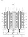
- the self-propelled working robot 100 can be used to perform tasks such as harvesting of agricultural products T in the field 10 illustrated in FIG. 1, for example.
- the field 10 may also be referred to as, for example, a vinyl greenhouse or a plant factory.
- a plurality of cultivation sections 11, a plurality of hot water pipes 12, a plurality of trace lines 13, etc. are provided in the field 10.
- Each of the cultivation units 11 has a plurality of cultivation equipment 11a.
- the cultivation equipment 11a is equipment for cultivating agricultural crops T to be harvested by the self-propelled working robot 100.
- the cultivation equipment 11a is supported within the cultivation section 11 by a support member 11b such as a pillar.
- a plurality of cultivation facilities 11a are arranged on a straight line along the longitudinal direction of the cultivation section 11.
- One cultivation section 11 extends in one direction over a predetermined distance, for example, about ten meters to several tens of meters.
- a plurality of cultivation units 11 are arranged parallel to each other. Further, the plurality of cultivation units 11 are arranged with intervals from each other. In this case, the intervals between the plurality of cultivation units 11 are equal intervals. Note that the intervals between the plurality of cultivation units 11 may be unequal intervals.
- the hot water pipe 12 is provided between two adjacent cultivation sections 11.
- the hot water pipes 12 are each formed by bending a long tubular material into a so-called U-shape, and each extends along the cultivation section 11 .
- Hot water can flow into the hot water pipe 12 from a hot water supply facility (not shown). By flowing hot water through the hot water pipe 12, the temperature within the field 10, particularly the temperature of the area surrounding the cultivation section 11, can be warmed to an appropriate temperature.
- the hot water pipe 12 is provided within the field 10 as an example of a predetermined target.
- the trace line 13 is installed, for example, by pasting, printing, or drawing on the floor of the field 10, and connects the plurality of hot water pipes 12.
- the area within the field 10 where the hot water pipe 12 is provided is defined as a work area R1.
- an area other than the working area R1 in the field 10 and an area that connects a plurality of working areas R1, in this case, an area where the trace line 13 is provided is defined as a non-working area R2. ing.
- the non-working area R2 is included in the path along which the self-propelled working robot 100 travels when not working.
- the work area R1 is basically an area provided on the assumption that work will be performed by the self-propelled work robot 100, and is an area that is provided, for example, by the manager of the field 10 or the user of the self-propelled work robot 100. This is an area created on the assumption that there are no such persons. That is, the work area R1 can basically be defined as a non-coexistence area that is provided on the assumption that the self-propelled working robot 100 and humans will not coexist.
- the non-work area R2 is an area provided on the assumption that the self-propelled working robot 100 will not perform any work, and is an area where, for example, the administrator of the field 10 or the user of the self-propelled working robot 100 This is an area that has been created assuming that there will be people like this. That is, the non-work area R2 can basically be defined as a coexistence area that is provided assuming that the self-propelled working robot 100 and a person coexist.
- a plurality of markers 14 and 15 are provided within the field 10.
- the markers 14 and 15 are located at the boundary between the work area R1 and the non-work area R2, or at the branch point of the trace line 13.
- the marker 14 is provided in the vicinity of the boundary point between the work area R1 and the non-work area R2, at a position within the non-work area R2 just before entering the work area R1.
- the marker 15 is provided at a branch point where the trace line 13, which is provided in a straight line across the plurality of work areas R1, branches to each work area R1.
- the markers 14 and 15 are installed, for example, by pasting, printing, or drawing on the floor of the field 10, and can be photographed by the camera 104 included in the self-propelled working robot 100.
- the markers 14 and 15 can also be configured using an information transmission medium that can transmit information in a non-contact manner using, for example, magnetism, radio waves, images, sound waves, or other methods.
- the markers 14 and 15 can be configured by, for example, RFID, a two-dimensional code, a magnetic marker, or the like.
- the self-propelled working robot 100 includes a robot arm 102 on the top of a robot main body 101 that constitutes a base portion thereof.
- Robot arm 102 is an example of a motion unit.
- the robot arm 102 has a configuration in which a plurality of movable arms are combined, a so-called multi-axis configuration. Therefore, as the robot arm 102, a so-called six-axis robot arm, a four-axis robot arm, or the like can be applied.
- the robot arm 102 is equipped with a harvesting tool 103 and a camera 104 at its tip.
- Harvesting tool 103 is provided as an example of a working unit that performs a predetermined operation, in this case, harvesting work of agricultural products T.
- the robot arm 102 is provided with such a harvesting tool 103 for harvesting agricultural products, and is configured as an operating unit capable of performing harvesting work, which is an example of agricultural work.
- the working unit that can be provided on the robot arm 102 is not limited to the harvesting tool 103, and may be, for example, a tool that performs agricultural work other than harvesting work, or a tool that performs work other than agricultural work.
- the camera 104 is an example of a photographing unit, and is configured to be able to photograph, for example, the trace line 13, markers 14, 15, etc. provided in the field 10.
- the self-propelled work robot 100 can autonomously run while determining its current position based on the trace line 13 photographed by the camera 104, markers 14, 15, etc. .
- the robot arm 102 is configured to be operable in a plurality of operation modes.
- the robot arm 102 is configured to be switchable between at least a motion permissible mode in which motion is permitted and a motion restriction mode in which motion is restricted.
- the operation permission mode is an operation mode in which the robot arm 102 is allowed to perform a harvesting operation of the crops T using the harvesting tool 103 and perform a photographing operation using the camera 104 while moving a plurality of movable arms.
- the operation restriction mode is an operation mode in which the robot arm 102 is restricted from harvesting the crops T with the harvesting tool 103 or photographing with the camera 104 while moving the plurality of movable arms.
- the restriction by the operation restriction mode is intended to restrict or stop the operation of the robot arm 102.
- the restriction by the operation restriction mode may be set to allow some movement of the robot arm 102.
- the self-propelled working robot 100 includes a traveling section 105 at the bottom of the robot main body section 101.
- the traveling section 105 includes a pair of driving wheels 106 and a plurality of driven wheels 107.
- Drive wheel 106 is an example of a wheel. Although detailed illustration is omitted, the drive wheels 106 are configured to be rotated by a drive source such as a motor via a reduction gear, for example.
- the traveling unit 105 mainly rotates the drive wheels 106 to cause the robot main body 101 and the entire self-propelled working robot 100 to travel.
- the driven wheels 107 rotate as the robot main body 101 moves by the driving wheels 106, and support and stabilize the movement of the robot main body 101 and, by extension, the movement of the entire self-propelled working robot 100.
- the robot main body 101 has an elongated generally rectangular shape as a whole, and the traveling section 105 moves the robot main body 101 and the entire self-propelled working robot 100 along the longitudinal direction of the robot main body 101. It is designed to run. That is, in this case, the traveling direction of the robot body 101 and the entire self-propelled working robot 100 is along the longitudinal direction of the robot body 101.
- the robot body section 101 of the self-propelled working robot 100 runs on the hot water pipe 12 by means of a running section 105 within the work area R1. Furthermore, the self-propelled working robot 100 moves within the working area R1 with the longitudinal direction of the robot body 101 along the extending direction of the hot water pipe 12. Therefore, in the field 10 , the hot water pipe 12 is in a state of being extended along the direction in which the robot main body 101 moves by the running section 105 .
- the self-propelled working robot 100 is equipped with a disinfection unit 108.
- the disinfection unit 108 is an example of a disinfection section, and is configured to be able to spray disinfectant from a nozzle (not shown) in a disinfection box with an open top surface.
- the disinfection unit 108 is configured to be able to disinfect the harvesting tool 103 by spraying disinfectant while the robot arm 102 moves the harvesting tool 103 at the tip into the disinfection box of the disinfection unit 108. .
- the self-propelled working robot 100 is equipped with a plurality of obstacle detection sensors 109, in this case two obstacle detection sensors 109.
- the obstacle detection sensors 109 are distributed and arranged at the front and rear parts of the robot main body 101 in the direction of movement.
- the obstacle detection sensor 109 is provided as an example of an obstacle detection unit for detecting obstacles existing around the robot main body 101.
- the obstacle detection sensor 109 includes, for example, a laser sensor or an ultrasonic sensor that detects obstacles existing in the surroundings. Examples of obstacles detected by the obstacle detection sensor 109 include the cultivation equipment 11a, the support member 11b, people, and various types of equipment existing in the field 10. Note that it is preferable that the obstacle detection sensor 109 is configured by a sensor that has acquired a predetermined safety certification.
- the self-propelled working robot 100 is equipped with a plurality of hot water pipe detection sensors 110, in this case two hot water pipe detection sensors 110.
- the hot water pipe detection sensors 110 are also disposed separately at the front and rear parts of the robot main body 101 in the direction of movement.
- the hot water pipe detection sensor 110 is provided as an example of a target detection section, and in this case is configured to be able to detect the hot water pipe 12, which is an example of a target provided in the field 10. A detailed explanation of the configuration and functions of the hot water pipe detection sensor 110 will be given later. Note that it is desirable that the hot water pipe detection sensor 110 be constructed of a sensor that has acquired predetermined safety certification.
- the self-propelled work robot 100 includes a control device 120.
- the control device 120 is mainly composed of, for example, a microcomputer, and controls the overall operation of the self-propelled working robot 100 based on a control program, setting data, and the like.
- one of the two obstacle detection sensors 109 is located at one end in the lateral direction of the robot body 101 at the front of the robot body 101. It is located. Further, the other obstacle detection sensor 109 of the two obstacle detection sensors 109 is arranged at the other end in the lateral direction of the robot body 101 at the rear of the robot body 101 .
- the drive wheel 106 included in the traveling section 105 has a configuration in which a large wheel section 106a and a small wheel section 106b are coaxially combined.
- the large wheel portion 106a is a large diameter wheel that constitutes the main body portion of the drive wheel 106.
- the small wheel portion 106b is a wheel having a smaller diameter than the large wheel portion 106a.
- the rotation axis of the large ring part 106a and the small ring part 106b is common, so that the large ring part 106a and the small ring part 106b rotate integrally.
- the self-propelled working robot 100 When the self-propelled working robot 100 travels in an area other than the work area R1 in the field 10, it travels with the large wheel portion 106a in contact with the floor surface of the field 10. At this time, the small ring portion 106b is not in contact with the floor surface of the field 10 and is spaced apart. Therefore, when the self-propelled working robot 100 travels in an area other than the work area R1 in the field 10, the self-propelled working robot 100 travels mainly by rotating the large wheel portion 106a.
- the self-propelled work robot 100 travels within the work area R1 in the field 10, it travels on the hot water pipe 12 as described above. At this time, as illustrated in FIG. 4, the self-propelled working robot 100 travels with the small wheel portion 106b in contact with the upper surface of the hot water pipe 12. Further, at this time, the large flower portion 106a is not in contact with the floor surface of the field 10 and is spaced apart. Therefore, when the self-propelled working robot 100 travels within the work area R1 in the field 10, the self-propelled working robot 100 travels mainly by rotation of the small wheel portion 106b.
- the hot water pipe detection sensor 110 includes a non-contact switch 111 and a shielding plate 112.
- the non-contact switch 111 is configured to switch between an on state and an off state in response to, for example, an optical or magnetic state change.
- the shielding plate 112 is provided on the side of the non-contact switch 111 so as to be rotatable in the vertical direction.
- the shielding plate 112 is in a non-detection position where the non-contact switch 111 is not covered and exposed as illustrated in FIG. 6, and in a state where the non-contact switch 111 is covered as illustrated in FIG. It is possible to rotate between the detection position and the detection position.
- the shielding plate 112 is urged to rotate from the detection position side illustrated in FIG. 7 to the non-detection position side illustrated in FIG. There is. Further, a support wheel 114 is rotatably provided at the lower end of the shielding plate 112.
- the shielding plate 112 receives the urging force from the urging member 113 and rotates to the non-detection position. As a result, the non-contact switch 111 enters a non-detection state in which the hot water pipe 12 is not detected. on the other hand.
- the shielding plate 112 is pushed upward by the hot water pipe 12 via the support wheels 114. It rotates to the detection position while resisting the urging force of the urging member 113. As a result, the non-contact switch 111 enters a detection state in which the hot water pipe 12 is detected.
- the hot water pipe detection sensor 110 is configured to be able to detect the hot water pipe 12, which is an example of a target, based on the non-contact switch 111 switching to a detection state or a non-detection state.
- control device 120 executes the control program to control the operation control section 121, travel control section 122, safety monitoring section 123, operation mode switching section 124, detection area switching section 125, and mode switching section.
- the section 126 is virtually realized by software. Note that these processing units may be configured by hardware, or may be configured by a combination of software and hardware.
- the motion control unit 121 is configured to be able to control the overall motion of the self-propelled working robot 100. Further, the motion control unit 121 controls the overall motion of the robot arm 102 while recognizing the posture, speed, position, etc. of each part of the robot arm 102. Further, the operation control unit 121 controls the overall harvesting operation by the harvesting tool 103. Further, the operation control unit 121 controls the overall photographing operation by the camera 104.
- the operation control unit 121 analyzes the image taken by the camera 104, recognizes the position and posture of the agricultural product T, which is the work target, and specifies the cutting point. Then, the operation control unit 121 operates the robot arm 102 so that the harvesting tool 103 reaches the specified cutting point. Then, the operation control unit 121 operates the harvesting tool 103 at the identified cutting point. As a result, the operation control unit 121 is configured to be able to harvest the crops T, which are work objects, using the robot arm 102 equipped with the harvesting tool 103 and the camera 104 .
- the self-propelled working robot 100 may be configured to include a collection box for collecting agricultural products T harvested by the robot arm 102.
- the travel control unit 122 is configured to be able to control the travel of the robot main body 101 and the entire self-propelled working robot 100 by the travel unit 105.
- the travel control unit 122 is connected to, for example, an encoder, an angle sensor, a rotation speed sensor that measures the rotation speed of the motor, and the like. Based on the control by the travel control unit 122, the travel unit 105 rotates the drive wheels 106 to move the robot body 101 and the entire self-propelled working robot 100, depending on the detection status of the hot water pipe 12 by the hot water pipe detection sensor 110. It is configured so that the speed can be switched.
- the traveling section 105 is configured to be able to switch the moving speed of the robot main body section 101 and of the self-propelled working robot 100 as a whole.
- the self-propelled working robot 100 when the self-propelled working robot 100 travels in an area other than the work area R1 in the field 10, the self-propelled working robot 100 mainly runs by rotating the large wheel portion 106a.
- the self-propelled work robot 100 travels within the work area R1 in the field 10, the self-propelled work robot 100 travels mainly by rotation of the small wheel portion 106b. Therefore, if the drive wheels 106 are rotated at the same rotational speed regardless of the area in which the self-propelled work robot 100 travels, the movement speed of the self-propelled work robot 100 when traveling in an area other than work area R1 will be The moving speed of the self-propelled working robot 100 when traveling within the work area R1 becomes relatively slow.
- the travel control unit 122 increases the rotational speed of the drive wheels 106. It is better to do this.
- the travel control unit 122 is configured to be able to switch the travel unit 105 to at least a harvesting mode, an aisle traveling mode, and a transition mode.
- the harvest time mode is a traveling mode that assumes that the self-propelled working robot 100 is run within the work area R1, and it is possible to run the self-propelled working robot 100 at a predetermined high speed. Note that the predetermined high speed can be changed and set as appropriate within a speed range that ensures sufficient safety.
- the aisle traveling mode is a traveling mode in which the self-propelled working robot 100 is assumed to travel in an area other than the work area R1, and the self-propelled working robot 100 is run at a predetermined low speed or stopped. It is possible to do so.
- the predetermined low speed can be appropriately changed and set within a speed range that ensures sufficient safety and is lower than the above-mentioned predetermined high speed.
- the transition mode is assumed to be when the self-propelled work robot 100 is moved from outside the work area R1 to inside the work area R1, and when the self-propelled work robot 100 is moved from inside the work area R1 to outside the work area R1.
- This is a running mode in which the self-propelled working robot 100 can run at a predetermined low speed.
- the predetermined low speed in the transition mode is assumed to be a speed that is even slower than the predetermined low speed in the aisle traveling mode.
- the predetermined low speed in the transition mode may be a speed equivalent to the predetermined low speed in the aisle traveling mode, or a speed that is slightly faster than the predetermined low speed in the aisle traveling mode. Good too.
- the safety monitoring unit 123 is configured to be able to monitor at least whether the behavior of the robot arm 102 and the traveling unit 105 is in a safe state. Furthermore, the safety monitoring unit 123 is configured to be able to monitor whether the behavior of the self-propelled working robot 100 as a whole is in a safe state.
- the safety monitoring unit 123 functions as a control unit that controls the behavior of the robot arm 102, the traveling unit 105, and the self-propelled working robot 100 as a whole. Note that an appropriate state can be set as the safe state, assuming at least that the self-propelled working robot 100 will not harm people.
- the safety monitoring section 123 is preferably configured by a control section that has acquired a predetermined safety certification.
- the operation mode switching unit 124 is configured to be able to switch the operation mode of the robot arm 102 according to the detection status of the hot water pipe 12 by the hot water pipe detection sensor 110.
- the operation mode switching unit 124 is configured to switch the operation mode of the robot arm 102 from the operation restriction mode to the operation permission mode when the hot water pipe detection sensor 110 detects the hot water pipe 12. Further, the operation mode switching unit 124 is configured to switch the operation mode of the robot arm 102 from the operation permission mode to the operation restriction mode when the hot water pipe detection sensor 110 does not detect the hot water pipe 12.
- the detection area switching unit 125 is configured to be able to switch the detection area of an obstacle by the obstacle detection sensor 109. In this case, the detection area switching unit 125 is configured to switch the detection area of the obstacle depending on the detection status of the hot water pipe 12 by the hot water pipe detection sensor 110.
- the detection area switching unit 125 changes the detection area of the obstacle by the obstacle detection sensor 109, as illustrated in FIG. is switched to the out-of-lane pattern Pa.
- the out-of-lane pattern Pa can also be defined as a non-work pattern assuming that the robot arm 102 does not perform any work.
- a plurality of detection areas are formed, in this case, a first deceleration area Pa1, a second deceleration area Pa2, and a stop area Pa3.
- the first deceleration area Pa1, the second deceleration area Pa2, and the stop area Pa3 are all rectangular frame-shaped detection areas centered on the self-propelled working robot 100. Further, the first deceleration area Pa1 is provided outside the second deceleration area Pa2, the second deceleration area Pa2 is provided outside the stop area Pa3, and the stop area Pa3 is provided outside the self-propelled work robot 100. It is provided.
- the out-of-lane pattern Pa is a detection area pattern that covers the entire periphery of the self-propelled working robot 100 including the front, rear, left side, and right side.
- the travel control unit 122 changes the movement speed of the self-propelled work robot 100 to the first speed for non-work. slow down.
- the first speed for non-work can be changed and set as appropriate in a speed range slower than the speed for non-work that is set as the movement speed of the self-propelled work robot 100 in areas other than the work area R1.
- the non-work speed can be changed and set as appropriate within a speed range that ensures sufficient safety when the self-propelled work robot 100 travels in an area other than the work area R1. .
- the traveling control unit 122 changes the movement speed of the self-propelled working robot 100 to the second deceleration area Pa2. slow down to speed.
- the second speed for non-working times can be changed and set as appropriate in a speed range slower than the first speed for non-working times.
- the traveling control unit 122 stops the traveling of the self-propelled working robot 100.
- the detection area switching unit 125 changes the detection area of the obstacle by the obstacle detection sensor 109 into an in-lane pattern, as illustrated in FIG. Switch to Pb.
- the in-lane pattern Pb can also be defined as a working pattern assuming that the robot arm 102 performs the work.
- a plurality of detection areas in this case, a first deceleration area Pb1, a second deceleration area Pb2, and a stop area Pb3 are formed.
- the first deceleration area Pb1, the second deceleration area Pb2, and the stop area Pb3 are all long rectangular detection areas along the width direction of the self-propelled work robot 100 before and after the self-propelled work robot 100. It becomes. Further, the first deceleration area Pb1 is provided outside the second deceleration area Pb2, the second deceleration area Pb2 is provided outside the stop area Pb3, and the stop area Pb3 is provided outside the self-propelled work robot 100. It is provided.
- the intra-lane pattern Pb is a detection area pattern that includes the front and rear sides of the self-propelled work robot 100 and excludes the left side and right side, that is, the self-propelled work robot 100 in the work area R1.
- the detection area pattern covers the area along the traveling direction of the vehicle.
- the travel control unit 122 reduces the movement speed of the self-propelled work robot 100 to the first speed for work. let The first speed for work can be appropriately changed and set within a speed range slower than the speed for work that is set as the movement speed of the self-propelled work robot 100 within the work area R1. Note that the speed for work can be changed and set as appropriate within a speed range that ensures sufficient safety when the self-propelled work robot 100 travels within the work area R1.
- the travel control unit 122 changes the movement speed of the self-propelled work robot 100 to the second speed for work. decelerate to.
- the second speed for work can be changed and set as appropriate in a speed range slower than the first speed for work.
- the travel control unit 122 stops the self-propelled working robot 100 from traveling.
- the working speed is assumed to be slower than the non-working speed
- the first working speed is assumed to be slower than the non-working first speed
- the second speed for use is assumed to be slower than the second speed for non-work.
- the form switching unit 126 is configured to be able to switch the form of the robot arm 102 according to the detection status of the hot water pipe 12 by the hot water pipe detection sensor 110.
- the robot arm 102 selects the detection mode that is set as the mode that should be taken or the recommended mode when the hot water pipe detection sensor 110 detects the hot water pipe 12, and It is configured to be switchable to a non-detection mode that is set as a mode to be taken when the pipe 12 is not detected or a recommended mode.
- the non-detection state may be such that the robot arm 102 moves the harvesting tool 103 at the tip into the disinfection unit 108, or the robot arm 102 moves the camera 104 at the tip to a predetermined object to be photographed.
- the image may be moved to a position where it can be photographed, or it may be formed in any other suitable form. That is, as the non-detection mode, various modes can be applied as long as the robot arm 102 does not come into direct contact with people or the like existing around the self-propelled working robot 100.
- the detection state may be, for example, a state in which the robot arm 102 is immediately ready for operation, in other words, a state in which it is in a standby state, or a state in which the robot arm 102 is in a state in which the harvesting tool 103 at the tip is disinfected. It may be in a form in which it is moved outside the unit 108, or it may be in an appropriate form different from the non-detection form described above.
- the form switching unit 126 changes the form of the robot arm 102 from the detection state to the detection state. It is configured to switch to a non-detection mode.
- the form switching unit 126 maintains the robot arm 102 in the detection state. In this state, the robot main body 101 and the entire self-propelled working robot 100 are caused to travel by the traveling section 105 until the hot water pipe detection sensor 110 detects the hot water pipe 12. Then, the form switching unit 126 operates on the condition that the hot water pipe detection sensor 110 is in a state to detect the hot water pipe 12, in other words, on the condition that the self-propelled working robot 100 has moved into the work area R1. In addition, the robot arm 102 is configured to switch its configuration from a detection mode to a non-detection mode.
- the robot arm 102 is switched from the detection mode to the non-detection mode while the self-propelled working robot 100 is present in an area other than the work area R1, the robot arm 102 is may come into contact with people or obstacles.
- the hot water pipe detection sensor 110 does not detect the hot water pipe 12 and the robot arm 102 is switched to the detection mode, the self-propelled working robot 100 is moved into the work area R1 in that state. It is preferable to switch the configuration of the robot arm 102 from the detection mode to the non-detection mode after the robot arm 102 is moved. In other words, the transformation of the robot arm 102 from the detection mode to the non-detection mode is preferably performed within the work area R1. This makes it possible to avoid the robot arm 102 from coming into contact with people or obstacles during the shape transformation.
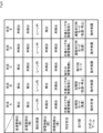
- FIG. 9 shows an example of the correspondence between the detection states of the hot water pipe detection sensor 110 and the obstacle detection sensor 109 and the modes of each part.
- the hot water pipe detection sensor 110 on the front side is in the detection state
- the hot water pipe detection sensor 110 on the rear side is in the detection state.
- the control device 120 switches the obstacle detection area by the obstacle detection sensor 109 to the in-lane pattern Pb.
- the front obstacle detection sensor 109 is in an undetected state, and the rear obstacle detection sensor 109 is not detected. state.
- control device 120 determines that the self-propelled work robot 100 exists in the work area R1 and that there are obstacles around the self-propelled work robot 100, in this case, in front and behind the self-propelled work robot 100. It is determined that there is no such situation.
- control device 120 switches the traveling mode of the traveling section 105 to the harvesting mode to enable traveling at a predetermined high speed. Further, the control device 120 switches the operation mode of the robot arm 102 to the operation permission mode to enable the robot arm 102 to operate. Thereby, the self-propelled working robot 100 can perform harvesting work using the robot arm 102 within the working area R1.
- situation pattern B when the obstacle detection area by the obstacle detection sensor 109 is switched to the in-lane pattern Pb, the front obstacle detection sensor 109 is in the detection state, and the rear obstacle detection area is switched to the in-lane pattern Pb.
- the object detection sensor 109 is in an undetected state.
- control device 120 detects a state in which the self-propelled work robot 100 exists in the work area R1 and there is an obstacle around the self-propelled work robot 100, in this case, in front of the self-propelled work robot 100. It is determined that
- control device 120 switches the traveling mode of the traveling section 105 to the harvesting mode to enable traveling at a predetermined high speed.
- the control device 120 switches the travel mode of the travel unit 105 to the harvesting mode, but does not control the self-propelled work robot 100.
- the moving speed is adjusted to a predetermined low speed, and depending on the situation, the self-propelled working robot 100 is stopped from traveling.
- control device 120 switches the operation mode of the robot arm 102 to the operation restriction mode to limit the operation of the robot arm 102. Thereby, it is possible to avoid the robot arm 102 from operating and coming into contact with an obstacle. At this time, the control device 120 can, for example, slow down the operation speed of the robot arm 102 or stop the operation of the robot arm 102. Note that the control device 120 is configured to control, for example, slowing down the operating speed of the robot arm 102 or temporarily stopping the operation of the robot arm 102, while setting the operation mode of the robot arm 102 to the operation permissible mode. It's okay.
- the hot water pipe detection sensor 110 on the front side is in the detection state
- the hot water pipe detection sensor 110 on the rear side is in the non-detection state.
- one of the two hot water pipe detection sensors 110 at the front and rear of the self-propelled working robot 100 is in an undetected state. Therefore, if the self-propelled work robot 100 is in the middle of moving from outside the work area R1 to inside the work area R1, or in the middle of moving from inside the work area R1 to outside the work area R1, can be judged.
- the control device 120 switches the obstacle detection area by the obstacle detection sensor 109 to the in-lane pattern Pb. That is, the control device 120 prevents obstacles from occurring as long as the entire self-propelled work robot 100 does not move outside the work area R1, in other words, as long as a part of the self-propelled work robot 100 remains within the work area R1.
- the vehicle is configured to switch the obstacle detection area by the object detection sensor 109 to the in-lane pattern Pb.
- the control device 120 may switch the detection area of the obstacle by the obstacle detection sensor 109 to the out-of-lane pattern Pa when at least a part of the obstacle moves outside the work area R1.
- the front obstacle detection sensor 109 is in an undetected state, and the rear obstacle detection sensor 109 is not detected. state.
- control device 120 can control the state in which the self-propelled work robot 100 is moving from outside the work area R1 to inside the work area R1, or while the self-propelled work robot 100 is moving from inside the work area R1 to outside the work area R1. It is determined that the state is Further, the control device 120 determines that there are no obstacles around the self-propelled working robot 100, in this case, in front and behind the self-propelled working robot 100.
- control device 120 switches the traveling mode of the traveling section 105 to the transition mode to enable traveling at a predetermined low speed. Further, the control device 120 switches the operation mode of the robot arm 102 to the operation restriction mode to limit the operation of the robot arm 102. As a result, the self-propelled work robot 100 cannot move from outside the work area R1 to inside the work area R1, or from inside the work area R1 to outside the work area R1, while the movement of the robot arm 102 is restricted. It can be carried out. Note that at this time, the control device 120 may maintain, for example, a state in which the operation of the robot arm 102 is stopped.
- the self-propelled working robot 100 It is estimated that the object is in the middle of moving from outside the work area R1 into the inside of the work area R1, or in the middle of moving from inside the work area R1 to outside the work area R1. Therefore, it is preferable that the control device 120 performs the same control as in situation pattern C described above in this case as well.
- the hot water pipe detection sensor 110 on the front side is in an undetected state
- the hot water pipe detection sensor 110 on the rear side is in an undetected state.
- both the front and rear hot water pipe detection sensors 110 of the self-propelled working robot 100 are in a non-detection state. Therefore, it can be determined that the self-propelled working robot 100 is present in an area other than the work area R1. Therefore, the control device 120 switches the obstacle detection area by the obstacle detection sensor 109 to the out-of-lane pattern Pa.
- the front obstacle detection sensor 109 is in an undetected state, and the rear obstacle detection sensor 109 is not detected. state.
- control device 120 controls the self-propelled working robot 100 when the self-propelled working robot 100 exists in an area other than the work area R1, for example, in a passage in the field 10, and the area around the self-propelled working robot 100, in this case, the self-propelled working robot 100 It is determined that there are no obstacles in front or behind the work robot 100 in the direction of movement.
- control device 120 switches the traveling mode of the traveling section 105 to the aisle traveling mode to enable traveling at a predetermined low speed. Further, the control device 120 switches the operation mode of the robot arm 102 to the operation restriction mode to limit the operation of the robot arm 102. Thereby, the self-propelled work robot 100 can travel in areas other than the work area R1 while the movement of the robot arm 102 is restricted. Note that at this time, the control device 120 may maintain, for example, a state in which the operation of the robot arm 102 is stopped.
- the obstacle detection area by the obstacle detection sensor 109 is switched to the out-of-lane pattern Pa, the front obstacle detection sensor 109 is in the detection state, and the obstacle detection area on the rear side is in the detection state.
- the object detection sensor 109 is in an undetected state.
- the control device 120 controls the self-propelled working robot 100, It is determined that there is an obstacle in front of the robot 100 in the direction of movement.
- control device 120 switches the traveling mode of the traveling section 105 to the aisle traveling mode to enable traveling at a predetermined low speed.
- the control device 120 may switch the traveling mode of the traveling unit 105 to the aisle traveling mode, but may The movement of the type work robot 100 is stopped.
- control device 120 switches the operation mode of the robot arm 102 to the operation restriction mode to limit the operation of the robot arm 102. Thereby, it is possible to avoid the robot arm 102 from operating and coming into contact with an obstacle. At this time, the control device 120 can maintain, for example, a state in which the operation of the robot arm 102 is stopped.
- the robot arm 102 is configured to be operable in a plurality of operation modes
- the robot main body 101 is provided with the robot arm 102
- the robot main body 101 is configured to operate in a plurality of operation modes.
- a switching unit 124 is provided.
- the operation mode of the robot arm 102 can be switched as appropriate depending on the detection status of the hot water pipe 12 by the hot water pipe detection sensor 110.
- the robot arm 102 can be The operation mode of the device can be switched between the operation permission mode and the operation restriction mode with high accuracy.
- the hot water pipe 12 which is an example of a target, extends along the traveling direction of the robot main body 101 and the entire self-propelled working robot 100 by the traveling section 105.
- the hot water pipe 12 in the area where the hot water pipe 12 extends, the hot water pipe 12 can be continuously detected as the self-propelled working robot 100 advances, and a situation where the hot water pipe 12 cannot be detected can be prevented. This can be avoided.
- the operation mode of the robot arm 102 can be switched to the operation permissible mode within the area. It is possible to continue to maintain the state that has been maintained.
- the robot main body 101 and by extension the entire self-propelled working robot 100, travels over the target hot water pipe 12 by the traveling section 105.
- the target hot water pipe 12 exists directly below the traveling self-propelled working robot 100, the hot water pipe 12 can be detected even more easily.
- the detection area switching unit 125 switches the detection area by the obstacle detection sensor 109 according to the detection status of the hot water pipe 12 by the hot water pipe detection sensor 110.
- the hot water pipe 12 In a state where the hot water pipe 12 is detected by the hot water pipe detection sensor 110, there is a high possibility that the self-propelled working robot 100 exists within the work area R1. Therefore, by switching the obstacle detection area by the obstacle detection sensor 109 to an area suitable for work, in this case, the in-lane pattern Pb, for example, the cultivation equipment 11a or the support member 11b may be detected as an obstacle. can be avoided.
- the hot water pipe 12 is not detected by the hot water pipe detection sensor 110, there is a high possibility that the self-propelled working robot 100 exists in an area other than the work area R1. Therefore, by switching the obstacle detection area by the obstacle detection sensor 109 to an area suitable for non-work, in this case to the outside lane pattern Pa, for example, a person existing in an area other than the work area R1 can be detected as an obstacle. This can be detected and safety can be improved.
- the robot arm 102 can be switched to at least a motion permissible mode in which motion is permitted and a motion restriction mode in which motion is restricted. Then, when the hot water pipe detection sensor 110 detects the hot water pipe 12, the operation mode switching unit 124 switches the operation mode of the robot arm 102 from the operation restriction mode to the operation permission mode.
- the hot water pipe detection sensors 110 are provided at the front and rear parts of the robot main body 101 in the direction of movement.
- the entire self-propelled working robot 100 is present on the hot water pipe 12, that is, within the work area R1. This can be determined with high accuracy.
- the self-propelled working robot 100 is entirely or partially outside the work area R1. It can be determined with high accuracy.
- the robot arm 102 operates outside the work area R1. It is possible to avoid putting it away, and it is possible to further improve safety.
- the self-propelled working robot 100 includes a form switching unit 126 that switches the form of the robot arm 102 according to the detection status of the hot water pipe 12 by the hot water pipe detection sensor 110. Then, the robot arm 102 selects a detection mode that is set as a mode to be taken or a recommended mode when the hot water pipe detection sensor 110 detects the hot water pipe 12, and It is possible to switch to a non-detection mode that is set as a mode to be taken when 12 is not detected or a recommended mode. Then, when the hot water pipe detection sensor 110 does not detect the hot water pipe 12 and the robot arm 102 is switched to the detection state, the form switching unit 126 changes the form of the robot arm 102 to the detection state. to switch to non-detection mode.
- the robot arm 102 when the robot arm 102 is switched to the detection mode when the hot water pipe detection sensor 110 is not detecting the hot water pipe 12, The robot main body 101 is caused to travel by the traveling unit 105 until the hot water pipe detection sensor 110 detects the hot water pipe 12, and then the form of the robot arm 102 is switched from the detection state to the non-detection state.
- the hot water pipe detection sensor 110 does not detect the hot water pipe 12 and the robot arm 102 is switched to the detection mode, the hot water pipe detection sensor 110 will not detect the hot water pipe 12 until the hot water pipe detection sensor 110 detects the hot water pipe 12. It is preferable to switch the form of the robot arm 102 after the robot main body section 101 is driven by the traveling section 105, that is, after the self-propelled working robot 100 is moved into the work area R1. Thereby, the robot arm 102 can be prevented from coming into contact with a person during shape deformation, and safety can be improved.
- the self-propelled working robot 100 includes a harvesting tool 103 provided on the robot arm 102 and a disinfection unit 108 that disinfects the harvesting tool 103. Therefore, as the non-detection state, for example, a state in which the harvesting tool 103 is moved into the disinfection unit 108 may be set.
- the harvesting tool 103 is moved into the disinfection unit 108, it is easier to avoid the harvesting tool 103 coming into contact with people, and safety can be further improved. Further, the robot arm 102 is set in the non-detection state mainly when the robot arm 102 is not performing any work. Therefore, by adopting a configuration in which the harvesting tool 103 is moved into the disinfection unit 108 as the non-detection mode, the harvesting tool 103 can be disinfected by the disinfection unit 108 during non-operation, and the disinfection work can be carried out efficiently. It can be carried out.
- the self-propelled working robot 100 includes a camera 104 provided on the robot arm 102. Therefore, as the non-detection mode, for example, a mode may be set in which the camera 104 moves to a position where a predetermined photographic object can be photographed.
- the robot arm 102 is in the non-detection state mainly when the robot arm 102 is not performing any work, and when the robot arm 102 is not working, the self-propelled working robot 100 is in the non-detection state. It is assumed that the vehicle will be driven in the following areas. Therefore, by adopting a configuration in which the camera 104 moves to a position where it can photograph a predetermined object to be photographed, such as the trace line 13 or the markers 14 and 15, as the non-detection mode, the self-propelled It is possible to easily photograph an object to be photographed when the working robot 100 is traveling, and it is possible to easily support the traveling of the self-propelled working robot 100 when not working.
- a predetermined object to be photographed such as the trace line 13 or the markers 14 and 15
- the traveling unit 105 is a driving wheel that moves the robot main body 101 and the entire self-propelled working robot 100 according to the detection status of the hot water pipe 12 by the hot water pipe detection sensor 110.
- the rotation speed of 106 can be switched.
- the driving wheels are driven at the same rotational speed in the case where the large wheel portion 106a is mainly used to travel in an area other than the work area R1, and when the small wheel portion 106b is mainly used to travel over the hot water pipe 12 in the work area R1.
- the movement speed of the self-propelled work robot 100 when traveling in an area other than the work area R1 becomes relatively faster, and the movement speed of the self-propelled work robot 100 when traveling within the work area R1 becomes relatively faster. Movement speed becomes relatively slow.
- the running speed of the self-propelled working robot 100 becomes excessively slow. It is possible to avoid putting it away, and it is possible to suppress the occurrence of a situation where the work time becomes longer.
- the driving speed of the drive wheels is increased, the distance traveled per unit time becomes longer, so it is conceivable to widen the obstacle detection area.
- the rotation speed of the drive wheel 106 is increased, the rotation speed of the small wheel portion 106b is increased, not the large wheel portion 106a.
- the overall movement speed is not that much faster.
- the self-propelled work robot 100 if the rotation speed of the drive wheels 106 is increased but the detection area of obstacles by the obstacle detection sensor 109 is also widened, for example, the self-propelled work robot 100 may Even though the type work robot 100 is sufficiently far from the end of the work area R1, there is a risk that a wall or the like existing at the end of the work area R1 will be detected as an obstacle by the obstacle detection sensor 109. be.
- the self-propelled work robot 100 is controlled to reduce its movement speed or stopped, even though the self-propelled work robot 100 has not approached the edge of the work area R1. There is a concern that control may be carried out that causes
- the self-propelled working robot 100 is configured to switch the detection area of the obstacle by the obstacle detection sensor 109 to the in-lane pattern Pb when the obstacle exists within the work area R1. Therefore, even if the traveling speed of the self-propelled work robot 100 in the work area R1 is increased, the obstacle detection area by the obstacle detection sensor 109 will not be too wide to be suitable for traveling in the work area R1. Can be set in the area. Therefore, it is possible to avoid controlling the self-propelled working robot 100 from slowing down or stopping it even though there is still a distance to the end of the working area R1.
- the self-propelled working robot 100 includes a safety monitoring unit 123 that monitors whether the behavior of the entire self-propelled working robot 100 including at least the robot arm 102 and the traveling unit 105 is in a safe state.
- the safety monitoring section 123 functions as a control section that controls the behavior of the entire self-propelled working robot 100 including at least the robot arm 102 and the traveling section 105.
- the self-propelled working robot 100 can perform work and travel in a safe state based on control by the control unit.
- safety monitoring unit 123 by configuring the safety monitoring unit 123 with a control unit that has obtained predetermined safety certification, safety can be further ensured. Furthermore, by configuring various sensors such as the hot water pipe detection sensor 110 and the obstacle detection sensor 109 with sensors that have obtained predetermined safety certification, safety can be further ensured. . Further, by configuring other components constituting the self-propelled working robot 100 with components that have obtained predetermined safety certification, safety can be further ensured. Note that various safety certification standards such as those established by the International Organization for Standardization (ISO) can be adopted as the safety certification.
- ISO International Organization for Standardization
- the self-propelled working robot 100 includes a robot arm 102 that can perform agricultural work, it may also be configured to include a robot arm that can perform tasks other than agricultural work.
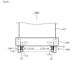
- the self-propelled working robot 100 is configured to include hot water pipe detection sensors 110 on both sides of the robot body 101 in the lateral direction.
- the two hot water pipe detection sensors 110 can detect the inclination of the hot water pipe 12 or the width dimension of the hot water pipe 12 in the horizontal direction.
- the width dimension of the hot water pipe 12 can also be defined as a dimension in a direction orthogonal to the longitudinal direction of the hot water pipe 12.
- the width dimension of the hot water pipe 12 in the horizontal direction may become narrower or wider due to factors such as, for example, the hot water pipe 12 being tilted, aging or damage to the hot water pipe 12, and the like. If a change in the inclination or width of the hot water pipe 12 is detected, the control device 120 may, for example, reduce the traveling speed of the self-propelled work robot 100, stop traveling, or cause an error.
- the error notification may be, for example, displayed on the display of the operation input unit included in the self-propelled working robot 100, lit or blinking a warning lamp, or notified by voice or sound via a speaker or the like. You may.
- the present disclosure is not limited to the plurality of embodiments described above, and can be modified and expanded as appropriate without departing from the gist thereof.
- the self-propelled working robot 100 can be configured by appropriately selecting and combining the plurality of embodiments described above.
- the target is not limited to the hot water pipe 12, but may be another element that can be detected by the self-propelled working robot 100 in the field 10, for example.
- the target may be, for example, a predetermined object provided at the entrance of the work area R1.
- the self-propelled work robot 100 when it detects a predetermined object, it may maintain the detection state, ie, latch it, and when it detects the predetermined object again, it may switch to the non-detection state, ie, the non-latching state.
- the target detection unit may be configured to detect the target not by a non-contact type switch, but may be configured to detect the target using, for example, a contact type switch, a switch using communication or light, or a configuration that detects the target using RFID.
- the target may be detected by recognition of a code or the like by the camera 104. That is, various configurations can be applied as long as the configuration can detect the target using some method.
- the target detection unit may be configured to be able to detect the target while the self-propelled working robot 100 is running, or may be configured to be able to detect the target while the self-propelled working robot 100 is stopped. good.
- the self-propelled working robot 100 may be configured to allow the robot arm 102 to operate at positions other than the position where the target is detected by the target detection unit, or only at the position where the target is detected by the target detection unit. The configuration may be such that the robot arm 102 is allowed to operate.
- the self-propelled working robot 100 may be configured to allow the robot arm 102 to operate on the condition that a sufficiently safe state is ensured by the safety monitoring unit 123, for example.
- the number of target detection units mounted on one self-propelled working robot 100 is not limited to two, and may be one or three or more.
- the placement position of the target detection unit is not limited to the front or rear of the self-propelled working robot 100, but may be, for example, on the left side or right side, or on the top or bottom. However, other parts may be used.
- the number of obstacle detection units mounted on one self-propelled working robot 100 is not limited to two, and may be one or three or more.
- the location of the obstacle detection unit is not limited to the front or rear of the self-propelled working robot 100, but may be placed on the left or right side, or on the top or bottom. It may also be in other parts. Further, the present disclosure can also be applied to self-propelled working robots that perform tasks other than agricultural work.
- control unit and the method described in the present disclosure may be implemented by a dedicated computer provided by configuring a processor and memory programmed to perform one or more functions embodied by a computer program. It may be realized.
- controller and techniques described in this disclosure may be implemented by a dedicated computer provided by configuring the processor with one or more dedicated hardware logic circuits.
- control unit and the method described in the present disclosure may be implemented using a combination of a processor and memory programmed to execute one or more functions and a processor configured with one or more hardware logic circuits. It may be implemented by one or more dedicated computers configured.
- the computer program may also be stored as instructions executed by a computer on a computer-readable non-transitory tangible storage medium.
- the present disclosure further includes the following inventions.
- an operating section (102) configured to be operable in a plurality of operating modes; a robot main body section (101) in which the operating section is provided; a traveling section (105) that causes the robot main body to travel; a target detection unit (110) configured to be able to detect a predetermined target; an operation mode switching unit (124) that switches the operation mode of the operation unit according to the detection status of the target by the target detection unit;
- the operation unit is switchable between an operation permission mode in which operation is permitted and an operation restriction mode in which operation is restricted; 5.
- the operation mode switching section switches the operation mode of the operation section from the operation restriction mode to the operation permission mode when the target detection section detects the target.
- [Claim 6] The self-propelled working robot according to any one of claims 1 to 5, wherein the target detection section is provided at a front portion and a rear portion of the robot main body portion in a traveling direction.
- [Claim 7] comprising a form switching unit (126) that switches the form of the operating unit depending on the detection status of the target by the target detection unit;
- the operating unit includes a detection mode that is set as a configuration that should be taken when the target detection unit is detecting the target, and a configuration that is set as a configuration that should be taken when the target detection unit is not detecting the target.
- the mode switching section changes the mode of the operating section from the detection mode to the non-detection mode when the operating section is switched to the detection mode when the target detection section does not detect the target.
- the self-propelled working robot according to any one of claims 1 to 6, wherein the self-propelled working robot switches to a detection mode.
- the mode switching section is configured to bring the target detection section into a state where the target detection section detects the target when the operation section is switched to the detection mode when the target detection section does not detect the target. 8.
- a working part (103) that is provided in the operating part and performs a predetermined work; a disinfection section (108) for disinfecting the working section; Equipped with 9.
- the non-detection state is a state in which the working part has moved into the disinfection part.
- [Claim 10] comprising an imaging unit (104) provided in the operating unit, 9.
- the traveling section switches the rotational speed of wheels for moving the robot body according to the detection status of the target by the target detection section. .
- a safety monitoring unit (123) that monitors whether the behavior of the operating unit and the traveling unit is in a safe state.
Landscapes
- Engineering & Computer Science (AREA)
- Robotics (AREA)
- Aviation & Aerospace Engineering (AREA)
- Radar, Positioning & Navigation (AREA)
- Remote Sensing (AREA)
- Physics & Mathematics (AREA)
- General Physics & Mathematics (AREA)
- Automation & Control Theory (AREA)
- Mechanical Engineering (AREA)
- Life Sciences & Earth Sciences (AREA)
- Environmental Sciences (AREA)
- Health & Medical Sciences (AREA)
- General Health & Medical Sciences (AREA)
- Orthopedic Medicine & Surgery (AREA)
- Manipulator (AREA)
- Control Of Position, Course, Altitude, Or Attitude Of Moving Bodies (AREA)
Priority Applications (6)
| Application Number | Priority Date | Filing Date | Title |
|---|---|---|---|
| AU2023268200A AU2023268200A1 (en) | 2022-05-11 | 2023-04-11 | Self-propelled work robot |
| CN202380039453.2A CN119212828A (zh) | 2022-05-11 | 2023-04-11 | 自走式作业机器人 |
| EP23803317.9A EP4523516A4 (en) | 2022-05-11 | 2023-04-11 | SELF-PROPELLED WORKING ROBOT |
| CA3252642A CA3252642A1 (en) | 2022-05-11 | 2023-04-11 | SELF-PROPELLED WORK ROBOT |
| JP2024520306A JP7619527B2 (ja) | 2022-05-11 | 2023-04-11 | 自走式作業ロボット |
| US18/929,826 US20250053178A1 (en) | 2022-05-11 | 2024-10-29 | Self-propelled work robot |
Applications Claiming Priority (2)
| Application Number | Priority Date | Filing Date | Title |
|---|---|---|---|
| JP2022078208 | 2022-05-11 | ||
| JP2022-078208 | 2022-05-11 |
Related Child Applications (1)
| Application Number | Title | Priority Date | Filing Date |
|---|---|---|---|
| US18/929,826 Continuation US20250053178A1 (en) | 2022-05-11 | 2024-10-29 | Self-propelled work robot |
Publications (1)
| Publication Number | Publication Date |
|---|---|
| WO2023218835A1 true WO2023218835A1 (ja) | 2023-11-16 |
Family
ID=88730104
Family Applications (1)
| Application Number | Title | Priority Date | Filing Date |
|---|---|---|---|
| PCT/JP2023/014728 Ceased WO2023218835A1 (ja) | 2022-05-11 | 2023-04-11 | 自走式作業ロボット |
Country Status (7)
| Country | Link |
|---|---|
| US (1) | US20250053178A1 (https=) |
| EP (1) | EP4523516A4 (https=) |
| JP (1) | JP7619527B2 (https=) |
| CN (1) | CN119212828A (https=) |
| AU (1) | AU2023268200A1 (https=) |
| CA (1) | CA3252642A1 (https=) |
| WO (1) | WO2023218835A1 (https=) |
Cited By (3)
| Publication number | Priority date | Publication date | Assignee | Title |
|---|---|---|---|---|
| WO2025234269A1 (ja) * | 2024-05-08 | 2025-11-13 | 株式会社デンソー | 収穫ロボット |
| WO2025234271A1 (ja) * | 2024-05-08 | 2025-11-13 | 株式会社デンソー | 農作物収穫システム |
| JP7789148B1 (ja) | 2024-08-30 | 2025-12-19 | 三菱重工業株式会社 | 作業ロボット、作業ロボットの制御方法 |
Citations (5)
| Publication number | Priority date | Publication date | Assignee | Title |
|---|---|---|---|---|
| JPH1110568A (ja) * | 1997-06-26 | 1999-01-19 | Mitsubishi Electric Corp | 無人搬送装置 |
| JP2014176934A (ja) * | 2013-03-15 | 2014-09-25 | Yaskawa Electric Corp | ロボットシステム、及び、ロボットシステムの制御方法 |
| JP2021115662A (ja) * | 2020-01-27 | 2021-08-10 | トヨタ自動車株式会社 | 作業システム |
| JP2021126770A (ja) * | 2020-01-17 | 2021-09-02 | 川崎重工業株式会社 | 安全装置、自走式ロボットシステム、及び制御方法 |
| JP2022047381A (ja) * | 2020-09-11 | 2022-03-24 | 株式会社東芝 | 移動体、制御装置、監視装置、制御方法、及びプログラム |
Family Cites Families (3)
| Publication number | Priority date | Publication date | Assignee | Title |
|---|---|---|---|---|
| GB2580991B (en) * | 2019-07-22 | 2021-05-05 | Kingdom Tech Ltd | Robotic lawn mower control |
| JP7382597B2 (ja) * | 2019-11-28 | 2023-11-17 | 川崎重工業株式会社 | ロボットシステムおよびロボットセル |
| JP7140097B2 (ja) * | 2019-12-25 | 2022-09-21 | 株式会社デンソー | 農作物収穫システム |
-
2023
- 2023-04-11 AU AU2023268200A patent/AU2023268200A1/en active Pending
- 2023-04-11 CA CA3252642A patent/CA3252642A1/en active Pending
- 2023-04-11 CN CN202380039453.2A patent/CN119212828A/zh active Pending
- 2023-04-11 JP JP2024520306A patent/JP7619527B2/ja active Active
- 2023-04-11 EP EP23803317.9A patent/EP4523516A4/en active Pending
- 2023-04-11 WO PCT/JP2023/014728 patent/WO2023218835A1/ja not_active Ceased
-
2024
- 2024-10-29 US US18/929,826 patent/US20250053178A1/en active Pending
Patent Citations (5)
| Publication number | Priority date | Publication date | Assignee | Title |
|---|---|---|---|---|
| JPH1110568A (ja) * | 1997-06-26 | 1999-01-19 | Mitsubishi Electric Corp | 無人搬送装置 |
| JP2014176934A (ja) * | 2013-03-15 | 2014-09-25 | Yaskawa Electric Corp | ロボットシステム、及び、ロボットシステムの制御方法 |
| JP2021126770A (ja) * | 2020-01-17 | 2021-09-02 | 川崎重工業株式会社 | 安全装置、自走式ロボットシステム、及び制御方法 |
| JP2021115662A (ja) * | 2020-01-27 | 2021-08-10 | トヨタ自動車株式会社 | 作業システム |
| JP2022047381A (ja) * | 2020-09-11 | 2022-03-24 | 株式会社東芝 | 移動体、制御装置、監視装置、制御方法、及びプログラム |
Non-Patent Citations (1)
| Title |
|---|
| See also references of EP4523516A4 * |
Cited By (5)
| Publication number | Priority date | Publication date | Assignee | Title |
|---|---|---|---|---|
| WO2025234269A1 (ja) * | 2024-05-08 | 2025-11-13 | 株式会社デンソー | 収穫ロボット |
| WO2025234271A1 (ja) * | 2024-05-08 | 2025-11-13 | 株式会社デンソー | 農作物収穫システム |
| JP7789148B1 (ja) | 2024-08-30 | 2025-12-19 | 三菱重工業株式会社 | 作業ロボット、作業ロボットの制御方法 |
| WO2026048323A1 (ja) * | 2024-08-30 | 2026-03-05 | 三菱重工業株式会社 | 作業ロボット、作業ロボットの制御方法 |
| JP2026044627A (ja) * | 2024-08-30 | 2026-03-12 | 三菱重工業株式会社 | 作業ロボット、作業ロボットの制御方法 |
Also Published As
| Publication number | Publication date |
|---|---|
| US20250053178A1 (en) | 2025-02-13 |
| JP7619527B2 (ja) | 2025-01-22 |
| AU2023268200A1 (en) | 2024-10-17 |
| EP4523516A1 (en) | 2025-03-19 |
| EP4523516A4 (en) | 2025-09-10 |
| CN119212828A (zh) | 2024-12-27 |
| CA3252642A1 (en) | 2025-07-08 |
| JPWO2023218835A1 (https=) | 2023-11-16 |
Similar Documents
| Publication | Publication Date | Title |
|---|---|---|
| JP7619527B2 (ja) | 自走式作業ロボット | |
| US10081107B2 (en) | System and method for monitoring entry of object into surrounding area of robot | |
| US10231374B2 (en) | Travel support system, travel support method, and work vehicle | |
| ES2877218T3 (es) | Aparato de tratamiento de suelos que se desplaza automáticamente dentro de un entorno | |
| EP4140288B1 (en) | A mobile autonomous agricultural system and method | |
| US20230270044A1 (en) | Robotic mower having multiple operating modes | |
| ES2744777T3 (es) | Procedimiento de control de un robot móvil | |
| JP2018155597A (ja) | 障害物検出装置、走行装置、障害物検出システムおよび障害物検出方法 | |
| JP2015138489A (ja) | ロボット、及びその制御方法 | |
| US20220031882A1 (en) | Automated mobile robot with uvc lights for disinfecting a facility | |
| JP2016187305A (ja) | 移動農機 | |
| JP6851589B2 (ja) | 作業車 | |
| JP7799476B2 (ja) | 自律走行ロボットシステム | |
| US12479100B2 (en) | Moving robot and moving robot assembly including the same | |
| JP2022078439A (ja) | 作業車両の制御システム | |
| JP3582694B2 (ja) | 走行作業車 | |
| WO2025234268A1 (ja) | 連結システムおよび連結プログラム | |
| WO2025234269A1 (ja) | 収穫ロボット | |
| WO2025234270A1 (ja) | 農作物収穫システムおよび農作物収穫プログラム | |
| WO2025234267A1 (ja) | 位置特定システムおよび位置特定プログラム | |
| JP2022078440A (ja) | 作業車両の制御システム | |
| KR20240147077A (ko) | 방역장치 | |
| JP2025125322A (ja) | 作業車両 | |
| TW202609484A (zh) | 移動體、控制裝置、控制方法及控制程式 | |
| WO2025234273A1 (ja) | 切断箇所決定プログラム、切断箇所決定装置、及び収穫装置 |
Legal Events
| Date | Code | Title | Description |
|---|---|---|---|
| 121 | Ep: the epo has been informed by wipo that ep was designated in this application |
Ref document number: 23803317 Country of ref document: EP Kind code of ref document: A1 |
|
| WWE | Wipo information: entry into national phase |
Ref document number: 2024520306 Country of ref document: JP |
|
| WWE | Wipo information: entry into national phase |
Ref document number: AU2023268200 Country of ref document: AU |
|
| ENP | Entry into the national phase |
Ref document number: 2023268200 Country of ref document: AU Date of ref document: 20230411 Kind code of ref document: A |
|
| WWE | Wipo information: entry into national phase |
Ref document number: 202380039453.2 Country of ref document: CN |
|
| WWE | Wipo information: entry into national phase |
Ref document number: 2023803317 Country of ref document: EP |
|
| NENP | Non-entry into the national phase |
Ref country code: DE |
|
| ENP | Entry into the national phase |
Ref document number: 2023803317 Country of ref document: EP Effective date: 20241211 |
|
| WWP | Wipo information: published in national office |
Ref document number: 202380039453.2 Country of ref document: CN |