WO2023218835A1 - 自走式作業ロボット - Google Patents
自走式作業ロボット Download PDFInfo
- Publication number
- WO2023218835A1 WO2023218835A1 PCT/JP2023/014728 JP2023014728W WO2023218835A1 WO 2023218835 A1 WO2023218835 A1 WO 2023218835A1 JP 2023014728 W JP2023014728 W JP 2023014728W WO 2023218835 A1 WO2023218835 A1 WO 2023218835A1
- Authority
- WO
- WIPO (PCT)
- Prior art keywords
- self
- detection
- section
- robot
- target
- Prior art date
Links
- 238000001514 detection method Methods 0.000 claims abstract description 334
- 230000033001 locomotion Effects 0.000 claims description 43
- 238000004659 sterilization and disinfection Methods 0.000 claims description 18
- 238000012544 monitoring process Methods 0.000 claims description 15
- 230000006870 function Effects 0.000 claims description 7
- 230000000249 desinfective effect Effects 0.000 claims description 2
- 238000003384 imaging method Methods 0.000 claims description 2
- XLYOFNOQVPJJNP-UHFFFAOYSA-N water Substances O XLYOFNOQVPJJNP-UHFFFAOYSA-N 0.000 description 160
- 238000003306 harvesting Methods 0.000 description 37
- 238000010586 diagram Methods 0.000 description 10
- 230000006399 behavior Effects 0.000 description 7
- 238000000034 method Methods 0.000 description 5
- 230000007704 transition Effects 0.000 description 5
- 239000003550 marker Substances 0.000 description 3
- 230000008859 change Effects 0.000 description 2
- 238000004590 computer program Methods 0.000 description 2
- 239000000645 desinfectant Substances 0.000 description 2
- 238000012986 modification Methods 0.000 description 2
- 230000004048 modification Effects 0.000 description 2
- 238000007639 printing Methods 0.000 description 2
- 230000009466 transformation Effects 0.000 description 2
- 230000032683 aging Effects 0.000 description 1
- 238000005452 bending Methods 0.000 description 1
- 230000005540 biological transmission Effects 0.000 description 1
- 230000004397 blinking Effects 0.000 description 1
- 238000004891 communication Methods 0.000 description 1
- 238000005516 engineering process Methods 0.000 description 1
- 230000005389 magnetism Effects 0.000 description 1
- 239000000463 material Substances 0.000 description 1
- 230000003287 optical effect Effects 0.000 description 1
- 230000008520 organization Effects 0.000 description 1
- 238000012545 processing Methods 0.000 description 1
- 230000009467 reduction Effects 0.000 description 1
- 230000004044 response Effects 0.000 description 1
- 239000007921 spray Substances 0.000 description 1
- 238000005507 spraying Methods 0.000 description 1
- 125000000391 vinyl group Chemical group [H]C([*])=C([H])[H] 0.000 description 1
- 229920002554 vinyl polymer Polymers 0.000 description 1
Images


Classifications
-
- A—HUMAN NECESSITIES
- A01—AGRICULTURE; FORESTRY; ANIMAL HUSBANDRY; HUNTING; TRAPPING; FISHING
- A01D—HARVESTING; MOWING
- A01D46/00—Picking of fruits, vegetables, hops, or the like; Devices for shaking trees or shrubs
- A01D46/30—Robotic devices for individually picking crops
-
- B—PERFORMING OPERATIONS; TRANSPORTING
- B25—HAND TOOLS; PORTABLE POWER-DRIVEN TOOLS; MANIPULATORS
- B25J—MANIPULATORS; CHAMBERS PROVIDED WITH MANIPULATION DEVICES
- B25J13/00—Controls for manipulators
- B25J13/08—Controls for manipulators by means of sensing devices, e.g. viewing or touching devices
-
- B—PERFORMING OPERATIONS; TRANSPORTING
- B25—HAND TOOLS; PORTABLE POWER-DRIVEN TOOLS; MANIPULATORS
- B25J—MANIPULATORS; CHAMBERS PROVIDED WITH MANIPULATION DEVICES
- B25J5/00—Manipulators mounted on wheels or on carriages
-
- G—PHYSICS
- G05—CONTROLLING; REGULATING
- G05D—SYSTEMS FOR CONTROLLING OR REGULATING NON-ELECTRIC VARIABLES
- G05D1/00—Control of position, course, altitude or attitude of land, water, air or space vehicles, e.g. using automatic pilots
- G05D1/02—Control of position or course in two dimensions
Definitions
- the present disclosure relates to a self-propelled working robot.
- a self-propelled working robot of this type disclosed in Patent Document 1, for example, is equipped with a robot arm for performing work as an operating section.
- the robot arm that performs the work can be configured to be switchable between a motion permissible mode in which motion is permitted and a motion restriction mode in which motion is restricted.
- a motion permissible mode in which motion is permitted
- a motion restriction mode in which motion is restricted.
- work areas that are set up assuming that work will be performed by self-propelled work robots
- work areas that are set up assuming that work will not be performed by self-propelled work robots.
- a non-work area exists.
- the present disclosure provides a configuration in which the operation mode of the operation unit can be switched with high precision depending on the area where the self-propelled working robot is present.
- a self-propelled working robot includes an operating section configured to be operable in a plurality of operation modes, a robot main body section in which the operating section is provided, and a robot main body section that moves.
- the apparatus includes a traveling section, a target detection section configured to be able to detect a predetermined target, and an operation mode switching section that switches the operation mode of the operation section according to the detection status of the target by the target detection section.
- the operation mode of the operation unit can be switched depending on the detection status of the target by the target detection unit.
- the target detection unit for example, by providing a target in a region where the operating mode of the operating section is to be switched, it is possible to switch the operating mode of the operating section with high accuracy depending on the area where the self-propelled working robot is present.
- FIG. 1 is a diagram schematically showing an example of the configuration of a field according to the first embodiment
- FIG. 2 is a diagram schematically showing a configuration example of a self-propelled working robot according to the first embodiment
- FIG. 3 is a diagram according to the first embodiment, schematically showing an example of a state in which the obstacle detection area is switched to an out-of-lane pattern
- FIG. 4 is a diagram according to the first embodiment, schematically showing an example of a state in which the obstacle detection area is switched to an in-lane pattern
- FIG. 1 is a diagram schematically showing an example of the configuration of a field according to the first embodiment
- FIG. 2 is a diagram schematically showing a configuration example of a self-propelled working robot according to the first embodiment
- FIG. 3 is a diagram according to the first embodiment, schematically showing an example of a state in which the obstacle detection area is switched to an out-of-lane pattern
- FIG. 4 is a diagram according to the first embodiment, schematically showing an example of a state in which
- FIG. 5 is a perspective view schematically showing a configuration example of the hot water pipe detection sensor according to the first embodiment
- FIG. 6 is a diagram according to the first embodiment, schematically showing an example of the state of the hot water pipe detection sensor in a non-detection state
- FIG. 7 relates to the first embodiment and is a diagram schematically showing an example of the state of the hot water pipe detection sensor in the detection state
- FIG. 8 is a block diagram schematically showing a configuration example of the control device according to the first embodiment
- FIG. 9 is a diagram according to the first embodiment, showing an example of the correspondence between the detection state of sensors and the mode of each part
- FIG. 10 is a diagram according to the second embodiment, schematically showing an example of a state in which the hot water pipe is not tilted
- FIG. 11 is a diagram according to the second embodiment, schematically showing an example of a state where the hot water pipe is tilted.
- the self-propelled working robot 100 can be used to perform tasks such as harvesting of agricultural products T in the field 10 illustrated in FIG. 1, for example.
- the field 10 may also be referred to as, for example, a vinyl greenhouse or a plant factory.
- a plurality of cultivation sections 11, a plurality of hot water pipes 12, a plurality of trace lines 13, etc. are provided in the field 10.
- Each of the cultivation units 11 has a plurality of cultivation equipment 11a.
- the cultivation equipment 11a is equipment for cultivating agricultural crops T to be harvested by the self-propelled working robot 100.
- the cultivation equipment 11a is supported within the cultivation section 11 by a support member 11b such as a pillar.
- a plurality of cultivation facilities 11a are arranged on a straight line along the longitudinal direction of the cultivation section 11.
- One cultivation section 11 extends in one direction over a predetermined distance, for example, about ten meters to several tens of meters.
- a plurality of cultivation units 11 are arranged parallel to each other. Further, the plurality of cultivation units 11 are arranged with intervals from each other. In this case, the intervals between the plurality of cultivation units 11 are equal intervals. Note that the intervals between the plurality of cultivation units 11 may be unequal intervals.
- the hot water pipe 12 is provided between two adjacent cultivation sections 11.
- the hot water pipes 12 are each formed by bending a long tubular material into a so-called U-shape, and each extends along the cultivation section 11 .
- Hot water can flow into the hot water pipe 12 from a hot water supply facility (not shown). By flowing hot water through the hot water pipe 12, the temperature within the field 10, particularly the temperature of the area surrounding the cultivation section 11, can be warmed to an appropriate temperature.
- the hot water pipe 12 is provided within the field 10 as an example of a predetermined target.
- the trace line 13 is installed, for example, by pasting, printing, or drawing on the floor of the field 10, and connects the plurality of hot water pipes 12.
- the area within the field 10 where the hot water pipe 12 is provided is defined as a work area R1.
- an area other than the working area R1 in the field 10 and an area that connects a plurality of working areas R1, in this case, an area where the trace line 13 is provided is defined as a non-working area R2. ing.
- the non-working area R2 is included in the path along which the self-propelled working robot 100 travels when not working.
- the work area R1 is basically an area provided on the assumption that work will be performed by the self-propelled work robot 100, and is an area that is provided, for example, by the manager of the field 10 or the user of the self-propelled work robot 100. This is an area created on the assumption that there are no such persons. That is, the work area R1 can basically be defined as a non-coexistence area that is provided on the assumption that the self-propelled working robot 100 and humans will not coexist.
- the non-work area R2 is an area provided on the assumption that the self-propelled working robot 100 will not perform any work, and is an area where, for example, the administrator of the field 10 or the user of the self-propelled working robot 100 This is an area that has been created assuming that there will be people like this. That is, the non-work area R2 can basically be defined as a coexistence area that is provided assuming that the self-propelled working robot 100 and a person coexist.
- a plurality of markers 14 and 15 are provided within the field 10.
- the markers 14 and 15 are located at the boundary between the work area R1 and the non-work area R2, or at the branch point of the trace line 13.
- the marker 14 is provided in the vicinity of the boundary point between the work area R1 and the non-work area R2, at a position within the non-work area R2 just before entering the work area R1.
- the marker 15 is provided at a branch point where the trace line 13, which is provided in a straight line across the plurality of work areas R1, branches to each work area R1.
- the markers 14 and 15 are installed, for example, by pasting, printing, or drawing on the floor of the field 10, and can be photographed by the camera 104 included in the self-propelled working robot 100.
- the markers 14 and 15 can also be configured using an information transmission medium that can transmit information in a non-contact manner using, for example, magnetism, radio waves, images, sound waves, or other methods.
- the markers 14 and 15 can be configured by, for example, RFID, a two-dimensional code, a magnetic marker, or the like.
- the self-propelled working robot 100 includes a robot arm 102 on the top of a robot main body 101 that constitutes a base portion thereof.
- Robot arm 102 is an example of a motion unit.
- the robot arm 102 has a configuration in which a plurality of movable arms are combined, a so-called multi-axis configuration. Therefore, as the robot arm 102, a so-called six-axis robot arm, a four-axis robot arm, or the like can be applied.
- the robot arm 102 is equipped with a harvesting tool 103 and a camera 104 at its tip.
- Harvesting tool 103 is provided as an example of a working unit that performs a predetermined operation, in this case, harvesting work of agricultural products T.
- the robot arm 102 is provided with such a harvesting tool 103 for harvesting agricultural products, and is configured as an operating unit capable of performing harvesting work, which is an example of agricultural work.
- the working unit that can be provided on the robot arm 102 is not limited to the harvesting tool 103, and may be, for example, a tool that performs agricultural work other than harvesting work, or a tool that performs work other than agricultural work.
- the camera 104 is an example of a photographing unit, and is configured to be able to photograph, for example, the trace line 13, markers 14, 15, etc. provided in the field 10.
- the self-propelled work robot 100 can autonomously run while determining its current position based on the trace line 13 photographed by the camera 104, markers 14, 15, etc. .
- the robot arm 102 is configured to be operable in a plurality of operation modes.
- the robot arm 102 is configured to be switchable between at least a motion permissible mode in which motion is permitted and a motion restriction mode in which motion is restricted.
- the operation permission mode is an operation mode in which the robot arm 102 is allowed to perform a harvesting operation of the crops T using the harvesting tool 103 and perform a photographing operation using the camera 104 while moving a plurality of movable arms.
- the operation restriction mode is an operation mode in which the robot arm 102 is restricted from harvesting the crops T with the harvesting tool 103 or photographing with the camera 104 while moving the plurality of movable arms.
- the restriction by the operation restriction mode is intended to restrict or stop the operation of the robot arm 102.
- the restriction by the operation restriction mode may be set to allow some movement of the robot arm 102.
- the self-propelled working robot 100 includes a traveling section 105 at the bottom of the robot main body section 101.
- the traveling section 105 includes a pair of driving wheels 106 and a plurality of driven wheels 107.
- Drive wheel 106 is an example of a wheel. Although detailed illustration is omitted, the drive wheels 106 are configured to be rotated by a drive source such as a motor via a reduction gear, for example.
- the traveling unit 105 mainly rotates the drive wheels 106 to cause the robot main body 101 and the entire self-propelled working robot 100 to travel.
- the driven wheels 107 rotate as the robot main body 101 moves by the driving wheels 106, and support and stabilize the movement of the robot main body 101 and, by extension, the movement of the entire self-propelled working robot 100.
- the robot main body 101 has an elongated generally rectangular shape as a whole, and the traveling section 105 moves the robot main body 101 and the entire self-propelled working robot 100 along the longitudinal direction of the robot main body 101. It is designed to run. That is, in this case, the traveling direction of the robot body 101 and the entire self-propelled working robot 100 is along the longitudinal direction of the robot body 101.
- the robot body section 101 of the self-propelled working robot 100 runs on the hot water pipe 12 by means of a running section 105 within the work area R1. Furthermore, the self-propelled working robot 100 moves within the working area R1 with the longitudinal direction of the robot body 101 along the extending direction of the hot water pipe 12. Therefore, in the field 10 , the hot water pipe 12 is in a state of being extended along the direction in which the robot main body 101 moves by the running section 105 .
- the self-propelled working robot 100 is equipped with a disinfection unit 108.
- the disinfection unit 108 is an example of a disinfection section, and is configured to be able to spray disinfectant from a nozzle (not shown) in a disinfection box with an open top surface.
- the disinfection unit 108 is configured to be able to disinfect the harvesting tool 103 by spraying disinfectant while the robot arm 102 moves the harvesting tool 103 at the tip into the disinfection box of the disinfection unit 108. .
- the self-propelled working robot 100 is equipped with a plurality of obstacle detection sensors 109, in this case two obstacle detection sensors 109.
- the obstacle detection sensors 109 are distributed and arranged at the front and rear parts of the robot main body 101 in the direction of movement.
- the obstacle detection sensor 109 is provided as an example of an obstacle detection unit for detecting obstacles existing around the robot main body 101.
- the obstacle detection sensor 109 includes, for example, a laser sensor or an ultrasonic sensor that detects obstacles existing in the surroundings. Examples of obstacles detected by the obstacle detection sensor 109 include the cultivation equipment 11a, the support member 11b, people, and various types of equipment existing in the field 10. Note that it is preferable that the obstacle detection sensor 109 is configured by a sensor that has acquired a predetermined safety certification.
- the self-propelled working robot 100 is equipped with a plurality of hot water pipe detection sensors 110, in this case two hot water pipe detection sensors 110.
- the hot water pipe detection sensors 110 are also disposed separately at the front and rear parts of the robot main body 101 in the direction of movement.
- the hot water pipe detection sensor 110 is provided as an example of a target detection section, and in this case is configured to be able to detect the hot water pipe 12, which is an example of a target provided in the field 10. A detailed explanation of the configuration and functions of the hot water pipe detection sensor 110 will be given later. Note that it is desirable that the hot water pipe detection sensor 110 be constructed of a sensor that has acquired predetermined safety certification.
- the self-propelled work robot 100 includes a control device 120.
- the control device 120 is mainly composed of, for example, a microcomputer, and controls the overall operation of the self-propelled working robot 100 based on a control program, setting data, and the like.
- one of the two obstacle detection sensors 109 is located at one end in the lateral direction of the robot body 101 at the front of the robot body 101. It is located. Further, the other obstacle detection sensor 109 of the two obstacle detection sensors 109 is arranged at the other end in the lateral direction of the robot body 101 at the rear of the robot body 101 .
- the drive wheel 106 included in the traveling section 105 has a configuration in which a large wheel section 106a and a small wheel section 106b are coaxially combined.
- the large wheel portion 106a is a large diameter wheel that constitutes the main body portion of the drive wheel 106.
- the small wheel portion 106b is a wheel having a smaller diameter than the large wheel portion 106a.
- the rotation axis of the large ring part 106a and the small ring part 106b is common, so that the large ring part 106a and the small ring part 106b rotate integrally.
- the self-propelled working robot 100 When the self-propelled working robot 100 travels in an area other than the work area R1 in the field 10, it travels with the large wheel portion 106a in contact with the floor surface of the field 10. At this time, the small ring portion 106b is not in contact with the floor surface of the field 10 and is spaced apart. Therefore, when the self-propelled working robot 100 travels in an area other than the work area R1 in the field 10, the self-propelled working robot 100 travels mainly by rotating the large wheel portion 106a.
- the self-propelled work robot 100 travels within the work area R1 in the field 10, it travels on the hot water pipe 12 as described above. At this time, as illustrated in FIG. 4, the self-propelled working robot 100 travels with the small wheel portion 106b in contact with the upper surface of the hot water pipe 12. Further, at this time, the large flower portion 106a is not in contact with the floor surface of the field 10 and is spaced apart. Therefore, when the self-propelled working robot 100 travels within the work area R1 in the field 10, the self-propelled working robot 100 travels mainly by rotation of the small wheel portion 106b.
- the hot water pipe detection sensor 110 includes a non-contact switch 111 and a shielding plate 112.
- the non-contact switch 111 is configured to switch between an on state and an off state in response to, for example, an optical or magnetic state change.
- the shielding plate 112 is provided on the side of the non-contact switch 111 so as to be rotatable in the vertical direction.
- the shielding plate 112 is in a non-detection position where the non-contact switch 111 is not covered and exposed as illustrated in FIG. 6, and in a state where the non-contact switch 111 is covered as illustrated in FIG. It is possible to rotate between the detection position and the detection position.
- the shielding plate 112 is urged to rotate from the detection position side illustrated in FIG. 7 to the non-detection position side illustrated in FIG. There is. Further, a support wheel 114 is rotatably provided at the lower end of the shielding plate 112.
- the shielding plate 112 receives the urging force from the urging member 113 and rotates to the non-detection position. As a result, the non-contact switch 111 enters a non-detection state in which the hot water pipe 12 is not detected. on the other hand.
- the shielding plate 112 is pushed upward by the hot water pipe 12 via the support wheels 114. It rotates to the detection position while resisting the urging force of the urging member 113. As a result, the non-contact switch 111 enters a detection state in which the hot water pipe 12 is detected.
- the hot water pipe detection sensor 110 is configured to be able to detect the hot water pipe 12, which is an example of a target, based on the non-contact switch 111 switching to a detection state or a non-detection state.
- control device 120 executes the control program to control the operation control section 121, travel control section 122, safety monitoring section 123, operation mode switching section 124, detection area switching section 125, and mode switching section.
- the section 126 is virtually realized by software. Note that these processing units may be configured by hardware, or may be configured by a combination of software and hardware.
- the motion control unit 121 is configured to be able to control the overall motion of the self-propelled working robot 100. Further, the motion control unit 121 controls the overall motion of the robot arm 102 while recognizing the posture, speed, position, etc. of each part of the robot arm 102. Further, the operation control unit 121 controls the overall harvesting operation by the harvesting tool 103. Further, the operation control unit 121 controls the overall photographing operation by the camera 104.
- the operation control unit 121 analyzes the image taken by the camera 104, recognizes the position and posture of the agricultural product T, which is the work target, and specifies the cutting point. Then, the operation control unit 121 operates the robot arm 102 so that the harvesting tool 103 reaches the specified cutting point. Then, the operation control unit 121 operates the harvesting tool 103 at the identified cutting point. As a result, the operation control unit 121 is configured to be able to harvest the crops T, which are work objects, using the robot arm 102 equipped with the harvesting tool 103 and the camera 104 .
- the self-propelled working robot 100 may be configured to include a collection box for collecting agricultural products T harvested by the robot arm 102.
- the travel control unit 122 is configured to be able to control the travel of the robot main body 101 and the entire self-propelled working robot 100 by the travel unit 105.
- the travel control unit 122 is connected to, for example, an encoder, an angle sensor, a rotation speed sensor that measures the rotation speed of the motor, and the like. Based on the control by the travel control unit 122, the travel unit 105 rotates the drive wheels 106 to move the robot body 101 and the entire self-propelled working robot 100, depending on the detection status of the hot water pipe 12 by the hot water pipe detection sensor 110. It is configured so that the speed can be switched.
- the traveling section 105 is configured to be able to switch the moving speed of the robot main body section 101 and of the self-propelled working robot 100 as a whole.
- the self-propelled working robot 100 when the self-propelled working robot 100 travels in an area other than the work area R1 in the field 10, the self-propelled working robot 100 mainly runs by rotating the large wheel portion 106a.
- the self-propelled work robot 100 travels within the work area R1 in the field 10, the self-propelled work robot 100 travels mainly by rotation of the small wheel portion 106b. Therefore, if the drive wheels 106 are rotated at the same rotational speed regardless of the area in which the self-propelled work robot 100 travels, the movement speed of the self-propelled work robot 100 when traveling in an area other than work area R1 will be The moving speed of the self-propelled working robot 100 when traveling within the work area R1 becomes relatively slow.
- the travel control unit 122 increases the rotational speed of the drive wheels 106. It is better to do this.
- the travel control unit 122 is configured to be able to switch the travel unit 105 to at least a harvesting mode, an aisle traveling mode, and a transition mode.
- the harvest time mode is a traveling mode that assumes that the self-propelled working robot 100 is run within the work area R1, and it is possible to run the self-propelled working robot 100 at a predetermined high speed. Note that the predetermined high speed can be changed and set as appropriate within a speed range that ensures sufficient safety.
- the aisle traveling mode is a traveling mode in which the self-propelled working robot 100 is assumed to travel in an area other than the work area R1, and the self-propelled working robot 100 is run at a predetermined low speed or stopped. It is possible to do so.
- the predetermined low speed can be appropriately changed and set within a speed range that ensures sufficient safety and is lower than the above-mentioned predetermined high speed.
- the transition mode is assumed to be when the self-propelled work robot 100 is moved from outside the work area R1 to inside the work area R1, and when the self-propelled work robot 100 is moved from inside the work area R1 to outside the work area R1.
- This is a running mode in which the self-propelled working robot 100 can run at a predetermined low speed.
- the predetermined low speed in the transition mode is assumed to be a speed that is even slower than the predetermined low speed in the aisle traveling mode.
- the predetermined low speed in the transition mode may be a speed equivalent to the predetermined low speed in the aisle traveling mode, or a speed that is slightly faster than the predetermined low speed in the aisle traveling mode. Good too.
- the safety monitoring unit 123 is configured to be able to monitor at least whether the behavior of the robot arm 102 and the traveling unit 105 is in a safe state. Furthermore, the safety monitoring unit 123 is configured to be able to monitor whether the behavior of the self-propelled working robot 100 as a whole is in a safe state.
- the safety monitoring unit 123 functions as a control unit that controls the behavior of the robot arm 102, the traveling unit 105, and the self-propelled working robot 100 as a whole. Note that an appropriate state can be set as the safe state, assuming at least that the self-propelled working robot 100 will not harm people.
- the safety monitoring section 123 is preferably configured by a control section that has acquired a predetermined safety certification.
- the operation mode switching unit 124 is configured to be able to switch the operation mode of the robot arm 102 according to the detection status of the hot water pipe 12 by the hot water pipe detection sensor 110.
- the operation mode switching unit 124 is configured to switch the operation mode of the robot arm 102 from the operation restriction mode to the operation permission mode when the hot water pipe detection sensor 110 detects the hot water pipe 12. Further, the operation mode switching unit 124 is configured to switch the operation mode of the robot arm 102 from the operation permission mode to the operation restriction mode when the hot water pipe detection sensor 110 does not detect the hot water pipe 12.
- the detection area switching unit 125 is configured to be able to switch the detection area of an obstacle by the obstacle detection sensor 109. In this case, the detection area switching unit 125 is configured to switch the detection area of the obstacle depending on the detection status of the hot water pipe 12 by the hot water pipe detection sensor 110.
- the detection area switching unit 125 changes the detection area of the obstacle by the obstacle detection sensor 109, as illustrated in FIG. is switched to the out-of-lane pattern Pa.
- the out-of-lane pattern Pa can also be defined as a non-work pattern assuming that the robot arm 102 does not perform any work.
- a plurality of detection areas are formed, in this case, a first deceleration area Pa1, a second deceleration area Pa2, and a stop area Pa3.
- the first deceleration area Pa1, the second deceleration area Pa2, and the stop area Pa3 are all rectangular frame-shaped detection areas centered on the self-propelled working robot 100. Further, the first deceleration area Pa1 is provided outside the second deceleration area Pa2, the second deceleration area Pa2 is provided outside the stop area Pa3, and the stop area Pa3 is provided outside the self-propelled work robot 100. It is provided.
- the out-of-lane pattern Pa is a detection area pattern that covers the entire periphery of the self-propelled working robot 100 including the front, rear, left side, and right side.
- the travel control unit 122 changes the movement speed of the self-propelled work robot 100 to the first speed for non-work. slow down.
- the first speed for non-work can be changed and set as appropriate in a speed range slower than the speed for non-work that is set as the movement speed of the self-propelled work robot 100 in areas other than the work area R1.
- the non-work speed can be changed and set as appropriate within a speed range that ensures sufficient safety when the self-propelled work robot 100 travels in an area other than the work area R1. .
- the traveling control unit 122 changes the movement speed of the self-propelled working robot 100 to the second deceleration area Pa2. slow down to speed.
- the second speed for non-working times can be changed and set as appropriate in a speed range slower than the first speed for non-working times.
- the traveling control unit 122 stops the traveling of the self-propelled working robot 100.
- the detection area switching unit 125 changes the detection area of the obstacle by the obstacle detection sensor 109 into an in-lane pattern, as illustrated in FIG. Switch to Pb.
- the in-lane pattern Pb can also be defined as a working pattern assuming that the robot arm 102 performs the work.
- a plurality of detection areas in this case, a first deceleration area Pb1, a second deceleration area Pb2, and a stop area Pb3 are formed.
- the first deceleration area Pb1, the second deceleration area Pb2, and the stop area Pb3 are all long rectangular detection areas along the width direction of the self-propelled work robot 100 before and after the self-propelled work robot 100. It becomes. Further, the first deceleration area Pb1 is provided outside the second deceleration area Pb2, the second deceleration area Pb2 is provided outside the stop area Pb3, and the stop area Pb3 is provided outside the self-propelled work robot 100. It is provided.
- the intra-lane pattern Pb is a detection area pattern that includes the front and rear sides of the self-propelled work robot 100 and excludes the left side and right side, that is, the self-propelled work robot 100 in the work area R1.
- the detection area pattern covers the area along the traveling direction of the vehicle.
- the travel control unit 122 reduces the movement speed of the self-propelled work robot 100 to the first speed for work. let The first speed for work can be appropriately changed and set within a speed range slower than the speed for work that is set as the movement speed of the self-propelled work robot 100 within the work area R1. Note that the speed for work can be changed and set as appropriate within a speed range that ensures sufficient safety when the self-propelled work robot 100 travels within the work area R1.
- the travel control unit 122 changes the movement speed of the self-propelled work robot 100 to the second speed for work. decelerate to.
- the second speed for work can be changed and set as appropriate in a speed range slower than the first speed for work.
- the travel control unit 122 stops the self-propelled working robot 100 from traveling.
- the working speed is assumed to be slower than the non-working speed
- the first working speed is assumed to be slower than the non-working first speed
- the second speed for use is assumed to be slower than the second speed for non-work.
- the form switching unit 126 is configured to be able to switch the form of the robot arm 102 according to the detection status of the hot water pipe 12 by the hot water pipe detection sensor 110.
- the robot arm 102 selects the detection mode that is set as the mode that should be taken or the recommended mode when the hot water pipe detection sensor 110 detects the hot water pipe 12, and It is configured to be switchable to a non-detection mode that is set as a mode to be taken when the pipe 12 is not detected or a recommended mode.
- the non-detection state may be such that the robot arm 102 moves the harvesting tool 103 at the tip into the disinfection unit 108, or the robot arm 102 moves the camera 104 at the tip to a predetermined object to be photographed.
- the image may be moved to a position where it can be photographed, or it may be formed in any other suitable form. That is, as the non-detection mode, various modes can be applied as long as the robot arm 102 does not come into direct contact with people or the like existing around the self-propelled working robot 100.
- the detection state may be, for example, a state in which the robot arm 102 is immediately ready for operation, in other words, a state in which it is in a standby state, or a state in which the robot arm 102 is in a state in which the harvesting tool 103 at the tip is disinfected. It may be in a form in which it is moved outside the unit 108, or it may be in an appropriate form different from the non-detection form described above.
- the form switching unit 126 changes the form of the robot arm 102 from the detection state to the detection state. It is configured to switch to a non-detection mode.
- the form switching unit 126 maintains the robot arm 102 in the detection state. In this state, the robot main body 101 and the entire self-propelled working robot 100 are caused to travel by the traveling section 105 until the hot water pipe detection sensor 110 detects the hot water pipe 12. Then, the form switching unit 126 operates on the condition that the hot water pipe detection sensor 110 is in a state to detect the hot water pipe 12, in other words, on the condition that the self-propelled working robot 100 has moved into the work area R1. In addition, the robot arm 102 is configured to switch its configuration from a detection mode to a non-detection mode.
- the robot arm 102 is switched from the detection mode to the non-detection mode while the self-propelled working robot 100 is present in an area other than the work area R1, the robot arm 102 is may come into contact with people or obstacles.
- the hot water pipe detection sensor 110 does not detect the hot water pipe 12 and the robot arm 102 is switched to the detection mode, the self-propelled working robot 100 is moved into the work area R1 in that state. It is preferable to switch the configuration of the robot arm 102 from the detection mode to the non-detection mode after the robot arm 102 is moved. In other words, the transformation of the robot arm 102 from the detection mode to the non-detection mode is preferably performed within the work area R1. This makes it possible to avoid the robot arm 102 from coming into contact with people or obstacles during the shape transformation.
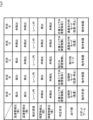
- FIG. 9 shows an example of the correspondence between the detection states of the hot water pipe detection sensor 110 and the obstacle detection sensor 109 and the modes of each part.
- the hot water pipe detection sensor 110 on the front side is in the detection state
- the hot water pipe detection sensor 110 on the rear side is in the detection state.
- the control device 120 switches the obstacle detection area by the obstacle detection sensor 109 to the in-lane pattern Pb.
- the front obstacle detection sensor 109 is in an undetected state, and the rear obstacle detection sensor 109 is not detected. state.
- control device 120 determines that the self-propelled work robot 100 exists in the work area R1 and that there are obstacles around the self-propelled work robot 100, in this case, in front and behind the self-propelled work robot 100. It is determined that there is no such situation.
- control device 120 switches the traveling mode of the traveling section 105 to the harvesting mode to enable traveling at a predetermined high speed. Further, the control device 120 switches the operation mode of the robot arm 102 to the operation permission mode to enable the robot arm 102 to operate. Thereby, the self-propelled working robot 100 can perform harvesting work using the robot arm 102 within the working area R1.
- situation pattern B when the obstacle detection area by the obstacle detection sensor 109 is switched to the in-lane pattern Pb, the front obstacle detection sensor 109 is in the detection state, and the rear obstacle detection area is switched to the in-lane pattern Pb.
- the object detection sensor 109 is in an undetected state.
- control device 120 detects a state in which the self-propelled work robot 100 exists in the work area R1 and there is an obstacle around the self-propelled work robot 100, in this case, in front of the self-propelled work robot 100. It is determined that
- control device 120 switches the traveling mode of the traveling section 105 to the harvesting mode to enable traveling at a predetermined high speed.
- the control device 120 switches the travel mode of the travel unit 105 to the harvesting mode, but does not control the self-propelled work robot 100.
- the moving speed is adjusted to a predetermined low speed, and depending on the situation, the self-propelled working robot 100 is stopped from traveling.
- control device 120 switches the operation mode of the robot arm 102 to the operation restriction mode to limit the operation of the robot arm 102. Thereby, it is possible to avoid the robot arm 102 from operating and coming into contact with an obstacle. At this time, the control device 120 can, for example, slow down the operation speed of the robot arm 102 or stop the operation of the robot arm 102. Note that the control device 120 is configured to control, for example, slowing down the operating speed of the robot arm 102 or temporarily stopping the operation of the robot arm 102, while setting the operation mode of the robot arm 102 to the operation permissible mode. It's okay.
- the hot water pipe detection sensor 110 on the front side is in the detection state
- the hot water pipe detection sensor 110 on the rear side is in the non-detection state.
- one of the two hot water pipe detection sensors 110 at the front and rear of the self-propelled working robot 100 is in an undetected state. Therefore, if the self-propelled work robot 100 is in the middle of moving from outside the work area R1 to inside the work area R1, or in the middle of moving from inside the work area R1 to outside the work area R1, can be judged.
- the control device 120 switches the obstacle detection area by the obstacle detection sensor 109 to the in-lane pattern Pb. That is, the control device 120 prevents obstacles from occurring as long as the entire self-propelled work robot 100 does not move outside the work area R1, in other words, as long as a part of the self-propelled work robot 100 remains within the work area R1.
- the vehicle is configured to switch the obstacle detection area by the object detection sensor 109 to the in-lane pattern Pb.
- the control device 120 may switch the detection area of the obstacle by the obstacle detection sensor 109 to the out-of-lane pattern Pa when at least a part of the obstacle moves outside the work area R1.
- the front obstacle detection sensor 109 is in an undetected state, and the rear obstacle detection sensor 109 is not detected. state.
- control device 120 can control the state in which the self-propelled work robot 100 is moving from outside the work area R1 to inside the work area R1, or while the self-propelled work robot 100 is moving from inside the work area R1 to outside the work area R1. It is determined that the state is Further, the control device 120 determines that there are no obstacles around the self-propelled working robot 100, in this case, in front and behind the self-propelled working robot 100.
- control device 120 switches the traveling mode of the traveling section 105 to the transition mode to enable traveling at a predetermined low speed. Further, the control device 120 switches the operation mode of the robot arm 102 to the operation restriction mode to limit the operation of the robot arm 102. As a result, the self-propelled work robot 100 cannot move from outside the work area R1 to inside the work area R1, or from inside the work area R1 to outside the work area R1, while the movement of the robot arm 102 is restricted. It can be carried out. Note that at this time, the control device 120 may maintain, for example, a state in which the operation of the robot arm 102 is stopped.
- the self-propelled working robot 100 It is estimated that the object is in the middle of moving from outside the work area R1 into the inside of the work area R1, or in the middle of moving from inside the work area R1 to outside the work area R1. Therefore, it is preferable that the control device 120 performs the same control as in situation pattern C described above in this case as well.
- the hot water pipe detection sensor 110 on the front side is in an undetected state
- the hot water pipe detection sensor 110 on the rear side is in an undetected state.
- both the front and rear hot water pipe detection sensors 110 of the self-propelled working robot 100 are in a non-detection state. Therefore, it can be determined that the self-propelled working robot 100 is present in an area other than the work area R1. Therefore, the control device 120 switches the obstacle detection area by the obstacle detection sensor 109 to the out-of-lane pattern Pa.
- the front obstacle detection sensor 109 is in an undetected state, and the rear obstacle detection sensor 109 is not detected. state.
- control device 120 controls the self-propelled working robot 100 when the self-propelled working robot 100 exists in an area other than the work area R1, for example, in a passage in the field 10, and the area around the self-propelled working robot 100, in this case, the self-propelled working robot 100 It is determined that there are no obstacles in front or behind the work robot 100 in the direction of movement.
- control device 120 switches the traveling mode of the traveling section 105 to the aisle traveling mode to enable traveling at a predetermined low speed. Further, the control device 120 switches the operation mode of the robot arm 102 to the operation restriction mode to limit the operation of the robot arm 102. Thereby, the self-propelled work robot 100 can travel in areas other than the work area R1 while the movement of the robot arm 102 is restricted. Note that at this time, the control device 120 may maintain, for example, a state in which the operation of the robot arm 102 is stopped.
- the obstacle detection area by the obstacle detection sensor 109 is switched to the out-of-lane pattern Pa, the front obstacle detection sensor 109 is in the detection state, and the obstacle detection area on the rear side is in the detection state.
- the object detection sensor 109 is in an undetected state.
- the control device 120 controls the self-propelled working robot 100, It is determined that there is an obstacle in front of the robot 100 in the direction of movement.
- control device 120 switches the traveling mode of the traveling section 105 to the aisle traveling mode to enable traveling at a predetermined low speed.
- the control device 120 may switch the traveling mode of the traveling unit 105 to the aisle traveling mode, but may The movement of the type work robot 100 is stopped.
- control device 120 switches the operation mode of the robot arm 102 to the operation restriction mode to limit the operation of the robot arm 102. Thereby, it is possible to avoid the robot arm 102 from operating and coming into contact with an obstacle. At this time, the control device 120 can maintain, for example, a state in which the operation of the robot arm 102 is stopped.
- the robot arm 102 is configured to be operable in a plurality of operation modes
- the robot main body 101 is provided with the robot arm 102
- the robot main body 101 is configured to operate in a plurality of operation modes.
- a switching unit 124 is provided.
- the operation mode of the robot arm 102 can be switched as appropriate depending on the detection status of the hot water pipe 12 by the hot water pipe detection sensor 110.
- the robot arm 102 can be The operation mode of the device can be switched between the operation permission mode and the operation restriction mode with high accuracy.
- the hot water pipe 12 which is an example of a target, extends along the traveling direction of the robot main body 101 and the entire self-propelled working robot 100 by the traveling section 105.
- the hot water pipe 12 in the area where the hot water pipe 12 extends, the hot water pipe 12 can be continuously detected as the self-propelled working robot 100 advances, and a situation where the hot water pipe 12 cannot be detected can be prevented. This can be avoided.
- the operation mode of the robot arm 102 can be switched to the operation permissible mode within the area. It is possible to continue to maintain the state that has been maintained.
- the robot main body 101 and by extension the entire self-propelled working robot 100, travels over the target hot water pipe 12 by the traveling section 105.
- the target hot water pipe 12 exists directly below the traveling self-propelled working robot 100, the hot water pipe 12 can be detected even more easily.
- the detection area switching unit 125 switches the detection area by the obstacle detection sensor 109 according to the detection status of the hot water pipe 12 by the hot water pipe detection sensor 110.
- the hot water pipe 12 In a state where the hot water pipe 12 is detected by the hot water pipe detection sensor 110, there is a high possibility that the self-propelled working robot 100 exists within the work area R1. Therefore, by switching the obstacle detection area by the obstacle detection sensor 109 to an area suitable for work, in this case, the in-lane pattern Pb, for example, the cultivation equipment 11a or the support member 11b may be detected as an obstacle. can be avoided.
- the hot water pipe 12 is not detected by the hot water pipe detection sensor 110, there is a high possibility that the self-propelled working robot 100 exists in an area other than the work area R1. Therefore, by switching the obstacle detection area by the obstacle detection sensor 109 to an area suitable for non-work, in this case to the outside lane pattern Pa, for example, a person existing in an area other than the work area R1 can be detected as an obstacle. This can be detected and safety can be improved.
- the robot arm 102 can be switched to at least a motion permissible mode in which motion is permitted and a motion restriction mode in which motion is restricted. Then, when the hot water pipe detection sensor 110 detects the hot water pipe 12, the operation mode switching unit 124 switches the operation mode of the robot arm 102 from the operation restriction mode to the operation permission mode.
- the hot water pipe detection sensors 110 are provided at the front and rear parts of the robot main body 101 in the direction of movement.
- the entire self-propelled working robot 100 is present on the hot water pipe 12, that is, within the work area R1. This can be determined with high accuracy.
- the self-propelled working robot 100 is entirely or partially outside the work area R1. It can be determined with high accuracy.
- the robot arm 102 operates outside the work area R1. It is possible to avoid putting it away, and it is possible to further improve safety.
- the self-propelled working robot 100 includes a form switching unit 126 that switches the form of the robot arm 102 according to the detection status of the hot water pipe 12 by the hot water pipe detection sensor 110. Then, the robot arm 102 selects a detection mode that is set as a mode to be taken or a recommended mode when the hot water pipe detection sensor 110 detects the hot water pipe 12, and It is possible to switch to a non-detection mode that is set as a mode to be taken when 12 is not detected or a recommended mode. Then, when the hot water pipe detection sensor 110 does not detect the hot water pipe 12 and the robot arm 102 is switched to the detection state, the form switching unit 126 changes the form of the robot arm 102 to the detection state. to switch to non-detection mode.
- the robot arm 102 when the robot arm 102 is switched to the detection mode when the hot water pipe detection sensor 110 is not detecting the hot water pipe 12, The robot main body 101 is caused to travel by the traveling unit 105 until the hot water pipe detection sensor 110 detects the hot water pipe 12, and then the form of the robot arm 102 is switched from the detection state to the non-detection state.
- the hot water pipe detection sensor 110 does not detect the hot water pipe 12 and the robot arm 102 is switched to the detection mode, the hot water pipe detection sensor 110 will not detect the hot water pipe 12 until the hot water pipe detection sensor 110 detects the hot water pipe 12. It is preferable to switch the form of the robot arm 102 after the robot main body section 101 is driven by the traveling section 105, that is, after the self-propelled working robot 100 is moved into the work area R1. Thereby, the robot arm 102 can be prevented from coming into contact with a person during shape deformation, and safety can be improved.
- the self-propelled working robot 100 includes a harvesting tool 103 provided on the robot arm 102 and a disinfection unit 108 that disinfects the harvesting tool 103. Therefore, as the non-detection state, for example, a state in which the harvesting tool 103 is moved into the disinfection unit 108 may be set.
- the harvesting tool 103 is moved into the disinfection unit 108, it is easier to avoid the harvesting tool 103 coming into contact with people, and safety can be further improved. Further, the robot arm 102 is set in the non-detection state mainly when the robot arm 102 is not performing any work. Therefore, by adopting a configuration in which the harvesting tool 103 is moved into the disinfection unit 108 as the non-detection mode, the harvesting tool 103 can be disinfected by the disinfection unit 108 during non-operation, and the disinfection work can be carried out efficiently. It can be carried out.
- the self-propelled working robot 100 includes a camera 104 provided on the robot arm 102. Therefore, as the non-detection mode, for example, a mode may be set in which the camera 104 moves to a position where a predetermined photographic object can be photographed.
- the robot arm 102 is in the non-detection state mainly when the robot arm 102 is not performing any work, and when the robot arm 102 is not working, the self-propelled working robot 100 is in the non-detection state. It is assumed that the vehicle will be driven in the following areas. Therefore, by adopting a configuration in which the camera 104 moves to a position where it can photograph a predetermined object to be photographed, such as the trace line 13 or the markers 14 and 15, as the non-detection mode, the self-propelled It is possible to easily photograph an object to be photographed when the working robot 100 is traveling, and it is possible to easily support the traveling of the self-propelled working robot 100 when not working.
- a predetermined object to be photographed such as the trace line 13 or the markers 14 and 15
- the traveling unit 105 is a driving wheel that moves the robot main body 101 and the entire self-propelled working robot 100 according to the detection status of the hot water pipe 12 by the hot water pipe detection sensor 110.
- the rotation speed of 106 can be switched.
- the driving wheels are driven at the same rotational speed in the case where the large wheel portion 106a is mainly used to travel in an area other than the work area R1, and when the small wheel portion 106b is mainly used to travel over the hot water pipe 12 in the work area R1.
- the movement speed of the self-propelled work robot 100 when traveling in an area other than the work area R1 becomes relatively faster, and the movement speed of the self-propelled work robot 100 when traveling within the work area R1 becomes relatively faster. Movement speed becomes relatively slow.
- the running speed of the self-propelled working robot 100 becomes excessively slow. It is possible to avoid putting it away, and it is possible to suppress the occurrence of a situation where the work time becomes longer.
- the driving speed of the drive wheels is increased, the distance traveled per unit time becomes longer, so it is conceivable to widen the obstacle detection area.
- the rotation speed of the drive wheel 106 is increased, the rotation speed of the small wheel portion 106b is increased, not the large wheel portion 106a.
- the overall movement speed is not that much faster.
- the self-propelled work robot 100 if the rotation speed of the drive wheels 106 is increased but the detection area of obstacles by the obstacle detection sensor 109 is also widened, for example, the self-propelled work robot 100 may Even though the type work robot 100 is sufficiently far from the end of the work area R1, there is a risk that a wall or the like existing at the end of the work area R1 will be detected as an obstacle by the obstacle detection sensor 109. be.
- the self-propelled work robot 100 is controlled to reduce its movement speed or stopped, even though the self-propelled work robot 100 has not approached the edge of the work area R1. There is a concern that control may be carried out that causes
- the self-propelled working robot 100 is configured to switch the detection area of the obstacle by the obstacle detection sensor 109 to the in-lane pattern Pb when the obstacle exists within the work area R1. Therefore, even if the traveling speed of the self-propelled work robot 100 in the work area R1 is increased, the obstacle detection area by the obstacle detection sensor 109 will not be too wide to be suitable for traveling in the work area R1. Can be set in the area. Therefore, it is possible to avoid controlling the self-propelled working robot 100 from slowing down or stopping it even though there is still a distance to the end of the working area R1.
- the self-propelled working robot 100 includes a safety monitoring unit 123 that monitors whether the behavior of the entire self-propelled working robot 100 including at least the robot arm 102 and the traveling unit 105 is in a safe state.
- the safety monitoring section 123 functions as a control section that controls the behavior of the entire self-propelled working robot 100 including at least the robot arm 102 and the traveling section 105.
- the self-propelled working robot 100 can perform work and travel in a safe state based on control by the control unit.
- safety monitoring unit 123 by configuring the safety monitoring unit 123 with a control unit that has obtained predetermined safety certification, safety can be further ensured. Furthermore, by configuring various sensors such as the hot water pipe detection sensor 110 and the obstacle detection sensor 109 with sensors that have obtained predetermined safety certification, safety can be further ensured. . Further, by configuring other components constituting the self-propelled working robot 100 with components that have obtained predetermined safety certification, safety can be further ensured. Note that various safety certification standards such as those established by the International Organization for Standardization (ISO) can be adopted as the safety certification.
- ISO International Organization for Standardization
- the self-propelled working robot 100 includes a robot arm 102 that can perform agricultural work, it may also be configured to include a robot arm that can perform tasks other than agricultural work.
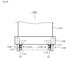
- the self-propelled working robot 100 is configured to include hot water pipe detection sensors 110 on both sides of the robot body 101 in the lateral direction.
- the two hot water pipe detection sensors 110 can detect the inclination of the hot water pipe 12 or the width dimension of the hot water pipe 12 in the horizontal direction.
- the width dimension of the hot water pipe 12 can also be defined as a dimension in a direction orthogonal to the longitudinal direction of the hot water pipe 12.
- the width dimension of the hot water pipe 12 in the horizontal direction may become narrower or wider due to factors such as, for example, the hot water pipe 12 being tilted, aging or damage to the hot water pipe 12, and the like. If a change in the inclination or width of the hot water pipe 12 is detected, the control device 120 may, for example, reduce the traveling speed of the self-propelled work robot 100, stop traveling, or cause an error.
- the error notification may be, for example, displayed on the display of the operation input unit included in the self-propelled working robot 100, lit or blinking a warning lamp, or notified by voice or sound via a speaker or the like. You may.
- the present disclosure is not limited to the plurality of embodiments described above, and can be modified and expanded as appropriate without departing from the gist thereof.
- the self-propelled working robot 100 can be configured by appropriately selecting and combining the plurality of embodiments described above.
- the target is not limited to the hot water pipe 12, but may be another element that can be detected by the self-propelled working robot 100 in the field 10, for example.
- the target may be, for example, a predetermined object provided at the entrance of the work area R1.
- the self-propelled work robot 100 when it detects a predetermined object, it may maintain the detection state, ie, latch it, and when it detects the predetermined object again, it may switch to the non-detection state, ie, the non-latching state.
- the target detection unit may be configured to detect the target not by a non-contact type switch, but may be configured to detect the target using, for example, a contact type switch, a switch using communication or light, or a configuration that detects the target using RFID.
- the target may be detected by recognition of a code or the like by the camera 104. That is, various configurations can be applied as long as the configuration can detect the target using some method.
- the target detection unit may be configured to be able to detect the target while the self-propelled working robot 100 is running, or may be configured to be able to detect the target while the self-propelled working robot 100 is stopped. good.
- the self-propelled working robot 100 may be configured to allow the robot arm 102 to operate at positions other than the position where the target is detected by the target detection unit, or only at the position where the target is detected by the target detection unit. The configuration may be such that the robot arm 102 is allowed to operate.
- the self-propelled working robot 100 may be configured to allow the robot arm 102 to operate on the condition that a sufficiently safe state is ensured by the safety monitoring unit 123, for example.
- the number of target detection units mounted on one self-propelled working robot 100 is not limited to two, and may be one or three or more.
- the placement position of the target detection unit is not limited to the front or rear of the self-propelled working robot 100, but may be, for example, on the left side or right side, or on the top or bottom. However, other parts may be used.
- the number of obstacle detection units mounted on one self-propelled working robot 100 is not limited to two, and may be one or three or more.
- the location of the obstacle detection unit is not limited to the front or rear of the self-propelled working robot 100, but may be placed on the left or right side, or on the top or bottom. It may also be in other parts. Further, the present disclosure can also be applied to self-propelled working robots that perform tasks other than agricultural work.
- control unit and the method described in the present disclosure may be implemented by a dedicated computer provided by configuring a processor and memory programmed to perform one or more functions embodied by a computer program. It may be realized.
- controller and techniques described in this disclosure may be implemented by a dedicated computer provided by configuring the processor with one or more dedicated hardware logic circuits.
- control unit and the method described in the present disclosure may be implemented using a combination of a processor and memory programmed to execute one or more functions and a processor configured with one or more hardware logic circuits. It may be implemented by one or more dedicated computers configured.
- the computer program may also be stored as instructions executed by a computer on a computer-readable non-transitory tangible storage medium.
- the present disclosure further includes the following inventions.
- an operating section (102) configured to be operable in a plurality of operating modes; a robot main body section (101) in which the operating section is provided; a traveling section (105) that causes the robot main body to travel; a target detection unit (110) configured to be able to detect a predetermined target; an operation mode switching unit (124) that switches the operation mode of the operation unit according to the detection status of the target by the target detection unit;
- the operation unit is switchable between an operation permission mode in which operation is permitted and an operation restriction mode in which operation is restricted; 5.
- the operation mode switching section switches the operation mode of the operation section from the operation restriction mode to the operation permission mode when the target detection section detects the target.
- [Claim 6] The self-propelled working robot according to any one of claims 1 to 5, wherein the target detection section is provided at a front portion and a rear portion of the robot main body portion in a traveling direction.
- [Claim 7] comprising a form switching unit (126) that switches the form of the operating unit depending on the detection status of the target by the target detection unit;
- the operating unit includes a detection mode that is set as a configuration that should be taken when the target detection unit is detecting the target, and a configuration that is set as a configuration that should be taken when the target detection unit is not detecting the target.
- the mode switching section changes the mode of the operating section from the detection mode to the non-detection mode when the operating section is switched to the detection mode when the target detection section does not detect the target.
- the self-propelled working robot according to any one of claims 1 to 6, wherein the self-propelled working robot switches to a detection mode.
- the mode switching section is configured to bring the target detection section into a state where the target detection section detects the target when the operation section is switched to the detection mode when the target detection section does not detect the target. 8.
- a working part (103) that is provided in the operating part and performs a predetermined work; a disinfection section (108) for disinfecting the working section; Equipped with 9.
- the non-detection state is a state in which the working part has moved into the disinfection part.
- [Claim 10] comprising an imaging unit (104) provided in the operating unit, 9.
- the traveling section switches the rotational speed of wheels for moving the robot body according to the detection status of the target by the target detection section. .
- a safety monitoring unit (123) that monitors whether the behavior of the operating unit and the traveling unit is in a safe state.
Landscapes
- Engineering & Computer Science (AREA)
- Robotics (AREA)
- Mechanical Engineering (AREA)
- Remote Sensing (AREA)
- Aviation & Aerospace Engineering (AREA)
- Radar, Positioning & Navigation (AREA)
- Environmental Sciences (AREA)
- Physics & Mathematics (AREA)
- General Physics & Mathematics (AREA)
- Automation & Control Theory (AREA)
- Life Sciences & Earth Sciences (AREA)
- Human Computer Interaction (AREA)
- Manipulator (AREA)
Abstract
自走式作業ロボット(100)は、複数の動作モードにより動作可能に構成されている動作部(102)と、前記動作部が設けられているロボット本体部(101)と、前記ロボット本体部を走行させる走行部(105)と、所定のターゲットを検出可能に構成されているターゲット検出部(110)と、前記ターゲット検出部による前記ターゲットの検出状況に応じて前記動作部の動作モードを切り替える動作モード切替部(124)と、を備える。
Description
本出願は、2022年5月11日に出願された日本出願番号2022-078208号に基づくもので、ここにその記載内容を援用する。
本開示は、自走式作業ロボットに関する。
近年、例えば農作物を生育する圃場内において、農作物に対する例えば収穫作業などといった作業を自走式作業ロボットによって行う技術が検討されている。この種の自走式作業ロボットとして例えば特許文献1に開示されている自走式作業ロボットは、作業を行うためのロボットアームを動作部として備えている。
この種の自走式作業ロボットにおいては、作業を行うロボットアームを、動作が許容される動作許容モード、および、動作が制限される動作制限モードに切り替え可能に構成することが考えられている。ここで、例えば圃場内には、自走式作業ロボットによって作業を行うことを想定して設定されている作業エリア、および、自走式作業ロボットによって作業を行わないことを想定して設定されている非作業エリアが存在している。そして、非作業エリアにおいては、自走式作業ロボットが走行するほか、人が存在する可能性もある。そのため、自走式作業ロボットが非作業エリア内に存在している状態においては、ロボットアームを動作制限モードに確実に切り替えることで、ロボットアームが意図せず動作して人に接触してしまうことを抑制することができ、安全性の向上を図ることができる。
そこで、本開示は、自走式作業ロボットが存在する領域に応じて動作部の動作モードを精度良く切り替えることができるようにした構成を提供する。
本開示の一態様において、自走式作業ロボットは、複数の動作モードにより動作可能に構成されている動作部と、前記動作部が設けられているロボット本体部と、前記ロボット本体部を走行させる走行部と、所定のターゲットを検出可能に構成されているターゲット検出部と、前記ターゲット検出部による前記ターゲットの検出状況に応じて前記動作部の動作モードを切り替える動作モード切替部と、を備える。
本開示に係る自走式作業ロボットによれば、ターゲット検出部によるターゲットの検出状況に応じて動作部の動作モードを切り替えることができる。これにより、例えば動作部の動作モードを切り替えたい領域内にターゲットを設けておくことで、自走式作業ロボットが存在する領域に応じて動作部の動作モードを精度良く切り替えることができる。
本開示についての上記目的およびその他の目的、特徴や利点は、添付の図面を参照しながら下記の詳細な記述により、より明確になる。その図面は、
図1は、第1実施形態に係る圃場の構成例を概略的に示す図であり、
図2は、第1実施形態に係る自走式作業ロボットの構成例を概略的に示す図であり、
図3は、第1実施形態に係るものであり、障害物の検出領域がレーン外パターンに切り替えられている状態例を概略的に示す図であり、
図4は、第1実施形態に係るものであり、障害物の検出領域がレーン内パターンに切り替えられている状態例を概略的に示す図であり、
図5は、第1実施形態に係る温湯管検出センサの構成例を概略的に示す斜視図であり、
図6は、第1実施形態に係るものであり、非検出状態における温湯管検出センサの状態例を概略的に示す図であり、
図7は、第1実施形態に係るものであり、検出状態における温湯管検出センサの状態例を概略的に示す図であり、
図8は、第1実施形態に係る制御装置の構成例を概略的に示すブロック図であり、
図9は、第1実施形態に係るものであり、センサ類の検出状態と各部のモードとの対応関係の一例を示す図であり、
図10は、第2実施形態に係るものであり、温湯管が傾いていない状態例を概略的に示す図であり、
図11は、第2実施形態に係るものであり、温湯管が傾いている状態例を概略的に示す図である。
以下、本開示の自走式作業ロボットに係る複数の実施形態について図面を参照しながら説明する。なお、複数の実施形態において実質的に同一の要素には同一の符号を付して、その説明を省略する。
(第1実施形態)
本開示に係る自走式作業ロボット100は、例えば図1に例示する圃場10内において農作物Tに対する収穫作業などといった作業を行う用途に利用可能である。圃場10は、例えばビニールハウスや植物工場などと称される場合もある。圃場10内には、この場合、複数の栽培部11、複数の温湯管12、複数のトレースライン13などが設けられている。
本開示に係る自走式作業ロボット100は、例えば図1に例示する圃場10内において農作物Tに対する収穫作業などといった作業を行う用途に利用可能である。圃場10は、例えばビニールハウスや植物工場などと称される場合もある。圃場10内には、この場合、複数の栽培部11、複数の温湯管12、複数のトレースライン13などが設けられている。
栽培部11は、それぞれ複数の栽培設備11aを有している。栽培設備11aは、自走式作業ロボット100による収穫対象である農作物Tを栽培するための設備である。栽培設備11aは、栽培部11内において、例えば柱などといった支持部材11bによって支持されている。1つの栽培部11内においては、複数の栽培設備11aが栽培部11の長手方向に沿って直線上に配置されている。1つの栽培部11は、例えば十数m~数十m程度などといった所定距離にわたって一方向へ延びている。圃場10内には、複数の栽培部11が相互に平行となるように配置されている。また、複数の栽培部11は、相互に間隔を有して配置されている。この場合、複数の栽培部11間の間隔は、等間隔となっている。なお、複数の栽培部11間の間隔は、不等間隔であってもよい。
温湯管12は、隣接する2つの栽培部11の間に設けられている。温湯管12は、長尺な管状材を、いわゆるU字状に折り曲げることにより構成されたものであり、それぞれ栽培部11に沿って伸びている。温湯管12内には図示しない給湯設備から温水を流すことが可能である。温湯管12内を温水が流れることにより、圃場10内の温度、特に、栽培部11の周辺領域の温度を適温に温めることができる。温湯管12は、所定のターゲットの一例として圃場10内に備えられている。
トレースライン13は、例えば圃場10の床面に貼り付け、印刷、描画することなどにより設置されており、複数の温湯管12の間を繋いでいる。圃場10内のうち温湯管12が設けられている領域は、作業エリアR1として定義されている。また、圃場10内のうち作業エリアR1以外の領域であって、且つ、複数の作業エリアR1を接続する領域、この場合、トレースライン13が設けられている領域は、非作業エリアR2として定義されている。非作業エリアR2は、非作業時における自走式作業ロボット100が走行する通路に含まれている。
作業エリアR1は、基本的には、自走式作業ロボット100によって作業を行うことを想定して設けられている領域であり、且つ、例えば圃場10の管理者や自走式作業ロボット100の使用者などといった人が存在しないことを想定して設けられている領域である。即ち、作業エリアR1は、基本的には、自走式作業ロボット100と人が共存しないことを想定して設けられている非共存エリアとして定義することができる。
一方、非作業エリアR2は、自走式作業ロボット100によって作業を行わないことを想定して設けられている領域であり、且つ、例えば圃場10の管理者や自走式作業ロボット100の使用者などといった人が存在することを想定して設けられている領域である。即ち、非作業エリアR2は、基本的には、自走式作業ロボット100と人が共存することを想定して設けられている共存エリアとして定義することができる。
また、圃場10内には、複数のマーカー14,15が備えられている。この場合、マーカー14,15は、作業エリアR1と非作業エリアR2との境界点、または、トレースライン13の分岐点に位置して設けられている。より詳細に説明すると、マーカー14は、この場合、作業エリアR1と非作業エリアR2との境界点付近において、非作業エリアR2内のうち作業エリアR1に入る手前直前の位置に設けられている。また、マーカー15は、複数の作業エリアR1を横切るようにして直線状に設けられたトレースライン13から、それぞれの作業エリアR1へ分岐する分岐点に位置して設けられている。
マーカー14,15は、例えば圃場10の床面に貼り付け、印刷、描画することなどにより設置されており、自走式作業ロボット100が備えているカメラ104によって撮影可能である。なお、マーカー14,15は、例えば、磁気、電波、画像、音波、その他の方法により非接触によって情報の伝達を行うことができる情報伝達媒体によっても構成することができる。具体的には、マーカー14,15は、例えばRFID、二次元コード、磁気マーカーなどによって構成することができる。
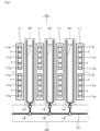
次に、自走式作業ロボット100の構成例について詳細に説明する。図2に例示するように、自走式作業ロボット100は、そのベース部分を構成するロボット本体部101の上部にロボットアーム102を備えている。ロボットアーム102は、動作部の一例である。ロボットアーム102は、複数の可動アームが組み合わされた構成、いわゆる多軸型の構成となっている。よって、ロボットアーム102としては、いわゆる6軸型のロボットアームや4軸型のロボットアームなどを適用することができる。
そして、ロボットアーム102は、その先端部に収穫ツール103およびカメラ104を備えている。収穫ツール103は、所定の動作として、この場合、農作物Tの収穫作業を行う作業部の一例として備えられている。ロボットアーム102は、このような農作物収穫用の収穫ツール103を備えることにより、農作業の一例である収穫作業を実行可能な動作部として構成されている。なお、ロボットアーム102に備えることができる作業部は、収穫ツール103に限られるものではなく、例えば、収穫作業以外の農作業を行うツールや、農作業以外の作業を行うツールであってもよい。
カメラ104は、撮影部の一例であり、例えば圃場10内に設けられているトレースライン13やマーカー14,15などを撮影可能に構成されている。自走式作業ロボット100は、カメラ104によって撮影されたトレースライン13やマーカー14,15などに基づいて当該自走式作業ロボット100の現在位置を判定しながら自律的に走行することが可能である。
また、ロボットアーム102は、複数の動作モードにより動作可能に構成されている。この場合、ロボットアーム102は、少なくとも、動作が許容される動作許容モード、および、動作が制限される動作制限モードに切り替え可能に構成されている。
動作許容モードは、ロボットアーム102が複数の可動アームを動かしながら収穫ツール103により農作物Tの収穫動作を行ったりカメラ104により撮影動作を行ったりすることが許容される動作モードである。
一方、動作制限モードは、ロボットアーム102が複数の可動アームを動かしながら収穫ツール103により農作物Tの収穫動作を行ったりカメラ104により撮影動作を行ったりすることが制限される動作モードである。動作制限モードによる制限は、この場合、ロボットアーム102の動作を規制あるいは停止させることを想定している。但し、例えば十分な安全性が確保されるのであれば、動作制限モードによる制限は、ロボットアーム102の動作を若干許容するように設定してもよい。
また、自走式作業ロボット100は、ロボット本体部101の下部に走行部105を備えている。走行部105は、一対の駆動輪106および複数の従動輪107を備えている。駆動輪106は、車輪の一例である。詳しい図示は省略するが、駆動輪106は、例えば減速機を介してモータなどの駆動源により回転されるように構成されている。走行部105は、主として駆動輪106を回転させることによりロボット本体部101ひいては自走式作業ロボット100全体を走行させる。従動輪107は、駆動輪106によってロボット本体部101が走行することに伴い回転し、当該ロボット本体部101の走行、ひいては、自走式作業ロボット100全体の走行をサポートして安定化させる。
なお、ロボット本体部101は、全体として長尺な概ね矩形状をなしており、走行部105は、ロボット本体部101ひいては自走式作業ロボット100全体を当該ロボット本体部101の長手方向に沿って走行させるようになっている。即ち、ロボット本体部101ひいては自走式作業ロボット100全体の進行方向は、この場合、ロボット本体部101の長手方向に沿う方向となっている。
また、自走式作業ロボット100のロボット本体部101は、作業エリアR1内においては、走行部105により温湯管12上を走行する。また、自走式作業ロボット100は、作業エリアR1内においては、ロボット本体部101の長手方向を温湯管12の延伸方向に沿わせて走行する。よって、圃場10内において、温湯管12は、走行部105によるロボット本体部101の進行方向に沿って延伸した状態となっている。
また、自走式作業ロボット100は、消毒用ユニット108を備えている。消毒用ユニット108は、消毒部の一例であり、上面が開放した消毒ボックス内において、図示しないノズルから消毒液を噴射可能に構成されている。消毒用ユニット108は、ロボットアーム102が先端部の収穫ツール103を消毒用ユニット108の消毒ボックス内に移動させた状態で消毒液を噴射することにより、収穫ツール103を消毒可能に構成されている。
また、自走式作業ロボット100は、複数、この場合、2つの障害物検出センサ109を備えている。障害物検出センサ109は、ロボット本体部101の進行方向における前部および後部に、それぞれ分散して配置されている。障害物検出センサ109は、ロボット本体部101の周囲に存在する障害物を検出するための障害物検出部の一例として備えられている。障害物検出センサ109は、例えば、周囲に存在する障害物を検出するレーザーセンサや超音波センサなどによって構成されている。障害物検出センサ109が検出する障害物としては、例えば、圃場10内に存在する栽培設備11a、支持部材11b、人、各種の設備などが想定される。なお、障害物検出センサ109は、所定の安全認証を取得したセンサにより構成することが望ましい。
また、自走式作業ロボット100は、複数、この場合、2つの温湯管検出センサ110を備えている。温湯管検出センサ110も、ロボット本体部101の進行方向における前部および後部に、それぞれ分散して配置されている。温湯管検出センサ110は、ターゲット検出部の一例として備えられており、この場合、圃場10内に設けられているターゲットの一例である温湯管12を検出可能に構成されている。温湯管検出センサ110の構成や機能などについての詳細な説明は後述する。なお、温湯管検出センサ110は、所定の安全認証を取得したセンサにより構成することが望ましい。
また、自走式作業ロボット100は、制御装置120を備えている。制御装置120は、例えばマイクロコンピュータなどを主体として構成されており、制御プログラムや設定データなどに基づいて自走式作業ロボット100の動作全般を制御する。
図3および図4に例示するように、2つの障害物検出センサ109のうち一方の障害物検出センサ109は、ロボット本体部101の前部において当該ロボット本体部101の短手方向における一端側に配置されている。また、2つの障害物検出センサ109のうち他方の障害物検出センサ109は、ロボット本体部101の後部において当該ロボット本体部101の短手方向における他端側に配置されている。
また、走行部105が備えている駆動輪106は、大輪部106aおよび小輪部106bを同軸状に組み合わせた構成となっている。大輪部106aは、駆動輪106の本体部分を構成する大径の車輪となっている。一方、小輪部106bは、大輪部106aよりも小径の車輪となっている。大輪部106aおよび小輪部106bの回転軸は共通であり、従って、大輪部106aおよび小輪部106bは一体的に回転するようになっている。
自走式作業ロボット100は、圃場10内において作業エリアR1以外の領域を走行する場合には、大輪部106aを圃場10の床面に接触させた状態で走行する。このとき、小輪部106bは、圃場10の床面に接触しておらず離間している。よって、自走式作業ロボット100は、圃場10内において作業エリアR1以外の領域を走行する場合には、主として大輪部106aの回転により走行する。
しかし、自走式作業ロボット100は、圃場10内において作業エリアR1内を走行する場合には、上述した通り、温湯管12上を走行する。このとき、図4に例示するように、自走式作業ロボット100は、小輪部106bを温湯管12の上面に接触させた状態で走行する。また、このとき、大輪部106aは、圃場10の床面に接触しておらず離間している。よって、自走式作業ロボット100は、圃場10内において作業エリアR1内を走行する場合には、主として小輪部106bの回転により走行する。
次に、温湯管検出センサ110の構成例について、さらに詳細に説明する。図5に例示するように、温湯管検出センサ110は、非接触型スイッチ111および遮蔽板112を備えている。非接触型スイッチ111は、例えば光学的あるいは磁気的な状態変化に応じてオン状態およびオフ状態が切り替わる構成である。遮蔽板112は、非接触型スイッチ111の側方において上下方向に回動可能に設けられている。
この場合、遮蔽板112は、図6に例示するように非接触型スイッチ111を覆わず露出させる状態となる非検出位置と、図7に例示するように非接触型スイッチ111を覆う状態となる検出位置との間で回動可能となっている。
また、遮蔽板112は、例えば圧縮コイルばねなどによって構成される付勢部材113によって、図7に例示する検出位置側から図6に例示する非検出位置側に回動するように付勢されている。また、遮蔽板112の下端部には支持車輪114が回転可能に設けられている。
図6に例示するように、自走式作業ロボット100が温湯管12上に存在しない状態においては、遮蔽板112は、付勢部材113による付勢力を受けて非検出位置に回動する。これにより、非接触型スイッチ111は、温湯管12を検出していない状態である非検出状態となる。一方。、図7に例示するように、自走式作業ロボット100が温湯管12上に存在する状態においては、遮蔽板112は、支持車輪114を介して温湯管12によって上方に押し込まれるようになり、付勢部材113による付勢力に抗しながら検出位置に回動する。これにより、非接触型スイッチ111は、温湯管12を検出した状態である検出状態となる。
このような構成により、温湯管検出センサ110は、非接触型スイッチ111が検出状態あるいは非検出状態に切り替わることに基づき、ターゲットの一例である温湯管12を検出可能に構成されている。
次に、自走式作業ロボット100の制御系の構成例について、さらに詳細に説明する。図8に例示するように、制御装置120は、制御プログラムを実行することにより、動作制御部121、走行制御部122、安全監視部123、動作モード切替部124、検出領域切替部125、形態切替部126をソフトウェアにより仮想的に実現している。なお、これらの処理部は、ハードウェアにより構成してもよいし、ソフトウェアとハードウェアの組み合わせにより構成してもよい。
動作制御部121は、自走式作業ロボット100の動作全般を制御可能に構成されている。また、動作制御部121は、ロボットアーム102の各部の姿勢、速度、位置などを認識しながらロボットアーム102全体の動作全般を制御する。また、動作制御部121は、収穫ツール103による収穫動作全般を制御する。また、動作制御部121は、カメラ104による撮影動作全般を制御する。
より詳細に説明すると、動作制御部121は、カメラ104による撮影画像を解析して、作業対象物である農作物Tの位置や姿勢などを認識して切断ポイントを特定する。そして、動作制御部121は、特定した切断ポイントに収穫ツール103が到達するようにロボットアーム102を動作させる。そして、動作制御部121は、特定した切断ポイントにおいて収穫ツール103を動作させる。これにより、動作制御部121は、収穫ツール103およびカメラ104を搭載したロボットアーム102により、作業対象物である農作物Tを収穫可能に構成されている。なお、自走式作業ロボット100は、ロボットアーム102によって収穫した農作物Tを回収する回収ボックスを備える構成としてもよい。
走行制御部122は、走行部105によるロボット本体部101ひいては自走式作業ロボット100全体の走行を制御可能に構成されている。走行制御部122は、例えば、エンコーダ、角度センサ、モータの回転速度を測定する回転速度センサなどに接続されている。走行制御部122による制御に基づき、走行部105は、温湯管検出センサ110による温湯管12の検出状況に応じて、ロボット本体部101ひいては自走式作業ロボット100全体を移動させる駆動輪106の回転速度を切り替え可能に構成されている。換言すれば、走行部105は、ロボット本体部101ひいては自走式作業ロボット100全体の移動速度を切り替え可能に構成されている。
より詳細に説明すると、上述した通り、自走式作業ロボット100は、圃場10内において作業エリアR1以外の領域を走行する場合には、主として大輪部106aの回転により走行する。一方、自走式作業ロボット100は、圃場10内において作業エリアR1内を走行する場合には、主として小輪部106bの回転により走行する。従って、仮に自走式作業ロボット100が走行するエリアに関わらず同じ回転速度で駆動輪106を回転させたとすると、作業エリアR1以外の領域を走行する場合の自走式作業ロボット100の移動速度が相対的に速くなり、作業エリアR1内を走行する場合の自走式作業ロボット100の移動速度が相対的に遅くなる。
そのため、走行制御部122は、例えば、作業エリアR1内において作業エリアR1以外の領域と同等の移動速度で自走式作業ロボット100を走行させたい場合には、駆動輪106の回転速度を上昇させるようにするとよい。
また、走行制御部122は、走行部105を、少なくとも、収穫時モード、通路走行時モード、移行時モードに切り替え可能に構成されている。
収穫時モードは、自走式作業ロボット100を作業エリアR1内において走行させることを想定した走行モードであり、自走式作業ロボット100を所定の高速度で走行させることが可能である。なお、所定の高速度は、十分な安全性が確保される速度範囲内において適宜変更して設定することができる。
通路走行時モードは、自走式作業ロボット100を作業エリアR1以外の領域内において走行させることを想定した走行モードであり、自走式作業ロボット100を所定の低速度で走行させたり停止させたりすることが可能である。なお、所定の低速度は、十分な安全性が確保される速度範囲内であって、且つ、上述した所定の高速度よりも低い速度範囲内において適宜変更して設定することができる。
移行時モードは、自走式作業ロボット100を作業エリアR1外から作業エリアR1内へ移動させる場合、および、自走式作業ロボット100を作業エリアR1内から作業エリアR1外へ移動させる場合を想定した走行モードであり、自走式作業ロボット100を所定の低速度で走行させることが可能である。なお、移行時モードにおける所定の低速度は、通路走行時モードにおける所定の低速度よりもさらに遅い速度を想定している。但し、移行時モードにおける所定の低速度は、通路走行時モードにおける所定の低速度と同等の速度であってもよいし、通路走行時モードにおける所定の低速度よりも若干速めの速度であってもよい。
安全監視部123は、少なくとも、ロボットアーム102および走行部105の挙動が安全な状態であるか否かを監視可能に構成されている。また、安全監視部123は、自走式作業ロボット100全体としての挙動が安全な状態であるか否かを監視可能に構成されている。安全監視部123は、ロボットアーム102や走行部105、さらには、自走式作業ロボット100全体の挙動を制御する制御部として機能するものである。なお、安全な状態としては、少なくとも、自走式作業ロボット100が人に危害を加えないことを想定して、適宜の状態を設定することができる。なお、安全監視部123は、所定の安全認証を取得した制御部により構成することが望ましい。
動作モード切替部124は、温湯管検出センサ110による温湯管12の検出状況に応じてロボットアーム102の動作モードを切り替え可能に構成されている。動作モード切替部124は、温湯管検出センサ110が温湯管12を検出している場合には、ロボットアーム102の動作モードを動作制限モードから動作許容モードに切り替えるように構成されている。また、動作モード切替部124は、温湯管検出センサ110が温湯管12を検出していない場合には、ロボットアーム102の動作モードを動作許容モードから動作制限モードに切り替えるように構成されている。
検出領域切替部125は、障害物検出センサ109による障害物の検出領域を切り替え可能に構成されている。この場合、検出領域切替部125は、温湯管検出センサ110による温湯管12の検出状況に応じて障害物の検出領域を切り替えるように構成されている。
より詳細に説明すると、検出領域切替部125は、温湯管検出センサ110により温湯管12が検出されていない場合には、図3に例示するように、障害物検出センサ109による障害物の検出領域をレーン外パターンPaに切り替える。レーン外パターンPaは、ロボットアーム102が作業を行わないことを想定した非作業時用パターンと定義することもできる。
レーン外パターンPaにおいては、複数の検出エリア、この場合、第1減速エリアPa1、第2減速エリアPa2、停止エリアPa3が形成されている。第1減速エリアPa1、第2減速エリアPa2、停止エリアPa3は、何れも、自走式作業ロボット100を中心とする矩形枠状の検出エリアとなっている。また、第1減速エリアPa1は、第2減速エリアPa2の外側に設けられ、第2減速エリアPa2は、停止エリアPa3の外側に設けられ、停止エリアPa3は、自走式作業ロボット100の外側に設けられている。レーン外パターンPaは、自走式作業ロボット100の前方、後方、左側方、右側方を含む全周囲をカバーする検出領域パターンとなっている。
走行制御部122は、障害物検出センサ109が第1減速エリアPa1内に障害物が存在することを検出した場合には、自走式作業ロボット100の移動速度を非作業時用第1速度まで減速させる。非作業時用第1速度は、作業エリアR1以外の領域における自走式作業ロボット100の移動速度として設定されている非作業時用速度よりも遅い速度範囲において適宜変更して設定することができる。なお、非作業時用速度は、作業エリアR1以外の領域内を自走式作業ロボット100が走行する場合に十分な安全性が確保される速度範囲内において、適宜変更して設定することができる。
また、走行制御部122は、障害物検出センサ109が第2減速エリアPa2内に障害物が存在することを検出した場合には、自走式作業ロボット100の移動速度を非作業時用第2速度まで減速させる。非作業時用第2速度は、非作業時用第1速度よりも遅い速度範囲において適宜変更して設定することができる。
また、走行制御部122は、障害物検出センサ109が停止エリアPa3内に障害物が存在することを検出した場合には、自走式作業ロボット100の走行を停止させる。
一方、検出領域切替部125は、温湯管検出センサ110により温湯管12が検出されている場合には、図4に例示するように、障害物検出センサ109による障害物の検出領域をレーン内パターンPbに切り替える。レーン内パターンPbは、ロボットアーム102が作業を行うことを想定した作業時用パターンと定義することもできる。
レーン内パターンPbにおいては、複数の検出エリア、この場合、第1減速エリアPb1、第2減速エリアPb2、停止エリアPb3が形成されている。第1減速エリアPb1、第2減速エリアPb2、停止エリアPb3は、何れも、自走式作業ロボット100の前後において当該自走式作業ロボット100の短手方向に沿う長尺な矩形状の検出エリアとなっている。また、第1減速エリアPb1は、第2減速エリアPb2の外側に設けられ、第2減速エリアPb2は、停止エリアPb3の外側に設けられ、停止エリアPb3は、自走式作業ロボット100の外側に設けられている。レーン内パターンPbは、自走式作業ロボット100の前方および後方を含み、且つ、左側方および右側方を含まない検出領域パターンとなっており、つまり、作業領域R1内における自走式作業ロボット100の進行方向に沿う領域をカバーする検出領域パターンとなっている。
走行制御部122は、障害物検出センサ109が第1減速エリアPb1内に障害物が存在することを検出した場合には、自走式作業ロボット100の移動速度を作業時用第1速度まで減速させる。作業時用第1速度は、作業エリアR1内における自走式作業ロボット100の移動速度として設定されている作業時用速度よりも遅い速度範囲において適宜変更して設定することができる。なお、作業時用速度は、作業エリアR1内を自走式作業ロボット100が走行する場合に十分な安全性が確保される速度範囲内において、適宜変更して設定することができる。
また、走行制御部122は、障害物検出センサ109が第2減速エリアPb2内に障害物が存在することを検出した場合には、自走式作業ロボット100の移動速度を作業時用第2速度まで減速させる。作業時用第2速度は、作業時用第1速度よりも遅い速度範囲において適宜変更して設定することができる。
また、走行制御部122は、障害物検出センサ109が停止エリアPb3内に障害物が存在することを検出した場合には、自走式作業ロボット100の走行を停止させる。
なお、作業時用速度は、非作業時用速度よりも遅い速度を想定しており、作業時用第1速度は、非作業時用第1速度よりも遅い速度を想定しており、作業時用第2速度は、非作業時用第2速度よりも遅い速度を想定している。
形態切替部126は、温湯管検出センサ110による温湯管12の検出状況に応じてロボットアーム102の形態を切り替え可能に構成されている。この場合、ロボットアーム102は、温湯管検出センサ110が温湯管12を検出している場合にとるべき形態あるいは推奨される形態として設定されている検出時形態、および、温湯管検出センサ110が温湯管12を検出していない場合にとるべき形態あるいは推奨される形態として設定されている非検出時形態に切り替え可能に構成されている。
非検出時形態としては、例えば、ロボットアーム102が先端部の収穫ツール103を消毒用ユニット108内に移動させた形態としてもよいし、ロボットアーム102が先端部のカメラ104を所定の撮影対象物を撮影可能な位置に移動させた形態としてもよいし、その他の適宜の形態としてもよい。即ち、非検出時形態としては、ロボットアーム102が自走式作業ロボット100の周囲に存在する人などに直接的に接触しないような形態であれば、種々の形態を適用することができる。
検出時形態としては、例えば、ロボットアーム102が直ちに動作可能な状態となった形態、換言すれば、スタンバイ状態となった形態としてもよいし、ロボットアーム102が先端部の収穫ツール103を消毒用ユニット108外に移動させた形態としてもよいし、その他、上述した非検出時形態とは異なる適宜の形態としてもよい。
そして、形態切替部126は、温湯管検出センサ110が温湯管12を検出していない場合においてロボットアーム102が検出時形態に切り替えられている場合には、ロボットアーム102の形態を検出時形態から非検出時形態に切り替えるように構成されている。
また、形態切替部126は、温湯管検出センサ110が温湯管12を検出していない場合においてロボットアーム102が検出時形態に切り替えられている場合には、ロボットアーム102を当該形態に維持したままの状態で、温湯管検出センサ110が温湯管12を検出する状態となるまで走行部105によりロボット本体部101ひいては自走式作業ロボット100全体を走行させる。そして、形態切替部126は、温湯管検出センサ110が温湯管12を検出する状態となったことを条件に、換言すれば、自走式作業ロボット100が作業エリアR1内に移動したことを条件に、ロボットアーム102の形態を検出時形態から非検出時形態に切り替えるように構成されている。
即ち、温湯管検出センサ110が温湯管12を検出していない場合においては、自走式作業ロボット100が作業エリアR1以外の領域内に存在している可能性が高い。そして、自走式作業ロボット100が作業エリアR1以外の領域内に存在している状態において仮にロボットアーム102を検出時形態から非検出時形態に切り替えたとすると、その形態変形の途中でロボットアーム102が人や障害物に接触してしまうおそれがある。
そのため、温湯管検出センサ110が温湯管12を検出していない場合においてロボットアーム102が検出時形態に切り替えられている場合には、その状態のまま自走式作業ロボット100を作業エリアR1内に移動させてからロボットアーム102の形態を検出時形態から非検出時形態に切り替えるようにするとよい。つまり、検出時形態から非検出時形態へのロボットアーム102の形態変形は、作業エリアR1内で行うようにするとよい。これにより、形態変形の途中でロボットアーム102が人や障害物に接触してしまうことを回避することができる。
図9には、温湯管検出センサ110や障害物検出センサ109の検出状態と各部のモードなどとの対応関係の一例を示している。
例えば状況パターンAによれば、前側の温湯管検出センサ110が検出状態であり、後側の温湯管検出センサ110が検出状態となっている。この場合、自走式作業ロボット100の前後2つの温湯管検出センサ110が何れも検出状態となっていることから、自走式作業ロボット100は、作業エリアR1内に存在している状態であると判断することができる。そのため、制御装置120は、障害物検出センサ109による障害物の検出領域をレーン内パターンPbに切り替えている。
そして、障害物検出センサ109による障害物の検出領域がレーン内パターンPbに切り替えられた状態で、前側の障害物検出センサ109が未検出状態であり、後側の障害物検出センサ109が未検出状態である。
以上により、制御装置120は、自走式作業ロボット100が作業エリアR1内に存在し、且つ、自走式作業ロボット100の周囲、この場合、自走式作業ロボット100の前方および後方に障害物が無い状況であると判定する。
また、制御装置120は、走行部105の走行モードを収穫時モードに切り替えて所定の高速度での走行を可能な状態にする。また、制御装置120は、ロボットアーム102の動作モードを動作許容モードに切り替えてロボットアーム102による動作を可能な状態にする。これにより、自走式作業ロボット100は、作業エリアR1内においてロボットアーム102により収穫作業を行うことができる。
また、例えば状況パターンBによれば、障害物検出センサ109による障害物の検出領域がレーン内パターンPbに切り替えられた状態で、前側の障害物検出センサ109が検出状態であり、後側の障害物検出センサ109が未検出状態である。
そのため、制御装置120は、自走式作業ロボット100が作業エリアR1内に存在し、且つ、自走式作業ロボット100の周囲、この場合、自走式作業ロボット100の前方に障害物が有る状態であると判断する。
また、制御装置120は、走行部105の走行モードを収穫時モードに切り替えて所定の高速度での走行を可能な状態にする。但し、自走式作業ロボット100の前方に障害物が有る状態が検出されているため、制御装置120は、走行部105の走行モードを収穫時モードに切り替えながらも、自走式作業ロボット100の移動速度を所定の低速度に調整し、場合によっては、自走式作業ロボット100の走行を停止させる。
また、制御装置120は、ロボットアーム102の動作モードを動作制限モードに切り替えてロボットアーム102による動作を制限した状態にする。これにより、ロボットアーム102が動作して障害物に接触してしまうことを回避することができる。このとき、制御装置120は、例えば、ロボットアーム102の動作速度を遅くしたり、ロボットアーム102の動作を停止したりすることができる。なお、制御装置120は、ロボットアーム102の動作モードを動作許容モードとしながらも、例えば、ロボットアーム102の動作速度を遅くしたり、ロボットアーム102の動作を一時停止したりする制御を行うようにしてもよい。
また、例えば状況パターンCによれば、前側の温湯管検出センサ110が検出状態であり、後側の温湯管検出センサ110が未検出状態となっている。この場合、自走式作業ロボット100の前後2つの温湯管検出センサ110のうち一方が未検出状態となっている。そのため、自走式作業ロボット100は、作業エリアR1外から作業エリアR1内へ移動している途中の状態、あるいは、作業エリアR1内から作業エリアR1外へ移動している途中の状態であると判断することができる。
この場合、自走式作業ロボット100は、少なくとも、その一部が作業エリアR1内に存在しているものと推定される。そのため、制御装置120は、障害物検出センサ109による障害物の検出領域をレーン内パターンPbに切り替えている。即ち、制御装置120は、自走式作業ロボット100の全体が作業エリアR1外に移動しない限り、換言すれば、自走式作業ロボット100の一部が作業エリアR1内に残っている限り、障害物検出センサ109による障害物の検出領域をレーン内パターンPbに切り替えるように構成されている。なお、制御装置120は、少なくとも、その一部が作業エリアR1外に移動した場合には、障害物検出センサ109による障害物の検出領域をレーン外パターンPaに切り替えるようにしてもよい。
そして、障害物検出センサ109による障害物の検出領域がレーン内パターンPbに切り替えられた状態で、前側の障害物検出センサ109が未検出状態であり、後側の障害物検出センサ109が未検出状態である。
以上により、制御装置120は、自走式作業ロボット100が作業エリアR1外から作業エリアR1内へ移動している途中の状態、あるいは、作業エリアR1内から作業エリアR1外へ移動している途中の状態であると判断する。また、制御装置120は、自走式作業ロボット100の周囲、この場合、自走式作業ロボット100の前方および後方に障害物が無い状態であると判断する。
また、制御装置120は、走行部105の走行モードを移行時モードに切り替えて所定の低速度での走行を可能な状態にする。また、制御装置120は、ロボットアーム102の動作モードを動作制限モードに切り替えてロボットアーム102による動作を制限した状態にする。これにより、自走式作業ロボット100は、ロボットアーム102の動作を制限した状態で、作業エリアR1外から作業エリアR1内への移動、あるいは、作業エリアR1内から作業エリアR1外への移動を行うことができる。なお、このとき、制御装置120は、例えば、ロボットアーム102の動作が停止した状態を維持するようにするとよい。
なお、詳細な説明は省略するが、前側の温湯管検出センサ110が未検出状態であり、後側の温湯管検出センサ110が検出状態となっている場合においても、自走式作業ロボット100が作業エリアR1外から作業エリアR1内へ移動している途中の状態、あるいは、作業エリアR1内から作業エリアR1外へ移動している途中の状態であると推定される。そのため、制御装置120は、この場合も、上述した状況パターンCと同様の制御を行うようにするとよい。
また、例えば状況パターンDによれば、前側の温湯管検出センサ110が未検出状態であり、後側の温湯管検出センサ110が未検出状態となっている。この場合、自走式作業ロボット100の前後2つの温湯管検出センサ110が何れも未検出状態となっている。そのため、自走式作業ロボット100は、作業エリアR1以外の領域内に存在している状態であると判断することができる。そのため、制御装置120は、障害物検出センサ109による障害物の検出領域をレーン外パターンPaに切り替えている。
そして、障害物検出センサ109による障害物の検出領域がレーン外パターンPaに切り替えられた状態で、前側の障害物検出センサ109が未検出状態であり、後側の障害物検出センサ109が未検出状態である。
以上により、制御装置120は、自走式作業ロボット100が作業エリアR1以外の領域である例えば圃場10内の通路に存在し、且つ、自走式作業ロボット100の周囲、この場合、自走式作業ロボット100の進行方向における前方および後方に障害物が無い状態であると判断する。
また、制御装置120は、走行部105の走行モードを通路走行時モードに切り替えて所定の低速度での走行を可能な状態にする。また、制御装置120は、ロボットアーム102の動作モードを動作制限モードに切り替えてロボットアーム102による動作を制限した状態にする。これにより、自走式作業ロボット100は、ロボットアーム102の動作を制限した状態で、作業エリアR1以外の領域を走行することができる。なお、このとき、制御装置120は、例えば、ロボットアーム102の動作が停止した状態を維持するようにするとよい。
また、例えば状況パターンEによれば、障害物検出センサ109による障害物の検出領域がレーン外パターンPaに切り替えられた状態で、前側の障害物検出センサ109が検出状態であり、後側の障害物検出センサ109が未検出状態である。
そのため、制御装置120は、自走式作業ロボット100が作業エリアR1以外の領域である例えば圃場10内の通路に存在し、且つ、自走式作業ロボット100の周囲、この場合、自走式作業ロボット100の進行方向における前方に障害物が有る状態であると判断する。
また、制御装置120は、走行部105の走行モードを通路走行時モードに切り替えて所定の低速度での走行を可能な状態にする。但し、自走式作業ロボット100の前方に障害物が有る状態が検出されているため、制御装置120は、走行部105の走行モードを通路走行時モードに切り替えながらも、場合によっては、自走式作業ロボット100の走行を停止させる。
また、制御装置120は、ロボットアーム102の動作モードを動作制限モードに切り替えてロボットアーム102による動作を制限した状態にする。これにより、ロボットアーム102が動作して障害物に接触してしまうことを回避することができる。このとき、制御装置120は、例えば、ロボットアーム102の動作が停止した状態を維持したりすることができる。
以上に例示した自走式作業ロボット100によれば、複数の動作モードにより動作可能に構成されているロボットアーム102と、ロボットアーム102が設けられているロボット本体部101と、ロボット本体部101を走行させる走行部105と、温湯管12を検出可能に構成されている温湯管検出センサ110と、温湯管検出センサ110による温湯管12の検出状況に応じてロボットアーム102の動作モードを切り替える動作モード切替部124と、を備えている。
このように構成される自走式作業ロボット100によれば、温湯管検出センサ110による温湯管12の検出状況に応じてロボットアーム102の動作モードを適宜切り替えることができる。これにより、例えばロボットアーム102の動作モードを切り替えたい領域内、この場合、作業エリアR1内に温湯管12を設けておくことで、自走式作業ロボット100が存在する領域に応じてロボットアーム102の動作モードを動作許容モードおよび動作制限モードに精度良く切り替えることができる。
また、自走式作業ロボット100によれば、ターゲットの一例である温湯管12は、走行部105によるロボット本体部101ひいては自走式作業ロボット100全体の進行方向に沿って延伸している。この構成例によれば、温湯管12が延伸している領域においては、自走式作業ロボット100の進行に伴い温湯管12を検出し続けることができ、温湯管12を検出できなくなるといった事態が発生してしまうことを回避することができる。
そのため、ロボットアーム102の動作モードを動作許容モードに切り替えたい領域内に温湯管12を延伸して配置しておくことにより、当該領域内においては、ロボットアーム102の動作モードが動作許容モードに切り替えられた状態を維持し続けることができる。
また、自走式作業ロボット100によれば、ロボット本体部101ひいては自走式作業ロボット100全体は、走行部105により、ターゲットである温湯管12上を走行する。この構成例によれば、走行する自走式作業ロボット100の直下にターゲットである温湯管12が存在することから、温湯管12を一層検出しやすくできる。
また、自走式作業ロボット100によれば、ロボット本体部101の周囲に存在する障害物を検出する障害物検出センサ109と、障害物検出センサ109による障害物の検出領域を切り替える検出領域切替部125と、を備えている。そして、検出領域切替部125は、温湯管検出センサ110による温湯管12の検出状況に応じて障害物検出センサ109による検出領域を切り替える。
温湯管検出センサ110により温湯管12が検出されている状態では、自走式作業ロボット100が作業エリアR1内に存在している可能性が高い。そのため、障害物検出センサ109による障害物の検出領域を作業時に適した領域、この場合、レーン内パターンPbに切り替えることにより、例えば、栽培設備11aや支持部材11bが障害物として検出されてしまうことを回避することができる。
一方、温湯管検出センサ110により温湯管12が検出されていない状態では、自走式作業ロボット100が作業エリアR1以外の領域内に存在している可能性が高い。そのため、障害物検出センサ109による障害物の検出領域を非作業時に適した領域、この場合、レーン外パターンPaに切り替えることにより、例えば、作業エリアR1以外の領域内に存在する人を障害物として検知することができ、安全性の向上を図ることができる。
また、自走式作業ロボット100によれば、ロボットアーム102は、少なくとも、動作が許容される動作許容モード、および、動作が制限される動作制限モードに切り替え可能である。そして、動作モード切替部124は、温湯管検出センサ110が温湯管12を検出している場合には、ロボットアーム102の動作モードを動作制限モードから動作許容モードに切り替える。
温湯管検出センサ110により温湯管12が検出されている状態では、自走式作業ロボット100が作業エリアR1内に存在している可能性が高い。そのため、ロボットアーム102の動作モードを動作制限モードから動作許容モードに切り替えることで、ロボットアーム102による作業を適切に行うことができる。
一方、温湯管検出センサ110により温湯管12が検出されていない状態では、自走式作業ロボット100が作業エリアR1以外の領域内に存在している可能性が高い。そのため、ロボットアーム102の動作モードを動作許容モードから動作制限モードに切り替えることで、安全性の向上を図ることができる。
また、自走式作業ロボット100によれば、温湯管検出センサ110は、ロボット本体部101の進行方向における前部および後部に設けられている。
この構成例によれば、前後2つの温湯管検出センサ110が何れも検出状態となっていることに基づき、自走式作業ロボット100全体が温湯管12上つまり作業エリアR1内に存在していることを精度良く判定することができる。
また、前後2つの温湯管検出センサ110の何れか一方が検出状態から未検出状態となったことに基づき、自走式作業ロボット100全体または一部が作業エリアR1外に存在していることを精度良く判定することができる。
そして、前後2つの温湯管検出センサ110の何れか一方が検出状態から未検出状態となったことに基づきロボットアーム102の動作を停止させることにより、作業エリアR1外においてロボットアーム102が動作してしまうことを回避することができ、安全性の一層の向上を図ることができる。
また、自走式作業ロボット100によれば、温湯管検出センサ110による温湯管12の検出状況に応じてロボットアーム102の形態を切り替える形態切替部126を備えている。そして、ロボットアーム102は、温湯管検出センサ110が温湯管12を検出している場合にとるべき形態あるいは推奨される形態として設定されている検出時形態、および、温湯管検出センサ110が温湯管12を検出していない場合にとるべき形態あるいは推奨される形態として設定されている非検出時形態に切り替え可能である。そして、形態切替部126は、温湯管検出センサ110が温湯管12を検出していない場合においてロボットアーム102が検出時形態に切り替えられている場合には、そのロボットアーム102の形態を検出時形態から非検出時形態に切り替える。
温湯管検出センサ110により温湯管12が検出されていない状態では、自走式作業ロボット100が作業エリアR1以外の領域内に存在している可能性が高い。そのため、ロボットアーム102の形態を検出時形態から非検出時形態に切り替えることにより、安全性の向上を図ることができる。
また、自走式作業ロボット100によれば、形態切替部126は、温湯管検出センサ110が温湯管12を検出していない場合においてロボットアーム102が検出時形態に切り替えられている場合には、温湯管検出センサ110が温湯管12を検出する状態となるまで走行部105によりロボット本体部101を走行させてから、ロボットアーム102の形態を検出時形態から非検出時形態に切り替える。
温湯管検出センサ110により温湯管12が検出されていない状態では、自走式作業ロボット100が作業エリアR1以外の領域内に存在している可能性が高い。そのため、この状態でロボットアーム102の形態を切り替えると、ロボットアーム102が人に接触してしまうおそれがある。一方で、温湯管検出センサ110により温湯管12が検出されている状態では、自走式作業ロボット100が作業エリアR1内に存在している可能性が高く、且つ、作業エリアR1内には人が存在する可能性が低い。
そのため、温湯管検出センサ110が温湯管12を検出していない場合においてロボットアーム102が検出時形態に切り替えられている場合には、温湯管検出センサ110が温湯管12を検出する状態となるまで走行部105によりロボット本体部101を走行させてから、つまり、自走式作業ロボット100を作業エリアR1内に移動させてからロボットアーム102の形態を切り替えるようにするとよい。これにより、形態変形の際にロボットアーム102が人に接触してしまうことを回避することができ、安全性の向上を図ることができる。
また、自走式作業ロボット100によれば、ロボットアーム102に設けられている収穫ツール103と、収穫ツール103を消毒する消毒用ユニット108と、を備えている。そのため、非検出時形態としては、例えば、収穫ツール103が消毒用ユニット108内に移動した形態を設定するとよい。
収穫ツール103が消毒用ユニット108内に移動した形態によれば、収穫ツール103が人に接触してしまうことを一層回避しやすく、安全性の一層の向上を図ることができる。また、ロボットアーム102を非検出時形態とするのは、主として、ロボットアーム102による作業を行わない非作業時である。そのため、非検出時形態として、収穫ツール103が消毒用ユニット108内に移動した形態を採用することにより、非作業時に収穫ツール103を消毒用ユニット108によって消毒することができ、消毒作業を効率良く行うことができる。
また、自走式作業ロボット100によれば、ロボットアーム102に設けられたカメラ104を備えている。そのため、非検出時形態としては、例えば、カメラ104が所定の撮影対象物を撮影可能な位置に移動した形態を設定してもよい。
上述した通り、ロボットアーム102を非検出時形態とするのは、主として、ロボットアーム102による作業を行わない非作業時であり、非作業時においては、自走式作業ロボット100が作業エリアR1以外の領域を走行することが想定される。そのため、非検出時形態として、カメラ104が所定の撮影対象物、例えば、トレースライン13やマーカー14,15などを撮影可能な位置に移動した形態を採用することにより、非作業時において自走式作業ロボット100が走行する際に撮影対象物を撮影しやすくすることができ、非作業時における自走式作業ロボット100の走行を支援しやすくできる。
また、自走式作業ロボット100によれば、走行部105は、温湯管検出センサ110による温湯管12の検出状況に応じて、ロボット本体部101ひいては自走式作業ロボット100全体を移動させる駆動輪106の回転速度を切り替え可能である。
上述した通り、主として大輪部106aにより作業エリアR1以外の領域を走行する場合と、主として小輪部106bにより作業エリアR1内の温湯管12上を走行する場合とで、仮に同じ回転速度で駆動輪106を回転させたとすると、作業エリアR1以外の領域を走行する場合の自走式作業ロボット100の移動速度が相対的に速くなり、作業エリアR1内を走行する場合の自走式作業ロボット100の移動速度が相対的に遅くなる。
そのため、温湯管検出センサ110による温湯管12の検出状況に応じて駆動輪106の回転速度を適宜切り替えることにより、特に作業エリアR1内における自走式作業ロボット100の走行速度が過度に遅くなってしまうことを回避することができ、作業時間が長くなるといった事態の発生を抑制することができる。
また、一般的に、駆動輪の走行速度を速めた場合には、単位時間あたりの移動距離が長くなることから、障害物の検知領域も広くすることが考えられる。しかしながら、自走式作業ロボット100によれば、駆動輪106の回転速度を速めたとしても、それは大輪部106aではなく小輪部106bの回転速度を速めることであるから、自走式作業ロボット100全体の移動速度がそれほど速くなるわけではない。
そのため、自走式作業ロボット100においては、駆動輪106の回転速度を速めたからといって障害物検出センサ109による障害物の検出領域も広くしてしまうと、例えば、作業エリアR1内の自走式作業ロボット100が当該作業エリアR1の端部から十分に離れているにも関わらず、作業エリアR1の端部に存在する壁などが障害物として障害物検出センサ109により検出されてしまうおそれがある。そして、障害物が検出されると、自走式作業ロボット100が作業エリアR1の端部に近付いていない状況であるにも関わらず、自走式作業ロボット100の移動速度を低下させる制御あるいは停止させる制御が行われてしまうことが懸念される。
そのため、自走式作業ロボット100によれば、作業エリアR1内に存在する場合には、障害物検出センサ109による障害物の検出領域をレーン内パターンPbに切り替えるように構成した。そのため、仮に作業エリアR1内における自走式作業ロボット100の走行速度を速めたとしても、障害物検出センサ109による障害物の検出領域を、作業エリアR1内の走行に適した過度に広すぎない領域に設定することができる。そのため、作業エリアR1の端部までまだ距離があるにも関わらず自走式作業ロボット100の移動速度を低下させる制御あるいは停止させる制御が行われてしまうことを回避することができる。
また、自走式作業ロボット100によれば、少なくともロボットアーム102および走行部105を含む自走式作業ロボット100全体の挙動が安全な状態であるか否かを監視する安全監視部123を備えている。また、この安全監視部123は、少なくともロボットアーム102および走行部105を含む自走式作業ロボット100全体の挙動を制御する制御部として機能する。この構成例によれば、自走式作業ロボット100による作業や走行を、制御部による制御に基づき安全な状態で行うことができる。
また、安全監視部123は、所定の安全認証を取得した制御部で構成することにより、安全性の保障を一層確実なものとすることができる。また、温湯管検出センサ110や障害物検出センサ109などといった各種のセンサ類も、所定の安全認証を取得したセンサ類で構成することにより、安全性の保障を一層確実なものとすることができる。また、自走式作業ロボット100を構成するその他の構成要素も、所定の安全認証を取得した構成要素で構成することにより、安全性の保障を一層確実なものとすることができる。なお、安全認証としては、例えば国際標準化機構(ISO:International Organization for Standardization)などが制定する規格などといった各種の安全認証規格を採用することができる。
なお、自走式作業ロボット100は、農作業を実行可能であるロボットアーム102を備えているが、農作業以外の作業を実行可能であるロボットアームを備える構成としてもよい。
(第2実施形態)
圃場10内に設けられる温湯管12は、長尺であることから撓む可能性があり、温湯管12が全体的に、あるいは、部分的に傾いてしまう可能性がある。そこで、図10に例示するように、この実施形態では、自走式作業ロボット100は、ロボット本体部101の短手方向における両側に、それぞれ温湯管検出センサ110を備えた構成となっている。
圃場10内に設けられる温湯管12は、長尺であることから撓む可能性があり、温湯管12が全体的に、あるいは、部分的に傾いてしまう可能性がある。そこで、図10に例示するように、この実施形態では、自走式作業ロボット100は、ロボット本体部101の短手方向における両側に、それぞれ温湯管検出センサ110を備えた構成となっている。
この構成例によれば、図11に例示するように、温湯管12が傾いている状態においては、2つの温湯管検出センサ110のうち少なくとも何れか一方が半検出状態あるいは非検出状態となる。そのため、温湯管12が傾いた状態であると判定することができる。一方、図10に例示するように、温湯管12が傾いていない状態においては、2つの温湯管検出センサ110が何れも検出状態となる。そのため、温湯管12が傾いていない状態であると判定することができる。
このように、この実施形態に係る構成例によれば、2つの温湯管検出センサ110によって温湯管12の傾き、あるいは、水平方向における温湯管12の幅寸法を検出可能である。温湯管12の幅寸法は、当該温湯管12の長手方向に直交する方向における寸法と定義することもできる。水平方向における温湯管12の幅寸法は、例えば、温湯管12が傾いたり、温湯管12の経年変化や損傷などといった要因により狭くなったり広くなったりする可能性がある。そして、制御装置120は、仮に温湯管12の傾きや幅寸法についての変化が検出された場合には、例えば、自走式作業ロボット100の走行速度を低下させたり、走行を停止させたり、エラー報知を行ったりする制御を実行するとよい。これにより、温湯管12が傾いたり幅寸法が変動したりして安全性の確保が不十分となり得る状態が発生したとしても、その状態で自走式作業ロボット100の走行が続行されてしまうことを回避することができ、安全性の向上を図ることができる。なお、エラー報知は、例えば、自走式作業ロボット100が備える操作入力部のディスプレイに表示して報知したり、警告ランプを点灯あるいは点滅させたり、スピーカーなどを介して音声や音により報知したりしてもよい。
(その他の実施形態)
なお、本開示は、上述した複数の実施形態に限定されるものではなく、その要旨を逸脱しない範囲において、適宜、変形や拡張を行うことができる。例えば、自走式作業ロボット100は、上述した複数の実施形態を適宜選択して組み合わせた構成とすることができる。
なお、本開示は、上述した複数の実施形態に限定されるものではなく、その要旨を逸脱しない範囲において、適宜、変形や拡張を行うことができる。例えば、自走式作業ロボット100は、上述した複数の実施形態を適宜選択して組み合わせた構成とすることができる。
また、ターゲットは、温湯管12に限定されるものではなく、例えば圃場10内において自走式作業ロボット100が検出可能な他の要素をターゲットとしてもよい。また、ターゲットは、例えば、作業エリアR1の入口に設けられた所定の物体であってもよい。この場合、自走式作業ロボット100は、所定の物体を検出すると検出状態を維持つまりラッチし、再び、所定の物体を検出すると非検出状態つまり非ラッチ状態に切り替わるようにすればよい。
また、ターゲット検出部は、非接触型スイッチではなく、例えば、接触型スイッチ、通信や光線によるスイッチなどによりターゲットを検出する構成であってもよいし、RFIDを利用してターゲットを検出する構成であってもよいし、カメラ104によるコードなどの認識によりターゲットを検出する構成であってもよい。即ち、何らかの手法を用いてターゲットを検出できる構成であれば、種々の構成を適用することができる。
また、ターゲット検出部は、自走式作業ロボット100の走行中にターゲットを検出可能な構成であってもよいし、自走式作業ロボット100の停止中にターゲットを検出可能な構成であってもよい。また、自走式作業ロボット100は、ターゲット検出部によりターゲットを検出した位置以外の位置においてもロボットアーム102の動作を許容する構成であってもよいし、ターゲット検出部によりターゲットを検出した位置のみにおいてロボットアーム102の動作を許容する構成であってもよい。また、自走式作業ロボット100は、例えば安全監視部123により十分に安全な状態が確保されることを条件に、ロボットアーム102の動作を許容する構成であってもよい。
また、1台の自走式作業ロボット100に搭載するターゲット検出部は、2つに限られるものではなく、1つであってもよいし、3つ以上の複数であってもよい。また、ターゲット検出部の配置位置は、自走式作業ロボット100の前部あるいは後部に限られるものではなく、例えば、左側部や右側部であってもよいし、上部や下部であってもよいし、その他の部位であってもよい。
また、1台の自走式作業ロボット100に搭載する障害物検出部は、2つに限られるものではなく、1つであってもよいし、3つ以上の複数であってもよい。また、障害物検出部の配置位置は、自走式作業ロボット100の前部あるいは後部に限られるものではなく、例えば、左側部や右側部であってもよいし、上部や下部であってもよいし、その他の部位であってもよい。また、本開示は、農作業以外の作業を行う自走式作業ロボットにも適用することができる。
なお、本開示は、実施例に準拠して記述されたが、本開示は当該実施例や構造に限定されるものではないと理解される。本開示は、様々な変形例や均等範囲内の変形をも包含する。加えて、様々な組み合わせや形態、さらには、それらに一要素のみ、それ以上、あるいはそれ以下、を含む他の組み合わせや形態をも、本開示の範疇や思想範囲に入るものである。
また、本開示に記載の制御部およびその手法は、コンピュータプログラムにより具体化された一つ乃至は複数の機能を実行するようにプログラムされたプロセッサおよびメモリを構成することにより提供された専用コンピュータにより実現されても良い。或いは、本開示に記載の制御部およびその手法は、一つ以上の専用ハードウェア論理回路によりプロセッサを構成することにより提供された専用コンピュータにより実現されても良い。若しくは、本開示に記載の制御部およびその手法は、一つ乃至は複数の機能を実行するようにプログラムされたプロセッサおよびメモリと一つ以上のハードウェア論理回路により構成されたプロセッサとの組み合わせにより構成された一つ以上の専用コンピュータにより実現されても良い。又、コンピュータプログラムは、コンピュータにより実行されるインストラクションとして、コンピュータ読み取り可能な非遷移有形記憶媒体に記憶されていても良い。
また、本開示は、請求の範囲に記載した発明に加え、さらに以下のような発明を含む。
[請求項1]
複数の動作モードにより動作可能に構成されている動作部(102)と、
前記動作部が設けられているロボット本体部(101)と、
前記ロボット本体部を走行させる走行部(105)と、
所定のターゲットを検出可能に構成されているターゲット検出部(110)と、
前記ターゲット検出部による前記ターゲットの検出状況に応じて前記動作部の動作モードを切り替える動作モード切替部(124)と、
を備える自走式作業ロボット。
[請求項2]
前記ターゲットは、前記走行部による前記ロボット本体部の進行方向に沿って延伸している請求項1に記載の自走式作業ロボット。
[請求項3]
前記ロボット本体部は、前記走行部により前記ターゲット上を走行する請求項1または2に記載の自走式作業ロボット。
[請求項4]
前記ロボット本体部の周囲に存在する障害物を検出する障害物検出部(109)と、
前記障害物検出部による障害物の検出領域を切り替える検出領域切替部(125)と、
を備え、
前記検出領域切替部は、前記ターゲット検出部による前記ターゲットの検出状況に応じて前記検出領域を切り替える請求項1から3の何れか1項に記載の自走式作業ロボット。
[請求項5]
前記動作部は、動作が許容される動作許容モード、および、動作が制限される動作制限モードに切り替え可能であり、
前記動作モード切替部は、前記ターゲット検出部が前記ターゲットを検出している場合には、前記動作部の動作モードを前記動作制限モードから前記動作許容モードに切り替える請求項1から4の何れか1項に記載の自走式作業ロボット。
[請求項6]
前記ターゲット検出部は、前記ロボット本体部の進行方向における前部および後部に設けられている請求項1から5の何れか1項に記載の自走式作業ロボット。
[請求項7]
前記ターゲット検出部による前記ターゲットの検出状況に応じて前記動作部の形態を切り替える形態切替部(126)を備え、
前記動作部は、前記ターゲット検出部が前記ターゲットを検出している場合にとるべき形態として設定されている検出時形態、および、前記ターゲット検出部が前記ターゲットを検出していない場合にとるべき形態として設定されている非検出時形態に切り替え可能であり、
前記形態切替部は、前記ターゲット検出部が前記ターゲットを検出していない場合において前記動作部が前記検出時形態に切り替えられている場合には、前記動作部の形態を前記検出時形態から前記非検出時形態に切り替える請求項1から6の何れか1項に記載の自走式作業ロボット。
[請求項8]
前記形態切替部は、前記ターゲット検出部が前記ターゲットを検出していない場合において前記動作部が前記検出時形態に切り替えられている場合には、前記ターゲット検出部が前記ターゲットを検出する状態となるまで前記走行部により前記ロボット本体部を走行させてから、前記動作部の形態を前記検出時形態から前記非検出時形態に切り替える請求項7に記載の自走式作業ロボット。
[請求項9]
前記動作部に設けられ、所定の作業を行う作業部(103)と、
前記作業部を消毒する消毒部(108)と、
を備え、
前記非検出時形態は、前記作業部が前記消毒部内に移動した形態である請求項7または8に記載の自走式作業ロボット。
[請求項10]
前記動作部に設けられた撮影部(104)を備え、
前記非検出時形態は、前記撮影部が所定の撮影対象物を撮影可能な位置に移動した形態である請求項7または8に記載の自走式作業ロボット。
[請求項11]
前記走行部は、前記ターゲット検出部による前記ターゲットの検出状況に応じて、前記ロボット本体部を移動させる車輪の回転速度を切り替える請求項1から10の何れか1項に記載の自走式作業ロボット。
[請求項12]
前記動作部および前記走行部の挙動が安全な状態であるか否かを監視する安全監視部(123)を備える請求項1から11の何れか1項に記載の自走式作業ロボット。
[請求項13]
前記安全監視部は、前記動作部および前記走行部の挙動を制御する制御部として機能する請求項12に記載の自走式作業ロボット。
[請求項14]
前記安全監視部は、所定の安全認証を取得した制御部である請求項12または13に記載の自走式作業ロボット。
[請求項15]
前記動作部は、農作業を実行可能である請求項1から14の何れか1項に記載の自走式作業ロボット。
[請求項16]
前記ターゲット検出部は、所定の安全認証を取得したセンサである請求項1から15の何れか1項に記載の自走式作業ロボット。
[請求項17]
前記ターゲット検出部は、前記ターゲットの傾きまたは幅を検出可能である請求項1から16の何れか1項に記載の自走式作業ロボット。
Claims (17)
- 複数の動作モードにより動作可能に構成されている動作部(102)と、
前記動作部が設けられているロボット本体部(101)と、
前記ロボット本体部を走行させる走行部(105)と、
所定のターゲットを検出可能に構成されているターゲット検出部(110)と、
前記ターゲット検出部による前記ターゲットの検出状況に応じて前記動作部の動作モードを切り替える動作モード切替部(124)と、
を備える自走式作業ロボット。 - 前記ターゲットは、前記走行部による前記ロボット本体部の進行方向に沿って延伸している請求項1に記載の自走式作業ロボット。
- 前記ロボット本体部は、前記走行部により前記ターゲット上を走行する請求項1に記載の自走式作業ロボット。
- 前記ロボット本体部の周囲に存在する障害物を検出する障害物検出部(109)と、
前記障害物検出部による障害物の検出領域を切り替える検出領域切替部(125)と、
を備え、
前記検出領域切替部は、前記ターゲット検出部による前記ターゲットの検出状況に応じて前記検出領域を切り替える請求項1に記載の自走式作業ロボット。 - 前記動作部は、動作が許容される動作許容モード、および、動作が制限される動作制限モードに切り替え可能であり、
前記動作モード切替部は、前記ターゲット検出部が前記ターゲットを検出している場合には、前記動作部の動作モードを前記動作制限モードから前記動作許容モードに切り替える請求項1に記載の自走式作業ロボット。 - 前記ターゲット検出部は、前記ロボット本体部の進行方向における前部および後部に設けられている請求項1に記載の自走式作業ロボット。
- 前記ターゲット検出部による前記ターゲットの検出状況に応じて前記動作部の形態を切り替える形態切替部(126)を備え、
前記動作部は、前記ターゲット検出部が前記ターゲットを検出している場合にとるべき形態として設定されている検出時形態、および、前記ターゲット検出部が前記ターゲットを検出していない場合にとるべき形態として設定されている非検出時形態に切り替え可能であり、
前記形態切替部は、前記ターゲット検出部が前記ターゲットを検出していない場合において前記動作部が前記検出時形態に切り替えられている場合には、前記動作部の形態を前記検出時形態から前記非検出時形態に切り替える請求項1に記載の自走式作業ロボット。 - 前記形態切替部は、前記ターゲット検出部が前記ターゲットを検出していない場合において前記動作部が前記検出時形態に切り替えられている場合には、前記ターゲット検出部が前記ターゲットを検出する状態となるまで前記走行部により前記ロボット本体部を走行させてから、前記動作部の形態を前記検出時形態から前記非検出時形態に切り替える請求項7に記載の自走式作業ロボット。
- 前記動作部に設けられ、所定の作業を行う作業部(103)と、
前記作業部を消毒する消毒部(108)と、
を備え、
前記非検出時形態は、前記作業部が前記消毒部内に移動した形態である請求項7に記載の自走式作業ロボット。 - 前記動作部に設けられた撮影部(104)を備え、
前記非検出時形態は、前記撮影部が所定の撮影対象物を撮影可能な位置に移動した形態である請求項7に記載の自走式作業ロボット。 - 前記走行部は、前記ターゲット検出部による前記ターゲットの検出状況に応じて、前記ロボット本体部を移動させる車輪の回転速度を切り替える請求項1に記載の自走式作業ロボット。
- 前記動作部および前記走行部の挙動が安全な状態であるか否かを監視する安全監視部(123)を備える請求項1に記載の自走式作業ロボット。
- 前記安全監視部は、前記動作部および前記走行部の挙動を制御する制御部として機能する請求項12に記載の自走式作業ロボット。
- 前記安全監視部は、所定の安全認証を取得した制御部である請求項12に記載の自走式作業ロボット。
- 前記動作部は、農作業を実行可能である請求項1に記載の自走式作業ロボット。
- 前記ターゲット検出部は、所定の安全認証を取得したセンサである請求項1に記載の自走式作業ロボット。
- 前記ターゲット検出部は、前記ターゲットの傾きまたは幅を検出可能である請求項1に記載の自走式作業ロボット。
Applications Claiming Priority (2)
| Application Number | Priority Date | Filing Date | Title |
|---|---|---|---|
| JP2022078208 | 2022-05-11 | ||
| JP2022-078208 | 2022-05-11 |
Publications (1)
| Publication Number | Publication Date |
|---|---|
| WO2023218835A1 true WO2023218835A1 (ja) | 2023-11-16 |
Family
ID=88730104
Family Applications (1)
| Application Number | Title | Priority Date | Filing Date |
|---|---|---|---|
| PCT/JP2023/014728 WO2023218835A1 (ja) | 2022-05-11 | 2023-04-11 | 自走式作業ロボット |
Country Status (1)
| Country | Link |
|---|---|
| WO (1) | WO2023218835A1 (ja) |
Citations (5)
| Publication number | Priority date | Publication date | Assignee | Title |
|---|---|---|---|---|
| JPH1110568A (ja) * | 1997-06-26 | 1999-01-19 | Mitsubishi Electric Corp | 無人搬送装置 |
| JP2014176934A (ja) * | 2013-03-15 | 2014-09-25 | Yaskawa Electric Corp | ロボットシステム、及び、ロボットシステムの制御方法 |
| JP2021115662A (ja) * | 2020-01-27 | 2021-08-10 | トヨタ自動車株式会社 | 作業システム |
| JP2021126770A (ja) * | 2020-01-17 | 2021-09-02 | 川崎重工業株式会社 | 安全装置、自走式ロボットシステム、及び制御方法 |
| JP2022047381A (ja) * | 2020-09-11 | 2022-03-24 | 株式会社東芝 | 移動体、制御装置、監視装置、制御方法、及びプログラム |
-
2023
- 2023-04-11 WO PCT/JP2023/014728 patent/WO2023218835A1/ja unknown
Patent Citations (5)
| Publication number | Priority date | Publication date | Assignee | Title |
|---|---|---|---|---|
| JPH1110568A (ja) * | 1997-06-26 | 1999-01-19 | Mitsubishi Electric Corp | 無人搬送装置 |
| JP2014176934A (ja) * | 2013-03-15 | 2014-09-25 | Yaskawa Electric Corp | ロボットシステム、及び、ロボットシステムの制御方法 |
| JP2021126770A (ja) * | 2020-01-17 | 2021-09-02 | 川崎重工業株式会社 | 安全装置、自走式ロボットシステム、及び制御方法 |
| JP2021115662A (ja) * | 2020-01-27 | 2021-08-10 | トヨタ自動車株式会社 | 作業システム |
| JP2022047381A (ja) * | 2020-09-11 | 2022-03-24 | 株式会社東芝 | 移動体、制御装置、監視装置、制御方法、及びプログラム |
Similar Documents
| Publication | Publication Date | Title |
|---|---|---|
| US10231374B2 (en) | Travel support system, travel support method, and work vehicle | |
| US10081107B2 (en) | System and method for monitoring entry of object into surrounding area of robot | |
| US10912253B2 (en) | Robotic gardening device and method for controlling the same | |
| KR20210038917A (ko) | 수확기, 주행 시스템, 주행 방법, 주행 프로그램 및 기억 매체 | |
| ES2744777T3 (es) | Procedimiento de control de un robot móvil | |
| US10564642B2 (en) | Work vehicle | |
| JP5337408B2 (ja) | 自律移動体及びその移動制御方法 | |
| KR102113415B1 (ko) | 작업 차량 제어 시스템 | |
| JP2018155597A (ja) | 障害物検出装置、走行装置、障害物検出システムおよび障害物検出方法 | |
| JP7356829B2 (ja) | 自動走行システム | |
| ES2877218T3 (es) | Aparato de tratamiento de suelos que se desplaza automáticamente dentro de un entorno | |
| JP2017127290A (ja) | 農業用作業車両 | |
| JP2015138489A (ja) | ロボット、及びその制御方法 | |
| KR20080029679A (ko) | 안전 주행을 위한 자율이동로봇 및 이를 이용한 이동 경로제어 방법 | |
| EP4057793A1 (en) | Robotic mower having multiple operating modes | |
| CN111650933A (zh) | 控制机器人脱困方法、装置、终端及可读存储介质 | |
| WO2023218835A1 (ja) | 自走式作業ロボット | |
| JP6851589B2 (ja) | 作業車 | |
| US20220031882A1 (en) | Automated mobile robot with uvc lights for disinfecting a facility | |
| US20220313855A1 (en) | Robotic systems for autonomous targeted disinfection of surfaces in a dynamic environment and methods thereof | |
| JP2016187305A (ja) | 移動農機 | |
| US20240100691A1 (en) | Self-propelled Device | |
| BR102021002343A2 (pt) | Método para alertar operadores de um veículo de trabalho de autopropulsão, e, veículo de trabalho de autopropulsão | |
| EP4140288A1 (en) | A mobile autonomous agricultural system and method | |
| ES2498193T3 (es) | Procedimiento y dispositivo para la supervisión de un espacio de un manipulador |
Legal Events
| Date | Code | Title | Description |
|---|---|---|---|
| 121 | Ep: the epo has been informed by wipo that ep was designated in this application |
Ref document number: 23803317 Country of ref document: EP Kind code of ref document: A1 |