WO2023218811A1 - 被膜剥離方法および被膜剥離装置 - Google Patents
被膜剥離方法および被膜剥離装置 Download PDFInfo
- Publication number
- WO2023218811A1 WO2023218811A1 PCT/JP2023/014111 JP2023014111W WO2023218811A1 WO 2023218811 A1 WO2023218811 A1 WO 2023218811A1 JP 2023014111 W JP2023014111 W JP 2023014111W WO 2023218811 A1 WO2023218811 A1 WO 2023218811A1
- Authority
- WO
- WIPO (PCT)
- Prior art keywords
- base film
- film
- coating
- peeling
- peeling member
- Prior art date
- Legal status (The legal status is an assumption and is not a legal conclusion. Google has not performed a legal analysis and makes no representation as to the accuracy of the status listed.)
- Ceased
Links
Images




Classifications
-
- B—PERFORMING OPERATIONS; TRANSPORTING
- B29—WORKING OF PLASTICS; WORKING OF SUBSTANCES IN A PLASTIC STATE IN GENERAL
- B29B—PREPARATION OR PRETREATMENT OF THE MATERIAL TO BE SHAPED; MAKING GRANULES OR PREFORMS; RECOVERY OF PLASTICS OR OTHER CONSTITUENTS OF WASTE MATERIAL CONTAINING PLASTICS
- B29B17/00—Recovery of plastics or other constituents of waste material containing plastics
- B29B17/02—Separating plastics from other materials
-
- B—PERFORMING OPERATIONS; TRANSPORTING
- B29—WORKING OF PLASTICS; WORKING OF SUBSTANCES IN A PLASTIC STATE IN GENERAL
- B29C—SHAPING OR JOINING OF PLASTICS; SHAPING OF MATERIAL IN A PLASTIC STATE, NOT OTHERWISE PROVIDED FOR; AFTER-TREATMENT OF THE SHAPED PRODUCTS, e.g. REPAIRING
- B29C63/00—Lining or sheathing, i.e. applying preformed layers or sheathings of plastics; Apparatus therefor
- B29C63/0004—Component parts, details or accessories; Auxiliary operations
- B29C63/0013—Removing old coatings
-
- C—CHEMISTRY; METALLURGY
- C08—ORGANIC MACROMOLECULAR COMPOUNDS; THEIR PREPARATION OR CHEMICAL WORKING-UP; COMPOSITIONS BASED THEREON
- C08J—WORKING-UP; GENERAL PROCESSES OF COMPOUNDING; AFTER-TREATMENT NOT COVERED BY SUBCLASSES C08B, C08C, C08F, C08G or C08H
- C08J11/00—Recovery or working-up of waste materials
- C08J11/04—Recovery or working-up of waste materials of polymers
- C08J11/06—Recovery or working-up of waste materials of polymers without chemical reactions
-
- B—PERFORMING OPERATIONS; TRANSPORTING
- B29—WORKING OF PLASTICS; WORKING OF SUBSTANCES IN A PLASTIC STATE IN GENERAL
- B29B—PREPARATION OR PRETREATMENT OF THE MATERIAL TO BE SHAPED; MAKING GRANULES OR PREFORMS; RECOVERY OF PLASTICS OR OTHER CONSTITUENTS OF WASTE MATERIAL CONTAINING PLASTICS
- B29B17/00—Recovery of plastics or other constituents of waste material containing plastics
- B29B17/02—Separating plastics from other materials
- B29B2017/0213—Specific separating techniques
- B29B2017/0217—Mechanical separating techniques; devices therefor
-
- B—PERFORMING OPERATIONS; TRANSPORTING
- B29—WORKING OF PLASTICS; WORKING OF SUBSTANCES IN A PLASTIC STATE IN GENERAL
- B29B—PREPARATION OR PRETREATMENT OF THE MATERIAL TO BE SHAPED; MAKING GRANULES OR PREFORMS; RECOVERY OF PLASTICS OR OTHER CONSTITUENTS OF WASTE MATERIAL CONTAINING PLASTICS
- B29B17/00—Recovery of plastics or other constituents of waste material containing plastics
- B29B17/02—Separating plastics from other materials
- B29B2017/0213—Specific separating techniques
- B29B2017/0286—Cleaning means used for separation
- B29B2017/0289—Washing the materials in liquids
-
- Y—GENERAL TAGGING OF NEW TECHNOLOGICAL DEVELOPMENTS; GENERAL TAGGING OF CROSS-SECTIONAL TECHNOLOGIES SPANNING OVER SEVERAL SECTIONS OF THE IPC; TECHNICAL SUBJECTS COVERED BY FORMER USPC CROSS-REFERENCE ART COLLECTIONS [XRACs] AND DIGESTS
- Y02—TECHNOLOGIES OR APPLICATIONS FOR MITIGATION OR ADAPTATION AGAINST CLIMATE CHANGE
- Y02W—CLIMATE CHANGE MITIGATION TECHNOLOGIES RELATED TO WASTEWATER TREATMENT OR WASTE MANAGEMENT
- Y02W30/00—Technologies for solid waste management
- Y02W30/20—Waste processing or separation
-
- Y—GENERAL TAGGING OF NEW TECHNOLOGICAL DEVELOPMENTS; GENERAL TAGGING OF CROSS-SECTIONAL TECHNOLOGIES SPANNING OVER SEVERAL SECTIONS OF THE IPC; TECHNICAL SUBJECTS COVERED BY FORMER USPC CROSS-REFERENCE ART COLLECTIONS [XRACs] AND DIGESTS
- Y02—TECHNOLOGIES OR APPLICATIONS FOR MITIGATION OR ADAPTATION AGAINST CLIMATE CHANGE
- Y02W—CLIMATE CHANGE MITIGATION TECHNOLOGIES RELATED TO WASTEWATER TREATMENT OR WASTE MANAGEMENT
- Y02W30/00—Technologies for solid waste management
- Y02W30/50—Reuse, recycling or recovery technologies
- Y02W30/62—Plastics recycling; Rubber recycling
Definitions
- the present invention relates to a peeling method and a peeling device that can efficiently remove a film on the surface of a thermoplastic resin film.
- the general manufacturing method for this MLCC includes the steps of using a release film in which a release layer is formed on a plastic base film as a carrier sheet, and forming a ceramic green sheet layer on the release film; There is a step of peeling off the ceramic green sheet layer to obtain a ceramic green sheet. In this step, the release film from which the ceramic sheet has been peeled off is discarded as unnecessary material.
- the increase in release film waste due to the rapid increase in MLCC quantities in recent years has become an environmental issue, and efforts are becoming more active to reuse plastic base films.
- the components of the release layer contained in the release film are generally different from those of the base film from the viewpoint of release properties, so the release film with the release layer can be used as is.
- a recycled film is formed by remelting, stable film formation cannot be achieved because the components of the release layer are present as foreign matter.
- Patent Document 1 as a method for removing a mold release component from a mold release film, a mold release film in which a water-soluble resin layer is formed between a base film and a mold release layer is used, and the mold release film is soaked in a hot water bath for 2 seconds or more. A method is disclosed in which the release layer is peeled off by rubbing the surface of the release film with a brush roll after immersion.
- Patent Document 2 as a method for removing a film from a base film having a film formed by coating, a dissolution tank storing an organic solvent is provided, and the bottom of the dissolution tank is provided with a solution that can be brought into contact with the surface of the film.
- An apparatus is disclosed in which a scraper is installed to dissolve and remove a coating from a substrate film having a coating being conveyed.
- the coating peeling method disclosed in Patent Document 2 uses an organic solvent to dissolve and remove the coating, and as in Patent Document 1, a large amount of organic solvent is used to continuously develop the initial peeling ability. Since a solvent is required, there is a problem in that the environmental burden becomes significantly large.
- the scraper installed at the bottom of the dissolution tank directly contacts the coating surface of the substrate film having the coating being transported to scrape off the coating, but since the substrate film is transported in the liquid, When scraping off a coating with a scraper, organic solvents tend to be present between the coating surface and the scraper, and sufficient scraping ability may not be obtained.
- the present invention has developed a coating containing a water-soluble resin on one side of the base film.
- a film peeling method and a film peeling device capable of efficiently and reliably peeling off a film by dissolving a water-soluble resin from the surface of a base film using a small amount of cleaning liquid.
- the film peeling method of the present invention that solves the above problems is a method of peeling a film containing a water-soluble resin from a base film having the film on at least one side, wherein a cleaning liquid containing water as a main component is Applying the cleaning liquid to the coating in an amount ranging from 3 to 650 ml per 1 m 2 of surface area of the coating, bringing a peeling member into contact with the surface of the coating to which the cleaning liquid has been applied, and applying the angle formed by the base film through the peeling member. is in the range of 20 to 150°, and while applying a tension in the range of 10 to 1000 N/m in at least one longitudinal direction of the base film, the base film is attached to the peeling member.
- the coating is peeled off from the base film by relatively moving it in the longitudinal direction of the base film.
- the length in the longitudinal direction of the base film in the range in which the peeling member is in contact with the surface of the film is a contact length L [m]
- the contact length is L [m].
- the plane passing through the center of the length and perpendicular to the surface of the peeling member is the vertical plane, the side where the base film approaches the peeling member relatively is the upstream side, and the side with respect to the peeling member is the upstream side.
- the contact length L is in the range of 1 x 10 -5 to 1 x 10 -3 m, with the side where the base film is relatively separated being the downstream side, and the vertical plane and the upstream side of the vertical plane.
- the coating peeling method of [1] or [2] above applies to the two surfaces that constitute the peeling member and sandwiching the ridgeline where the peeling member starts to come into contact with the surface of the coating. It is preferable that the angle between the surface facing the base film before contacting the ridgeline and the base film before contacting the ridgeline is 5° or more. [4] In the film peeling method of any one of [1] to [3] above, it is preferable that the film contains a curable silicone resin.
- the film peeling device of the present invention that solves the above problems is a device for peeling a film containing a water-soluble resin from a base film that has a film on at least one side, and which applies a cleaning liquid to the film.
- a cleaning liquid applying mechanism for peeling off the coating coated with the cleaning liquid from the base film, and a peeling member for peeling off the coating coated with the cleaning liquid from the base film, the base film being moved relative to the peeling member in the longitudinal direction of the base film.
- a tension applying mechanism for applying tension in at least one longitudinal direction of the base film, and the cleaning liquid application mechanism applies the cleaning liquid to a surface area of 1 m 2 of the coating film.
- the cleaning liquid is adjusted to be applied in an amount in the range of 3 to 650 ml per wash, and the peeling member is in contact with the surface of the coating to which the cleaning liquid has been applied, and the cleaning liquid is applied between the base films through the peeling member.
- the tension applying mechanism is adjusted to apply a tension in the range of 10 to 1000 N/m.
- the length L in the longitudinal direction of the base film in the range where the peeling member contacts the surface of the coating is 1 ⁇ 10 ⁇ 5 to 1 ⁇ 10 ⁇ 3 .
- the range is preferably m.
- the film peeling device of [5] or [6] above includes an unwinding device for unwinding the base film having the film wound into a roll, and the base film from which the film has been peeled. It is preferable to include a winding device for winding up.
- the base film before contact with the peeling member is the “base film with a coating”
- the base film after contact with the peeling member is the “base film from which the coating has been peeled off”
- the above [1] ] to [4] and the film peeling apparatus described in [5] to [7] above, both are referred to as the "base film” without any particular distinction.
- a film can be efficiently and reliably peeled off with a small amount of cleaning liquid from a base film having a film containing a water-soluble resin on one side of the base film.
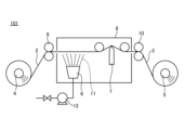
- FIG. 1 is a schematic diagram of a peeling device according to an embodiment of the present invention.
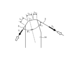
- FIG. 2 is a schematic diagram of a peeling member of a first embodiment of the peeling apparatus of the present invention. It is a schematic diagram of the peeling member of 2nd Embodiment in the peeling apparatus of this invention. It is a schematic diagram of the peeling member of 3rd Embodiment in the peeling apparatus of this invention.
- 2 is a graph showing the results of peeling off a film under the conditions of Example 1.
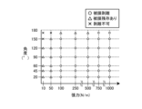
- 3 is a graph showing the results of peeling off a film under the conditions of Example 2.
- 3 is a graph showing the results of peeling off a film under the conditions of Example 3.
- the inventors of the present invention have conducted extensive research into a method for efficiently and reliably removing a coating from the surface of a coated film, which has a coating containing a water-soluble resin on one side of the base film, using a very small amount of cleaning liquid.
- the inventors have discovered the following film removal method and film removal apparatus.
- the method of peeling a film from a base film having a film according to the present invention targets a base film having a film containing a water-soluble resin on at least one side of the base film, and cleans the film and peels the film from the base film. This is how to remove it.
- the coating may be present on one side or both sides of the base film, and is not particularly limited.
- the target base film having a coating may be a base film having a coating containing a water-soluble resin in consideration of the environmental load, as well as a coating containing another water-soluble resin.
- the water-soluble resin includes at least one of water-soluble polyester resin, polyester urethane resin, acrylic resin, ethylene ionomer resin, polyvinyl alcohol resin, polyvinylpyrrolidone resin, ethylene-vinyl alcohol resin, and starch. It is more preferable to use seeds as a main component.
- a film containing a water-soluble resin may be a single layer containing a water-soluble resin or a laminate of two or more layers containing a water-soluble resin. It may also be a laminate of layers that do not contain such a material.
- a release film with a coating containing a release component in addition to the water-soluble resin in a part of the coating is particularly preferred, and can efficiently exhibit the effect of peeling off the coating.
- the release component referred to here is a component that increases the contact angle of the film surface with water, that is, reduces the surface energy of the film.
- Type silicone resin compounds, UV-curable silicone resin compounds in which a photopolymerization initiator is blended with an organopolysiloxane containing an acryloyl or methacryloyl group and cured by irradiation with UV light, and other types have long-chain alkyl groups. Compounds and compounds containing fluorine can be mentioned.
- the coating may be a mixture of a water-soluble resin and a release component, or may be a stack of layers of each.
- a layer containing a water-soluble resin is formed directly above the base film, and then a layer containing a mold release component is formed on the outermost surface, and the mold release component has water permeability.
- the coating peeling method of the present invention includes applying a cleaning liquid containing water as a main component to the coating surface of a base film having a coating containing the above-mentioned water-soluble resin on at least one side in an amount of 3 to 650 ml per 1 m 2 of surface area of the coating. Then, the peeling member is brought into contact with the surface of the coating to which the cleaning liquid has been applied, and the angle formed by the base film through the peeling member is in the range of 20 to 150°, and at least one direction in the longitudinal direction of the base film is applied.
- a film peeling method in which a film is removed from a base film having a film by moving the base film relative to a peeling member in its longitudinal direction while applying a tension in the range of 10 to 1000 N/m. be.
- the method for applying the cleaning liquid to the coating surface in the coating removal method of the present invention may be any method.
- the cleaning liquid may be applied in the form of droplets using a spray nozzle, or the cleaning liquid may be applied in the form of droplets using a high-pressure washer or a steam generator.
- a high-pressure or high-temperature cleaning solution may be applied using a high-pressure or high-temperature cleaning solution.
- the amount of the cleaning liquid applied is preferably adjusted as appropriate depending on the properties and thickness of the film to be peeled off, and is preferably appropriately controlled by the method of applying the cleaning liquid.
- the cleaning solution may be managed by pumping it with a metering pump, a flow meter may be installed in the middle of the flow path where the cleaning solution is sent, or the cleaning solution applied to the coating surface may be collected and its mass measured. Good too.
- the water-soluble resin contains cleaning liquid and it is difficult to measure the mass, collect the base film with the coating, the applied cleaning liquid, and the peeled coating, and calculate the amount of cleaning liquid applied. It may be calculated.
- the amount of cleaning liquid applied should be 3 ml or more per 1 m 2 of surface area of the coating. It was confirmed that the effect of peeling off the film could be obtained. It has been confirmed that if the amount of water is less than 3 ml per 1 m2 of surface area of the coating, the effectiveness of coating removal may be reduced, especially when the humidity of the surrounding environment is low. The drying of the cleaning liquid may proceed before it is swollen, and the effect of peeling the film may not be obtained.
- the larger the amount of cleaning liquid applied the more reliably the coating containing the water-soluble resin can be dissolved or swollen, and the more effectively the coating is peeled off.
- the effect of peeling the coating can be obtained by applying 650 ml of cleaning liquid to the coating surface per 1 m 2 of surface area of the coating.
- the cleaning liquid used in the film removal method of the present invention can be effective in any solvent as long as it can dissolve the water-soluble resin, but in order to reduce the environmental burden, it is preferable to use water. Furthermore, by adding a surfactant or the like to a water-based composition, the wettability between the cleaning liquid and the coating surface may be improved, and the cleaning liquid may be easily spread over the entire coating.
- Examples of the peeling member in the film peeling method of the present invention include, but are not limited to, a scraper, a cloth, a metal plate, a rotating brush roll, etc., and the peeling member directly contacts the base film having the film, Any means may be used as long as the coating can be physically peeled off. Further, it is preferable that the peeling member be brought into direct contact with the coated surface of the base film by pressing the peeling member, and the base film is maintained in a bent or curved state by the peeling member. The film can be peeled off from the base film by moving the base film relative to the peeling member in the longitudinal direction while keeping the base film in place.
- the above-mentioned bent or curved base film has an angle formed by the base film in the range of 20 to 150° through the peeling member, and tension is applied in at least one longitudinal direction in the range of 10 to 1000 N/m. It is preferable that the peeling member can be strongly pressed against the coating surface of the base film, so that the coating dissolved or swollen by the cleaning liquid can be efficiently and reliably peeled off. Therefore, the narrower the area in which the peeling member contacts the base film having the coating, the more strongly the peeling member can be locally pressed against the coated surface of the base film, which is preferable.
- a scraper, a corner of a metal plate, etc. are preferably used.
- the angle formed by the base film through the peeling member is less than 20°, it is not practical because the space in which the peeling member is installed becomes very narrow.
- the angle is made larger than 150°, the force pressing the release member against the coating surface of the base film will be weaker, but it may still be possible to peel off some coatings that have easy-to-peel properties. It could be confirmed.
- tension fluctuations occur when the base film and the release member are moved relative to each other in the longitudinal direction of the base film, or if the peel speed is increased, there may be a gap between the base film and the release member. It has been confirmed that air is easily entrained, and a part of the film may not be peeled off, but may slip through and remain on the base film.
- the film peeling effect was achieved when the tension applied in at least one longitudinal direction of the base film was 10 N/m or more.
- the base film is conveyed with an applied tension of less than 10 N/m, stable conveyance is not possible due to the low tension, and the tension fluctuates greatly and meandering occurs during conveyance. It may become impossible to peel off the coating.
- a tension exceeding 1000 N/m is applied, the base film is strongly pulled in one direction, resulting in multiple corrugated iron wrinkles occurring in the width direction of the base film in the longitudinal direction. Some corrugated iron wrinkles form creases at locations where they come into contact with the peeling member, and the film may not be able to be peeled off at the creases.
- the film is peeled from the base film having the film by moving the base film having the film in the preferred form described above relative to the peeling member in its longitudinal direction.
- Any means may be used to move the base film relative to the peeling member; the peeling member may be fixed and only the base film may be transported, or the base film may be moved relative to the stationary base film.
- the peeling member may be moved.
- both the peeling member and the base film may be moving, and both may be moving in the same direction or in different directions.
- the target base film has a coating that is continuous or discontinuous in the longitudinal direction of the base film
- the base film is conveyed and the peeling member is attached to the base film. It is preferable to peel off the film while the film is in a state where it extends and is fixed in the lateral direction.
- the base film that has a coating may have a coating intermittently in the longitudinal direction of the base film, or the amount of coating formed on the base film may vary along the longitudinal direction of the base film.
- the transport speed of the base film variable, the time for the coating to dissolve or swell with the cleaning liquid can be changed, or the time for contact between the area with the coating and the peeling member can be changed.
- the time for the coating to dissolve or swell is preferably determined appropriately depending on the properties of the coating, but in consideration of the device size, etc., it is 0.05 ⁇ It is preferable to set the time to 10 seconds.
- the conveyance may be stopped or the conveyance may be stopped.
- the film may be peeled off by changing the speed and moving the peeling member relative to the part of the base film that has the film, and after the film is peeled off, the conveyance is started again.
- it is possible to remove the coating with high efficiency and reliability by adjusting the transfer speed or returning the conveyance speed to the original speed.
- the above inspection method may be any method as long as it can detect the remaining coating.
- the contact length in the longitudinal direction of the base film is L, and the center position of the contact length is L.
- a vertical plane perpendicular to the surface of the release member, the side where the base film approaches the release member relatively is the upstream side, and the side where the base film moves away from the release member relative to the release member.
- the contact length L [m] is in the range of 1 ⁇ 10 -5 to 1 ⁇ 10 -3 m, and the angle ( acute angle) ⁇ 1 [°], the angle (acute angle) ⁇ 2 [°] between the vertical plane and the base film located downstream of the vertical plane, the base material located upstream of the vertical plane
- the tension T 1 [N/m] applied to the film and the tension T 2 [N/m] applied to the base film on the downstream side of the vertical plane are expressed by the following formula (1). It is preferable to peel off the coating as follows.
- the contact length L is 5 ⁇ 10 ⁇ 6 m at the shortest. This was the limit of machining. Even if you try to process it to less than 5 x 10 -6 m, burrs will appear during processing , and even if you remove the generated burrs with abrasive paper or abrasive cloth, polishing marks will remain. It was not possible to produce it.
- the tension T 1 and T 2 are set large in order to satisfy the above formula (1), and the tension between the vertical surface and the base film is further increased. It is necessary to keep the angles ⁇ 1 and ⁇ 2 as small as possible. In this case, even if you try to adjust the peeling conditions of the film according to the properties of the film to be peeled off, the range that can be adjusted in the above formula (1) will be narrowed, so the properties that are relatively easy to peel off will be narrowed. It was possible to remove the film only from the following films.
- the coating peeling method of the present invention when a rigid body such as a scraper or a metal plate with a tip shape as shown in FIG. Of the two surfaces including the ridge line where the peeling begins, the surface facing the base film before contacting the ridge line (hereinafter sometimes referred to as the upstream side r1 of the peeling member) and the surface before contacting the ridge line It is preferable to peel off the film while setting the angle ⁇ 3 between the film and the base film to be 5° or more. When the angle is less than 5°, the peeled film (hereinafter referred to as peeled material) is formed between the base film that approaches the peeling member relatively and the upstream side surface r1 of the peeling member. ) was confirmed to accumulate.
- peeled material peeled material
- the coating When the coating is continuously peeled off, a part of the deposited peeled material overflows to the edge of the base film in the width direction, and the side surface of the edge of the base film in the width direction is spilled out. In rare cases, it adhered to the back side of the base film. On the other hand, it was confirmed that by setting the angle ⁇ 3 to 5° or more, the amount of deposited peeling material was significantly reduced. When the angle is 5° or more, the peeled material does not flow along the upstream side surface r1 of the peeling member and overflow in the transverse direction of the base film, and can be stably and continuously. The film could be peeled off.
- FIG. 1 is a schematic diagram of a film stripping device 101 according to an embodiment of the present invention.
- the film peeling device 101 includes an unwinding device 4 that unwinds a base film 2 having a film, and a winding device 5 that winds up the base film 3 after the film has been peeled off.
- a film peeling device 101 includes a drive device 9 for conveying a base film 2 having a film between an unwinding device 4 and a winding device 5, and a cleaning liquid 11 for applying a cleaning liquid 11 to the film of the base film 2 having a film.
- a discharge head 6 as a cleaning liquid applying mechanism for cleaning
- a peeling member 7 for peeling off both the coating of the base film 2 having a coating and the cleaning liquid 11, and a drive for transporting the base film 3 after the coating has been peeled off.
- a device 10 is provided.
- the cleaning liquid application mechanism also includes a liquid feeding pump 12 for feeding the cleaning liquid 11 to the ejection head 6, and a tank (not shown) for storing the cleaning liquid.
- the base film is transported by the drive devices 9 and 10, and the base film moves with respect to the peeling member 7 in its longitudinal direction. Further, it is preferable that the drive devices 9 and 10 have a structure that can cut tension in order to stably transport the base film. When tension cutting is performed using a suction roll, a part of the coating on the base film 2 that has a coating may be sucked, which may cause trouble. configuration is more preferably used.
- the drives 9, 10 also function as tensioning mechanisms.
- the rotational speed of each of the drive rolls of the drive devices 9 and 10 can be set individually, and by controlling the rotation speed, the rotation speed of the drive rolls of each of the drive devices 9 and 10 can be set, and by controlling the rotation speed, It is preferable to include a mechanism (tension control mechanism) that can control the tension applied in the longitudinal direction of the film.
- the invention is not limited to this, as long as it has a mechanism that can control the tension applied to the base film in the longitudinal direction of the base film.
- a tension meter (not shown) is installed between the drive device 9 and the peeling member 7, or between the peeling member 7 and the drive device 10, or both, so that a predetermined tension is achieved.
- a peeling member is provided so that the coating can be peeled off at a constant speed even when the base film 2 having the coating is intermittently conveyed in order to deal with troubles during operation that occur in step 101 or for inspection before peeling off the coating.
- An accumulator (not shown) may be provided closer to the unwinding device 4 than 7.
- a dancer roll (not shown) may be provided between the drive device 9 and the drive device 10 to reduce tension fluctuations that occur when changing the conveyance speed, but it is possible to Any means that can reduce fluctuations are not limited to these.
- the base film moves in the longitudinal direction with respect to the peeling member 7.
- the mechanism may be provided with a mechanism for moving the peeling member 7 relative to the stationary base film, or it may be a mechanism for moving both the peeling member 7 and the base film, both in the same direction or in different directions. It may also be a mechanism that moves.
- the ejection head 6 and the peeling member 7, which are part of the cleaning liquid application mechanism, are surrounded by a booth 8.
- the ejection head 6 only needs to be able to eject the cleaning liquid 11 and apply it to the coating surface of the base film 2 having a coating, and examples thereof include a slit nozzle and a spray nozzle, but the invention is not limited thereto.
- the amount of cleaning liquid 11 applied to the coating surface of the base film 2 having a coating is preferably in the range of 3 to 650 ml/m 2 so as to sufficiently dissolve the coating containing the water-soluble resin.
- the amount of cleaning liquid 11 applied may be controlled by using a metering pump as the liquid pump 12, or by installing a flow meter (not shown) between the liquid feeding pump 12 and the discharge nozzle 6, and controlling the amount of the cleaning liquid 11. Control may be performed by feeding back the instruction value. Alternatively, the discharged cleaning liquid 11 may be collected, the amount of application may be determined from its mass, and the amount of application may be controlled by feeding back to the liquid feeding pump.
- the ejection head 6 and the peeling device 7 may be installed facing the coating surface of the base film 2 having a coating.
- the coating is laminated on the bottom side of the base film 2
- the discharge head 6 and the peeling device 7 are installed so as to face the bottom side of the base film 2 on which the coating is laminated.
- the installation is not limited to the lower surface side of the film 2.
- the unwinding direction of the base film 2 having a coating is changed so that the coating of the base film 2 wound into a roll can be applied to either the inside or outside of the roll. It is more preferable that the unwinding device has a mechanism that can handle both upward and downward feeding so that the coating surface of the base film 2 can be conveyed facing the ejection head 6 and the peeling device 7.
- the ejection head 6 is preferably capable of ejecting the heated cleaning liquid 11 in order to quickly dissolve the water-soluble resin contained in the coating.
- the cleaning liquid 11 may be heated by providing the ejection head 6 with a heat source such as a cartridge heater, or by heating a tank (not shown) storing the cleaning liquid, but any means that can heat the cleaning liquid 11 may be used. However, it is not limited to these.
- the cleaning liquid 11 may be ejected from the ejection head 6 in the form of steam.
- the material of the ejection head 6 is preferably heat resistant in order to eject the heated cleaning liquid 11, and metal or heat resistant resin is preferably used.
- FIG. 2 is a schematic cross-sectional view of the peeling member 7 of the first embodiment in the film peeling apparatus 101.
- the peeling member 7 directly contacts the coating surface of the base film 2 having a coating, and the angle formed by the base film through the peeling member 7, that is, the base film 3 from which the coating has been peeled and the base film before the coating is peeled. 2 and the angle ( ⁇ 1 + ⁇ 2 ) is in the range of 20 to 150°.
- the peeling member 7 bends or vibrates when peeling the coating from the base film 2, or when the tension applied to the base film 2 is high. may be deformed or damaged, causing problems in peeling off the coating.
- the force with which the peeling member 7 is pressed against the base film 2 becomes weaker.
- the force with which the peeling member 7 is pressed against the base film 2 becomes weaker.
- the force that presses the peeling member 7 against the base film 2 increases. If the amount is insufficient, the coating may not be peeled off and a portion of the coating may remain on the base film.
- the tension in the longitudinal direction of the base film (T 1 , T 2 ) applied to the base film is controlled by the aforementioned tension control mechanism, and the tension can be adjusted in the range of 10 to 1000 N/m. preferable.
- the applied tension and the angle formed by the base film through the peeling member 7 may be adjusted depending on the properties of the base film 2 having the film to be peeled off. The smaller the angle, the more strongly the base film 2 having the coating can be pressed against the peeling member 7, and therefore the coating can be peeled off more reliably. However, if the pressing force is too strong, it may exceed the breaking strength of the base film and the base film may break.
- the inventors found that by setting the tension to 1000 N/m or less, even when the angle formed by the base film was made small, the film could be continuously formed without breaking the base film. It was confirmed that peeling could be performed. If the tension exceeds 1000 N/m, the base film may occasionally break due to foreign matter attached to the tip of the peeling member 7 or slight burrs generated during processing when manufacturing the peeling member 7. I also checked the situation. On the other hand, the lower the tension, the smaller the force with which the peeling member 7 is pressed against the base film, making it more difficult to peel off the film.
- the lower limit of the tension is preferably 50 N/m or more, more preferably 100 N/m or more.
- the peeling member 7 in the peeling device 101 of the present invention is provided so as to be in direct contact with the coating surface of the base film 2 having a coating. Adjust so that the angle ( ⁇ 1 + ⁇ 2 ) is in the range of 20 to 150°. In this state, it is preferable that the contact length L of the peeling member 7 in the longitudinal direction of the base film in the range in which it contacts the coating surface is in the range of 1 ⁇ 10 ⁇ 5 to 1 ⁇ 10 ⁇ 3 m. At this time, in order to strengthen the force of pressing the peeling member 7 against the base film, the shorter the contact length L, the better.
- the limit of the contact length L that could be manufactured without causing warping or burrs during processing was 5 ⁇ 10 ⁇ 6 m.
- the contact length L is 5 ⁇ 10 ⁇ 6 m
- the tip of the peeling member 7 is It was sometimes deformed. Therefore, it has been found that in order to prevent the tip of the peeling member 7 from being deformed even under various conditions, it is more preferable that the contact length L is 1 ⁇ 10 ⁇ 5 m or more.
- the contact length L is long, the force for pressing the peeling member 7 against the base film is dispersed over a wide area by the contact length L, making it difficult to peel off the coating.
- the inventors found that by setting the contact length L to 1 ⁇ 10 -3 m or less, even if the properties of the target film change, the amount of cleaning liquid 11 applied and the amount applied to the base film can be adjusted. By adjusting the tension and the angle formed between the base films via the peeling member 7, the film could be peeled off. If the contact length L exceeds 1 ⁇ 10 ⁇ 3 m, the force for pressing the peeling member 7 against the base film is dispersed and becomes smaller, making it difficult to peel the film stably. Some film remained.
- FIG. 3 is a schematic diagram of the second peeling member 13 in the film peeling apparatus 101 of the present invention.
- the contact length L in the longitudinal direction of the base film in the range that contacts the coating surface of the peeling member 13 includes the case where the tip of the peeling member 13 is an arc.
- FIG. 4 is a schematic diagram of the third peeling member 14 in the film peeling apparatus 101 of the present invention.
- the contact length L corresponds to the sum of L 1 , L 2 , and L 3 .
- the sum of the contact lengths L 1 , L 2 , and L 3 is preferably in the range of 1 ⁇ 10 ⁇ 5 to 1 ⁇ 10 ⁇ 3 m.
- the booth 8 of the stripping device 101 is designed to prevent the cleaning liquid 11 from scattering around, and to prevent the temperature of the cleaning liquid 11 from decreasing when the cleaning liquid 11 is heated. It is provided so as to surround up to the peeling device 7.
- the material of the booth 8 is preferably heat resistant because the inside of the booth 8 becomes high temperature, and metal, glass, or the like is preferably used.
- a drying device may be provided between the two.
- the drying device may be provided before winding up, and may be provided either before or after the drive device 10.
- an inspection machine (not shown) may be installed in front of the winding device 5 to detect coating residue and environmental foreign matter attached during the process. good.
- the inspection device may be selected according to the properties of the base film 3, and an inspection device using transmitted light or reflected light is preferably used.
- a marking device (not shown) may be provided between the inspection device and the winding device 5 for recording the position of the coating residue detected by the inspection device or the environmental foreign matter attached during the process.
- the marking method by the marking device may be any method, such as a pen, a sticker, or a laser, as long as the position of the detection target can be marked.
- the base film having a coating may be in the form of cut sheets, but it is particularly preferably a base film having a coating wound into a roll.
- a base film having a film wound into a roll By unwinding a base film having a film wound into a roll, peeling the film using the film peeling device of the present invention, and winding up the base film after the film has been peeled off, the film can be continuously and efficiently processed. It is possible to perform coating removal treatment.
- the substrate film 2 having the coating is disposed between the unwinding device 4 and the drive device 9.
- a device may be provided to expose the layer containing a large amount of water-soluble resin in the coating.
- the coating of the base film having a coating is a thermosetting silicone resin compound having dimethylsiloxane as its main skeleton
- the base film having the coating is suitable as a mold release film for processes due to its surface free energy characteristics. Specifically, it is used as a release film for providing a release object on the coating of a base film having a coating and then extracting the release object in a desired shape.
- the base film having the coating may have a release material remaining on the surface of the coating, so the unwinding device 4 and the drive device 9 It is preferable that a device for exposing the coating surface of the base film having the coating is provided between the two and exposing the coating surface of the base film having the coating.
- the device for exposing the coating surface may be a contact type or a non-contact type, and is appropriately selected depending on the remaining state of the object to be released.
- the material to be released is selected as appropriate depending on the characteristics of the film, but main materials include inorganic materials such as metals provided by vapor deposition, adhesives made of organic materials such as acrylic materials provided by coating, and barium titanate.
- inorganic materials such as metals provided by vapor deposition
- adhesives made of organic materials such as acrylic materials provided by coating
- barium titanate An example is a ceramic green sheet as a component.
- the water-soluble resin can be dissolved from the surface of a film having a film using a small amount of cleaning liquid, and the film can be efficiently and reliably peeled off. be able to.
- high purity resin chips free of foreign matter can be obtained at low cost without significantly increasing the environmental load, so the recycled film can be stabilized. It is possible to form a film by
- ⁇ Base film with coating> A coated film shown below was produced.
- ⁇ Film with coating> A film of polyvinyl alcohol resin as a water-soluble resin was formed to a thickness of 0.1 ⁇ m on one side of a base film of polyethylene terephthalate having a thickness of 30 ⁇ m and a width of 100 mm.
- a film of a curable silicone resin as a release component was formed thereon to a thickness of 0.1 ⁇ m as follows, with reference to the coating material described in JP-A-2015-189226.
- ⁇ Thermosetting silicone manufactured by Shin-Etsu Chemical Co., Ltd., trade name "KS-847T”: 100 parts by mass
- ⁇ Platinum catalyst manufactured by Shin-Etsu Chemical Co., Ltd., trade name "CAT-PL-50T”: 3 parts by mass
- KS-847T 100 parts by mass
- CAT-PL-50T 3 parts by mass
- it was applied onto the polyvinyl alcohol resin film using a bar coater and dried in an oven at 90° C. for 20 seconds to form a release component film, thereby obtaining a film with a film.
- Peelability of coating Peeling was evaluated using a commercially available dyne pen (surface energy: 30, 70 mN/m) in the following manner. When drawing with a dyne pen on the surface of a sample under a room temperature of 23° C. and maintaining that state for 4 seconds or more, it was determined that the surface energy of the sample surface was higher than the surface energy of the dyne pen. If the film of the release component of the coated film remains on the surface, the surface energy of both of these is less than 30 mN/m, so the reagent of any dyne pen will be repelled by the sample surface and the drawing will not be maintained.
- the surface energy is 70 mN/m or more, so any dyne pen can maintain drawing.
- the surface energy is 43.8 mN/m, so the dyne pen of 30 mN/m The drawing is maintained, but the drawing of the 70 mN/m dyne pen cannot be maintained.
- the mold release component of the membrane-coated film If the coating of the mold release component of the membrane-coated film remains on the surface, the mold release component will mix into the recycled resin chips, causing the recycled resin chips to become colored (yellowing) and generate foreign matter. The quality of the chip deteriorates and it becomes unusable. Although the film of the mold release component has been peeled off, if some of the water-soluble polyvinyl alcohol resin film remains, the recycled resin chip will be slightly colored (yellowing) and the quality will be poor compared to the quality of the raw material. Although it is slightly inferior, it is within the practical range. If both the release component coating and the water-soluble polyvinyl alcohol resin coating are peeled off, the recycled resin chip will have good quality.
- Example 1 The coated film was set in the unwinding device 4 of the peeling device 101 shown in FIG. A spray nozzle (two-fluid system) was used for the discharge head 6 that discharges the cleaning liquid 11.
- the cleaning solution was hot water at 60° C., and the discharge amount was adjusted to 3 to 650 ml per 1 m 2 of surface area of the coating using a diaphragm pump, and the solution was directly applied to the coating.
- the peeling member 7 was a stainless steel plate with a tip shaped as shown in FIG. 2, and the width of the tip in the substrate transport direction was 1.0 ⁇ 10 ⁇ 5 m.
- the peeling member 7 was arranged so that the angle ( ⁇ 1 + ⁇ 2 ) between the base films through the peeling member 7 was 90° ( ⁇ 1 : 45°, ⁇ 2 : 45°). As a result, it was confirmed that the length L where the base film and the tip of the plate directly contact each other in the transport direction was 1.0 ⁇ 10 ⁇ 5 m.
- the ejection head 6 and the peeling member 7 were arranged so that the base film reached the peeling member 7 one second after being applied with hot water by the ejection head 6.
- the film was peeled off by conveying the base film while applying a tension of 10 N/m from both directions in the longitudinal direction of the base film. Furthermore, in the same apparatus configuration, the coating was peeled at tensions of 500 N/m and 1000 N/m.
- the base film 3 was taken up with the winding device 5 and the film was peeled off, and the state of peeling of the film was confirmed using a dyne pen. It was confirmed that when the amount was adjusted to a range of 650 ml/m 2 , both the coatings of the curable silicone resin as the release component and the water-soluble polyvinyl alcohol resin could be peeled off. Under the condition of a tension of 500 N/m, if the amount of water applied was adjusted to a range of 10 to 650 ml/m 2 , both the curable silicone resin and water-soluble polyvinyl alcohol resin coatings of the release component could be peeled off. .
- Example 2 The coated film was set in the unwinding device 4 of the peeling device 101 shown in FIG.
- the amount of water applied to the film was 100 ml/m 2 .
- the angle ( ⁇ 1 + ⁇ 2 ) formed by the base film via the peeling member 7 was 20°, and the tension was 500 N/m.
- the film was otherwise peeled off in the same manner as in Example 1. Also, using the same device components, it was modified so that the angle ( ⁇ 1 + ⁇ 2 ) could be changed, and the angle ( ⁇ 1 + ⁇ 2 ) was changed to 45° ( ⁇ 1 : 22.5°, ⁇ 2 : 22.5°).
- FIG. 6 shows whether or not the film can be coated at each level.
- " ⁇ ” in the figure indicates conditions under which it was confirmed that both the curable silicone resin and water-soluble polyvinyl alcohol resin coatings of the mold release component could be peeled off.
- " ⁇ ” in the figure indicates a condition in which the curable silicone resin was peeled off, but a portion of the polyvinyl alcohol resin remained on the surface of the base film.
- the "x" in the figure indicates a condition in which both the curable silicone resin and the polyvinyl alcohol resin partially remained on the surface of the base film. From this result, it was confirmed that the more obtuse the angle between the film-releasable base films and the lower the applied tension, the more the film remained unremoved.
- Example 3 The coated film was set in the unwinding device 4 of the peeling device 101 shown in FIG.
- a plurality of types of stainless steel plates having tip shapes as shown in FIG. 2 were prepared for the peeling member 7, and the length L at which the tip portion directly contacted the base film in the transport direction was changed.
- L is 1.0 ⁇ 10 ⁇ 5 , 2.5 ⁇ 10 ⁇ 5 , 5.0 ⁇ 10 ⁇ 5 , 1.0 ⁇ 10 ⁇ 4 , 2.0 ⁇ 10 ⁇ 4 , 5.0 ⁇ 10 -4 m , 7.5 ⁇ 10 ⁇ 4 m , and 1.0 ⁇ 10 ⁇ 3 m, each plate was prepared.
- the angle ( ⁇ 1 + ⁇ 2 ) formed by the base film through the peeling member 7 was varied in the range of 20° to 150°, and the tension was also varied in the range of 10 to 1000 N/m.
- the distance between the ejection head 6 and the peeling member 7 was adjusted each time so that hot water reached the peeling member 7 one second after being applied to the base film. In other respects, the coating was peeled off in the same manner as in Example 1.
- FIG. 7 shows the correlation between coating availability and ⁇ T 1 ⁇ cos( ⁇ 1 )+T 2 ⁇ cos( ⁇ 2 ) ⁇ /L at each level. Note that the meanings of each symbol in the figure are the same as in the second embodiment.
- formula (1) 1.0 ⁇ 10 6 ⁇ T 1 ⁇ cos( ⁇ 1 )+T 2 ⁇ cos( ⁇ 2 ) ⁇ /L ⁇ 2.4 ⁇ 10 8 It was confirmed that the film could be peeled off.
- ⁇ Comparative example 1> The coated film was set in the unwinding device 4 of the peeling device 101 shown in FIG. The coating was peeled off in the same manner as in Example 1, except that the discharge amount of the cleaning liquid 11 was adjusted to 2 ml per 1 m 2 of surface area of the coating.
- the base film 3 was taken up by the take-up device 5 and the coating was peeled off, and the peeling state of the coating was confirmed using a dyne pen, it was found that the releasing component, curable silicone resin, and water-soluble polyvinyl alcohol resin were mixed. It was confirmed that the coating remained in all cases. Since it was confirmed that both films remained, no further evaluation was conducted.
- ⁇ Comparative example 2> The coated film was set in the unwinding device 4 of the peeling device 101 shown in FIG. A tension of 1100 N/m was applied from both directions in the longitudinal direction of the base film. Other than that, the coating was peeled off in the same manner as in Example 1. Due to the application of high tension, corrugated iron-like wrinkles were generated in the base film in the direction of conveyance. Since the generated wrinkles passed through the peeling member 7 as they were, it was visually confirmed that the film remained at the same position in the width direction of the film as the wrinkles occurred. The base film 3 from which the film had been peeled off after being wound up by the winding device 5 was taken and the state of peeling of the film was confirmed using a dyne pen.
- both the curable silicone resin and water-soluble polyvinyl alcohol resin coatings remained.
- both the curable silicone resin and water-soluble polyvinyl alcohol resin coatings of the release component could be peeled off at positions where wrinkles were not generated. Since it was difficult to extract from the collected base film 3 only the areas where any film was peeled off, no further evaluation was carried out.
- the base film having a film that can be applied to the method and device for peeling a film from a base film having a film of the present invention is not limited to a film having a film containing a water-soluble resin on one side of the base film; Any recyclable resin film, paper film, or metal film having a coating including a soluble resin layer may be used.
Landscapes
- Engineering & Computer Science (AREA)
- Chemical & Material Sciences (AREA)
- Polymers & Plastics (AREA)
- Health & Medical Sciences (AREA)
- Chemical Kinetics & Catalysis (AREA)
- Medicinal Chemistry (AREA)
- Life Sciences & Earth Sciences (AREA)
- Organic Chemistry (AREA)
- Sustainable Development (AREA)
- Environmental & Geological Engineering (AREA)
- Mechanical Engineering (AREA)
- Manufacturing & Machinery (AREA)
- Application Of Or Painting With Fluid Materials (AREA)
- Separation, Recovery Or Treatment Of Waste Materials Containing Plastics (AREA)
Priority Applications (3)
| Application Number | Priority Date | Filing Date | Title |
|---|---|---|---|
| CN202380029239.9A CN118946445A (zh) | 2022-05-10 | 2023-04-05 | 被膜剥离方法及被膜剥离装置 |
| JP2023522766A JPWO2023218811A1 (https=) | 2022-05-10 | 2023-04-05 | |
| KR1020247033352A KR20250008038A (ko) | 2022-05-10 | 2023-04-05 | 피막 박리 방법 및 피막 박리 장치 |
Applications Claiming Priority (2)
| Application Number | Priority Date | Filing Date | Title |
|---|---|---|---|
| JP2022-077329 | 2022-05-10 | ||
| JP2022077329 | 2022-05-10 |
Publications (1)
| Publication Number | Publication Date |
|---|---|
| WO2023218811A1 true WO2023218811A1 (ja) | 2023-11-16 |
Family
ID=88730082
Family Applications (1)
| Application Number | Title | Priority Date | Filing Date |
|---|---|---|---|
| PCT/JP2023/014111 Ceased WO2023218811A1 (ja) | 2022-05-10 | 2023-04-05 | 被膜剥離方法および被膜剥離装置 |
Country Status (5)
| Country | Link |
|---|---|
| JP (1) | JPWO2023218811A1 (https=) |
| KR (1) | KR20250008038A (https=) |
| CN (1) | CN118946445A (https=) |
| TW (1) | TW202345979A (https=) |
| WO (1) | WO2023218811A1 (https=) |
Citations (3)
| Publication number | Priority date | Publication date | Assignee | Title |
|---|---|---|---|---|
| JP2001179741A (ja) * | 1999-12-28 | 2001-07-03 | N Tsuu Syst Kk | シート上の塗布物の剥離方法及び剥離装置 |
| JP2001259538A (ja) * | 2000-03-21 | 2001-09-25 | Chuki Seiki Kk | フィルムから付着物を除去する方法及びその装置 |
| JP2004169005A (ja) * | 2002-11-05 | 2004-06-17 | Toray Ind Inc | 積層フィルムのリサイクル方法およびリサイクル製品 |
Family Cites Families (2)
| Publication number | Priority date | Publication date | Assignee | Title |
|---|---|---|---|---|
| JP2004363140A (ja) | 2003-06-02 | 2004-12-24 | Toray Ind Inc | 積層フィルムの剥離方法および剥離装置 |
| JP7460069B2 (ja) | 2020-03-23 | 2024-04-02 | 株式会社ユニチカテクノス | ポリ塩化ビニリデンコーティングフィルムからの熱可塑性樹脂フィルムの回収方法及び回収装置 |
-
2023
- 2023-04-05 CN CN202380029239.9A patent/CN118946445A/zh active Pending
- 2023-04-05 JP JP2023522766A patent/JPWO2023218811A1/ja active Pending
- 2023-04-05 KR KR1020247033352A patent/KR20250008038A/ko active Pending
- 2023-04-05 WO PCT/JP2023/014111 patent/WO2023218811A1/ja not_active Ceased
- 2023-04-28 TW TW112115940A patent/TW202345979A/zh unknown
Patent Citations (3)
| Publication number | Priority date | Publication date | Assignee | Title |
|---|---|---|---|---|
| JP2001179741A (ja) * | 1999-12-28 | 2001-07-03 | N Tsuu Syst Kk | シート上の塗布物の剥離方法及び剥離装置 |
| JP2001259538A (ja) * | 2000-03-21 | 2001-09-25 | Chuki Seiki Kk | フィルムから付着物を除去する方法及びその装置 |
| JP2004169005A (ja) * | 2002-11-05 | 2004-06-17 | Toray Ind Inc | 積層フィルムのリサイクル方法およびリサイクル製品 |
Also Published As
| Publication number | Publication date |
|---|---|
| CN118946445A (zh) | 2024-11-12 |
| JPWO2023218811A1 (https=) | 2023-11-16 |
| KR20250008038A (ko) | 2025-01-14 |
| TW202345979A (zh) | 2023-12-01 |
Similar Documents
| Publication | Publication Date | Title |
|---|---|---|
| EP4306223A1 (en) | Method for separating coating from film with coating, and apparatus for separating coating | |
| CN108856024B (zh) | 用于从膜移除油墨的方法和系统 | |
| JP2004169005A (ja) | 積層フィルムのリサイクル方法およびリサイクル製品 | |
| CN114791645A (zh) | 光学膜的制造方法 | |
| WO2024058133A1 (ja) | コーティング層の除去方法及びコーティング層の除去装置 | |
| JP2025001739A (ja) | 被膜除去装置および被膜除去方法 | |
| JP2010179276A (ja) | フィルム表面の異物除去装置及びフィルムの製造方法 | |
| WO2023218811A1 (ja) | 被膜剥離方法および被膜剥離装置 | |
| WO2006014009A1 (en) | Producing method for film | |
| TW202337572A (zh) | 從附有被膜的薄膜剝離被膜之方法及剝離被膜之裝置 | |
| JP7826784B2 (ja) | 被膜剥離装置および被膜剥離方法 | |
| CN120460237A (zh) | 涂布设备的运动元件的清洁系统、相关的涂布机、涂布设备和方法 | |
| JP2011056839A (ja) | 除去版洗浄方法、除去版洗浄用基板、インキの回収方法、インキの再生方法、及び除去版洗浄装置 | |
| TW202513255A (zh) | 被膜剝離裝置及被膜剝離方法 | |
| TW202348386A (zh) | 被膜剝離裝置及被膜剝離方法 | |
| TWI913410B (zh) | 從附有被膜之薄膜的被膜剝離方法及被膜剝離裝置 | |
| EP4737023A1 (en) | Coating peeling device and coating peeling method | |
| JP7782301B2 (ja) | 被膜付きフィルムからの被膜の剥離装置 | |
| JP4403836B2 (ja) | ロール塗装方法および塗装装置 | |
| JP2024173758A (ja) | 被膜除去装置および被膜除去方法 | |
| CN118251295A (zh) | 从带被膜的膜剥离被膜的方法及被膜的剥离装置 | |
| JPWO2023218811A5 (https=) | ||
| JP2025004844A (ja) | 被膜剥離装置および被膜剥離方法 | |
| JPH11104547A (ja) | ウェブ塗布面のストリーク防止方法 | |
| JPH0416264A (ja) | カード類への塗布装置および方法 |
Legal Events
| Date | Code | Title | Description |
|---|---|---|---|
| ENP | Entry into the national phase |
Ref document number: 2023522766 Country of ref document: JP Kind code of ref document: A |
|
| 121 | Ep: the epo has been informed by wipo that ep was designated in this application |
Ref document number: 23803294 Country of ref document: EP Kind code of ref document: A1 |
|
| WWE | Wipo information: entry into national phase |
Ref document number: 202380029239.9 Country of ref document: CN |
|
| WWE | Wipo information: entry into national phase |
Ref document number: 12024552611 Country of ref document: PH Ref document number: 2401007198 Country of ref document: TH |
|
| WWE | Wipo information: entry into national phase |
Ref document number: 11202407457X Country of ref document: SG |
|
| NENP | Non-entry into the national phase |
Ref country code: DE |
|
| 122 | Ep: pct application non-entry in european phase |
Ref document number: 23803294 Country of ref document: EP Kind code of ref document: A1 |