WO2023218809A1 - 炭化珪素基板、炭化珪素エピタキシャル基板、炭化珪素基板の製造方法および炭化珪素半導体装置の製造方法 - Google Patents
炭化珪素基板、炭化珪素エピタキシャル基板、炭化珪素基板の製造方法および炭化珪素半導体装置の製造方法 Download PDFInfo
- Publication number
- WO2023218809A1 WO2023218809A1 PCT/JP2023/014085 JP2023014085W WO2023218809A1 WO 2023218809 A1 WO2023218809 A1 WO 2023218809A1 JP 2023014085 W JP2023014085 W JP 2023014085W WO 2023218809 A1 WO2023218809 A1 WO 2023218809A1
- Authority
- WO
- WIPO (PCT)
- Prior art keywords
- silicon carbide
- main surface
- pits
- less
- areal density
- Prior art date
- Legal status (The legal status is an assumption and is not a legal conclusion. Google has not performed a legal analysis and makes no representation as to the accuracy of the status listed.)
- Ceased
Links
Images










Classifications
-
- B—PERFORMING OPERATIONS; TRANSPORTING
- B24—GRINDING; POLISHING
- B24B—MACHINES, DEVICES, OR PROCESSES FOR GRINDING OR POLISHING; DRESSING OR CONDITIONING OF ABRADING SURFACES; FEEDING OF GRINDING, POLISHING, OR LAPPING AGENTS
- B24B37/00—Lapping machines or devices; Accessories
-
- B—PERFORMING OPERATIONS; TRANSPORTING
- B24—GRINDING; POLISHING
- B24B—MACHINES, DEVICES, OR PROCESSES FOR GRINDING OR POLISHING; DRESSING OR CONDITIONING OF ABRADING SURFACES; FEEDING OF GRINDING, POLISHING, OR LAPPING AGENTS
- B24B37/00—Lapping machines or devices; Accessories
- B24B37/04—Lapping machines or devices; Accessories designed for working plane surfaces
- B24B37/07—Lapping machines or devices; Accessories designed for working plane surfaces characterised by the movement of the work or lapping tool
- B24B37/08—Lapping machines or devices; Accessories designed for working plane surfaces characterised by the movement of the work or lapping tool for double side lapping
-
- C—CHEMISTRY; METALLURGY
- C30—CRYSTAL GROWTH
- C30B—SINGLE-CRYSTAL GROWTH; UNIDIRECTIONAL SOLIDIFICATION OF EUTECTIC MATERIAL OR UNIDIRECTIONAL DEMIXING OF EUTECTOID MATERIAL; REFINING BY ZONE-MELTING OF MATERIAL; PRODUCTION OF A HOMOGENEOUS POLYCRYSTALLINE MATERIAL WITH DEFINED STRUCTURE; SINGLE CRYSTALS OR HOMOGENEOUS POLYCRYSTALLINE MATERIAL WITH DEFINED STRUCTURE; AFTER-TREATMENT OF SINGLE CRYSTALS OR A HOMOGENEOUS POLYCRYSTALLINE MATERIAL WITH DEFINED STRUCTURE; APPARATUS THEREFOR
- C30B29/00—Single crystals or homogeneous polycrystalline material with defined structure characterised by the material or by their shape
- C30B29/10—Inorganic compounds or compositions
- C30B29/36—Carbides
-
- H—ELECTRICITY
- H10—SEMICONDUCTOR DEVICES; ELECTRIC SOLID-STATE DEVICES NOT OTHERWISE PROVIDED FOR
- H10P—GENERIC PROCESSES OR APPARATUS FOR THE MANUFACTURE OR TREATMENT OF DEVICES COVERED BY CLASS H10
- H10P52/00—Grinding, lapping or polishing of wafers, substrates or parts of devices
Definitions
- the present disclosure relates to a silicon carbide substrate, a silicon carbide epitaxial substrate, a method for manufacturing a silicon carbide substrate, and a method for manufacturing a silicon carbide semiconductor device.
- This application claims priority based on Japanese Patent Application No. 2022-078328, which is a Japanese patent application filed on May 11, 2022. All contents described in the Japanese patent application are incorporated herein by reference.
- Patent Document 1 describes a method for cleaning a silicon carbide substrate.
- a silicon carbide substrate according to the present disclosure includes a main surface.
- the silicon carbide substrate includes multiple carbon inclusions.
- a plurality of pits are formed on the main surface. When viewed in the direction perpendicular to the main surface, the maximum length of each of the plurality of carbon inclusions is 2 ⁇ m or more and 50 ⁇ m or less, and the area of each of the plurality of pits is 3000 ⁇ m 2 or more.
- the ratio of the areal density of the plurality of pits to the areal density of the plurality of carbon inclusions is 0.008 or less.
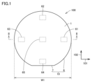
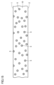
- FIG. 1 is a schematic plan view showing the configuration of a silicon carbide substrate according to this embodiment.
- FIG. 2 is a schematic cross-sectional view taken along line II-II in FIG.
- FIG. 3 is a schematic cross-sectional view showing the structure of carbon inclusions.
- FIG. 4 is a schematic plan view showing the configuration of the first pit.
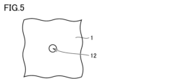
- FIG. 5 is a schematic plan view showing the configuration of the second pit.
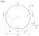
- FIG. 6 is a schematic plan view showing the structure of the silicon carbide epitaxial substrate according to this embodiment.
- FIG. 7 is a schematic cross-sectional view taken along line VII-VII in FIG. 6.
- FIG. 8 is a schematic plan view showing the configuration of the third pit.
- FIG. 9 is a schematic plan view showing the configuration of the fourth pit.
- FIG. 1 is a schematic plan view showing the configuration of a silicon carbide substrate according to this embodiment.
- FIG. 2 is a schematic cross-sectional view taken along line II-II in FIG.
- FIG. 3
- FIG. 10 is a schematic cross-sectional view showing a silicon carbide single crystal manufacturing apparatus according to this embodiment.
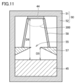
- FIG. 11 is a schematic cross-sectional view showing an example of the arrangement of silicon carbide raw materials arranged in the silicon carbide single crystal manufacturing apparatus according to the present embodiment.
- FIG. 12 is a flow diagram schematically showing a method for manufacturing a silicon carbide substrate according to this embodiment.
- FIG. 13 is a schematic cross-sectional view showing the structure of a silicon carbide base material.
- FIG. 14 is a schematic cross-sectional view showing the structure of the silicon carbide base material after the first chemical mechanical polishing step.
- FIG. 15 is a schematic cross-sectional view showing the structure of the silicon carbide base material after the cleaning step.
- FIG. 16 is a flowchart schematically showing a method for manufacturing a silicon carbide semiconductor device according to this embodiment.
- FIG. 17 is a schematic cross-sectional view showing the process of forming the body region.
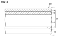
- FIG. 18 is a schematic cross-sectional view showing the process of forming a source region.
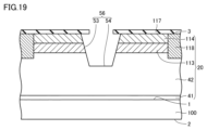
- FIG. 19 is a schematic cross-sectional view showing a step of forming a trench on the third main surface of the silicon carbide epitaxial layer.
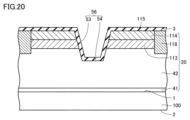
- FIG. 20 is a schematic cross-sectional view showing the process of forming a gate insulating film.
- FIG. 21 is a schematic cross-sectional view showing the process of forming a gate electrode and an interlayer insulating film.
- FIG. 22 is a schematic cross-sectional view showing the configuration of a silicon carbide semiconductor device according to this embodiment.
- An object of the present disclosure is to improve the yield of silicon carbide semiconductor devices. [Effects of this disclosure] According to the present disclosure, the yield of silicon carbide semiconductor devices can be improved. [Description of embodiments of the present disclosure] First, embodiments of the present disclosure will be listed and described.
- Silicon carbide substrate 100 includes main surface 1. Silicon carbide substrate 100 includes a plurality of carbon inclusions 5. A plurality of pits 11 are formed on the main surface 1. When viewed in the direction perpendicular to the main surface 1, the maximum length of each of the plurality of carbon inclusions 5 is 2 ⁇ m or more and 50 ⁇ m or less, and the area of each of the plurality of pits 11 is 3000 ⁇ m 2 or more. The ratio of the areal density of the plurality of pits 11 to the areal density of the plurality of carbon inclusions 5 is 0.008 or less.
- the ratio of the areal density of the plurality of pits 11 to the areal density of the plurality of carbon inclusions 5 may be 0.004 or less.
- the areal density of the plurality of carbon inclusions 5 may be 155 pieces/cm 2 or less.
- the areal density of the plurality of carbon inclusions 5 may be 100 pieces/cm 2 or less.
- the areal density of the plurality of carbon inclusions 5 may be 50 pieces/cm 2 or less.
- the maximum diameter of the main surface may be 150 mm or more.
- Silicon carbide epitaxial substrate 200 includes silicon carbide substrate 100 and silicon carbide epitaxial layer 20.
- Silicon carbide substrate 100 includes a plurality of carbon inclusions 5.
- Silicon carbide epitaxial layer 20 is provided on silicon carbide substrate 100.
- a plurality of pits 21 are formed on main surface 3 of silicon carbide epitaxial layer 20 . When viewed in the direction perpendicular to the main surface 3, the maximum length of each of the plurality of carbon inclusions 5 is 2 ⁇ m or more and 50 ⁇ m or less, and the area of each of the plurality of pits 21 is 5000 ⁇ m 2 or more.
- the ratio of the areal density of the plurality of pits 21 to the areal density of the plurality of carbon inclusions 5 is 0.01 or less.
- the ratio of the areal density of the pits 21 to the areal density of the plurality of carbon inclusions 5 may be 0.005 or less.
- the maximum diameter of main surface 3 may be 150 mm or more.
- a method for manufacturing a silicon carbide semiconductor device includes the following steps. Silicon carbide epitaxial substrate 200 according to any one of (7) to (9) above is prepared. Silicon carbide epitaxial substrate 200 is processed.
- a method for manufacturing silicon carbide substrate 100 according to the present disclosure includes the following steps. Chemical mechanical polishing is performed on silicon carbide base material 110 using the first polishing liquid. After chemical mechanical polishing is performed on silicon carbide base material 110, silicon carbide base material 110 is cleaned using a cleaning liquid. After silicon carbide base material 110 is cleaned using the cleaning liquid, chemical mechanical polishing is performed on silicon carbide base material 110 using the second polishing liquid. Silicon carbide base material 110 includes a plurality of carbon inclusions 5.
- the first polishing liquid contains permanganate.
- the second polishing liquid does not contain permanganate.
- the cleaning liquid is a mixture of sulfuric acid, hydrogen peroxide, and ultrapure water.
- the abrasive grains used in the second polishing liquid may contain colloidal silica.
- the abrasive grains used in the first polishing liquid do not need to contain colloidal silica.
- the hydrogen ion index of the second polishing liquid may be smaller than 7.
- the hydrogen ion index of the first polishing liquid may be smaller than 9.
- the volume of sulfuric acid is 10 times the volume of hydrogen peroxide solution
- the volume of ultrapure water is The volume may be 1 to 10 times the volume of the hydrogen peroxide solution.
- the areal density of the plurality of carbon inclusions 5 may be 600 pieces/cm 2 or less.
- FIG. 1 is a schematic plan view showing the configuration of silicon carbide substrate 100 according to this embodiment.
- FIG. 2 is a schematic cross-sectional view taken along line II-II in FIG.
- silicon carbide substrate 100 mainly has first main surface 1, second main surface 2, and first outer peripheral edge 19.
- the second main surface 2 is on the opposite side to the first main surface 1.
- the first outer peripheral edge 19 is continuous with each of the first main surface 1 and the second main surface 2.
- the first outer peripheral edge 19 has, for example, an orientation flat 7 and an arcuate portion 8.
- the orientation flat 7 is linear when viewed in a direction perpendicular to the first main surface 1.
- the orientation flat 7 extends along a first direction 101.
- the arcuate portion 8 is continuous with the orientation flat 7.
- the arcuate portion 8 has an arcuate shape when viewed in a direction perpendicular to the first principal surface 1 .
- the first main surface 1 extends along each of a first direction 101 and a second direction 102.
- the second direction 102 is a direction perpendicular to the first direction 101.
- the first direction 101 is, for example, the ⁇ 11-20> direction.
- the first direction 101 may be, for example, the [11-20] direction.
- the first direction 101 may be a direction in which the ⁇ 11-20> direction is projected onto the first principal surface 1. From another perspective, the first direction 101 may be a direction including a ⁇ 11-20> direction component, for example.
- the second direction 102 is, for example, the ⁇ 1-100> direction.
- the second direction 102 may be, for example, the [1-100] direction.
- the second direction 102 may be, for example, a direction in which the ⁇ 1-100> direction is projected onto the first principal surface 1. From another perspective, the second direction 102 may be a direction including a ⁇ 1-100> direction component, for example.
- the first principal surface 1 may be a ⁇ 0001 ⁇ plane or a plane inclined with respect to the ⁇ 0001 ⁇ plane.
- the inclination angle (off angle) with respect to the ⁇ 0001 ⁇ plane is, for example, 1° or more and 8° or less.
- the inclination direction (off direction) of the first main surface 1 is, for example, the ⁇ 11-20> direction.
- the off angle may be 2° or more and 6° or less.
- the maximum diameter W1 of the first principal surface 1 is, for example, 100 mm (4 inches) or more.
- the maximum diameter W1 of the first main surface 1 may be 150 mm (6 inches) or more, or 200 mm (8 inches) or more.
- the maximum diameter W1 of the first main surface 1 is not particularly limited, but may be, for example, 400 mm (16 inches) or less. Note that the maximum diameter W1 of the first main surface 1 is the longest straight distance between two different points on the first outer peripheral edge 19.
- 4 inches refers to 100 mm or 101.6 mm (4 inches x 25.4 mm/inch). 6 inches means 150 mm or 152.4 mm (6 inches x 25.4 mm/inch). 8 inches means 200 mm or 203.2 mm (8 inches x 25.4 mm/inch). 16 inches means 400 mm or 406.4 mm (16 inches x 25.4 mm/inch).
- silicon carbide substrate 100 includes carbon inclusions 5 and silicon carbide regions 10.
- the carbon inclusion 5 is a lump of carbon.
- the carbon inclusion 5 may have, for example, a substantially circular shape or a substantially elliptical shape, although it is not particularly limited.
- Silicon carbide region 10 is located around carbon inclusion 5 .
- Carbon inclusion 5 is embedded in silicon carbide region 10.
- FIG. 3 is a schematic cross-sectional view showing the configuration of the carbon inclusion 5.
- the cross section shown in FIG. 3 is parallel to the first main surface 1.
- the maximum length X of the carbon inclusion 5 is 2 ⁇ m or more and 50 ⁇ m or less when viewed in a direction perpendicular to the first main surface 1.
- the maximum length X of the carbon inclusion 5 is not particularly limited, but may be, for example, 5 ⁇ m or more, or 10 ⁇ m or more.
- the maximum length X of the carbon inclusion 5 is not particularly limited, but may be, for example, 40 ⁇ m or less, or 30 ⁇ m or less.
- the areal density of the carbon inclusions 5 is, for example, 155 pieces/cm 2 or less.
- the areal density of the carbon inclusions 5 is not particularly limited, but may be, for example, 100 pieces/cm 2 or less, 50 pieces/cm 2 or less, or 25 pieces/cm 2 or less.
- the number may be 10 pieces/cm 2 or less.
- the areal density of the carbon inclusions 5 is not particularly limited, but may be, for example, 0.1 pieces/cm 2 or more, or 1 piece/cm 2 or more.
- the areal density of the carbon inclusions 5 can be measured using a Nomarski type optical microscope.
- a Nomarski type optical microscope for example, a microscope (MX-51) manufactured by Olympus Corporation can be used.
- the magnification of the microscope is, for example, about 50 times or more and 200 times or less.
- the measurement areas of the carbon inclusions 5 are, for example, a first measurement area 61, a second measurement area 62, a third measurement area 63, a fourth measurement area 64, and a fifth measurement area 65. It is said that The center of the first measurement area 61 is located 60 mm away from the center of the first main surface 1 in the first direction 101. The center of the second measurement area 62 is located 60 mm away from the center of the first main surface 1 in the second direction 102. The center of the third measurement area 63 is located 60 mm away from the center of the first main surface 1 in the opposite direction to the first direction 101. The center of the fourth measurement area 64 is located 60 mm away from the center of the first main surface 1 in the opposite direction to the second direction 102.
- the center of the fifth measurement area 65 coincides with the center of the first main surface 1.
- the shape of each measurement area is a rectangle.
- the length of each measurement area in the first direction 101 is 0.4 mm.
- the length of each measurement area in the second direction 102 is 0.3 mm.
- the value obtained by dividing the number of carbon inclusions 5 by the measurement area is taken as the areal density of the carbon inclusions 5 at the relevant cross-sectional position E.
- the average value of the areal densities of carbon inclusions 5 at a plurality of cross-sectional positions E is taken as the areal density of silicon carbide substrate 100 in each measurement region.
- the carbon inclusions 5 exposed on each of the first main surface 1 and the second main surface 2 are not counted.
- the average value of the areal density of carbon inclusions 5 in each measurement region is taken as the areal density of carbon inclusions 5 in silicon carbide substrate 100 according to this embodiment.
- first pits 11 are formed on the first main surface 1.
- the first pit 11 is a bottomed hole that is open to the first main surface 1.
- the depth of the first pit 11 (first depth D1) is, for example, 2 ⁇ m or more.
- the first depth D1 is not particularly limited, but may be, for example, 5 ⁇ m or more, or 10 ⁇ m or more.
- the first depth D1 is not particularly limited, but may be, for example, 50 ⁇ m or less, or 100 ⁇ m or less.
- FIG. 4 is a schematic plan view showing the configuration of the first pit 11.
- the shape of the first pit 11 is not particularly limited, but may be approximately circular, for example.
- the area of the first pit 11 when viewed in the direction perpendicular to the first main surface 1 is 3000 ⁇ m 2 or more.
- the area of the first pit 11 is not particularly limited, but may be, for example, 3500 ⁇ m 2 or more, or 4000 ⁇ m 2 or more.
- the area of the first pit 11 is not particularly limited, but may be, for example, 9000 ⁇ m 2 or less, or 6000 ⁇ m 2 or less.
- the ratio of the areal density of the first pits 11 to the areal density of the carbon inclusions 5 is 0.008 or less.
- the ratio of the areal density of the first pits 11 to the areal density of the carbon inclusions 5 is not particularly limited, but may be, for example, 0.006 or less or 0.004 or less.
- the ratio of the areal density of the first pits 11 to the areal density of the carbon inclusions 5 is not particularly limited, but may be, for example, 0.001 or more, or 0.002 or more.
- second pits 12 may be formed on the first main surface 1.
- the second pit 12 is a bottomed hole that is open to the first main surface 1 .
- the depth of the second pit 12 (second depth D2) is smaller than the depth of the first pit 11 (first depth D1).
- the second depth D2 is, for example, 1 ⁇ m or more.
- the second depth D2 is not particularly limited, and may be, for example, 2.5 ⁇ m or more, or 5 ⁇ m or more.
- the second depth D2 is not particularly limited, but may be, for example, 25 ⁇ m or less, or 50 ⁇ m or less.
- FIG. 5 is a schematic plan view showing the configuration of the second pit 12.
- the shape of the second pit 12 is not particularly limited, but may be approximately circular, for example.
- the area of the second pit 12 is smaller than the area of the first pit 11.
- the area of the second pit 12 when viewed in the direction perpendicular to the first main surface 1 is less than 3000 ⁇ m 2 .
- the area of the second pit 12 is not particularly limited, but may be, for example, 1 ⁇ m 2 or more, or 10 ⁇ m 2 or more.
- the area of the second pit 12 is not particularly limited, but may be, for example, 2000 ⁇ m 2 or less, or 1000 ⁇ m 2 or less.
- First pits 11 and second pits 12 can be identified by observing first principal surface 1 of silicon carbide substrate 100 using, for example, a defect inspection device having a confocal differential interference microscope.
- a defect inspection apparatus having a confocal differential interference microscope for example, the WASAVI series "SICA 6X” manufactured by Lasertech Co., Ltd. can be used.
- the magnification of the objective lens is 10x.
- First principal surface 1 of silicon carbide substrate 100 is irradiated with light with a wavelength of 546 nm from a light source such as a mercury xenon lamp, and reflected light of the light is observed by a light receiving element.
- a threshold value that is an index of measurement sensitivity of SICA is, for example, ThreshS40.
- FIG. 6 is a schematic plan view showing the configuration of silicon carbide epitaxial substrate 200 according to this embodiment.
- FIG. 7 is a schematic cross-sectional view taken along line VII-VII in FIG. 6. The schematic cross-sectional view shown in FIG. 7 corresponds to the schematic cross-sectional view shown in FIG. 2.
- silicon carbide epitaxial substrate 200 has third main surface 3 and second outer peripheral edge 29.
- the second outer peripheral edge 29 has, for example, an orientation flat 7 and an arcuate portion 8.
- the second outer peripheral edge 29 is continuous with the third main surface 3.
- the third principal surface 3 may be a ⁇ 0001 ⁇ plane or a plane inclined with respect to the ⁇ 0001 ⁇ plane.
- the inclination angle (off angle) with respect to the ⁇ 0001 ⁇ plane is, for example, 1° or more and 8° or less.
- the inclination direction (off direction) of the third main surface 3 is, for example, the ⁇ 11-20> direction.
- the off angle may be 2° or more and 6° or less.
- silicon carbide epitaxial substrate 200 includes silicon carbide substrate 100 according to this embodiment and silicon carbide epitaxial layer 20. Silicon carbide epitaxial layer 20 is provided on silicon carbide substrate 100. Silicon carbide epitaxial layer 20 fills each of first pit 11 and second pit 12. From another perspective, a portion of silicon carbide epitaxial layer 20 is provided inside each of first pit 11 and second pit 12 .
- Silicon carbide epitaxial layer 20 has a third main surface 3 and a fourth main surface 4.
- the fourth main surface 4 is located on the opposite side of the third main surface 3.
- the fourth main surface 4 is in contact with the first main surface 1.
- silicon carbide epitaxial layer 20 is in contact with silicon carbide substrate 100 at fourth main surface 4 .
- Silicon carbide substrate 100 includes carbon inclusions 5 .
- Silicon carbide epitaxial substrate 200 may or may not include carbon inclusions 5 .
- third pits 21 are formed on the third main surface 3.
- the third pit 21 is a bottomed hole that is open to the third main surface 3.
- the depth of the third pit 21 (third depth D3) is, for example, 2 ⁇ m or more.
- the third depth D3 is not particularly limited, but may be, for example, 5 ⁇ m or more, or 10 ⁇ m or more.
- the third depth D3 is not particularly limited, but may be, for example, 50 ⁇ m or less, or 100 ⁇ m or less.
- FIG. 8 is a schematic plan view showing the configuration of the third pit 21.
- the shape of the third pit 21 is not particularly limited, but may be approximately circular, for example.
- the area of the third pit 21 when viewed in the direction perpendicular to the third main surface 3 is 5000 ⁇ m 2 or more.
- the area of the third pit 21 is not particularly limited, but may be, for example, 5500 ⁇ m 2 or more, or 6000 ⁇ m 2 or more.
- the area of the third pit 21 is not particularly limited, but may be, for example, 11,000 ⁇ m 2 or less, or 8,000 ⁇ m 2 or less.
- the area of the third pit 21 may be larger than the area of the first pit 11.
- the third pit 21 is arranged at a position overlapping the first pit 11 when viewed in a direction perpendicular to the third main surface 3 .
- the ratio of the areal density of the third pits 21 to the areal density of the carbon inclusions 5 is 0.01 or less.
- the ratio of the areal density of the third pits 21 to the areal density of the carbon inclusions 5 is not particularly limited, and may be, for example, 0.005 or less, or 0.003 or less.
- the ratio of the areal density of the third pits 21 to the areal density of the carbon inclusions 5 is not particularly limited, and may be, for example, 0.001 or more, or 0.002 or more.
- fourth pits 22 may be formed on the third main surface 3.
- the fourth pit 22 is a bottomed hole that is open to the third main surface 3.
- the depth of the fourth pit 22 (fourth depth D4) is smaller than the depth of the third pit 21 (third depth D3).
- the fourth depth D4 is, for example, 1 ⁇ m or more.
- the fourth depth D4 is not particularly limited, but may be, for example, 2.5 ⁇ m or more, or 5 ⁇ m or more.
- the fourth depth D4 is not particularly limited, but may be, for example, 25 ⁇ m or less, or 50 ⁇ m or less.
- FIG. 9 is a schematic plan view showing the configuration of the fourth pit 22.
- the shape of the fourth pit 22 is not particularly limited, but may be approximately circular, for example.
- the area of the fourth pit 22 is smaller than the area of the third pit 21.
- the area of the fourth pit 22 when viewed in the direction perpendicular to the third main surface 3 is less than 5000 ⁇ m 2 .
- the area of the fourth pit 22 is not particularly limited, but may be, for example, 1 ⁇ m 2 or more, or 10 ⁇ m 2 or more.
- the area of the fourth pit 22 is not particularly limited, but may be, for example, 4000 ⁇ m 2 or less, or 3000 ⁇ m 2 or less.
- the area of the fourth pit 22 may be larger than the area of the second pit 12.
- the fourth pit 22 is arranged at a position overlapping the second pit 12 when viewed in a direction perpendicular to the third main surface 3 .
- the maximum diameter W1 of the third main surface 3 is, for example, 100 mm (4 inches) or more.
- the maximum diameter W1 of the third main surface 3 may be 150 mm (6 inches) or more, or 200 mm (8 inches) or more.
- the maximum diameter W1 of the third main surface 3 is not particularly limited, but may be, for example, 400 mm (16 inches) or less. Note that the maximum diameter W1 of the third main surface 3 is the longest linear distance between two different points on the second outer peripheral edge 29.
- FIG. 10 is a schematic cross-sectional view showing a silicon carbide single crystal manufacturing apparatus according to this embodiment.
- the silicon carbide single crystal manufacturing apparatus mainly includes a crucible 50, a cover member 57, a guide member 58, and a resistance heater (not shown).
- the crucible 50 has a raw material storage section 52 and a lid section 51.
- the lid part 51 is arranged on the raw material storage part 52.
- silicon carbide raw material 45 is placed in raw material storage section 52.
- Silicon carbide raw material 45 is, for example, polycrystalline silicon carbide powder.
- Silicon carbide seed substrate 44 is fixed to lid portion 51 using, for example, an adhesive (not shown).
- Silicon carbide seed substrate 44 is, for example, a polytype 4H hexagonal silicon carbide substrate.
- the diameter of silicon carbide seed substrate 44 is, for example, 150 mm.
- the cover member 57 is arranged inside the crucible 50. Cover member 57 is arranged to face the surface of silicon carbide raw material 45 .
- the distance between the surface of silicon carbide raw material 45 and cover member 57 (fifth distance D5) is, for example, 50 mm or less.
- Guide member 58 is arranged between cover member 57 and silicon carbide seed substrate 44 . Guide member 58 is in contact with each of the surface of cover member 57 and the ends of silicon carbide seed substrate 44 .
- the distance between the front surface of silicon carbide raw material 45 and the back surface of silicon carbide seed substrate 44 is, for example, 125 mm or more.
- a through hole 55 is provided in the center of the cover member 57.
- the surface of silicon carbide raw material 45 faces the back surface of silicon carbide seed substrate 44 through through hole 55 .
- the area of through hole 55 is 40% or less of the area of the back surface of silicon carbide seed substrate 44. Thereby, carbon flying from the vicinity of silicon carbide raw material 45 can be suppressed from being taken into silicon carbide single crystal 300 growing on silicon carbide seed substrate 44 .
- Holes 43 may be provided in silicon carbide raw material 45 .
- the bottom surface of the crucible 50 is exposed in the hole 43. As described above, silicon carbide seed substrate 44 and silicon carbide raw material 45 are placed in crucible 50.
- FIG. 11 is a schematic cross-sectional view showing an example of the arrangement of silicon carbide raw materials 45 arranged in the silicon carbide single crystal manufacturing apparatus according to the present embodiment. As shown in FIG. 11, holes 43 may not be provided in silicon carbide raw material 45. In this case, silicon carbide raw material 45 completely covers the bottom surface of crucible 50. Thereby, it is possible to suppress carbon from flying from the bottom of the crucible 50.
- FIG. 12 is a flow diagram schematically showing a method for manufacturing silicon carbide substrate 100 according to this embodiment.
- the method for manufacturing silicon carbide substrate 100 according to the present embodiment includes a crystal growth step (S10), a double-sided mechanical polishing step (S20), a first chemical mechanical polishing step (S30), It mainly includes a cleaning step (S40) and a second chemical mechanical polishing step (S50).
- a crystal growth step (S10) is performed.
- the crucible 50 is heated until the temperature reaches, for example, 2100° C. or more and 2300° C. or less. While the temperature of the crucible 50 is rising, the pressure of the atmospheric gas in the crucible 50 is maintained at, for example, about 80 kPa.
- the atmospheric gas contains an inert gas such as argon gas, helium gas, or nitrogen gas.
- the pressure of the atmospheric gas in the crucible 50 is reduced to, for example, 1.0 kPa.
- silicon carbide raw material 45 starts to sublimate, and the sublimated silicon carbide gas recrystallizes on the back surface of silicon carbide seed substrate 44 .
- Silicon carbide single crystal 300 begins to grow on the back surface of silicon carbide seed substrate 44 . While silicon carbide single crystal 300 is growing, the pressure within crucible 50 is maintained at, for example, approximately 0.1 kPa or more and 3 kPa or less. As described above, silicon carbide single crystal 300 is formed using the sublimation method. Next, silicon carbide single crystal 300 is cut into a plurality of silicon carbide substrates 110 using a saw wire.
- FIG. 13 is a schematic cross-sectional view showing the configuration of silicon carbide base material 110.
- Silicon carbide base material 110 is silicon carbide substrate 100 before polishing. As shown in FIG. 13, silicon carbide base material 110 has first main surface 1 and second main surface 2. As shown in FIG. The second main surface 2 is located on the opposite side of the first main surface 1. Silicon carbide base material 110 includes carbon inclusions 5 and silicon carbide regions 10.
- maximum length X of carbon inclusion 5 When viewed in the direction perpendicular to first main surface 1 of silicon carbide base material 110, maximum length X of carbon inclusion 5 is 2 ⁇ m or more and 50 ⁇ m or less (see FIG. 3).
- the maximum length X of the carbon inclusion 5 is not particularly limited, but may be, for example, 5 ⁇ m or more, or 10 ⁇ m or more.
- the maximum length X of the carbon inclusion 5 is not particularly limited, but may be, for example, 40 ⁇ m or less, or 30 ⁇ m or less.
- the areal density of the carbon inclusions 5 is, for example, 600 pieces/cm 2 or less.
- the areal density of the carbon inclusions 5 is not particularly limited, but may be, for example, 155 pieces/cm 2 or less, 100 pieces/cm 2 or less, or 50 pieces/cm 2 or less.
- the number may be 25 pieces/cm 2 or less, or may be 10 pieces/cm 2 or less.
- the areal density of the carbon inclusions 5 is not particularly limited, but may be, for example, 0.1 pieces/cm 2 or more, or 1 piece/cm 2 or more.
- the method for measuring the areal density of the carbon inclusions 5 is as described above.
- a double-sided mechanical polishing step (S20) is performed.
- silicon carbide base material 110 is formed such that first main surface 1 faces a first surface plate (not shown) and second main surface 2 corresponds to a second surface plate (not shown). is arranged between the first surface plate and the second surface plate.
- slurry is introduced between the first main surface 1 and the first surface plate and between the second main surface 2 and the second surface plate.
- the slurry includes, for example, diamond abrasive grains and water.
- the diameter of the diamond abrasive grains is, for example, 1 ⁇ m or more and 3 ⁇ m or less.
- a first chemical mechanical polishing step (S30) is performed. Chemical mechanical polishing is performed on silicon carbide base material 110 using the first polishing liquid.
- the first polishing liquid contains permanganate. Examples of permanganates include potassium permanganate and sodium permanganate.
- the abrasive grains used in the first chemical mechanical polishing step (S30) may not contain colloidal silica.
- the abrasive grains used in the first chemical mechanical polishing step (S30) are, for example, alumina. Since alumina is harder than colloidal silica, silicon carbide base material 110 can be effectively polished.
- the hydrogen ion index (pH) of the first polishing liquid may be smaller than 9.
- the hydrogen ion index (pH) of the first polishing liquid is not particularly limited, but may be smaller than 8 or smaller than 7, for example.
- the hydrogen ion index (pH) of the first polishing liquid is not particularly limited, and may be greater than 1 or greater than 3, for example.
- the first polishing liquid for example, "DSC-0201” manufactured by Fujimi Incorporated can be used.
- the first polishing liquid may be, for example, "NANOBIX” manufactured by Mitsui Mining and Mining Co., Ltd., or "SC-2000” manufactured by SINMAT.
- FIG. 14 is a schematic cross-sectional view showing the configuration of silicon carbide base material 110 after the first chemical mechanical polishing step.
- first polishing liquid 30 remains on first main surface 1 of silicon carbide base material 110.
- the first polishing liquid 30 contains manganese.
- the polishing liquid containing manganese reacts with silicon carbide region 10 near carbon inclusion 5, and silicon carbide region 10 near carbon inclusion 5 is softened (activated).
- silicon carbide region 10 near carbon inclusion 5 is removed together with carbon inclusion 5.
- large pits first pits 11 may be formed on the first main surface 1.
- a cleaning step (S40) for suppressing the formation of first pits 11 is performed.
- silicon carbide base material 110 is washed while flowing pure water.
- the flow rate of pure water is, for example, 1 liter per minute.
- the time for washing with running water using pure water is, for example, 1 minute.
- silicon carbide base material 110 is cleaned using a cleaning liquid.
- the step of cleaning silicon carbide base material 110 using a cleaning liquid is performed after the first chemical mechanical polishing step (S30).
- metal impurities such as manganese are mainly removed from silicon carbide base material 110 .
- the cleaning liquid is a mixture of sulfuric acid, hydrogen peroxide, and ultrapure water.
- the cleaning liquid is sulfuric acid peroxide.
- sulfuric acid for example, concentrated sulfuric acid having a mass percentage concentration of 98% can be used.
- hydrogen peroxide solution for example, a hydrogen peroxide solution having a mass percentage concentration of 30% can be used.
- the volume ratio of sulfuric acid, hydrogen peroxide solution, and ultrapure water contained in the cleaning liquid is, for example, 10 (sulfuric acid):1 (hydrogen peroxide solution):1 (ultrapure water).
- the volume ratio of sulfuric acid, hydrogen peroxide solution, and ultrapure water is, for example, 10 (sulfuric acid): 1 (hydrogen peroxide solution): 1 (ultra pure water) to 10 (sulfuric acid): 1 (hydrogen peroxide solution). ):10 (ultra pure water).
- the volume of sulfuric acid may be 10 times the volume of hydrogen peroxide solution
- the volume of ultrapure water may be 1 to 10 times the volume of hydrogen peroxide solution.
- the cleaning time is, for example, 20 minutes or more.
- FIG. 15 is a schematic cross-sectional view showing the configuration of silicon carbide base material 110 after the cleaning step. As shown in FIG. 15, first polishing liquid 30 has been removed from first main surface 1 of silicon carbide base material 110. Therefore, softening of silicon carbide region 10 near carbon inclusion 5 can be suppressed. Carbon inclusions 5 may remain in silicon carbide base material 110 in an exposed state on first main surface 1 .
- a second chemical mechanical polishing step (S50) is performed.
- chemical mechanical polishing is performed on silicon carbide base material 110 using a second polishing liquid.
- the second polishing liquid does not contain permanganate.
- the abrasive grains used in the step of performing chemical mechanical polishing on silicon carbide base material 110 using the second polishing liquid may contain colloidal silica.
- the hydrogen ion index (pH) of the second polishing liquid may be smaller than 7.
- the hydrogen ion index (pH) of the second polishing liquid is not particularly limited, and may be smaller than 6 or smaller than 5, for example.
- the hydrogen ion index (pH) of the second polishing liquid is not particularly limited, and may be greater than 1 or greater than 3, for example.
- the hydrogen ion index of the second polishing liquid may be smaller or larger than the hydrogen ion index of the first polishing liquid.
- the second polishing liquid for example, "DSC-0902" manufactured by Fujimi Incorporated can be used.
- the second polishing liquid may be, for example, "CL-4005" manufactured by Yamaguchi Seiken.
- the second polishing liquid does not contain manganese. Therefore, softening of silicon carbide region 10 near carbon inclusion 5 can be suppressed. As a result, formation of large pits (first pits 11) on the first main surface 1 can be suppressed.
- a small pitch (second pit 12) may be formed on the first main surface 1 by removing only the carbon inclusions 5 exposed on the first main surface 1.
- FIG. 16 is a flowchart schematically showing a method for manufacturing silicon carbide semiconductor device 400 according to this embodiment.
- the method for manufacturing silicon carbide semiconductor device 400 according to the present embodiment includes a step of preparing silicon carbide epitaxial substrate 200 (S1), and a step of processing silicon carbide epitaxial substrate 200 (S2). It mainly has
- a step (S1) of preparing silicon carbide epitaxial substrate 200 is performed.
- silicon carbide substrate 100 according to this embodiment is prepared (see FIG. 1).
- silicon carbide epitaxial layer 20 is formed on silicon carbide substrate 100.
- silicon carbide epitaxial layer 20 is formed on first main surface 1 of silicon carbide substrate 100 by epitaxial growth.
- silane (SiH 4 ) and propane (C 3 H 8 ) are used as source gases, and hydrogen (H 2 ) is used as a carrier gas.
- the temperature for epitaxial growth is, for example, about 1400° C. or more and 1700° C. or less.
- an n-type impurity, such as nitrogen, is introduced into silicon carbide epitaxial layer 20.
- a step (S2) of processing silicon carbide epitaxial substrate 200 is performed. Specifically, the following processing is performed on silicon carbide epitaxial substrate 200. First, ion implantation is performed into silicon carbide epitaxial substrate 200.
- FIG. 17 is a schematic cross-sectional view showing the process of forming the body region.
- each of the carbon inclusions 5, the first pits 11, the second pits 12, the third pits 21, and the fourth pits 22 is omitted in the drawings from FIG. 17 onwards.
- a p-type impurity such as aluminum is ion-implanted into third main surface 3 of silicon carbide epitaxial layer 20 .
- body region 113 having p-type conductivity is formed.
- the portion where body region 113 is not formed becomes drift layer 42 and buffer layer 41.
- the thickness of the body region 113 is, for example, 0.9 ⁇ m.
- Silicon carbide epitaxial layer 20 includes a buffer layer 41 , a drift layer 42 , and a body region 113 .
- FIG. 18 is a schematic cross-sectional view showing the process of forming a source region.
- an n-type impurity such as phosphorus is ion-implanted into body region 113, for example.
- a source region 114 having an n-type conductivity type is formed.
- the thickness of the source region 114 is, for example, 0.4 ⁇ m.
- the concentration of n-type impurities contained in source region 114 is higher than the concentration of p-type impurities contained in body region 113.
- a contact region 118 is formed by ion-implanting a p-type impurity such as aluminum into the source region 114.
- Contact region 118 is formed to penetrate source region 114 and body region 113 and be in contact with drift layer 42 .
- the concentration of p-type impurities contained in contact region 118 is higher than the concentration of n-type impurities contained in source region 114.
- activation annealing is performed to activate the ion-implanted impurities.
- the activation annealing temperature is, for example, 1500° C. or more and 1900° C. or less.
- the activation annealing time is, for example, about 30 minutes.
- the activation annealing atmosphere is, for example, an argon atmosphere.
- FIG. 19 is a schematic cross-sectional view showing a step of forming a trench in third main surface 3 of silicon carbide epitaxial layer 20.
- a mask 117 having an opening is formed on the third main surface 3 composed of the source region 114 and the contact region 118. Using mask 117, source region 114, body region 113, and a portion of drift layer 42 are removed by etching.
- the etching method for example, inductively coupled plasma reactive ion etching can be used. Specifically, for example, inductively coupled plasma reactive ion etching using SF 6 or a mixed gas of SF 6 and O 2 as a reactive gas is used. A recess is formed in the third main surface 3 by etching.
- thermal etching is performed in the recesses.
- Thermal etching can be performed, for example, by heating in an atmosphere containing a reactive gas containing at least one type of halogen atom, with the mask 117 formed on the third main surface 3.
- At least one type of halogen atom includes at least one of a chlorine (Cl) atom and a fluorine (F) atom.
- the atmosphere includes, for example, Cl2 , BCl3 , SF6 or CF4 .
- thermal etching is performed using a mixed gas of chlorine gas and oxygen gas as a reaction gas, and at a heat treatment temperature of, for example, 700° C. or higher and 1000° C. or lower.
- the reaction gas may contain a carrier gas in addition to the above-mentioned chlorine gas and oxygen gas.
- the carrier gas for example, nitrogen gas, argon gas, or helium gas can be used.
- trenches 56 are formed in the third main surface 3 by thermal etching.
- Trench 56 is defined by side wall surface 53 and bottom wall surface 54 .
- Sidewall surface 53 is composed of source region 114, body region 113, and drift layer 42.
- the bottom wall surface 54 is composed of the drift layer 42.
- the mask 117 is removed from the third main surface 3.
- FIG. 20 is a schematic cross-sectional view showing the process of forming a gate insulating film.
- silicon carbide epitaxial substrate 200 in which trenches 56 are formed in third main surface 3 is heated at a temperature of, for example, 1300° C. or more and 1400° C. or less in an atmosphere containing oxygen.
- the bottom wall surface 54 is in contact with the drift layer 42
- the side wall surface 53 is in contact with each of the drift layer 42 , the body region 113 , and the source region 114
- the third main surface 3 is in contact with each of the source region 114 and the contact region 118 .
- a contacting gate insulating film 115 is formed.
- FIG. 21 is a schematic cross-sectional view showing the process of forming a gate electrode and an interlayer insulating film.
- Gate electrode 127 is formed inside trench 56 so as to be in contact with gate insulating film 115 .
- Gate electrode 127 is disposed inside trench 56 and formed on gate insulating film 115 so as to face each of side wall surface 53 and bottom wall surface 54 of trench 56 .
- the gate electrode 127 is formed, for example, by LPCVD (Low Pressure Chemical Vapor Deposition) method.
- Interlayer insulating film 126 is formed. Interlayer insulating film 126 is formed to cover gate electrode 127 and to be in contact with gate insulating film 115 .
- the interlayer insulating film 126 is formed, for example, by chemical vapor deposition.
- the interlayer insulating film 126 is made of, for example, a material containing silicon dioxide.
- interlayer insulating film 126 and a portion of gate insulating film 115 are etched so that openings are formed over source region 114 and contact region 118. As a result, contact region 118 and source region 114 are exposed from gate insulating film 115.
- Source electrode 116 is formed so as to be in contact with each of source region 114 and contact region 118.
- Source electrode 116 is formed by, for example, a sputtering method.
- the source electrode 116 is made of a material containing, for example, Ti (titanium), Al (aluminum), and Si (silicon).
- alloying annealing is performed. Specifically, the source electrode 116 in contact with each of the source region 114 and the contact region 118 is maintained at a temperature of, for example, 900° C. or more and 1100° C. or less for about 5 minutes. As a result, at least a portion of the source electrode 116 is silicided. As a result, a source electrode 116 that is in ohmic contact with the source region 114 is formed. Source electrode 116 may be in ohmic contact with contact region 118.
- Source wiring 119 is formed.
- Source wiring 119 is electrically connected to source electrode 116.
- Source wiring 119 is formed to cover source electrode 116 and interlayer insulating film 126 .
- a step of forming a drain electrode is performed. First, silicon carbide substrate 100 is polished on second main surface 2 . This reduces the thickness of silicon carbide substrate 100. Next, drain electrode 123 is formed. Drain electrode 123 is formed so as to be in contact with second main surface 2 . Through the above steps, silicon carbide semiconductor device 400 according to this embodiment is manufactured.
- FIG. 22 is a schematic cross-sectional view showing the configuration of a silicon carbide semiconductor device according to this embodiment.
- Silicon carbide semiconductor device 400 is, for example, a MOSFET (Metal Oxide Semiconductor Field Effect Transistor).
- Silicon carbide semiconductor device 400 mainly includes silicon carbide epitaxial substrate 200, gate electrode 127, gate insulating film 115, source electrode 116, drain electrode 123, source wiring 119, and interlayer insulating film 126. ing.
- Silicon carbide epitaxial substrate 200 has buffer layer 41 , drift layer 42 , body region 113 , source region 114 , and contact region 118 .
- Silicon carbide semiconductor device 400 may be, for example, an IGBT (Insulated Gate Bipolar Transistor).
- silicon carbide substrate 100 includes a certain number of carbon inclusions 5. Carbon inclusions 5 exposed on first main surface 1 of silicon carbide substrate 100 are removed in a chemical mechanical polishing process. As a result, large pits (first pits 11) are formed on first main surface 1 of silicon carbide substrate 100.
- Silicon carbide region 10 around carbon inclusion 5 has poor crystallinity compared to silicon carbide region 10 where carbon inclusion 5 does not exist. Therefore, silicon carbide region 10 around carbon inclusion 5 is more likely to be chemically eroded by the polishing liquid used in the chemical mechanical polishing process than silicon carbide region 10 where carbon inclusion 5 does not exist. When performing chemical mechanical polishing on silicon carbide substrate 100 using a polishing liquid, the polishing liquid remains on first main surface 1 of silicon carbide substrate 100 .
- polishing liquid containing manganese tends to erode silicon carbide region 10 around carbon inclusion 5.
- silicon carbide region 10 around carbon inclusion 5 is largely removed, resulting in the formation of large pits (first pits 11) on first main surface 1 of silicon carbide substrate 100. be done.
- the yield of silicon carbide semiconductor device 400 decreases.
- the areal density of the carbon inclusions 5 is high, the areal density of the first pits 11 is high.
- the ratio of the areal density of first pits 11 to the areal density of carbon inclusions 5 is 0.008 or less. Therefore, even if the areal density of the carbon inclusions 5 is high to some extent, the number of first pits 11 can be reduced. Therefore, the yield of silicon carbide semiconductor devices can be improved.
- the ratio of the areal density of third pits 21 to the areal density of carbon inclusions 5 is 0.01 or less. Therefore, even if the areal density of the carbon inclusions 5 is high to some extent, the number of third pits 21 can be reduced. Therefore, the yield of silicon carbide semiconductor devices can be improved.
- first chemical mechanical polishing is performed on silicon carbide base material 110 using a first polishing liquid containing permanganate.
- the efficiency of polishing silicon carbide base material 110 can be increased.
- silicon carbide base material 110 is cleaned using a mixed solution of sulfuric acid, hydrogen peroxide, and ultrapure water.
- manganese ions adhering to silicon carbide base material 110 can be effectively removed using strong reducing action. Therefore, it is possible to suppress manganese ions from corroding silicon carbide region 10 around carbon inclusion 5 .
- second chemical mechanical polishing is performed on silicon carbide base material 110 using a second polishing liquid that does not contain permanganate.
- damage to first main surface 1 of silicon carbide base material 110 can be reduced compared to the case where the first polishing liquid containing permanganate is used.
- formation of large pits (first pits 11) on first main surface 1 of silicon carbide base material 110 can be suppressed. Therefore, the yield of silicon carbide semiconductor devices can be improved.
- the abrasive grains used in the step of chemically mechanically polishing silicon carbide base material 110 using the second polishing liquid contain colloidal silica. Good too.
- relatively soft abrasive grains such as colloidal silica, it is possible to suppress the first main surface 1 of the silicon carbide base material 110 from being greatly abraded. As a result, formation of large pits (first pits 11) on first main surface 1 of silicon carbide base material 110 can be further suppressed.
- the hydrogen ion index of the second polishing liquid may be smaller than 7.
- the smaller the hydrogen ion index of the second polishing liquid in other words, the higher the acidity
- formation of large pits (first pits 11) on first main surface 1 of silicon carbide base material 110 can be further suppressed.
- the hydrogen ion index of the first polishing liquid may be smaller than 9.
- the smaller the hydrogen ion index of the first polishing liquid in other words, the higher the acidity
- formation of large pits (first pits 11) on first main surface 1 of silicon carbide base material 110 can be further suppressed.
- the volume of sulfuric acid is 10 times the volume of hydrogen peroxide solution
- the volume of ultrapure water is 10 times or more the volume of hydrogen peroxide solution. It may be twice or less.
- sulfuric acid dissolves in ultrapure water, it generates heat, which increases the reactivity of the cleaning solution.
- Manganese can be effectively removed by increasing the volume ratio of ultrapure water to sulfuric acid.
- the areal density of carbon inclusions 5 may be 600 pieces/cm 2 or less. Thereby, even if the areal density of the carbon inclusions 5 is high to some extent, the number of first pits 11 can be reduced. Therefore, the yield of silicon carbide semiconductor devices can be improved.
- Silicon carbide base materials 110 according to samples 2 to 4 were manufactured using the crystal growth method shown in FIG. 10.
- Silicon carbide base material 110 according to sample 5 was manufactured using the crystal growth method shown in FIG.
- Silicon carbide base material 110 according to Sample 1 was manufactured using a conventional crystal growth method. In the conventional crystal growth method, the cover member 57 and guide member 58 are removed from the manufacturing apparatus shown in FIG.
- the areal density of carbon inclusions 5 included in silicon carbide base materials 110 of Samples 1 to 5 was measured using a Nomarski type optical microscope.
- the areal densities (first areal densities A) of carbon inclusions 5 included in silicon carbide base materials 110 according to Samples 1 to 5 are 580 pieces/cm 2 , 154 pieces/cm 2 , 96 pieces/cm 2 , and 22 pieces/cm 2 , respectively. cm 2 and 4.0 pieces/cm 2 .
- a double-sided mechanical polishing step (S20) was performed on the silicon carbide base materials 110 according to Samples 1 to 5.
- a first chemical mechanical polishing step (S30) was performed. Chemical mechanical polishing was performed on silicon carbide base material 110 using the first polishing liquid.
- the first polishing liquid contains permanganate.
- As the first polishing liquid "DSC-0201" manufactured by Fujimi Incorporated was used.
- Silicon carbide substrates 110 according to Samples 1 and 2 were only cleaned with pure water.
- the silicon carbide base material 110 of Sample 3 was subjected to pure water cleaning and citric acid cleaning.
- the cleaning solution for citric acid cleaning is a mixed solution of citric acid and ultrapure water. Citric acid with a mass percentage concentration of 90% was used. Since citric acid ions form a complex with manganese ions, manganese can be effectively removed using citric acid.
- the volume ratio of citric acid and ultrapure water was 1 (citric acid):10 (ultrapure water).
- Silicon carbide base material 110 was immersed in a citric acid cleaning solution for 20 minutes. Next, silicon carbide base material 110 was washed with pure water.
- the silicon carbide substrates 110 of Samples 4 and 5 were subjected to pure water cleaning and sulfuric acid peroxide cleaning.
- the cleaning solution for sulfuric acid peroxide cleaning is a mixed solution of sulfuric acid, hydrogen peroxide, and ultrapure water. Concentrated sulfuric acid with a mass percentage concentration of 98% was used as the sulfuric acid.
- As the hydrogen peroxide solution a hydrogen peroxide solution having a mass percentage concentration of 30% was used.
- the volume ratio of sulfuric acid, hydrogen peroxide solution, and ultrapure water contained in the cleaning solution was 10 (sulfuric acid):1 (hydrogen peroxide solution):1 (ultrapure water).
- the silicon carbide base material 110 was immersed for 20 minutes in an acid cleaning solution of sulfuric acid/hydrogen cleaning. Next, silicon carbide base material 110 was washed with pure water.
- the manganese (Mn) concentration was measured using TXRF-3760 manufactured by Rigaku Corporation.
- the X-ray power was 35kV-255mA.
- the incident direction was 39°.
- the incident angle of W-Ma was 0.500°.
- the measurement time for W-Ma was 10 seconds/point.
- the incident angle of W-Lb was 0.100°.
- the measurement time for W-Lb was 10 seconds/point.
- Table 1 shows the Mn concentration on first main surface 1 of silicon carbide base material 110 according to Samples 1 to 5.
- the Mn concentrations on the first main surface 1 of the silicon carbide substrate 110 for Samples 1 to 5 are 6.5 ⁇ 10 14 atoms/cm 2 and 6.5 ⁇ 10 14 atoms/cm 2 , respectively.
- the second polishing liquid does not contain permanganate.
- "DSC-0902" manufactured by Fujimi Incorporated was used as the second polishing liquid.
- silicon carbide substrates 100 according to samples 1 to 5 were prepared. A plurality of pits were formed on first main surface 1 of silicon carbide substrate 100 of Samples 1 to 5.
- the areal density of pits on first main surface 1 of silicon carbide substrate 100 of Samples 1 to 5 was measured.
- the area of the pits to be counted was 3000 ⁇ m 2 or more.
- the number of pits (first pits 11) in the measurement area of the first principal surface 1 was counted using WASAVI series "SICA 6X" manufactured by Lasertec Corporation.
- the magnification of the objective lens was 10x.
- the measurement area of the first main surface 1 was an area excluding the area within 2 mm from the outer peripheral edge of the first main surface 1.
- the areal density of pits observed using SICA was defined as the second areal density B1 (pits/cm 2 ).
- the pits on the first main surface 1 were observed using a Nomarski type optical microscope.
- the diameter of the pit to be counted was 50 ⁇ m or more.
- the shape of the pit for counting was hexagonal.
- the surface density of pits observed using a Nomarski type optical microscope was defined as the third surface density B2 (pits/cm 2 ).
- silicon carbide epitaxial layer 20 was formed on first main surface 1 of silicon carbide substrate 100 according to Samples 1 to 5.
- the areal density of pits on third main surface 3 of silicon carbide epitaxial layer 20 was measured.
- the area of the pits to be counted was 5000 ⁇ m 2 or more.
- the number of pits (third pits 21) in the measurement area of the third principal surface 3 was counted using WASAVI series "SICA 6X" manufactured by Lasertec Corporation.
- the magnification of the objective lens was 10x.
- the measurement area of the third main surface 3 was an area excluding the area within 2 mm from the outer peripheral edge of the third main surface 3.
- the surface density of pits observed using SICA was defined as the fourth surface density C (pits/cm 2 ).
- Table 2 shows the first areal density A, the second areal density B1, the third areal density B2, the fourth areal density C, and the value obtained by dividing the second areal density B1 by the first areal density A (B1/ A), the value obtained by dividing the third surface density B2 by the first surface density A (B2/A), and the value obtained by dividing the fourth surface density C by the first surface density A (C/A).
- the value (B1/A) obtained by dividing the second areal density B1 by the first areal density A corresponds to the ratio of the areal density of the first pits 11 to the areal density of the carbon inclusions 5.
- the value (C/A) obtained by dividing the fourth surface density C by the first surface density A corresponds to the ratio of the surface density of the third pits 21 to the surface density of the carbon inclusions 5.
- a silicon carbide substrate having a main surface The silicon carbide substrate includes a plurality of carbon inclusions, A plurality of pits are formed on the main surface, When viewed in a direction perpendicular to the main surface, the maximum length of each of the plurality of carbon inclusions is 2 ⁇ m or more and 50 ⁇ m or less, and the area of each of the plurality of pits is 3000 ⁇ m or more, A silicon carbide substrate, wherein the ratio of the areal density of the plurality of pits to the areal density of the plurality of carbon inclusions is 0.008 or less.
- (Appendix 6) The silicon carbide substrate according to any one of Supplementary notes 1 to 5, wherein the main surface has a maximum diameter of 150 mm or more.
- (Appendix 7) a silicon carbide substrate; a silicon carbide epitaxial layer provided on the silicon carbide substrate, The silicon carbide substrate includes a plurality of carbon inclusions, A plurality of pits are formed on the main surface of the silicon carbide epitaxial layer, When viewed in a direction perpendicular to the main surface, the maximum length of each of the plurality of carbon inclusions is 2 ⁇ m or more and 50 ⁇ m or less, and the area of each of the plurality of pits is 5000 ⁇ m or more, A silicon carbide epitaxial substrate, wherein the ratio of the areal density of the plurality of pits to the areal density of the plurality of carbon inclusions is 0.01 or less.
- (Appendix 8) The silicon carbide epitaxial substrate according to appendix 7, wherein the ratio of the areal density of the plurality of pits to the areal density of the plurality of carbon inclusions is 0.005 or less.
- (Appendix 9) The silicon carbide epitaxial substrate according to appendix 7 or 8, wherein the main surface has a maximum diameter of 150 mm or more.
- (Appendix 10) A step of preparing a silicon carbide epitaxial substrate according to Appendix 7 or Appendix 8; A method for manufacturing a silicon carbide semiconductor device, comprising the step of processing the silicon carbide epitaxial substrate.
- a step of performing chemical mechanical polishing on a silicon carbide base material using a first polishing liquid After the step of performing chemical mechanical polishing on the silicon carbide base material, a step of cleaning the silicon carbide base material using a cleaning liquid; After the step of cleaning the silicon carbide base material using the cleaning liquid, a step of performing chemical mechanical polishing on the silicon carbide base material using a second polishing liquid,
- the silicon carbide base material includes a plurality of carbon inclusions,
- the first polishing liquid contains permanganate,
- the second polishing liquid does not contain permanganate,
- the method for manufacturing a silicon carbide substrate, wherein the cleaning liquid is a mixture of sulfuric acid, hydrogen peroxide, and ultrapure water.
- (Appendix 12) The method for manufacturing a silicon carbide substrate according to appendix 11, wherein the abrasive grains used in the second polishing liquid include colloidal silica.
- (Appendix 13) The method for manufacturing a silicon carbide substrate according to Appendix 11 or 12, wherein the abrasive grains used in the first polishing liquid do not contain colloidal silica.
- (Appendix 14) The method for manufacturing a silicon carbide substrate according to Appendix 11 or 12, wherein the second polishing liquid has a hydrogen ion index smaller than 7.
- (Appendix 15) The method for manufacturing a silicon carbide substrate according to appendix 11 or 12, wherein the first polishing liquid has a hydrogen ion index smaller than 9.
- the volume of the sulfuric acid is 10 times the volume of the hydrogen peroxide solution, and the volume of the ultrapure water is 1 to 10 times the volume of the hydrogen peroxide solution, as described in Appendix 11 or 12.
- a method for manufacturing a silicon carbide substrate (Appendix 17) Manufacturing the silicon carbide substrate according to appendix 11 or 12, wherein the maximum length of each of the plurality of carbon inclusions is 2 ⁇ m or more and 50 ⁇ m or less when viewed in a direction perpendicular to the main surface of the silicon carbide base material. Method. (Appendix 18) The method for manufacturing a silicon carbide substrate according to appendix 11 or 12, wherein the plurality of carbon inclusions have an areal density of 600 pieces/cm 2 or less.
Landscapes
- Engineering & Computer Science (AREA)
- Chemical & Material Sciences (AREA)
- Mechanical Engineering (AREA)
- Inorganic Chemistry (AREA)
- Crystallography & Structural Chemistry (AREA)
- Materials Engineering (AREA)
- Metallurgy (AREA)
- Organic Chemistry (AREA)
- Crystals, And After-Treatments Of Crystals (AREA)
Abstract
炭化珪素基板は、主面を備えている。炭化珪素基板は、複数のカーボンインクルージョンを含んでいる。主面には、複数のピットが形成されている。主面に対して垂直な方向に見て、複数のカーボンインクルージョンの各々の最大長さは2μm以上50μm以下であり、かつ、複数のピットの各々の面積は3000μm2以上である。複数のカーボンインクルージョンの面密度に対する複数のピットの面密度の比率は、0.008以下である。
Description
本開示は、炭化珪素基板、炭化珪素エピタキシャル基板、炭化珪素基板の製造方法および炭化珪素半導体装置の製造方法に関する。本出願は、2022年5月11日に出願した日本特許出願である特願2022-078328号に基づく優先権を主張する。当該日本特許出願に記載された全ての記載内容は、参照によって本明細書に援用される。
国際公開2016/063632号(特許文献1)には、炭化珪素基板を洗浄する方法が記載されている。
本開示に係る炭化珪素基板は、主面を備えている。炭化珪素基板は、複数のカーボンインクルージョンを含んでいる。主面には、複数のピットが形成されている。主面に対して垂直な方向に見て、複数のカーボンインクルージョンの各々の最大長さは2μm以上50μm以下であり、かつ、複数のピットの各々の面積は3000μm2以上である。複数のカーボンインクルージョンの面密度に対する複数のピットの面密度の比率は、0.008以下である。
[本開示が解決しようとする課題]
本開示の目的は、炭化珪素半導体装置の歩留まりを向上することである。
[本開示の効果]
本開示によれば、炭化珪素半導体装置の歩留まりを向上することができる。
[本開示の実施形態の説明]
最初に本開示の実施形態を列挙して説明する。
本開示の目的は、炭化珪素半導体装置の歩留まりを向上することである。
[本開示の効果]
本開示によれば、炭化珪素半導体装置の歩留まりを向上することができる。
[本開示の実施形態の説明]
最初に本開示の実施形態を列挙して説明する。
(1)本開示に係る炭化珪素基板100は、主面1を備えている。炭化珪素基板100は、複数のカーボンインクルージョン5を含んでいる。主面1には、複数のピット11が形成されている。主面1に対して垂直な方向に見て、複数のカーボンインクルージョン5の各々の最大長さは2μm以上50μm以下であり、かつ、複数のピット11の各々の面積は3000μm2以上である。複数のカーボンインクルージョン5の面密度に対する複数のピット11の面密度の比率は、0.008以下である。
(2)上記(1)に係る炭化珪素基板100によれば、複数のカーボンインクルージョン5の面密度に対する複数のピット11の面密度の比率は、0.004以下であってもよい。
(3)上記(1)または(2)に係る炭化珪素基板100によれば、複数のカーボンインクルージョン5の面密度は、155個/cm2以下であってもよい。
(4)上記(3)に係る炭化珪素基板100によれば、複数のカーボンインクルージョン5の面密度は、100個/cm2以下であってもよい。
(5)上記(4)に係る炭化珪素基板100によれば、複数のカーボンインクルージョン5の面密度は、50個/cm2以下であってもよい。
(6)上記(1)から(5)のいずれかに係る炭化珪素基板100によれば、主面の最大径は、150mm以上であってもよい。
(7)本開示に係る炭化珪素エピタキシャル基板200は、炭化珪素基板100と、炭化珪素エピタキシャル層20とを備えている。炭化珪素基板100は、複数のカーボンインクルージョン5を含んでいる。炭化珪素エピタキシャル層20は、炭化珪素基板100上に設けられている。炭化珪素エピタキシャル層20の主面3には、複数のピット21が形成されている。主面3に対して垂直な方向に見て、複数のカーボンインクルージョン5の各々の最大長さは2μm以上50μm以下であり、かつ、複数のピット21の各々の面積は5000μm2以上である。複数のカーボンインクルージョン5の面密度に対する複数のピット21の面密度の比率は、0.01以下である。
(8)上記(7)に係る炭化珪素エピタキシャル基板200によれば、複数のカーボンインクルージョン5の面密度に対するピット21の面密度の比率は、0.005以下であってもよい。
(9)上記(7)または(8)に係る炭化珪素エピタキシャル基板200によれば、主面3の最大径は、150mm以上であってもよい。
(10)本開示に係る炭化珪素半導体装置の製造方法は以下の工程を備えている。上記(7)から(9)のいずれかに記載の炭化珪素エピタキシャル基板200が準備される。炭化珪素エピタキシャル基板200が加工される。
(11)本開示に係る炭化珪素基板100の製造方法は以下の工程を備えている。第1研磨液を用いて炭化珪素基材110に対して化学機械研磨が行われる。炭化珪素基材110に対して化学機械研磨を行われた後、洗浄液を用いて炭化珪素基材110が洗浄される。洗浄液を用いて炭化珪素基材110が洗浄された後、第2研磨液を用いて炭化珪素基材110に対して化学機械研磨が行われる。炭化珪素基材110は、複数のカーボンインクルージョン5を含む。第1研磨液は、過マンガン酸塩を含む。第2研磨液は、過マンガン酸塩を含まない。洗浄液は、硫酸と過酸化水素水と超純水との混合液である。
(12)上記(11)に係る炭化珪素基板100の製造方法によれば、第2研磨液に用いられる砥粒は、コロイダルシリカを含んでいてもよい。
(13)上記(11)または(12)に係る炭化珪素基板100の製造方法によれば、第1研磨液に用いられる砥粒は、コロイダルシリカを含まなくてもよい。
(14)上記(11)から(13)のいずれかに係る炭化珪素基板100の製造方法によれば、第2研磨液の水素イオン指数は、7より小さくてもよい。
(15)上記(11)から(14)のいずれかに係る炭化珪素基板100の製造方法によれば、第1研磨液の水素イオン指数は、9より小さくてもよい。
(16)上記(11)から(15)のいずれかに係る炭化珪素基板100の製造方法によれば、硫酸の体積は過酸化水素水の体積の10倍であり、かつ超純水の体積は過酸化水素水の体積の1倍以上10倍以下であってもよい。
(17)上記(11)から(16)のいずれかに係る炭化珪素基板100の製造方法によれば、炭化珪素基材110の主面に対して垂直な方向に見て、複数のカーボンインクルージョン5の各々の最大長さは2μm以上50μm以下であってもよい。
(18)上記(11)から(17)のいずれかに係る炭化珪素基板100の製造方法によれば、複数のカーボンインクルージョン5の面密度は、600個/cm2以下であってもよい。
[本開示の実施形態の詳細]
以下、図面に基づいて本開示の実施形態を説明する。なお、以下の図面において同一または相当する部分には同一の参照番号を付し、その説明は繰返さない。本明細書中の結晶学的記載においては、個別方位を[]、集合方位を<>、個別面を()、集合面を{}でそれぞれ示している。また、負の指数については、結晶学上、”-”(バー)を数字の上に付けることになっているが、本明細書中では、数字の前に負の符号を付けている。
[本開示の実施形態の詳細]
以下、図面に基づいて本開示の実施形態を説明する。なお、以下の図面において同一または相当する部分には同一の参照番号を付し、その説明は繰返さない。本明細書中の結晶学的記載においては、個別方位を[]、集合方位を<>、個別面を()、集合面を{}でそれぞれ示している。また、負の指数については、結晶学上、”-”(バー)を数字の上に付けることになっているが、本明細書中では、数字の前に負の符号を付けている。
<炭化珪素基板>
まず、本実施形態に係る炭化珪素基板100の構成について説明する。図1は、本実施形態に係る炭化珪素基板100の構成を示す平面模式図である。図2は、図1のII-II線に沿った断面模式図である。
まず、本実施形態に係る炭化珪素基板100の構成について説明する。図1は、本実施形態に係る炭化珪素基板100の構成を示す平面模式図である。図2は、図1のII-II線に沿った断面模式図である。
図1および図2に示されるように、本実施形態に係る炭化珪素基板100は、第1主面1と、第2主面2と、第1外周縁19とを主に有している。第2主面2は、第1主面1と反対側にある。第1外周縁19は、第1主面1および第2主面2の各々に連なっている。第1外周縁19は、たとえばオリエンテーションフラット7と、円弧状部8とを有している。
図1に示されるように、オリエンテーションフラット7は、第1主面1に対して垂直な方向に見て、直線状である。オリエンテーションフラット7は、第1方向101に沿って延在している。円弧状部8は、オリエンテーションフラット7に連なっている。円弧状部8は、第1主面1に対して垂直な方向に見て、円弧状である。第1主面1は、第1方向101および第2方向102の各々に沿って拡がっている。第1主面1に対して垂直な方向に見て、第2方向102は、第1方向101に対して垂直な方向である。
第1方向101は、たとえば<11-20>方向である。第1方向101は、たとえば[11-20]方向であってもよい。第1方向101は、<11-20>方向を第1主面1に射影した方向であってもよい。別の観点から言えば、第1方向101は、たとえば<11-20>方向成分を含む方向であってもよい。
第2方向102は、たとえば<1-100>方向である。第2方向102は、たとえば[1-100]方向であってもよい。第2方向102は、たとえば<1-100>方向を第1主面1に射影した方向であってもよい。別の観点から言えば、第2方向102は、たとえば<1-100>方向成分を含む方向であってもよい。
第1主面1は、{0001}面であってもよいし、{0001}面に対して傾斜した面であってもよい。第1主面1は、{0001}面に対して傾斜している場合、{0001}面に対する傾斜角(オフ角)は、たとえば1°以上8°以下である。第1主面1が{0001}面に対して傾斜している場合、第1主面1の傾斜方向(オフ方向)は、たとえば<11-20>方向である。オフ角は、2°以上6°以下であってもよい。
第1主面1の最大径W1は、たとえば100mm(4インチ)以上である。第1主面1の最大径W1は、150mm(6インチ)以上でもあってもよいし、200mm(8インチ)以上でもよい。第1主面1の最大径W1は、特に限定されないが、たとえば400mm(16インチ)以下であってもよい。なお第1主面1の最大径W1は、第1外周縁19上の異なる2点間の最長直線距離である。
なお本明細書において、4インチは、100mm又は101.6mm(4インチ×25.4mm/インチ)のことである。6インチは、150mm又は152.4mm(6インチ×25.4mm/インチ)のことである。8インチは、200mm又は203.2mm(8インチ×25.4mm/インチ)のことである。16インチは、400mm又は406.4mm(16インチ×25.4mm/インチ)のことである。
図2に示されるように、本実施形態に係る炭化珪素基板100は、カーボンインクルージョン5と、炭化珪素領域10とを含んでいる。カーボンインクルージョン5は、炭素の塊である。図2に示されるように、断面視において、カーボンインクルージョン5は、特に限定されないが、たとえば略円形または略楕円形であってもよい。炭化珪素領域10は、カーボンインクルージョン5の周囲にある。カーボンインクルージョン5は、炭化珪素領域10に埋め込まれている。
図3は、カーボンインクルージョン5の構成を示す横断面模式図である。図3に示される断面は、第1主面1に平行である。図3に示されるように、第1主面1に対して垂直な方向に見て、カーボンインクルージョン5の最大長さXは、2μm以上50μm以下である。カーボンインクルージョン5の最大長さXは、特に限定されないが、たとえば5μm以上であってもよいし、10μm以上であってもよい。カーボンインクルージョン5の最大長さXは、特に限定されないが、たとえば40μm以下であってもよいし、30μm以下であってもよい。
カーボンインクルージョン5の面密度は、たとえば155個/cm2以下である。カーボンインクルージョン5の面密度は、特に限定されないが、たとえば100個/cm2以下であってもよいし、50個/cm2以下であってもよいし、25個/cm2以下であってもよいし、10個/cm2以下であってもよい。カーボンインクルージョン5の面密度は、特に限定されないが、たとえば0.1個/cm2以上であってもよいし、1個/cm2以上であってもよい。
次に、カーボンインクルージョン5の面密度の測定方法について説明する。
カーボンインクルージョン5の面密度は、ノマルスキータイプの光学顕微鏡を用いて測定することができる。ノマルスキータイプの光学顕微鏡として、たとえばオリンパス株式会社製の顕微鏡(MX-51)を用いることができる。顕微鏡の倍率は、たとえば50倍以上200倍以下程度とする。
カーボンインクルージョン5の面密度は、ノマルスキータイプの光学顕微鏡を用いて測定することができる。ノマルスキータイプの光学顕微鏡として、たとえばオリンパス株式会社製の顕微鏡(MX-51)を用いることができる。顕微鏡の倍率は、たとえば50倍以上200倍以下程度とする。
図1に示されるように、カーボンインクルージョン5の測定領域は、たとえば第1測定領域61と、第2測定領域62と、第3測定領域63と、第4測定領域64と、第5測定領域65とされる。第1測定領域61の中心は、第1主面1の中心から第1方向101に60mm離れた位置である。第2測定領域62の中心は、第1主面1の中心から第2方向102に60mm離れた位置である。第3測定領域63の中心は、第1主面1の中心から第1方向101の反対方向に60mm離れた位置である。第4測定領域64の中心は、第1主面1の中心から第2方向102の反対方向に60mm離れた位置である。第5測定領域65の中心は、第1主面1の中心と一致する。各測定領域の形状は、長方形である。各測定領域の第1方向101の長さは0.4mmである。各測定領域の第2方向102の長さは0.3mmである。
各測定領域において、炭化珪素基板100の第2主面2から第1主面1にかけて顕微鏡の焦点を推移させながら、第2主面2に平行な複数の断面位置Eにおいて、目視でカーボンインクルージョン5の数をカウントする。たとえば、炭化珪素基板100の厚み方向において10等分した複数の断面位置Eにおいて顕微鏡の焦点を合わせ、当該複数の断面位置Eの各々においてカーボンインクルージョン5の数がカウントされる。
カーボンインクルージョン5の数を測定面積で除した値は、当該断面位置Eにおけるカーボンインクルージョン5の面密度とされる。複数の断面位置Eにおけるカーボンインクルージョン5の面密度の平均値は、各測定領域における炭化珪素基板100の面密度とされる。但し、第1主面1および第2主面2の各々に露出しているカーボンインクルージョン5はカウントしない。各測定領域におけるカーボンインクルージョン5の面密度の平均値は、本実施形態に係る炭化珪素基板100におけるカーボンインクルージョン5の面密度とされる。
図2に示されるように、第1主面1には、第1ピット11が形成されている。第1ピット11は、第1主面1に開口している有底穴である。第1ピット11の深さ(第1深さD1)は、たとえば2μm以上である。第1深さD1は、特に限定されないが、たとえば5μm以上であってもよいし、10μm以上であってもよい。第1深さD1は、特に限定されないが、たとえば50μm以下であってもよいし、100μm以下であってもよい。
図4は、第1ピット11の構成を示す平面模式図である。図4に示されるように、第1ピット11の形状は、特に限定されないが、たとえば略円形であってもよい。第1主面1に対して垂直な方向に見て、第1ピット11の面積は、3000μm2以上である。第1ピット11の面積は、特に限定されないが、たとえば3500μm2以上であってもよいし、4000μm2以上であってもよい。第1ピット11の面積は、特に限定されないが、たとえば9000μm2以下であってもよいし、6000μm2以下であってもよい。
カーボンインクルージョン5の面密度に対する第1ピット11の面密度の比率は、0.008以下である。カーボンインクルージョン5の面密度に対する第1ピット11の面密度の比率は、特に限定されないが、たとえば0.006以下であってもよいし、0.004以下であってもよい。カーボンインクルージョン5の面密度に対する第1ピット11の面密度の比率は、特に限定されないが、たとえば0.001以上であってもよいし、0.002以上であってもよい。
図2に示されるように、第1主面1には、第2ピット12が形成されていてもよい。第2ピット12は、第1主面1に開口している有底穴である。第2ピット12の深さ(第2深さD2)は、第1ピット11の深さ(第1深さD1)よりも小さい。第2深さD2は、たとえば1μm以上である。第2深さD2は、特に限定されないが、たとえば2.5μm以上であってもよいし、5μm以上であってもよい。第2深さD2は、特に限定されないが、たとえば25μm以下であってもよいし、50μm以下であってもよい。
図5は、第2ピット12の構成を示す平面模式図である。図5に示されるように、第2ピット12の形状は、特に限定されないが、たとえば略円形であってもよい。第2ピット12の面積は、第1ピット11の面積よりも小さい。第1主面1に対して垂直な方向に見て、第2ピット12の面積は、3000μm2未満である。第2ピット12の面積は、特に限定されないが、たとえば1μm2以上であってもよいし、10μm2以上であってもよい。第2ピット12の面積は、特に限定されないが、たとえば2000μm2以下であってもよいし、1000μm2以下であってもよい。
次に、第1ピット11および第2ピット12の測定方法について説明する。
第1ピット11および第2ピット12は、たとえば共焦点微分干渉顕微鏡を有する欠陥検査装置を用いて、炭化珪素基板100の第1主面1を観察することにより特定することができる。共焦点微分干渉顕微鏡を有する欠陥検査装置として、たとえばレーザーテック株式会社製のWASAVIシリーズ「SICA 6X」を使用することができる。対物レンズの倍率は、10倍とされる。炭化珪素基板100の第1主面1に対して水銀キセノンランプなどの光源から波長546nmの光が照射され、当該光の反射光が受光素子により観察される。SICAの測定感度の指標である閾値は、たとえばThreshS40とされる。
第1ピット11および第2ピット12は、たとえば共焦点微分干渉顕微鏡を有する欠陥検査装置を用いて、炭化珪素基板100の第1主面1を観察することにより特定することができる。共焦点微分干渉顕微鏡を有する欠陥検査装置として、たとえばレーザーテック株式会社製のWASAVIシリーズ「SICA 6X」を使用することができる。対物レンズの倍率は、10倍とされる。炭化珪素基板100の第1主面1に対して水銀キセノンランプなどの光源から波長546nmの光が照射され、当該光の反射光が受光素子により観察される。SICAの測定感度の指標である閾値は、たとえばThreshS40とされる。
<炭化珪素エピタキシャル基板>
次に、本実施形態に係る炭化珪素エピタキシャル基板200の構成について説明する。図6は、本実施形態に係る炭化珪素エピタキシャル基板200の構成を示す平面模式図である。図7は、図6のVII-VII線に沿った断面模式図である。図7に示す断面模式図は、図2に示す断面模式図に対応している。
次に、本実施形態に係る炭化珪素エピタキシャル基板200の構成について説明する。図6は、本実施形態に係る炭化珪素エピタキシャル基板200の構成を示す平面模式図である。図7は、図6のVII-VII線に沿った断面模式図である。図7に示す断面模式図は、図2に示す断面模式図に対応している。
図6に示されるように、本実施形態に係る炭化珪素エピタキシャル基板200は、第3主面3と、第2外周縁29とを有している。第2外周縁29は、たとえばオリエンテーションフラット7と、円弧状部8とを有している。第2外周縁29は、第3主面3に連なっている。
第3主面3は、{0001}面であってもよいし、{0001}面に対して傾斜した面であってもよい。第3主面3は、{0001}面に対して傾斜している場合、{0001}面に対する傾斜角(オフ角)は、たとえば1°以上8°以下である。第3主面3が{0001}面に対して傾斜している場合、第3主面3の傾斜方向(オフ方向)は、たとえば<11-20>方向である。オフ角は、2°以上6°以下であってもよい。
図7に示されるように、本実施形態に係る炭化珪素エピタキシャル基板200は、本実施形態に係る炭化珪素基板100と、炭化珪素エピタキシャル層20とを有している。炭化珪素エピタキシャル層20は、炭化珪素基板100上に設けられている。炭化珪素エピタキシャル層20は、第1ピット11および第2ピット12の各々を埋めている。別の観点から言えば、炭化珪素エピタキシャル層20の一部は、第1ピット11および第2ピット12の各々の内部に設けられている。
炭化珪素エピタキシャル層20は、第3主面3と、第4主面4とを有している。第4主面4は、第3主面3の反対側に位置している。第4主面4は、第1主面1に接している。別の観点から言えば、炭化珪素エピタキシャル層20は、第4主面4において、炭化珪素基板100に接している。炭化珪素基板100は、カーボンインクルージョン5を含んでいる。炭化珪素エピタキシャル基板200は、カーボンインクルージョン5を含んでいてもよいし、カーボンインクルージョン5を含んでいなくてもよい。
図7に示されるように、第3主面3には、第3ピット21が形成されている。第3ピット21は、第3主面3に開口している有底穴である。第3ピット21の深さ(第3深さD3)は、たとえば2μm以上である。第3深さD3は、特に限定されないが、たとえば5μm以上であってもよいし、10μm以上であってもよい。第3深さD3は、特に限定されないが、たとえば50μm以下であってもよいし、100μm以下であってもよい。
図8は、第3ピット21の構成を示す平面模式図である。図8に示されるように、第3ピット21の形状は、特に限定されないが、たとえば略円形であってもよい。第3主面3に対して垂直な方向に見て、第3ピット21の面積は、5000μm2以上である。第3ピット21の面積は、特に限定されないが、たとえば5500μm2以上であってもよいし、6000μm2以上であってもよい。第3ピット21の面積は、特に限定されないが、たとえば11000μm2以下であってもよいし、8000μm2以下であってもよい。第3ピット21の面積は、第1ピット11の面積よりも大きくてもよい。第3主面3に対して垂直な方向に見て、第3ピット21は、第1ピット11に重なる位置に配置されている。
カーボンインクルージョン5の面密度に対する第3ピット21の面密度の比率は、0.01以下である。カーボンインクルージョン5の面密度に対する第3ピット21の面密度の比率は、特に限定されないが、たとえば0.005以下であってもよいし、0.003以下であってもよい。カーボンインクルージョン5の面密度に対する第3ピット21の面密度の比率は、特に限定されないが、たとえば0.001以上であってもよいし、0.002以上であってもよい。
図7に示されるように、第3主面3には、第4ピット22が形成されていてもよい。第4ピット22は、第3主面3に開口している有底穴である。第4ピット22の深さ(第4深さD4)は、第3ピット21の深さ(第3深さD3)よりも小さい。第4深さD4は、たとえば1μm以上である。第4深さD4は、特に限定されないが、たとえば2.5μm以上であってもよいし、5μm以上であってもよい。第4深さD4は、特に限定されないが、たとえば25μm以下であってもよいし、50μm以下であってもよい。
図9は、第4ピット22の構成を示す平面模式図である。図9に示されるように、第4ピット22の形状は、特に限定されないが、たとえば略円形であってもよい。第4ピット22の面積は、第3ピット21の面積よりも小さい。第3主面3に対して垂直な方向に見て、第4ピット22の面積は、5000μm2未満である。第4ピット22の面積は、特に限定されないが、たとえば1μm2以上であってもよいし、10μm2以上であってもよい。第4ピット22の面積は、特に限定されないが、たとえば4000μm2以下であってもよいし、3000μm2以下であってもよい。第4ピット22の面積は、第2ピット12の面積よりも大きくてもよい。第3主面3に対して垂直な方向に見て、第4ピット22は、第2ピット12に重なる位置に配置されている。
第3主面3の最大径W1は、たとえば100mm(4インチ)以上である。第3主面3の最大径W1は、150mm(6インチ)以上でもあってもよいし、200mm(8インチ)以上でもよい。第3主面3の最大径W1は、特に限定されないが、たとえば400mm(16インチ)以下であってもよい。なお第3主面3の最大径W1は、第2外周縁29上の異なる2点間の最長直線距離である。
<炭化珪素単結晶の製造装置>
図10は、本実施形態に係る炭化珪素単結晶の製造装置を示す断面模式図である。図10に示されるように、炭化珪素単結晶の製造装置は、坩堝50と、カバー部材57と、ガイド部材58と、抵抗ヒータ(図示せず)と、を主に有している。坩堝50は、原料収容部52と、蓋部51とを有している。蓋部51は、原料収容部52上に配置される。
図10は、本実施形態に係る炭化珪素単結晶の製造装置を示す断面模式図である。図10に示されるように、炭化珪素単結晶の製造装置は、坩堝50と、カバー部材57と、ガイド部材58と、抵抗ヒータ(図示せず)と、を主に有している。坩堝50は、原料収容部52と、蓋部51とを有している。蓋部51は、原料収容部52上に配置される。
図10に示されるように、炭化珪素原料45は、原料収容部52に配置される。炭化珪素原料45は、たとえば多結晶炭化珪素の粉末である。炭化珪素種基板44は、たとえば接着剤(図示せず)を用いて蓋部51に固定される。炭化珪素種基板44は、たとえばポリタイプ4Hの六方晶炭化珪素基板である。炭化珪素種基板44の直径は、たとえば150mmである。
カバー部材57は、坩堝50の内部に配置されている。カバー部材57は、炭化珪素原料45の表面に対向して配置されている。炭化珪素原料45の表面とカバー部材57との距離(第5距離D5)は、たとえば50mm以下である。ガイド部材58は、カバー部材57と炭化珪素種基板44との間に配置されている。ガイド部材58は、カバー部材57の表面および炭化珪素種基板44の端部の各々と接している。炭化珪素原料45の表面と炭化珪素種基板44の裏面の距離(第6距離D6)は、たとえば125mm以上である。
図10に示されるように、カバー部材57の中央には貫通孔55が設けられている。炭化珪素原料45の表面は、貫通孔55を通して、炭化珪素種基板44の裏面に対向している。貫通孔55の面積は、炭化珪素種基板44の裏面の面積の40%以下とする。これにより、炭化珪素原料45付近から飛来した炭素が、炭化珪素種基板44上に成長する炭化珪素単結晶300に取り込まれることを抑制することができる。炭化珪素原料45には、穴43が設けられていてもよい。坩堝50の底面は穴43に露出している。以上のように、炭化珪素種基板44と炭化珪素原料45とが坩堝50に配置される。
図11は、本実施形態に係る炭化珪素単結晶の製造装置に配置された炭化珪素原料45の配置例を示す断面模式図である。図11に示されるように、炭化珪素原料45には穴43が設けられていなくてもよい。この場合、炭化珪素原料45は、坩堝50の底面を完全に覆っている。これにより、坩堝50の底面から炭素が飛来することを抑制することができる。
<炭化珪素基板の製造方法>
次に、本実施形態に係る炭化珪素基板100の製造方法について説明する。図12は、本実施形態に係る炭化珪素基板100の製造方法を概略的に示すフロー図である。図12に示されるように、本実施形態に係る炭化珪素基板100の製造方法は、結晶成長工程(S10)と、両面機械研磨工程(S20)と、第1化学機械研磨工程(S30)と、洗浄工程(S40)と、第2化学機械研磨工程(S50)とを主に有している。
次に、本実施形態に係る炭化珪素基板100の製造方法について説明する。図12は、本実施形態に係る炭化珪素基板100の製造方法を概略的に示すフロー図である。図12に示されるように、本実施形態に係る炭化珪素基板100の製造方法は、結晶成長工程(S10)と、両面機械研磨工程(S20)と、第1化学機械研磨工程(S30)と、洗浄工程(S40)と、第2化学機械研磨工程(S50)とを主に有している。
まず、結晶成長工程(S10)が実施される。坩堝50の温度が、たとえば2100℃以上2300℃以下の温度になるまで加熱される。坩堝50の温度が上昇している間、坩堝50内の雰囲気ガスの圧力はたとえば80kPa程度に維持される。雰囲気ガスは、たとえばアルゴンガス、ヘリウムガスまたは窒素ガスなどの不活性ガスを含んでいる。
次に、坩堝50内の雰囲気ガスの圧力が、たとえば1.0kPaまで減圧される。これにより、炭化珪素原料45が昇華を開始し、昇華した炭化珪素ガスが炭化珪素種基板44の裏面において再結晶化する。炭化珪素種基板44の裏面において、炭化珪素単結晶300が成長し始める。炭化珪素単結晶300が成長している間、坩堝50内の圧力は、たとえば0.1kPa以上3kPa以下程度に維持される。以上のように、昇華法を用いて炭化珪素単結晶300が形成される。次に、炭化珪素単結晶300がソーワイヤーによって複数の炭化珪素基材110に切り出される。
図13は、炭化珪素基材110の構成を示す断面模式図である。炭化珪素基材110は、研磨前の炭化珪素基板100である。図13に示されるように、炭化珪素基材110は、第1主面1と、第2主面2とを有している。第2主面2は、第1主面1の反対側に位置している。炭化珪素基材110は、カーボンインクルージョン5と、炭化珪素領域10とを含んでいる。
炭化珪素基材110の第1主面1に対して垂直な方向に見て、カーボンインクルージョン5の最大長さXは、2μm以上50μm以下である(図3参照)。カーボンインクルージョン5の最大長さXは、特に限定されないが、たとえば5μm以上であってもよいし、10μm以上であってもよい。カーボンインクルージョン5の最大長さXは、特に限定されないが、たとえば40μm以下であってもよいし、30μm以下であってもよい。
カーボンインクルージョン5の面密度は、たとえば600個/cm2以下である。カーボンインクルージョン5の面密度は、特に限定されないが、たとえば155個/cm2以下であってもよいし、100個/cm2以下であってもよいし、50個/cm2以下であってもよいし、25個/cm2以下であってもよいし、10個/cm2以下であってもよい。カーボンインクルージョン5の面密度は、特に限定されないが、たとえば0.1個/cm2以上であってもよいし、1個/cm2以上であってもよい。カーボンインクルージョン5の面密度の測定方法は、上述の通りである。
次に、両面機械研磨工程(S20)が実施される。具体的には、第1主面1が第1定盤(図示せず)に対向し、かつ第2主面2が第2定盤(図示せず)に対応するように炭化珪素基材110が第1定盤と第2定盤との間に配置される。次に、第1主面1と第1定盤の間および第2主面2と第2定盤との間にスラリーが導入される。スラリーは、たとえばダイヤモンド砥粒と水とを含む。ダイヤモンド砥粒の径は、たとえば1μm以上3μm以下である。第1定盤によって第1主面1に荷重が加えられ、かつ第2定盤によって第2主面2に荷重が加えられることにより、炭化珪素基材110の両面に対して機械研磨が行われる。
次に、第1化学機械研磨工程(S30)が実施される。第1研磨液を用いて炭化珪素基材110に対して化学機械研磨が行われる。第1研磨液は、過マンガン酸塩を含んでいる。過マンガン酸塩は、たとえば過マンガン酸カリウム、過マンガン酸ナトリウムなどである。第1化学機械研磨工程(S30)において用いられる砥粒は、コロイダルシリカを含まなくてもよい。第1化学機械研磨工程(S30)において用いられる砥粒は、たとえばアルミナである。アルミナは、コロイダルシリカよりも硬いため、炭化珪素基材110を効果的に研磨することができる。
第1研磨液の水素イオン指数(pH)は、9より小さくてもよい。第1研磨液の水素イオン指数(pH)は、特に限定されないが、たとえば、8より小さくてもよいし、7より小さくてもよい。第1研磨液の水素イオン指数(pH)は、特に限定されないが、たとえば、1より大きくてもよいし、3より大きくてもよい。
第1研磨液として、たとえばフジミインコーポレーテッド社製の「DSC-0201」を使用することができる。第1研磨液は、たとえば三井金属鉱業製の「NANOBIX」であってもよいし、SINMAT製の「SC-2000」であってもよい。
図14は、第1化学機械研磨工程後における炭化珪素基材110の構成を示す断面模式図である。図14に示されるように、炭化珪素基材110の第1主面1上において第1研磨液30が残存している。第1研磨液30は、マンガンを含んでいる。マンガンを含んでいる研磨液は、カーボンインクルージョン5付近の炭化珪素領域10と反応し、カーボンインクルージョン5付近の炭化珪素領域10が軟化(活性化)する。この状態で追加の化学機械研磨が行われると、カーボンインクルージョン5とともにカーボンインクルージョン5付近にある炭化珪素領域10が除去される。結果として、第1主面1に、大きなピット(第1ピット11)が形成されることがある。
本実施形態に係る炭化珪素基板100の製造方法においては、第1ピット11の形成を抑制するための洗浄工程(S40)が実施される。まず、純水を流しながら炭化珪素基材110の洗浄が実施される。純水の流量は、たとえば毎分1リットルである。純水を用いた流水洗浄の時間は、たとえば1分である。
次に、洗浄液を用いて炭化珪素基材110が洗浄される。洗浄液を用いて炭化珪素基材110が洗浄される工程は、第1化学機械研磨工程(S30)後に実施される。洗浄液を用いて炭化珪素基材110が洗浄される工程において、主にマンガンなどの金属不純物などが炭化珪素基材110から除去される。
洗浄液は、硫酸と過酸化水素水と超純水との混合液である。言い換えれば、洗浄液は、硫酸過水である。硫酸としては、たとえば質量百分率濃度が98%の濃硫酸を使用することができる。過酸化水素水としては、たとえば質量百分率濃度が30%の過酸化水素水を用いることができる。
洗浄液が含む、硫酸と、過酸化水素水と、超純水との体積比率は、たとえば10(硫酸):1(過酸化水素水):1(超純水)である。硫酸と、過酸化水素水と、超純水との体積比率は、たとえば10(硫酸):1(過酸化水素水):1(超純水)から10(硫酸):1(過酸化水素水):10(超純水)であってもよい。言い換えれば、硫酸の体積は過酸化水素水の体積の10倍であり、かつ超純水の体積は過酸化水素水の体積の1倍以上10倍以下であってもよい。洗浄時間は、たとえば20分以上である。
図15は、洗浄工程後における炭化珪素基材110の構成を示す断面模式図である。図15に示されるように、炭化珪素基材110の第1主面1から第1研磨液30が除去されている。そのため、カーボンインクルージョン5付近の炭化珪素領域10が軟化することを抑制することができる。カーボンインクルージョン5は、第1主面1に露出した状態で炭化珪素基材110に残留していてもよい。
次に、第2化学機械研磨工程(S50)が実施される。洗浄工程(S40)後、第2研磨液を用いて炭化珪素基材110に対して化学機械研磨が行われる。第2研磨液は、過マンガン酸塩を含まない。第2研磨液を用いて炭化珪素基材110に対して化学機械研磨を行う工程において用いられる砥粒は、コロイダルシリカを含んでいてもよい。
第2研磨液の水素イオン指数(pH)は、7より小さくてもよい。第2研磨液の水素イオン指数(pH)は、特に限定されないが、たとえば、6より小さくてもよいし、5より小さくてもよい。第2研磨液の水素イオン指数(pH)は、特に限定されないが、たとえば、1より大きくてもよいし、3より大きくてもよい。第2研磨液の水素イオン指数は、第1研磨液の水素イオン指数よりも小さくてもよいし、大きくてもよい。
第2研磨液として、たとえばフジミインコーポレーテッド社製の「DSC-0902」を使用することができる。第2研磨液は、たとえば山口精研製の「CL-4005」などであってもよい。第2研磨液は、マンガンを含まない。そのため、カーボンインクルージョン5付近の炭化珪素領域10が軟化することを抑制することができる。結果として、第1主面1に、大きなピット(第1ピット11)が形成されることを抑制することができる。なお、第1主面1に露出しているカーボンインクルージョン5のみが除去されることにより、第1主面1において小さなピッチ(第2ピット12)が形成されてもよい。以上により、本実施形態に係る炭化珪素基板100が得られる。
<炭化珪素半導体装置の製造方法>
次に、本実施形態に係る炭化珪素半導体装置400の製造方法について説明する。図16は、本実施形態に係る炭化珪素半導体装置400の製造方法を概略的に示すフローチャートである。図16に示されるように、本実施形態に係る炭化珪素半導体装置400の製造方法は、炭化珪素エピタキシャル基板200を準備する工程(S1)と、炭化珪素エピタキシャル基板200を加工する工程(S2)とを主に有している。
次に、本実施形態に係る炭化珪素半導体装置400の製造方法について説明する。図16は、本実施形態に係る炭化珪素半導体装置400の製造方法を概略的に示すフローチャートである。図16に示されるように、本実施形態に係る炭化珪素半導体装置400の製造方法は、炭化珪素エピタキシャル基板200を準備する工程(S1)と、炭化珪素エピタキシャル基板200を加工する工程(S2)とを主に有している。
まず、炭化珪素エピタキシャル基板200を準備する工程(S1)が実施される。炭化珪素エピタキシャル基板200を準備する工程(S1)においては、まず、本実施形態に係る炭化珪素基板100が準備される(図1参照)。
次に、炭化珪素基板100上に炭化珪素エピタキシャル層20が形成される。具体的には、炭化珪素基板100の第1主面1上に炭化珪素エピタキシャル層20がエピタキシャル成長により形成される。エピタキシャル成長においては、原料ガスとしてたとえばシラン(SiH4)およびプロパン(C3H8)が用いられ、キャリアガスとして水素(H2)が用いられる。エピタキシャル成長の温度は、たとえば1400℃以上1700℃以下程度である。エピタキシャル成長において、たとえば窒素などのn型不純物が、炭化珪素エピタキシャル層20に導入される。以上により、本実施形態に係る炭化珪素エピタキシャル基板200が準備される(図6参照)。
次に、炭化珪素エピタキシャル基板200を加工する工程(S2)が実施される。具体的には、炭化珪素エピタキシャル基板200に対して以下のような加工が行われる。まず、炭化珪素エピタキシャル基板200に対してイオン注入が行われる。
図17は、ボディ領域を形成する工程を示す断面模式図である。説明の便宜のため、図17以降の図面においては、カーボンインクルージョン5、第1ピット11、第2ピット12、第3ピット21および第4ピット22の各々は、省略されている。
ボディ領域を形成する工程において、炭化珪素エピタキシャル層20の第3主面3に対して、たとえばアルミニウムなどのp型不純物がイオン注入される。これにより、p型の導電型を有するボディ領域113が形成される。ボディ領域113が形成されなかった部分は、ドリフト層42およびバッファ層41となる。ボディ領域113の厚みは、たとえば0.9μmである。炭化珪素エピタキシャル層20は、バッファ層41と、ドリフト層42と、ボディ領域113とを含む。
次に、ソース領域を形成する工程が実施される。図18は、ソース領域を形成する工程を示す断面模式図である。具体的には、ボディ領域113に対して、たとえばリンなどのn型不純物がイオン注入される。これにより、n型の導電型を有するソース領域114が形成される。ソース領域114の厚みは、たとえば0.4μmである。ソース領域114が含むn型不純物の濃度は、ボディ領域113が含むp型不純物の濃度よりも高い。
次に、ソース領域114に対して、たとえばアルミニウムなどのp型不純物がイオン注入されることにより、コンタクト領域118が形成される。コンタクト領域118は、ソース領域114およびボディ領域113を貫通し、ドリフト層42に接するように形成される。コンタクト領域118が含むp型不純物の濃度は、ソース領域114が含むn型不純物の濃度よりも高い。
次に、イオン注入された不純物を活性化するため活性化アニールが実施される。活性化アニールの温度は、たとえば1500℃以上1900℃以下である。活性化アニールの時間は、たとえば30分程度である。活性化アニールの雰囲気は、たとえばアルゴン雰囲気である。
次に、炭化珪素エピタキシャル層20の第3主面3にトレンチを形成する工程が実施される。図19は、炭化珪素エピタキシャル層20の第3主面3にトレンチを形成する工程を示す断面模式図である。ソース領域114およびコンタクト領域118から構成される第3主面3上に、開口を有するマスク117が形成される。マスク117を用いて、ソース領域114と、ボディ領域113と、ドリフト層42の一部とがエッチングにより除去される。エッチングの方法としては、たとえば誘導結合プラズマ反応性イオンエッチングを用いることができる。具体的には、たとえば反応ガスとしてSF6またはSF6とO2との混合ガスを用いた誘導結合プラズマ反応性イオンエッチングが用いられる。エッチングにより、第3主面3に凹部が形成される。
次に、凹部において熱エッチングが行われる。熱エッチングは、第3主面3上にマスク117が形成された状態で、たとえば、少なくとも1種類以上のハロゲン原子を有する反応性ガスを含む雰囲気中での加熱によって行い得る。少なくとも1種類以上のハロゲン原子は、塩素(Cl)原子およびフッ素(F)原子の少なくともいずれかを含む。当該雰囲気は、たとえば、Cl2、BCl3、SF6またはCF4を含む。たとえば、塩素ガスと酸素ガスとの混合ガスを反応ガスとして用い、熱処理温度を、たとえば700℃以上1000℃以下として、熱エッチングが行われる。なお、反応ガスは、上述した塩素ガスと酸素ガスとに加えて、キャリアガスを含んでいてもよい。キャリアガスとしては、たとえば窒素ガス、アルゴンガスまたはヘリウムガスなどを用いることができる。
図19に示されるように、熱エッチングにより、第3主面3にトレンチ56が形成される。トレンチ56は、側壁面53と、底壁面54とにより規定される。側壁面53は、ソース領域114と、ボディ領域113と、ドリフト層42とにより構成される。底壁面54は、ドリフト層42により構成される。次に、マスク117が第3主面3から除去される。
次に、ゲート絶縁膜を形成する工程が実施される。図20は、ゲート絶縁膜を形成する工程を示す断面模式図である。具体的には、第3主面3にトレンチ56が形成された炭化珪素エピタキシャル基板200が、酸素を含む雰囲気中において、たとえば1300℃以上1400℃以下の温度で加熱される。これにより、底壁面54においてドリフト層42と接し、側壁面53においてドリフト層42、ボディ領域113およびソース領域114の各々に接し、かつ第3主面3においてソース領域114およびコンタクト領域118の各々と接するゲート絶縁膜115が形成される。
次に、ゲート電極を形成する工程が実施される。図21は、ゲート電極および層間絶縁膜を形成する工程を示す断面模式図である。ゲート電極127は、トレンチ56の内部においてゲート絶縁膜115に接するように形成される。ゲート電極127は、トレンチ56の内部に配置され、ゲート絶縁膜115上においてトレンチ56の側壁面53および底壁面54の各々と対面するように形成される。ゲート電極127は、たとえばLPCVD(Low Pressure Chemical Vapor Deposition)法により形成される。
次に、層間絶縁膜126が形成される。層間絶縁膜126は、ゲート電極127を覆い、かつゲート絶縁膜115と接するように形成される。層間絶縁膜126は、たとえば化学気相成長法により形成される。層間絶縁膜126は、たとえば二酸化珪素を含む材料により構成される。次に、ソース領域114およびコンタクト領域118上に開口部が形成されるように、層間絶縁膜126およびゲート絶縁膜115の一部がエッチングされる。これにより、コンタクト領域118およびソース領域114がゲート絶縁膜115から露出する。
次に、ソース電極を形成する工程が実施される。ソース電極116は、ソース領域114およびコンタクト領域118の各々に接するように形成される。ソース電極116は、たとえばスパッタリング法により形成される。ソース電極116は、たとえばTi(チタン)、Al(アルミニウム)およびSi(シリコン)を含む材料から構成されている。
次に、合金化アニールが実施される。具体的には、ソース領域114およびコンタクト領域118の各々と接するソース電極116が、たとえば900℃以上1100℃以下の温度で5分程度保持される。これにより、ソース電極116の少なくとも一部がシリサイド化する。これにより、ソース領域114とオーミック接合するソース電極116が形成される。ソース電極116は、コンタクト領域118とオーミック接合してもよい。
次に、ソース配線119が形成される。ソース配線119は、ソース電極116と電気的に接続される。ソース配線119は、ソース電極116および層間絶縁膜126を覆うように形成される。
次に、ドレイン電極を形成する工程が実施される。まず、第2主面2において、炭化珪素基板100が研磨される。これにより、炭化珪素基板100の厚みが薄くなる。次に、ドレイン電極123が形成される。ドレイン電極123は、第2主面2と接するように形成される。以上により、本実施形態に係る炭化珪素半導体装置400が製造される。
図22は、本実施形態に係る炭化珪素半導体装置の構成を示す断面模式図である。炭化珪素半導体装置400は、たとえばMOSFET(Metal Oxide Semiconductor Field Effect Transistor)である。炭化珪素半導体装置400は、炭化珪素エピタキシャル基板200と、ゲート電極127と、ゲート絶縁膜115と、ソース電極116と、ドレイン電極123と、ソース配線119と、層間絶縁膜126とを主に有している。炭化珪素エピタキシャル基板200は、バッファ層41と、ドリフト層42と、ボディ領域113と、ソース領域114と、コンタクト領域118とを有している。炭化珪素半導体装置400は、たとえばIGBT(Insulated Gate Bipolar Transistor)等であってもよい。
次に、本実施形態の炭化珪素基板、炭化珪素エピタキシャル基板、炭化珪素基板の製造方法および炭化珪素半導体装置の製造方法の作用効果について説明する。
通常、炭化珪素基板100は、ある程度の数のカーボンインクルージョン5を含んでいる。炭化珪素基板100の第1主面1に露出しているカーボンインクルージョン5は、化学機械研磨工程において除去される。その結果、炭化珪素基板100の第1主面1に大きなピット(第1ピット11)が形成される。
カーボンインクルージョン5の周囲にある炭化珪素領域10は、カーボンインクルージョン5が存在しない炭化珪素領域10と比較して、結晶性が悪い。そのため、化学機械研磨工程において用いられる研磨液によって、カーボンインクルージョン5の周囲にある炭化珪素領域10は、カーボンインクルージョン5が存在しない炭化珪素領域10と比較して、化学的に侵食されやすい。研磨液を用いて炭化珪素基板100に対して化学機械研磨を行う場合、研磨液が炭化珪素基板100の第1主面1に残留する。
特にマンガンを含む研磨液は、カーボンインクルージョン5の周囲にある炭化珪素領域10を侵食しやすい。この場合、化学機械研磨工程において、カーボンインクルージョン5の周囲にある炭化珪素領域10が大幅に除去されることにより、炭化珪素基板100の第1主面1に大きなピット(第1ピット11)が形成される。結果として、炭化珪素半導体装置400の歩留まりが低下する。カーボンインクルージョン5の面密度が高いと、第1ピット11の面密度が高くなる。
本実施形態に係る炭化珪素基板100によれば、カーボンインクルージョン5の面密度に対する第1ピット11の面密度の比率は、0.008以下である。これにより、カーボンインクルージョン5の面密度がある程度高い場合であっても、第1ピット11の数を低減することができる。そのため、炭化珪素半導体装置の歩留まりを向上することができる。
本実施形態に係る炭化珪素エピタキシャル基板200によれば、カーボンインクルージョン5の面密度に対する第3ピット21の面密度の比率は、0.01以下である。これにより、カーボンインクルージョン5の面密度がある程度高い場合であっても、第3ピット21の数を低減することができる。そのため、炭化珪素半導体装置の歩留まりを向上することができる。
本実施形態に係る炭化珪素基板100の製造方法によれば、まず、過マンガン酸塩を含む第1研磨液を用いて、炭化珪素基材110に対して第1化学機械研磨が行われる。強い酸化剤である過マンガン酸塩を含む第1研磨液を用いることにより、炭化珪素基材110に対する研磨効率を高めることができる。次に、硫酸と過酸化水素水と超純水との混合液を用いて炭化珪素基材110が洗浄される。これにより、強い還元作用を利用して、炭化珪素基材110に付着したマンガンイオンを効果的に除去することができる。そのため、マンガンイオンがカーボンインクルージョン5の周囲の炭化珪素領域10を侵食することを抑制することができる。
次に、過マンガン酸塩を含まない第2研磨液を用いて、炭化珪素基材110に対して第2化学機械研磨が行われる。これにより、過マンガン酸塩を含む第1研磨液を用いる場合と比較して、炭化珪素基材110の第1主面1に対するダメージを低減することができる。結果として、炭化珪素基材110の第1主面1に大きなピット(第1ピット11)が形成されることを抑制することができる。従って、炭化珪素半導体装置の歩留まりを向上することができる。
本実施形態に係る炭化珪素基板100の製造方法によれば、第2研磨液を用いて炭化珪素基材110に対して化学機械研磨を行う工程において用いられる砥粒は、コロイダルシリカを含んでいてもよい。コロイダルシリカのような比較的軟らかい砥粒を用いることにより、炭化珪素基材110の第1主面1が大きく削られることを抑制することができる。結果として、炭化珪素基材110の第1主面1に大きなピット(第1ピット11)が形成されることをさらに抑制することができる。
本実施形態に係る炭化珪素基板100の製造方法によれば、第2研磨液の水素イオン指数は、7より小さくてもよい。第2研磨液の水素イオン指数が小さい程(言い換えれば酸性度が高くなる程)、マンガンの反応性が高くなり、炭化珪素基材110の第1主面1に大きなピット(第1ピット11)が形成されやすくなる。第2研磨液の水素イオン指数を大きくすることにより、炭化珪素基材110の第1主面1に大きなピット(第1ピット11)が形成されることをさらに抑制することができる。
本実施形態に係る炭化珪素基板100の製造方法によれば、第1研磨液の水素イオン指数は、9より小さくてもよい。第1研磨液の水素イオン指数が小さい程(言い換えれば酸性度が高くなる程)、マンガンの反応性が高くなり、炭化珪素基材110の第1主面1に大きなピット(第1ピット11)が形成されやすくなる。第1研磨液の水素イオン指数を大きくすることにより、炭化珪素基材110の第1主面1に大きなピット(第1ピット11)が形成されることをさらに抑制することができる。
本実施形態に係る炭化珪素基板100の製造方法によれば、硫酸の体積は過酸化水素水の体積の10倍であり、かつ超純水の体積は過酸化水素水の体積の1倍以上10倍以下であってもよい。硫酸は超純水に溶ける際に発熱することで、洗浄液の反応性が高くなる。硫酸に対する超純水の体積比率を高くすることにより、マンガンを効果的に除去することができる。
本実施形態に係る炭化珪素基板100の製造方法によれば、カーボンインクルージョン5の面密度は、600個/cm2以下であってもよい。これにより、カーボンインクルージョン5の面密度がある程度高い場合であっても、第1ピット11の数を低減することができる。そのため、炭化珪素半導体装置の歩留まりを向上することができる。
次に、実施例を用いた実験結果について説明する。まず、結晶成長工程(S10)が実施された。サンプル2から4に係る炭化珪素基材110は、図10に記載の結晶成長方法を用いて製造された。サンプル5に係る炭化珪素基材110は、図11に記載の結晶成長方法を用いて製造された。サンプル1に係る炭化珪素基材110は、従来の結晶成長方法を用いて製造された。従来の結晶成長方法においては、図11に示される製造装置からカバー部材57およびガイド部材58が取り除かれている。
サンプル1から5に係る炭化珪素基材110が含むカーボンインクルージョン5の面密度を、ノマルスキータイプの光学顕微鏡を用いて測定した。サンプル1から5に係る炭化珪素基材110が含むカーボンインクルージョン5の面密度(第1面密度A)は、それぞれ580個/cm2、154個/cm2、96個/cm2、22個/cm2および4.0個/cm2であった。次に、サンプル1から5に係る炭化珪素基材110に対して、両面機械研磨工程(S20)が実施された。
次に、第1化学機械研磨工程(S30)が実施された。第1研磨液を用いて炭化珪素基材110に対して化学機械研磨が行われた。第1研磨液は、過マンガン酸塩を含んでいる。第1研磨液として、フジミインコーポレーテッド社製の「DSC-0201」を使用した。
次に、洗浄工程(S40)が実施された。サンプル1および2に係る炭化珪素基材110に対しては、純水洗浄のみが実施された。サンプル3に係る炭化珪素基材110に対しては、純水洗浄と、クエン酸洗浄とが実施された。クエン酸洗浄の洗浄液は、クエン酸と超純水との混合液である。質量百分率濃度が90%のクエン酸が使用された。クエン酸イオンは、マンガンイオンと錯体を形成するため、クエン酸を用いてマンガンを効果的に除去することができる。クエン酸と、超純水との体積比率は、1(クエン酸):10(超純水)とした。炭化珪素基材110は、クエン酸洗浄の洗浄液に20分間浸漬された。次に、炭化珪素基材110は、純水により洗浄された。
サンプル4および5に係る炭化珪素基材110に対しては、純水洗浄と、硫酸過水洗浄とが実施された。硫酸過水洗浄の洗浄液は、硫酸と過酸化水素水と超純水との混合液である。硫酸としては、質量百分率濃度が98%の濃硫酸を使用した。過酸化水素水としては、質量百分率濃度が30%の過酸化水素水を使用した。洗浄液が含む、硫酸と、過酸化水素水と、超純水との体積比率は、10(硫酸):1(過酸化水素水):1(超純水)とした。炭化珪素基材110は、硫酸過水洗浄の酸洗浄の洗浄液に20分間浸漬された。次に、炭化珪素基材110は、純水により洗浄された。
次に、株式会社リガク製のTXRF-3760を用いて、マンガン(Mn)濃度を測定した。X線パワーは、35kV-255mAとした。入射方位は、39°とした。W-Maの入射角度は、0.500°とした。W-Maの測定時間は、10秒/ポイントとした。W-Lbの入射角度は、0.100°とした。W-Lbの測定時間は、10秒/ポイントとした。
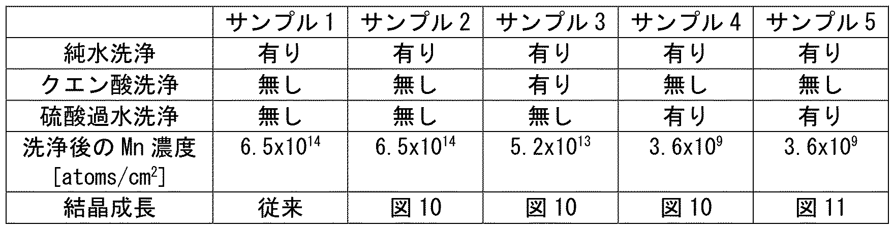
表1は、サンプル1から5に係る炭化珪素基材110の第1主面1におけるMn濃度を示している。表1に示されるように、サンプル1から5に係る炭化珪素基材110の第1主面1におけるMn濃度は、それぞれ6.5×10¹⁴atoms/cm2、6.5×1014atoms/cm2、5.2×1013atoms/cm2、3.6×109atoms/cm2および3.6×109atoms/cm2であった。以上の結果より、硫酸過水洗浄を実施することにより、炭化珪素基材110の第1主面1におけるMn濃度が大幅に低減されていることが確かめられた。
次に、第2化学機械研磨工程(S50)が実施された。第2研磨液は、過マンガン酸塩を含まない。第2研磨液として、フジミインコーポレーテッド社製の「DSC-0902」を使用した。以上のように、サンプル1から5に係る炭化珪素基板100を準備した。サンプル1から5に係る炭化珪素基板100の第1主面1には、複数のピットが形成されていた。
次に、サンプル1から5に係る炭化珪素基板100の第1主面1におけるピットの面密度を測定した。カウントするピットの面積は、3000μm2以上とした。具体的には、レーザーテック株式会社製のWASAVIシリーズ「SICA 6X」を使用して、第1主面1の測定領域においてピット(第1ピット11)の数をカウントした。対物レンズの倍率は、10倍とした。第1主面1の測定領域は、第1主面1において外周縁から2mm以内の領域を除外した領域とした。SICAを使用して観察されたピットの面密度を第2面密度B1(個/cm2)とした。
次に、ノマルスキータイプの光学顕微鏡を使用して、第1主面1におけるピットを観察した。カウントするピットの直径は50μm以上とした。カウントするピットの形状は六角形とした。ノマルスキータイプの光学顕微鏡を使用して観察されたピットの面密度を第3面密度B2(個/cm2)とした。
次に、サンプル1から5に係る炭化珪素基板100の第1主面1上に炭化珪素エピタキシャル層20を形成した。炭化珪素エピタキシャル層20の第3主面3におけるピットの面密度を測定した。カウントするピットの面積は、5000μm2以上とした。具体的には、レーザーテック株式会社製のWASAVIシリーズ「SICA 6X」を使用して、第3主面3の測定領域においてピット(第3ピット21)の数をカウントした。対物レンズの倍率は、10倍とした。第3主面3の測定領域は、第3主面3において外周縁から2mm以内の領域を除外した領域とした。SICAを使用して観察されたピットの面密度を第4面密度C(個/cm2)とした。
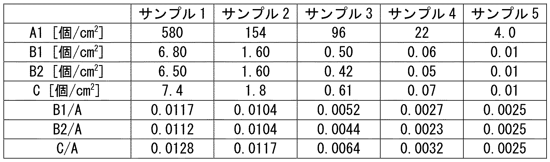
表2は、第1面密度Aと、第2面密度B1と、第3面密度B2と、第4面密度Cと、第2面密度B1を第1面密度Aで除した値(B1/A)と、第3面密度B2を第1面密度Aで除した値(B2/A)と、第4面密度Cを第1面密度Aで除した値(C/A)とを示している。第2面密度B1を第1面密度Aで除した値(B1/A)は、カーボンインクルージョン5の面密度に対する第1ピット11の面密度の比率に対応している。第4面密度Cを第1面密度Aで除した値(C/A)は、カーボンインクルージョン5の面密度に対する第3ピット21の面密度の比率に対応している。
表2に示されるように、サンプル1および2に係る炭化珪素基板100においては、カーボンインクルージョン5の面密度に対する第1ピット11の面密度の比率は、0.008よりも大きかった。サンプル3、4および5に係る炭化珪素基板100においては、カーボンインクルージョン5の面密度に対する第1ピット11の面密度の比率は、0.008以下であった。以上の結果より、サンプル3、4および5に係る炭化珪素基板100においては、カーボンインクルージョン5が第1ピット11となる割合を大幅に低減可能であることが確かめられた。
表2に示されるように、サンプル1および2に係る炭化珪素エピタキシャル基板200においては、カーボンインクルージョン5の面密度に対する第3ピット21の面密度の比率は、0.01よりも大きかった。サンプル3、4および5に係る炭化珪素エピタキシャル基板200においては、カーボンインクルージョン5の面密度に対する第3ピット21の面密度の比率は、0.01以下であった。以上の結果より、サンプル3、4および5に係る炭化珪素エピタキシャル基板200においては、カーボンインクルージョン5が第3ピット21となる割合を大幅に低減可能であることが確かめられた。
本開示は以下に示す実施形態を含む。
(付記1)
主面を備えた炭化珪素基板であって、
前記炭化珪素基板は、複数のカーボンインクルージョンを含み、
前記主面には、複数のピットが形成されており、
前記主面に対して垂直な方向に見て、前記複数のカーボンインクルージョンの各々の最大長さは2μm以上50μm以下であり、かつ、前記複数のピットの各々の面積は3000μm2以上であり、
前記複数のカーボンインクルージョンの面密度に対する前記複数のピットの面密度の比率は、0.008以下である、炭化珪素基板。
(付記2)
前記複数のカーボンインクルージョンの面密度に対する前記ピットの面密度の比率は、0.004以下である、付記1に記載の炭化珪素基板。
(付記3)
前記複数のカーボンインクルージョンの面密度は、155個/cm2以下である、付記1に記載の炭化珪素基板。
(付記4)
前記複数のカーボンインクルージョンの面密度は、100個/cm2以下である、付記3に記載の炭化珪素基板。
(付記5)
前記複数のカーボンインクルージョンの面密度は、50個/cm2以下である、付記4に記載の炭化珪素基板。
(付記6)
前記主面の最大径は、150mm以上である、付記1から付記5のいずれか1項に記載の炭化珪素基板。
(付記7)
炭化珪素基板と、
前記炭化珪素基板上に設けられた炭化珪素エピタキシャル層と、を備え、
前記炭化珪素基板は、複数のカーボンインクルージョンを含み、
前記炭化珪素エピタキシャル層の主面には、複数のピットが形成されており、
前記主面に対して垂直な方向に見て、前記複数のカーボンインクルージョンの各々の最大長さは2μm以上50μm以下であり、かつ、前記複数のピットの各々の面積は5000μm2以上であり、
前記複数のカーボンインクルージョンの面密度に対する前記複数のピットの面密度の比率は、0.01以下である、炭化珪素エピタキシャル基板。
(付記8)
前記複数のカーボンインクルージョンの面密度に対する前記複数のピットの面密度の比率は、0.005以下である、付記7に記載の炭化珪素エピタキシャル基板。
(付記9)
前記主面の最大径は、150mm以上である、付記7または付記8に記載の炭化珪素エピタキシャル基板。
(付記10)
付記7または付記8に記載の炭化珪素エピタキシャル基板を準備する工程と、
前記炭化珪素エピタキシャル基板を加工する工程と、を備えた、炭化珪素半導体装置の製造方法。
(付記11)
第1研磨液を用いて炭化珪素基材に対して化学機械研磨を行う工程と、
前記炭化珪素基材に対して化学機械研磨を行う工程後、洗浄液を用いて前記炭化珪素基材を洗浄する工程と、
前記洗浄液を用いて前記炭化珪素基材を洗浄する工程後、第2研磨液を用いて前記炭化珪素基材に対して化学機械研磨を行う工程と、を備え、
前記炭化珪素基材は、複数のカーボンインクルージョンを含み、
前記第1研磨液は、過マンガン酸塩を含み、
前記第2研磨液は、過マンガン酸塩を含まず、
前記洗浄液は、硫酸と過酸化水素水と超純水との混合液である、炭化珪素基板の製造方法。
(付記12)
前記第2研磨液に用いられる砥粒は、コロイダルシリカを含む、付記11に記載の炭化珪素基板の製造方法。
(付記13)
前記第1研磨液に用いられる砥粒は、コロイダルシリカを含まない、付記11または付記12に記載の炭化珪素基板の製造方法。
(付記14)
前記第2研磨液の水素イオン指数は、7より小さい、付記11または付記12に記載の炭化珪素基板の製造方法。
(付記15)
前記第1研磨液の水素イオン指数は、9より小さい、付記11または付記12に記載の炭化珪素基板の製造方法。
(付記16)
前記硫酸の体積は前記過酸化水素水の体積の10倍であり、かつ前記超純水の体積は前記過酸化水素水の体積の1倍以上10倍以下である、付記11または付記12に記載の炭化珪素基板の製造方法。
(付記17)
前記炭化珪素基材の主面に対して垂直な方向に見て、前記複数のカーボンインクルージョンの各々の最大長さは2μm以上50μm以下である、付記11または付記12に記載の炭化珪素基板の製造方法。
(付記18)
前記複数のカーボンインクルージョンの面密度は、600個/cm2以下である、付記11または付記12に記載の炭化珪素基板の製造方法。
(付記1)
主面を備えた炭化珪素基板であって、
前記炭化珪素基板は、複数のカーボンインクルージョンを含み、
前記主面には、複数のピットが形成されており、
前記主面に対して垂直な方向に見て、前記複数のカーボンインクルージョンの各々の最大長さは2μm以上50μm以下であり、かつ、前記複数のピットの各々の面積は3000μm2以上であり、
前記複数のカーボンインクルージョンの面密度に対する前記複数のピットの面密度の比率は、0.008以下である、炭化珪素基板。
(付記2)
前記複数のカーボンインクルージョンの面密度に対する前記ピットの面密度の比率は、0.004以下である、付記1に記載の炭化珪素基板。
(付記3)
前記複数のカーボンインクルージョンの面密度は、155個/cm2以下である、付記1に記載の炭化珪素基板。
(付記4)
前記複数のカーボンインクルージョンの面密度は、100個/cm2以下である、付記3に記載の炭化珪素基板。
(付記5)
前記複数のカーボンインクルージョンの面密度は、50個/cm2以下である、付記4に記載の炭化珪素基板。
(付記6)
前記主面の最大径は、150mm以上である、付記1から付記5のいずれか1項に記載の炭化珪素基板。
(付記7)
炭化珪素基板と、
前記炭化珪素基板上に設けられた炭化珪素エピタキシャル層と、を備え、
前記炭化珪素基板は、複数のカーボンインクルージョンを含み、
前記炭化珪素エピタキシャル層の主面には、複数のピットが形成されており、
前記主面に対して垂直な方向に見て、前記複数のカーボンインクルージョンの各々の最大長さは2μm以上50μm以下であり、かつ、前記複数のピットの各々の面積は5000μm2以上であり、
前記複数のカーボンインクルージョンの面密度に対する前記複数のピットの面密度の比率は、0.01以下である、炭化珪素エピタキシャル基板。
(付記8)
前記複数のカーボンインクルージョンの面密度に対する前記複数のピットの面密度の比率は、0.005以下である、付記7に記載の炭化珪素エピタキシャル基板。
(付記9)
前記主面の最大径は、150mm以上である、付記7または付記8に記載の炭化珪素エピタキシャル基板。
(付記10)
付記7または付記8に記載の炭化珪素エピタキシャル基板を準備する工程と、
前記炭化珪素エピタキシャル基板を加工する工程と、を備えた、炭化珪素半導体装置の製造方法。
(付記11)
第1研磨液を用いて炭化珪素基材に対して化学機械研磨を行う工程と、
前記炭化珪素基材に対して化学機械研磨を行う工程後、洗浄液を用いて前記炭化珪素基材を洗浄する工程と、
前記洗浄液を用いて前記炭化珪素基材を洗浄する工程後、第2研磨液を用いて前記炭化珪素基材に対して化学機械研磨を行う工程と、を備え、
前記炭化珪素基材は、複数のカーボンインクルージョンを含み、
前記第1研磨液は、過マンガン酸塩を含み、
前記第2研磨液は、過マンガン酸塩を含まず、
前記洗浄液は、硫酸と過酸化水素水と超純水との混合液である、炭化珪素基板の製造方法。
(付記12)
前記第2研磨液に用いられる砥粒は、コロイダルシリカを含む、付記11に記載の炭化珪素基板の製造方法。
(付記13)
前記第1研磨液に用いられる砥粒は、コロイダルシリカを含まない、付記11または付記12に記載の炭化珪素基板の製造方法。
(付記14)
前記第2研磨液の水素イオン指数は、7より小さい、付記11または付記12に記載の炭化珪素基板の製造方法。
(付記15)
前記第1研磨液の水素イオン指数は、9より小さい、付記11または付記12に記載の炭化珪素基板の製造方法。
(付記16)
前記硫酸の体積は前記過酸化水素水の体積の10倍であり、かつ前記超純水の体積は前記過酸化水素水の体積の1倍以上10倍以下である、付記11または付記12に記載の炭化珪素基板の製造方法。
(付記17)
前記炭化珪素基材の主面に対して垂直な方向に見て、前記複数のカーボンインクルージョンの各々の最大長さは2μm以上50μm以下である、付記11または付記12に記載の炭化珪素基板の製造方法。
(付記18)
前記複数のカーボンインクルージョンの面密度は、600個/cm2以下である、付記11または付記12に記載の炭化珪素基板の製造方法。
今回開示された実施の形態および実施例はすべての点で例示であって、制限的なものではないと考えられるべきである。本発明の範囲は上記した説明ではなくて請求の範囲によって示され、請求の範囲と均等の意味、および範囲内でのすべての変更が含まれることが意図される。
1 第1主面(主面)、2 第2主面、3 第3主面(主面)、4 第4主面、5 カーボンインクルージョン、7 オリエンテーションフラット、8 円弧状部、10 炭化珪素領域、11 第1ピット(ピット)、12 第2ピット(ピット)、19 第1外周縁、20 炭化珪素エピタキシャル層、21 第3ピット、22 第4ピット、29 第2外周縁、30 第1研磨液、41 バッファ層、42 ドリフト層、43 穴、44 炭化珪素種基板、45 炭化珪素原料、50 坩堝、51 蓋部、52 原料収容部、53 側壁面、54 底壁面、55 貫通孔、56 トレンチ、57 カバー部材、58 ガイド部材、61 第1測定領域、62 第2測定領域、63 第3測定領域、64 第4測定領域、65 第5測定領域、100 炭化珪素基板、101 第1方向、102 第2方向、110 炭化珪素基材、113 ボディ領域、114 ソース領域、115 ゲート絶縁膜、116 ソース電極、117 マスク、118 コンタクト領域、119 ソース配線、123 ドレイン電極、126 層間絶縁膜、127 ゲート電極、200 炭化珪素エピタキシャル基板、300 炭化珪素単結晶、400 炭化珪素半導体装置、A 第1面密度、B1 第2面密度、B2 第3面密度、C 第4面密度、D1 第1深さ、D2 第2深さ、D3 第3深さ、D4 第4深さ、D5 第5距離、D6 第6距離、E 断面位置、W1 最大径、X 長さ。
Claims (18)
- 主面を備えた炭化珪素基板であって、
前記炭化珪素基板は、複数のカーボンインクルージョンを含み、
前記主面には、複数のピットが形成されており、
前記主面に対して垂直な方向に見て、前記複数のカーボンインクルージョンの各々の最大長さは2μm以上50μm以下であり、かつ、前記複数のピットの各々の面積は3000μm2以上であり、
前記複数のカーボンインクルージョンの面密度に対する前記複数のピットの面密度の比率は、0.008以下である、炭化珪素基板。 - 前記複数のカーボンインクルージョンの面密度に対する前記複数のピットの面密度の比率は、0.004以下である、請求項1に記載の炭化珪素基板。
- 前記複数のカーボンインクルージョンの面密度は、155個/cm2以下である、請求項1または請求項2に記載の炭化珪素基板。
- 前記複数のカーボンインクルージョンの面密度は、100個/cm2以下である、請求項3に記載の炭化珪素基板。
- 前記複数のカーボンインクルージョンの面密度は、50個/cm2以下である、請求項4に記載の炭化珪素基板。
- 前記主面の最大径は、150mm以上である、請求項1から請求項5のいずれか1項に記載の炭化珪素基板。
- 炭化珪素基板と、
前記炭化珪素基板上に設けられた炭化珪素エピタキシャル層と、を備え、
前記炭化珪素基板は、複数のカーボンインクルージョンを含み、
前記炭化珪素エピタキシャル層の主面には、複数のピットが形成されており、
前記主面に対して垂直な方向に見て、前記複数のカーボンインクルージョンの各々の最大長さは2μm以上50μm以下であり、かつ、前記複数のピットの各々の面積は5000μm2以上であり、
前記複数のカーボンインクルージョンの面密度に対する前記複数のピットの面密度の比率は、0.01以下である、炭化珪素エピタキシャル基板。 - 前記複数のカーボンインクルージョンの面密度に対する前記複数のピットの面密度の比率は、0.005以下である、請求項7に記載の炭化珪素エピタキシャル基板。
- 前記主面の最大径は、150mm以上である、請求項7または請求項8に記載の炭化珪素エピタキシャル基板。
- 請求項7から請求項9のいずれか1項に記載の炭化珪素エピタキシャル基板を準備する工程と、
前記炭化珪素エピタキシャル基板を加工する工程と、を備えた、炭化珪素半導体装置の製造方法。 - 第1研磨液を用いて炭化珪素基材に対して化学機械研磨を行う工程と、
前記炭化珪素基材に対して化学機械研磨を行う工程後、洗浄液を用いて前記炭化珪素基材を洗浄する工程と、
前記洗浄液を用いて前記炭化珪素基材を洗浄する工程後、第2研磨液を用いて前記炭化珪素基材に対して化学機械研磨を行う工程と、を備え、
前記炭化珪素基材は、複数のカーボンインクルージョンを含み、
前記第1研磨液は、過マンガン酸塩を含み、
前記第2研磨液は、過マンガン酸塩を含まず、
前記洗浄液は、硫酸と過酸化水素水と超純水との混合液である、炭化珪素基板の製造方法。 - 前記第2研磨液に用いられる砥粒は、コロイダルシリカを含む、請求項11に記載の炭化珪素基板の製造方法。
- 前記第1研磨液に用いられる砥粒は、コロイダルシリカを含まない、請求項11または請求項12に記載の炭化珪素基板の製造方法。
- 前記第2研磨液の水素イオン指数は、7より小さい、請求項11から請求項13のいずれか1項に記載の炭化珪素基板の製造方法。
- 前記第1研磨液の水素イオン指数は、9より小さい、請求項11から請求項14のいずれか1項に記載の炭化珪素基板の製造方法。
- 前記硫酸の体積は前記過酸化水素水の体積の10倍であり、かつ前記超純水の体積は前記過酸化水素水の体積の1倍以上10倍以下である、請求項11から請求項15のいずれか1項に記載の炭化珪素基板の製造方法。
- 前記炭化珪素基材の主面に対して垂直な方向に見て、前記複数のカーボンインクルージョンの各々の最大長さは2μm以上50μm以下である、請求項11から請求項16のいずれか1項に記載の炭化珪素基板の製造方法。
- 前記複数のカーボンインクルージョンの面密度は、600個/cm2以下である、請求項11から請求項17のいずれか1項に記載の炭化珪素基板の製造方法。
Priority Applications (1)
| Application Number | Priority Date | Filing Date | Title |
|---|---|---|---|
| JP2024520296A JPWO2023218809A1 (ja) | 2022-05-11 | 2023-04-05 |
Applications Claiming Priority (2)
| Application Number | Priority Date | Filing Date | Title |
|---|---|---|---|
| JP2022078328 | 2022-05-11 | ||
| JP2022-078328 | 2022-05-11 |
Publications (1)
| Publication Number | Publication Date |
|---|---|
| WO2023218809A1 true WO2023218809A1 (ja) | 2023-11-16 |
Family
ID=88730044
Family Applications (1)
| Application Number | Title | Priority Date | Filing Date |
|---|---|---|---|
| PCT/JP2023/014085 Ceased WO2023218809A1 (ja) | 2022-05-11 | 2023-04-05 | 炭化珪素基板、炭化珪素エピタキシャル基板、炭化珪素基板の製造方法および炭化珪素半導体装置の製造方法 |
Country Status (2)
| Country | Link |
|---|---|
| JP (1) | JPWO2023218809A1 (ja) |
| WO (1) | WO2023218809A1 (ja) |
Citations (5)
| Publication number | Priority date | Publication date | Assignee | Title |
|---|---|---|---|---|
| WO2013035539A1 (ja) * | 2011-09-05 | 2013-03-14 | 旭硝子株式会社 | 研磨剤および研磨方法 |
| WO2013088928A1 (ja) * | 2011-12-14 | 2013-06-20 | 旭硝子株式会社 | 洗浄剤、および炭化ケイ素単結晶基板の製造方法 |
| JP2018039714A (ja) * | 2016-08-31 | 2018-03-15 | 昭和電工株式会社 | SiCエピタキシャルウェハ及びその製造方法、並びに、ラージピット欠陥検出方法、欠陥識別方法 |
| JP2020011878A (ja) * | 2018-07-20 | 2020-01-23 | 株式会社デンソー | 炭化珪素ウェハを含む半導体ウェハおよびSiC半導体装置の製造方法 |
| WO2020235205A1 (ja) * | 2019-05-17 | 2020-11-26 | 住友電気工業株式会社 | 炭化珪素基板 |
-
2023
- 2023-04-05 WO PCT/JP2023/014085 patent/WO2023218809A1/ja not_active Ceased
- 2023-04-05 JP JP2024520296A patent/JPWO2023218809A1/ja active Pending
Patent Citations (5)
| Publication number | Priority date | Publication date | Assignee | Title |
|---|---|---|---|---|
| WO2013035539A1 (ja) * | 2011-09-05 | 2013-03-14 | 旭硝子株式会社 | 研磨剤および研磨方法 |
| WO2013088928A1 (ja) * | 2011-12-14 | 2013-06-20 | 旭硝子株式会社 | 洗浄剤、および炭化ケイ素単結晶基板の製造方法 |
| JP2018039714A (ja) * | 2016-08-31 | 2018-03-15 | 昭和電工株式会社 | SiCエピタキシャルウェハ及びその製造方法、並びに、ラージピット欠陥検出方法、欠陥識別方法 |
| JP2020011878A (ja) * | 2018-07-20 | 2020-01-23 | 株式会社デンソー | 炭化珪素ウェハを含む半導体ウェハおよびSiC半導体装置の製造方法 |
| WO2020235205A1 (ja) * | 2019-05-17 | 2020-11-26 | 住友電気工業株式会社 | 炭化珪素基板 |
Also Published As
| Publication number | Publication date |
|---|---|
| JPWO2023218809A1 (ja) | 2023-11-16 |
Similar Documents
| Publication | Publication Date | Title |
|---|---|---|
| JP6708974B2 (ja) | 炭化珪素エピタキシャル基板、炭化珪素半導体装置の製造方法および炭化珪素半導体装置 | |
| US9070567B2 (en) | Silicon carbide substrate and method of manufacturing silicon carbide substrate | |
| JP2023029930A (ja) | ウエハの洗浄方法及び不純物が低減されたウエハ | |
| WO2023282001A1 (ja) | 炭化珪素エピタキシャル基板、炭化珪素エピタキシャル基板の製造方法および炭化珪素半導体装置の製造方法 | |
| JP7831290B2 (ja) | 炭化珪素エピタキシャル基板および炭化珪素エピタキシャル基板の製造方法 | |
| WO2023218809A1 (ja) | 炭化珪素基板、炭化珪素エピタキシャル基板、炭化珪素基板の製造方法および炭化珪素半導体装置の製造方法 | |
| CN115003866B (zh) | 碳化硅外延衬底及碳化硅半导体器件的制造方法 | |
| JP7772061B2 (ja) | 炭化珪素エピタキシャル基板および炭化珪素半導体装置の製造方法 | |
| US20240363696A1 (en) | Silicon carbide epitaxial substrate and method of manufacturing silicon carbide semiconductor device | |
| JP6590116B2 (ja) | 炭化珪素エピタキシャル基板および炭化珪素半導体装置の製造方法 | |
| WO2023233887A1 (ja) | 炭化珪素基板、炭化珪素エピタキシャル基板および炭化珪素半導体装置の製造方法 | |
| WO2025134535A1 (ja) | 炭化珪素基板、炭化珪素エピタキシャル基板の製造方法、および炭化珪素半導体装置の製造方法 | |
| WO2024127929A1 (ja) | 炭化珪素基板、炭化珪素エピタキシャル基板の製造方法、炭化珪素半導体装置の製造方法および炭化珪素基板の製造方法 | |
| JP2022137673A (ja) | 炭化珪素エピタキシャル基板および炭化珪素半導体装置 | |
| WO2024127944A1 (ja) | 炭化珪素エピタキシャル基板、炭化珪素半導体装置の製造方法および炭化珪素エピタキシャル基板の製造方法 | |
| JP2024113396A (ja) | 炭化珪素基板、炭化珪素エピタキシャル基板、炭化珪素基板の製造方法および炭化珪素半導体装置の製造方法 | |
| US20250393275A1 (en) | Silicon carbide epitaxial substrate and method of manufacturing silicon carbide semiconductor device | |
| WO2024232252A1 (ja) | 炭化珪素エピタキシャル基板および炭化珪素半導体装置の製造方法 | |
| WO2024034267A1 (ja) | 炭化珪素基板、炭化珪素エピタキシャル基板および炭化珪素半導体装置の製造方法 | |
| WO2025004788A1 (ja) | 炭化珪素エピタキシャル基板、炭化珪素半導体装置の製造方法、および炭化珪素半導体装置 | |
| WO2024057845A1 (ja) | 炭化珪素基板、炭化珪素エピタキシャル基板および炭化珪素半導体装置の製造方法 | |
| JP2025139953A (ja) | 炭化珪素基板、炭化珪素基板の製造方法、炭化珪素エピタキシャル基板の製造方法、炭化珪素エピタキシャル基板、炭化珪素半導体装置の製造方法、および炭化珪素半導体装置 | |
| WO2025084082A1 (ja) | 炭化珪素エピタキシャル基板および炭化珪素半導体装置の製造方法 |
Legal Events
| Date | Code | Title | Description |
|---|---|---|---|
| 121 | Ep: the epo has been informed by wipo that ep was designated in this application |
Ref document number: 23803292 Country of ref document: EP Kind code of ref document: A1 |
|
| ENP | Entry into the national phase |
Ref document number: 2024520296 Country of ref document: JP Kind code of ref document: A |
|
| NENP | Non-entry into the national phase |
Ref country code: DE |
|
| 122 | Ep: pct application non-entry in european phase |
Ref document number: 23803292 Country of ref document: EP Kind code of ref document: A1 |