WO2023218755A1 - 運転支援装置 - Google Patents
運転支援装置 Download PDFInfo
- Publication number
- WO2023218755A1 WO2023218755A1 PCT/JP2023/010136 JP2023010136W WO2023218755A1 WO 2023218755 A1 WO2023218755 A1 WO 2023218755A1 JP 2023010136 W JP2023010136 W JP 2023010136W WO 2023218755 A1 WO2023218755 A1 WO 2023218755A1
- Authority
- WO
- WIPO (PCT)
- Prior art keywords
- vehicle
- unit
- obstacle
- driving support
- observation
- Prior art date
- Legal status (The legal status is an assumption and is not a legal conclusion. Google has not performed a legal analysis and makes no representation as to the accuracy of the status listed.)
- Ceased
Links
Images












Classifications
-
- B—PERFORMING OPERATIONS; TRANSPORTING
- B60—VEHICLES IN GENERAL
- B60W—CONJOINT CONTROL OF VEHICLE SUB-UNITS OF DIFFERENT TYPE OR DIFFERENT FUNCTION; CONTROL SYSTEMS SPECIALLY ADAPTED FOR HYBRID VEHICLES; ROAD VEHICLE DRIVE CONTROL SYSTEMS FOR PURPOSES NOT RELATED TO THE CONTROL OF A PARTICULAR SUB-UNIT
- B60W30/00—Purposes of road vehicle drive control systems not related to the control of a particular sub-unit, e.g. of systems using conjoint control of vehicle sub-units
- B60W30/08—Active safety systems predicting or avoiding probable or impending collision or attempting to minimise its consequences
- B60W30/09—Taking automatic action to avoid collision, e.g. braking and steering
-
- B—PERFORMING OPERATIONS; TRANSPORTING
- B60—VEHICLES IN GENERAL
- B60W—CONJOINT CONTROL OF VEHICLE SUB-UNITS OF DIFFERENT TYPE OR DIFFERENT FUNCTION; CONTROL SYSTEMS SPECIALLY ADAPTED FOR HYBRID VEHICLES; ROAD VEHICLE DRIVE CONTROL SYSTEMS FOR PURPOSES NOT RELATED TO THE CONTROL OF A PARTICULAR SUB-UNIT
- B60W60/00—Drive control systems specially adapted for autonomous road vehicles
- B60W60/001—Planning or execution of driving tasks
- B60W60/0013—Planning or execution of driving tasks specially adapted for occupant comfort
-
- B—PERFORMING OPERATIONS; TRANSPORTING
- B60—VEHICLES IN GENERAL
- B60W—CONJOINT CONTROL OF VEHICLE SUB-UNITS OF DIFFERENT TYPE OR DIFFERENT FUNCTION; CONTROL SYSTEMS SPECIALLY ADAPTED FOR HYBRID VEHICLES; ROAD VEHICLE DRIVE CONTROL SYSTEMS FOR PURPOSES NOT RELATED TO THE CONTROL OF A PARTICULAR SUB-UNIT
- B60W30/00—Purposes of road vehicle drive control systems not related to the control of a particular sub-unit, e.g. of systems using conjoint control of vehicle sub-units
- B60W30/18—Propelling the vehicle
- B60W30/18009—Propelling the vehicle related to particular drive situations
- B60W30/18036—Reversing
-
- B—PERFORMING OPERATIONS; TRANSPORTING
- B60—VEHICLES IN GENERAL
- B60W—CONJOINT CONTROL OF VEHICLE SUB-UNITS OF DIFFERENT TYPE OR DIFFERENT FUNCTION; CONTROL SYSTEMS SPECIALLY ADAPTED FOR HYBRID VEHICLES; ROAD VEHICLE DRIVE CONTROL SYSTEMS FOR PURPOSES NOT RELATED TO THE CONTROL OF A PARTICULAR SUB-UNIT
- B60W50/00—Details of control systems for road vehicle drive control not related to the control of a particular sub-unit, e.g. process diagnostic or vehicle driver interfaces
- B60W50/02—Ensuring safety in case of control system failures, e.g. by diagnosing, circumventing or fixing failures
- B60W50/0205—Diagnosing or detecting failures; Failure detection models
-
- G—PHYSICS
- G08—SIGNALLING
- G08G—TRAFFIC CONTROL SYSTEMS
- G08G1/00—Traffic control systems for road vehicles
- G08G1/09—Arrangements for giving variable traffic instructions
- G08G1/0962—Arrangements for giving variable traffic instructions having an indicator mounted inside the vehicle, e.g. giving voice messages
- G08G1/0967—Systems involving transmission of highway information, e.g. weather, speed limits
- G08G1/096766—Systems involving transmission of highway information, e.g. weather, speed limits where the system is characterised by the origin of the information transmission
- G08G1/096791—Systems involving transmission of highway information, e.g. weather, speed limits where the system is characterised by the origin of the information transmission where the origin of the information is another vehicle
-
- G—PHYSICS
- G08—SIGNALLING
- G08G—TRAFFIC CONTROL SYSTEMS
- G08G1/00—Traffic control systems for road vehicles
- G08G1/16—Anti-collision systems
- G08G1/161—Decentralised systems, e.g. inter-vehicle communication
- G08G1/162—Decentralised systems, e.g. inter-vehicle communication event-triggered
-
- G—PHYSICS
- G08—SIGNALLING
- G08G—TRAFFIC CONTROL SYSTEMS
- G08G1/00—Traffic control systems for road vehicles
- G08G1/16—Anti-collision systems
- G08G1/165—Anti-collision systems for passive traffic, e.g. including static obstacles, trees
-
- G—PHYSICS
- G08—SIGNALLING
- G08G—TRAFFIC CONTROL SYSTEMS
- G08G1/00—Traffic control systems for road vehicles
- G08G1/16—Anti-collision systems
- G08G1/166—Anti-collision systems for active traffic, e.g. moving vehicles, pedestrians, bikes
-
- G—PHYSICS
- G08—SIGNALLING
- G08G—TRAFFIC CONTROL SYSTEMS
- G08G1/00—Traffic control systems for road vehicles
- G08G1/22—Platooning, i.e. convoy of communicating vehicles
-
- B—PERFORMING OPERATIONS; TRANSPORTING
- B60—VEHICLES IN GENERAL
- B60W—CONJOINT CONTROL OF VEHICLE SUB-UNITS OF DIFFERENT TYPE OR DIFFERENT FUNCTION; CONTROL SYSTEMS SPECIALLY ADAPTED FOR HYBRID VEHICLES; ROAD VEHICLE DRIVE CONTROL SYSTEMS FOR PURPOSES NOT RELATED TO THE CONTROL OF A PARTICULAR SUB-UNIT
- B60W2520/00—Input parameters relating to overall vehicle dynamics
- B60W2520/06—Direction of travel
-
- B—PERFORMING OPERATIONS; TRANSPORTING
- B60—VEHICLES IN GENERAL
- B60W—CONJOINT CONTROL OF VEHICLE SUB-UNITS OF DIFFERENT TYPE OR DIFFERENT FUNCTION; CONTROL SYSTEMS SPECIALLY ADAPTED FOR HYBRID VEHICLES; ROAD VEHICLE DRIVE CONTROL SYSTEMS FOR PURPOSES NOT RELATED TO THE CONTROL OF A PARTICULAR SUB-UNIT
- B60W2554/00—Input parameters relating to objects
- B60W2554/20—Static objects
-
- B—PERFORMING OPERATIONS; TRANSPORTING
- B60—VEHICLES IN GENERAL
- B60W—CONJOINT CONTROL OF VEHICLE SUB-UNITS OF DIFFERENT TYPE OR DIFFERENT FUNCTION; CONTROL SYSTEMS SPECIALLY ADAPTED FOR HYBRID VEHICLES; ROAD VEHICLE DRIVE CONTROL SYSTEMS FOR PURPOSES NOT RELATED TO THE CONTROL OF A PARTICULAR SUB-UNIT
- B60W2554/00—Input parameters relating to objects
- B60W2554/40—Dynamic objects, e.g. animals, windblown objects
- B60W2554/402—Type
-
- B—PERFORMING OPERATIONS; TRANSPORTING
- B60—VEHICLES IN GENERAL
- B60W—CONJOINT CONTROL OF VEHICLE SUB-UNITS OF DIFFERENT TYPE OR DIFFERENT FUNCTION; CONTROL SYSTEMS SPECIALLY ADAPTED FOR HYBRID VEHICLES; ROAD VEHICLE DRIVE CONTROL SYSTEMS FOR PURPOSES NOT RELATED TO THE CONTROL OF A PARTICULAR SUB-UNIT
- B60W2554/00—Input parameters relating to objects
- B60W2554/40—Dynamic objects, e.g. animals, windblown objects
- B60W2554/404—Characteristics
- B60W2554/4041—Position
-
- B—PERFORMING OPERATIONS; TRANSPORTING
- B60—VEHICLES IN GENERAL
- B60W—CONJOINT CONTROL OF VEHICLE SUB-UNITS OF DIFFERENT TYPE OR DIFFERENT FUNCTION; CONTROL SYSTEMS SPECIALLY ADAPTED FOR HYBRID VEHICLES; ROAD VEHICLE DRIVE CONTROL SYSTEMS FOR PURPOSES NOT RELATED TO THE CONTROL OF A PARTICULAR SUB-UNIT
- B60W2556/00—Input parameters relating to data
- B60W2556/10—Historical data
-
- B—PERFORMING OPERATIONS; TRANSPORTING
- B60—VEHICLES IN GENERAL
- B60W—CONJOINT CONTROL OF VEHICLE SUB-UNITS OF DIFFERENT TYPE OR DIFFERENT FUNCTION; CONTROL SYSTEMS SPECIALLY ADAPTED FOR HYBRID VEHICLES; ROAD VEHICLE DRIVE CONTROL SYSTEMS FOR PURPOSES NOT RELATED TO THE CONTROL OF A PARTICULAR SUB-UNIT
- B60W2556/00—Input parameters relating to data
- B60W2556/40—High definition maps
-
- B—PERFORMING OPERATIONS; TRANSPORTING
- B60—VEHICLES IN GENERAL
- B60W—CONJOINT CONTROL OF VEHICLE SUB-UNITS OF DIFFERENT TYPE OR DIFFERENT FUNCTION; CONTROL SYSTEMS SPECIALLY ADAPTED FOR HYBRID VEHICLES; ROAD VEHICLE DRIVE CONTROL SYSTEMS FOR PURPOSES NOT RELATED TO THE CONTROL OF A PARTICULAR SUB-UNIT
- B60W2556/00—Input parameters relating to data
- B60W2556/45—External transmission of data to or from the vehicle
- B60W2556/65—Data transmitted between vehicles
Definitions
- the present invention relates to a driving support device that supports driving of a vehicle.
- One of the driving support systems in the low speed range is a reverse support system that stores the driving history on narrow roads and supports backward driving by replaying the stored driving route in the event of a dead end, passing each other, etc.
- Patent Document 1 the driving history and surrounding environment when moving forward are stored, the surrounding environment stored when reversing is compared with the current surrounding environment, and if there is no difference, assistance is provided by reverse playback, and if there is a difference, support is provided. discloses a method for alerting drivers.
- the obstacle may be a moving object such as a stopped vehicle or a pedestrian that moves when reversing. It is not possible to determine whether the vehicle is lost or not detected due to a sensor failure when reversing, and it is not possible to perform reverse playback.
- the following vehicle is memorized, so if, for example, the following vehicle disappears on the way, the comparison cannot be performed correctly when reversing, and reverse playback is performed. Can not.
- the present invention has been made in view of the above circumstances, and aims to provide a safe and convenient driving support device in situations where reverse regeneration cannot be performed, such as when passing each other on a narrow road.
- the driving support device includes a driving operation acquisition unit that acquires the driving operation of the driver of the own vehicle, and a first observation unit that observes the surrounding situation of the own vehicle.
- a second observation unit that acquires second observation information of a first observation information acquisition unit that acquires information and a second observation unit that observes a direction different from the first observation unit in the surrounding situation of the own vehicle.
- an information acquisition unit which uses first observation information of the first observation unit and second observation information of the second observation unit when the vehicle is traveling to determine at least stationary objects and other obstacles among the obstacles.
- an obstacle discriminating section a storage section that stores at least a stationary object among the obstacles discriminated by the obstacle discriminating section and the driving operation acquired by the driving operation acquisition section; a surrounding situation collation unit that collates the obstacles obtained from the first observation unit or the second observation unit and the obstacles stored in the storage unit when the own vehicle travels the route traveled by the own vehicle; and a driving support control unit that supports driving based on the driving operation stored in the storage unit when the own vehicle is running, and the driving support control unit is configured to check the verification results obtained by the surrounding situation verification unit.
- the present invention is characterized in that it is determined whether or not to implement driving support depending on the situation.
- the driving support device includes a driving operation acquisition section that acquires the driving operation of the driver of the own vehicle, and a forward observation information acquisition section that acquires forward observation information of the forward observation section that observes the surrounding situation in front of the own vehicle.
- a rear observation information acquisition unit that acquires rear observation information of a rear observation unit that observes the surrounding situation behind the own vehicle, and forward observation information of the front observation unit and rear observation information of the rear observation unit when the own vehicle moves forward.
- an obstacle discrimination unit that discriminates between at least stationary objects and others among the obstacles using the above-described method; and at least a stationary object among the obstacles discriminated by the obstacle discrimination unit and the driving operation acquired by the driving operation acquisition unit.
- a surrounding situation matching unit that compares an obstacle behind the vehicle obtained from the rear observation unit with a stationary object stored by the storage unit when the vehicle is reversing along the forward route; a reverse regeneration backward support control unit that supports backward driving by reproducing the driving operation stored in the storage unit when the own vehicle is moving forward, when the own vehicle is reversing the forward route;
- the control unit is characterized in that it determines whether or not to perform reverse playback support in accordance with the verification result obtained by the surrounding situation verification unit.
- moving objects such as stopped vehicles and pedestrians are stored separately, it is possible to recognize that a moving object such as a stopped vehicle or a pedestrian that was present when moving forward has moved and been lost when reversing. I can do it. Similarly, if an area stored as an immovable obstacle (stationary object) cannot currently be detected, it can be recognized that the vehicle cannot be detected due to a sensor malfunction or the like when reversing.
- an immovable obstacle stationary object
- the following vehicle and surrounding obstacles are distinguished and memorized, so even if, for example, the following vehicle disappears midway, it can be compared when reversing. Can be carried out correctly.
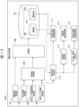
- FIG. 1 is a system configuration diagram of a driving support device according to a first embodiment of the present invention.
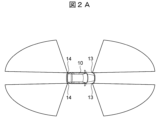
- FIG. 2 is an overhead view showing an example of a sensor mounting configuration and a sensor detection range (an example in which sensors are mounted at four corners of a vehicle) according to a first embodiment of the present invention.
- FIG. 7 is an overhead view showing another example of the sensor mounting configuration and sensor detection range (an example in which the sensors are attached to left and right side mirrors) according to the first embodiment of the present invention.
- FIG. 3 is an overhead view showing another example of the sensor mounting configuration and sensor detection range (an example in which the sensor is attached to the front and rear bumpers of the vehicle) according to the first embodiment of the present invention.
- FIG. 1 is a system configuration diagram of a driving support device according to a first embodiment of the present invention.
- FIG. 2 is an overhead view showing an example of a sensor mounting configuration and a sensor detection range (an example in which sensors are mounted at four corners of a vehicle) according to a first embodiment of the present invention
- FIG. 4 is an overhead view showing another example of the sensor mounting configuration and sensor detection range (an example in which sensors are installed at the front and rear of the vehicle) according to the first embodiment of the present invention.
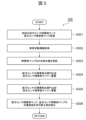
- 5 is a flowchart of the obstacle determination unit according to the first embodiment of the present invention.
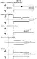
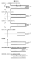
- An example of obstacle discrimination processing by the obstacle discrimination unit according to the first embodiment of the present invention is shown, in which (a) is an example of a scene, and (b) is a position on the left side of FIG. 4(a) (time t - ⁇ t).
- (c) is the front sensor obstacle map created at the left position (time t- ⁇ t) of FIG. 4(a)
- (d) is the detection status of sensors 13 and 14 of FIG. 4(a).
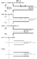
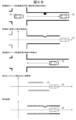
- FIG. 3 is an explanatory diagram of an example of obstacle discrimination processing, surrounding situation comparison processing, and reverse playback support control (when a moving object such as a pedestrian is moving) according to a known technique (when there is no object type discrimination);
- FIG. 3 is an explanatory diagram of an example of obstacle discrimination processing, surrounding situation comparison processing, and reverse playback support control (when a moving object such as a pedestrian is moving) according to a known technique (when there is no object type discrimination);
- FIG. 6 is an explanatory diagram of another example of obstacle discrimination processing, surrounding situation comparison processing, and reverse playback support control (when no object such as a telephone pole is detected) according to known technology (when there is no object type discrimination);
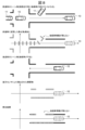
- FIG. 7 is an explanatory diagram of an example of obstacle discrimination processing, surrounding situation comparison processing, and reverse playback support control (when a moving object such as a pedestrian moves) according to the present embodiment (when object type discrimination is included);
- FIG. 7 is an explanatory diagram of another example of obstacle discrimination processing, surrounding situation comparison processing, and reverse playback support control (when no object such as a telephone pole is detected) according to the present embodiment (when object type discrimination is present);
- FIG. 7 is an explanatory diagram of another example of obstacle discrimination processing, surrounding situation comparison processing, and reverse playback support control (when no object such as a telephone pole is detected) according to the present embodiment (when object type discrimination is present);
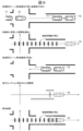
- FIG. 7 is an explanatory diagram of yet another example of obstacle discrimination processing, surrounding situation comparison processing, and reverse reproduction backing support control (when a following vehicle disappears on the way) according to the known technology (when there is no object type discrimination);
- FIG. 7 is an explanatory diagram of still another example (when the following vehicle disappears on the way) of the obstacle discrimination process, the surrounding situation comparison process, and the reverse reproduction backing support control according to the present embodiment (when there is object type discrimination);
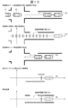
- FIG. 7 is an explanatory diagram of yet another example of obstacle discrimination processing, surrounding situation comparison processing, and reverse reproduction backing support control (when there is a following vehicle) according to the known technology (when there is no object type discrimination);
- FIG. 7 is an explanatory diagram of yet another example of obstacle discrimination processing, surrounding situation comparison processing, and reverse reproduction backing support control (when there is a following vehicle) according to the known technology (when there is no object type discrimination);
- FIG. 7 is an explanatory diagram of still another example (when a following vehicle exists) of obstacle discrimination processing, surrounding situation comparison processing, and reverse reproduction backing support control according to the present embodiment (when there is object type discrimination);
- 5 is a flowchart of a following vehicle detection unit according to the first embodiment of the present invention.
- 5 is a flowchart of a passing space determination unit according to the first embodiment of the present invention.
- FIG. 2 is a system configuration diagram of a driving support device according to a second embodiment of the present invention.
- FIG. 7 is a bird's-eye view showing an example of a sensor mounting configuration and a sensor detection range according to a second embodiment of the present invention (an example in which a front camera is installed at the front center, and rear sensors are installed at rear left and right sides);
- FIG. 7 is an overhead view showing another example of the sensor mounting configuration and sensor detection range according to the second embodiment of the present invention (an example in which the front camera is attached to the center of the front, and the rear sensors for the rear side are attached to the left and right side mirrors).
- FIG. 3 is an overhead view showing another example of the sensor mounting configuration and sensor detection range (an example in which the front camera is mounted at the center of the front and the rear sensor is mounted on the bumper at the rear of the vehicle) according to the first embodiment of the present invention.
- FIG. 7 is an overhead view showing another example of the sensor mounting configuration and sensor detection range (an example in which the front camera is mounted at the front center and the rear sensor is mounted at the rear of the vehicle) according to the first embodiment of the present invention.
- FIG. 7 is a flowchart of an obstacle determination unit according to a second embodiment of the present invention.
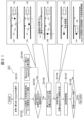
- An example of obstacle discrimination processing by the obstacle discrimination unit according to the second embodiment of the present invention is shown, in which (a) is an example of a scene, and (b) is a position on the left side of FIG. 16(a) (time t- ⁇ t).
- (c) is the front sensor obstacle map created at the left position (time t- ⁇ t) in FIG. 16(a)
- (d) is the detection status of the sensors 23 and 14 in FIG. 16(a).
- the rear sensor obstacle map created at the left position (time t- ⁇ t) (e) shows the detection status of sensors 23 and 14 at the right position (time t) in FIG.
- FIG. 7 is a system configuration diagram of a driving support device according to a third embodiment of the present invention.
- FIG. 4 is an explanatory diagram of the effects of the reverse support control of the present embodiment.
- 7 is a flowchart of a reroute generation driving support control unit according to a third embodiment of the present invention.
- FIG. 4 is a system configuration diagram of a driving support device according to a fourth embodiment of the present invention. Diagram of communication connections between own vehicle and other vehicles. 7 is a flowchart of a following vehicle following control unit according to a fourth embodiment of the present invention.
- FIG. 3 is an explanatory diagram of an example of object type discrimination means of the driving support device according to the present invention.
- FIG. 7 is an explanatory diagram of another example of the object type discrimination means of the driving support device according to the present invention.
- FIG. 2 is an explanatory diagram of an example of an application scene and an example of operation of the driving support device according to the present invention.
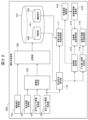
- FIG. 1 is a system configuration diagram of a driving support device 100 according to a first embodiment of the present invention.
- the driving support device 100 is mounted on a vehicle (self-vehicle) 10, and is a device that supports a driver's driving operation by electronically controlling each functional unit included in the vehicle 10.
- the driving support device 100 of the present embodiment supports the backward movement of the vehicle 10 (that is, the driving operation when the vehicle 10 moves backward) based on the information stored when the vehicle 10 moves forward, for example, when passing each other on a narrow road. (reverse support control).
- the driving support device 100 is a computer that controls the vehicle 10, and acquires driving operation acquisition section 101, vehicle behavior acquisition section 102, front sensor information acquisition section 103, and rear sensor information by executing a program stored in a storage medium.
- the driving operation acquisition unit 101 acquires the driving operation (information) of the driver of the vehicle 10 from various sensors mounted on the vehicle 10 .
- the driving operation acquisition unit 101 acquires the driver's driving operations (information) regarding acceleration/deceleration, steering, shift position, etc. of the vehicle 10, such as accelerator operation, brake operation, steering operation (steering angle), shift lever operation, etc. .
- the vehicle behavior acquisition unit 102 acquires the behavior (information) of the vehicle 10 from various sensors mounted on the vehicle 10.
- the vehicle behavior acquisition unit 102 acquires behaviors (information) such as wheel speed (vehicle speed), acceleration, and lateral speed (yaw angle) of the vehicle 10, for example.
- the driving support device 100 is connected to a front sensor 13 (FIGS. 2A to 2D) mounted on the vehicle 10.
- the front sensor 13 has a function as a front observation unit that observes the surrounding situation in front of the vehicle (self-vehicle) 10.
- the front sensor 13 is, for example, a camera that measures the distance to surrounding objects using images, a radar that measures the distance to surrounding objects using millimeter waves or laser light, or a radar that measures the distance to surrounding objects using ultrasonic waves. A sonar or the like can be used for measurement.
- the front sensor 13 outputs point cloud data representing the coordinates of the boundary portion of surrounding objects to the driving support device 100.
- the front sensor information acquisition unit 103 acquires observation information in front of the vehicle 10 from the front sensor 13 (sensor information having point cloud data that detects peripheral objects (obstacles) in front of the vehicle 10).
- the driving support device 100 is connected to a rear sensor 14 (FIGS. 2A to 2D) mounted on the vehicle 10.
- the rear sensor 14 has a function as a rear observation unit that observes the surrounding situation behind the vehicle (self-vehicle) 10.
- the rear sensor 14 includes, for example, a camera that measures the distance to surrounding objects using images, a radar that measures the distance to surrounding objects using millimeter waves or laser light, and a radar that measures the distance to surrounding objects using ultrasonic waves. A sonar or the like can be used for measurement.
- the rear sensor 14 outputs point cloud data representing the coordinates of the boundary portions of surrounding objects to the driving support device 100.
- the rear sensor information acquisition unit 104 acquires observation information behind the vehicle 10 (sensor information having point cloud data that detects surrounding objects (obstacles) behind the vehicle 10) from the rear sensor 14.
- (Configuration of sensors 13 and 14) 2A, B, C, and D show examples of mounting the sensors 13 and 14 according to the first embodiment of the present invention.
- the front sensor 13 and the rear sensor 14 are attached to the vehicle 10 so as to observe different directions in the surrounding situation of the vehicle 10. Further, the front sensor 13 and the rear sensor 14 are configured using sensors having the same characteristics, such as a camera, radar, and sonar.
- the front sensor 13 and the rear sensor 14 are attached to the four corners of the vehicle 10 at the front, rear, left, and right. That is, (a pair of) front sensors 13, 13 are attached to the front left and right sides of the vehicle 10 so as to face the front sides (front left side, front right side) of the vehicle 10, (a pair of) rear sensors 14, 14 are attached to the rear left and right sides of the vehicle 10 so as to face the rear side (rear left side, rear right side) of the vehicle 10. Further, as shown in FIG. 2B, the front sensor 13 and the rear sensor 14 (for example, a camera) are attached to the left and right side mirrors of the vehicle 10.
- the (pair of) front sensors 13, 13 are attached to the left and right side mirrors of the vehicle 10 so as to face the front sides (front left side, front right side) of the vehicle 10
- the (pair of) rear sensors 14 , 14 are attached to the left and right side mirrors of the vehicle 10 so as to face the rear side (rear left side, rear right side) of the vehicle 10.
- the front sensor 13 and the rear sensor 14 are attached to the front and rear bumpers of the vehicle 10.
- the plurality of front sensors 13 are attached to the front bumper of the vehicle 10 so as to face the front of the vehicle 10 as a whole
- the plurality of rear sensors 14 are attached to the rear bumper of the vehicle 10 so as to face the vehicle 10 as a whole. It is attached so that it faces towards the rear.
- the front sensor 13 and the rear sensor 14 are attached to the front and back center of the vehicle 10. That is, the front sensor 13 is attached to the center of the front of the vehicle 10 so as to face the front of the vehicle 10, and the rear sensor 14 is attached to the center of the rear of the vehicle 10 so as to face the rear of the vehicle 10.
- the number, arrangement, etc. of the front sensor 13 and the rear sensor 14 are not limited to the examples shown in FIGS. 2A to 2D.
- the obstacle determination unit 105 uses (integrates) the sensor information acquired from the front sensor information acquisition unit 103 and the rear sensor information acquisition unit 104 to determine the object type of obstacles around the vehicle 10 (in front and behind). Discern.
- the obstacle discrimination unit 105 discriminates at least stationary objects and other objects (moving objects, etc.) as object types.
- FIG. 3 shows a flowchart of the obstacle determination unit 105 according to the first embodiment of the present invention.
- the flow shown in FIG. 3 is repeatedly executed (regularly) at a predetermined processing cycle.
- FIG. 4 shows an example of obstacle discrimination processing by the obstacle discrimination unit 105 according to the first embodiment of the present invention.
- FIG. 4(a) shows a scene where the vehicle 10 is traveling from left to right on a narrow road.
- FIG. 4(b) shows the detection status of the sensors 13 and 14 at the left position (time t- ⁇ t) of FIG. 4(a), and FIG. 4(c) and FIG.
- a front sensor obstacle map and a rear sensor obstacle map created at the left position (time t- ⁇ t) are shown.
- FIG. 4(e) shows the detection status of the sensors 13 and 14 at the right position (time t) in FIG. 4(a), and
- FIG. 4(f) and FIG. 4(g) show the detection status on the right side of FIG. 4(a).
- a front sensor obstacle map and a rear sensor obstacle map created at the position (time t) are shown.
- FIG. 4(h) shows a type map created by comparing (superimposing) the front sensor obstacle map of FIG. 4(f) and the rear sensor obstacle map of FIG. 4(g).
- a group of points (black dots) detected by both sensors 13 and 14 at the same position is determined as a stationary object.
- the obstacle discrimination unit 105 stores sensor information (point cloud information detecting obstacles in front and behind the vehicle 10) acquired from the front sensor information acquisition unit 103 and the rear sensor information acquisition unit 104 in a map stored in a memory in advance. By arranging the front sensor obstacle map and the rear sensor obstacle map, a front sensor obstacle map and a rear sensor obstacle map are created (updated) and stored in the memory (FIGS. 4(b), (c), and (d)).
- the obstacle determination unit 105 stores the previous (time t- ⁇ t, ⁇ t: processing cycle) front sensor obstacle map and rear sensor obstacle map stored in the memory as described above. (Fig. 4(c), (d)).
- vehicle behavior information is acquired from the vehicle behavior acquisition unit 102.
- the own vehicle position in the front sensor obstacle map and the rear sensor obstacle map is updated using the front sensor obstacle map and rear sensor obstacle map obtained in S301 and the vehicle behavior information obtained in S302. (Fig. 4(f), (g)).
- the obstacle point group Pf[p of the front sensor 13, which is the sensor information (point group information that detected the obstacle in front of the vehicle 10) (currently (time t)) acquired from the front sensor information acquisition unit 103, is ] is superimposed on the front sensor obstacle map (of the previous time (time t- ⁇ t)) acquired in S301 (FIG. 4(f)).
- the obstacle point group Pr[q of the rear sensor 14 is acquired from the rear sensor information acquisition unit 104 (currently (time t)) and is the sensor information (point cloud information that detected obstacles behind the vehicle 10). ] is superimposed on the rear sensor obstacle map (of the previous time (time t- ⁇ t)) acquired in S301 (FIG. 4(g)).
- the common area (point cloud) of the front sensor obstacle map created in S304 (currently (time t)) and the rear sensor obstacle map created in S305 (currently (time t)) is determined, and the common area is calculated.
- the region (point group) is extracted as a stationary object (Fig. 4(h)).
- the obstacle discrimination unit 105 discriminates the same obstacle (point cloud) detected by both the front sensor 13 (front sensor obstacle map) and the rear sensor 14 (rear sensor obstacle map) as a stationary object. do.
- the obstacle discrimination unit 105 discriminates at least stationary objects and other obstacles (moving objects, etc.) among the obstacles around the own vehicle 10.
- the storage unit 106 stores the obstacles (information) acquired from the obstacle determination unit 105 (including the object type (information) of the obstacle determined by the obstacle determination unit 105) and the driving operation acquired from the driving operation acquisition unit 101. (information) is stored in the memory 107 as an obstacle (information) 108 and a driving operation (information) 109.
- the storage unit 106 stores at least stationary objects among the obstacles determined by the obstacle determination unit 105 in the memory 107 as obstacles (information) 108 .
- the surrounding situation verification unit 110 is executed when the vehicle 10 is reversing the route along which it has advanced. More specifically, it is performed when there is a request for implementation of reverse support control from the driver of the vehicle 10 moving forward.
- a request from the driver to implement the reverse support control can be recognized, for example, through an operation of a switch input or a touch panel input provided on the vehicle 10, voice recognition, an operation of switching the shift lever to reverse, or the like.
- the surrounding situation collation unit 110 uses sensor information acquired from the rear sensor information acquisition unit 104 (in other words, obstacle information behind the own vehicle acquired from the rear sensor 14) and obstacles stored in the memory 107 by the storage unit 106. (Information) Verify 108 stationary objects.
- the surrounding situation matching unit 110 determines that the obstacle (information) 108 stored in the memory 107 by the storage unit 106 does not exist in the stationary object, and the current sensor information acquired from the rear sensor information acquisition unit 104 (in other words, An object existing in the current obstacle information behind the vehicle obtained by the sensor 14 is determined to be a moving object.
- the surrounding situation matching unit 110 also detects the current sensor information (in other words, the rear sensor Objects that do not exist in the current obstacle information behind the vehicle obtained from 14 are determined to be objects that are highly likely to have malfunctions in the sensors 13 and 14.
- the reverse regeneration backward support control unit 111 is executed when the vehicle 10 moves backward along the forward route.
- the reverse regeneration backing support control unit 111 acquires the driving operation (information) 109 stored in the memory 107 by the storage unit 106 when the vehicle 10 is moving forward, and supports backward driving (implements backing support) by reproducing the driving operation (information) 109 in the reverse direction. That is, the reverse reproduction backward support control unit 111 controls the steering device, the drive device, the braking device, and the transmission device so that the driving operation (information) 109 stored in the memory 107 by the storage unit 106 is reversely reproduced when the vehicle 10 moves forward. It supports backward driving by controlling the following.
- the reverse playback support control unit 111 determines whether to implement reverse playback support according to the verification result obtained by the surrounding situation verification unit 110.
- the reverse playback support control unit 111 does not perform reverse playback support if a moving object is included during the verification performed by the surrounding situation matching unit 110.
- the reverse regeneration backing support control unit 111 does not perform reverse regeneration backing support and alerts the driver if an object that is likely to cause a malfunction of the sensors 13 and 14 is included when the surrounding situation matching unit 110 verifies the situation. do.
- the driver's attention can be alerted, for example, via a display provided in the driver's seat, a meter panel, a display device such as a warning light, or a notification device such as a sound generating device such as a speaker or a buzzer.
- the reverse regeneration backward support control unit 111 supports backward driving by reversely reproducing the driving operation (information) 109 stored in the memory 107 by the storage unit 106 when the vehicle 10 is moving forward.
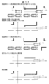
- FIG. 5A is an example of processing using a known technique (when there is no object type discrimination) (when a moving object such as a pedestrian is moving)
- FIG. 5B is another example of processing using a known technique (when there is no object type discrimination).
- objects such as utility poles are not detected.
- FIGS. 5A and 5B show similar conditions (obstacles that are not currently detected by the rear sensor 14 (moving objects such as pedestrians in FIG. 5A, undetected objects in FIG. 5B) are displayed on the type map stored. It is impossible to distinguish whether the map is incorrect (it memorized a moving object that happened to be present) or whether the current rear sensor 14 is incorrect (not detected).
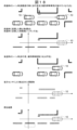
- FIG. 6A is an example of the processing according to this embodiment (when object type discrimination is included) (when a moving object such as a pedestrian is moving), and FIG. 6B is an example of the processing according to this embodiment (when object type discrimination is included).
- Another example (case where an object such as a utility pole is not detected) is shown. Since the moving object is not registered in the type map (FIG. 6A), and if the obstacle is not observed by the current rear sensor 14 and exists on the stored map, it can be determined that the rear sensor 14 has not detected it. Therefore, it is possible to distinguish whether the map is incorrect (it memorized a moving object that happened to be present) or whether the current rear sensor 14 is incorrect (not detected).
- FIG. 7 shows another example of the process (when the following vehicle disappears midway) using the known technology (when there is no object type discrimination)
- FIG. 8 shows the process according to the present embodiment (when there is object type discrimination) This shows a further example (when the following vehicle disappears on the way).
- FIG. 9 shows a further example of the process according to the known technology (when there is no object type discrimination) (when there is a following vehicle)
- FIG. 10 shows a further example of the process according to the present embodiment (when there is object type discrimination). Another example (when there is a following vehicle) is shown.
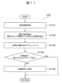
- the following vehicle detection section 112 determines (detects) the presence of a following vehicle from the information from the surrounding situation verification section 110.
- FIG. 11 shows a flowchart of the following vehicle detection unit 112 according to the first embodiment of the present invention.
- the flow shown in FIG. 11 is repeatedly executed (regularly) at a predetermined processing cycle.
- the following vehicle detection unit 112 acquires the matching result from the surrounding situation matching unit 110 in S1101.
- the difference in matching is extracted from the matching results obtained in S1101. Specifically, point groups (obstacles) that exist only in the current sensor information acquired from the rear sensor information acquisition unit 104 are extracted (see also the comparison results in FIG. 10).
- the point clouds (obstacles) extracted in S1102 are grouped based on the proximity of their positions. For example, points that are closer in distance than a predetermined position criterion can be grouped by regarding them as the same object.
- the following vehicle detection unit 112 determines that the obstacle (information) 108 stored in the memory 107 by the storage unit 106 does not exist among the stationary objects and is acquired from the rear sensor information acquisition unit 104 .
- the following vehicle Determine as.
- the following vehicle following control unit 113 follows the following vehicle by controlling the steering device, drive device, braking device, transmission device, etc. when the following vehicle is detected behind the own vehicle by the following vehicle detection unit 112. Performs following vehicle following control. Note that the following vehicle following control can be performed using a known following control method that is installed in, for example, an adaptive cruise control that follows a preceding vehicle.
- the surrounding situation verification unit 110 determines that the object is a moving object, and the reverse reproduction backward support control unit 111 , the reverse playback support is stopped based on the judgment of the surrounding situation comparison unit 110.
- the following vehicle detection unit 112 determines whether there is a following vehicle behind the own vehicle from the object, and if it is determined that there is a following vehicle behind the own vehicle, the following vehicle following control unit 113 controls the following vehicle detection unit Following vehicle following control is performed based on the determination in step 112.
- the passing space determination unit 114 detects (determines) a passing space on the rear side of the vehicle 10 in which the vehicle 10 can pass each other as a result of the verification by the surrounding situation verification unit 110 .
- FIG. 12 shows a flowchart of the passing space determination unit 114 according to the first embodiment of the present invention.
- the flow shown in FIG. 12 is repeatedly executed (regularly) at a predetermined processing cycle.
- the passing space determination unit 114 acquires the verification result from the surrounding situation verification unit 110 in S1201.
- the difference in matching is extracted from the matching results obtained in S1201. Specifically, the point group (obstacle) that exists only in the stored information (that is, the stationary object of the obstacle (information) 108) stored in the memory 107 by the storage unit 106 is extracted. Note that stored information outside the detection range of the current sensor used for verification is excluded.
- the point clouds (obstacles) extracted in S1202 are grouped based on the proximity of their positions. For example, points that are closer in distance than a predetermined position criterion can be grouped by regarding them as the same object.
- S1204 for the groups created in S1203, it is determined whether there is a group with a predetermined depth (4 m depth) or more behind the own vehicle. If there is a group, the process advances to S1205; if there is no group, S1205 is skipped and the process ends.
- the passing space determination unit 114 determines that the obstacle (information) 108 stored in the memory 107 by the storage unit 106 is present in a stationary object and that the current status acquired from the rear sensor information acquisition unit 104 is detected in the verification by the surrounding situation verification unit 110.
- the vehicle passes each other in a space where an object with a predetermined depth (depth of 4 m) or more exists behind the vehicle. Determine as space.
- the rear lateral movement support control unit 115 controls a steering device, a drive device, a braking device, a transmission device, etc. when a passing space is detected (determined) on the rear side of the own vehicle by the passing space determining unit 114. By doing so, the rear side movement support control is carried out to move to the passing space behind the own vehicle and assist in passing each other.
- the rearward and lateral movement support control can be performed using, for example, a known route generation/movement support control method that is installed in a system that automatically performs parallel parking.
- the current sensor information in other words, If there is an object that does not exist in the current obstacle information behind the vehicle obtained from the rear sensor 14, the surrounding situation verification unit 110 determines that there is a high possibility that the sensors 13 and 14 are malfunctioning, and performs reverse playback.
- the support control unit 111 stops the reverse playback support based on the judgment of the surrounding situation collation unit 110.
- the passing space determination unit 114 determines whether there is a passing space behind the vehicle from the object, and if it is determined that there is a passing space behind the vehicle, the rear lateral movement support control unit 115 Backward and lateral movement support control is performed based on the determination by the passing space determination unit 114.
- the following vehicle and surrounding obstacles are distinguished and memorized, so even if, for example, the following vehicle disappears midway, it can be compared when reversing. Can be carried out correctly.
- the second embodiment differs from the first embodiment in the object type discrimination method.
- the observation information of the front sensor 13 and the rear sensor 14 (sensor information consisting of point cloud data) is integrated to determine and store the object type, but in the second embodiment, the object type is determined based on the image. The object type is determined and stored from the observation information of the sensor that can be determined.
- FIG. 13 is a system configuration diagram of a driving support device 200 according to a second embodiment of the present invention.
- the driving support device 200 is a computer that controls the vehicle 10, and by executing a program stored in a storage medium, the driving assistance device 200 acquires a driving operation acquisition unit 101, a vehicle behavior acquisition unit 102, a front camera recognition information acquisition unit 203, and a rear sensor.
- the driving support device 200 of the second embodiment includes the front camera recognition information acquisition unit 203 and the obstacle discrimination unit instead of the front sensor information acquisition unit 103 and the obstacle discrimination unit 105 of the drive support device 100 of the first embodiment. 205.
- the driving support device 200 is connected to a front camera 23 (FIGS. 14A to 14D) mounted on the vehicle 10.
- the front camera 23 has a function as a front observation unit that observes the surrounding situation in front of the vehicle (self-vehicle) 10.
- the front camera 23 includes a sensor that can identify the type of object based on the image.
- the front camera 23 outputs image data including information that determines (recognizes) the object types of peripheral objects (obstacles) shown in the image to the driving support device 100.
- Types of objects that can be determined by the front camera 23 include pedestrians, bicycles, two-wheeled vehicles (motorcycles), vehicles (including parked vehicles), and the possibility of movement such as fences, signboards, poles, and pylons installed for construction purposes.
- moving objects and stationary objects such as signs, guardrails, walls, fences, signboards, poles, pylons, curbs, and car stops.
- the front camera recognition information acquisition unit 203 acquires observation information in front of the vehicle 10 (sensor information having image data that detects an obstacle in front of the vehicle 10) from the front camera 23.
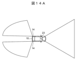
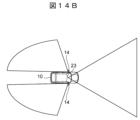
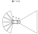
- FIG. 14A, B, C, and D show examples of mounting sensors 23 and 14 according to the second embodiment of the present invention.
- the front camera 23 and the rear sensor 14 are attached to the vehicle 10 so as to observe different directions in the surrounding situation of the vehicle 10. Further, the front camera 23 and the rear sensor 14 are configured using sensors with different characteristics.
- the front camera 23 is attached to the center of the front of the vehicle 10 (for example, the center of the inside of the windshield inside the vehicle) so as to face the front of the vehicle 10. .
- the mounting manner of the rear sensor 14 (FIGS. 14A to 14D) is basically the same as in the first embodiment. Note that the number, arrangement, etc. of the front camera 23 and the rear sensor 14 are not limited to the examples shown in FIGS. 14A to 14D.
- the obstacle determination unit 205 uses the sensor information acquired from the front camera recognition information acquisition unit 203 and the rear sensor information acquisition unit 104 to determine the object type of obstacles around the vehicle 10 (front and rear).
- the obstacle discrimination unit 205 discriminates at least stationary objects and other objects (moving objects, etc.) as object types.
- the obstacle discrimination unit 205 receives information from the rear sensor information acquisition unit 104 based on object type information (object type information determined by the front camera 23) of the sensor information acquired from the front camera recognition information acquisition unit 203. At least a stationary object is determined from the acquired sensor information (in other words, the detection result of the rear sensor 14).
- FIG. 15 shows a flowchart of the obstacle determination unit 205 according to the second embodiment of the present invention.
- the flow shown in FIG. 15 is repeatedly executed (regularly) at a predetermined processing cycle.
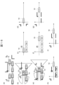
- FIG. 16 shows an example of obstacle discrimination processing by the obstacle discrimination unit 205 according to the second embodiment of the present invention.
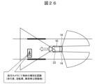
- FIG. 16(a) shows a scene in which a vehicle 10 is traveling from left to right on a narrow road, a pedestrian is present on the left side of the vehicle 10, and a plurality of vehicles stopped in parallel are present on the right side of the vehicle 10.
- FIG. 16(b) shows the detection status of the sensors 23 and 14 at the left position (time t- ⁇ t) of FIG. 16(a)
- FIG. 16(c) and FIG. A front sensor obstacle map and a rear sensor obstacle map created at the left position (time t- ⁇ t) are shown.
- FIG. 16(e) shows the detection status of the sensors 23 and 14 at the right position (time t) in FIG. 16(a)
- FIG. 16(f) and FIG. 16(g) show the detection status on the right side of FIG.
- 16(a) A front sensor obstacle map and a rear sensor obstacle map created at the position (time t) are shown.
- 16(h) and 16(i) show type maps created by comparing (superimposing) the front sensor obstacle map in FIG. 16(f) and the rear sensor obstacle map in FIG. 16(g). ing.
- hatched points indicate a point group that is determined as a moving object that may move, and black points indicate a point group that is determined as a stationary object.
- the obstacle determination unit 205 stores sensor information (image information and point cloud information that detects obstacles in front and behind the vehicle 10) acquired from the front camera recognition information acquisition unit 203 and the rear sensor information acquisition unit 104 in advance in memory.
- a front sensor obstacle map and a rear sensor obstacle map are created (updated) and stored in the memory (FIGS. 16(b), (c), and (d)).
- the obstacle determination unit 205 stores the previous (time t- ⁇ t, ⁇ t: processing cycle) front sensor obstacle map and rear sensor obstacle map stored in the memory as described above. (FIGS. 16(c) and (d)).
- vehicle behavior information is acquired from the vehicle behavior acquisition unit 102.
- the own vehicle position in the front sensor obstacle map and the rear sensor obstacle map is updated using the front sensor obstacle map and rear sensor obstacle map acquired in S1501 and the vehicle behavior information acquired in S1502. (Fig. 16(f), (g)).
- the object type information is registered at a position corresponding to the vicinity of the object recognition position Pf[p] of the front camera 23 in the front sensor obstacle map (of the previous time (time t- ⁇ t)) acquired in S1501.
- the obstacle point group Pr[q of the rear sensor 14 is acquired from the rear sensor information acquisition unit 104 (at this time (time t)), which is the sensor information (point cloud information that detected obstacles behind the vehicle 10). ] is superimposed on the rear sensor obstacle map (of the previous time (time t- ⁇ t)) acquired in S1501 (FIG. 16(g)).
- the obstacle discrimination unit 205 discriminates at least a stationary object from the detection results (point cloud) of the rear sensor 14 based on the object type information discriminated by the front camera 23.
- the obstacle discrimination unit 205 discriminates at least stationary objects and other obstacles (moving objects, etc.) among the obstacles around the own vehicle 10.
- FIG. 17 is an example of the process according to the present embodiment, in which there is a pedestrian on the left side of the host vehicle, a parallel stopped vehicle exists on the right side of the host vehicle, and the pedestrian disappears midway (during reverse support control). It shows the case.
- FIG. 18 shows another example of the process according to the present embodiment, in which there is a pedestrian on the left side of the own vehicle, a parallel stopped vehicle exists on the right side of the own vehicle, and the pedestrian and the parallel stopped vehicle (one vehicle) are on the way. This shows a case where a passing space occurs between vehicles stopped in parallel (during reverse support control).
- Pedestrians and vehicles stopped in parallel are registered in the type map with the attribute of a moving object, so it can be determined that there is a possibility that they will move during reverse support control.
- the reverse support control of the reverse reproduction backward support control section 111 or the movement support control of the rear and lateral movement support control section 115 can be appropriately performed.
- the obstacle discrimination unit 205 discriminates (detects) pedestrians and stopped vehicles on the left and right sides of the own vehicle 10 and stores them in the memory 107.
- the obstacle discrimination unit 205 discriminates (detects) pedestrians and stopped vehicles on the left and right sides of the own vehicle 10 and stores them in the memory 107.
- Similar control reverse playback support control of the reverse playback support control unit 111) , or movement support control of the rear-lateral movement support control unit 115).
- effect in addition to the same effects as the first embodiment, by determining the object type based on images, even if an object that may be moving is stationary, it can be determined as a moving object, and surrounding objects can be identified as moving objects. Since the detection (recognition) accuracy of is improved, comparisons can be made correctly when reversing.
- the third embodiment differs from the first and second embodiments in the reverse support control method.
- the route is recalculated (regenerated) to realize natural driving with less sense of discomfort.
- FIG. 19 is a system configuration diagram of a driving support device 300 according to a third embodiment of the present invention.
- the driving support device 300 is a computer that controls the vehicle 10, and acquires driving operation acquisition section 101, vehicle behavior acquisition section 102, front sensor information acquisition section 103, and rear sensor information by executing a program stored in a storage medium.
- the driving support device 300 of the third embodiment includes the storage section 306 and the reverse regeneration backward support control section 311 in place of the storage section 106 and the reverse regeneration backward support control section 111 of the driving support device 100 of the first embodiment. Be prepared.
- the driving support device 300 of the present embodiment recalculates (regenerates) the route for reversing in the above-mentioned case and realizes natural reversing with less discomfort.
- the storage unit 306 When storing the driving operation (information) acquired from the driving operation acquisition unit 101, the storage unit 306 stores the passing position point (waypoint) of the origin (for example, the center of the rear wheel axle) of the vehicle (self-vehicle) 10 when moving forward. , is stored in the memory 307 as a driving operation (information) 309. Note that it is preferable that the passing position points (waypoints) are stored at a constant distance.
- the storage unit 306 stores not only stationary objects but also moving objects as obstacles (information) 308 in the memory 307.
- the obstacle discrimination unit 105 discriminates (detects) moving objects on the left and right sides of the own vehicle, and the storage unit 306 also stores these moving objects on the left and right sides of the own vehicle in the memory 307 as obstacles (information) 308 .
- the reverse playback support control unit 311 performs feedback control on the reverse playback operation so that the waypoint is passed during the reverse playback support control. By following the waypoints in reverse order, it is possible to drive backwards by following the same route.
- the reverse reproduction backward support control section 311 includes a moving object movement determination section 316 and a reroute generation driving support control section 317.
- the moving object movement determination section 316 determines that a moving object (among the obstacles) has moved from the verification result of the surrounding situation verification section 110. Note that if the moving object movement determination section 316 cannot determine that the moving object has moved, the reverse regeneration backward support control section 311 supports backward travel by normal reverse regeneration.
- Reroute generation driving support control unit 317 When the moving object movement determination section 316 determines that the moving object has moved, the reroute generation driving support control section 317 generates a path for reversing the own vehicle and performs driving support control. At this time, the reroute generation driving support control unit 317 generates a route for reversing the own vehicle with the obstacles (information) 308 stored in the memory 307 by the storage unit 306 that are determined to have moved removed. By doing so, driving support control is implemented.
- FIG. 21 shows a flowchart of the reroute generation driving support control unit 317 according to the third embodiment of the present invention.
- the flow shown in FIG. 21 is repeatedly executed (regularly) at a predetermined processing cycle.
- the reroute generation driving support control unit 317 selects the waypoint closest to the host vehicle 10 in S2101.
- a preset determination area is set based on the waypoint and superimposed on the sensor obstacle map.
- the determination area is a predetermined area defined based on the origin of the vehicle (for example, a rectangular area defined by the length in the longitudinal direction of the vehicle and the width in the lateral direction of the vehicle).
- follow-up control to the route generated in S2106 (regenerated route) is performed by controlling the steering device, drive device, braking device, transmission device, etc.
- the reroute generation driving support control unit 317 first checks the presence or absence of moving objects around (within the determination area) based on the waypoint closest to the own vehicle 10 (S2101, S2102, S2103). If a moving object exists within the determination area, waypoints are searched in order of distance from the own vehicle 10 (S2104, S2102, S2103), and a waypoint where no moving object exists within the determination area is searched and set as the target position (target waypoint). Set (S2105). A route is generated toward the set waypoint and travel control (following control) is performed (S2106, S2107, S2108).
- the re-route generation driving support control unit 317 uses the storage unit 306 to store data in the memory 307 around the waypoint position (within the determination area) among the waypoint positions (waypoints) stored when the own vehicle moved forward.
- the target is a waypoint that is the closest (shortest) to the own vehicle 10 and is a waypoint where there are no obstacles (moving objects) determined to have moved among the obstacles (information) 308 that have moved. It is set as a passing point position (target waypoint), and a route is generated from the position of the own vehicle 10 toward the set target passing point position (target waypoint) to perform driving support control.
- the reroute generation driving support control unit 317 generates a route for reversing the own vehicle with the obstacles (information) 308 stored in the memory 307 by the storage unit 306 that are determined to have moved removed. to perform driving support control.
- the fourth embodiment differs from the first, second, and third embodiments in the following vehicle following control method.
- following vehicle following control is performed based on the observation information of the rear sensor 14, but in the fourth embodiment, communication with other vehicles is confirmed and transmission/reception is performed through communication between other vehicles. Based on this information, following vehicle following control is carried out.
- FIG. 22 is a system configuration diagram of a driving support device 400 according to a fourth embodiment of the present invention.
- the driving support device 400 is a computer that controls the vehicle 10, and acquires driving operation acquisition section 101, vehicle behavior acquisition section 102, front sensor information acquisition section 103, and rear sensor information by executing a program stored in a storage medium.
- the driving support device 400 of the fourth embodiment includes the following vehicle detection section 412 and the following vehicle following control section in place of the following vehicle detection section 112 and the following vehicle following control section 113 of the driving support device 100 of the first embodiment. 413, and further includes an other vehicle communication confirmation section 418 and a following vehicle information reception section 419.
- the following vehicle detection unit 412 determines (detects) the presence of a following vehicle from the information from the surrounding situation matching unit 110.
- the following vehicle detection section 412 outputs the detection result to the following vehicle following control section 413 and the other vehicle communication confirmation section 418.
- the other vehicle communication confirmation unit 418 confirms whether or not the vehicle (own vehicle) 10 can communicate with other vehicles in the vicinity.
- the other vehicle communication confirmation section 418 confirms whether communication with the following vehicle detected by the following vehicle detecting section 412 is possible.
- the following vehicle information receiving unit 419 is a following control transmitting/receiving unit that communicates with other cars when communication with other cars around the vehicle (self-vehicle) 10 is possible, and transmits and receives information necessary for following control to other cars. It has the function of The following vehicle information receiving section 419 communicates with the following vehicle when the other vehicle communication confirmation section 418 indicates that communication with the following vehicle is possible, and transmits and receives information necessary for following the vehicle in reverse.
- the following vehicle information receiving unit 419 receives information such as vehicle speed, acceleration/deceleration, steering (yaw angle), vehicle parameters, etc. from another vehicle (following vehicle) as information necessary for following control of the other vehicle (following vehicle). do.
- FIG. 23 is a diagram showing the communication connection relationship between the own vehicle and other vehicles.
- the other vehicle driving support device 500 includes a vehicle behavior acquisition unit 501, a vehicle behavior transmission unit 502, and another vehicle communication confirmation unit 503 in order to realize communication and information transmission/reception with the own vehicle driving support device 400.
- the vehicle behavior acquisition unit 501 acquires vehicle behavior (information) from various sensors mounted on the vehicle.
- the vehicle behavior acquisition unit 501 acquires behaviors (information) such as wheel speed (vehicle speed), acceleration/deceleration, steering (yaw angle), vehicle parameters, etc. of the vehicle, for example.
- the other vehicle communication confirmation unit 503 confirms whether or not the vehicle (here, the other vehicle) can communicate with other vehicles (here, the own vehicle) in the vicinity.
- the driving support device 400 of the own vehicle and the driving support device 500 of the other vehicle confirm whether or not they can communicate with each other through communication with the other vehicle communication confirmation unit 418 and the other vehicle communication confirmation unit 503.
- Vehicle behavior transmitter 502 communicates with other vehicles when the vehicle (here, other vehicles) can communicate with other vehicles (here, own vehicle) in the vicinity, and transmits information necessary for tracking control to other vehicles. It has a function as a follow-up control transmitting/receiving section that transmits and receives data.
- Vehicle behavior transmitting unit 502 communicates with the preceding vehicle (own vehicle 10) when communication with the preceding vehicle (own vehicle 10) is possible according to other vehicle communication confirmation unit 503, and communicates with the following vehicle (in this case, the other vehicle concerned). ) to send and receive information necessary for tracking and retreating.
- the vehicle behavior transmitting unit 502 transmits the information acquired by the vehicle behavior acquiring unit 501 to the following vehicle information receiving unit 419 of the driving support device 400 of the own vehicle as information necessary for following backward movement.
- the following vehicle following control unit 413 controls the steering device, drive device, braking device, transmission device, etc. to follow the following vehicle when the following vehicle is detected behind the own vehicle by the following vehicle detection unit 412. Performs following vehicle following control.
- the following vehicle information receiving section 419 receives information necessary for following the following vehicle in a backward direction
- the following vehicle following control section 413 implements following vehicle backward movement based on the received information.
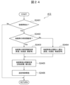
- FIG. 24 shows a flowchart of the following vehicle following control section 413 according to the fourth embodiment of the present invention.
- the flow shown in FIG. 24 is repeatedly executed (regularly) at a predetermined processing cycle.
- the following vehicle following control unit 413 determines in S2401 whether the following vehicle has been detected by the following vehicle detection unit 412, and if the following vehicle has been detected, the process proceeds to S2402.
- the following vehicle information receiving unit 419 determines whether there is information (vehicle information of the following vehicle) necessary for reversing to follow the following vehicle (whether or not it is being received). If there is vehicle information about the following vehicle, the process advances to S2403, and if there is no vehicle information about the following vehicle, the process advances to S2404.
- the following vehicle information receiving unit 419 acquires information necessary for following the following vehicle in reverse (vehicle information of the following vehicle), and the process proceeds to S2405.
- the vehicle information (speed, acceleration, lateral speed, etc.) of the following vehicle is calculated from the following vehicle detection information of the rear sensor 14 (that is, the sensor information acquired from the rear sensor information acquisition unit 104), and the process proceeds to S2405.
- the following vehicle detection information of the rear sensor 14 that is, the sensor information acquired from the rear sensor information acquisition unit 104
- the longitudinal distance (relative distance in the longitudinal direction or the traveling direction)
- the lateral position (lateral direction or perpendicular to the traveling direction)
- follow-up control for the following vehicle is performed based on the information acquired in S2403 or S2404 and S2405.
- the driving support devices 100, 200, 300, and 400 of this embodiment are a driving operation acquisition unit (101) that acquires the driving operation of the driver of the own vehicle;
- a forward observation information acquisition unit front sensor information acquisition unit 103, front camera recognition information
- forward observation information front sensor information
- front sensor 13, front camera 23 front observation unit
- rear observation information acquisition unit 104 that acquires rear observation information (rear sensor information) of a rear observation unit (rear sensor 14) that observes the surrounding situation behind the own vehicle;
- front observation information (front sensor information) of the front observation section and the rear observation information (rear sensor information) of the rear observation section are used to identify at least stationary objects among obstacles (around the vehicle).
- an obstacle discrimination unit (105, 205) for discriminating other objects; a storage unit (106, 306) that stores (in a memory (107, 307)) at least a stationary object among the obstacles determined by the obstacle determination unit and the driving operation acquired by the driving operation acquisition unit; a surrounding situation collation unit (110) that collates an obstacle behind the vehicle obtained by the rear observation unit and a stationary object stored (in memory) by the storage unit when the vehicle backs up on the forward path; a reverse regeneration backward support control unit (111, 311) that supports backward driving by reproducing the driving operation stored in the storage unit (memory) in the memory when the own vehicle is moving forward; has The reverse playback support control unit (111, 311) determines whether to implement reverse playback support according to the verification result obtained by the surrounding situation verification unit (110).
- the driving support devices 100, 200, 300, and 400 of this embodiment store the driver's driving operation and surrounding obstacle information when moving forward.
- information from the front sensor 13 (or front camera 23) and rear sensor 14 is integrated to determine the object type (stationary object, moving object) and store it.
- the surrounding obstacles detected by the rear sensor 14 are compared with the stored surrounding obstacles, and based on the comparison result, it is determined whether to perform the backward support based on the stored driving operation.
- the object type is determined by comparing the detection positions of both the front sensor 13 and the rear sensor 14. For example, a wall is detected by both the front sensor 13 and the rear sensor 14, and can be determined as a stationary object. When a pedestrian moves, the detection positions differ between the front sensor 13 and the rear sensor 14, so that the pedestrian can be identified as a moving object. Since the following vehicle is not detected by the front sensor 13, it can be determined as a moving object (see the first embodiment, FIG. 25, etc.).
- the object type is discriminated based on information (pedestrian, bicycle, vehicle, etc.) recognized by the front camera 23.
- information pedestrians, bicycles, vehicles, etc.
- pedestrians, bicycles, vehicles, etc. can be identified as moving objects by (images of) the front camera 23 (see the second embodiment, FIG. 26, etc.). In this case, even if a pedestrian, bicycle, vehicle, etc. is stationary, it can be determined as a moving object.
- moving objects such as stopped vehicles and pedestrians are stored separately, it is recognized that moving objects such as stopped vehicles and pedestrians that were present when moving forward are moved and lost when reversing. be able to.
- an area stored as an immovable obstacle (stationary object) cannot currently be detected, it can be recognized that the vehicle cannot be detected due to a sensor malfunction or the like when reversing.
- the following vehicle and surrounding obstacles are distinguished and memorized, so even if, for example, the following vehicle disappears midway, it can be compared when reversing. Can be carried out correctly.
- safe and convenient driving support devices 100, 200, 300, and 400 can be provided in situations where reverse regeneration cannot be performed, such as when passing each other on a narrow road.
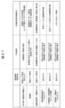
- FIG. 27 shows an example of an application scene and an example of operation of the driving support device according to this embodiment.
- scenes in which pedestrians and bicycles move scenes in which there is a following vehicle (when the following vehicle disappears midway), scenes in which a vehicle stopped in parallel disappears after passing along the side, and scenes in a construction area or construction site.
- Reverse playback cannot be performed in scenes where a fence has been moved or where a bicycle or two-wheeled vehicle left on the roadside has disappeared.
- reverse playback starts at the beginning of backing up.
- control is performed as if the bicycle or two-wheeled vehicle were not there.
- reverse playback is stopped when reversing starts, alerting the driver, and manual switching is performed.
- the number of control patterns that can be applied in each scene increases compared to the known technology, thereby improving convenience for the driver.
- the driving support device of this embodiment is a driving operation acquisition unit (101) that acquires the driving operation of the driver of the own vehicle;
- a first observation information acquisition unit front sensor information acquisition unit 103, Front camera recognition information acquisition unit 203);
- a second observation information acquisition unit (rear sensor information acquisition unit 104)
- the first observation information (sensor information) of the first observation section and the second observation information (sensor information) of the second observation section are used to detect obstacles (around the vehicle).
- At least an obstacle discrimination unit (105, 205) that discriminates between stationary objects and other objects; a storage unit (106, 306) that stores (in a memory (107, 307)) at least a stationary object among the obstacles determined by the obstacle determination unit and the driving operation acquired by the driving operation acquisition unit; When the own vehicle travels the route traveled again, the obstacles obtained from the first observation section or the second observation section are compared with the obstacles (stationary objects) stored (in the memory) by the storage section.
- the driving support control unit (reverse regeneration backward support control unit 111, 311 ) and,
- the driving support control unit (reverse regeneration backing support control unit 111, 311) can be configured as a device that determines whether to implement driving support according to the verification result obtained by the surrounding situation verification unit (110). .
- the driving support device of the embodiment described above is applicable to a reversing support system for automobiles, an automatic reversing support system for self-driving cars, a reversing driving support system for forklifts, etc.
- the present invention is not limited to the embodiments described above, and includes various modifications.
- the above-described embodiments have been described in detail to explain the present invention in an easy-to-understand manner, and the present invention is not necessarily limited to having all the configurations described.
- each of the above-mentioned configurations, functions, processing units, processing means, etc. may be partially or entirely realized in hardware by, for example, designing an integrated circuit.
- each of the above configurations, functions, etc. may be realized by software by having a processor interpret and execute a program for realizing each function.
- Information such as programs, tables, files, etc. that implement each function can be stored in a memory, a recording device such as a hard disk, an SSD (Solid State Drive), or a recording medium such as an IC card, SD card, or DVD.
- control lines and information lines shown are those considered necessary for explanation, and do not necessarily show all control lines and information lines necessary for implementation. In reality, almost all configurations can be considered interconnected.
Landscapes
- Engineering & Computer Science (AREA)
- Automation & Control Theory (AREA)
- Transportation (AREA)
- Mechanical Engineering (AREA)
- Physics & Mathematics (AREA)
- General Physics & Mathematics (AREA)
- Human Computer Interaction (AREA)
- Life Sciences & Earth Sciences (AREA)
- Atmospheric Sciences (AREA)
- Traffic Control Systems (AREA)
Abstract
Description
まず、図1~図12を参照して、本発明の運転支援装置の第1実施形態を説明する。
図1は、本発明の第1実施形態に係る運転支援装置100のシステム構成図である。運転支援装置100は、車両(自車)10に搭載されており、車両10が備える各機能部を電子的に制御することによって、ドライバの運転操作を支援する装置である。本実施形態の運転支援装置100は、例えば狭路でのすれ違い等の際に、車両10の前進時に記憶した情報から、車両10の後退走行(すなわち、車両10の後退時の運転操作)を支援(後退支援制御)する装置である。
運転操作取得部101は、車両10に搭載された各種センサから、車両10のドライバの運転操作(情報)を取得する。運転操作取得部101は、例えば、アクセル操作、ブレーキ操作、ステアリング操作(操舵角)、シフトレバー操作等といった、車両10の加減速、操舵、シフト位置等に関するドライバの運転操作(情報)を取得する。
車両挙動取得部102は、車両10に搭載された各種センサから、車両10の挙動(情報)を取得する。車両挙動取得部102は、例えば、車両10の車輪速(車速)、加速度、横速度(ヨー角)等の挙動(情報)を取得する。
運転支援装置100は、車両10に搭載された前方センサ13(図2A~D)と接続されている。前方センサ13は、車両(自車)10の前方の周辺状況を観測する前方観測部としての機能を有する。前方センサ13は、例えば、画像を用いて周辺物体との距離を計測するカメラ、ミリ波やレーザー光を用いて周辺物体との距離を計測するレーダ、超音波を用いて周辺物体との距離を計測するソナー等を用いることができる。前方センサ13は、周辺物体の境界部分の座標を表す点群データを運転支援装置100に出力する。
運転支援装置100は、車両10に搭載された後方センサ14(図2A~D)と接続されている。後方センサ14は、車両(自車)10の後方の周辺状況を観測する後方観測部としての機能を有する。後方センサ14は、例えば、画像を用いて周辺物体との距離を計測するカメラ、ミリ波やレーザー光を用いて周辺物体との距離を計測するレーダ、超音波を用いて周辺物体との距離を計測するソナー等を用いることができる。後方センサ14は、周辺物体の境界部分の座標を表す点群データを運転支援装置100に出力する。
図2A、B、C、Dは、本発明の第1実施形態に係るセンサ13、14の搭載例を示している。上記したように、本実施形態において、前方センサ13と後方センサ14は、車両10の周辺状況において異なる方向を観測するように車両10に取り付けられている。また、前方センサ13と後方センサ14は、カメラ、レーダ、ソナー等の同じ特性のセンサを用いて構成されている。
障害物判別部105は、前方センサ情報取得部103と後方センサ情報取得部104から取得したセンサ情報を用いて(統合して)、車両10の周辺(前方、後方)の障害物の物体種別を判別する。障害物判別部105は、物体種別として、少なくとも静止物とそれ以外(移動物等)を判別する。
記憶部106は、障害物判別部105から取得した障害物(情報)(障害物判別部105により判別した障害物の物体種別(情報)を含む)と、運転操作取得部101から取得した運転操作(情報)を、障害物(情報)108と、運転操作(情報)109として、メモリ107に記憶する。記憶部106は、障害物判別部105により判別された障害物のうち少なくとも静止物を、障害物(情報)108としてメモリ107に記憶する。
周辺状況照合部110は、車両10が前進した経路を後退する際に実施される。より詳しくは、前進する車両10のドライバから後退支援制御の実施の要求があった際に実施される。ドライバからの後退支援制御の実施の要求は、例えば車両10に設けられたスイッチ入力やタッチパネル入力の操作、音声の認識、シフトレバーの後退への切り替え操作等を介して認識することができる。
逆再生後退支援制御部111は、車両10が前進した経路を後退する際に実施される。逆再生後退支援制御部111は、車両10の前進時に記憶部106によりメモリ107に記憶した運転操作(情報)109を取得してその逆再生により後退走行を支援(後退支援を実施)する。すなわち、逆再生後退支援制御部111は、車両10の前進時に記憶部106によりメモリ107に記憶した運転操作(情報)109の逆再生となるように、操舵装置、駆動装置、制動装置、変速装置等を制御することにより後退走行を支援する。
後続車検出部112は、周辺状況照合部110の情報から後続車の存在を判定(検出)する。
後続車追従制御部113は、後続車検出部112により自車後方に後続車が検出されている際に、操舵装置、駆動装置、制動装置、変速装置等を制御することにより後続車に追従する後続車追従制御を実施する。なお、後続車追従制御は、例えば先行車を追従するアダプティブクルーズコントロール等に搭載されている、公知の追従制御手法を用いて実施することができる。
すれ違い空間判定部114は、周辺状況照合部110の照合の結果、車両10がすれ違い可能な車両10の後側方のすれ違い空間を検出(判定)する。
後側方移動支援制御部115は、すれ違い空間判定部114により自車後側方にすれ違い空間が検出(判定)されている際に、操舵装置、駆動装置、制動装置、変速装置等を制御することにより自車後側方のすれ違い空間へ移動してすれ違いを支援する後側方移動支援制御を実施する。なお、後側方移動支援制御は、例えば縦列停車を自動で実施するシステムに搭載されている、公知の経路生成・移動支援制御手法を用いて実施することができる。
本実施形態によれば、停車車両や歩行者等の移動する物体を区別して記憶するため、前進時に存在した停車車両や歩行者等の移動する物体が後退時に移動して紛失したことを認知することができる。同様に、移動しない障害物(静止物)として記憶した領域が現在検出できない場合は、後退時にセンサの不具合等で検出できない状況であることを認知することができる。
次に、図13~図18を参照して、本発明の運転支援装置の第2実施形態を説明する。第2実施形態は、第1実施形態に対して物体種別判別方法が異なる。第1実施形態では、前方センサ13及び後方センサ14の観測情報(点群データからなるセンサ情報)を統合して物体種別を判別して記憶するが、第2実施形態では、画像による物体種別が判別可能なセンサの観測情報から物体種別を判別して記憶する。
図13は、本発明の第2実施形態に係る運転支援装置200のシステム構成図である。
運転支援装置200は、車両10に搭載された前方カメラ23(図14A~D)と接続されている。前方カメラ23は、車両(自車)10の前方の周辺状況を観測する前方観測部としての機能を有する。前方カメラ23は、画像による物体種別が判別可能なセンサにより構成されている。前方カメラ23は、画像に映る周辺物体(障害物)の物体種別を判別(認識)した情報を含む画像データを運転支援装置100に出力する。
図14A、B、C、Dは、本発明の第2実施形態に係るセンサ23、14の搭載例を示している。上記したように、本実施形態において、前方カメラ23と後方センサ14は、車両10の周辺状況において異なる方向を観測するように車両10に取り付けられている。また、前方カメラ23と後方センサ14は、異なる特性のセンサを用いて構成されている。
障害物判別部205は、前方カメラ認識情報取得部203と後方センサ情報取得部104から取得したセンサ情報を用いて、車両10の周辺(前方、後方)の障害物の物体種別を判別する。障害物判別部205は、物体種別として、少なくとも静止物とそれ以外(移動物等)を判別する。
本実施形態によれば、第1実施形態と同様の作用効果に加えて、画像による物体種別の判別により、移動する可能性がある物体が静止している場合でも移動物として判別でき、周囲物体の検出(認識)精度が向上するため、後退時の比較を正しく実施することができる。
次に、図19~図21を参照して、本発明の運転支援装置の第3実施形態を説明する。第3実施形態は、第1、第2実施形態に対して後退支援制御方法が異なる。第3実施形態では、単純な逆再生を実施するとドライバに違和感を与える可能性がある場合に経路を再計算(再生成)して違和感の少ない自然な走行を実現する。
図19は、本発明の第3実施形態に係る運転支援装置300のシステム構成図である。
記憶部306は、運転操作取得部101から取得した運転操作(情報)を記憶する際に、前進時の車両(自車)10の原点(例えば後輪車軸中心)の通過位置点(waypoint)を、運転操作(情報)309として、メモリ307に記憶する。なお、通過位置点(waypoint)は一定距離で記憶することが好ましい。
逆再生後退支援制御部311は、逆再生後退支援制御時に、waypointを通過するように逆再生操作にフィードバック制御を実施する。waypointを逆順にたどることで、同じ経路をたどる後退走行を実現する。逆再生後退支援制御部311は、移動物移動判定部316と、再経路生成走行支援制御部317と、を有する。
移動物移動判定部316は、周辺状況照合部110の照合結果から(障害物のうち)移動物が移動したことを判定する。なお、移動物移動判定部316により移動物が移動したことを判定できない場合、逆再生後退支援制御部311は、通常の逆再生により後退走行を支援する。
再経路生成走行支援制御部317は、移動物移動判定部316により移動物が移動したと判定した場合に、自車後退時の経路を生成して走行支援制御を実施する。このとき、再経路生成走行支援制御部317は、記憶部306によりメモリ307に記憶した障害物(情報)308のうち移動したと判定した障害物を除去した状態で自車後退時の経路を生成することによって走行支援制御を実施する。
本実施形態によれば、第1、第2実施形態と同様の作用効果に加えて、単純な逆再生を実施するとドライバに違和感を与える可能性がある場合でも違和感の少ない自然な走行を実現することができる。
次に、図22~図24を参照して、本発明の運転支援装置の第4実施形態を説明する。第4実施形態は、第1、第2、第3実施形態に対して後続車追従制御方法が異なる。第1、第2、第3実施形態では、後方センサ14の観測情報を基に後続車追従制御を実施するが、第4実施形態では、他車通信確認を実施した上で他車間通信により送受信した情報を基に後続車追従制御を実施する。
図22は、本発明の第4実施形態に係る運転支援装置400のシステム構成図である。
後続車検出部412は、第1実施形態で説明したように、周辺状況照合部110の情報から後続車の存在を判定(検出)する。後続車検出部412は、検出結果を後続車追従制御部413及び他車通信確認部418に出力する。
他車通信確認部418は、車両(自車)10の周辺の他車との通信可否を確認する。他車通信確認部418は、後続車検出部412により後続車が検出された場合、後続車検出部412により検出された後続車との通信可否を確認する。
後続車情報受信部419は、車両(自車)10の周辺の他車との通信可の場合に他車との通信を行い他車への追従制御に必要な情報を送受信する追従制御送受信部としての機能を有する。後続車情報受信部419は、他車通信確認部418により後続車との通信可の場合に、後続車との通信を行い、後続車への追従後退に必要な情報を送受信する。後続車情報受信部419は、他車(後続車)への追従制御に必要な情報として、車速、加減速、操舵(ヨー角)、車両パラメータ等の情報を、他車(後続車)から受信する。
図23は、自車と他車との通信接続関係図である。他車の運転支援装置500は、自車の運転支援装置400との通信並びに情報送受信を実現するため、車両挙動取得部501、車両挙動送信部502、及び他車通信確認部503を備える。
車両挙動取得部501は、車両に搭載された各種センサから、車両の挙動(情報)を取得する。車両挙動取得部501は、例えば、車両の車輪速(車速)、加減速、操舵(ヨー角)、車両パラメータ等の挙動(情報)を取得する。
他車通信確認部503は、車両(ここでは他車)の周辺の他車(ここでは自車)との通信可否を確認する。自車の運転支援装置400と他車の運転支援装置500は、他車通信確認部418と他車通信確認部503との通信により、相互の通信可否を確認する。
車両挙動送信部502は、車両(ここでは他車)の周辺の他車(ここでは自車)との通信可の場合に他車との通信を行い他車への追従制御に必要な情報を送受信する追従制御送受信部としての機能を有する。車両挙動送信部502は、他車通信確認部503により先行車(自車10)との通信可の場合に、先行車(自車10)との通信を行い、後続車(ここでは当該他車)への追従後退に必要な情報を送受信する。車両挙動送信部502は、追従後退に必要な情報として、車両挙動取得部501により取得した情報を、自車の運転支援装置400の後続車情報受信部419に送信する。
後続車追従制御部413は、後続車検出部412により自車後方に後続車が検出されている際に、操舵装置、駆動装置、制動装置、変速装置等を制御することにより後続車に追従する後続車追従制御を実施する。後続車追従制御部413は、後続車情報受信部419により後続車への追従後退に必要な情報を受信している際に、受信した情報に基づき後続車への追従後退を実施する。
本実施形態によれば、第1、第2、第3実施形態と同様の作用効果に加えて、後続車から後続車への追従後退に必要な情報を受信可能な際に、その受信情報に基づき後続車への追従後退を実施できるため、後退時の走行制御をより正確に実施することができる。
以上で説明したように、本実施形態の運転支援装置100、200、300、400は、
自車のドライバの運転操作を取得する運転操作取得部(101)と、
自車前方の周辺状況を観測する前方観測部(前方センサ13、前方カメラ23)の前方観測情報(前方センサ情報)を取得する前方観測情報取得部(前方センサ情報取得部103、前方カメラ認識情報取得部203)と、
自車後方の周辺状況を観測する後方観測部(後方センサ14)の後方観測情報(後方センサ情報)を取得する後方観測情報取得部(後方センサ情報取得部104)と、
自車前進時に前記前方観測部の前方観測情報(前方センサ情報)と前記後方観測部の後方観測情報(後方センサ情報)を用いて(自車の周辺の)障害物のうち少なくとも静止物とそれ以外を判別する障害物判別部(105、205)と、
前記障害物判別部により判別された障害物のうち少なくとも静止物と前記運転操作取得部により取得された運転操作を(メモリ(107、307)に)記憶する記憶部(106、306)と、
自車が前進した経路を後退する際に前記後方観測部より得られた自車後方の障害物と前記記憶部により(メモリに)記憶した静止物を照合する周辺状況照合部(110)と、
自車が前進した経路を後退する際に、自車前進時に前記記憶部により(メモリに)記憶した運転操作の逆再生により後退走行を支援する逆再生後退支援制御部(111、311)と、を有し、
前記逆再生後退支援制御部(111、311)は、前記周辺状況照合部(110)により得られる照合の結果に応じて逆再生後退支援の実施有無を決定する。
自車のドライバの運転操作を取得する運転操作取得部(101)と、
自車の周辺状況を観測する第一の観測部(前方センサ13、前方カメラ23)の第一の観測情報(センサ情報)を取得する第一の観測情報取得部(前方センサ情報取得部103、前方カメラ認識情報取得部203)と、
自車の周辺状況において前記第一の観測部(前方センサ13、前方カメラ23)とは異なる方向を観測する第二の観測部(後方センサ14)の第二の観測情報(センサ情報)を取得する第二の観測情報取得部(後方センサ情報取得部104)と、
自車走行時に前記第一の観測部の第一の観測情報(センサ情報)と前記第二の観測部の第二の観測情報(センサ情報)を用いて(自車の周辺の)障害物のうち少なくとも静止物とそれ以外を判別する障害物判別部(105、205)と、
前記障害物判別部により判別された障害物のうち少なくとも静止物と前記運転操作取得部により取得された運転操作を(メモリ(107、307)に)記憶する記憶部(106、306)と、
自車が走行した経路を再度走行する際に前記第一の観測部もしくは前記第二の観測部より得られた障害物と前記記憶部により(メモリに)記憶した障害物(静止物)を照合する周辺状況照合部(110)と、
自車が走行した経路を再度走行する際に、自車走行時に前記記憶部により(メモリに)記憶した運転操作に基づき運転走行を支援する走行支援制御部(逆再生後退支援制御部111、311)と、を有し、
前記走行支援制御部(逆再生後退支援制御部111、311)は、前記周辺状況照合部(110)により得られる照合の結果に応じて走行支援の実施有無を決定する装置として構成することができる。
11 後続車
13 前方センサ(前方観測部、第一の観測部)
14 後方センサ(後方観測部、第二の観測部)
23 前方カメラ(前方観測部、第一の観測部)
100 運転支援装置(第1実施形態)
101 運転操作取得部
102 車両挙動取得部
103 前方センサ情報取得部(前方観測情報取得部、第一の観測情報取得部)
104 後方センサ情報取得部(後方観測情報取得部、第二の観測情報取得部)
105 障害物判別部
106 記憶部
107 メモリ
108 障害物
109 運転操作
110 周辺状況照合部
111 逆再生後退支援制御部(走行支援制御部)
112 後続車検出部
113 後続車追従制御部
114 すれ違い空間判定部
115 後側方移動支援制御部
200 運転支援装置(第2実施形態)
203 前方カメラ認識情報取得部(前方観測情報取得部、第一の観測情報取得部)
205 障害物判別部
300 運転支援装置(第3実施形態)
306 記憶部
307 メモリ
308 障害物
309 運転操作
311 逆再生後退支援制御部(走行支援制御部)
316 移動物移動判定部
317 再経路生成走行支援制御部
400 運転支援装置(第4実施形態)
412 後続車検出部
413 後続車追従制御部
418 他車通信確認部
419 後続車情報受信部(追従制御送受信部)
500 運転支援装置(他車:後続車)
501 車両挙動取得部
502 車両挙動送信部(追従制御送受信部)
503 他車通信確認部
Claims (15)
- 自車のドライバの運転操作を取得する運転操作取得部と、
自車の周辺状況を観測する第一の観測部の第一の観測情報を取得する第一の観測情報取得部と、
自車の周辺状況において前記第一の観測部とは異なる方向を観測する第二の観測部の第二の観測情報を取得する第二の観測情報取得部と、
自車走行時に前記第一の観測部の第一の観測情報と前記第二の観測部の第二の観測情報を用いて障害物のうち少なくとも静止物とそれ以外を判別する障害物判別部と、
前記障害物判別部により判別された障害物のうち少なくとも静止物と前記運転操作取得部により取得された運転操作を記憶する記憶部と、
自車が走行した経路を再度走行する際に前記第一の観測部もしくは前記第二の観測部より得られた障害物と前記記憶部により記憶した障害物を照合する周辺状況照合部と、
自車が走行した経路を再度走行する際に、自車走行時に前記記憶部により記憶した運転操作に基づき運転走行を支援する走行支援制御部と、を有し、
前記走行支援制御部は、前記周辺状況照合部により得られる照合の結果に応じて走行支援の実施有無を決定することを特徴とする、運転支援装置。 - 自車のドライバの運転操作を取得する運転操作取得部と、
自車前方の周辺状況を観測する前方観測部の前方観測情報を取得する前方観測情報取得部と、
自車後方の周辺状況を観測する後方観測部の後方観測情報を取得する後方観測情報取得部と、
自車前進時に前記前方観測部の前方観測情報と前記後方観測部の後方観測情報を用いて障害物のうち少なくとも静止物とそれ以外を判別する障害物判別部と、
前記障害物判別部により判別された障害物のうち少なくとも静止物と前記運転操作取得部により取得された運転操作を記憶する記憶部と、
自車が前進した経路を後退する際に前記後方観測部より得られた自車後方の障害物と前記記憶部により記憶した静止物を照合する周辺状況照合部と、
自車が前進した経路を後退する際に、自車前進時に前記記憶部により記憶した運転操作の逆再生により後退走行を支援する逆再生後退支援制御部と、を有し、
前記逆再生後退支援制御部は、前記周辺状況照合部により得られる照合の結果に応じて逆再生後退支援の実施有無を決定することを特徴とする、運転支援装置。 - 請求項2に記載の運転支援装置において、
前記前方観測部と前記後方観測部は同じ特性のセンサを用いて構成されており、
前記障害物判別部は、前記前方観測部と前記後方観測部の双方にて検出された同一の障害物を静止物として判別し、
前記周辺状況照合部は、前記記憶部により記憶された静止物と前記後方観測部より得られた現在の自車後方の障害物の照合において、前記記憶部により記憶された静止物に存在せず、前記後方観測部より得られた現在の自車後方の障害物に存在する物体を移動物として判断し、
前記逆再生後退支援制御部は、前記移動物が照合時に含まれる場合には逆再生後退支援を実施しないことを特徴とする、運転支援装置。 - 請求項3に記載の運転支援装置において、
前記周辺状況照合部は、前記記憶部により記憶された静止物と前記後方観測部より得られた現在の自車後方の障害物の照合において、前記記憶部により記憶された静止物に存在し、前記後方観測部より得られた現在の自車後方の障害物に存在しない物体は、センサの不具合の可能性が高いと判断し、
前記逆再生後退支援制御部は、照合時に前記センサの不具合の可能性が高いと判断した場合には逆再生後退支援を実施せず、ドライバに注意喚起することを特徴とする、運転支援装置。 - 請求項3に記載の運転支援装置において、
前記周辺状況照合部の情報から後続車を検出する後続車検出部と、
前記後続車検出部により後続車が検出されている際に後続車に追従する後続車追従制御部と、を有することを特徴とする、運転支援装置。 - 請求項3に記載の運転支援装置において、
前記周辺状況照合部の照合の結果、自車がすれ違い可能な自車後側方のすれ違い空間を検出するすれ違い空間判定部と、
前記すれ違い空間判定部により検出した自車後側方のすれ違い空間へ移動してすれ違いを支援する後側方移動支援制御部と、を有することを特徴とする、運転支援装置。 - 請求項2に記載の運転支援装置において、
前記前方観測部は、画像による物体の種別が判別可能なセンサにより構成され、
前記障害物判別部は、前記前方観測部により判別された物体の種別情報に基づき前記後方観測部の検出結果から静止物を判別し、
前記周辺状況照合部は、前記記憶部により記憶された静止物と前記後方観測部より得られた現在の自車後方の障害物の照合において、前記記憶部により記憶された静止物に存在せず、前記後方観測部より得られた現在の自車後方の障害物に存在する物体を移動物として判断し、
前記逆再生後退支援制御部は、前記移動物が照合時に含まれる場合には逆再生後退支援を実施しないことを特徴とする、運転支援装置。 - 請求項7に記載の運転支援装置において、
前記周辺状況照合部は、前記記憶部により記憶された静止物と前記後方観測部より得られた現在の自車後方の障害物の照合において、前記記憶部により記憶された静止物に存在し、前記後方観測部より得られた現在の自車後方の障害物に存在しない物体は、センサの不具合の可能性が高いと判断し、
前記逆再生後退支援制御部は、照合時に前記センサの不具合の可能性が高いと判断した場合には逆再生後退支援を実施せず、ドライバに注意喚起することを特徴とする、運転支援装置。 - 請求項7に記載の運転支援装置において、
前記障害物判別部は、左右の停車車両もしくは工事領域を検出し、
前記記憶部は、前記障害物判別部により検出した左右の停車車両もしくは工事領域を記憶し、
前記周辺状況照合部の照合の結果、自車がすれ違い可能な自車後側方のすれ違い空間を検出するすれ違い空間判定部と、
前記すれ違い空間判定部により検出した自車後側方のすれ違い空間へ移動してすれ違いを支援する後側方移動支援制御部と、を有することを特徴とする、運転支援装置。 - 請求項3に記載の運転支援装置において、
前記周辺状況照合部の照合結果から移動物が移動したことを判定する移動物移動判定部と、
前記移動物移動判定部により移動物が移動したと判定した場合に、前記記憶部により記憶した障害物情報のうち移動したと判定した障害物を除去した状態で自車の経路を生成して走行支援制御を行う再経路生成走行支援制御部と、を有することを特徴とする、運転支援装置。 - 請求項7に記載の運転支援装置において、
前記障害物判別部は、左右の移動する物体を検出し、
前記記憶部は、前記障害物判別部により検出した左右の移動する物体を記憶し、
前記周辺状況照合部の照合結果から移動物が移動したことを判定する移動物移動判定部と、
前記移動物移動判定部により移動物が移動したと判定した場合に、前記記憶部により記憶した障害物情報のうち移動したと判定した障害物を除去した状態で自車の経路を生成して走行支援制御を行う再経路生成走行支援制御部と、を有することを特徴とする、運転支援装置。 - 請求項5に記載の運転支援装置において、
他車との通信可否を確認する他車通信確認部と、
他車との通信可の場合に他車との通信を行い他車への追従制御に必要な情報を送受信する追従制御送受信部と、を有し、
前記後続車検出部により後続車が検出された場合、
前記他車通信確認部は、後続車との通信可否を確認し、
後続車との通信可の場合、
前記追従制御送受信部は、後続車への追従後退に必要な情報を送受信し、
前記後続車追従制御部は、前記情報に基づき後続車への追従制御を実施することを特徴とする、運転支援装置。 - 請求項5に記載の運転支援装置において、
前記後続車検出部は、前記記憶部により記憶された静止物と前記後方観測部より得られた現在の自車後方の障害物の照合において、前記記憶部により記憶された静止物に存在せず、前記後方観測部より得られた現在の自車後方の障害物に存在する物体のうち、自車後方の所定幅以上の物体を後続車として判定することを特徴とする、運転支援装置。 - 請求項6に記載の運転支援装置において、
前記すれ違い空間判定部は、前記記憶部により記憶された静止物と前記後方観測部より得られた現在の自車後方の障害物の照合において、前記記憶部により記憶された静止物に存在し、前記後方観測部より得られた現在の自車後方の障害物に存在しない物体のうち、自車後方の所定奥行以上の物体が存在する空間をすれ違い空間として判定することを特徴とする、運転支援装置。 - 請求項10に記載の運転支援装置において、
前記再経路生成走行支援制御部は、自車前進時に記憶した通過点位置のうち、通過点位置の周囲に前記記憶部により記憶した障害物情報のうち移動したと判定した障害物が存在しない通過点位置であって自車から最も近い通過点位置を目標通過点位置として設定し、自車の位置から設定した目標通過点位置に向かって経路を生成して走行支援制御を行うことを特徴とする、運転支援装置。
Priority Applications (3)
| Application Number | Priority Date | Filing Date | Title |
|---|---|---|---|
| DE112023000653.9T DE112023000653T5 (de) | 2022-05-11 | 2023-03-15 | Fahrassistenzvorrichtung |
| CN202380027973.1A CN118891181A (zh) | 2022-05-11 | 2023-03-15 | 驾驶辅助装置 |
| US18/847,459 US20250242800A1 (en) | 2022-05-11 | 2023-03-15 | Driving assistance device |
Applications Claiming Priority (2)
| Application Number | Priority Date | Filing Date | Title |
|---|---|---|---|
| JP2022-078071 | 2022-05-11 | ||
| JP2022078071A JP7859869B2 (ja) | 2022-05-11 | 2022-05-11 | 運転支援装置 |
Publications (1)
| Publication Number | Publication Date |
|---|---|
| WO2023218755A1 true WO2023218755A1 (ja) | 2023-11-16 |
Family
ID=88729990
Family Applications (1)
| Application Number | Title | Priority Date | Filing Date |
|---|---|---|---|
| PCT/JP2023/010136 Ceased WO2023218755A1 (ja) | 2022-05-11 | 2023-03-15 | 運転支援装置 |
Country Status (5)
| Country | Link |
|---|---|
| US (1) | US20250242800A1 (ja) |
| JP (1) | JP7859869B2 (ja) |
| CN (1) | CN118891181A (ja) |
| DE (1) | DE112023000653T5 (ja) |
| WO (1) | WO2023218755A1 (ja) |
Families Citing this family (1)
| Publication number | Priority date | Publication date | Assignee | Title |
|---|---|---|---|---|
| US20240353230A1 (en) * | 2023-04-19 | 2024-10-24 | Apple Inc. | Probe based routing directions |
Citations (4)
| Publication number | Priority date | Publication date | Assignee | Title |
|---|---|---|---|---|
| JP2001043498A (ja) * | 1999-07-28 | 2001-02-16 | Honda Motor Co Ltd | 隊列走行装置 |
| JP2008302711A (ja) * | 2007-06-05 | 2008-12-18 | Denso Corp | 発進支援装置 |
| JP2012173843A (ja) * | 2011-02-18 | 2012-09-10 | Nissan Motor Co Ltd | 走行経路生成装置、及び走行経路生成方法 |
| JP2016085484A (ja) * | 2014-10-22 | 2016-05-19 | 株式会社デンソー | 車載用物体判別装置 |
Family Cites Families (4)
| Publication number | Priority date | Publication date | Assignee | Title |
|---|---|---|---|---|
| JP4661639B2 (ja) | 2006-03-08 | 2011-03-30 | アイシン・エィ・ダブリュ株式会社 | 運転支援装置 |
| JP2015231818A (ja) * | 2014-06-10 | 2015-12-24 | 株式会社デンソー | 運転支援装置 |
| KR102464484B1 (ko) * | 2015-12-08 | 2022-11-07 | 현대모비스 주식회사 | 차량의 후진주행보조시스템 및 후진주행보조방법 |
| DE102020211461B4 (de) * | 2020-09-11 | 2022-03-24 | Volkswagen Aktiengesellschaft | Verfahren zum Betreiben eines Rückfahrassistenzsystems für ein Fahrzeug und Rückfahrassistenzsystem |
-
2022
- 2022-05-11 JP JP2022078071A patent/JP7859869B2/ja active Active
-
2023
- 2023-03-15 DE DE112023000653.9T patent/DE112023000653T5/de active Pending
- 2023-03-15 WO PCT/JP2023/010136 patent/WO2023218755A1/ja not_active Ceased
- 2023-03-15 US US18/847,459 patent/US20250242800A1/en active Pending
- 2023-03-15 CN CN202380027973.1A patent/CN118891181A/zh active Pending
Patent Citations (4)
| Publication number | Priority date | Publication date | Assignee | Title |
|---|---|---|---|---|
| JP2001043498A (ja) * | 1999-07-28 | 2001-02-16 | Honda Motor Co Ltd | 隊列走行装置 |
| JP2008302711A (ja) * | 2007-06-05 | 2008-12-18 | Denso Corp | 発進支援装置 |
| JP2012173843A (ja) * | 2011-02-18 | 2012-09-10 | Nissan Motor Co Ltd | 走行経路生成装置、及び走行経路生成方法 |
| JP2016085484A (ja) * | 2014-10-22 | 2016-05-19 | 株式会社デンソー | 車載用物体判別装置 |
Also Published As
| Publication number | Publication date |
|---|---|
| JP2023167136A (ja) | 2023-11-24 |
| DE112023000653T5 (de) | 2024-11-21 |
| JP7859869B2 (ja) | 2026-05-15 |
| US20250242800A1 (en) | 2025-07-31 |
| CN118891181A (zh) | 2024-11-01 |
Similar Documents
| Publication | Publication Date | Title |
|---|---|---|
| KR102683742B1 (ko) | 차량 및 그 제어방법 | |
| US12012095B2 (en) | Vehicle and method of controlling the same | |
| JP5075152B2 (ja) | 車両制御装置 | |
| CN107031625B (zh) | 车辆用防碰撞辅助系统 | |
| KR102568114B1 (ko) | 자율 주행 제어 장치 및 방법 | |
| KR102042371B1 (ko) | 주차 스페이스 검출 방법 및 장치 | |
| JP4886510B2 (ja) | 駐車プロセス中に複数車線の車道の対向車線に対して相対的に車両の位置および/または所期の位置を求めるための方法および装置 | |
| US7375620B2 (en) | Speed-sensitive rear obstacle detection and avoidance system | |
| JP4862036B2 (ja) | 自動車の制御装置及び制御方法 | |
| KR102408746B1 (ko) | 충돌 위험 저감 장치 및 방법 | |
| JP7219597B2 (ja) | 車両制御装置 | |
| CN114555448A (zh) | 自主载具的泊车行为 | |
| JPWO2016194157A1 (ja) | 車両制御装置及び車両制御方法 | |
| CN112977453A (zh) | 用于车辆自动换道设备和方法 | |
| JP2014533386A (ja) | 自動車のための安全装置 | |
| TWI755869B (zh) | 具備fcw控制裝置之傾斜車輛 | |
| CN110799403A (zh) | 车辆控制装置 | |
| JP2018138402A (ja) | 車両運転支援システム及び方法 | |
| KR20210121231A (ko) | 자율 주행 차량들의 방향 전환들에 대한 시그널링 | |
| JP2018138404A (ja) | 車両運転支援システム及び方法 | |
| JP2019182120A (ja) | 自動運転車制御装置 | |
| CN112849160A (zh) | 一种基于自动驾驶的车辆控制的方法和装置 | |
| JP2018138403A (ja) | 車両運転支援システム及び方法 | |
| JP7859869B2 (ja) | 運転支援装置 | |
| JP6562387B2 (ja) | 車両運転支援システム及び方法 |
Legal Events
| Date | Code | Title | Description |
|---|---|---|---|
| 121 | Ep: the epo has been informed by wipo that ep was designated in this application |
Ref document number: 23803238 Country of ref document: EP Kind code of ref document: A1 |
|
| WWE | Wipo information: entry into national phase |
Ref document number: 202380027973.1 Country of ref document: CN |
|
| WWE | Wipo information: entry into national phase |
Ref document number: 18847459 Country of ref document: US |
|
| WWE | Wipo information: entry into national phase |
Ref document number: 112023000653 Country of ref document: DE |
|
| 122 | Ep: pct application non-entry in european phase |
Ref document number: 23803238 Country of ref document: EP Kind code of ref document: A1 |
|
| WWP | Wipo information: published in national office |
Ref document number: 18847459 Country of ref document: US |