WO2023218591A1 - 制御装置、工作機械および制御方法 - Google Patents
制御装置、工作機械および制御方法 Download PDFInfo
- Publication number
- WO2023218591A1 WO2023218591A1 PCT/JP2022/020030 JP2022020030W WO2023218591A1 WO 2023218591 A1 WO2023218591 A1 WO 2023218591A1 JP 2022020030 W JP2022020030 W JP 2022020030W WO 2023218591 A1 WO2023218591 A1 WO 2023218591A1
- Authority
- WO
- WIPO (PCT)
- Prior art keywords
- collector
- mist collector
- mist
- tool
- control device
- Prior art date
- Legal status (The legal status is an assumption and is not a legal conclusion. Google has not performed a legal analysis and makes no representation as to the accuracy of the status listed.)
- Ceased
Links
Images
Classifications
-
- G—PHYSICS
- G05—CONTROLLING; REGULATING
- G05B—CONTROL OR REGULATING SYSTEMS IN GENERAL; FUNCTIONAL ELEMENTS OF SUCH SYSTEMS; MONITORING OR TESTING ARRANGEMENTS FOR SUCH SYSTEMS OR ELEMENTS
- G05B19/00—Program-control systems
- G05B19/02—Program-control systems electric
- G05B19/04—Program control other than numerical control, i.e. in sequence controllers or logic controllers
- G05B19/0405—Program-control specially adapted for machine tool control and not otherwise provided for
-
- B—PERFORMING OPERATIONS; TRANSPORTING
- B23—MACHINE TOOLS; METAL-WORKING NOT OTHERWISE PROVIDED FOR
- B23Q—DETAILS, COMPONENTS, OR ACCESSORIES FOR MACHINE TOOLS, e.g. ARRANGEMENTS FOR COPYING OR CONTROLLING; MACHINE TOOLS IN GENERAL CHARACTERISED BY THE CONSTRUCTION OF PARTICULAR DETAILS OR COMPONENTS; COMBINATIONS OR ASSOCIATIONS OF METAL-WORKING MACHINES, NOT DIRECTED TO A PARTICULAR RESULT
- B23Q15/00—Automatic control or regulation of feed movement, cutting velocity or position of tool or work
- B23Q15/007—Automatic control or regulation of feed movement, cutting velocity or position of tool or work while the tool acts upon the workpiece
- B23Q15/12—Adaptive control, i.e. adjusting itself to have a performance which is optimum according to a preassigned criterion
-
- G—PHYSICS
- G05—CONTROLLING; REGULATING
- G05B—CONTROL OR REGULATING SYSTEMS IN GENERAL; FUNCTIONAL ELEMENTS OF SUCH SYSTEMS; MONITORING OR TESTING ARRANGEMENTS FOR SUCH SYSTEMS OR ELEMENTS
- G05B19/00—Program-control systems
- G05B19/02—Program-control systems electric
- G05B19/18—Numerical control [NC], i.e. automatically operating machines, in particular machine tools, e.g. in a manufacturing environment, so as to execute positioning, movement or co-ordinated operations by means of program data in numerical form
-
- Y—GENERAL TAGGING OF NEW TECHNOLOGICAL DEVELOPMENTS; GENERAL TAGGING OF CROSS-SECTIONAL TECHNOLOGIES SPANNING OVER SEVERAL SECTIONS OF THE IPC; TECHNICAL SUBJECTS COVERED BY FORMER USPC CROSS-REFERENCE ART COLLECTIONS [XRACs] AND DIGESTS
- Y02—TECHNOLOGIES OR APPLICATIONS FOR MITIGATION OR ADAPTATION AGAINST CLIMATE CHANGE
- Y02P—CLIMATE CHANGE MITIGATION TECHNOLOGIES IN THE PRODUCTION OR PROCESSING OF GOODS
- Y02P70/00—Climate change mitigation technologies in the production process for final industrial or consumer products
- Y02P70/10—Greenhouse gas [GHG] capture, material saving, heat recovery or other energy efficient measures, e.g. motor control, characterised by manufacturing processes, e.g. for rolling metal or metal working
Definitions
- the present invention relates to a control device for controlling a machine tool equipped with a mist collector, a machine tool related to the control device, and a control method.
- the mist collector collects mist generated within the processing area of the machine tool (see also Japanese Patent Application Laid-Open No. 2012-076006).
- the mist collector prevents mist from leaking outside the processing area by collecting the mist within the processing area.
- the mist includes vaporized coolant.
- vibration may occur during operation of the mist collector.
- the vibrations generated from the mist collector may affect the processing of the workpiece and reduce the processing accuracy.
- the present invention aims to solve the above-mentioned problems.
- a first aspect of the present invention is a control device for a machine tool that processes a workpiece in the machining area, and includes a mist collector that collects mist in a machining area, and is used for machining the workpiece.
- an acquisition unit that acquires the type of tool to be used; a determination unit that determines whether to permit or prohibit operation of the mist collector based on the type of the tool; and a determination unit that determines whether to permit operation of the mist collector.
- a collector control unit that turns on the operation of the mist collector when the mist collector is turned on, and turns off the operation of the mist collector when a determination is made to prohibit the operation of the mist collector.
- a second aspect of the present invention is a machine tool having the control device according to the first aspect.
- a third aspect of the present invention is a control method in which a computer controls a machine tool that includes a mist collector that collects mist in a machining area and processes a workpiece in the machining area, the method comprising: an acquisition step of acquiring the type of tool used for machining; a determination step of determining whether to permit or prohibit operation of the mist collector based on the type of the tool; and a determination step of permitting operation of the mist collector.
- the present invention it is possible to stop the collection of mist by the mist collector, for example, when a workpiece is machined with a tool used for precision machining. Therefore, it is possible to prevent vibrations generated from the mist collector from affecting the machining of the workpiece. As a result, reduction in processing accuracy can be suppressed.
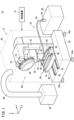
- FIG. 1 is a schematic diagram of a machine tool according to an embodiment.
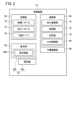
- FIG. 2 is a block diagram of the control device.
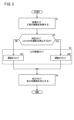
- FIG. 3 is a flowchart illustrating the control method according to the embodiment.
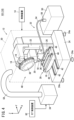
- FIG. 4 is a schematic diagram of a machine tool according to Modification 1.
- FIG. 5 is a block diagram of a control device according to a second modification.
- FIG. 1 is a schematic diagram of a machine tool 10 according to an embodiment.
- the X direction and Y direction shown in FIG. 1 are parallel to the horizontal plane. Further, the X direction and the Y direction are orthogonal to each other. Moreover, the Z direction shown in FIG. 1 is parallel to the direction of gravity. Therefore, the Z direction is orthogonal to the X direction and the Y direction. However, the Z direction shown in FIG. 1 indicates a direction opposite to the direction of gravity.
- the machine tool 10 includes a processing machine 12 and a control device 14.
- the processing machine 12 is a mechanical device that processes a workpiece using a tool 16.
- the processing machine 12 includes a spindle 18, a spindle head 20, a column 22, a pedestal 24, a table 26, a table drive section 28, a cover 30, a coolant supply device 32, and a mist collector 34.
- a tool holder 36 is attached to the main shaft 18.
- the tool holder 36 can be attached to and detached from the main shaft 18.
- Tool holder 36 holds tool 16.
- the tool 16 is, for example, a hail bit, a drill, an end mill, a milling cutter, or the like.
- the processing machine 12 further includes a tool magazine 38.
- the tool magazine 38 removably holds a plurality of tools 16.
- One tool 16 among the plurality of tools 16 held in the tool magazine 38 is replaceably attached to the tool holder 36.
- the spindle head 20 supports the spindle 18. Further, the spindle head 20 includes a motor that rotates the spindle 18. The tool 16 mounted on the spindle 18 via the tool holder 36 rotates together with the spindle 18.
- the column 22 supports the spindle head 20. Further, the column 22 includes a motor that moves the spindle head 20 in the Z direction. Column 22 is supported by pedestal 24.
- the pedestal 24 is installed on the installation surface.
- the installation surface is, for example, a factory floor.
- the installation surface may be a support surface of a stand provided on the floor.
- the installation surface extends parallel to the horizontal plane, for example.
- the pedestal 24 may include a plurality of legs 24a. Each leg 24a is, for example, a caster, a jack, or the like.
- the table drive unit 28 is supported by the pedestal 24.
- the table drive section 28 includes a first slide section 42, a saddle 44, and a second slide section 46.
- the first slide part 42 is installed on the pedestal 24.
- the first slide portion 42 includes, for example, a guide rail extending in the Y direction.
- the first slide portion 42 supports a saddle 44 .
- the saddle 44 moves in the Y direction in response to being driven by a motor (not shown). This motor is controlled by a control device 14. The saddle 44 moves while being guided by the first slide part 42.
- the second slide part 46 is installed on the saddle 44.
- the second slide portion 46 includes, for example, a guide rail extending in the X direction.
- the table 26 supports a workpiece (not shown) below the main shaft 18.
- the table 26 is supported by the second slide section 46.
- the table 26 moves in the X direction in response to being driven by a motor (not shown). This motor is controlled by a control device 14.
- the table 26 moves while being guided by the second slide section 46.
- the cover 30 covers the spindle 18, the spindle head 20, the column 22, the pedestal 24, the table 26, and the table drive section 28. Thereby, the cover 30 forms a processing area 48. The workpiece is processed within the processing area 48 .
- the cover 30 further includes a door (not shown) and a window (not shown).
- the operator can carry in workpieces into the processing area 48 through the open door. Further, the operator can easily check the condition inside the processing area 48 through the window.
- the coolant supply device 32 is a device that supplies coolant to the processing area 48.
- the coolant supply device 32 includes a coolant tank 50, a nozzle 52, a supply pipe 54, and a pump 56.
- the coolant tank 50 is a tank that stores coolant.
- the coolant tank 50 is installed outside the processing area 48.
- the nozzle 52 is a discharge part that discharges coolant. Nozzle 52 is arranged within processing area 48 . Note that the coolant supply device 32 may include a plurality of nozzles 52.
- the supply pipe 54 is a pipe that connects the coolant tank 50 and the nozzle 52.
- the coolant supply device 32 may include a plurality of supply pipes 54.
- the number of supply pipes 54 is determined depending on the number of nozzles 52, for example.
- the supply pipe 54 passes through the cover 30 and connects the coolant tank 50 and the nozzle 52.
- the pump 56 is connected to the supply pipe 54.
- the pump 56 pumps up the coolant in the coolant tank 50 and sends it to the nozzle 52. As a result, coolant is discharged from the nozzle 52 into the processing area 48 . Note that the pump 56 is controlled by the control device 14.
- the coolant discharged into the machining area 48 cools the tool 16 and the workpiece.
- the coolant discharged into the processing area 48 is vaporized, and vaporized mist is generated in the processing area 48.
- the mist collector 34 is a device that collects mist within the processing area 48.
- the mist collector 34 is installed outside the processing area 48. Further, the mist collector 34 is connected to the cover 30 via a duct 58.
- the mist collector 34 collects mist by sucking air within the processing area 48. This prevents the mist from leaking out of the processing area 48 through the small gap created in the processing machine 12.
- the mist collector 34 may be connected to the coolant tank 50. Thereby, the mist collected by the mist collector 34 can be returned to the coolant tank 50 as coolant.
- mist collector 34 and the coolant tank 50 When connecting the mist collector 34 and the coolant tank 50, it is preferable that the mist collector 34 and the coolant tank 50 are connected via a filter (not shown).
- the filtration device removes impurities from the coolant sent from the mist collector 34 to the coolant tank 50.
- clean coolant By connecting the mist collector 34 and the coolant tank 50 via a filtration device, clean coolant can be returned from the mist collector 34 to the coolant tank 50.
- Impurities in the coolant are, for example, chips collected together with the mist.
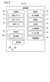
- FIG. 2 is a block diagram of the control device 14.
- the control device 14 is a computer that controls the processing machine 12.
- the control device 14 is, for example, a numerical control device.
- the control device 14 includes a display section 60, an operation section 62, a storage section 64, a calculation section 66, and a backup power supply section 68.
- the display unit 60 is a display device including a display screen 60d.
- the display unit 60 is, for example, a liquid crystal display device or an OEL (Organic Electro-Luminescence) display device.
- the operation unit 62 is an input device that accepts instructions from an operator to the control device 14.
- the operation unit 62 includes, for example, an operation panel 62a, a touch panel 62b, and the like.
- the touch panel 62b is provided on the display screen 60d.
- the operation unit 62 (operation panel 62a) may include a keyboard, a mouse, and the like.
- the storage unit 64 may include a volatile memory (not shown) and a nonvolatile memory (not shown). Examples of volatile memory include RAM (Random Access Memory). Examples of the nonvolatile memory include ROM (Read Only Memory), flash memory, and the like. Data, etc. may be stored in volatile memory, for example. Programs, tables, maps, etc. may be stored in non-volatile memory, for example. At least a portion of the storage unit 64 may be included in a processor, an integrated circuit, or the like. In this embodiment, the storage unit 64 stores a control program 70 and a machining program 72.
- the control program 70 is a program for causing the control device 14 to execute the control method according to the present embodiment. The control method will be explained later.
- the machining program 72 is a program that includes control instructions for the machining machine 12.
- the machining program 72 includes, for example, a plurality of control instructions for controlling each of the above-mentioned motors. Further, the machining program 72 includes, for example, a plurality of control instructions for controlling the coolant supply device 32.
- the machining program 72 is created or edited in advance by an operator.
- the calculation unit 66 may be configured by a processor such as a CPU (Central Processing Unit) or a GPU (Graphics Processing Unit).
- the calculation unit 66 includes a processing circuit.
- the calculation unit 66 includes a processing control unit 74, an acquisition unit 76, a determination unit 78, and a collector control unit 80.
- the processing control section 74, the acquisition section 76, the determination section 78, and the collector control section 80 are realized by the processor of the calculation section 66 executing the control program 70.
- At least a portion of the processing control section 74, the acquisition section 76, the determination section 78, and the collector control section 80 may be realized by an integrated circuit such as an ASIC (Application Specific Integrated Circuit) or an FPGA (Field-Programmable Gate Array).
- ASIC Application Specific Integrated Circuit
- FPGA Field-Programmable Gate Array
- at least a portion of the processing control section 74, the acquisition section 76, the determination section 78, and the collector control section 80 may be configured by an electronic circuit including a discrete device.
- the processing control unit 74 processes the workpiece by controlling the processing machine 12 based on the processing program 72.
- the processing control unit 74 controls mounting of the tool 16, rotation of the spindle 18, movement of the spindle head 20, movement of the table 26, and the like.
- the mist collector 34 is controlled by a collector control section 80.
- the acquisition unit 76 acquires the type of tool 16 used for machining the workpiece.
- the acquisition unit 76 starts acquiring the type of the tool 16 when attachment of the tool 16 is detected.
- the tool 16 is installed before starting machining of the workpiece. Mounting of the tool 16 also includes the case where the tool 16 is replaced with a new tool 16. Detection of attachment of the tool 16 is performed by a switch, a sensor, etc. provided on the spindle head 20. In this case, the acquisition unit 76 recognizes that attachment of the tool 16 is detected based on the detection signal output from the switch, sensor, etc., and starts acquiring the type of the tool 16.
- the acquisition unit 76 may acquire the type of the tool 16 based on the tool identification information.
- a tool table stored in the storage unit 64 is used.
- tool identification information and type information indicating the type of tool 16 are associated.
- the tool identification information is information for identifying the tool 16, and includes at least one of a tool number, tool weight, tool diameter, tool length, and tool runout.
- the tool runout is the runout of the tool 16 rotating at a predetermined rotational speed (width from the rotational axis).
- the acquisition unit 76 can acquire the type of the tool 16 corresponding to the tool number included in the machining program 72 using the tool table. Further, for example, the acquisition unit 76 can use the tool table to acquire the type of the tool 16 that corresponds to at least one of the tool weight, tool diameter, tool length, and tool runout detected by the detection mechanism.
- the detection mechanism includes a camera, a measuring device, a sensor, etc. attached to the processing machine 12. Examples of the sensor include a weight sensor, a vibration sensor, and the like.
- the acquisition unit 76 may acquire the type of tool 16 that is input from the operation unit 62 in response to an operator's operation. In this case, the acquisition unit 76 may control the display unit 60 or the like to notify the operator that the type of tool 16 should be input.
- the determination unit 78 determines whether to permit or prohibit the operation of the mist collector 34 based on the type of the tool 16 acquired by the acquisition unit 76.
- the determination table TB stored in the storage unit 64 is used.
- type information indicating the type of tool 16 is associated with status information indicating whether operation of the mist collector 34 is permitted or prohibited. For example, when the type information indicates a milling cutter or a drill, the determination unit 78 determines that operation of the mist collector 34 is permitted. Further, for example, when the type information indicates a hell bite or an end mill, the determination unit 78 determines that the operation of the mist collector 34 is prohibited.
- the determination unit 78 may determine that operation of the mist collector 34 is prohibited. Furthermore, when the type information indicates a type of tool 16 having a natural frequency that matches or approximates the vibration of the mist collector 34, the determination unit 78 may determine that the operation of the mist collector 34 is prohibited.
- the collector control unit 80 controls the mist collector 34 based on the determination result of the determination unit 78.
- the collector control unit 80 turns on the operation of the mist collector 34.
- the mist collector 34 is automatically activated and starts collecting mist from the timing when the operation of the mist collector 34 is turned on.
- the collector control unit 80 turns off the operation of the mist collector 34. In this case, the mist collector 34 is not activated.
- the backup power supply section 68 is a power source different from the main power source of the control device 14.
- the backup power supply section 68 includes, for example, a battery.
- the backup power supply section 68 is built into the control device 14 .
- the backup power supply unit 68 may be provided in the machine tool 10 as an external power supply for the control device 14. Note that illustration of the main power source of the control device 14 is omitted.
- the backup power supply section 68 supplies power to each section of the control device 14. Thereby, the collector control unit 80 can continue controlling the mist collector 34 even after the main power is turned off.
- the mist collector 34 can continue to operate even if the main power source of the control device 14 is turned off. In that case, the main power of the control device 14 may be turned off before the collector control section 80 stops the mist collector 34. In such a case, by being supplied with power from the backup power supply section 68, the collector control section 80 can automatically stop the mist collector 34 even after the main power supply of the control device 14 is turned off. This prevents the mist collector 34 from consuming power unnecessarily.
- FIG. 3 is a flowchart illustrating the control method according to the embodiment.
- the control device 14 can execute the control method illustrated in FIG. 3, for example.
- the control method in FIG. 3 includes an acquisition step S1, a determination step S2, a collector control step S3, and a processing step S4.
- the collector control step S3 includes an operation-on step S31 and an operation-off step S32.
- the acquisition step S1, the determination step S2, and the collector control step S3 are executed before starting machining of the workpiece.
- the acquisition step S1 is a step of acquiring the type of the tool 16.
- the type of the tool 16 is acquired by the acquisition unit 76.
- the acquisition unit 76 analyzes the machining program 72 that caused the attachment of the tool 16 to be executed, and acquires the type of the tool 16.
- the determination step S2 is a step of determining whether to permit or prohibit the operation of the mist collector 34 based on the type of the tool 16 acquired in the acquisition step S1.
- the determination unit 78 determines whether to permit or prohibit the operation of the mist collector 34 based on the determination table TB.
- the determination unit 78 determines that the operation of the mist collector 34 is permitted. judge. Conversely, when the state information in the determination table TB corresponding to the type of tool 16 acquired in the acquisition step S1 indicates that the operation of the mist collector 34 is prohibited (S2: YES), the determination unit 78 prohibits the operation of the mist collector 34. is determined to be prohibited. Depending on the determination made in the determination step S2, a driving-on step S31 or a driving-off step S32 is started.
- the operation on step S31 is a step for turning on the operation of the mist collector 34.
- the collector control unit 80 turns on the operation of the mist collector 34. In this case, processing of the workpiece is started after the mist collector 34 starts collecting mist.
- the operation off step S32 is a step for turning off the operation of the mist collector 34.
- the operation of the mist collector 34 is turned off by the collector control unit 80. In this case, processing of the workpiece is started without collecting the mist by the mist collector 34.
- the processing step S4 is a step of processing the workpiece.
- the processing object is processed under the control of the processing control unit 74 for the processing machine 12.
- the machining control unit 74 processes the workpiece based on the machining program 72 that causes the tool 16 to be mounted on the spindle 18.
- the control method of FIG. 3 ends when the processing of the workpiece is completed.
- the collector control unit 80 stops the mist collector 34 at the timing when processing of the workpiece is completed. In this case, when the stop of the mist collector 34 ends, the control method of FIG. 3 ends.
- the type of the tool 16 used to process the workpiece is acquired, and based on the type of the tool 16, it is determined whether to permit or prohibit the operation of the mist collector 34. If a determination is made to permit operation of the mist collector 34, the operation by the mist collector 34 is turned on, and if a determination is made to prohibit the operation of the mist collector 34, the operation by the mist collector 34 is turned off. be done.
- FIG. 4 is a schematic diagram of a machine tool 101 (10) according to modification example 1.
- the machine tool 101 further includes a sub-control device 82. Note that in the machine tool 101, the backup power supply unit 68 of the control device 14 may be omitted.
- the sub-control device 82 is a computer separate from the control device 14.
- the sub-control device 82 includes, for example, a processor and a memory.
- the sub-control device 82 may include an integrated circuit, a discrete device, or the like.
- the sub-control device 82 controls the mist collector 34 instead of the collector control section 80. Therefore, even if the control device 14 stops, the mist collector 34 is controlled by the sub-control device 82 in the same manner as in the embodiment.
- the control device 14 when machining is completed, the operator instructs the control device 14 to stop immediately. As a result, the control device 14 immediately stops after finishing the machining. However, as described above, it is preferable that the mist collector 34 collects the mist until a predetermined period of time has passed after the processing is completed. In such a case, the sub-control device 82 can control the mist collector 34 instead of the control device 14.
- the sub-control device 82 may control the mist collector 34 instead of the control device 14. can.
- the sub-control device 82 and the control device 14 communicate as appropriate and share data necessary for controlling the mist collector 34.
- the sub-control device 82 and the control device 14 share the type of tool 16 acquired by the acquisition unit 76, the content of the determination by the determination unit 78, and the progress of machining.
- the sub-control device 82 can smoothly take over the control that was being performed by the collector control section 80. According to this modification, even after the control device 14 is stopped, the control of the mist collector 34 can be continued by the sub-control device 82.
- FIG. 5 is a block diagram of a control device 142 (14) according to the second modification.
- the control device 142 further includes an alarm output section 84.
- the alarm output unit 84 outputs an alarm when an abnormality occurs in the machine tool 10.
- the machine tool 10 is appropriately equipped with sensors (not shown) for detecting failures in various parts such as the spindle 18, the spindle head 20, and the table drive section 28.
- the alarm output unit 84 determines whether a failure has occurred in the machine tool 10 based on the signal output by the sensor. When a failure in each part of the machine tool 10 is detected, the alarm output section 84 notifies the operator of the occurrence of the failure, for example, via the display section 60.
- the machining control unit 74 does not start machining until the cause of the alarm is resolved. Furthermore, if the alarm output section 84 outputs an alarm after the start of machining, the machining control section 74 suspends the machining based on the machining program 72 until the cause of the alarm is resolved.
- the collector control unit 80 stops the operation of the mist collector 34 until the cause of the alarm is eliminated. This can prevent the mist collector 34 from continuing to operate in the event of an emergency for the machine tool 10. However, if the operator issues an instruction to start operation when the processing machine 12 stops abnormally, the collector control section 80 may restart the operation of the mist collector 34.
- the mist collector 34 stops when the processing control unit 74 finishes processing.
- the collector control unit 80 may control the mist collector 34 to cause the mist collector 34 to collect the mist in the processing area 48 until a predetermined time has elapsed from the end of the processing.
- the predetermined time is, for example, instructed in advance to the collector control unit 80 via the operation unit 62 by an operator. However, the predetermined time may be specified by the manufacturer of the machine tool 10.
- the collector control unit 80 causes the mist collector 34 to start collecting mist before processing of the workpiece is started.
- the collector control unit 80 may cause the mist collector 34 to start collecting mist after a predetermined standby time has elapsed after processing of the workpiece is started.
- the standby time is, for example, instructed in advance to the collector control unit 80 by the operator via the operation unit 62.
- the standby time may be specified by the manufacturer of the machine tool 10.
- the collector control unit 80 receives an operator's instruction to permit the operation of the mist collector 34. You may accept it. When there is an instruction to permit operation of the mist collector 34, the collector control unit 80 turns on the operation of the mist collector 34 even if a determination has been made to prohibit the operation. Similarly, after the determination is made to permit operation of the mist collector 34 and until the processing of the workpiece is completed, the collector control unit 80 receives an instruction from the operator to prohibit the operation of the mist collector 34. It's okay.
- the collector control unit 80 When there is an instruction to prohibit the operation of the mist collector 34, the collector control unit 80 turns off the operation of the mist collector 34 even if a determination has been made to permit the operation. In this way, when receiving an instruction from the operator to permit or prohibit the operation of the mist collector 34, the collector control unit 80 gives priority to the instruction and controls the operation of the mist collector 34, regardless of the determination by the determination unit 78. Turn on or off. Thereby, the operation of the mist collector 34 can be turned on and off with priority given to the operator's intention.
- the determination unit 78 may determine whether to permit or prohibit the operation of the mist collector 34 based on the type of the tool 16 and the material of the workpiece.
- the material of the workpiece may be added to the determination table TB or may be input by the operator.
- the vibrations (processing vibrations) generated when processing the workpiece may resonate with the vibrations (collector vibrations) generated from the mist collector 34 . Machining vibrations depend not only on the tool 16 but also on the material of the workpiece. Therefore, when the material of the workpiece is added to the judgment conditions of the judgment unit 78, when there is a possibility that the collector vibration and the processing vibration resonate, it is possible to appropriately make a judgment to prohibit the operation of the mist collector 34. I can do it.
- the processing control unit 74 may control the coolant pump 56 in accordance with the operating state of the mist collector 34. That is, when the determination unit 78 makes a determination to permit operation of the mist collector 34, the processing control unit 74 drives the coolant pump 56. On the other hand, when the determination section 78 makes a determination to prohibit the operation of the mist collector 34, the processing control section 74 does not drive the coolant pump 56. In this way, it is possible to prevent vibrations generated from the coolant supply device 32 from affecting the machining of the workpiece.
- the status information may be defined in the machining program 72 as an option.
- the determination unit 78 can determine whether to permit or prohibit operation of the mist collector 34 based on the processing program 72. Therefore, the determination table TB does not need to be stored in the storage unit 64. Therefore, the storage capacity of the storage unit 64 can be reduced.
- the coolant discharge method is not limited to the embodiment.
- the coolant may be discharged using a center-through method, for example.
- the coolant supply device 32 supplies coolant to the main shaft 18 .
- the coolant may be flowed along the inner wall of the cover 30 (processing area 48).
- the processing machine 12 may further include a recovery member (not shown) for recovering coolant that falls below the table 26.
- the collection member is, for example, an oil pan provided on the pedestal 24. Some of the coolant supplied to the processing area 48 does not become mist and falls below the table 26. According to this modification, coolant that has fallen below the table 26 can be recovered.
- the collected coolant may be returned to the coolant tank 50. Thereby, the coolant supply device 32 can reuse the collected coolant.
- a filtration device filter
- clean coolant can be returned to the coolant tank 50.
- the first invention provides a control device (14) for a machine tool (10) that processes a workpiece in the processing area, and includes a mist collector (34) that collects mist in the processing area (48).
- a mist collector (34) that collects mist in the processing area (48).
- an acquisition unit (76) that acquires the type of the tool (16) used to process the workpiece; and an acquisition unit (76) that determines whether to permit or prohibit operation of the mist collector based on the type of the tool.
- a determination unit (78) that makes a determination, and if a determination is made to permit operation of the mist collector, turn on the operation by the mist collector, and if a determination is made to prohibit operation of the mist collector.
- the control device includes a collector control section (80) that turns off operation by the mist collector.
- the first invention is a control device, wherein the collector control unit has type information indicating the type of the tool and status information indicating whether to permit or prohibit operation of the mist collector.
- An attached judgment table (TB) may also be used. This makes it possible to manage tools for turning on and off the operation of the mist collector.
- the first invention is a control device, and when the type of the tool used for precision machining is acquired, the collector control section may turn off operation by the mist collector. Thereby, it is possible to suppress reduction in processing accuracy of precision processing.
- a first aspect of the invention is a control device, in which the acquisition unit may start acquiring the type of the attached tool when attachment of the tool is detected. Thereby, even if the tool is replaced, the operation of the mist collector can be turned on or off based on the type of tool after replacement.
- a first invention is a control device, wherein the collector control section determines whether to permit or prohibit operation of the mist collector before processing of the workpiece is started. Good too. This makes it possible to prevent the mist collector from turning on before the start of machining when machining is performed using a type of tool for which mist collector operation is prohibited.
- a first aspect of the invention is a control device, in which when a determination is made to permit operation of the mist collector, the collector control section controls the mist collector so that a predetermined period of time has elapsed since the end of processing of the workpiece. After that, the driving of the mist collector may be stopped. Thereby, it is possible to reduce the amount of mist remaining in the processing area after finishing the processing, and to prevent the power consumption of the mist collector from increasing more than necessary.
- the first invention is a control device, further comprising an alarm output section (84) that outputs an alarm when an abnormality occurs in the machine tool, and when the mist collector is turned on. If the alarm is output at , the collector control section may stop the operation of the mist collector. This can prevent the mist collector from continuing to operate in the event of an emergency for the machine tool.
- a second invention is a machine tool (10) having the control device according to the first invention. Since the control device according to the first invention is provided, reduction in processing accuracy can be suppressed.
- a second aspect of the invention is a machine tool, which may further include a sub-control device (82) that controls the mist collector in place of the collector control section when the control device stops. Thereby, even if the control device is stopped, the mist collector can be controlled.
- the third invention is a control method in which a computer (14) controls a machine tool that is equipped with a mist collector that collects mist in a machining area and processes a workpiece in the machining area, an acquisition step (S1) of acquiring the type of tool used to process the workpiece; a determination step (S2) of determining whether to permit or prohibit operation of the mist collector based on the type of the tool; If a determination is made to permit operation of the mist collector, the operation by the mist collector is turned on; if a determination is made to prohibit the operation of the mist collector, operation by the mist collector is turned off.
- This is a control method including a collector control step (S3).
Landscapes
- Engineering & Computer Science (AREA)
- Physics & Mathematics (AREA)
- General Physics & Mathematics (AREA)
- Automation & Control Theory (AREA)
- Mechanical Engineering (AREA)
- Human Computer Interaction (AREA)
- Manufacturing & Machinery (AREA)
- Auxiliary Devices For Machine Tools (AREA)
Abstract
Description
図1は、実施形態に係る工作機械10の模式図である。
以下には、上記実施形態に係る変形例が記載される。ただし、上記実施形態と重複する説明は、以下の説明では適宜省略される。上記実施形態で説明済みの要素には、特に断らない限り、上記実施形態と同一の参照符号が付される。
図4は、変形例1に係る工作機械101(10)の模式図である。工作機械101は、サブ制御装置82をさらに備える。なお、工作機械101において、制御装置14の予備電源部68は、省略されてもよい。
図5は、変形例2に係る制御装置142(14)のブロック図である。制御装置142は、アラーム出力部84をさらに備える。
前述された複数の変形例は、矛盾しない範囲内において適宜組み合わされてもよい。
本発明は、上述した実施形態に限らず、本発明の要旨を逸脱することなく、種々の構成を取り得る。
以下には、上記実施形態および変形例から把握しうる発明が記載される。
14、142…制御装置 32…クーラント供給器
34…ミストコレクタ 48…加工エリア
72…加工プログラム 74…加工制御部
76…取得部 78…判定部
80…コレクタ制御部 82…サブ制御装置
84…アラーム出力部 TB…判定テーブル
Claims (10)
- 加工エリア(48)内のミストを回収するミストコレクタ(34)を備え、前記加工エリア内で加工対象物を加工する工作機械(10)の制御装置(14)であって、
前記加工対象物の加工に用いられる工具(16)の種類を取得する取得部(76)と、
前記工具の種類に基づいて、前記ミストコレクタの運転を許可するか禁止するかを判定する判定部(78)と、
前記ミストコレクタの運転を許可する判定が行われた場合は、前記ミストコレクタによる運転をオンにし、前記ミストコレクタの運転を禁止する判定が行われた場合は、前記ミストコレクタによる運転をオフにするコレクタ制御部(80)と、
を備える、制御装置。 - 請求項1に記載の制御装置であって、
前記コレクタ制御部は、前記工具の種類を示す種類情報と、前記ミストコレクタの運転を許可するか禁止するかを示す状態情報とが対応付けられた判定テーブル(TB)を用いる、制御装置。 - 請求項1または2に記載の制御装置であって、
精密加工に用いられる前記工具の種類が取得された場合、前記コレクタ制御部は、前記ミストコレクタによる運転をオフにする、制御装置。 - 請求項1~3のいずれか1項に記載の制御装置であって、
前記取得部は、前記工具の装着が検出された場合に、装着された前記工具の種類の取得を開始する、制御装置。 - 請求項1~4のいずれか1項に記載の制御装置であって、
前記コレクタ制御部は、前記加工対象物の加工が開始される前に、前記ミストコレクタの運転を許可するか禁止するかを判定する、制御装置。 - 請求項1~5のいずれか1項に記載の制御装置であって、
前記ミストコレクタの運転を許可する判定が行われた場合は、前記コレクタ制御部は、前記加工対象物の加工の終了から所定時間が経過した後に前記ミストコレクタの駆動を停止させる、制御装置。 - 請求項1~6のいずれか1項に記載の制御装置であって、
前記工作機械に異常が発生した場合にアラームを出力するアラーム出力部(84)をさらに備え、
前記ミストコレクタの運転がオンされている場合に前記アラームが出力された場合は、前記コレクタ制御部は、前記ミストコレクタの運転を停止させる、制御装置。 - 請求項1~7のいずれか1項に記載の制御装置を有する、工作機械。
- 請求項8に記載の工作機械であって、
前記制御装置が停止した場合において前記コレクタ制御部に代わって前記ミストコレクタを制御するサブ制御装置(82)をさらに備える、工作機械。 - 加工エリア内のミストを回収するミストコレクタを備え、前記加工エリア内で加工対象物を加工する工作機械をコンピュータ(14)が制御する制御方法であって、
前記加工対象物の加工に用いられる工具の種類を取得する取得ステップ(S1)と、
前記工具の種類に基づいて、前記ミストコレクタの運転を許可するか禁止するかを判定する判定ステップ(S2)と、
前記ミストコレクタの運転を許可する判定が行われた場合は、前記ミストコレクタによる運転をオンにし、前記ミストコレクタの運転を禁止する判定が行われた場合は、前記ミストコレクタによる運転をオフにするコレクタ制御ステップ(S3)と、
を含む、制御方法。
Priority Applications (5)
| Application Number | Priority Date | Filing Date | Title |
|---|---|---|---|
| US18/862,641 US20250282015A1 (en) | 2022-05-12 | 2022-05-12 | Control device, machine tool, and control method |
| JP2022545337A JP7148764B1 (ja) | 2022-05-12 | 2022-05-12 | 制御装置、工作機械および制御方法 |
| PCT/JP2022/020030 WO2023218591A1 (ja) | 2022-05-12 | 2022-05-12 | 制御装置、工作機械および制御方法 |
| CN202280095708.2A CN119136942A (zh) | 2022-05-12 | 2022-05-12 | 控制装置、机床及控制方法 |
| DE112022006811.6T DE112022006811T5 (de) | 2022-05-12 | 2022-05-12 | Steuervorrichtung, werkzeugmaschine und steuerverfahren |
Applications Claiming Priority (1)
| Application Number | Priority Date | Filing Date | Title |
|---|---|---|---|
| PCT/JP2022/020030 WO2023218591A1 (ja) | 2022-05-12 | 2022-05-12 | 制御装置、工作機械および制御方法 |
Publications (1)
| Publication Number | Publication Date |
|---|---|
| WO2023218591A1 true WO2023218591A1 (ja) | 2023-11-16 |
Family
ID=83507339
Family Applications (1)
| Application Number | Title | Priority Date | Filing Date |
|---|---|---|---|
| PCT/JP2022/020030 Ceased WO2023218591A1 (ja) | 2022-05-12 | 2022-05-12 | 制御装置、工作機械および制御方法 |
Country Status (5)
| Country | Link |
|---|---|
| US (1) | US20250282015A1 (ja) |
| JP (1) | JP7148764B1 (ja) |
| CN (1) | CN119136942A (ja) |
| DE (1) | DE112022006811T5 (ja) |
| WO (1) | WO2023218591A1 (ja) |
Families Citing this family (2)
| Publication number | Priority date | Publication date | Assignee | Title |
|---|---|---|---|---|
| JP7454736B1 (ja) | 2023-09-15 | 2024-03-22 | ユアサネオテック株式会社 | プログラム及び工作機械システム |
| WO2026033578A1 (ja) * | 2024-08-05 | 2026-02-12 | ファナック株式会社 | 工作機械の制御装置および加工システム |
Citations (5)
| Publication number | Priority date | Publication date | Assignee | Title |
|---|---|---|---|---|
| US5730037A (en) * | 1995-04-17 | 1998-03-24 | Logan Clutch Corporation | Multi-spindle machine control systems |
| JP2017091242A (ja) * | 2015-11-11 | 2017-05-25 | ファナック株式会社 | ミスト除去システム、およびその方法 |
| JP6970319B1 (ja) * | 2021-06-09 | 2021-11-24 | Dmg森精機株式会社 | 工作機械、制御方法、および制御プログラム |
| JP6970318B1 (ja) * | 2021-06-09 | 2021-11-24 | Dmg森精機株式会社 | 工作機械、制御方法、および制御プログラム |
| JP7007513B1 (ja) * | 2021-06-02 | 2022-01-24 | Dmg森精機株式会社 | 工作機械、制御方法、および制御プログラム |
-
2022
- 2022-05-12 DE DE112022006811.6T patent/DE112022006811T5/de active Pending
- 2022-05-12 JP JP2022545337A patent/JP7148764B1/ja active Active
- 2022-05-12 CN CN202280095708.2A patent/CN119136942A/zh active Pending
- 2022-05-12 US US18/862,641 patent/US20250282015A1/en active Pending
- 2022-05-12 WO PCT/JP2022/020030 patent/WO2023218591A1/ja not_active Ceased
Patent Citations (5)
| Publication number | Priority date | Publication date | Assignee | Title |
|---|---|---|---|---|
| US5730037A (en) * | 1995-04-17 | 1998-03-24 | Logan Clutch Corporation | Multi-spindle machine control systems |
| JP2017091242A (ja) * | 2015-11-11 | 2017-05-25 | ファナック株式会社 | ミスト除去システム、およびその方法 |
| JP7007513B1 (ja) * | 2021-06-02 | 2022-01-24 | Dmg森精機株式会社 | 工作機械、制御方法、および制御プログラム |
| JP6970319B1 (ja) * | 2021-06-09 | 2021-11-24 | Dmg森精機株式会社 | 工作機械、制御方法、および制御プログラム |
| JP6970318B1 (ja) * | 2021-06-09 | 2021-11-24 | Dmg森精機株式会社 | 工作機械、制御方法、および制御プログラム |
Also Published As
| Publication number | Publication date |
|---|---|
| JP7148764B1 (ja) | 2022-10-05 |
| DE112022006811T5 (de) | 2024-12-24 |
| CN119136942A (zh) | 2024-12-13 |
| JPWO2023218591A1 (ja) | 2023-11-16 |
| US20250282015A1 (en) | 2025-09-11 |
Similar Documents
| Publication | Publication Date | Title |
|---|---|---|
| JP7148764B1 (ja) | 制御装置、工作機械および制御方法 | |
| JP3645353B2 (ja) | 工具磨耗検出機能付工作機械 | |
| CN109308052B (zh) | 数值控制装置以及数值控制方法 | |
| US7313458B2 (en) | NC machine Tool | |
| JP6664986B2 (ja) | 加工装置 | |
| JPH10286743A (ja) | 工作機械の工具異常検出装置及び工作機械の工具異常検出用プログラムを記録した記録媒体 | |
| JP7148763B1 (ja) | 制御装置、工作機械および制御方法 | |
| US20160151934A1 (en) | Dust removal system for a handheld power tool | |
| CN101683714B (zh) | 机床的主轴装置 | |
| JPH11170142A (ja) | 主軸異常監視装置 | |
| JP5711015B2 (ja) | 定寸装置 | |
| WO2023218590A1 (ja) | 制御装置、工作機械および制御方法 | |
| JP7827855B2 (ja) | プログラム編集装置、工作機械およびプログラム編集方法 | |
| JP2007030158A (ja) | 工具の座またはアンバランスを検査するための方法 | |
| JP4349308B2 (ja) | 工作機械の制御装置 | |
| JP2003271213A (ja) | 移動軸監視装置、移動軸監視方法、移動軸監視プログラムおよびその移動軸監視プログラムを記録したコンピュータ読取り可能な記録媒体 | |
| JP7208425B1 (ja) | 異常検出装置 | |
| JP3510083B2 (ja) | 研削装置 | |
| US20230286096A1 (en) | Machine tool and machine tool control system | |
| JPS63102854A (ja) | 異常工具交換方法 | |
| JP2018182178A (ja) | 加工装置の診断方法 | |
| JP2002333908A (ja) | 工作機械 | |
| JP4261708B2 (ja) | Nc加工装置 | |
| JP2007015042A (ja) | 研削装置 | |
| JP2847763B2 (ja) | 刃具回転振れの管理方法 |
Legal Events
| Date | Code | Title | Description |
|---|---|---|---|
| ENP | Entry into the national phase |
Ref document number: 2022545337 Country of ref document: JP Kind code of ref document: A |
|
| 121 | Ep: the epo has been informed by wipo that ep was designated in this application |
Ref document number: 22941671 Country of ref document: EP Kind code of ref document: A1 |
|
| WWE | Wipo information: entry into national phase |
Ref document number: 112022006811 Country of ref document: DE |
|
| WWE | Wipo information: entry into national phase |
Ref document number: 202280095708.2 Country of ref document: CN Ref document number: 18862641 Country of ref document: US |
|
| 122 | Ep: pct application non-entry in european phase |
Ref document number: 22941671 Country of ref document: EP Kind code of ref document: A1 |
|
| WWP | Wipo information: published in national office |
Ref document number: 18862641 Country of ref document: US |