WO2023218586A1 - エアロゾル生成システム、及びエアロゾル生成システムの製造方法 - Google Patents
エアロゾル生成システム、及びエアロゾル生成システムの製造方法 Download PDFInfo
- Publication number
- WO2023218586A1 WO2023218586A1 PCT/JP2022/020019 JP2022020019W WO2023218586A1 WO 2023218586 A1 WO2023218586 A1 WO 2023218586A1 JP 2022020019 W JP2022020019 W JP 2022020019W WO 2023218586 A1 WO2023218586 A1 WO 2023218586A1
- Authority
- WO
- WIPO (PCT)
- Prior art keywords
- layer
- cylindrical member
- generation system
- heat
- aerosol generation
- Prior art date
- Legal status (The legal status is an assumption and is not a legal conclusion. Google has not performed a legal analysis and makes no representation as to the accuracy of the status listed.)
- Ceased
Links
Images








Classifications
-
- A—HUMAN NECESSITIES
- A24—TOBACCO; CIGARS; CIGARETTES; SIMULATED SMOKING DEVICES; SMOKERS' REQUISITES
- A24F—SMOKERS' REQUISITES; MATCH BOXES; SIMULATED SMOKING DEVICES
- A24F40/00—Electrically operated smoking devices; Component parts thereof; Manufacture thereof; Maintenance or testing thereof; Charging means specially adapted therefor
- A24F40/40—Constructional details, e.g. connection of cartridges and battery parts
- A24F40/46—Shape or structure of electric heating means
-
- A—HUMAN NECESSITIES
- A24—TOBACCO; CIGARS; CIGARETTES; SIMULATED SMOKING DEVICES; SMOKERS' REQUISITES
- A24F—SMOKERS' REQUISITES; MATCH BOXES; SIMULATED SMOKING DEVICES
- A24F40/00—Electrically operated smoking devices; Component parts thereof; Manufacture thereof; Maintenance or testing thereof; Charging means specially adapted therefor
- A24F40/20—Devices using solid inhalable precursors
-
- A—HUMAN NECESSITIES
- A24—TOBACCO; CIGARS; CIGARETTES; SIMULATED SMOKING DEVICES; SMOKERS' REQUISITES
- A24F—SMOKERS' REQUISITES; MATCH BOXES; SIMULATED SMOKING DEVICES
- A24F40/00—Electrically operated smoking devices; Component parts thereof; Manufacture thereof; Maintenance or testing thereof; Charging means specially adapted therefor
- A24F40/70—Manufacture
-
- H—ELECTRICITY
- H05—ELECTRIC TECHNIQUES NOT OTHERWISE PROVIDED FOR
- H05B—ELECTRIC HEATING; ELECTRIC LIGHT SOURCES NOT OTHERWISE PROVIDED FOR; CIRCUIT ARRANGEMENTS FOR ELECTRIC LIGHT SOURCES, IN GENERAL
- H05B3/00—Ohmic-resistance heating
- H05B3/10—Heating elements characterised by the composition or nature of the materials or by the arrangement of the conductor
- H05B3/12—Heating elements characterised by the composition or nature of the materials or by the arrangement of the conductor characterised by the composition or nature of the conductive material
- H05B3/14—Heating elements characterised by the composition or nature of the materials or by the arrangement of the conductor characterised by the composition or nature of the conductive material the material being non-metallic
- H05B3/145—Carbon only, e.g. carbon black, graphite
-
- H—ELECTRICITY
- H05—ELECTRIC TECHNIQUES NOT OTHERWISE PROVIDED FOR
- H05B—ELECTRIC HEATING; ELECTRIC LIGHT SOURCES NOT OTHERWISE PROVIDED FOR; CIRCUIT ARRANGEMENTS FOR ELECTRIC LIGHT SOURCES, IN GENERAL
- H05B3/00—Ohmic-resistance heating
- H05B3/20—Heating elements having extended surface area substantially in a two-dimensional [2D] plane, e.g. plate-heater
- H05B3/34—Heating elements having extended surface area substantially in a two-dimensional [2D] plane, e.g. plate-heater flexible, e.g. heating nets or webs
-
- H—ELECTRICITY
- H05—ELECTRIC TECHNIQUES NOT OTHERWISE PROVIDED FOR
- H05B—ELECTRIC HEATING; ELECTRIC LIGHT SOURCES NOT OTHERWISE PROVIDED FOR; CIRCUIT ARRANGEMENTS FOR ELECTRIC LIGHT SOURCES, IN GENERAL
- H05B3/00—Ohmic-resistance heating
- H05B3/40—Heating elements having the shape of rods or tubes
- H05B3/42—Heating elements having the shape of rods or tubes non-flexible
- H05B3/46—Heating elements having the shape of rods or tubes non-flexible heating conductor mounted on insulating base
-
- H—ELECTRICITY
- H01—ELECTRIC ELEMENTS
- H01B—CABLES; CONDUCTORS; INSULATORS; SELECTION OF MATERIALS FOR THEIR CONDUCTIVE, INSULATING OR DIELECTRIC PROPERTIES
- H01B3/00—Insulators or insulating bodies characterised by the insulating materials; Selection of materials for their insulating or dielectric properties
- H01B3/18—Insulators or insulating bodies characterised by the insulating materials; Selection of materials for their insulating or dielectric properties mainly consisting of organic substances
- H01B3/30—Insulators or insulating bodies characterised by the insulating materials; Selection of materials for their insulating or dielectric properties mainly consisting of organic substances plastics; resins; waxes
- H01B3/303—Macromolecular compounds obtained by reactions forming a linkage containing nitrogen with or without oxygen or carbon in the main chain of the macromolecule, not provided for in groups H01B3/38 or H01B3/302
- H01B3/306—Polyimides or polyesterimides
-
- H—ELECTRICITY
- H05—ELECTRIC TECHNIQUES NOT OTHERWISE PROVIDED FOR
- H05B—ELECTRIC HEATING; ELECTRIC LIGHT SOURCES NOT OTHERWISE PROVIDED FOR; CIRCUIT ARRANGEMENTS FOR ELECTRIC LIGHT SOURCES, IN GENERAL
- H05B2203/00—Aspects relating to Ohmic resistive heating covered by group H05B3/00
- H05B2203/021—Heaters specially adapted for heating liquids
Definitions
- the present invention relates to an aerosol generation system and a method of manufacturing the aerosol generation system.
- a suction device generates an aerosol to which a flavor component has been added using a base material that includes an aerosol source for generating an aerosol, a flavor source for imparting a flavor component to the generated aerosol, and the like.
- the user can taste the flavor by inhaling the aerosol to which the flavor component is added, which is generated by the suction device.
- the action of the user inhaling an aerosol will also be referred to below as a puff or a puff action.
- Patent Document 1 listed below discloses a technique for heating a base material using a single film heater wound into a tubular shape so as to surround the base material.
- a film heater is wrapped around the outside of a cylindrical member that houses a base material.
- simply wrapping the film heater around the cylindrical member may make it difficult to properly heat the base material.
- the present invention has been made in view of the above problems, and an object of the present invention is to provide a mechanism that can heat a base material more appropriately.
- a cylindrical member having an opening into which an aerosol generating article containing an aerosol source can be inserted; and a thermal diffusion layer in which a first layer having a thermal conductivity equal to or higher than a first threshold value and a second layer having a tensile strength equal to or higher than a second threshold value are laminated;
- An aerosol generation system wherein the diffusion layer is arranged so as to wrap around the outside of the heating section arranged on the outer surface of the cylindrical member, with the first layer being inside and the second layer being outside. is provided.
- the second layer is formed to be longer than the first layer in the circumferential direction of the cylindrical member, and the heat diffusion layer is formed such that the second layer extends over the entire circumferential direction of the cylindrical member.
- the first layer and the second layer may be bonded and formed so as to cover the first layer.
- the second layer includes a first portion formed longer than the first layer in the height direction of the cylindrical member, and of the first portion of the second layer, the cylindrical member Both end portions protruding from the first layer in the height direction may be adhered to the heating section.
- the heating section includes a film-like electrically insulating base material and a conductive track disposed on the electrically insulating base material, and the both end portions of the first section of the second layer are connected to the heating section.
- the conductive track may be bonded to a blank area where the conductive track is not placed, which is adjacent in the height direction of the cylindrical member to a portion of the conductive track where a heat generating part that generates heat when a current is applied is placed. good.
- the second layer includes a second portion formed such that the length in the circumferential direction of the cylindrical member is longer than the outer circumferential length of the cylindrical member, and among the second portion of the second layer, A protruding portion that protrudes from the first layer in the circumferential direction of the cylindrical member may be bonded to the second layer that is wound one circumference inward from the protruding portion.
- the second portion of the second layer may be formed shorter than the first layer in the height direction of the cylindrical member.
- the first layer may be formed to be longer than the outer circumferential length of the cylindrical member in the circumferential direction of the cylindrical member.
- the heating section includes a film-like electrically insulating base material and a conductive track disposed on the electrically insulating base material, and the heating section covers a part of the outer surface of the cylindrical member. It may be placed on the outer surface of the cylindrical member with a portion exposed.
- the heating section may be formed in a T-shape or a shape having a notch in plan view.
- the aerosol generation system includes a heat-insulating layer whose thermal conductivity is less than a third threshold, and a heat-shrinkable tube that shrinks when heated, and the heating section and the heat-diffusion layer are connected to the cylindrical member.
- the heat shrink tube may be wrapped around the outer surface of the tube and fixed to the cylindrical member using a heat shrink tube while being covered with the heat insulating layer.
- the first layer may be formed of copper, graphite, or aluminum.
- the second layer may be formed of PI (Polyimide).
- the cylindrical member may be formed of SUS (steel use stainless).
- a first layer having a thermal conductivity greater than or equal to a first threshold value and a second layer having a tensile strength greater than or equal to a second threshold value are provided. bonding a heat diffusion layer in which the first layer is laminated to a film-like heating section with the first layer on the inside; and bonding the bonded heating section and the heat diffusion layer with the heating section on the inside; Disposing an aerosol generating article containing an aerosol source on an outer surface of a tubular member having an insertable opening is provided.
- a mechanism is provided that allows a base material to be heated more appropriately.
- FIG. 2 is a schematic diagram schematically showing a configuration example of a suction device.
- FIG. 1 is a perspective view schematically showing an example of a heater assembly according to the present embodiment.
- FIG. 3 is a diagram schematically showing an example of a cross section of the heater assembly taken along arrow AA.
- FIG. 2 is a perspective view schematically showing an example of a housing section according to the present embodiment.
- FIG. 2 is a developed view of an example of a heating section according to the present embodiment.
- FIG. 1 is a developed view of an example of a heat diffusion sheet according to the present embodiment. It is a flowchart which shows an example of the manufacturing method of the heater assembly concerning this embodiment. It is a figure showing typically an example of the manufacturing method of the heater assembly concerning this embodiment.
- FIG. 7 is a perspective view schematically showing an example of a heater assembly according to a second supplement. It is a perspective view which shows an example of the state before the heating part 40 based on the 2nd addition is arrange
- a suction device is a device that produces a substance that is inhaled by a user.
- the substance generated by the suction device is an aerosol.
- the substance produced by the suction device may be a gas.
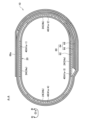
- FIG. 1 is a schematic diagram schematically showing a configuration example of a suction device.
- the suction device 100 according to the present configuration example includes a power supply section 111, a sensor section 112, a notification section 113, a storage section 114, a communication section 115, a control section 116, a storage section 20, a heating section 40, and It includes a heat insulating section 70.
- the power supply unit 111 stores power. Then, the power supply unit 111 supplies power to each component of the suction device 100 based on control by the control unit 116.
- the power supply unit 111 may be configured with a rechargeable battery such as a lithium ion secondary battery, for example.
- the sensor unit 112 acquires various information regarding the suction device 100.
- the sensor unit 112 includes a pressure sensor such as a condenser microphone, a flow rate sensor, a temperature sensor, etc., and acquires a value associated with suction by the user.
- the sensor unit 112 is configured with an input device such as a button or a switch that receives information input from the user.
- the notification unit 113 notifies the user of information.
- the notification unit 113 includes, for example, a light emitting device that emits light, a display device that displays an image, a sound output device that outputs sound, a vibration device that vibrates, or the like.
- the storage unit 114 stores various information for the operation of the suction device 100.
- the storage unit 114 is configured by, for example, a nonvolatile storage medium such as a flash memory.
- the communication unit 115 is a communication interface that can perform communication compliant with any wired or wireless communication standard.
- Such communication standards include, for example, Wi-Fi (registered trademark), Bluetooth (registered trademark), BLE (Bluetooth Low Energy (registered trademark)), NFC (Near Field Communication), or LPWA (Low Power Wide Area). Standards etc. may be adopted.
- the control unit 116 functions as an arithmetic processing device and a control device, and controls overall operations within the suction device 100 according to various programs.
- the control unit 116 is realized by, for example, an electronic circuit such as a CPU (Central Processing Unit) or a microprocessor.
- the accommodating part 20 has an internal space 30 and holds the stick-type base material 150 while accommodating a part of the stick-type base material 150 in the internal space 30.
- the accommodating portion 20 is configured such that the stick-type base material 150 can be inserted through the opening 22.
- the accommodating portion 20 has an opening 22 that communicates the internal space 30 with the outside, and accommodates the stick-shaped base material 150 inserted into the internal space 30 from the opening 22.
- the accommodating portion 20 is a cylindrical member having an opening 22 and a bottom wall 26 at both ends, and defines a columnar internal space 30. An air flow path that supplies air to the internal space 30 is connected to the housing section 20 .
- An air inflow hole which is an inlet of air to the air flow path, is arranged on a side surface of the suction device 100, for example.
- An air outflow hole which is an outlet for air from the air flow path to the internal space 30, is arranged, for example, in the bottom wall 26.
- the stick-type base material 150 includes a base portion 151 and a mouthpiece portion 152.
- Base portion 151 includes an aerosol source.
- the aerosol source includes flavor components of tobacco or non-tobacco origin. If the suction device 100 is a medical inhaler, such as a nebulizer, the aerosol source may include a drug.
- the aerosol source may be, for example, a liquid such as polyhydric alcohols such as glycerin and propylene glycol, and water, containing flavor components of tobacco or non-tobacco origin, and containing flavor components of tobacco or non-tobacco origin. It may be solid.
- the heating unit 40 atomizes the aerosol source and generates aerosol by heating the aerosol source.
- the heating unit 40 is configured in a membrane shape and is arranged to cover the outer periphery of the housing unit 20 . Then, when the heating section 40 generates heat, the base material part 151 of the stick-type base material 150 is heated from the outer periphery, and an aerosol is generated.
- the heating unit 40 generates heat when supplied with power from the power supply unit 111.
- power may be supplied when the sensor unit 112 detects that the user has started suctioning and/or that predetermined information has been input. Then, when the sensor unit 112 detects that the user has finished suctioning and/or that predetermined information has been input, the power supply may be stopped.
- the heat insulating section 70 prevents heat transfer from the heating section 40 to other components.
- the heat insulating section 70 is made of a vacuum heat insulating material, an airgel heat insulating material, or the like.
- the suction device 100 and the stick-type base material 150 work together to generate an aerosol that is suctioned by the user. Therefore, the combination of the suction device 100 and the stick-type base material 150 may be regarded as an aerosol generation system.
- the stick-type substrate 150 is an example of an aerosol-generating article that contains an aerosol source and generates an aerosol.
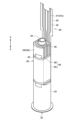
- FIG. 2 is a perspective view schematically showing an example of the heater assembly 10 according to this embodiment.
- FIG. 3 is a diagram schematically showing an example of a cross section of the heater assembly 10 taken along arrow AA.
- FIG. 4 is a perspective view schematically showing an example of the housing section 20 according to the present embodiment.
- FIG. 5 is a developed view of an example of the heating section 40 according to this embodiment.
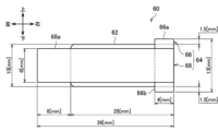
- FIG. 6 is a developed view of an example of the heat diffusion sheet 60 according to this embodiment. Note that the units of dimensions illustrated in FIGS. 5 and 6 are millimeters [mm]. It is assumed that the outer circumferential length of the accommodating portion 20 is 23.3 [mm].
- the height direction of the accommodating portion 20 (in other words, the direction in which the stick-shaped base material 150 is inserted and removed) is also referred to as the up-down direction.
- the direction toward the opening 22 of the accommodating portion 20 is defined as an upward direction, and the direction toward the bottom wall 26 is defined as a downward direction.
- the circumferential direction of the accommodating portion 20 is also referred to as the left-right direction.
- the clockwise direction is defined as the left direction
- the counterclockwise direction is defined as the right direction.
- the heater assembly 10 is one of the components that constitute the suction device 100.
- the heater assembly 10 is a component that is particularly involved in heating the stick-type base material 150.
- the heater assembly 10 includes a housing section 20, a heating section 40, and a heat diffusion sheet 60.
- the heater assembly 10 is constructed by wrapping and arranging the heating section 40 and the heat diffusion sheet 60 around the outer surface of the housing section 20.
- the housing section 20 is a bottomed cylindrical member that includes an opening 22, a side wall 24, and a bottom wall 26 that closes the end opposite to the opening 22.
- a hole (not shown) is provided in the bottom wall 26, and an air flow path 28 having a cylindrical shape is connected thereto.
- the stick-type base material 150 is inserted into the accommodating portion 20 through the opening 22 and is accommodated in the internal space 30 surrounded by the side wall 24 and the bottom wall 26 .
- the accommodating portion 20 is made of a material having a predetermined heat conductivity, such as SUS (Steel Use Stainless). This enables efficient heating of the stick-type base material 150.
- the side wall 24 of the accommodating portion 20 includes two planar portions 24a formed in a planar shape and two curved portions 24b formed in a curved manner.
- the shape of the accommodating portion 20 in a plane perpendicular to the vertical direction may be approximately elliptical.
- the two plane parts 24a may each form a straight line, and the two curved parts 24b may each form a semicircular arc.
- the distance between the inner surfaces of the two flat parts 24a is preferably smaller than the width of the stick-shaped base material 150. In that case, the accommodating part 20 can hold the stick-shaped base material 150 while pressing it with the two flat parts 24a.
- the heating section 40 includes a conductive track 41 and an electrically insulating base material 42.
- the conductive track 41 is a circuit made of a conductive material.
- the electrically insulating base material 42 is a film-like base material made of an insulating material.
- An example of the material having insulation properties is PI (Polyimide).
- the heating section 40 may be constructed by arranging a conductive track 41 on a membrane-like electrically insulating substrate 42 .
- the heating unit 40 may be a film heater configured by sandwiching a conductive track 41 between two electrically insulating base materials 42 configured as PI films.
- Other examples of materials having insulating properties include PET (Polyethylene terephthalate) and fluororesin.
- the conductive track 41 includes a heat generating portion 41a and a non-heat generating portion 41b.
- the heat generating portion 41a is a portion of the conductive track 41 that generates heat when a current is applied.
- the non-heat generating portion 41b is a portion of the conductive track 41 that does not generate heat or generates very little heat even when a current is applied. That is, the electrical resistance of the heat generating portion 41a is higher than the electrical resistance of the non-heat generating portion 41b.
- the heat generating portion 41a may be configured to be thin, and the non-heat generating portion 41b may be configured to be wide. Thereby, the magnitude relationship of the electrical resistance described above can be realized.
- the heat generating portion 41a may be made of, for example, SUS (steel use stainless).
- the non-heat generating portion 41b may be made of a material containing at least one of copper and nickel, for example.
- the non-heat generating portion 41b may be formed by plating SUS with copper and nickel.
- the thickness of SUS may be 30 ⁇ m
- the thickness of nickel may be 30 ⁇ m
- the thickness of copper may be 5 ⁇ m.
- the material constituting the conductive track 41 is not limited to the above example, but may be other materials such as aluminum.
- the heating unit 40 is placed in the housing unit 20 with a part of the outer surface of the housing unit 20 covered and the other part exposed.
- the heating section 40 may be formed in a shape having cutouts 49a and 49b in plan view. In that case, the heating section 40 covers the outer surface of the housing section 20 except for the cutouts 49a and 49b.
- the outer surface of the housing portion 20 is exposed at the cutouts 49a and 49b. According to this configuration, when the outer surface of the accommodating part 20 has irregularities, the heating part 40 comes into close contact with the outer surface of the accommodating part 20 while avoiding the irregularities on the outer surface of the accommodating part 20 by the cutouts 49a and 49b. becomes possible.
- the heating section 40 will float on the uneven portion of the outer surface of the housing section 20, and the temperature of the floating section will rise rapidly, potentially damaging the heating section 40.
- the heating section 40 comes into close contact with the outer surface of the housing section 20, so that it is possible to prevent the heating section 40 from being damaged.
- the electrically insulating base material 42 has cutouts 49a and 49b.
- the conductive track 41 is then placed on the electrically insulating base material 42, avoiding the cutouts 49a and 49b.
- the conductive track 41 is arranged on the electrically insulating base material 42 so as to go around the electrically insulating base material 42 from the lower end, bypassing the cutouts 49a and 49b, and return to the lower end again.
- the conductive track 41 is exposed from the electrically insulating base material 42 at the lower end of the heating section 40 and is electrically connected to the power supply section 111 .
- the conductive track 41 is formed in an M-shape with three folds in the heat generating portion 41a.
- heat generating portions 41a-1 to 41a-4 corresponding to four vertical bars arranged before and after the three folds forming the M-shape are arranged at equal intervals on the outer surface of the housing section 20. They may be spaced apart.
- the number of turns of the conductive track 41 is not limited to three, but may be any number greater than or equal to one.
- the thermal diffusion sheet 60 is constructed by laminating a graphite sheet 62 and a PI tape 64.
- the heat diffusion sheet 60 is an example of a heat diffusion layer formed in a film shape.
- the heat diffusion sheet 60 has a function of diffusing heat.
- the heat diffusion sheet 60 is arranged so as to be wrapped around the outside of the heating section 40, which is arranged around the outer surface of the housing section 20. As shown in FIGS. With this configuration, the heat of the heating section 40 can be diffused throughout the housing section 20. As a result, it becomes possible to efficiently heat the stick-shaped base material 150 housed in the housing section 20.
- the graphite sheet 62 is a sheet-like member made of graphite.
- the graphite sheet 62 is an example of a first layer whose thermal conductivity is greater than or equal to a first threshold value. It is desirable that the thermal conductivity of the graphite sheet 62 is higher than at least the thermal conductivity of the accommodating portion 20.
- An example of the first threshold value is 50 [W/(m ⁇ K)], and more preferably 100 [W/(m ⁇ K)]. Note that it is desirable that the thermal conductivity of the graphite sheet 62 in the plane direction is equal to or higher than the first threshold value, and the thermal conductivity of the graphite sheet 62 in the thickness direction is not particularly limited.
- the graphite sheet 62 has a thickness of 40 [um], a thermal conductivity in the plane direction of 1500 [W/(m ⁇ K)], and a thermal conductivity in the thickness direction of 5 [W/( m ⁇ K)]. According to this configuration, the graphite sheet 62 can efficiently transmit the heat of the heating section 40 to the entire area of the housing section 20.
- the PI tape 64 is a tape made of PI.
- the PI tape 64 is constructed by applying an adhesive to one surface of a film-like member made of PI.
- the PI tape 64 is an example of a second layer whose tensile strength is greater than or equal to the second threshold. It is desirable that the tensile strength of the PI tape 64 is at least higher than the tensile strength of the graphite sheet 62.
- An example of the second threshold value is 60 [MPa] under a normal temperature environment, and more preferably 120 [MPa]. Note that an example of the second threshold value relates to the tensile strength in the longitudinal direction when the PI tape 64 has a width of 25 mm. According to this configuration, the PI tape 64 can prevent the graphite sheet 62 from tearing during assembly.
- the PI tape 64 includes a vertically long PI tape 66 and a horizontally long PI tape 68.
- the vertically elongated PI tape 66 is an example of the first portion of the PI tape 64.
- the horizontally long PI tape 68 is an example of the second portion of the PI tape 64.
- the heat diffusion sheet 60 is constructed by having a graphite sheet 62 as the bottom layer, a vertically long PI tape 66 as the middle layer, and a horizontally long PI tape 68 as the top layer, which are superimposed and adhered.
- the vertically long PI tape 66 and the horizontally long PI tape 68 are stacked on top of each other with their adhesive surfaces facing toward the bottom layer.
- the graphite sheet 62, the vertically long PI tape 66, and the horizontally long PI tape 68 are stacked so that their right ends coincide and their vertical centers coincide. Note that when the heat diffusion sheet 60 is wound around the housing portion 20, the inner layer is the bottom layer, and the outer layer is the uppermost layer.
- the length of the graphite sheet 62 in the vertical direction is 10 mm, and the length in the horizontal direction is 28 mm.
- the length of the vertically long PI tape 66 in the vertical direction is 13 mm, and the length in the horizontal direction is 4 mm.
- the length of the horizontally long PI tape 68 in the vertical direction is 8 mm, and the length in the horizontal direction is 36 mm.
- the heat diffusion sheet 60 is arranged so as to be wrapped around the outside of the heating section 40 disposed on the outer surface of the storage section 20, with the graphite sheet 62 on the inside and the PI tape 64 on the outside. That is, the heating section 40, the graphite sheet 62, and the PI tape 64 are arranged around the outer surface of the housing section 20 in this order. According to this configuration, it becomes possible to bring the graphite sheet 62 into close contact with the heating section 40 or the housing section 20. As a result, it becomes possible to improve the heat diffusion effect from the heating section 40 to the housing section 20 via the graphite sheet 62.
- the graphite sheet 62 is formed longer than the outer circumferential length of the accommodating portion 20 in the left-right direction. Specifically, the length of the graphite sheet 62 in the left-right direction is 28 [mm], and the outer circumferential length of the accommodating portion 20 is 23.3 [mm]. As a result, as shown in FIG. 3, the graphite sheet 62 is wrapped around the outer surface of the accommodating portion 20 one or more times. According to this configuration, the graphite sheet 62 completely covers the outer periphery of the accommodating part 20, making it possible to diffuse the heat of the heating part 40 to the entire outer periphery of the accommodating part 20.
- the horizontally long PI tape 68 is formed to be longer than the outer circumferential length of the accommodating portion 20 in the left-right direction. Specifically, the length of the horizontally long PI tape 68 in the left-right direction is 36 [mm], and the outer circumferential length of the accommodating portion 20 is 23.3 [mm]. According to this configuration, the graphite sheet 62 can be more firmly fixed by wrapping the horizontally long PI tape 68 around the accommodating portion 20 one turn or more.
- the PI tape 64 (particularly the horizontally long PI tape 68) is formed longer than the graphite sheet 62 in the left-right direction. Specifically, the length of the horizontally long PI tape 68 in the left-right direction is 36 [mm], and the length of the graphite sheet 62 in the left-right direction is 28 [mm].
- the heat diffusion sheet 60 is formed by bonding the graphite sheet 62 and the PI tape 64 so that the PI tape 64 (in particular, the horizontally long PI tape 68) covers the entire graphite sheet 62 in the left and right direction.
- the heat diffusion sheet 60 is wound around the outer surface of the storage section 20 by rotating the storage section 20 while pressing the heat diffusion sheet 60 against the storage section 20 using a rubber roller or the like.
- the rubber roller when winding the heat diffusion sheet 60 around the storage portion 20, the rubber roller can be brought into contact only with the PI tape 64 and not with the graphite sheet 62. This makes it possible to reduce the force applied to the graphite sheet 62 and prevent the graphite sheet 62 from breaking.
- the horizontally long PI tape 68 is provided with a protruding portion 68a that protrudes from the graphite sheet 62 in the left-right direction.
- the protruding portion 68a is adhered to the PI tape 64 (particularly the horizontally long PI tape 68) that is wound one round inside the protruding portion 68a.
- the position of the graphite sheet 62 can be fixed by the horizontally long PI tape 68.
- the horizontally long PI tape 68 may be formed shorter than the graphite sheet 62 in the vertical direction.
- the length of the horizontally long PI tape 68 in the vertical direction is 8 [mm]
- the length of the graphite sheet 62 in the vertical direction is 10 [mm].
- the vertically long PI tape 66 is formed longer than the graphite sheet 62 in the vertical direction. Specifically, the length of the vertically long PI tape 66 in the vertical direction is 13 [mm], and the length of the graphite sheet 62 in the vertical direction is 10 [mm]. Therefore, both end portions 66a and 66b of the vertically long PI tape 66 in the vertical direction protrude from the graphite sheet 62 in the vertical direction. Specifically, both end portions 66a and 66b of the vertically long PI tape 66 protrude from the graphite sheet 62 by 1.5 mm in the vertical direction.
- both end portions 66 a and 66 b of the vertically long PI tape 66 that protrude from the graphite sheet 62 in the vertical direction are adhered to the heating section 40 . According to this configuration, it is possible to fix the heat diffusion sheet 60 to the heating section 40 and prevent misalignment between the heating section 40 and the heat diffusion sheet 60.
- the heating part 40 has blank areas 43a and 43b where the conductive track 41 is not arranged, which are vertically adjacent to the part where the heat generating part 41a is arranged.
- the blank areas 43a and 43b are areas consisting only of the electrically insulating base material 42.
- both end portions 66a and 66b in the vertical direction of the vertically long PI tape 66 are adhered to the blank areas 43a and 43b of the heating section 40.
- the heat diffusion sheet 60 can be more firmly fixed to the heating section 40.
- the size of the region of the heating unit 40 where the heat generating portion 41a is arranged is 20.75 [mm] in the left-right direction and 10 [mm] in the vertical direction.
- the blank areas 43a and 43b of the heating section 40 are configured to have positions and sizes corresponding to both end portions 66a and 66b of the vertically long PI tape 66.
- a blank area 43a having a size of 1.5 [mm] in the vertical direction and 6.1 [mm] in the horizontal direction is provided above the region of the heating unit 40 where the heat generating portion 41a is arranged. provided.
- a margin area 43b having a size of 1.5 [mm] in the vertical direction and 6.1 [mm] in the horizontal direction is provided below the region of the heating section 40 where the heat generating part 41a is arranged. .
- the blank area 43a and the blank area 43b of the heating unit 40 are provided so as to be separated by 10 mm in the vertical direction.
- the length from the top end to the bottom end of the margin areas 43a and 43b is 13 [mm], which is the same as the length in the vertical direction of the vertically long PI tape 66, and the length from the left end to the right end of the margin areas 43a and 43b is 13 [mm].
- the length is 6.1 mm, which is longer than the length of the tape 66 in the left-right direction.
- a graphite sheet 62 that also has a length of 10 [mm] in the vertical direction is wrapped around a region of the heating unit 40 that has a length of 10 [mm] in the vertical direction, where the heat generating portion 41a is arranged. becomes possible. According to this configuration, the portion of the heating section 40 where the heat generating portion 41a is arranged is completely covered with the graphite sheet 62, and the heat of the heating section 40 can be efficiently diffused.
- FIG. 7 is a flowchart illustrating an example of a method for manufacturing the heater assembly 10 according to this embodiment.
- FIG. 8 is a diagram schematically showing an example of a method for manufacturing the heater assembly 10 according to the present embodiment.
- the manufacturing method described below with reference to FIGS. 7 and 8 is executed by, for example, a machine tool.
- the machine tool includes a belt conveyor that conveys various parts, an arm that grips and operates various parts, a rotating machine that rotates the housing part 20, and a heating unit 40 and a heat diffusion sheet 60 on the outer surface of the rotating housing part 20. It may have a rubber roller or the like that adheres while pressing.
- the machine tool first generates the thermal diffusion sheet 60 by laminating and bonding the graphite sheet 62, the vertically long PI tape 66, and the horizontally long PI tape 68 (step S102).
- the machine tool adheres the thermal diffusion sheet 60 to the heating section 40 with the graphite sheet 62 on the inside (step S104).
- the machine tool adheres both vertically end portions 66a and 66b of the vertically long PI tape 66 to the blank areas 43a and 43b of the heating section 40.
- the machine tool places the bonded heating unit 40 and thermal diffusion sheet 60 around the outer surface of the storage unit 20, with the heating unit 40 on the inside (step S106). Specifically, first, as shown in FIG. 8, the machine tool attaches a portion of the bonded heating section 40 and heat diffusion sheet 60 that corresponds to the vertically long PI tape 66 to the flat section 24a of the accommodating section 20. Next, as shown in FIG. 8, the machine tool rotates the housing section 20 by 100 degrees to the left, and then by 640 degrees to the right. At this time, the machine tool rotates the housing section 20 while pressing the heating section 40 and the heat diffusion sheet 60 against the outer surface of the housing section 20 using a rubber roller. Thereby, the heating section 40 and the heat diffusion sheet 60 can be suitably adhered to the outer surface of the housing section 20.
- FIG. 9 is a diagram schematically showing an example of a cross section of the heater assembly 10 according to the first supplement.
- the heater assembly 10 may include a heat insulating part 70 and a heat shrink tube 80 in addition to the housing part 20, the heating part 40, and the heat diffusion sheet 60.
- the heater assembly 10 shown in FIG. 9 has a heating section 40 and a heat diffusion sheet 60 wrapped around the outer surface of the housing section 20, and a heat insulating section 70 and a heat shrink tube 80 wrapped around the outer side of the heating section 40 and a heat diffusion sheet 60. , configured.
- the heat insulating section 70 is constructed by laminating a heat insulating sheet 71 and a PI tape 72.
- the heat insulating sheet 71 is an example of a heat insulating layer whose thermal conductivity is less than the third threshold value. It is desirable that the thermal conductivity of the heat insulating sheet 71 is at least lower than that of the PI tape 64.
- An example of the third threshold is 1 [W/mK], and more preferably 0.5 [W/mK].
- the heat insulating sheet 71 is made of a glass material, a vacuum heat insulating material, an airgel heat insulating material, or the like.
- the heat insulating sheet 71 may be an airgel sheet made of an airgel heat insulating material and having a thermal conductivity of 0.02 [W/mK].
- the PI tape 72 is a tape made of PI.
- the PI tape 72 is constructed by applying an adhesive to one surface of a film-like member made of PI.
- the heat insulating section 70 is arranged so as to be wrapped further outside the heating section 40 and the heat diffusion sheet 60 that are wrapped around the outer surface of the housing section 20.
- the heat insulating section 70 is wound with the heat insulating sheet 71 on the inside and the PI tape 72 on the outside, with the adhesive surface of the PI tape 72 facing inward.
- the PI tape 72 is formed longer than the heat insulating sheet 71 in the left-right direction. Then, a protruding portion 72a of the PI tape 72 that protrudes from the heat insulating sheet 71 in the left-right direction is adhered to the PI tape 72 that is wound one round inside the protruding portion 72a of the PI tape 72.
- the PI tape 72 can fix the heat insulating sheet 71.
- the outer periphery of the heat diffusion sheet 60 can be completely covered by the heat insulating part 70.
- the heat shrink tube 80 is a tubular member that shrinks when heat is applied.
- the heating section 40 and the heat diffusion sheet 60 are wrapped around the outer surface of the housing section 20 and fixed to the housing section 20 with a heat shrink tube 80 while being covered by the heat insulating section 70 .
- the heat shrink tube 80 is made of a resin material.
- the heating unit 40 is attached to the outer surface of the accommodating portion 20 in a state where a part of the outer surface of the accommodating portion 20 is covered and the other part is exposed. Placed.
- the shape of the heating part 40 for realizing such a configuration is not formed in a shape having notches 49a and 49b in plan view.
- the heating section 40 may be formed in a T-shape in plan view.
- FIGS. 10 to 12 an example in which the heating section 40 is formed in a T-shape will be described with reference to FIGS. 10 to 12.
- FIG. 10 is a perspective view schematically showing an example of the heater assembly 10 according to the second supplement.
- FIG. 11 is a perspective view showing an example of the state before the heating unit 40 according to the second supplement is arranged on the outer surface of the housing unit 20.
- FIG. 12 is a perspective view showing an example of the state after the heating part 40 according to the second supplement is arranged on the outer surface of the housing part 20.
- the heater assembly 10 includes a housing section 20, a heating section 40, and a heat diffusion sheet 60.
- the heater assembly 10 is configured by arranging the heating section 40 and the heat diffusion sheet 60 on the outer surface of the housing section 20.
- the configuration of the accommodating portion 20 is as described in the above embodiment. However, as shown in FIGS. 10 to 12, the flat part 24a of the accommodating part 20 is formed only on a lower part of the side wall 24, and the side wall 24 above the flat part 24a may be curved. good.
- the heating section 40 has a T-shape in plan view before being bent.
- the T-shaped horizontal bar portion 44 of the heating section 40 is bent along the outer surface of the housing section 20 and arranged along the outer surface of the housing section 20 .
- the T-shaped vertical bar portion 45 of the heating portion 40 is bent in the opposite direction to the T-shaped horizontal bar portion 44, and is separated from the outer surface of the housing portion 20.
- the heating section 40 is provided with a hole 46. More specifically, a hole 46 is provided in the center of the T-shape before bending.
- the conductive track 41 starts from the end of the T-shaped vertical bar portion 45 of the heating unit 40, goes around the T-shaped horizontal bar portion 44 while bypassing the hole 46, and goes around the T-shaped horizontal bar portion 44 to the end of the T-shaped vertical bar portion 45. It is arranged so that it will come back to the department again.
- the heating unit 40 is arranged around the housing unit 20 with the air flow path 28 provided in the bottom wall 26 of the housing unit 20 passing through the hole 46 of the heating unit 40.
- the holes 46 of the heating section 40 circumscribe the air flow path 28 . With this configuration, it is possible to prevent the heating unit 40 from shifting.
- the heating section 40 is bent at a T-shaped horizontal bar section 44 and arranged along the bottom wall 26 and the flat section 24a of the accommodating section 20.
- the two flat parts 24a are provided at positions facing each other, and the T-shaped horizontal bar part 44 of the heating part 40 is arranged along each of these two facing flat parts 24a.
- the heating section 40 is fixed so as to sandwich the housing section 20 from the outside of the opposing flat section 24a. This makes it possible to prevent the heating unit 40 from shifting.
- the configuration of the heat diffusion sheet 60 is as described in the above embodiment.
- the heat diffusion sheet 60 is arranged so as to be wrapped around the housing section 20 in which the heating section 40 is arranged, with the graphite sheet 62 inside.
- the heat diffusion sheet 60 is arranged so as to be wrapped around the outer surface of the accommodating part 20 so as to cover the T-shaped horizontal bar part 44 of the heating part 40 arranged on the flat surface 24a of the accommodating part 20.
- a vertically long PI tape 66 is adhered to the curved portion 24b of the housing portion 20.
- the vertically long PI tape 66 may be adhered to the heating section 40 disposed on the flat section 24a of the housing section 20.
- the graphite sheet 62 made of graphite was cited as an example of the first layer making up the heat diffusion sheet 60, but the present invention is not limited to this example.
- the first layer constituting the heat diffusion sheet 60 may be composed of one or more materials selected from a group of materials including copper, graphite, aluminum, and the like.
- the PI tape 64 made of PI was cited as an example of the second layer making up the heat diffusion sheet 60, but the present invention is not limited to such an example.
- the second layer constituting the heat diffusion sheet 60 may be made of one or more materials selected from a group of materials including PI, silica, polyester, glass cloth, and the like.
- the heat diffusion sheet 60 is configured such that the bottom layer is a graphite sheet 62, the middle layer is a vertically long PI tape 66, and the top layer is a horizontally long PI tape 68, which are bonded in an overlapping state.
- the present invention is not limited to such examples.
- the adhesion order of the vertically long PI tape 66 and the horizontally long PI tape 68 may be reversed.
- each device described in this specification may be realized using software, hardware, or a combination of software and hardware.
- a program constituting the software is stored in advance, for example, in a recording medium (specifically, a computer-readable non-temporary storage medium) provided inside or outside each device.
- each program is read into the RAM when executed by a computer that controls each device described in this specification, and is executed by a processing circuit such as a CPU.
- the recording medium is, for example, a magnetic disk, an optical disk, a magneto-optical disk, a flash memory, or the like.
- the above computer program may be distributed, for example, via a network, without using a recording medium.
- the above-mentioned computer may be an application-specific integrated circuit such as an ASIC, a general-purpose processor that executes functions by loading a software program, or a computer on a server used for cloud computing. Furthermore, a series of processes performed by each device described in this specification may be distributed and processed by multiple computers.
- a cylindrical member having an opening into which an aerosol generating article containing an aerosol source can be inserted; a membrane-shaped heating section disposed on the outer surface of the cylindrical member; a thermal diffusion layer in which a first layer having a thermal conductivity equal to or higher than a first threshold value and a second layer having a tensile strength equal to or higher than a second threshold value are laminated; Equipped with The heat diffusion layer is arranged so as to wrap around the outside of the heating section disposed on the outer surface of the cylindrical member, with the first layer on the inside and the second layer on the outside. Aerosol generation system.
- the second layer is formed longer than the first layer in the circumferential direction of the cylindrical member,
- the heat diffusion layer is formed by adhering the first layer and the second layer so that the second layer covers the first layer over the entire circumferential direction of the cylindrical member.
- Ru The aerosol generation system according to (1) above.
- the second layer includes a first portion that is longer than the first layer in the height direction of the cylindrical member, Of the first portion of the second layer, both end portions protruding from the first layer in the height direction of the cylindrical member are bonded to the heating section.
- the heating section is a membrane-like electrically insulating base material; a conductive track disposed on the electrically insulating substrate; including; The both end portions of the first portion of the second layer are located at a height of the cylindrical member and a portion of the heating portion where a heating portion of the conductive track that generates heat when a current is applied is disposed. Adhering to a blank area adjacent in the width direction where the conductive track is not placed; The aerosol generation system according to (3) above.
- the second layer includes a second portion whose length in the circumferential direction of the cylindrical member is longer than the outer circumferential length of the cylindrical member, Among the second portions of the second layer, a protruding portion that protrudes from the first layer in the circumferential direction of the cylindrical member is a portion of the second layer that is wound one circumference inward from the protruding portion. glued to, The aerosol generation system according to any one of (1) to (4) above. (6) The second portion of the second layer is formed shorter than the first layer in the height direction of the cylindrical member. The aerosol generation system according to (5) above. (7) The first layer is formed to be longer than the outer circumferential length of the cylindrical member in the circumferential direction of the cylindrical member.
- the heating section is a membrane-like electrically insulating base material; a conductive track disposed on the electrically insulating substrate; including;
- the heating part is arranged on the outer surface of the cylindrical member, with a part of the outer surface of the cylindrical member covered and another part exposed.
- the heating part is formed in a T-shape or a shape having a notch in a plan view.
- the aerosol generation system includes: a heat insulating layer whose thermal conductivity is less than a third threshold; heat shrink tubing that shrinks when heated; Equipped with The heating part and the heat diffusion layer are wrapped around the outer surface of the cylindrical member and fixed to the cylindrical member with a heat shrink tube while being covered with the heat insulating layer.
- the aerosol generation system according to any one of (1) to (9) above.
- the first layer is formed of copper, graphite, or aluminum.
- the second layer is formed of PI (Polyimide).
- the cylindrical member is formed of SUS (steel use stainless).
- a heat diffusion layer in which a first layer having a thermal conductivity equal to or higher than a first threshold value and a second layer having a tensile strength equal to or higher than a second threshold value are laminated is formed into a film shape with the first layer inside. Adhering to the heating part of the arranging the bonded heating section and the thermal diffusion layer on the outer surface of a cylindrical member having an opening into which an aerosol generating article containing an aerosol source can be inserted, with the heating section inside;
- a method of manufacturing an aerosol generation system comprising:
- Suction device 111 Power supply section 112 Sensor section 113 Notification section 114 Storage section 115 Communication section 116 Control section 150 Stick type base material 151 Base material section 152 Sucking section 10 Heater assembly 20 Accommodation section 22 Opening 24 Side wall (24a: flat section, 24b : curved part) 26 Bottom wall 28 Air flow path 30 Internal space 40 Heating part 41 Conductive track (41a: heat generating part, 41b: non-heat generating part) 42 Electrical insulation base material 43a, 43b Margin area 60 Heat diffusion sheet 62 Graphite sheet 64 PI tape 66 Vertical PI tape (66a, 66b: both end portions) 68 Horizontal PI tape (68a: protruding part) 70 Heat insulation part 71 Heat insulation sheet 71 Heat insulation sheet 72 PI tape (72a: protruding part) 80 Heat shrink tube
Landscapes
- Resistance Heating (AREA)
Priority Applications (6)
| Application Number | Priority Date | Filing Date | Title |
|---|---|---|---|
| PCT/JP2022/020019 WO2023218586A1 (ja) | 2022-05-12 | 2022-05-12 | エアロゾル生成システム、及びエアロゾル生成システムの製造方法 |
| EP22941666.4A EP4523555A4 (en) | 2022-05-12 | 2022-05-12 | Aerosol generating system and method for producing aerosol generating system |
| JP2024520167A JP7741977B2 (ja) | 2022-05-12 | 2022-05-12 | エアロゾル生成システム、及びエアロゾル生成システムの製造方法 |
| CN202280095993.8A CN119095506A (zh) | 2022-05-12 | 2022-05-12 | 气溶胶生成系统及气溶胶生成系统的制造方法 |
| KR1020247040499A KR20250006299A (ko) | 2022-05-12 | 2022-05-12 | 에어로졸 생성 시스템, 및 에어로졸 생성 시스템의 제조 방법 |
| US18/932,676 US20250049130A1 (en) | 2022-05-12 | 2024-10-31 | Aerosol generating system and method for producing aerosol generating system |
Applications Claiming Priority (1)
| Application Number | Priority Date | Filing Date | Title |
|---|---|---|---|
| PCT/JP2022/020019 WO2023218586A1 (ja) | 2022-05-12 | 2022-05-12 | エアロゾル生成システム、及びエアロゾル生成システムの製造方法 |
Related Child Applications (1)
| Application Number | Title | Priority Date | Filing Date |
|---|---|---|---|
| US18/932,676 Continuation US20250049130A1 (en) | 2022-05-12 | 2024-10-31 | Aerosol generating system and method for producing aerosol generating system |
Publications (1)
| Publication Number | Publication Date |
|---|---|
| WO2023218586A1 true WO2023218586A1 (ja) | 2023-11-16 |
Family
ID=88730136
Family Applications (1)
| Application Number | Title | Priority Date | Filing Date |
|---|---|---|---|
| PCT/JP2022/020019 Ceased WO2023218586A1 (ja) | 2022-05-12 | 2022-05-12 | エアロゾル生成システム、及びエアロゾル生成システムの製造方法 |
Country Status (6)
| Country | Link |
|---|---|
| US (1) | US20250049130A1 (https=) |
| EP (1) | EP4523555A4 (https=) |
| JP (1) | JP7741977B2 (https=) |
| KR (1) | KR20250006299A (https=) |
| CN (1) | CN119095506A (https=) |
| WO (1) | WO2023218586A1 (https=) |
Citations (6)
| Publication number | Priority date | Publication date | Assignee | Title |
|---|---|---|---|---|
| JPH08135888A (ja) * | 1994-11-07 | 1996-05-31 | Sekisui Chem Co Ltd | 断熱保温テープ |
| JP6210610B2 (ja) | 2009-10-29 | 2017-10-11 | フィリップ・モーリス・プロダクツ・ソシエテ・アノニム | 加熱器が改善された電気加熱式喫煙システム |
| WO2019208536A1 (ja) * | 2018-04-26 | 2019-10-31 | 日本たばこ産業株式会社 | ヒータアッセンブリ及び容器 |
| WO2020084759A1 (ja) * | 2018-10-26 | 2020-04-30 | 日本たばこ産業株式会社 | 筐体およびこれを備えた香味吸引器 |
| JP2020527955A (ja) * | 2017-07-21 | 2020-09-17 | アモセンス・カンパニー・リミテッドAmosense Co., Ltd. | 巻きタバコ型電子タバコ用ヒーター組立体およびこれを含む巻きタバコ型電子タバコ |
| JP2022504402A (ja) * | 2018-10-12 | 2022-01-13 | ジェイティー インターナショナル エス.エイ. | エアロゾル発生装置及びそのための加熱チャンバ |
Family Cites Families (2)
| Publication number | Priority date | Publication date | Assignee | Title |
|---|---|---|---|---|
| JPS6210610U (https=) | 1985-07-05 | 1987-01-22 | ||
| WO2022090156A1 (en) * | 2020-10-28 | 2022-05-05 | Philip Morris Products S.A. | Heater tube with thermal insulation and electrical isolation |
-
2022
- 2022-05-12 JP JP2024520167A patent/JP7741977B2/ja active Active
- 2022-05-12 KR KR1020247040499A patent/KR20250006299A/ko active Pending
- 2022-05-12 EP EP22941666.4A patent/EP4523555A4/en active Pending
- 2022-05-12 CN CN202280095993.8A patent/CN119095506A/zh active Pending
- 2022-05-12 WO PCT/JP2022/020019 patent/WO2023218586A1/ja not_active Ceased
-
2024
- 2024-10-31 US US18/932,676 patent/US20250049130A1/en active Pending
Patent Citations (6)
| Publication number | Priority date | Publication date | Assignee | Title |
|---|---|---|---|---|
| JPH08135888A (ja) * | 1994-11-07 | 1996-05-31 | Sekisui Chem Co Ltd | 断熱保温テープ |
| JP6210610B2 (ja) | 2009-10-29 | 2017-10-11 | フィリップ・モーリス・プロダクツ・ソシエテ・アノニム | 加熱器が改善された電気加熱式喫煙システム |
| JP2020527955A (ja) * | 2017-07-21 | 2020-09-17 | アモセンス・カンパニー・リミテッドAmosense Co., Ltd. | 巻きタバコ型電子タバコ用ヒーター組立体およびこれを含む巻きタバコ型電子タバコ |
| WO2019208536A1 (ja) * | 2018-04-26 | 2019-10-31 | 日本たばこ産業株式会社 | ヒータアッセンブリ及び容器 |
| JP2022504402A (ja) * | 2018-10-12 | 2022-01-13 | ジェイティー インターナショナル エス.エイ. | エアロゾル発生装置及びそのための加熱チャンバ |
| WO2020084759A1 (ja) * | 2018-10-26 | 2020-04-30 | 日本たばこ産業株式会社 | 筐体およびこれを備えた香味吸引器 |
Non-Patent Citations (1)
| Title |
|---|
| See also references of EP4523555A4 |
Also Published As
| Publication number | Publication date |
|---|---|
| EP4523555A4 (en) | 2026-03-04 |
| US20250049130A1 (en) | 2025-02-13 |
| JP7741977B2 (ja) | 2025-09-18 |
| CN119095506A (zh) | 2024-12-06 |
| EP4523555A1 (en) | 2025-03-19 |
| JPWO2023218586A1 (https=) | 2023-11-16 |
| KR20250006299A (ko) | 2025-01-10 |
Similar Documents
| Publication | Publication Date | Title |
|---|---|---|
| JP7595173B2 (ja) | エアロゾル生成システム | |
| JP2023161044A (ja) | エアロゾル生成システム、及びエアロゾル生成システムの製造方法 | |
| WO2023218586A1 (ja) | エアロゾル生成システム、及びエアロゾル生成システムの製造方法 | |
| JP7832353B2 (ja) | エアロゾル生成システム | |
| JP7746408B2 (ja) | エアロゾル生成システム | |
| JP7830676B2 (ja) | エアロゾル生成システム | |
| JP7830677B2 (ja) | エアロゾル生成システム | |
| JP7832352B2 (ja) | エアロゾル生成システム | |
| JP7656078B2 (ja) | エアロゾル生成システム | |
| JP7683038B2 (ja) | エアロゾル生成システム | |
| WO2022230009A1 (ja) | 香味吸引器 | |
| WO2022264312A1 (ja) | エアロゾル生成システム | |
| WO2025104791A1 (ja) | 吸引装置 | |
| JP7634097B2 (ja) | 香味吸引器及びヒータの製造方法 | |
| WO2025262864A1 (ja) | エアロゾル生成装置及びエアロゾル生成装置の製造方法 | |
| WO2024004214A1 (ja) | エアロゾル生成装置、及びエアロゾル生成システム | |
| WO2024004213A1 (ja) | エアロゾル生成装置、及びエアロゾル生成システム | |
| WO2025134254A1 (ja) | 吸引装置 | |
| WO2023127048A1 (ja) | 非燃焼型香味吸引器の本体ユニット及び非燃焼型香味吸引器 | |
| WO2026088377A1 (ja) | ヒータアセンブリ | |
| WO2024105820A1 (ja) | エアロゾル生成システム、制御方法及びプログラム | |
| WO2024201943A1 (ja) | エアロゾル生成装置の電源ユニット、及びエアロゾル生成装置 |
Legal Events
| Date | Code | Title | Description |
|---|---|---|---|
| 121 | Ep: the epo has been informed by wipo that ep was designated in this application |
Ref document number: 22941666 Country of ref document: EP Kind code of ref document: A1 |
|
| ENP | Entry into the national phase |
Ref document number: 2024520167 Country of ref document: JP Kind code of ref document: A |
|
| WWE | Wipo information: entry into national phase |
Ref document number: 202280095993.8 Country of ref document: CN |
|
| ENP | Entry into the national phase |
Ref document number: 20247040499 Country of ref document: KR Kind code of ref document: A |
|
| WWE | Wipo information: entry into national phase |
Ref document number: 1020247040499 Country of ref document: KR |
|
| WWE | Wipo information: entry into national phase |
Ref document number: 2022941666 Country of ref document: EP |
|
| NENP | Non-entry into the national phase |
Ref country code: DE |
|
| ENP | Entry into the national phase |
Ref document number: 2022941666 Country of ref document: EP Effective date: 20241210 |