WO2023218563A1 - 除湿機 - Google Patents
除湿機 Download PDFInfo
- Publication number
- WO2023218563A1 WO2023218563A1 PCT/JP2022/019960 JP2022019960W WO2023218563A1 WO 2023218563 A1 WO2023218563 A1 WO 2023218563A1 JP 2022019960 W JP2022019960 W JP 2022019960W WO 2023218563 A1 WO2023218563 A1 WO 2023218563A1
- Authority
- WO
- WIPO (PCT)
- Prior art keywords
- air
- shutter
- air passage
- dehumidifier
- shielding wall
- Prior art date
- Legal status (The legal status is an assumption and is not a legal conclusion. Google has not performed a legal analysis and makes no representation as to the accuracy of the status listed.)
- Ceased
Links
Images


Classifications
-
- F—MECHANICAL ENGINEERING; LIGHTING; HEATING; WEAPONS; BLASTING
- F24—HEATING; RANGES; VENTILATING
- F24F—AIR-CONDITIONING; AIR-HUMIDIFICATION; VENTILATION; USE OF AIR CURRENTS FOR SCREENING
- F24F1/00—Room units for air-conditioning, e.g. separate or self-contained units or units receiving primary air from a central station
- F24F1/02—Self-contained room units for air-conditioning, i.e. with all apparatus for treatment installed in a common casing
- F24F1/0328—Self-contained room units for air-conditioning, i.e. with all apparatus for treatment installed in a common casing with means for purifying supplied air
-
- F—MECHANICAL ENGINEERING; LIGHTING; HEATING; WEAPONS; BLASTING
- F24—HEATING; RANGES; VENTILATING
- F24F—AIR-CONDITIONING; AIR-HUMIDIFICATION; VENTILATION; USE OF AIR CURRENTS FOR SCREENING
- F24F1/00—Room units for air-conditioning, e.g. separate or self-contained units or units receiving primary air from a central station
- F24F1/02—Self-contained room units for air-conditioning, i.e. with all apparatus for treatment installed in a common casing
- F24F1/0358—Self-contained room units for air-conditioning, i.e. with all apparatus for treatment installed in a common casing with dehumidification means
Definitions
- the present disclosure relates to a dehumidifier.
- FIG. 16 is a vertical cross-sectional view showing a conventional dehumidifier 100A disclosed in Patent Document 1.
- the dehumidifier 100A includes an air intake port 101 and a heat exchanger 102 as a dehumidifying means.
- a filter 104 as an air purifying means and an intake grid 105 that partitions the air passage 103 on the downstream side of the filter 104 and the heat exchanger 102 are arranged in the air passage 103 leading from the intake port 101 to the heat exchanger 102. has been done.
- the filter 104 is arranged so as not to partially cover the heat exchanger 102. Therefore, a part of the airflow generated by the blowing means 106 reaches the heat exchanger 102 without passing through the filter 104.
- a shutter 107 that can open and close the air passage 103a by sliding vertically is provided in the air passage 103a where the filter 104 is not placed.
- the shutter 107 is provided with a handle 108, which allows the user to manually slide the shutter 107.
- a handle 108 which allows the user to manually slide the shutter 107.
- the shutter 107 is slid downward to open the air passage 103a, a large amount of airflow is taken into the heat exchanger 102, so that the operation focuses on dehumidification.
- the shutter 107 is slid upward to close the air passage 103a, most of the airflow passes through the filter 104 and is purified, and the purified airflow is taken into the heat exchanger 102, so that emphasis is placed on air purification. You will have to drive with a certain amount of time.
- the dehumidifier 100A is configured to be switchable between an operation focused on dehumidification and an operation focused on air purification by the user's operation of the shutter 107.
- Patent Document 1 describes that a blind type shutter that can be opened and closed by rotational movement is used as the shutter.
- the dehumidifier 100B includes a blind type shutter 109 that can open and close the air passage 103a in which the filter 104 is not disposed.
- This shutter 109 may be formed into a vertically elongated plate shape.
- a rotation shaft 110a of a motor 110 is connected to an end of the shutter 109 in the width direction, which is arranged at a position that does not interfere with the rotation locus of the shutter 109.
- the shutter 109 can be rotated about the rotating shaft 110a between a closed position shown by a virtual line and an open position where the air passage 103a is opened.
- the motor 110 When the dehumidifier 100B operates with emphasis on air purification, the motor 110 is driven to rotate the shutter 109 to the closed position.
- the air passage 103a on the downstream side of the shutter 109 responds to the pressure of the airflow on the upstream side of the shutter 109 (hereinafter referred to as "external pressure").
- the pressure becomes negative. Therefore, a unidirectional rotational force Pr that attempts to rotate the shutter 109 from the closed position to the open position acts on the shutter 109 in accordance with the pressure difference between the outside air pressure and the negative pressure.
- the rotational force Pr acting on the shutter 109 increases in proportion to the differential pressure, and is particularly noticeable when the amount of air blown is large. Then, when the rotational force Pr acting on the shutter 109 becomes larger than the holding torque of the motor 110, the shutter 109 moves in the opening direction and a gap Gp is generated between the shutter 109 and the filter 104. There is a problem in that air leakage through the gap Gp reduces air cleaning performance and generates gap noise.
- An object of the present invention is to provide a dehumidifier that can prevent a decrease in air purification performance and generation of crackling noise even if differential pressure acts on the shutter that is closed when operating with emphasis on air purification. It is to be.
- a dehumidifier includes a casing having an air intake port and an air outlet, an air blower disposed inside the casing and generating an airflow from the air intake port to the air outlet, and an air blowing means arranged inside the casing, an air purifying means disposed inside the casing; a dehumidifying means disposed inside the casing for removing moisture from the air flow; A second air path in which the air flow reaches the dehumidifying means without passing through the air purifying means, and an opening/closing means for opening and closing the second air path.
- the opening/closing means is arranged around a rotating shaft that is arranged inside the second air passage and extends in the vertical direction, and has a closed position that blocks the second air passage and an open position that opens the second air passage.
- the shutter is rotatable between positions, and the rotation shaft is disposed inside the left and right ends of the shutter perpendicular to the vertical direction in the closed position.
- the rotation axis is arranged inside the left and right ends of the shutter in the closed position where the second air passage is closed, there is a difference between the upstream side and the downstream side of the shutter in the closed position. Even if pressure is generated, rotation forces in two different directions act around the rotation axis. The rotational forces in these two directions cancel each other out, and the rotational force after cancellation is suppressed to be smaller than the holding torque of the motor that rotates the shutter, so that the shutter is prevented from moving in the opening direction. Therefore, it is possible to prevent deterioration in air cleaning performance and generation of crevice noise.
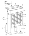
- FIG. 1 is a perspective view of the dehumidifier according to Embodiment 1 seen from the front side.
- 1 is a perspective view of the dehumidifier according to Embodiment 1 seen from the rear side.
- 1 is an exploded perspective view of a dehumidifier according to Embodiment 1.
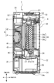
- FIG. FIG. 2 is an exploded perspective view of the vicinity of the intake port of the dehumidifier according to the first embodiment. 2 is a longitudinal cross-sectional view of the dehumidifier according to Embodiment 1 taken along line AA in FIG. 1.
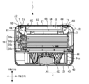
- FIG. 2 is a cross-sectional view of the dehumidifier according to Embodiment 1 taken along line BB in FIG. 1.
- FIG. 2 is a perspective view showing the dehumidifier according to the first embodiment with the case removed.
- FIG. 2 is a partial detailed diagram of the dehumidifier according to the first embodiment.
- 1 is an exploded perspective view of a part of the dehumidifier according to Embodiment 1.
- FIG. FIG. 2 is an exploded perspective view of the shutter of the dehumidifier according to the first embodiment.
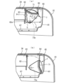
- (a) is a cross-sectional view showing the dehumidifier according to Embodiment 1 with the shutter closing the second air passage
- (b) is a cross-sectional view showing the shutter opening the second air passage.
- FIG. 3 is a cross-sectional view showing the state.
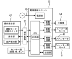
- FIG. 3 is a control block diagram of the dehumidifier according to the first embodiment.
- FIG. 3 is a flowchart diagram showing an example of the operation of the dehumidifier according to the first embodiment.
- (a) is a cross-sectional view showing the dehumidifier according to Embodiment 2 with the shutter closing the second air passage
- (b) is a cross-sectional view showing the shutter opening the second air passage. It is a cross-sectional view shown in a state.
- FIG. 7 is a longitudinal cross-sectional view showing a shutter mounting structure in a dehumidifier according to Embodiment 3
- FIG. 2 is a vertical cross-sectional view of a conventional dehumidifier. It is a structural diagram which operates the shutter of a dehumidifier with a stepping motor.
- FIG. 1 is a perspective view of a dehumidifier 1 according to the first embodiment, viewed from the front side.
- FIG. 2 is a perspective view of the dehumidifier 1 seen from the rear side.
- FIG. 3 is an exploded perspective view of the dehumidifier 1.
- FIG. 4 is an exploded perspective view of the vicinity of the intake port of the dehumidifier 1.
- 5 is a longitudinal cross-sectional view of the dehumidifier 1 taken along the line AA in FIG. 1
- FIG. 6 is a cross-sectional view of the dehumidifier 1 taken along the line BB in FIG.
- the AA line and the BB line pass through the rotation center of a sirocco fan 42, which will be described later.
- FIG. 1 is a perspective view of a dehumidifier 1 according to the first embodiment, viewed from the front side.
- FIG. 2 is a perspective view of the dehumidifier 1 seen from the rear side.
- FIG. 3 is an
- FIG. 7 is a perspective view showing the dehumidifier 1 with the case removed.
- FIG. 8 is a detailed view showing a portion Q surrounded by a broken line in FIG. 5, and
- FIG. 9 is an exploded perspective view of the heat exchanger 38 and heat exchanger retainer 26 shown in FIG.
- the front-rear direction of the dehumidifier 1 is the X-axis direction
- the width direction is the Y-axis direction
- the up-down direction perpendicular to the X-axis direction and the Y-axis direction is the Z-axis direction.
- the left side in FIG. 5 is the front side
- the right side is the rear side and the rear side
- the front side perpendicular to the page is the left side
- the back side is the right side.
- the dehumidifier 1 includes a case 2 as a housing.
- the case 2 has a front case 21 forming a front part and a rear case 22 forming a back part.
- a box-shaped case 2 that can stand on its own is formed by fixing the front case 21 and the rear case 22 with, for example, screws in a state where they are aligned front and back.
- the operation display section 23 includes a switch for the user to operate the dehumidifier 1, a display section that displays the operating state and mode of the dehumidifier 1, an audio notification section, and the like.
- the switches include, for example, an operation switch that starts/stops the operation of the dehumidifier 1, an operation mode changeover switch that changes the operation mode, and the like.
- the operation mode changeover switch allows switching between a dehumidification-oriented operation mode that emphasizes dehumidification and an air-cleaning-oriented operation mode that emphasizes air purification.
- a base 24 is provided at the bottom of the case 2, and swivel casters 24a for moving the dehumidifier 1 are provided at the four corners of the base 24.
- a rib 24b for positioning the water storage tank 26 is formed on the upper surface of the base 24.
- a front panel 25, which constitutes a part of the front case 21, is fixed to the front surface of the water storage tank 26.
- a window 25a is provided on the front panel 25, and the amount of drain water in the water storage tank 26 can be confirmed through the window 25a.
- the case 2 has an intake port 31 and an outlet 32 formed therein.
- the intake port 31 is an opening for taking in air from the outside of the case 2 to the inside.
- the air outlet 32 is an opening for sending air from the inside of the case 2 to the outside.
- the air intake port 31 is formed in the rear case 22, and the air outlet 32 is formed in the front case 21.
- a louver 33 is provided near the air outlet 32 for adjusting the direction in which air is sent out from the air outlet 32.
- As the louver 33 a known one having a plate-like member that is movable in the vertical direction can be used.
- a stepping motor (not shown) for driving the louver 33 is attached to a side surface of the louver 33.
- a pre-filter 34 is provided as an intake port cover that covers the entire intake port 31.
- the pre-filter 34 is detachably attached to the rear case 22 by a plurality of claws 34a provided on its outer periphery.
- a mesh net 34b is welded and fixed to the pre-filter 34 to prevent foreign matter such as dust from being sucked in through the intake port 31.
- the pre-filter 34 also has intake ports 34c and 34d for an odor sensor and a dust sensor. Thereby, when removing the pre-filter 34 from the rear case 22 and cleaning various filters 65 and 66, which will be described later, these intake ports 34c and 34d can also be cleaned.
- a hose connection hole 34e is provided at the lower part of the pre-filter 34 through which a drain hose (not shown) for discharging drain water to the outside of the dehumidifier 1 is passed.
- the hose connection hole 34e communicates with a power cord storage section 36 inside the case 2, and when storing the dehumidifier 1, the power cord 35 can be passed through the hose connection hole 34e and stored in the power cord storage section 36. can. Thereby, there is no need to provide a dedicated through hole for the power cord on the back of the rear case 22, the appearance is neat, and the external design of the dehumidifier 1 is not impaired.
- a drain water receiver 37 is fitted into the upper part of the rib 24b of the base 24.
- a drain water stopper 37a is rotatably attached to the drain water receiver 37 to temporarily stop the drainage of drain water to the water storage tank 26, and is normally biased by a spring in the direction of stopping the drain water. Then, with the water storage tank 26 housed in the storage position, the drain water can be drained into the water storage tank 26 by pushing the drain stop 37a in the opposite direction to the negative direction of the spring.
- a heat exchanger 38 which is a dehumidifying means, is arranged above the drain water receiver 37.
- the heat exchanger 38 includes an evaporator 38a, a main condenser 38b, a sub-condenser 38c, and a heat exchanger tube 38d.
- the evaporator 38a is cooled by a refrigerant circulating from a compressor 54, which will be described later, and can dehumidify humid air by condensing it.
- the water droplets condensed on the evaporator 38a drip into the drain water receiver 37, and are drained into the water storage tank 26 through the drain pipe 37b of the drain water receiver 37.
- the dehumidified air is returned to room temperature in the main condenser 38b and the sub-condenser 38c, and then is discharged from the air outlet 32 via a scroll space 45, which will be described later.
- a drainage hose (not shown) can be directly connected to the drainage pipe 37b. In this case, continuous drainage is possible by inserting the drainage hose into the hose connection hole 34e and pulling it out of the case 2.
- a blowing means 4 is arranged in front of the heat exchanger 38.
- the blowing means 4 includes a fan motor 41 and a sirocco fan 42.
- the sirocco fan 42 is arranged in a scroll space 45 defined by a casing 43 and a partition plate 44. Air sucked in through the bellmouth-shaped hole 44a of the partition plate 44 by the rotation of the sirocco fan 42 is discharged from the air outlet 32 located above the casing 43, and the direction of the air is changed by the louver 33.
- a heat exchanger holder 51 that holds the heat exchanger 38 is arranged above the heat exchanger 38.
- the heat exchanger holder 51 includes an air path guide plate 51a and a power supply board case 51b.
- the air path guide plate 51a is arranged to cover the upper surfaces of the evaporator 38a and the main condenser 38b. Thereby, an upper air passage 51c of the heat exchanger 38 is formed between the air passage guide plate 51a and the power supply board case 51b.
- the air path of the heat exchanger 38 includes a first path through which the airflow taken in from the intake port 31 passes through the evaporator 38a, the main condenser 38b, and the sub-condenser 38c, and a first path through which the airflow passes through the evaporator 38a and the main condenser 38b. and a second path leading to the sub-condenser 38c.
- a power supply board unit 52 is provided on the power supply board case 51b.
- the power supply board unit 52 operates in conjunction with an operation board 53 attached to the operation display section 23 to operate a motor for the louver 33, a compressor 54 installed on the base 24, a fan motor 41, and a motor for the shutter 7, which will be described later. Drive control of the motor 8, etc.
- Wiring from the compressor 54 and fan motor 41 passes through the side surface of the partition plate 44 and a wiring guide 55, and is connected to the power supply board unit 52.
- a power wiring guide plate 56 is attached to the rear of the drain water receiver 37 and the heat exchanger holder 51 so as to vertically straddle the drain water receiver 37 and the heat exchanger holder 51.
- the power supply wiring guide plate 56 functions as a holding member for routing wiring such as a power supply line and a ground line.
- the power supply wiring guide plate 56 By providing the power supply wiring guide plate 56, it becomes possible to route the wiring to the power supply board unit 52 independently from the wiring guide 55 through which the wiring from the compressor 54 and fan motor 41 passes, and over the shortest distance. Therefore, the influence of power supply noise etc. can be reduced.
- the power supply wiring guide plate 56 becomes a rigid body that connects the drain water receiver 37 and the heat exchanger holder 51, it is possible to prevent the heat exchanger 38 from falling off.
- An air passage forming frame 61 is attached to the rear case 22 so as to face the air intake port 31 .
- two air passage partition plates 62 that are longitudinal in the vertical direction are arranged with an interval in the left and right directions. These two air passage partition plates 62 partition the inside of the air passage forming frame 61 into a first air passage 63 and a second air passage 64, which will be described later. That is, the first air passage 63 is defined at the center of the air passage forming frame 61 in the left-right direction by the two air passage partition plates 62 and the upper and lower walls of the air passage forming frame 61.
- Two second air passages 64 are defined on both sides of the first air passage 63 in the left and right direction by each air passage partition plate 62 and the upper wall, lower wall, and side wall of the air passage forming frame 61. be done. In this way, the left and right spaces of the first air passage 63 partitioned by the air passage partition plate 62 become second air passages 64, respectively.
- air purifying filters such as a HEPA filter 65 and a deodorizing filter 66 are arranged as air purifying means. Since the HEPA filter 65 is disposed at the entrance of the first air passage 63, the entrance 64a of the second air passage 64 is located outside in the left-right direction of the HEPA filter 65, which is an air purifying means.
- An air intake grid 67 is disposed between the deodorizing filter 66 and the heat exchanger 38, so that airflow is uniformly sent to the heat exchanger 38.
- the first air passage 63 and the second air passage 64 are configured to join before the heat exchanger 38, specifically, on the upstream side of the intake grid 67.
- FIG. 10 is an exploded perspective view of the shutter 7 of the dehumidifier 1 according to the first embodiment.
- FIG. 11(a) is a cross-sectional view showing the dehumidifier 1 according to the first embodiment in a state where the shutter 7 closes the second air passage 64, and
- FIG. 11(b) shows the dehumidifier 1 according to the first embodiment.
- FIG. 4 is a cross-sectional view showing a state in which the air passage 64 of FIG.
- the shutter 7 includes a plate-shaped shielding wall 71 that is elongated in the vertical direction, an upper plate 72 and a lower plate 73 that are fan-shaped in plan view provided at the upper and lower ends of the shielding wall 71, respectively, and an upper plate provided on the upper surface of the upper plate 72. It has a rotation shaft 72a and a lower rotation shaft 73a provided on the lower surface of the lower plate 73.
- the upper plate 72 and the lower plate 73 function as holding plates that hold the shielding wall 71.
- the upper rotation shaft 72a and the lower rotation shaft 73a are inserted and fitted into an upper bearing 61a and a lower bearing 61b, respectively, which are provided on the upper wall and the lower wall of the air passage forming frame 61, respectively.
- a shutter 7 is rotatably supported.
- a motor 8 as a driving means is directly attached to the upper rotation shaft 72a.
- a stepping motor can be used.
- the rotational position of the shutter 7 is controlled by driving and controlling the motor 8 by a control section, which will be described later. Specifically, there is a closed position where the shielding wall 71 shields the second air passage 64 and blocks the airflow in the second air passage 64, and a closed position where the shield wall 71 opens the second air passage 64 and the second air passage 64 is closed.
- the shutter 7 is rotated around the rotation axes 72a and 73a between the open position and the open position that allows airflow in the second air passage 64.
- the stepping motor 8 has a constant holding torque in a state where no current is flowing. Therefore, once the shutter 7 is rotated to the closed position or the open position by the stepping motor 8, the shutter 7 will not rotate unless a rotational force exceeding the holding torque is applied.
- the shutter 7 is arranged in such a posture that the shielding wall 71 is parallel to the HEPA filter 65 in the closed position.
- the rotation shafts 72a and 73a which serve as rotation fulcrums, are arranged within the second air passage 64, and these rotation shafts 72a and 73a are positioned closer to the ends of the shielding wall 71 than at the left and right ends. It is arranged inside, specifically, on the perpendicular bisector Lv of the shielding wall 71.
- the rotational forces Pr1 and Pr2 that act on the shutter 7 due to the differential pressure applied to the shielding wall 71 are dispersed in two directions to the left and right of the rotation shafts 72a and 73a.
- the differential pressure applied to the left-right inner portion of the shielding wall 71 becomes a turning force Pr1
- the differential pressure applied to the left-right outer portion of the shielding wall 71 becomes a turning force Pr2.
- the rotational forces Pr1 and Pr2 in two different directions acting around the rotational shafts 72a and 73a cancel each other out in the left and right directions, so that the holding torque of the motor 8 is suppressed to be smaller than the holding torque of the motor 8, thereby causing the shutter 7 to move in the opening direction. movement is prevented. Therefore, it is possible to prevent deterioration in air cleaning performance and generation of crevice noise.
- Seal portions 71a and 71b that function as seal surfaces when the shutter 7 is in the closed position are provided at both left and right ends of the shielding wall 71.
- One seal part 71a abuts against the outer wall surface 62a on the left and right outer side of the air passage partition plate 62
- the other seal part 71b is a part of the air passage forming frame 61 located at the inner end of the rear case 22. It is configured to abut against a front surface 61c of a protruding portion that protrudes forward from.
- a clearance is required between the seal portions 71a, 71b and the wall surfaces 62a, 61c defining the second air passage 64.
- the second air passage 64 When the shutters 7 are respectively rotated outward from the closed position to the open position, that is, when the seal portions 71a and 71b of the shielding wall 71 are separated from the wall surfaces 62a and 61c, the second air passage 64 is opened and the second air passage 64 is opened. Air current can flow through the second air passage 64.
- the second air passage 64 has a storage space 68 that bulges outward in the left-right direction, and the shielding wall 71 in the open position is stored in this storage space 68. This is advantageous in that the pressure loss in the second air passage 64 can be reduced when the shutter 7 is in the open position.
- the dehumidifier 1 can be made more compact than in the case where a storage space is provided inside the second air passage 64 in the left-right direction, and the external design of the dehumidifier 1 is not impaired.
- FIG. 12 is a control block diagram of the dehumidifier 1 according to the first embodiment.
- the power supply board unit 52 and the operation board 53 constitute a control section.
- the power supply board unit 52 has a function as a main control section.
- the power supply board unit 52 includes a power supply section to which the power cord 35 is connected, a CPU, a drive circuit, and a storage section.
- the CPU has an internal timer as a timer.
- a plurality of drive circuits are provided corresponding to the compressor 54, the motor for the louver 33, the fan motor 41, and the motor 8 for the shutter 7, but one drive circuit is provided to unify the motor. It may also be configured to be driven.
- FIG. 13 is a flowchart showing an example of the operation of the dehumidifier 1 according to the first embodiment.
- step S12 the second air passage 64 is opened by driving the motor 8 and rotating the shutter 7 to the open position.
- the fan motor 41 is driven to rotate the sirocco fan 42 (step S13).
- the compressor 54 is driven (step S14).
- the sirocco fan 42 sucks air containing moisture from the intake port 31. Air sucked in from the intake port 31 passes through a HEPA filter 65 and a deodorizing filter 66 arranged in the first air path 63, and flows to the heat exchanger 38. At the same time, some air passes through the open second air passage 64 and flows directly to the heat exchanger 38 . Since the air passing through the second air passage 64 does not pass through the filters 65 and 66, the pressure loss is smaller than that through the first air passage 63, and more air can be sent to the heat exchanger 38.
- the humid air is dehumidified by condensation in the evaporator 38a.
- the dehumidified air is returned to room temperature in the main condenser 38b and the sub-condenser 38c, and then is discharged from the blow-off port 32 through the scroll space 45.
- the step motor for the louver 33 it is possible to change the angle of the louver 33 in the vertical direction. As a result, air can be blown upward to generate circulating airflow within a room to dehumidify the room, or laundry can be blown with air to dry it.
- the drain water stopper 37a closes the drain port of the drain pipe 37b and prevents drain water from being drained. Further, when a drain hose is attached to the drain pipe 37b, drain water passes through the drain hose and is drained out of the case 2.
- step S15 the second air passage 64 is closed by driving the motor 8 and rotating the shutter 7 to the closed position.
- the fan motor 41 is driven to rotate the sirocco fan 42 (step S16).
- the shielding wall 71 blocks the air flow in the second air passage 64, almost all of the air sucked in from the intake port 31 passes through the first air passage 63, and the HEPA It is cleaned by a filter 65 and a deodorizing filter 66. Therefore, the air blown from the outlet 32 becomes clean air and exhibits an excellent air purifying function.
- the shutter 7 since the second air passage 64 on the downstream side of the shielding wall 71 has a negative pressure with respect to the external pressure on the upstream side of the shielding wall 71, the shutter 7 has a differential pressure between the external pressure and the negative pressure. Accordingly, a rotational force acts to rotate the shutter 7.
- the rotation shafts 72a, 73a of the shutter 7 are arranged in the second air passage 64, and these rotation shafts 72a, 73a are arranged not at the left and right ends of the shielding wall 71. It was arranged inside the end, specifically, on the perpendicular bisector Lv of the shielding wall 71.
- the rotational forces Pr1 and Pr2 that act on the shutter 7 due to the differential pressure applied to the shielding wall 71 are dispersed in two directions to the left and right of the rotation shafts 72a and 73a.
- the differential pressure applied to the left-right inner portion of the shielding wall 71 becomes a turning force Pr1
- the differential pressure applied to the left-right outer portion of the shielding wall 71 becomes a turning force Pr2.
- the rotational forces Pr1 and Pr2 in two different directions acting around the rotational shafts 72a and 73a cancel each other out in the left and right directions, so that the holding torque of the motor 8 is suppressed to be smaller than the holding torque.
- the stepping motor 8 that drives the shutter 7 is connected to the upper rotation shaft 72a of the shutter 7, water droplets may fall onto the stepping motor 8 when, for example, the second air passage 64 is wiped with water during maintenance. This prevents failure of the stepping motor 8 due to water wetting.
- FIG. 14(a) is a cross-sectional view showing the dehumidifier 1 according to the second embodiment with the shutter closed
- FIG. 14(b) is a cross-sectional view showing the dehumidifier 1 with the shutter open. It is.
- illustration of the HEPA filter 65 and the deodorizing filter 66 is omitted.
- the rotation shafts 72a and 73a which serve as rotation fulcrums, are located inside the middle of the second air passage 64 in the left-right direction.
- the space for rotating the shutter 7 is determined by the distance h in the left-right direction from the wall surface 62a of the air passage partition plate 62, which is the inner wall of the second air passage 64, to the rotation shafts 72a and 73a, and the rotation radius R of the shutter 7.
- the rotation shafts 72a and 73a further inward in the left-right direction than in the first embodiment, the space in which the shutter 7 is rotated can be made smaller.
- the shutter 7 is arranged in such a manner that the shielding wall 71 in the closed position is inclined with respect to the HEPA filter 65, and there is a possibility that the left and right balance of the rotational force acting on the shutter 7 may be lost.
- the shielding wall 71 in order to equalize the rotational force acting on the shutter 7 in the left-right direction, is formed into a bent or curved shape in the cross section of the shutter 7.
- the shielding wall 71 is bent into a substantially dogleg shape so that the rotational forces Pr1 and Pr2 applied to the shielding wall 71 are equalized in the left-right direction. is being adjusted. Further, by bending or curving the shielding wall 71, the strength against bending of the shielding wall 71 in the longitudinal direction can be improved. Furthermore, when the shutter 7 is open as shown in FIG. can be further reduced.
- FIG. 15 is a longitudinal sectional view showing the mounting structure of the shutter 7 in the dehumidifier according to the third embodiment.
- FIG. 15 shows the positional relationship between the rotation shaft 72a of the shutter 7 and the rotation shaft 81a of the stepping motor 8.
- the rotating shaft 81a of the stepping motor 8, which is arranged above the shutter 7, is shifted from the rotating shaft 72a of the shutter 7 in the left-right direction.
- a gear 72b is fitted onto the upper end of the rotation shaft 72a of the shutter 7.
- a gear 81b that meshes with the gear 72b is fitted onto the lower end of the rotating shaft 81a of the stepping motor 8.
Landscapes
- Engineering & Computer Science (AREA)
- Chemical & Material Sciences (AREA)
- Combustion & Propulsion (AREA)
- Mechanical Engineering (AREA)
- General Engineering & Computer Science (AREA)
- Drying Of Gases (AREA)
Priority Applications (3)
| Application Number | Priority Date | Filing Date | Title |
|---|---|---|---|
| JP2024520145A JP7798185B2 (ja) | 2022-05-11 | 2022-05-11 | 除湿機 |
| PCT/JP2022/019960 WO2023218563A1 (ja) | 2022-05-11 | 2022-05-11 | 除湿機 |
| TW111148462A TWI852223B (zh) | 2022-05-11 | 2022-12-16 | 除濕機 |
Applications Claiming Priority (1)
| Application Number | Priority Date | Filing Date | Title |
|---|---|---|---|
| PCT/JP2022/019960 WO2023218563A1 (ja) | 2022-05-11 | 2022-05-11 | 除湿機 |
Publications (1)
| Publication Number | Publication Date |
|---|---|
| WO2023218563A1 true WO2023218563A1 (ja) | 2023-11-16 |
Family
ID=88730040
Family Applications (1)
| Application Number | Title | Priority Date | Filing Date |
|---|---|---|---|
| PCT/JP2022/019960 Ceased WO2023218563A1 (ja) | 2022-05-11 | 2022-05-11 | 除湿機 |
Country Status (3)
| Country | Link |
|---|---|
| JP (1) | JP7798185B2 (https=) |
| TW (1) | TWI852223B (https=) |
| WO (1) | WO2023218563A1 (https=) |
Citations (7)
| Publication number | Priority date | Publication date | Assignee | Title |
|---|---|---|---|---|
| JP2000055424A (ja) * | 1998-08-04 | 2000-02-25 | Sanyo Electric Co Ltd | 空気清浄機 |
| JP2000249394A (ja) * | 1999-02-25 | 2000-09-12 | Sharp Corp | 空気調和機 |
| JP2004131032A (ja) * | 2002-10-15 | 2004-04-30 | Miyagawa Kasei Ind Co Ltd | 空気吹出部構造 |
| JP2004211913A (ja) * | 2002-12-26 | 2004-07-29 | Sanyo Electric Co Ltd | 除湿機 |
| JP2014070776A (ja) * | 2012-09-28 | 2014-04-21 | Fujitsu General Ltd | 空気調和機 |
| JP2014092291A (ja) * | 2012-10-31 | 2014-05-19 | Max Co Ltd | 換気装置 |
| CN106678991A (zh) * | 2017-03-07 | 2017-05-17 | 重庆大学 | 一种适用于辐射空调的新风机组调控系统及其控制方法 |
Family Cites Families (1)
| Publication number | Priority date | Publication date | Assignee | Title |
|---|---|---|---|---|
| JP6563287B2 (ja) | 2015-09-18 | 2019-08-21 | シャープ株式会社 | 除加湿装置 |
-
2022
- 2022-05-11 JP JP2024520145A patent/JP7798185B2/ja active Active
- 2022-05-11 WO PCT/JP2022/019960 patent/WO2023218563A1/ja not_active Ceased
- 2022-12-16 TW TW111148462A patent/TWI852223B/zh active
Patent Citations (7)
| Publication number | Priority date | Publication date | Assignee | Title |
|---|---|---|---|---|
| JP2000055424A (ja) * | 1998-08-04 | 2000-02-25 | Sanyo Electric Co Ltd | 空気清浄機 |
| JP2000249394A (ja) * | 1999-02-25 | 2000-09-12 | Sharp Corp | 空気調和機 |
| JP2004131032A (ja) * | 2002-10-15 | 2004-04-30 | Miyagawa Kasei Ind Co Ltd | 空気吹出部構造 |
| JP2004211913A (ja) * | 2002-12-26 | 2004-07-29 | Sanyo Electric Co Ltd | 除湿機 |
| JP2014070776A (ja) * | 2012-09-28 | 2014-04-21 | Fujitsu General Ltd | 空気調和機 |
| JP2014092291A (ja) * | 2012-10-31 | 2014-05-19 | Max Co Ltd | 換気装置 |
| CN106678991A (zh) * | 2017-03-07 | 2017-05-17 | 重庆大学 | 一种适用于辐射空调的新风机组调控系统及其控制方法 |
Also Published As
| Publication number | Publication date |
|---|---|
| TWI852223B (zh) | 2024-08-11 |
| TW202344783A (zh) | 2023-11-16 |
| JP7798185B2 (ja) | 2026-01-14 |
| JPWO2023218563A1 (https=) | 2023-11-16 |
Similar Documents
| Publication | Publication Date | Title |
|---|---|---|
| JP4624174B2 (ja) | 空気調和機 | |
| KR100917725B1 (ko) | 공기조화기의 실내기 | |
| AU2004248040B2 (en) | Humidity controller apparatus | |
| JP4589133B2 (ja) | 可動パネル開閉機構 | |
| WO2023218563A1 (ja) | 除湿機 | |
| JP6998506B2 (ja) | 空気調和機 | |
| JP5931430B2 (ja) | 空気調和機 | |
| JP2019007653A (ja) | 空気調和機 | |
| JP2007170788A (ja) | 空気調和機 | |
| EP2493277A2 (en) | An improvement in the cooling system for telecommunication shelters | |
| KR20060010086A (ko) | 실내기의 프론트패널 개폐구조 | |
| JP5627355B2 (ja) | 空気調和機 | |
| KR20090022092A (ko) | 공기조화기 | |
| JP3122694B2 (ja) | 空気調和装置の室内ユニット | |
| CN101548137A (zh) | 除湿器 | |
| JP7635884B2 (ja) | 除湿機 | |
| KR100762275B1 (ko) | 공기조화기 | |
| KR100745582B1 (ko) | 공기조화기 | |
| TWI852188B (zh) | 除濕機 | |
| KR100760207B1 (ko) | 공기조화기 | |
| JP4602866B2 (ja) | 空気調和機の室内機 | |
| JP7691327B2 (ja) | フィルタ清掃装置、及び空気調和機 | |
| KR101158581B1 (ko) | 제습기 | |
| KR20090006413A (ko) | 공기조화기 | |
| JP6998505B2 (ja) | 空気調和機 |
Legal Events
| Date | Code | Title | Description |
|---|---|---|---|
| 121 | Ep: the epo has been informed by wipo that ep was designated in this application |
Ref document number: 22941643 Country of ref document: EP Kind code of ref document: A1 |
|
| ENP | Entry into the national phase |
Ref document number: 2024520145 Country of ref document: JP Kind code of ref document: A |
|
| NENP | Non-entry into the national phase |
Ref country code: DE |
|
| 122 | Ep: pct application non-entry in european phase |
Ref document number: 22941643 Country of ref document: EP Kind code of ref document: A1 |