WO2023214514A1 - サーマルプリントヘッド、サーマルプリントヘッドの製造方法、およびサーマルプリンタ - Google Patents
サーマルプリントヘッド、サーマルプリントヘッドの製造方法、およびサーマルプリンタ Download PDFInfo
- Publication number
- WO2023214514A1 WO2023214514A1 PCT/JP2023/015860 JP2023015860W WO2023214514A1 WO 2023214514 A1 WO2023214514 A1 WO 2023214514A1 JP 2023015860 W JP2023015860 W JP 2023015860W WO 2023214514 A1 WO2023214514 A1 WO 2023214514A1
- Authority
- WO
- WIPO (PCT)
- Prior art keywords
- glaze
- print head
- thermal print
- main surface
- glaze layer
- Prior art date
- Legal status (The legal status is an assumption and is not a legal conclusion. Google has not performed a legal analysis and makes no representation as to the accuracy of the status listed.)
- Ceased
Links
Images












Classifications
-
- B—PERFORMING OPERATIONS; TRANSPORTING
- B41—PRINTING; LINING MACHINES; TYPEWRITERS; STAMPS
- B41J—TYPEWRITERS; SELECTIVE PRINTING MECHANISMS, i.e. MECHANISMS PRINTING OTHERWISE THAN FROM A FORME; CORRECTION OF TYPOGRAPHICAL ERRORS
- B41J2/00—Typewriters or selective printing mechanisms characterised by the printing or marking process for which they are designed
- B41J2/315—Typewriters or selective printing mechanisms characterised by the printing or marking process for which they are designed characterised by selective application of heat to a heat sensitive printing or impression-transfer material
- B41J2/32—Typewriters or selective printing mechanisms characterised by the printing or marking process for which they are designed characterised by selective application of heat to a heat sensitive printing or impression-transfer material using thermal heads
- B41J2/335—Structure of thermal heads
Definitions
- the present disclosure relates to a thermal print head, a method for manufacturing the same, and a thermal printer equipped with the thermal print head.
- Patent Document 1 discloses an example of a conventional thermal print head.
- a glaze layer is formed on a substrate.
- the glaze layer includes a partial glaze and a glass layer.
- the partial glaze is provided to make it easier to press the heat generating part against the printing medium and to accumulate heat from the heat generating part to improve printing efficiency.
- the glass layer is formed adjacent to the partial glaze, overlapping a part of the partial glaze, and has a flat top surface.
- the partial glaze is formed by disposing a glass paste on the main surface of the substrate by screen printing and firing it.
- the glass layer is formed by printing a thick film of glass paste on a substrate on which a partial glaze has been formed and firing it. In thermal print heads, further improvement in printing efficiency is desired.
- An object of the present disclosure is to provide a semiconductor device that is improved over the conventional semiconductor device.
- one object of the present disclosure is to provide a thermal print head that can further improve printing efficiency.
- a thermal print head provided by one aspect of the present disclosure includes a substrate having a substrate main surface facing a first side in the thickness direction, and a first substrate disposed on the substrate main surface and facing the first side.
- a first glaze layer having a glaze main surface; a band-shaped second glaze layer disposed in contact with the first glaze main surface and extending in the main scanning direction; and a plurality of strip-shaped glaze layers arranged along the main scanning direction.
- a resistor layer including a heat generating part. The plurality of heat generating parts are arranged in the second glaze layer.
- a method for manufacturing a thermal print head includes a substrate preparation step of preparing a substrate having a substrate main surface facing a first side in the thickness direction; and a first glaze on the substrate main surface.
- the method includes a first arranging step of arranging materials, and a second arranging step of arranging a band-shaped second glaze material extending in the main scanning direction by a dispenser on the first glaze material.
- FIG. 1 is a plan view showing a thermal print head according to a first embodiment of the present disclosure.
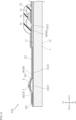
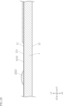
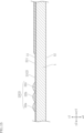
- FIG. 2 is a sectional view taken along line II-II in FIG. 3 is an enlarged plan view showing the thermal print head of FIG. 1.
- FIG. 4 is a sectional view taken along line IV-IV in FIG. 3.
- FIG. 5 is an enlarged view of FIG. 4.
- FIG. 6 is a flowchart showing an example of a method for manufacturing the thermal print head shown in FIG.
- FIG. 7 is a cross-sectional view showing one step of an example of a method for manufacturing the thermal print head shown in FIG.
- FIG. 8 is a cross-sectional view showing one step in an example of a method for manufacturing the thermal print head shown in FIG.
- FIG. 7 is a cross-sectional view showing one step of an example of a method for manufacturing the thermal print head shown in FIG.
- FIG. 8 is a cross-sectional view showing one step in an example of a method for manufacturing the thermal print head shown
- FIG. 9 is a cross-sectional view showing one step of an example of a method for manufacturing the thermal print head shown in FIG.
- FIG. 10 is a cross-sectional view showing one step of an example of a method for manufacturing the thermal print head shown in FIG.
- FIG. 11 is a cross-sectional view showing one step of an example of a method for manufacturing the thermal print head shown in FIG.
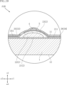
- FIG. 12 is an enlarged cross-sectional view showing a thermal print head according to a second embodiment of the present disclosure.
- FIG. 13 is a flowchart showing an example of a method for manufacturing the thermal print head shown in FIG. 12.
- FIG. 14 is a cross-sectional view showing one step of an example of a method for manufacturing the thermal print head shown in FIG. 12.
- FIG. 15 is a cross-sectional view showing one step of an example of a method for manufacturing the thermal print head shown in FIG. 12.
- FIG. 16 is a cross-sectional view showing one step in an example of a method for manufacturing the thermal print head shown in FIG. 12.
- FIG. 17 is a cross-sectional view showing one step of an example of a method for manufacturing the thermal print head shown in FIG. 12.
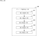
- FIG. 18 is a flowchart showing an example of another method for manufacturing the thermal print head shown in FIG. 12.
- FIG. 19 is an enlarged cross-sectional view showing a thermal print head according to a third embodiment of the present disclosure.
- FIG. 20 is an enlarged cross-sectional view showing a thermal print head according to a fourth embodiment of the present disclosure.
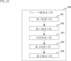
- FIG. 21 is a flowchart showing an example of a method for manufacturing the thermal print head shown in FIG. 20.
- FIG. 22 is a cross-sectional view showing one step of an example of a method for manufacturing the thermal print head shown in FIG. 20.
- FIG. 23 is a cross-sectional view showing one step of an example of a method for manufacturing the thermal print head shown in FIG. 20.
- FIG. 24 is a cross-sectional view showing one step in an example of a method for manufacturing the thermal print head shown in FIG. 20.
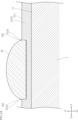
- FIG. 25 is an enlarged sectional view showing a thermal print head according to a first modification of the fourth embodiment.
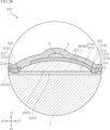
- FIG. 26 is an enlarged sectional view showing a thermal print head according to a second modification of the fourth embodiment.
- a thing A is formed on a thing B and "a thing A is formed on a thing B” mean “a thing A is formed on a thing B” unless otherwise specified.
- "something A is placed on something B” and “something A is placed on something B” mean "something A is placed on something B” unless otherwise specified.
- First embodiment: 1 to 5 show a thermal print head A10 according to a first embodiment of the present disclosure.
- the thermal print head A10 of this embodiment includes a substrate 1, a glaze layer 2, an electrode layer 3, a resistor layer 4, a protective layer 5, a drive IC 71, a sealing resin 72, a wire 73, a connector 74, and a heat dissipation member 75. ing.
- the thermal print head A10 is incorporated into a thermal printer B1 that prints on a print medium 82 that is conveyed while being sandwiched between a platen roller 81 (see FIG. 2).
- the platen roller 81 is arranged to face the heat generating section 41, which will be described later, and presses the print medium 82 against the heat generating section 41 while conveying the print medium 82.
- print media 82 include thermal paper for creating barcode sheets and receipts.
- FIG. 1 is a plan view showing the thermal print head A10.
- FIG. 2 is a sectional view taken along line II-II in FIG.
- FIG. 3 is an enlarged plan view showing the thermal print head A10.
- FIG. 4 is a sectional view taken along line IV-IV in FIG. 3.
- FIG. 5 is an enlarged view of FIG. 4. Note that, for convenience of understanding, the protective layer 5 is omitted in FIGS. 1 and 3. Further, in these figures, the description will be made assuming that the longitudinal direction of the thermal print head A10 is the main scanning direction x, the lateral direction is the sub-scanning direction y, and the thickness direction is the thickness direction z. Regarding the sub-scanning direction y, the lower side of FIGS. 1 and 3 (the left side of FIG.
- FIGS. 1 and 3 are the upstream side y1 where the print medium 82 is sent
- the upper side of FIGS. 1 and 3 (the right side of FIG. 2) ) is the downstream side y2 from which the print medium 82 is discharged.
- the upper side in FIGS. 2 and 4 is defined as a first side z1
- the lower side in FIGS. 2 and 4 is defined as a second side z2.
- the left side in FIGS. 1 and 3 is defined as a first side x1
- the right side in FIGS. 1 and 3 is defined as a second side x2. The same applies to the following figures.
- the substrate 1 is made of ceramic such as AlN, Al 2 O 3 , or zirconia, and has a long rectangular plate shape that extends in the main scanning direction x when viewed in the thickness direction z, as shown in FIG. 1 .
- the thickness of the substrate 1 is not particularly limited, but is, for example, 0.6 mm or more and 1.0 mm or less.
- the substrate 1 has a main surface 11 and a back surface 12, as shown in FIG.
- the main surface 11 and the back surface 12 are surfaces facing opposite to each other in the thickness direction z.
- the main surface 11 faces the first side z1 in the thickness direction z.
- the back surface 12 faces the second side z2 in the thickness direction z.
- a glaze layer 2, an electrode layer 3, a resistor layer 4, and a protective layer 5 are arranged on the main surface 11 .
- a drive IC 71 is mounted on the main surface 11 .
- a heat radiating member 75 made of metal such as Al is arranged on the back surface 12 of the substrate 1.
- a connector 74 is arranged on the board 1. The connector 74 is connected to the connector of the thermal printer B1 when the thermal print head A10 is installed in the thermal printer B1.
- the materials and dimensions of the substrate 1 and the heat radiation member 75 are not limited.
- the thermal print head A10 may include a wiring board on the heat dissipation member 75 separately from the board 1, and the drive IC 71 and the connector 74 may be arranged on the wiring board.
- the glaze layer 2 is arranged on the main surface 11 of the substrate 1, and is made of a glass material such as amorphous glass.
- the glaze layer 2 is formed by disposing a glass paste and then firing it.
- the entire main surface 11 of the substrate 1 is covered with the glaze layer 2.
- the glaze layer 2 may have a configuration in which it does not cover a part of the main surface 11.
- the glaze layer 2 includes a first glaze layer 21, a second glaze layer 22, and a die bonding glaze 24.
- the first glaze layer 21 is arranged in contact with the main surface 11 of the substrate 1, and in this embodiment, it is arranged over the entire main surface 11.
- the first glaze layer 21 has a main surface 211 .
- the main surface 211 is a surface facing the first side z1 in the thickness direction z, and is flat over the entire surface.
- the first glaze layer 21 is provided to eliminate unevenness on the main surface 11 of the substrate 1 and to facilitate lamination of the electrode layer 3.
- the thickness of the first glaze layer 21 (dimension in the thickness direction z) is, for example, about 10 to 20 ⁇ m. Note that the thickness of the first glaze layer 21 is not limited.
- the softening point T1 of the first glaze material, which is the glass material of the first glaze layer 21, is, for example, about 1200 to 1300°C.
- the first glaze layer 21 is formed by disposing a glass paste on the main surface 11 of the substrate 1 by screen printing, for example, and then firing it. Note that the method for forming the first glaze layer 21 is not limited.
- the second glaze layer 22 is placed in contact with the main surface 211 of the first glaze layer 21.
- the second glaze layer 22 extends in the main scanning direction x and is strip-shaped when viewed in the thickness direction z.
- the second glaze layer 22 is disposed on the downstream side y2 of the main surface 211 of the first glaze layer 21 in the sub-scanning direction y.
- the second glaze layer 22 includes a main surface 221 .
- the main surface 221 is a surface facing the first side z1 in the thickness direction z, and is curved over substantially the entire surface.
- the shape of the cross section of the second glaze layer 22 perpendicular to the main scanning direction x is a shape that bulges toward the first side z1 in the thickness direction z.
- the second glaze layer 22 is provided to make it easier to press the heat generating portion 41 of the resistor layer 4 against the print medium 82 or the like. Further, the second glaze layer 22 has a function as a heat storage layer that accumulates the heat generated by the heat generating section 41.
- the thickness of the second glaze layer 22 (dimension in the thickness direction z) is, for example, about 100 to 200 ⁇ m. Note that the thickness of the second glaze layer 22 is not limited.
- the softening point T2 of the second glaze material which is the glass material of the second glaze layer 22, is lower than the softening point T1 of the first glaze material, for example, about 850 to 1000°C. Note that the softening point T2 is not limited.
- the second glaze layer 22 is formed by disposing a glass paste using a dispenser on the main surface 211 of the first glaze layer 21 formed by firing, and then firing it.
- the discharge port of the dispenser is a slit nozzle, and the long side dimension of the slit (dimension in the sub-scanning direction y when arranging the glass paste) depends on the width dimension (dimension in the sub-scanning direction y) of the second glaze layer 22 to be arranged. is set.
- the discharge amount of the dispenser can be adjusted. is set. Further, by adjusting the discharge pressure and moving speed of the dispenser, fine adjustment of the thickness dimension of the second glaze layer 22 is performed.
- the dispenser can adjust the dimensions of the glass paste to be placed by adjusting the dimensions of the slit, the discharge pressure, the moving speed, etc., and it is possible to arrange the glass paste at a thickness dimension that is difficult to arrange with screen printing. is possible.
- the die bonding glaze 24 is disposed in contact with the main surface 211 of the first glaze layer 21, and is spaced apart from the second glaze layer 22 on the upstream side y1 in the sub-scanning direction y. It is a belt-like shape extending in the main scanning direction x, which is provided parallel (or substantially parallel) to the main scanning direction x.
- the die bonding glaze 24 supports a part of the electrode layer 3 and the drive IC 71.
- the thickness of the die bonding glaze 24 (dimension in the thickness direction z) is, for example, about 30 to 50 ⁇ m. Note that the thickness of the die bonding glaze 24 is not limited.
- the softening point of the glass material of the die bonding glaze 24 is lower than the softening point T1 of the glass material of the first glaze layer 21, for example, about 850°C.
- the die bonding glaze 24 is formed by disposing a glass paste, for example, by screen printing, on the main surface 211 of the first glaze layer 21 formed by firing, and then firing this. Note that the method for forming the die bonding glaze 24 is not limited. Further, the glaze layer 2 does not need to include the die bonding glaze 24.
- the electrode layer 3 is for configuring a path for supplying electricity to the resistor layer 4, and is formed of a conductive material.
- the electrode layer 3 is made of resinate Au to which, for example, rhodium, vanadium, bismuth, silicon, or the like is added as an additive element.
- the electrode layer 3 is formed by printing a thick film of resinate Au paste and then firing it.
- the electrode layer 3 may be constructed by laminating a plurality of Au layers.
- the thickness of the electrode layer 3 is, for example, 0.3 ⁇ m or more and 1.5 ⁇ m or less. Note that the material, formation method, and thickness of the electrode layer 3 are not limited.
- the electrode layer 3 is arranged on the glaze layer 2. As shown in FIG.
- the electrode layer 3 includes a common electrode 33 and a plurality of individual electrodes 36. Note that, for convenience of understanding, the common electrode 33 and the individual electrodes 36 are hatched in FIG. Similarly, an Ag layer 351 to be described later is also hatched, and the resistor layer 4 is dotted.
- the common electrode 33 has a plurality of common electrode strip portions 34 and connecting portions 35.
- the connecting portion 35 is disposed near the downstream end y2 of the substrate 1 in the sub-scanning direction y, and has a band shape extending in the main-scanning direction x.
- the plurality of common electrode strips 34 each extend from the connecting portion 35 in the sub-scanning direction y, and are arranged at equal pitches and spaced apart from each other in the main-scanning direction x.
- an Ag layer 351 is laminated on the connecting portion 35.
- the Ag layer 351 is for reducing the resistance value of the connecting portion 35.
- the thickness of the Ag layer 351 is, for example, 2 ⁇ m or more and 10 ⁇ m or less.
- the plurality of individual electrodes 36 are for partially supplying current to the resistor layer 4, and are portions having opposite polarity to the common electrode 33.
- the individual electrodes 36 extend from the resistor layer 4 toward the drive IC 71 .
- the plurality of individual electrodes 36 are arranged in the main scanning direction x, and each has an individual electrode strip portion 38, a connecting portion 37, and a bonding portion 39.
- Each individual electrode strip 38 is a strip extending in the sub-scanning direction y, and is arranged between any two adjacent common electrode strips 34 of the common electrode 33.
- the distance between the individual electrode strip portions 38 of the adjacent individual electrodes 36 and the common electrode strip portion 34 of the common electrode 33 is, for example, 40 ⁇ m or less.
- the center-to-center distance between the individual electrode strip portions 38 of adjacent individual electrodes 36 and the common electrode strip portion 34 of the common electrode 33 is, for example, 20 ⁇ m or more and 100 ⁇ m or less.
- the connecting portion 37 is a portion extending from the individual electrode strip portion 38 toward the drive IC 71.
- the connecting portion 37 has a parallel portion 371 and an oblique portion 372.
- One end of the parallel portion 371 is connected to the bonding portion 39 and extends along the sub-scanning direction y.
- the oblique portion 372 is inclined with respect to the sub-scanning direction y.
- the oblique portion 372 is sandwiched between the parallel portion 371 and the individual electrode strip portion 38 in the sub-scanning direction y. Further, the plurality of individual electrodes 36 are integrated into the drive IC 71.
- the bonding part 39 is arranged at the upstream y1 end of the individual electrode 36 in the sub-scanning direction y, and is connected to the parallel part 371.
- a wire 73 for electrically connecting the individual electrode 36 and the drive IC 71 is bonded to the bonding portion 39 .
- the plurality of bonding parts 39 include a first bonding part 39A and a second bonding part 39B.
- the width (dimension in the main scanning direction x) of the parallel portion 371 sandwiched between two adjacent first bonding portions 39A is, for example, 20 ⁇ m or more and 30 ⁇ m or less.
- the second bonding portion 39B is located on the side farther away from the resistor layer 4 (upstream side y1) than the first bonding portion 39A in the sub-scanning direction y.
- the second bonding portion 39B is connected to a parallel portion 371 sandwiched between two adjacent first bonding portions 39A.
- each part of the electrode layer 3 are not particularly limited, and can have various configurations. Moreover, the material of each part of the electrode layer 3 is not limited either.
- the resistor layer 4 is made of, for example, ruthenium oxide, which has a higher resistivity than the material forming the electrode layer 3.
- the resistor layer 4 is disposed on the second glaze layer 22 and is formed in a band shape extending in the main scanning direction x.
- the resistor layer 4 is formed by printing a thick film of paste such as ruthenium oxide and then firing the paste.
- the resistor layer 4 intersects with and is in contact with the plurality of common electrode strips 34 of the common electrode 33 and the individual electrode strips 38 of the plurality of individual electrodes 36 .
- the resistor layer 4 is arranged on the opposite side of the substrate 1 (the first side z1 in the thickness direction z) with respect to the plurality of common electrode strips 34 of the common electrode 33 and the individual electrode strips 38 of the plurality of individual electrodes 36. ) are laminated. A portion of the resistor layer 4 sandwiched between each common electrode strip portion 34 and each individual electrode strip portion 38 serves as a heat generating portion 41 that generates heat when partially energized by the electrode layer 3 .
- the plurality of heat generating parts 41 are arranged in the second glaze layer 22 and arranged along the main scanning direction x. As shown in FIG. 2, in the thermal printer B1, the plurality of heat generating parts 41 are opposed to the platen roller 81.
- Print dots are formed by the heat generated by the heat generating section 41.
- the thickness of the resistor layer 4 is, for example, 1 ⁇ m or more and 10 ⁇ m or less, preferably 3 ⁇ m or more and 10 ⁇ m or less. Note that the material and thickness of the resistor layer 4 are not limited.
- the protective layer 5 is for protecting the electrode layer 3 and the resistor layer 4, and covers almost the entirety of the electrode layer 3 and the resistor layer 4. However, the protective layer 5 exposes a region including the bonding portions 39 of the plurality of individual electrodes 36.
- the protective layer 5 is made of a glass material such as amorphous glass.
- the protective layer 5 is formed by printing a thick film of glass paste and then firing it.
- the thickness of the protective layer 5 is, for example, 0.5 ⁇ m or more and 10 ⁇ m or less. Note that the material, formation method, and thickness of the protective layer 5 are not limited.
- the thermal print head A10 may further include a second protective layer that covers a portion of the protective layer 5.
- the drive IC 71 functions to partially generate heat in the resistor layer 4 by selectively energizing the plurality of individual electrodes 36.
- a plurality of drive ICs 71 are arranged on the die bonding glaze 24.
- the drive IC 71 is provided with a plurality of pads.
- the pads of the drive IC 71 and the plurality of individual electrodes 36 are connected via a plurality of wires 73 bonded to each pad.
- the wire 73 is made of Au, for example.
- the drive IC 71 and the wires 73 are covered with a sealing resin 72.
- the sealing resin 72 is made of, for example, a black insulating soft resin.
- the drive IC 71 and the connector 74 are connected via the wire 73 and the wiring on the board 1.
- FIG. 6 is a flowchart illustrating an example of a method for manufacturing the thermal print head A10.
- 7 to 11 are each a cross-sectional view showing one step of an example of a method for manufacturing the thermal print head A10, and correspond to the cross section shown in FIG. 4.
- the main scanning direction x, sub-scanning direction y, and thickness direction z shown in FIGS. 6 to 11 indicate the same directions as in FIGS. 1 to 5.
- the manufacturing method of the thermal print head A10 includes a substrate preparation step S10, a glaze layer forming step S20, an electrode layer forming step S30, a resistor layer forming step S40, a protective layer forming step S50, and a drive IC mounting and sealing step. It includes a stopping step S60 and an attaching step S70.
- a substrate 1 made of, for example, AlN, Al 2 O 3 or zirconia is prepared (substrate preparation step S10).
- the substrate 1 has a main surface 11 and a back surface 12 facing oppositely to each other in the thickness direction z.
- the main surface 11 faces the first side z1 in the thickness direction z.
- the back surface 12 faces the second side z2 in the thickness direction z.
- the glaze layer 2 is formed on the substrate 1, as shown in FIGS. 7 to 10 (glaze layer forming step S20).
- a glass paste of the first glaze material is placed on the entire main surface 11 of the substrate 1 by screen printing (first placement step S21).
- first glaze layer 21 is formed on the main surface 11, as shown in FIG. 7 (first firing step S22).
- the main surface 211 of the first glaze layer 21 is flat over the entire surface.
- a glass paste is placed at a predetermined position on the main surface 211 of the first glaze layer 21 by screen printing and fired, thereby forming a die bonding glaze 24 on the main surface 211, as shown in FIG. Ru.
- a glass paste 22A of the second glaze material is arranged in a belt shape extending in the main scanning direction x at a predetermined position on the main surface 211 of the first glaze layer 21 using a dispenser (second arrangement).
- a dispenser second arrangement
- the glass paste 22A is disposed with a larger thickness than when disposed by screen printing.
- the second glaze material is placed on the main surface 211 of the first glaze layer 21. Due to the coffee ring effect during drying, the second glaze material has a concave portion extending in the main scanning direction x in the central portion when viewed in the thickness direction z.
- the second glaze layer 22 is formed on the main surface 211 of the first glaze layer 21, as shown in FIG. 10 (second firing step S24).
- the second glaze layer 22 has a curved shape in which the main surface 221 protrudes toward the first side z1 in the thickness direction z due to the surface tension of the softened second glaze material. Therefore, as shown in FIG. 10, the cross section of the second glaze layer 22 perpendicular to the main scanning direction x has a shape that bulges toward the first side z1 in the thickness direction z.
- the firing temperature in the second firing step S24 to a temperature between the softening points T1 and T2 only the second glaze material can be fired without softening the first glaze layer 21.
- the glaze layer 2 is formed on the substrate 1.
- a metal film is formed by printing a thick film of resinate Au paste and then firing it.
- the metal film is patterned using, for example, etching.
- the electrode layer 3 is formed on the glaze layer 2 (electrode layer forming step S30).
- a thick film of paste containing Ag is printed on a predetermined area on the connecting portion 35 of the electrode layer 3, and then this is fired.
- an Ag layer 351 is formed as shown in FIG. 11.
- a resistor paste containing a resistor such as ruthenium oxide is printed as a thick film, and this is fired.
- the resistor layer 4 is formed (resistor layer forming step S40).
- the protective layer 5 is formed by, for example, printing a thick film of glass paste and baking it (protective layer forming step S50).
- the drive IC 71 is mounted, the wires 73 are bonded, and the sealing resin 72 is formed (drive IC mounting and sealing step S60).
- the connector 74 is attached to the substrate 1, the substrate 1 is attached to the heat dissipation member 75, etc. (attachment step S70).
- the thermal print head A10 shown in FIGS. 1 to 5 is manufactured.
- the manufacturing method described above is an example and is not limited thereto.
- the glaze layer 2 of the thermal print head A10 includes a second glaze layer 22.
- the second glaze layer 22 is formed by disposing a glass paste 22A using a dispenser on the main surface 211 of the first glaze layer 21 disposed on the main surface 11 of the substrate 1, and then firing it. Therefore, the thickness of the second glaze layer 22 can be increased compared to a case where a glass paste placed by screen printing is fired. Therefore, in the thermal print head A10, the heat generating section 41 can be easily pressed against the print medium 82, etc., and the heat generated by the heat generating section 41 can be efficiently transmitted to the print medium 82. Further, since the second glaze layer 22 can accumulate more heat generated by the heat generating section 41, the thermal print head A10 can suppress the amount of heat that must be generated by the heat generating section 41. Therefore, the thermal print head A10 can suppress power consumption and further improve printing efficiency.
- the second glaze layer 22 is formed on the main surface 211 of the first glaze layer 21 formed by firing in the first firing step S22. Therefore, in the thermal print head A10, the second glaze layer 22 is first formed on the substrate 1, and then the first glaze layer 21 is formed adjacent to the second glaze layer 22. can be arranged at a position away from the main surface 11 of the substrate 1 in the thickness direction z. This makes it easier for the thermal print head A10 to press the heat generating section 41 against the print medium 82 or the like.
- the softening point T2 of the second glaze material is lower than the softening point T1 of the first glaze material. Therefore, in the second firing step S24, by setting the firing temperature to a temperature between the softening points T1 and T2, only the second glaze material can be fired without softening the first glaze layer 21.
- FIG. 12 to 17 are diagrams for explaining a thermal print head A20 according to a second embodiment of the present disclosure.
- FIG. 12 is an enlarged sectional view showing the thermal print head A20, and corresponds to FIG. 5.
- FIG. 13 is a flowchart illustrating an example of a method for manufacturing the thermal print head A20, and corresponds to FIG. 6.
- 14 to 17 are cross-sectional views showing one step of an example of a method for manufacturing the thermal print head A20, and correspond to FIGS. 9 and 10.
- the thermal print head A20 of this embodiment differs from the embodiments described above in that the glaze layer 2 further includes a third glaze layer 23.
- the configuration and operation of other parts of this embodiment are similar to those of the first embodiment.
- each part of the said 1st Embodiment may be combined arbitrarily.
- the second glaze layer 22 includes regions 22a, 22b, and 22c, as shown in FIG. 12.
- the regions 22a, 22b, and 22c each have the same shape as the second glaze layer 22 according to the first embodiment, and extend in the main scanning direction x.
- the regions 22a, 22b, and 22c are spaced apart from each other in the sub-scanning direction y.
- the glaze layer 2 further includes a third glaze layer 23.
- the third glaze layer 23 is interposed between the second glaze layer 22 and the plurality of heat generating parts 41, and covers the entire second glaze layer 22 (regions 22a, 22b, 22c). Note that the third glaze layer 23 does not need to cover a part of the second glaze layer 22.
- the third glaze layer 23 extends in the main scanning direction x and is strip-shaped when viewed in the thickness direction z.
- the softening point T3 of the third glaze material which is the glass material of the third glaze layer 23, is lower than the softening point T2 of the second glaze material, for example, about 850°C.
- the glaze layer forming step S20 further includes a third arrangement step S25 and a third firing step S26.
- the steps (S10, S30 to S70) other than the glaze layer forming step S20 are the same as in the first embodiment.
- the first arrangement step S21, the first firing step S22, and the step of forming the die bonding glaze 24 are the same as in the first embodiment (see FIGS. 7 and 8).
- the second arrangement step S23 by repeating the arrangement of the glass paste 22A by the dispenser three times, as shown in FIG. 14, three strip-shaped glass pastes 22A extending in the main scanning direction x are arranged at a distance from each other.
- the second glaze layer 22 (regions 22a, 22b, 22c) is formed on the main surface 211 of the first glaze layer 21, as shown in FIG. is formed (second firing step S24).
- glass paste 23A of the third glaze material is placed by a dispenser to cover the entire second glaze layer 22 (regions 22a, 22b, 22c) (third placement step S25).
- the glass paste 23A is arranged in a band shape extending in the main scanning direction x.
- the surface of the glass paste 23A has irregularities formed in accordance with the shapes of the regions 22a, 22b, and 22c.
- the third glaze material is placed to cover the second glaze layer 22 (regions 22a, 22b, 22c).
- the third glaze layer 23 covering the second glaze layer 22 is formed as shown in FIG. 17 (third firing step S26).
- the third glaze layer 23 has a curved shape in which the main surface 231 protrudes toward the first side z1 in the thickness direction z due to the surface tension of the softened third glaze material. Furthermore, by setting the firing temperature in the third firing step S26 to a temperature between the softening points T2 and T3, only the third glaze material can be fired without softening the second glaze layer 22.
- the thermal print head A20 has the same effects as the thermal print head A10.
- the glaze layer 2 of the thermal print head A20 includes a second glaze layer 22 (regions 22a, 22b, 22c) and a third glaze layer 23.
- the combination of the second glaze layer 22 (regions 22a, 22b, 22c) and the third glaze layer 23 may be referred to as a "partial glaze”.
- the partial glaze is obtained by further covering the second glaze layer 22 (regions 22a, 22b, 22c) with a third glaze layer 23, and has a larger thickness than the second glaze layer 22. Therefore, compared to the thermal print head A10, the thermal print head A20 can further suppress power consumption and further improve printing efficiency.
- the second glaze layer 22 includes regions 22a, 22b, and 22c spaced apart in the sub-scanning direction y. Therefore, the partial glaze can have a larger dimension in the sub-scanning direction y than the second glaze layer 22 according to the first embodiment. As a result, the volume of the partial glaze can be increased, so that more heat generated by the heat generating portion 41 can be accumulated. Therefore, the thermal print head A20 can further improve printing efficiency.
- the third glaze layer 23 is formed to cover the second glaze layer 22 formed by firing in the second firing step S24. Therefore, compared to the thermal print head A10, the thermal print head A20 can dispose the heat generating part 41 at a position farther away from the main surface 11 of the substrate 1 in the thickness direction z. This makes it easier for the thermal print head A20 to press the heat generating portion 41 against the print medium 82 or the like.
- the softening point T3 of the third glaze material is lower than the softening point T2 of the second glaze material. Therefore, in the third firing step S26, by setting the firing temperature to a temperature between the softening points T2 and T3, only the third glaze material can be fired without softening the second glaze layer 22.
- the second glaze layer 22 includes three regions 22a, 22b, and 22c, but the present invention is not limited to this.
- the second glaze layer 22 may include two regions, or may include four or more regions. The larger the number of regions included in the second glaze layer 22, the larger the dimension of the partial glaze in the sub-scanning direction y.
- the second glaze layer 22 (regions 22a, 22b, 22c) is formed in the second firing step S24, and then the third glaze material is placed in the third placement step S25, but this is not limited to this. I can't do it.
- the third glaze material is first arranged in the third arrangement step S25, and the second glaze material and the third glaze material are combined in the second firing step S24. It may also be fired.
- the softening point T3 of the third glaze material may be the same (or substantially the same) as the softening point T2 of the second glaze material.
- FIG. 19 is a diagram for explaining a thermal print head A30 according to a third embodiment of the present disclosure.
- FIG. 19 is an enlarged cross-sectional view showing the thermal print head A30, and corresponds to FIG. 5.
- the thermal print head A30 of this embodiment differs from the above-described second embodiment in that the second glaze layer 22 consists of one region.
- the configuration and operation of other parts of this embodiment are similar to those of the second embodiment. Note that each part of the first and second embodiments described above may be combined arbitrarily.
- the second glaze layer 22 according to the present embodiment does not include a plurality of regions, and has the same configuration as the second glaze layer 22 according to the first embodiment.
- the glaze layer 2 includes the third glaze layer 23, similar to the second embodiment.
- the third glaze layer 23 has the same configuration as the third glaze layer 23 according to the second embodiment.
- the method for manufacturing the thermal print head A30 is the same as the method for manufacturing the thermal print head A20, except that the glass paste 22A is placed only once in the second placement step S23.
- the thermal print head A30 has the same effects as the thermal print head A10.
- the glaze layer 2 of the thermal print head A30 includes a partial glaze (a combination of the second glaze layer 22 and the third glaze layer 23).
- the partial glaze is obtained by further covering the second glaze layer 22 with a third glaze layer 23, and has a larger thickness than the second glaze layer 22. Therefore, compared to the thermal print head A10, the thermal print head A30 can further suppress power consumption and further improve printing efficiency.
- the third glaze layer 23 is formed to cover the second glaze layer 22 formed by firing in the second firing step S24. Therefore, compared to the thermal print head A10, the thermal print head A30 can dispose the heat generating part 41 at a position farther away from the main surface 11 of the substrate 1 in the thickness direction z. This makes it easier for the thermal print head A30 to press the heat generating section 41 against the print medium 82 or the like.
- the softening point T3 of the third glaze material is lower than the softening point T2 of the second glaze material. Therefore, in the third firing step S26, by setting the firing temperature to a temperature between the softening points T2 and T3, only the third glaze material can be fired without softening the second glaze layer 22.
- FIG. 20 to 24 are diagrams for explaining a thermal print head A40 according to a fourth embodiment of the present disclosure.
- FIG. 20 is an enlarged sectional view showing the thermal print head A40, and is a further enlarged view of the diagram corresponding to FIG.
- FIG. 21 is a flowchart illustrating an example of a method for manufacturing the thermal print head A40, and corresponds to FIG. 6. In addition, in FIG. 21, only the glaze layer forming step S20 is described, and the description of other steps is omitted.
- 22 to 24 are cross-sectional views showing one step of an example of a method for manufacturing the thermal print head A40.
- the thermal print head A40 of this embodiment differs from the first embodiment described above in that a recess is formed in the first glaze layer 21 and the second glaze layer 22 is disposed in the recess.
- the configuration and operation of other parts of this embodiment are similar to those of the first embodiment. Note that each part of the first to third embodiments described above may be combined arbitrarily.
- the first glaze layer 21 includes a recess 212.
- the recess 212 is a groove recessed from the main surface 211 toward the second side z2 in the thickness direction z, and extends linearly in the main scanning direction x.
- the recess 212 has an elongated rectangular shape that extends in the main scanning direction x when viewed in the thickness direction z.
- the depth dimension (dimension in the thickness direction z) of the recess 212 is not limited.
- the recess 212 is formed, for example, by wet blasting. Wet blasting is a processing technology that processes a target object by accelerating a slurry made by mixing abrasive material and water (sometimes containing chemicals) with compressed air and spraying it toward the target object. .
- the recesses 212 are formed by forming a mask layer on the main surface 211 and performing processing by wet blasting on the region on the main surface 211 where the mask layer is not formed.
- the method for forming the recess 212 is not limited.
- the recess 212 may be formed, for example, by shot blasting other than wet blasting, by etching, or by cutting with a dicing blade, laser, or the like.
- the recess 212 includes two recess edges 212a. Each recess edge 212a is a boundary between the recess 212 and the main surface 211, and extends in the main scanning direction x.
- the inclination angle ⁇ of the side surface 212b of the recess 212 with respect to the main surface 211 is approximately a right angle. Note that the inclination angle ⁇ is not limited to a substantially right angle.
- the second glaze layer 22 is arranged inside the recess 212 when viewed in the thickness direction z.
- the second glaze layer 22 is formed by placing glass paste in the recess 212 and firing it. Although the glass paste is fluid, when placed in the recess 212, surface tension prevents it from exceeding the recess edge 212a. Also, during firing, the glass paste is fluidized by heating, but surface tension prevents it from exceeding the edge 212a of the recess.
- the recess 212 only needs to have a recess edge 212a for preventing the glass paste from flowing and spreading onto the main surface 211. Therefore, the depth dimension of the recess 212 may be relatively small. Further, it is desirable that the inclination angle ⁇ is relatively large.
- the glaze edge 222 which is the edge of the second glaze layer 22 in the sub-scanning direction y, coincides with the recess edge 212a of the recess 212. More specifically, the glaze edge 222 on the upstream side y1 in the sub-scanning direction y and the recess edge 212a on the upstream side y1 in the sub-scanning direction y coincide with the glaze edge 222 on the downstream side y2 in the sub-scanning direction y.
- the concave portion edge 212a on the downstream side y2 in the sub-scanning direction y coincides with the concave portion edge 212a.
- the second glaze layer 22 is formed with a formation region defined by the recess 212 .
- the method for manufacturing the thermal print head A40 includes a recess forming step S27 added between the first firing step S22 and the second arrangement step S23.
- the steps (S10, S30 to S70) other than the glaze layer forming step S20 are the same as in the first embodiment.
- the first arrangement step S21, the first firing step S22, and the step of forming the die bonding glaze 24 are the same as in the first embodiment (see FIGS. 7 and 8).
- recesses 212 are formed in the first glaze layer 21 (recess formation step S27).
- a predetermined mask layer 99 (indicated by a two-dot chain line in FIG. 22) is formed on a part of the main surface 211 of the first glaze layer 21.
- the mask layer 99 is formed, for example, by patterning a resist using a photolithography technique.
- the mask layer 99 has an opening 99a that penetrates the mask layer 99 in the thickness direction z and extends in the main scanning direction x.
- wet blasting is performed to form a recess 212 that is recessed from the main surface 211 in the thickness direction z and extends in the main scanning direction x, as shown in FIG.
- the shape of the recess 212 when viewed in the thickness direction z corresponds to the opening 99a of the mask layer 99.
- the recess 212 includes a bottom surface 212c facing the first side z1 in the thickness direction z.
- the bottom surface 212c has irregularities formed by wet blasting. Thereafter, mask layer 99 is removed.
- a glass paste 22A of the second glaze material is placed in the recess 212 of the first glaze layer 21 using a dispenser.
- the placed glass paste 22A has fluidity, surface tension prevents it from exceeding the recess edge 212a.
- the method for disposing the glass paste 22A is not limited, and may be disposed by, for example, screen printing.
- the second glaze layer 22 is formed in the recess 212 of the first glaze layer 21, as shown in FIG.
- the glass paste 22A is fluidized by heating during firing, surface tension prevents it from exceeding the recess edge 212a.
- the second glaze layer 22 is formed in a state where the glaze edge 222 and the recess edge 212a are aligned with each other when viewed in the thickness direction z.
- the thermal print head A40 has the same effects as the thermal print head A10.
- the first glaze layer 21 includes a recess 212 that is recessed from the main surface 211 toward the second side z2 in the thickness direction z and extends in the main scanning direction x.
- the second glaze layer 22 is disposed inside the recess 212 when viewed in the thickness direction z.
- the second glaze layer 22 is formed by preventing the fluid glass paste 22A from exceeding the recess edge 212a of the recess 212 during the manufacturing process. Thereby, the second glaze layer 22 is formed in the formation region defined by the recess 212 without spreading on the main surface 211. Therefore, the thermal print head A40 can make each glaze edge 222 of the second glaze layer 22 linear. Furthermore, the thermal print head A40 can prevent the second glaze layer 22 from spreading on the main surface 211 and reducing the thickness dimension.
- the recess 212 is formed by wet blasting. Therefore, the recess 212 can be easily formed in a short time. Further, the recess 212 can be formed so that the inclination angle ⁇ is approximately a right angle.
- FIGS. 25 and 26 show a modification of the thermal print head A40 according to the fourth embodiment.
- the same or similar elements as in the above embodiment are given the same reference numerals as in the above embodiment, and redundant explanation will be omitted.
- FIG. 25 is a diagram for explaining a thermal print head A41 according to a first modification of the fourth embodiment.
- FIG. 25 is an enlarged sectional view showing the thermal print head A41, and corresponds to FIG. 20.
- the recess 212 according to this modification is composed of two grooves 213 lined up in the sub-scanning direction y.
- Each groove 213 is a groove recessed from the main surface 211 toward the second side z2 in the thickness direction z, and extends in the main scanning direction x.
- Each groove 213 has an elongated rectangular shape that extends in the main scanning direction x when viewed in the thickness direction z.
- Each groove 213 is formed, for example, by wet blasting. Note that the method of forming each groove 213 is not limited.
- Each groove 213 includes a recess edge 213a and a recess edge 213b.
- the recess edge 213a and the recess edge 213b are boundaries between each groove 213 and the main surface 211, and extend in the main scanning direction x.
- the recess edge 213a is an edge located on the opposite side of the other groove 213 in the sub-scanning direction y.
- the recess edge 213b is an edge located on the other groove 213 side in the sub-scanning direction y.
- the main surface 211 is divided into three parts by a recess 212 (two grooves 213). All three portions have an elongated rectangular shape that extends in the main scanning direction x.
- the main surface 211 includes a groove portion 211a.
- the inter-groove portion 211a is a portion between two grooves 213 among the three portions. In other words, the groove portion 211a is connected to the groove 213 via the recess edge 213b.
- the second glaze layer 22 is disposed on the groove portion 211a of the main surface 211 and in each groove 213 when viewed in the thickness direction z.
- the glass paste 22A which is the material of the second glaze layer 22, has fluidity, but when placed on the first glaze layer 21, surface tension prevents it from exceeding the recess edge 213a. Also, during firing, the glass paste 22A is fluidized by heating, but surface tension prevents it from exceeding the edge 213a of the recess. When viewed in the thickness direction z, the glaze edge 222 and the recess edge 213a match.
- the glaze edge 222 on the upstream side y1 in the sub-scanning direction y and the recess edge 213a of the groove 213 on the upstream side y1 in the sub-scanning direction y match, and the glaze edge 222 on the upstream side y1 in the sub-scanning direction y coincides with the glaze edge 213a on the downstream side y2 in the sub-scanning direction y.
- the edge 222 and the recess edge 213a of the groove 213 on the downstream side y2 in the sub-scanning direction y are aligned.
- the second glaze layer 22 is formed with a formation region defined by the recess edge 213 a of each groove 213 of the recess 212 .
- the first glaze layer 21 includes a recess 212 that is recessed from the main surface 211 toward the second side z2 in the thickness direction z and that is made up of two grooves 213 that extend in the main scanning direction x. ing. Further, the second glaze layer 22 is disposed on the groove portion 211a of the main surface 211 and in each groove 213 when viewed in the thickness direction z. The second glaze layer 22 is formed by preventing the fluid glass paste 22A from exceeding the recessed edge 213a of each groove 213 during the manufacturing process. Thereby, the second glaze layer 22 is formed in the formation region defined by the recess 212 without spreading on the main surface 211.
- each glaze edge 222 of the second glaze layer 22 can be made straight, and the thickness can be increased by spreading the second glaze layer 22 on the main surface 211. It is possible to suppress the size from becoming smaller.
- FIG. 26 is a diagram for explaining a thermal print head A42 according to a second modification of the fourth embodiment.
- FIG. 26 is an enlarged sectional view showing the thermal print head A42, and corresponds to FIG. 20.
- the formation region of the second glaze layer 22 is different from the first modification described above.
- the recess 212 consists of two grooves 213 aligned in the sub-scanning direction y.
- Each groove 213 includes a recess edge 213a and a recess edge 213b.
- the main surface 211 includes an inter-groove portion 211 a located between the two grooves 213 .
- the second glaze layer 22 is disposed on the groove portion 211a of the main surface 211 and is not disposed on the two grooves 213 when viewed in the thickness direction z. That is, the two grooves 213 are exposed from the second glaze layer 22.
- the glass paste 22A which is the material of the second glaze layer 22, has fluidity, but when placed on the first glaze layer 21, surface tension prevents it from exceeding the edge 213b of the recess. Also, during firing, the glass paste 22A is fluidized by heating, but surface tension prevents it from exceeding the edge 213b of the recess. When viewed in the thickness direction z, the glaze edge 222 and the recess edge 213b match.
- the glaze edge 222 on the upstream side y1 in the sub-scanning direction y and the recess edge 213b of the groove 213 on the upstream side y1 in the sub-scanning direction y match, and the glaze edge 222 on the upstream side y1 in the sub-scanning direction y coincides with the glaze edge 213b on the downstream side y2 in the sub-scanning direction y.
- the edge 222 and the recess edge 213b of the groove 213 on the downstream side y2 in the sub-scanning direction y are aligned.
- the second glaze layer 22 is formed with a formation region defined by the recess edge 213b of each groove 213 of the recess 212.
- the first glaze layer 21 includes a recess 212 consisting of two grooves 213.
- the second glaze layer 22 is disposed only on the groove portion 211a of the main surface 211 when viewed in the thickness direction z.
- the second glaze layer 22 is formed by preventing the fluid glass paste 22A from exceeding the recessed edge 213b of each groove 213 during the manufacturing process. Thereby, the second glaze layer 22 is formed in the formation region defined by the recess 212 without spreading on the main surface 211. Therefore, in the thermal print head A42, like the thermal print head A40, each glaze edge 222 of the second glaze layer 22 can be made straight, and the thickness can be increased by spreading the second glaze layer 22 on the main surface 211. It is possible to suppress the size from becoming smaller.
- thermal print head and its manufacturing method according to the present disclosure, and the thermal printer equipped with the thermal print head are not limited to the embodiments described above.
- the specific configuration of each part of the thermal print head and thermal printer according to the present disclosure, and the specific processing of each step of the method for manufacturing a thermal print head according to the present disclosure can be variously changed in design.
- the present disclosure includes the embodiments described in the appendix below.
- a substrate (1) having a substrate main surface (11) facing a first side (z1) in the thickness direction (z); a first glaze layer (21) disposed on the substrate main surface and having a first glaze main surface (211) facing the first side; a band-shaped second glaze layer (22) disposed in contact with the first glaze main surface and extending in the main scanning direction (x); a resistor layer (4) including a plurality of heat generating parts (41) arranged along the main scanning direction; Equipped with The plurality of heat generating parts are arranged in the second glaze layer, Thermal print head (A10).
- Appendix 2. the first glaze layer is disposed over the entire main surface of the substrate; The thermal print head described in Appendix 1.
- the second glaze layer includes a second glaze main surface (221) facing the first side, The first glazed main surface is flat compared to the second glazed main surface.
- the thermal print head according to appendix 1 or 2.
- Appendix 4 The second softening point (T2) of the second glaze layer is lower than the first softening point (T1) of the first glaze layer.
- the thermal print head according to any one of Supplementary Notes 1 to 3.
- Supplementary note 5 second and third embodiments, FIG. 12, FIG. 19. further comprising a belt-shaped third glaze layer (23) interposed between the second glaze layer and the plurality of heat generating parts and extending in the main scanning direction;
- the thermal print head according to any one of Supplementary Notes 1 to 4.
- the second glaze layer includes a plurality of regions (22a, 22b, 22c) spaced apart from each other in the sub-scanning direction.
- Appendix 7. The third softening point (T3) of the third glaze layer is lower than the second softening point of the second glaze layer.
- the thermal print head according to appendix 5 or 6. Appendix 7-1.
- the third softening point of the third glaze layer is the same (or approximately the same) as the second softening point of the second glaze layer.
- the substrate includes ceramics.
- the first glaze layer further includes a recess (212) recessed from the first glaze main surface in the thickness direction,
- the recess includes a recess edge (212a) that is a boundary with the first glaze main surface and extends in the main scanning direction, When viewed in the thickness direction, a glaze edge (222) of the second glaze layer and an edge of the recess are aligned;
- the thermal print head according to any one of appendices 1 to 8.
- the recess is a single groove extending in the main scanning direction, the second glaze layer is disposed inside the recess when viewed in the thickness direction;
- the recess includes two grooves (213) arranged in the sub-scanning direction,
- the second glaze layer is disposed in an inter-groove portion (211a) that is a region between the two grooves on the first glaze main surface and in the two grooves when viewed in the thickness direction.
- the recess includes two grooves aligned in the sub-scanning direction,
- the second glaze layer is disposed in an inter-groove portion that is a region between the two grooves on the first glaze main surface when viewed in the thickness direction, the two grooves are exposed from the second glaze layer,
- the recess includes a bottom surface (212c) facing the first side in the thickness direction, unevenness is formed on the bottom surface;
- the thermal print head according to any one of appendices 9 to 12.
- Appendix 14, Figure 2 The thermal print head according to any one of appendices 1 to 13, a platen roller (81) arranged to face the plurality of heat generating parts; It is equipped with Thermal printer (B1).
- the second glaze material arranged in the second arrangement step includes a plurality of regions (22A) spaced apart from each other in the sub-scanning direction (y), After the second arranging step, the method further includes a third arranging step (S25) of arranging a third glaze material (23A) in the form of a belt extending in the main scanning direction so as to cover the second glaze material.
- the third arrangement step is performed after the second firing step, After the third arrangement step, the method further includes a third firing step (S26) of firing the third glaze material.
- the second firing step is performed after the third arranging step, and the second glaze material and the third glaze material are fired.
- a first glaze formed by firing the first glaze material is recessed from the main surface in the thickness direction and extends in the main scanning direction. further comprising a recess forming step (S27) for forming a recess;
- S27 recess forming step for forming a recess
- the second glaze material is placed in the recess,
- the recess includes two grooves aligned in the sub-scanning direction,
- the second glaze is applied to an inter-groove portion, which is a region between the two grooves on the first glaze main surface, and to the two grooves, when viewed in the thickness direction. placing materials,
- the recess includes two grooves aligned in the sub-scanning direction, In the second arranging step, the second glaze material is arranged only in an inter-groove portion that is a region between the two grooves on the first glaze main surface when viewed in the thickness direction.
- the recess is formed by wet blasting.
- Appendix 25. the first glaze material is disposed over the entire main surface of the substrate;
Landscapes
- Electronic Switches (AREA)
Priority Applications (1)
| Application Number | Priority Date | Filing Date | Title |
|---|---|---|---|
| JP2024519194A JPWO2023214514A1 (https=) | 2022-05-02 | 2023-04-21 |
Applications Claiming Priority (4)
| Application Number | Priority Date | Filing Date | Title |
|---|---|---|---|
| JP2022-075801 | 2022-05-02 | ||
| JP2022075801 | 2022-05-02 | ||
| JP2022167482 | 2022-10-19 | ||
| JP2022-167482 | 2022-10-19 |
Publications (1)
| Publication Number | Publication Date |
|---|---|
| WO2023214514A1 true WO2023214514A1 (ja) | 2023-11-09 |
Family
ID=88646425
Family Applications (1)
| Application Number | Title | Priority Date | Filing Date |
|---|---|---|---|
| PCT/JP2023/015860 Ceased WO2023214514A1 (ja) | 2022-05-02 | 2023-04-21 | サーマルプリントヘッド、サーマルプリントヘッドの製造方法、およびサーマルプリンタ |
Country Status (2)
| Country | Link |
|---|---|
| JP (1) | JPWO2023214514A1 (https=) |
| WO (1) | WO2023214514A1 (https=) |
Citations (4)
| Publication number | Priority date | Publication date | Assignee | Title |
|---|---|---|---|---|
| JPS63256462A (ja) * | 1987-04-14 | 1988-10-24 | Rohm Co Ltd | サ−マルヘツド |
| JP2006205369A (ja) * | 2005-01-25 | 2006-08-10 | Kyocera Corp | グレーズド基板 |
| CN102303458A (zh) * | 2011-07-29 | 2012-01-04 | 山东华菱电子有限公司 | 热敏打印头及其制造方法 |
| WO2021200401A1 (ja) * | 2020-04-01 | 2021-10-07 | ローム株式会社 | サーマルプリントヘッド、およびサーマルプリントヘッドの製造方法 |
-
2023
- 2023-04-21 WO PCT/JP2023/015860 patent/WO2023214514A1/ja not_active Ceased
- 2023-04-21 JP JP2024519194A patent/JPWO2023214514A1/ja active Pending
Patent Citations (4)
| Publication number | Priority date | Publication date | Assignee | Title |
|---|---|---|---|---|
| JPS63256462A (ja) * | 1987-04-14 | 1988-10-24 | Rohm Co Ltd | サ−マルヘツド |
| JP2006205369A (ja) * | 2005-01-25 | 2006-08-10 | Kyocera Corp | グレーズド基板 |
| CN102303458A (zh) * | 2011-07-29 | 2012-01-04 | 山东华菱电子有限公司 | 热敏打印头及其制造方法 |
| WO2021200401A1 (ja) * | 2020-04-01 | 2021-10-07 | ローム株式会社 | サーマルプリントヘッド、およびサーマルプリントヘッドの製造方法 |
Also Published As
| Publication number | Publication date |
|---|---|
| JPWO2023214514A1 (https=) | 2023-11-09 |
Similar Documents
| Publication | Publication Date | Title |
|---|---|---|
| CN108944063B (zh) | 热敏打印头和热敏打印头的制造方法 | |
| JP5622492B2 (ja) | サーマルヘッドおよびサーマルヘッドの製造方法 | |
| JP6676369B2 (ja) | サーマルプリントヘッドおよびサーマルプリンタ | |
| JP7413066B2 (ja) | サーマルプリントヘッドの製造方法、サーマルプリントヘッドおよびサーマルプリンタ | |
| CN111716917B (zh) | 热敏打印头和热敏打印头的制造方法 | |
| JP6219409B2 (ja) | サーマルヘッドおよびサーマルプリンタ | |
| JP7393218B2 (ja) | サーマルプリントヘッドの製造方法およびサーマルプリントヘッド | |
| JP7151054B2 (ja) | サーマルプリントヘッド、および、その製造方法 | |
| WO2023214514A1 (ja) | サーマルプリントヘッド、サーマルプリントヘッドの製造方法、およびサーマルプリンタ | |
| CN105408119B (zh) | 热敏头及具备该热敏头的热敏打印机 | |
| JP7385481B2 (ja) | サーマルプリントヘッドの製造方法 | |
| JP6467480B2 (ja) | サーマルプリントヘッド | |
| JP2007054965A (ja) | サーマルプリントヘッド | |
| JP6930696B2 (ja) | サーマルプリントヘッド | |
| JP7545828B2 (ja) | サーマルプリントヘッド | |
| JP2023084582A (ja) | サーマルプリントヘッドの製造方法、サーマルプリントヘッドおよびサーマルプリンタ | |
| JP7310069B2 (ja) | サーマルプリントヘッド | |
| JP7297564B2 (ja) | サーマルプリントヘッドおよびその製造方法 | |
| JP5820107B2 (ja) | サーマルプリントヘッドおよびその製造方法 | |
| JP2015096338A (ja) | サーマルプリントヘッド | |
| JP2014193563A (ja) | サーマルプリントヘッド、サーマルプリンタおよびサーマルプリントヘッドの製造方法 | |
| JP2016005916A (ja) | サーマルプリントヘッド | |
| JP7557320B2 (ja) | サーマルプリントヘッド | |
| WO2024004658A1 (ja) | サーマルプリントヘッド、サーマルプリンタおよびサーマルプリントヘッドの製造方法 | |
| WO2023223776A1 (ja) | サーマルプリントヘッド、サーマルプリンタおよびサーマルプリントヘッドの製造方法 |
Legal Events
| Date | Code | Title | Description |
|---|---|---|---|
| 121 | Ep: the epo has been informed by wipo that ep was designated in this application |
Ref document number: 23799446 Country of ref document: EP Kind code of ref document: A1 |
|
| WWE | Wipo information: entry into national phase |
Ref document number: 2024519194 Country of ref document: JP |
|
| NENP | Non-entry into the national phase |
Ref country code: DE |
|
| 122 | Ep: pct application non-entry in european phase |
Ref document number: 23799446 Country of ref document: EP Kind code of ref document: A1 |