WO2023210783A1 - 作業機 - Google Patents
作業機 Download PDFInfo
- Publication number
- WO2023210783A1 WO2023210783A1 PCT/JP2023/016761 JP2023016761W WO2023210783A1 WO 2023210783 A1 WO2023210783 A1 WO 2023210783A1 JP 2023016761 W JP2023016761 W JP 2023016761W WO 2023210783 A1 WO2023210783 A1 WO 2023210783A1
- Authority
- WO
- WIPO (PCT)
- Prior art keywords
- housing
- cutting machine
- motor
- electric cutting
- grip
- Prior art date
- Legal status (The legal status is an assumption and is not a legal conclusion. Google has not performed a legal analysis and makes no representation as to the accuracy of the status listed.)
- Ceased
Links
Images


Classifications
-
- B—PERFORMING OPERATIONS; TRANSPORTING
- B23—MACHINE TOOLS; METAL-WORKING NOT OTHERWISE PROVIDED FOR
- B23D—PLANING; SLOTTING; SHEARING; BROACHING; SAWING; FILING; SCRAPING; LIKE OPERATIONS FOR WORKING METAL BY REMOVING MATERIAL, NOT OTHERWISE PROVIDED FOR
- B23D23/00—Machines or devices for shearing or cutting profiled stock
-
- B—PERFORMING OPERATIONS; TRANSPORTING
- B23—MACHINE TOOLS; METAL-WORKING NOT OTHERWISE PROVIDED FOR
- B23D—PLANING; SLOTTING; SHEARING; BROACHING; SAWING; FILING; SCRAPING; LIKE OPERATIONS FOR WORKING METAL BY REMOVING MATERIAL, NOT OTHERWISE PROVIDED FOR
- B23D29/00—Hand-held metal-shearing or metal-cutting devices
-
- B—PERFORMING OPERATIONS; TRANSPORTING
- B23—MACHINE TOOLS; METAL-WORKING NOT OTHERWISE PROVIDED FOR
- B23D—PLANING; SLOTTING; SHEARING; BROACHING; SAWING; FILING; SCRAPING; LIKE OPERATIONS FOR WORKING METAL BY REMOVING MATERIAL, NOT OTHERWISE PROVIDED FOR
- B23D15/00—Shearing machines or shearing devices cutting by blades which move parallel to themselves
- B23D15/04—Shearing machines or shearing devices cutting by blades which move parallel to themselves having only one moving blade
-
- B—PERFORMING OPERATIONS; TRANSPORTING
- B25—HAND TOOLS; PORTABLE POWER-DRIVEN TOOLS; MANIPULATORS
- B25F—COMBINATION OR MULTI-PURPOSE TOOLS NOT OTHERWISE PROVIDED FOR; DETAILS OR COMPONENTS OF PORTABLE POWER-DRIVEN TOOLS NOT PARTICULARLY RELATED TO THE OPERATIONS PERFORMED AND NOT OTHERWISE PROVIDED FOR
- B25F5/00—Details or components of portable power-driven tools not particularly related to the operations performed and not otherwise provided for
- B25F5/02—Construction of casings, bodies or handles
Definitions
- the present invention relates to a working machine.
- a receiving plate is provided at the front end of the electric reciprocating tool, and a blade holder is provided at the rear side of the receiving plate. Further, a housing is provided on the rear side of the blade holder, and the housing includes a motor chamber extending in the front-rear direction and a handle extending in a direction crossing the motor chamber. ing. Then, by setting the workpiece on the receiving plate and operating the main switch on the handle, the movable blade moves forward and cuts the workpiece.
- the above electric reciprocating tool has room for improvement in the following points. That is, for example, when cutting a workpiece such as a light sheet metal fixed to a ceiling or the like, the light sheet material located above the worker in the vertical direction is set on the receiving plate of the electric reciprocating tool. There is a need. Specifically, the longitudinal direction of the electric reciprocating tool is aligned with the vertical direction, and the electric reciprocating tool is suspended from the light ceiling material. In this case, if the attitude of the electric reciprocating tool is tilted with respect to the vertical direction, the finish of the cut surface of the light sheet material may deteriorate. Therefore, in this case, it is necessary to work while correcting the posture of the electric reciprocating tool along the vertical direction, which may reduce work efficiency.
- the handle position is offset from the position where the light workpiece is set, so the position of the light workpiece relative to the operator's hand is misaligned, and the target cutting position is It is difficult to determine the position of the receiving plate relative to the Therefore, the workability when setting the light sheet material on the receiving plate may be reduced. Furthermore, if the position of the handle is offset from the position where the light sheeting material is set, the handle may hit the wall when working on the light sheeting material located near the wall, which may reduce work efficiency.
- the present invention takes the above facts into consideration and aims to provide a working machine that can improve workability.
- One or more embodiments of the present invention include a housing that extends in a first direction, and is provided on one side of the housing in the first direction so as to be reciprocally movable in the first direction. It is formed into a plate shape, with a second direction orthogonal to the width direction being the width direction, and a third direction orthogonal to the first direction and the second direction being the thickness direction.
- a cutting tool for cutting a top material, and the center of gravity is located at a position overlapping the cutting tool in the second direction when viewed from the third direction.
- the housing has a grip part, and at least a part of the grip part is arranged at a position overlapping with the center of gravity in the first direction. It is a machine.
- One or more embodiments of the present invention is a working machine in which the grip portion extends in the first direction.
- a support portion for supporting the light sheet material is provided on one side of the cutting tool in the first direction, and A V-shaped blade part that is convex toward one side in the first direction when viewed from the third direction is formed on one side end part, and a tip part of the blade part is formed in the second direction. , is arranged at a position offset to one side in the second direction with respect to the center of the support in the second direction, and the center of gravity is offset in the second direction with respect to the center of the support in the second direction. This is a working machine located at a position offset to the other side of the
- the housing accommodates a motor for reciprocating the cutting tool, and the motor is configured to move relative to a central portion of the support section in the second direction.
- This work machine is arranged at a position offset to one side in the second direction.
- the housing is provided with a power supply section for supplying power to the motor, and the power supply section is arranged in the support section in the second direction.
- the working machine is arranged at a position offset to the other side in the second direction with respect to the center.
- a part of the grip part when viewed from the third direction, forms a virtual circle centered on the center of the support part in the second direction and passing through the center of gravity. This is a work machine located outside of the
- One or more embodiments of the present invention are a working machine in which, when viewed from the third direction, a portion of the gripping section is located at a position overlapping the supporting section in the second direction.
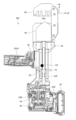
- FIG. 2 is a partially cutaway side view showing the inside of the electric cutting machine shown in FIG. 1, seen from the left side.
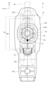
- FIG. 2 is a cross-sectional view (cross-sectional view taken along the line 3-3 in FIG. 1) seen from the rear side, showing an enlarged view of the intermediate portion in the front-rear direction of the grip shown in FIG. 1;
- FIG. 7 is an explanatory diagram for explaining the inclination of an electric cutting machine of a comparative example in which the center of gravity is shifted in an upright position.
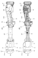
- FIG. 7 is a side view from the left side showing the interior and center of gravity of the electric cutting machine according to the second embodiment.
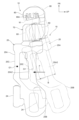
- FIG. 7 is a perspective view of the electric cutting machine shown in FIG. 6;
- A) is a side view from the left side showing the interior and center of gravity position of the electric cutting machine according to the third embodiment, and
- B) is a schematic diagram of the connecting part of the electric cutting machine of (A) seen from the front side.
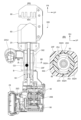
- FIG. 8B is a cross-sectional view (a cross-sectional view taken along line 8B-8B in FIG. 8(A)).
- FIG. 9 is a perspective view of the electric cutting machine shown in FIG. 8; It is a side view from the left side showing the interior and center of gravity position of an electric cutting machine according to a fourth embodiment.
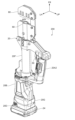
- FIG. 11 is a perspective view of the electric cutting machine shown in FIG. 10.
- FIG. It is a side view from the left side showing the interior and center of gravity position of an electric cutting machine according to a fifth embodiment.
- 13 is a perspective view of the electric cutting machine shown in FIG. 12.
- FIG. (A) is a side view of the electric cutting machine according to the sixth embodiment, seen from the left side, and (B) is a side view of the inside of the electric cutting machine of (A), seen from the left side.
- (A) is a side view of the electric cutting machine according to the seventh embodiment, seen from the left side, and (B) is a side view of the inside of the electric cutting machine of (A), seen from the left side.
- (A) is a side view of the electric cutting machine according to the eighth embodiment, seen from the left side
- (B) is a side view of the inside of the electric cutting machine of (A), seen from the left side
- (A) is a side view of the electric cutting machine according to the ninth embodiment, seen from the left side
- (B) is a side view of the inside of the electric cutting machine of (A), seen from the left side
- (A) is a side view of the electric cutting machine according to the tenth embodiment, seen from the left side
- (B) is a side view of the inside of the electric cutting machine of (A), seen from the left side.
- FIGS. 1 to 5 An electric cutting machine 10 as a working machine according to a first embodiment will be described below with reference to FIGS. 1 to 5.
- arrows UP, FR, and LH shown as appropriate in the drawings indicate the upper side, the front side, and the left side of the electric cutting machine 10, respectively.
- the up-down direction, front-back direction, and left-right direction of the electric cutting machine 10 are meant.
- the front-rear direction corresponds to the first direction of the present invention
- the up-down direction corresponds to the second direction of the present invention
- the left-right direction corresponds to the third direction of the present invention.
- the electric cutting machine 10 is configured as an electric tool that cuts a workpiece W, which is a light ceiling material used for a suspended ceiling of a building.
- This workpiece W is formed in the shape of a long column, and is formed into a substantially U-shape when viewed from its longitudinal direction.
- the light sheet material is made of metal, and naturally its cross section (in the direction perpendicular to the longitudinal direction) is also approximately U-shaped.
- the electric cutting machine 10 includes a housing 20, a motor 40, a feed screw mechanism 50 (in a broad sense, it is an element understood as a moving mechanism), a blade 60 as a cutting tool, a guide mechanism 70, and a controller 90. It is composed of and. Each configuration of the electric cutting machine 10 will be described below.
- the housing 20 constitutes the outer shell of the electric cutting machine 10, and extends in the front-rear direction as a whole.
- the housing 20 includes a handle housing part 20A that constitutes the front part of the housing 20, and a motor housing part 20B that constitutes the rear part of the housing 20.
- the handle housing portion 20A is formed into a substantially rectangular cylindrical shape extending in the front-rear direction.
- a pair of overhanging portions 20A1 are formed at the front end of the handle housing portion 20A, the overhanging portions 20A1 extending to both sides in the vertical direction.
- a handle guard 20C as a guard part is provided on the lower side of the handle housing part 20A.
- the handle guard 20C is formed into a substantially rectangular cylindrical shape extending in the front-rear direction.
- the front end of the handle guard 20C is bent upward and connected to the lower protrusion 20A1, and the rear end of the handle guard 20C is bent upward diagonally to the rear and connected to the rear of the handle housing 20A. connected to the end.
- a portion of the handle housing portion 20A between the front end and the rear end of the handle guard 20C is configured as a grip portion 20A2 that is gripped by the operator. That is, the grip portion 20A2 extends in the front-rear direction on the rear side of the overhang portion 20A1.
- the left-right dimension of the front end of the handle housing part 20A having the pair of overhanging parts 20A1 is set larger than the left-right dimension of the grip part 20A2, so that the front end of the handle housing part 20A is larger than the grip part 20A2. It projects outward from the portion 20A2 in the left-right direction (see FIG. 3).
- the motor housing portion 20B is formed into a substantially flat shape with the thickness direction being in the left-right direction.
- the thickness dimension of the motor housing part 20B is set larger than the thickness dimension (dimension in the left-right direction) of the handle housing part 20A.
- the upper end of the motor housing part 20B projects upwardly than the handle housing part 20A, and the lower end of the motor housing part 20B is located above the handle guard 20C.
- a trigger 30 as an operation section for instructing the start of movement of the blade 60 (start of cutting), which will be described later, is provided at the front end of the gripping section 20A2.
- the trigger 30 protrudes downward from the grip portion 20A2 and can be pulled upward.
- a trigger switch 32 is provided below the trigger 30 at the front end of the handle housing portion 20A. When the trigger 30 is pulled, the trigger switch 32 is switched from off to on. Note that by releasing the pull operation on the trigger 30, the trigger switch 32 is switched from on to off.
- the trigger switch 32 is electrically connected to a controller 90, which will be described later, and the controller 90 is housed in the rear end of the motor housing section 20B. Then, when the trigger switch 32 is turned on, the trigger switch 32 outputs an on signal to the controller 90.
- a battery mounting portion 20D serving as a battery mounting portion is provided at the lower end of the motor housing portion 20B on the rear side of the handle guard 20C.
- the battery mounting section 20D is provided with a battery terminal 22 as a power supply section for supplying power to the motor 40, and the battery terminal 22 is electrically connected to a controller 90, which will be described later.
- a battery 24 is detachably attached to the battery attachment portion 20D, and the battery 24 has a connector (not shown) that is connected to the battery terminal 22. Thereby, electric power is supplied to the motor 40, which will be described later, via the controller 90. Further, the position of the lower end of the battery 24 in the vertical direction matches the position of the lower end of the handle guard 20C.
- the battery 24 is set so as not to protrude below the handle guard 20C. Further, the rear end portion of the motor housing portion 20B protrudes to the rear side beyond the battery 24 and is curved in a substantially arc shape convex to the rear side when viewed from the side.
- a sub-trigger 34 (in a broad sense, an element understood as an erroneous operation suppressing section) for suppressing erroneous operation of the trigger 30 is provided at the upper end of the motor housing section 20B.
- the sub-trigger 34 is configured to be slidable to the front.
- a sub-trigger switch 36 is provided in the upper end of the motor housing part 20B below the sub-trigger 34, and the sub-trigger switch 36 is electrically connected to a controller 90, which will be described later. Then, by sliding the sub-trigger 34, the sub-trigger switch 36 is switched from off to on, and outputs an on signal to the controller 90.
- the electric cutting machine 10 is configured such that normal rotation of the motor 40, which will be described later, is permitted by turning on the trigger switch 32 after turning on the sub-trigger switch 36 at the start of the cutting process. That is, the sub-trigger 34 is configured as an operation section for suppressing erroneous operation of the trigger 30 at the start of cutting.
- An inner guide 38 is provided at the front end of the handle housing portion 20A, and the inner guide 38 is formed in a substantially cylindrical shape with the front-rear direction as the axial direction.
- the rear part of the inner guide 38 is supported by the handle housing part 20A, and the front part of the inner guide 38 projects forward from the handle housing part 20A.
- a pair of upper and lower slits 38A are formed in the front portion of the inner guide 38 for arranging a blade 60, which will be described later.
- the slit 38A extends in the front-back direction and penetrates in the vertical direction, and the front end of the slit 38A is open to the front side.
- the motor 40 is configured as a brushless motor and is housed in the front part of the motor housing part 20B.
- the motor 40 has a drive shaft 40A whose axial direction extends in the front-rear direction.
- the rear end of the drive shaft 40A is rotatably supported by a motor bearing 42 held in the housing 20, and the front end of the drive shaft 40A
- the side portions are rotatably supported on motor bearings 44 held in the housing 20.
- a pinion gear 40B is formed at the front end of the drive shaft 40A.
- the motor 40 is electrically connected to a controller 90 and is driven under the control of the controller 90.
- the feed screw mechanism 50 includes a transmission gear 51, a drive shaft 53 (in a broad sense, an element understood as an output shaft), and a lifter 55 (in a broad sense, an element understood as a moving member).
- the lifter detection switch 58 is configured to include a lifter detection switch 58 (in a broad sense, an element understood as an initial position detection section) for detecting the initial position of the lifter 55.
- the transmission gear 51 is formed in a substantially stepped cylindrical shape with the longitudinal direction as the axial direction, and the diameter of the front part of the transmission gear 51 is set larger than the diameter of the rear part of the transmission gear 51.
- a gear recess 51A that is open toward the front is formed in the center of the front surface of the transmission gear 51.
- the transmission gear 51 is arranged below the front end of the drive shaft 40A of the motor 40, and the rear part of the transmission gear 51 is rotatably supported by a gear bearing 52 held in the housing 20.
- a gear portion 51B is formed on the outer peripheral portion of the front portion of the transmission gear 51, and the gear portion 51B is meshed with the pinion gear 40B of the drive shaft 40A.
- the drive shaft 53 is formed in a substantially cylindrical shape with an axial direction extending in the front-rear direction.
- the drive shaft 53 is housed in the handle housing portion 20A, and is disposed in front of the transmission gear 51 and coaxially with the transmission gear 51.
- the rear end portion of the drive shaft 53 is fitted into the gear recess 51A of the transmission gear 51 so as to be able to rotate integrally therewith, and the rear end portion of the drive shaft 53 is rotated by a shaft bearing 54 held in the housing 20. Possibly supported.
- the motor 40 is driven, and the drive shaft 53 is rotated.
- a male thread 53A is formed on the outer circumference of the drive shaft 53 except for the rear end.
- the lifter 55 is generally formed into a substantially elongated shape extending in the front-rear direction.
- the lifter 55 includes a lifter main body 56 and a lifter connecting portion 57 that constitutes a rear end portion of the lifter 55.
- the lifter connecting portion 57 is formed into a substantially stepped cylindrical shape with the longitudinal direction being the axial direction.
- a female thread 57A is formed on the inner peripheral portion of the rear portion of the lifter connecting portion 57.
- the front portion of the drive shaft 53 is inserted into the lifter connection portion 57, and the male screw 53A of the drive shaft 53 and the female screw 57A of the lifter connection portion 57 are screwed together. That is, the drive shaft 53 and the lifter 55 are threadedly fitted.
- the lifter 55 As a result, as the drive shaft 53 rotates, the lifter 55 is moved in the front-rear direction. Specifically, the lifter 55 reciprocates between an initial position (the position shown by the solid line in FIG. 2) and a processing position (the position shown by the two-dot chain line in FIG. 2). Further, the outer peripheral portion of the rear end portion of the lifter connecting portion 57 is configured as a detected portion 57B.
- the lifter main body 56 is formed into a substantially bottomed cylindrical shape that is open to the rear side.
- the rear end portion of the lifter body 56 is fitted into the front portion of the lifter connecting portion 57, so that the lifter connecting portion 57 and the lifter body 56 are connected so as to be immovable relative to each other.
- the front portion of the drive shaft 53 is inserted into the lifter body 56 so as to be relatively movable.
- the front end portion of the lifter main body 56 is supported by an inner guide 38 provided at the front end portion of the handle housing portion 20A so as to be relatively movable in the front and rear direction.
- a lifter flange 56A is formed on the outer periphery of the rear end portion of the lifter body 56, and the lifter flange 56A is formed in the shape of a disk that protrudes outward in the radial direction of the lifter body 56.
- the lifter flange 56A is arranged close to the rear side of the inner guide 38.
- the lifter detection switch 58 is configured as a lever-type microswitch and is housed in the rear end of the handle guard 20C.
- a spherical ball 59 is provided above the lifter detection switch 58, and the ball 59 is placed in a ball hole 20E formed at the lower end of the outer circumference of the handle housing portion 20A.
- the ball hole 20E penetrates in the vertical direction, and the diameter of the ball hole 20E increases toward the bottom.
- the detected portion 57B of the lifter 55 presses the ball 59 radially outward (downward), and the ball 59 moves toward the lifter detection switch 58 (downward). Displace. That is, when the lifter 55 reaches the initial position while moving from the processing position to the initial position, the ball 59 presses the lever portion of the lifter detection switch 58, turning the lifter detection switch 58 from off to on. It is set to switch to .
- the lifter detection switch 58 is electrically connected to the controller 90 and outputs a detection signal to the controller 90.
- the blade 60 is formed into a plate shape extending vertically and forwardly, with the thickness direction being the left-right direction.
- the rear end of the blade 60 is fixed to the front end of the lifter 55 with a screw 61.
- the blade 60 is configured to be movable together with the lifter 55 between the initial position and the processing position.
- the rear end portion of the blade 60 is inserted into the slit 38A of the inner guide 38.
- a blade portion 60A for cutting the workpiece W is formed at the front end of the blade 60, and the blade portion 60A is configured as a single edge and has a substantially convex shape toward the front when viewed from the left and right direction. It is formed in a V-shape.
- the blade 60 In the initial position of the blade 60, the blade 60 is arranged adjacent to the front side of the housing 20 and is also arranged at the rear side of the workpiece W, and as the blade 60 moves from the initial position to the front side, the workpiece A cutting process is performed on the material W. Further, at the processing position of the blade 60, the cutting processing on the workpiece W is set to be completed.
- the guide mechanism 70 includes a blade holder 72, a connecting member 76, and a head section 80 as a processing section.
- the head section 80 functions as a member (supporting section) that supports the workpiece W.
- the workpiece W as a lightweight material may be fixed to a specific location (wall, ceiling, etc.), but in the present invention, the workpiece W in such a fixed state and the head portion 80
- the state in which the head portion 80 is engaged also means that the workpiece W is supported by the head portion 80.
- the blade holder 72 has a pair of left and right holder plates 74.
- the holder plate 74 is made of a metal plate and is formed into a substantially rectangular plate shape with the thickness direction being in the left-right direction.
- a fixing portion 74A is formed in the vertically intermediate portion of the holder plate 74, and the fixing portion 74A is formed in a substantially arc shape convex outward in the left-right direction when viewed from the front side.
- the fixing portion 74A is disposed on the radially outer side of the inner guide 38, and is fastened and fixed to the inner guide 38 by a pair of front and rear bolts BL1. Thereby, the holder plate 74 is fixed to the inner guide 38.
- the pair of holder plates 74 are arranged to face each other with a predetermined gap in the left-right direction.
- the opposing distance between the pair of holder plates 74 at the bottom is set to be slightly longer than the plate thickness of the blade 60, and the blade 60 is arranged between the pair of holder plates 74.
- the connecting member 76 is made of a metal plate, and is formed into a substantially elongated plate shape with the left-right direction as the thickness direction and extending in the front-rear direction.
- the connecting member 76 is disposed between the upper ends of the pair of holder plates 74, and is fastened and fixed to the holder plates 74 by bolts BL2.
- the head section 80 has a pair of left and right head plates 82.
- the head plate 82 is made of a metal plate material, and is formed in a plate shape with the left-right direction as the thickness direction.
- the pair of head plates 82 are arranged on the front side of the holder plate 74 and on the outer side in the left-right direction of the connecting member 76, and the upper end of the head plate 82 is fastened and fixed to the front end of the connecting member 76 by a bolt BL2. .
- the pair of head plates 82 are disposed facing each other with a predetermined interval in the left-right direction.
- a support portion 80A for supporting the workpiece W is formed at the rear end of the head portion 80, and the support portion 80A has a substantially comb-like shape with the vertical direction as the width direction and opening toward the rear side. It is formed. That is, a plurality of notches 80A1 (in this embodiment, four locations) that are open to the rear side are formed through the support portion 80A, and the plurality of notches 80A1 are formed in a predetermined width direction in the width direction of the support portion 80A. They are placed side by side with space between them.
- both ends of the workpiece W viewed from the longitudinal direction of the workpiece W are inserted into the notch 80A1, and the workpiece W is set (supported) in the head section 80. It looks like this.
- the workpiece W is supported by the head section 80, with a portion of the workpiece W being positioned in the notch 80A1.
- the notches 80A1 are provided at four locations, it is possible to cut a workpiece W having a width corresponding to the combination of recesses.
- the entire gripping portion 20A2 of the housing 20 is arranged at a position overlapping the supporting portion 80A of the head portion 80 in the vertical direction (same position in the vertical direction). That is, when viewed from the left and right direction, the grip portion 20A2 is disposed within the range of the width dimension A (see FIG. 1) of the comb-shaped support portion 80A, and extends in the front-rear direction. In other words, the grip part 20A2 and the support part 80A overlap when viewed from the front and rear directions, and the grip part 20A2 is arranged directly behind the support part 80A (guide mechanism 70) (see FIG. 3).
- the width dimension A is the range from one end in the predetermined direction to the other end of the plurality of notches 80A1 arranged in the predetermined direction (vertical direction). Further, the width dimension A of the support portion 80A is set to be slightly smaller than the width dimension B (vertical dimension) of the blade 60, and when viewed from the left and right, the support portion 80A is set to be slightly smaller than the width dimension B of the blade 60. located within range. Furthermore, the tip portion 60B of the blade portion 60A of the blade 60 is arranged at a position offset upward from the vertical center portion 80A2 of the support portion 80A in side view (see FIG. 1).
- a portion of the trigger 30 of the housing 20 is arranged at a position overlapping the support portion 80A in the vertical direction (see FIG. 3). That is, when viewed from the left-right direction, a portion of the trigger 30 is disposed within the width dimension A of the support portion 80A and extends in the front-rear direction. In other words, a portion of the trigger 30 and the support portion 80A overlap when viewed from the front and rear directions (see FIG. 3).
- the controller 90 is housed in the rear end of the motor housing portion 20B of the housing 20 and is held by the housing 20.
- the trigger switch 32, sub-trigger switch 36, motor 40, and lifter detection switch 58 are electrically connected to the controller 90.
- the controller 90 detects the initial position of the lifter 55 based on the detection signal of the lifter detection switch 58. Further, the controller 90 drives and controls the motor 40 based on output signals from the trigger switch 32, the sub-trigger switch 36, and the lifter detection switch 58. Then, the controller 90 drives the motor 40 in the forward direction, so that the lifter 55 (blade 60) moves forward, and the controller 90 drives the motor 40 in the reverse direction, so the lifter 55 (blade 60) moves backward. It is supposed to move.
- the controller 90 is configured to drive the motor 40 in the reverse direction when the operation of the trigger 30 is released and the trigger switch 32 is switched from on to off while the motor 40 is being driven in the normal direction. Further, the controller 90 includes a motor drive detection section 90A that detects the rotation speed of the drive shaft 40A of the motor 40. The controller 90 detects how many revolutions the motor 40 has made from the initial position based on the detection signal from the motor drive detection section 90A. Thereby, the controller 90 detects the processing position of the lifter 55 (blade 60) based on the rotation speed of the motor 40 starting from the initial position of the lifter 55. Furthermore, when the controller 90 detects the processing position of the lifter 55 (blade 60), it stops driving the motor 40.
- the center of gravity G1 of the electric cutting machine 10 is located within the width dimension B of the blade 60 when viewed from the side. That is, the center of gravity G1 is located at a position overlapping the blade 60 in the vertical direction. Specifically, the center of gravity G1 is located on the rear side of the trigger 30 in a side view, and at a position overlapping the lower end portion of the grip portion 20A2 in the approximately central portion in the front-rear direction. That is, in the vertical direction, the center of gravity G1 is located at a position offset downward from the center portion 80A2 of the support portion 80A.
- the center of gravity G1 overlaps with the lower end portion of the gripping portion 20A2 in the approximately central portion in the front-rear direction, so that the rear portion of the gripping portion 20A2 is centered on the center portion 80A2 of the support portion 80A. Moreover, it is located outside the virtual circle CR passing through the center of gravity G1. Furthermore, as shown in FIG. 3, the center of gravity G1 of the electric cutting machine 10 is located at the center of the electric cutting machine 10 in the left-right direction. That is, the center of gravity G1 overlaps the blade 60 and the support portion 80A when viewed from the front and rear directions.
- FIG. 4 shows a flowchart of the electric cutting machine 10.
- the controller 90 determines whether the sub-trigger switch 36 is on based on the output signal from the sub-trigger switch 36. Detect. That is, the controller 90 determines whether the sub-trigger switch 36 has been operated. In step 1, if the sub-trigger switch 36 is not turned on (No in step 1), the process returns to step 1. If the sub-trigger switch 36 is turned on in step 1 (Yes in step 1), the process moves to step 2 (S2).
- step 2 based on the output signal from the trigger switch 32, it is detected whether the trigger switch 32 is on. That is, the controller 90 determines whether the trigger 30 is operated while the sub-trigger switch 36 is on. In step 2, if the trigger switch 32 is not turned on (No in step 2), the process returns to step 1. In step 2, if the trigger switch 32 is turned on (Yes in step 2), the process moves to step 3 (S3). In addition, after step 3, even if the sub-trigger switch 36 is switched from on to off, the operation of the electric cutting machine 10 is continued.
- step 3 the controller 90 detects whether the lifter detection switch 58 is turned on based on the output signal from the lifter detection switch 58. That is, the controller 90 determines whether the lifter 55 is placed at the initial position. In step 3, if the lifter detection switch 58 is on (Yes in step 3), the process moves to step 4 (S4).
- step 4 the controller 90 causes the motor 40 to rotate forward. That is, when the controller 90 detects the initial position of the lifter 55, it drives the motor 40 in the normal rotation. As a result, the lifter 55 and the blade 60 move forward (toward the forward path side), and the blade 60 approaches the workpiece W. After the processing in step 4, the process moves to step 5 (S5).
- step 5 the controller 90 detects whether the trigger switch 32 continues to be in the on state based on the output signal from the trigger switch 32. That is, the controller 90 determines whether the operation on the trigger 30 is continued. In step 5, if the trigger switch 32 continues to be in the on state (Yes in step 5), the process moves to step 6 (S6).
- step 6 the controller 90 detects whether the lifter detection switch 58 has been switched from on to off based on the output signal from the lifter detection switch 58. If the lifter detection switch 58 is turned off in step 6 (Yes in step 6), the process moves to step 7 (S7). That is, in this embodiment, the position of the lifter 55 at which the lifter detection switch 58 is switched from on to off is the starting point at the initial position of the lifter 55 moving forward (hereinafter, this position of the lifter 55 is referred to as the initial starting position). In step 6, the controller 90 detects the initial starting position of the lifter 55. On the other hand, if the lifter detection switch 58 has not been turned off in step 6 (No in step 6), the process returns to step 5. That is, if the lifter 55 moving outward at the initial position has not reached the initial starting position, the process returns to step 5.
- step 7 the controller 90 starts measuring the rotational speed of the motor 40. Specifically, the controller 90 starts measuring (counting) the number of revolutions of the motor 40 based on a signal from the motor drive detection section 90A. After the processing in step 7, the process moves to step 8 (S8).
- step 8 the controller 90 detects whether the trigger switch 32 continues to be in the on state based on the output signal from the trigger switch 32. That is, the controller 90 determines whether the operation of the trigger 30 is continued. In step 8, if the trigger switch 32 continues to be in the on state (Yes in step 8), the process moves to step 9 (S9).
- step 9 the controller 90 determines whether the number of rotations of the motor 40 has reached a predetermined number of rotations or more. That is, the controller 90 determines whether the lifter 55 has reached the processing position. In step 9, if the rotation speed of the motor 40 is not equal to or higher than the predetermined rotation speed (No in step 9), the process returns to step 8. In step 9, if the rotation speed of the motor 40 is equal to or higher than the predetermined rotation speed (Yes in step 9), the process moves to step 10 (S10).
- step 10 the controller 90 stops the normal rotation of the motor 40. After the processing in step 10, the process moves to step 11 (S11).
- step 11 the motor 40 is put into a standby state. That is, after the normal rotation of the motor 40 is stopped, the controller 90 does not control the drive of the motor 40, and the motor 40 is placed in a standby state.
- step 12 the process moves to step 12 (S12). Specifically, after a predetermined period of time has elapsed after the normal rotation of the motor 40 is stopped, the process moves to step 12.
- step 12 based on the output signal from the trigger switch 32, it is detected whether the trigger switch 32 is on. In step 12, if the trigger switch 32 is not turned on (No in step 12), the process returns to step 12. In step 12, if the trigger switch 32 is turned on (Yes in step 12), the process moves to step 13 (S13).
- step 13 the controller 90 drives the motor 40 in the reverse direction. As a result, the lifter 55 and the blade 60 move rearward (return path side) and separate from the workpiece W. That is, the lifter 55 and the blade 60 are reversed at the processing position, and the return movement of the lifter 55 and the blade 60 is started. After the processing in step 13, the process moves to step 14 (S14).
- step 14 the controller 90 detects whether the lifter detection switch 58 is turned on based on the output signal from the lifter detection switch 58. That is, the controller 90 determines whether the lifter 55 has reached the initial position. In step 14, if the lifter detection switch 58 is not on (No in step 14), the process returns to step 14. On the other hand, if the lifter detection switch 58 is on in step 14 (Yes in step 14), the process moves to step 15 (S15).
- step 15 the reverse rotation of the motor 40 by the controller 90 is stopped. This causes the lifter 55 to stop at the initial position. After the processing in step 15, the process moves to step 16 (S1).
- step 16 the controller 90 detects whether the trigger switch 32 has been switched from on to off based on the output signal from the trigger switch 32. That is, the controller 90 detects whether the operation of the trigger 30 is released. In step 16, if the trigger switch 32 is not off (No in step 16), the process returns to step 16. On the other hand, if the trigger switch 32 is off in step 16 (Yes in step 16), the operation of the electric cutting machine 10 is ended because the trigger 30 has been released.
- step 3 if the lifter detection switch 58 is not on (No in step 3), the process moves to step 13. That is, in this case, since the lifter 55 has not returned to the initial position when the electric cutting machine 10 starts operating, the process moves to step 13 and the lifter 55 is returned to the initial position.
- Step 17 the controller 90 stops the normal rotation of the motor 40, and after stopping the normal rotation of the motor 40, the process moves to step 18.
- the center of gravity G1 of the electric cutting machine 10 is located at a position overlapping the blade 60 in the vertical direction of the electric cutting machine 10 when viewed from the side. That is, the center of gravity G1 of the electric cutting machine 10 is located within the width dimension B of the blade 60 in the vertical direction when viewed from the side. Therefore, in the upright position of the electric cutting machine 10, the center of gravity G1 of the electric cutting machine 10 is located vertically below the blade 60 for cutting the workpiece W. Thereby, the workability of the electric cutting machine 10 can be improved.
- this electric cutting machine 10 of the comparative example When the electric cutting machine 10 of the comparative example is placed in the standing position, the center of gravity G1 is positioned vertically downward with respect to the workpiece W, so that the electric cutting machine 10 of the comparative example tends to tilt with respect to the vertical direction. For example, as shown by the two-dot chain line in FIG. The electric cutting machine 10 of the comparative example is tilted so as to be located on the lower side. Therefore, it is necessary for the operator to apply a horizontal force F (see FIG. 5) to correct the posture of the electric cutting machine 10 of the comparative example to the standing posture shown by the solid line. For this reason, in the electric cutting machine 10 of the comparative example, there is a possibility that workability may be reduced.
- a horizontal force F see FIG. 5
- the center of gravity G1 is located within the width dimension B of the blade 60 in the vertical direction, as described above. Therefore, during cutting in an upright position, the electric cutting machine 10 naturally assumes an upright position along the vertical direction. Thereby, the inclination of the blade 60 with respect to the workpiece W can be suppressed. As a result, there is no need to correct the posture as in the electric cutting machine 10 of the comparative example. Therefore, according to the electric cutting machine 10 of this embodiment, workability can be improved.
- the grip portion 20A2 of the housing 20 is arranged at a position overlapping the center of gravity G1 in the front-rear direction.
- the center of gravity G1 overlaps with the lower end portion of the grip portion 20A2 at the approximately central portion in the front-rear direction. That is, in the present embodiment, the center of gravity G1 is located at a position overlapping the grip portion 20A2 in the front-back direction and the up-down direction. Therefore, cutting can be performed by holding the gripping portion 20A2 where the center of gravity G1 is located.
- the burden on the operator for maintaining the electric cutting machine 10 in the standing position can be reduced. As a result, the workpiece W can be easily inserted between the blade holder 72 and the head section 80. With the above, the workability of the electric cutting machine 10 can be further improved.
- the grip portion 20A2 is arranged at a position overlapping the center of gravity G1 in the front-back direction, and extends in the front-back direction. For this reason, for example, the posture of the electric cutting machine 10 when the operator grips the grip part 20A2 of the electric cutting machine 10 in the horizontal posture (the posture in which the front-rear direction of the electric cutting machine 10 is aligned with the horizontal direction). Able to maintain good balance. Thereby, for example, the transportability of the electric cutting machine 10 in a horizontal position can be improved.
- the tip portion 60B of the blade portion 60A of the blade 60 is arranged at a position offset upward from the center portion 80A2 in the width direction of the support portion 80A, and the center of gravity G1 is located at the center portion 80A2 in the width direction of the support portion 80A. It is offset downward from . This makes it easier to ensure a distance from the tip 60B or the screw 61 (the connection between the blade 60 and the lifter 55) that receives the reaction force to the center of gravity G1. By moving the center of gravity away from the position where the reaction force is generated, it is possible to suppress rotation of the electric cutting machine 10 when the reaction force is generated.
- the rear part of the grip part 20A2 is located outside the virtual circle CR that is centered on the center part 80A2 in the width direction of the support part 80A and passes through the center of gravity G1.
- the workability of the electric cutting machine 10 can be further improved. That is, for example, when setting a workpiece W as a light material on the electric cutting machine 10 in an upright position, the workpiece W is set so as to be hooked on the support portion 80A. At this time, the force F exerted by the operator on the grip part 20A2 may generate a moment centered on the support part 80A and cause the grip part 20A2 to be hooked.
- the operator by gripping the grip part 20A2 which is spaced apart from the center of gravity G1 with respect to the support part 80A, the operator generates the moment with a relatively small force F and pulls the workpiece W to the support part 80A. It can be set to hang. Therefore, the workability of the electric cutting machine 10 can be further improved.
- a motor 40 is accommodated in the motor housing portion 20B of the housing 20, and the motor 40 is arranged at a position offset upward from a center portion 80A2 in the width direction of the support portion 80A in the head portion 80.
- the housing 20 extends in the front-rear direction
- the grip portion 20A2 constitutes the front side portion of the housing
- the motor housing portion 20B constitutes the rear portion of the housing 20.
- the rear end of the feed screw mechanism 50 for reciprocating the blade 60 by the driving force of the motor 40 and the front end of the motor 40 can be arranged so as to overlap in the front-rear direction and accommodated in the housing 20. I can do it. Therefore, it is possible to contribute to reducing the size of the electric cutting machine 10 in the front-rear direction.
- the motor housing portion 20B is provided with a battery mounting portion 20D for mounting the battery 24, and the battery mounting portion 20D is provided below the motor 40. Further, the battery mounting portion 20D is provided with a battery terminal 22 for supplying power to the motor 40. Thereby, the battery 24 that supplies power to the motor 40 can be attached to the housing 20 while suppressing the increase in the size of the electric cutting machine 10 in the front-rear direction.
- the entire gripping portion 20A2 is arranged at a position overlapping the supporting portion 80A in the vertical direction. That is, the grip part 20A2 is arranged on the rear side of the head part 80, and the grip part 20A2 and the support part 80A overlap when viewed from the front and back direction. Therefore, when the electric cutting machine 10 is in the upright position, the grip portion 20A2 is arranged directly below the support portion 80A in the vertical direction. Thereby, when setting the workpiece W, which is a lightweight material fixed to the ceiling or the like, in the electric cutting machine 10, the position of the support part 80A (head part 80) can be easily grasped.
- a trigger 30 is provided on the grip portion 20A2, and a portion of the trigger 30 overlaps with the support portion 80A when viewed from the front and rear directions. Thereby, the trigger 30 can be operated with the hand holding the grip part 20A2 while maintaining the state in which the operator's hand is placed directly behind the support part 80A. Therefore, the workability of the electric cutting machine 10 can be further improved.
- the housing 20 has a handle guard 20C extending in the front-rear direction, and the handle guard 20C is disposed below the grip portion 20A2 and in front of the battery mounting portion 20D. That is, in the front-rear direction, the handle guard 20C is arranged at a position overlapping the center of gravity G1.
- the handle guard 20C is placed on the ground or the like with the electric cutting machine 10 in a horizontal position, it is possible to stabilize the placement state of the electric cutting machine 10. As a result, for example, the storage state of the electric cutting machine 10 can be stabilized. Further, it becomes easy to perform cutting work with the electric cutting machine 10 placed horizontally.
- FIGS. 6 and 7 an electric cutting machine 200 as a working machine according to a second embodiment will be described using FIGS. 6 and 7.
- the electric cutting machine 200 of the second embodiment is configured similarly to the electric cutting machine 10 of the first embodiment except for the following points. Note that in FIGS. 6 and 7, members configured similarly to the electric cutting machine 10 of the first embodiment are denoted by the same reference numerals.
- the housing 20 includes a lifter housing portion 20F that constitutes a front end portion of the housing 20, a motor housing portion 20B that constitutes an intermediate portion of the housing 20 in the longitudinal direction, and a rear housing portion 20G that constitutes a rear portion of the housing 20. ing.
- the lifter housing portion 20F is formed into a substantially cylindrical shape extending in the front-rear direction, and the feed screw mechanism 50 is accommodated in the lifter housing portion 20F.
- a motor 40 is housed in the motor housing portion 20B, and the motor 40 is arranged at a position offset downward from the drive shaft 53 of the feed screw mechanism 50.
- a controller 90 is housed in the rear housing part 20G, and a battery mounting part 20D is provided at the rear end of the rear housing part 20G.
- the grip portion 20A2 is disposed above the lifter housing portion 20F and extends in the front-rear direction. Specifically, in a side view, the grip part 20A2 extends along a direction that is slightly inclined upward as it goes toward the front side, and the front end of the grip part 20A2 is bent downward to form the lifter housing part 20F. The rear end of the grip portion 20A2 is bent downward and connected to the motor housing portion 20B. A trigger 30 that protrudes downward is provided at the front end of the grip portion 20A2.
- the handle guard 20C is omitted in the housing 20, but the area around the trigger 30 is protected by being surrounded by the lifter housing part 20F and the grip part 20A2.
- the center of gravity G2 of the electric cutting machine 200 when viewed from the side, is located at a position overlapping the blade 60 and the support portion 80A in the vertical direction of the electric cutting machine 200. Specifically, in a side view, the center of gravity G2 overlaps with the lifter housing portion 20F, and is located within the width dimension B of the blade 60 and within the width dimension A of the support portion 80A in the vertical direction. . Therefore, in the upright position of the electric cutting machine 200, the center of gravity G2 of the electric cutting machine 200 is located below the blade 60 for cutting the workpiece W in the vertical direction. Thereby, similarly to the first embodiment, the workability of the electric cutting machine 200 can be improved.
- the grip portion 20A2 of the housing 20 is arranged at a position overlapping the center of gravity G2 in the front-rear direction. Therefore, in the longitudinal direction of the electric cutting machine 200, the cutting process can be performed by gripping the gripping portion 20A2 arranged at a position that substantially coincides with the center of gravity G2. Therefore, the workability of the electric cutting machine 200 can be further improved.
- the grip portion 20A2 is arranged at a position overlapping the center of gravity in the front-back direction, and extends in the front-back direction. Therefore, for example, when the operator grips the grip portion 20A2 of the electric cutting machine 200 in a horizontal position, the posture balance of the electric cutting machine 200 can be improved. Therefore, the transportability of the electric cutting machine 200 in a horizontal position can be improved.
- FIG. 8(A) shows a cross-sectional view similar to FIGS. 2 and 6, and FIG. 8(B) is a schematic cross-sectional view taken along line 8B-8B in FIG. 8(A).
- the electric cutting machine 300 of the third embodiment is configured in the same manner as the electric cutting machine 10 of the first embodiment except for the following points.
- the same reference numerals are attached to the members configured similarly to the electric cutting machine 10 of the first embodiment.
- the handle guard 20C is omitted in the housing 20, similar to the second embodiment.
- the housing 20 includes a lifter housing section 20F similar to that of the second embodiment, and a motor housing section 20B that constitutes the rear end of the housing 20.
- the lifter housing part 20F constitutes the front part of the housing 20, and the feed screw mechanism 50 is accommodated in the lifter housing part 20F.
- a motor 40 is accommodated in the motor housing portion 20B, and the motor 40 is arranged at a position offset upward from the drive shaft 53 of the feed screw mechanism 50.
- a battery mounting section 20D is provided at the lower end of the motor housing section 20B, and the battery 24 mounted on the battery mounting section 20D is disposed below the motor housing section 20B.
- the gripping portion 20A2 is disposed on the radially outer side of the lifter housing portion 20F and extends in a direction perpendicular to the front-rear direction (in the example shown in FIG. 9, the gripping portion 20A2 20F and extends in the left-right direction).
- the gripping portion 20A2 is connected to the lifter housing portion 20F by a connecting portion 302, and is configured to be rotatable in the circumferential direction of the lifter housing portion 20F.
- the connecting portion 302 is provided on the radially outer side of the lifter housing portion 20F, and both longitudinal ends of the gripping portion 20A2 are bent toward the lifter housing portion 20F and connected to the connecting portion 302. .
- the grip portion 20A2 extends in a direction perpendicular to the front-rear direction on the radially outer side of the lifter housing portion 20F, and is rotatably connected in the circumferential direction of the lifter housing portion 20F.
- a trigger 30 is provided at one end in the longitudinal direction of the grip portion 20A2, and the trigger 30 projects upward from the grip portion 20A2.
- the lifter housing portion 20F is provided with two convex portions 20H and two thinned portions 20J at rotational positions that differ by 180 degrees.
- the connecting portion 302 is provided with recesses 302H on its inner surface at 90 degree intervals.
- the rotational position of the grip portion 20A2 is fixed by the engagement between the convex portion 20H and the concave portion 302H.
- the convex portion 20H has a curved surface, and the portion supporting the convex portion 20H is elastically deformable by the thinned portion 20J. Therefore, when a predetermined torque or more is applied to the gripping portion 20A2, the convex portion 20H will change in diameter. It retreats inward in the direction and leaves the recess 302H.
- the grip part 20A2 is rotated as it is, the convex part 20H fits into the recess part 302H at a position 90 degrees apart, and the rotational position of the grip part 20A2 is fixed.
- the grip portion 20A2 is configured to be rotatable within a predetermined angular range (270 degrees) with respect to the lifter housing portion 20F by a locking structure (not shown). That is, the grip portion 20A2 can select four rotational positions at 90 degree intervals. The torque applied to the grip portion 20A2 required for changing the rotational position can be adjusted by the amount of thinning of the thinned portion 20J. In this manner, in the second embodiment, the position of the grip portion 20A2 is configured to be changeable, and workability can be improved.
- the center of gravity G3 of the electric cutting machine 300 when viewed from the side, is located at a position overlapping the blade 60 and the support portion 80A in the vertical direction of the electric cutting machine 200. Specifically, in a side view, the center of gravity G3 overlaps with the lifter housing portion 20F, and is located within the width dimension B of the blade 60 and within the width dimension A of the support portion 80A in the vertical direction. . Therefore, in the upright position of the electric cutting machine 300, the center of gravity G3 of the electric cutting machine 300 is located below the blade 60 for cutting the workpiece W in the vertical direction. Thereby, similarly to the first embodiment, the workability of the electric cutting machine 300 can be improved. Note that this center of gravity positional relationship is configured so as not to change even if the rotational position of the grip portion 20A2 is changed.
- FIGS. 10 and 11 an electric cutting machine 400 as a working machine according to a fourth embodiment will be described using FIGS. 10 and 11.
- the electric cutting machine 400 of the fourth embodiment is configured in the same manner as the electric cutting machine 10 of the first embodiment except for the following points.
- the same reference numerals are attached to the members configured similarly to the electric cutting machine 10 of the first embodiment.
- the handle guard 20C is omitted in the housing 20, similar to the second embodiment.
- the housing 20 includes a lifter housing section 20F similar to that of the second embodiment, and a motor housing section 20B that constitutes the rear end of the housing 20.
- the lifter housing part 20F constitutes the front part of the housing 20, and the feed screw mechanism 50 is accommodated in the lifter housing part 20F.
- a motor 40 is housed in the motor housing portion 20B, and the motor 40 is arranged at a position offset downward from the drive shaft 53 of the feed screw mechanism 50, similarly to the second embodiment.
- a battery mounting section 20D is provided at the upper end of the motor housing section 20B, and the battery 24 mounted on the battery mounting section 20D is arranged above the motor housing section 20B.
- the grip portion 20A2 extends in the vertical direction and extends downward from the front end side portion of the lifter housing portion 20F. That is, the grip portion 20A2 extends from the front end side portion of the lifter housing portion 20F to the outside in the radial direction of the lifter housing portion 20F.
- the battery 24 is not arranged on the rear side of the grip part 20A2, and the grip part 20A2 extends to the opposite side to the direction in which the battery 24 projects with respect to the housing 20.
- a trigger 30 protruding toward the front is provided at the upper end of the grip portion 20A2.
- the center of gravity G4 of the electric cutting machine 400 when viewed from the side, is located at a position overlapping the blade 60 and the support portion 80A in the vertical direction of the electric cutting machine 400. Specifically, in a side view, the center of gravity G4 overlaps with the lifter housing portion 20F, and is located within the width dimension B of the blade 60 and within the width dimension A of the support portion 80A in the vertical direction. . Therefore, in the upright position of the electric cutting machine 400, the center of gravity G4 of the electric cutting machine 400 is located below the blade 60 for cutting the workpiece W in the vertical direction. Thereby, similarly to the first embodiment, the workability of the electric cutting machine 400 can be improved.
- the gripping portion 20A2 of the housing 20 is arranged at a position overlapping the center of gravity G4 in the front-rear direction. Therefore, in the longitudinal direction of the electric cutting machine 400, the cutting process can be performed by gripping the gripping portion 20A2 arranged at a position that substantially coincides with the center of gravity G4. Therefore, the workability of the electric cutting machine 400 can be further improved.
- FIGS. 12 and 13 an electric cutting machine 500 as a working machine according to a fifth embodiment will be described using FIGS. 12 and 13.
- the electric cutting machine 500 of the fifth embodiment is configured similarly to the electric cutting machine 10 of the first embodiment except for the following points.
- FIG. 12 and FIG. 13 the same reference numerals are given to members configured similarly to the electric cutting machine 10 of the first embodiment.
- the handle guard 20C is omitted in the housing 20, similar to the second embodiment.
- the longitudinal dimension of the housing 20 is set shorter than in the first embodiment.
- the housing 20 includes a lifter housing section 20F similar to that of the second embodiment, and a motor housing section 20B disposed below the lifter housing section 20F.
- a feed screw mechanism 50 is accommodated in the lifter housing portion 20F.
- a motor 40 and a controller 90 are housed in the motor housing part 20B, and the motor 40 is arranged below and parallel to the feed screw mechanism 50.
- the controller 90 is placed in front of the motor 40.
- a battery mounting section 20D is provided above the rear end of the lifter housing section 20F, and the battery 24 mounted on the battery mounting section 20D is disposed above the motor housing section 20B.
- the grip portion 20A2 extends in the front-rear direction and is disposed above the lifter housing portion 20F and in front of the battery 24. Specifically, the grip portion 20A2 extends in a direction that is inclined upward as it goes toward the front side when viewed from the side. The front end of the grip part 20A2 is bent diagonally downward and connected to the front end of the lifter housing part 20F, and the rear end of the grip part 20A2 is bent downward and connected to the lifter housing part 20F. It is connected to the middle part in the front-rear direction. A trigger 30 that protrudes downward is provided at the front end of the grip portion 20A2.
- the center of gravity G5 of the electric cutting machine 500 when viewed from the side, is located at a position overlapping the blade 60 and the support portion 80A in the vertical direction of the electric cutting machine 500. Specifically, in a side view, the center of gravity G5 overlaps with the lifter housing portion 20F and is located within the width dimension B of the blade 60 and within the width dimension A of the support portion 80A in the vertical direction. . Therefore, in the upright position of the electric cutting machine 500, the center of gravity G5 of the electric cutting machine 500 is located below the blade 60 for cutting the workpiece W in the vertical direction. Thereby, similarly to the first embodiment, the workability of the electric cutting machine 500 can be improved.
- the gripping portion 20A2 of the housing 20 is arranged at a position overlapping the center of gravity G5 in the front-rear direction. Therefore, in the longitudinal direction of the electric cutting machine 500, the cutting process can be performed by gripping the gripping portion 20A2 arranged at a position that substantially coincides with the center of gravity G5. Therefore, the workability of the electric cutting machine 500 can be further improved.
- the motor housing part 20B is arranged below the lifter housing part 20F, and the grip part 20A2 and the battery 24 are arranged above the lifter housing part 20F, and are arranged side by side in the front-rear direction. has been done. Therefore, it is possible to reduce the size of the electric cutting machine 500 in the front-rear direction.
- FIGS. 14(A) and 14(B) an electric cutting machine 600 as a working machine according to a sixth embodiment will be described using FIGS. 14(A) and 14(B).
- the electric cutting machine 600 of the sixth embodiment is configured in the same manner as the electric cutting machine 10 of the first embodiment except for the following points. Note that in FIGS. 14A and 14B, members configured similarly to the electric cutting machine 10 of the first embodiment are denoted by the same reference numerals.
- the handle guard 20C is omitted in the housing 20.
- the longitudinal dimension of the housing 20 is set longer than that of the first embodiment.
- the housing 20 includes a lifter housing portion 20F that constitutes a front end portion of the housing 20, a motor housing portion 20B that constitutes an intermediate portion of the housing 20 in the longitudinal direction, and a handle housing portion 20A that constitutes a rear portion of the housing 20. ing.
- the lifter housing portion 20F is formed into a substantially cylindrical shape extending in the front-rear direction, and the feed screw mechanism 50 is accommodated in the lifter housing portion 20F.
- the motor 40 is housed in the motor housing part 20B, and the lower part of the motor housing part 20B protrudes below the lifter housing part 20F.
- the grip portion 20A2 constitutes the front portion of the handle housing portion 20A and extends in the front-rear direction.
- a lower portion of the rear end of the handle housing section 20A protrudes below the handle housing section 20A, and a battery mounting section 20D is provided at the rear end of the handle housing section 20A.
- the battery 24 mounted on the battery mounting portion 20D constitutes the rear end portion of the electric cutting machine 200.
- a controller 90 is housed in the rear end portion of the handle housing portion 20A.
- a trigger 30 is provided at the front end of the grip 20A2, and the trigger 30 projects downward from the front end of the grip 20A2. That is, in the electric cutting machine 600 of the sixth embodiment, the housing 20 protrudes further rearward than that of the first embodiment, and the grip portion 20A2 is arranged at the rear side of the motor 40.
- the center of gravity G6 of the electric cutting machine 600 when viewed from the side, is located at a position overlapping the blade 60 and the support portion 80A in the vertical direction of the electric cutting machine 600. Specifically, in side view, the center of gravity G6 overlaps with the lifter housing portion 20F, and is located within the width dimension B of the blade 60 and within the width dimension A of the support portion 80A in the vertical direction. . Therefore, in the upright position of the electric cutting machine 200, the center of gravity G6 of the electric cutting machine 200 is located below the blade 60 for cutting the workpiece W in the vertical direction. Thereby, similarly to the first embodiment, the workability of the electric cutting machine 600 can be improved.
- the gripping part 20A2 held by the operator is arranged on the rear side of the head part 80, and overlaps with the support part 80A of the head part 80 when viewed from the front and rear directions. Specifically, when viewed from the left and right direction, the grip portion 20A2 is disposed within the width dimension A of the support portion 80A and extends in the front and rear direction. In other words, when viewed from the left and right direction, the grip portion 20A2 is located at the same position as the support portion 80A in the vertical direction. Therefore, similarly to the first embodiment, when setting the workpiece W as a light workpiece fixed to the ceiling etc. in the electric cutting machine 600, the gripping part 20A2 is placed below the support part 80A in the vertical direction. will be done. As a result, the workpiece W can be easily set on the support section 80A of the head section 80. As described above, the workability of the electric cutting machine 600 can be improved.
- the trigger 30 is provided at the front end of the grip portion 20A2, and a portion of the trigger 30 overlaps with the support portion 80A when viewed from the front and rear directions. Specifically, a part of the trigger 30 is disposed within the range of the width dimension A of the support portion 80A when viewed from the left and right direction.
- the trigger 30 can be operated with the hand holding the grip part 20A2 while maintaining the state in which the operator's hand is placed on the rear side of the support part 80A. Therefore, the workability of the electric cutting machine 600 can be further improved.
- the housing 20 extends in the front-rear direction, and the motor housing part 20B, the grip part 20A2, and the battery mounting part 20D are arranged side by side in the front-rear direction.
- the grip portion 20A2 is arranged at the rear portion of the housing 20 (rear side of the central portion in the front-rear direction). Therefore, the grip portion 20A2 can be set on the rear end side of the electric cutting machine 600 while extending the physique of the electric cutting machine 600 in the front-back direction.
- the grip part 20A2 can be positioned lower in the vertical direction compared to the first embodiment. .
- the amount by which the operator lifts the electric cutting machine 600 can be reduced. Therefore, the workability of the electric cutting machine 600 can be further improved.
- FIGS. 15(A) and 15(B) an electric cutting machine 700 as a working machine according to a seventh embodiment will be described using FIGS. 15(A) and 15(B).
- the electric cutting machine 700 of the seventh embodiment is configured in the same manner as the electric cutting machine 10 of the first embodiment except for the following points. Note that in FIGS. 15A and 15B, members configured similarly to the electric cutting machine 10 of the first embodiment are denoted by the same reference numerals.
- the housing 20 includes a lifter housing part 20F similar to the sixth embodiment, a grip part 20A2 that constitutes an intermediate part of the housing 20 in the front-rear direction, and a motor housing part 20B that constitutes a rear end part of the housing 20. ing.
- the lifter housing portion 20F constitutes the front end portion of the housing 20, and the feed screw mechanism 50 is accommodated in the lifter housing portion 20F.
- a motor 40 is housed in the motor housing portion 20B.
- a battery mounting section 20D is provided at the rear end of the motor housing section 20B, and the battery 24 mounted on the battery mounting section 20D constitutes the rear end of the electric cutting machine 700. Accordingly, in the seventh embodiment, the lifter housing section 20F, the gripping section 20A2, the motor housing section 20B, and the battery mounting section 20D are arranged side by side in the front-back direction.
- the center of gravity G7 of the electric cutting machine 700 when viewed from the side, is located at a position overlapping the blade 60 and the support portion 80A in the vertical direction of the electric cutting machine 700. Specifically, in side view, the center of gravity G7 overlaps with the lifter housing portion 20F, and is located within the width dimension B of the blade 60 and within the width dimension A of the support portion 80A in the vertical direction. . Therefore, in the upright position of the electric cutting machine 700, the center of gravity G7 of the electric cutting machine 700 is located vertically below the blade 60 for cutting the workpiece W. Thereby, similarly to the first embodiment, the workability of the electric cutting machine 700 can be improved.
- the gripping part 20A2 held by the operator is arranged on the rear side of the head part 80 and overlaps with the support part 80A of the head part 80 when viewed from the front and back direction.
- substantially the entire grip portion 20A2 is disposed within the width dimension A of the support portion 80A, and extends in the front-rear direction.
- substantially the entire grip portion 20A2 is located at the same position as the support portion 80A in the vertical direction. Therefore, similarly to the first embodiment, when setting the workpiece W as a light workpiece fixed to the ceiling etc.
- the gripping part 20A2 is placed below the support part 80A in the vertical direction. will be done.
- the workpiece W can be easily set on the support section 80A of the head section 80.
- the workability of the electric cutting machine 700 can be improved.
- the trigger 30 is provided at the front end of the grip portion 20A2, and a portion of the trigger 30 overlaps the support portion 80A when viewed from the front and rear directions. Specifically, a part of the trigger 30 is disposed within the range of the width dimension A of the support portion 80A when viewed from the left and right direction.
- the trigger 30 can be operated with the hand holding the grip part 20A2 while maintaining the state in which the operator's hand is placed on the rear side of the support part 80A. Therefore, the workability of electric cutting machine 700 can be further improved.
- the housing 20 extends in the front-back direction, and the lifter housing part 20F, the grip part 20A2, the motor housing part 20B, and the battery mounting part 20D are arranged side by side in the front-back direction.
- the grip portion 20A2 is arranged at the rear portion of the housing 20 (rear side of the central portion in the front-rear direction). Therefore, similarly to the sixth embodiment, the grip portion 20A2 can be set on the rear end side of the electric cutting machine 700 while extending the physique of the electric cutting machine 700 in the front-back direction.
- the grip portion 20A2 can be positioned lower in the vertical direction than in the first embodiment. .
- the amount by which the operator lifts the electric cutting machine 700 can be reduced. Therefore, the workability of electric cutting machine 700 can be further improved.
- FIGS. 16(A) and 16(B) an electric cutting machine 800 as a working machine according to an eighth embodiment will be described using FIGS. 16(A) and 16(B).
- the electric cutting machine 800 of the eighth embodiment is configured in the same manner as the electric cutting machine 10 of the first embodiment except for the following points. Note that in FIGS. 16A and 16B, members configured similarly to the electric cutting machine 10 of the first embodiment are denoted by the same reference numerals.
- the housing 20 includes a lifter housing part 20F similar to the sixth embodiment and the seventh embodiment, a motor housing part 20B that constitutes an intermediate part in the front-rear direction of the housing 20, and a rear part of the housing 20. It has a handle housing part 20A constituting an end part.
- the lifter housing portion 20F constitutes the front end portion of the housing 20, and the feed screw mechanism 50 is accommodated in the lifter housing portion 20F.
- the motor housing section 20B protrudes downward from the rear end of the lifter housing section 20F, and the motor 40 is accommodated in the motor housing section 20B.
- a battery mounting portion 20D is provided at the rear end portion of the lifter housing portion 20F.
- the battery mounting portion 20D protrudes upward from the lifter housing portion 20F, and the battery 24 mounted on the battery mounting portion 20D protrudes above the battery mounting portion 20D.
- the handle housing portion 20A extends in a direction that slopes downward toward the rear side when viewed from the left side.
- the handle guard 20C extends rearward from the lower end of the motor housing section 20B, and the rear end of the handle guard 20C is connected to the lower end of the handle housing section 20A.
- a controller 90 is housed in the front end of the handle housing portion 20A.
- the center of gravity G8 of the electric cutting machine 800 when viewed from the side, is located at a position overlapping the blade 60 and the support portion 80A in the vertical direction of the electric cutting machine 800. Specifically, in side view, the center of gravity G8 overlaps with the lifter housing portion 20F, and is located within the width dimension B of the blade 60 and within the width dimension A of the support portion 80A in the vertical direction. . Therefore, in the upright position of the electric cutting machine 800, the center of gravity G8 of the electric cutting machine 800 is located below the blade 60 for cutting the workpiece W in the vertical direction. Thereby, similarly to the first embodiment, the workability of the electric cutting machine 800 can be improved.
- the front end portion of the gripping portion 20A2 held by the operator is disposed on the rear side of the head portion 80, and overlaps with the support portion 80A of the head portion 80 when viewed from the front and back direction.
- the front end portion of the gripping portion 20A2 when viewed from the left and right direction, is arranged within the range of the width dimension A of the support portion 80A, and the front end portion of the gripping portion 20A2 is inclined downward as the gripping portion 20A2 moves toward the rear side. It extends along.
- the front end portion of the grip portion 20A2 is located at the same position as the support portion 80A in the vertical direction.
- the front end of the gripping part 20A2 is vertically below the support part 80A. It will be placed on the side.
- the workpiece W can be easily set on the support section 80A of the head section 80 by the operator grasping the front end of the grip section 20A2.
- the workability of the electric cutting machine 800 can be improved.
- the grip portion 20A2 is inclined with respect to the front-rear direction, the weight of the head portion 80 facing upward can be received by the palm of the hand, resulting in a configuration that is less tiring.
- the trigger 30 is provided at the front end of the grip portion 20A2, and a portion of the trigger 30 overlaps with the support portion 80A when viewed from the front and rear directions. Specifically, a part of the trigger 30 is disposed within the range of the width dimension A of the support portion 80A when viewed from the left and right direction.
- the trigger 30 can be operated with the hand holding the grip part 20A2 while maintaining the state in which the operator's hand is placed on the rear side of the support part 80A. Therefore, the workability of electric cutting machine 800 can be further improved.
- the housing 20 extends in the front-rear direction, and the grip portion 20A2 constitutes the rear end portion of the housing 20. Therefore, when setting the workpiece W, which is a light material fixed to a ceiling or the like, in the electric cutting machine 800, the gripping part 20A2 can be positioned lower in the vertical direction than in the first embodiment. . As a result, the amount by which the operator lifts the electric cutting machine 800 can be reduced. Therefore, the workability of electric cutting machine 800 can be further improved.
- the motor housing part 20B and the battery mounting part 20D are arranged in the middle part of the housing 20 in the front-rear direction, and are arranged side by side in the vertical direction.
- the motor 40 and the battery 24 can be arranged centrally in the middle part of the housing 20 in the front-rear direction, and the grip part 20A2 can be set at the rear end part of the housing 20.
- FIGS. 17(A) and 17(B) an electric cutting machine 900 as a working machine according to a ninth embodiment will be described using FIGS. 17(A) and 17(B).
- the electric cutting machine 900 of the ninth embodiment is configured in the same manner as the electric cutting machine 10 of the first embodiment except for the following points. Note that in FIGS. 17A and 17B, members configured similarly to the electric cutting machine 10 of the first embodiment are denoted by the same reference numerals.
- the housing 20 extends in the front-rear direction, and the length of the housing 20 in the front-rear direction is set longer than in the first embodiment.
- the housing 20 includes a lifter housing part 20F similar to the eighth embodiment, a motor housing part 20B that constitutes an intermediate part of the housing 20 in the front-rear direction, and a grip part 20A2 that constitutes a rear end part of the housing 20. ing.
- the lifter housing portion 20F constitutes the front end portion of the housing 20, and the feed screw mechanism 50 is accommodated in the lifter housing portion 20F.
- the motor housing part 20B is arranged on the rear side of the lifter housing part 20F, and the lower part of the motor housing part 20B protrudes below the lifter housing part 20F, and the motor 40 is housed in the motor housing part 20B.
- a battery mounting portion 20D is provided at the rear end of the motor housing portion 20B, and the battery 24 protrudes rearward from the battery mounting portion 20D.
- a controller 90 is housed in the motor housing portion 20B.
- the gripping portion 20A2 is spaced apart from the battery 24 on the rear side and extends substantially in the vertical direction.
- the housing 20 has a pair of upper and lower handle guards 20C, and the handle guards 20C extend forward from both longitudinal ends of the grip portion 20A2 and are connected to the rear end of the motor housing portion 20B. .
- the center of gravity G9 of the electric cutting machine 900 when viewed from the side, is located at a position overlapping the blade 60 and the support portion 80A in the vertical direction of the electric cutting machine 900. Specifically, in a side view, the center of gravity G9 overlaps with the lifter housing portion 20F, and is located within the width dimension B of the blade 60 and within the width dimension A of the support portion 80A in the vertical direction. . Therefore, in the upright position of the electric cutting machine 900, the center of gravity G9 of the electric cutting machine 900 is located vertically below the blade 60 for cutting the workpiece W. Thereby, similarly to the first embodiment, the workability of the electric cutting machine 900 can be improved.
- the upper part of the grip part 20A2 held by the operator is arranged on the rear side of the head part 80, and overlaps with the support part 80A of the head part 80 when viewed from the front and back direction.
- the upper part of the grip part 20A2 when viewed from the left and right direction, is disposed within the width dimension A of the support part 80A, and the grip part 20A2 extends in the vertical direction.
- the upper part of the grip part 20A2 is located at the same position as the support part 80A in the vertical direction.
- the upper part of the gripping part 20A2 is positioned below the supporting part 80A in the vertical direction. It will be placed in As a result, the workpiece W can be easily set on the support part 80A of the head part 80 by the operator gripping the upper part of the grip part 20A2. As described above, the workability of the electric cutting machine 900 can be improved.
- the trigger 30 is provided at the upper end of the grip portion 20A2, and a portion of the trigger 30 overlaps with the support portion 80A when viewed from the front and rear directions. Specifically, when viewed from the left and right, a part of the trigger 30 is disposed within the width dimension A of the support section 80A (at the same position as the support section 80A in the vertical direction).
- the trigger 30 can be operated with the hand holding the grip part 20A2 while maintaining the state in which the operator's hand is placed on the rear side of the support part 80A. Therefore, the workability of the electric cutting machine 900 can be further improved.
- the housing 20 extends in the front-rear direction, and the grip portion 20A2 constitutes the rear end portion of the housing 20. Therefore, similarly to the eighth embodiment, when setting the workpiece W as a light workpiece fixed to the ceiling etc. in the electric cutting machine 900, the gripping part 20A2 is vertically moved compared to the first embodiment. It can be positioned on the lower side. As a result, the amount by which the operator lifts the electric cutting machine 900 can be reduced.
- the motor housing part 20B and the battery mounting part 20D are arranged in the middle part of the housing 20 in the front-rear direction, and are arranged side by side in the front-rear direction.
- the motor 40 and the battery 24 can be arranged centrally in the middle part of the housing 20 in the front-rear direction, and the grip part 20A2 can be set at the rear end part of the housing 20.
- FIGS. 18(A) and 18(B) an electric cutting machine 1000 as a working machine according to a tenth embodiment will be described using FIGS. 18(A) and 18(B).
- the electric cutting machine 1000 of the tenth embodiment is configured similarly to the electric cutting machine 10 of the first embodiment except for the following points. Note that in FIGS. 18A and 18B, members configured similarly to the electric cutting machine 10 of the first embodiment are denoted by the same reference numerals.
- the housing 20 extends in the front-rear direction, and the dimension of the housing 20 in the front-rear direction is set longer than in the first embodiment.
- the housing 20 includes a lifter housing part 20F similar to that of the ninth embodiment, a motor housing part 20B that constitutes an intermediate part of the housing 20 in the front-rear direction, and a grip part 20A2 that constitutes a rear end part of the housing 20. ing.
- the lifter housing portion 20F constitutes the front end portion of the housing 20, and the feed screw mechanism 50 is accommodated in the lifter housing portion 20F.
- the motor housing part 20B is arranged on the rear side of the lifter housing part 20F, and the lower part of the motor housing part 20B protrudes below the lifter housing part 20F.
- a motor 40 and a controller 90 are housed in the motor housing portion 20B.
- a battery mounting portion 20D protruding downward is provided at the rear end portion of the lifter housing portion 20F, and the battery 24 protrudes downward from the battery mounting portion 20D.
- the grip portion 20A2 is spaced apart from the motor housing portion 20B on the rear side and extends substantially in the vertical direction.
- the housing 20 has a pair of upper and lower handle guards 20C, and the handle guards 20C extend forward from both longitudinal ends of the grip portion 20A2 and are connected to the rear end of the motor housing portion 20B. .
- the center of gravity G10 of the electric cutting machine 1000 is located at a position overlapping the blade 60 and the support portion 80A in the vertical direction of the electric cutting machine 1000 when viewed from the side. Specifically, in a side view, the center of gravity G10 overlaps with the lifter housing portion 20F and is located within the width dimension B of the blade 60 and within the width dimension A of the support portion 80A in the vertical direction. . Therefore, in the upright position of the electric cutting machine 1000, the center of gravity G10 of the electric cutting machine 1000 is located vertically below the blade 60 for cutting the workpiece W. Thereby, similarly to the first embodiment, the workability of the electric cutting machine 1000 can be improved.
- the upper part of the gripping part 20A2 held by the operator is arranged on the rear side of the head part 80, and the support part of the head part 80 when viewed from the front and back direction. It overlaps with 80A.
- the upper part of the grip part 20A2 is arranged within the range of the width dimension A of the support part 80A, and the upper part of the grip part 20A2 is inclined downward as it goes toward the rear side. It has been extended. Therefore, similarly to the ninth embodiment, the workpiece W can be easily set on the support part 80A of the head part 80 by the operator gripping the upper part of the grip part 20A2. As described above, the workability of the electric cutting machine 1000 can be improved.
- the trigger 30 is provided at the upper end of the grip portion 20A2, and the trigger 30 overlaps the support portion 80A when viewed from the front and rear directions. Specifically, the trigger 30 is arranged within the range of the width dimension A of the support portion 80A when viewed from the left and right direction.
- the operator can operate the trigger 30 with the hand holding the grip part 20A2 while maintaining the state in which the operator's hand is placed on the rear side of the support part 80A. Therefore, the workability of electric cutting machine 1000 can be further improved.
- the housing 20 extends in the front-rear direction, and the grip portion 20A2 constitutes the rear end portion of the housing 20. Therefore, similarly to the ninth embodiment, when setting the workpiece W, which is a lightweight material fixed to a ceiling or the like, in the electric cutting machine 1000, the gripping part 20A2 can be positioned on the lower side in the vertical direction. . As a result, the amount by which the operator lifts the electric cutting machine 1000 can be reduced.
- the motor housing part 20B and the battery mounting part 20D are arranged in the middle part of the housing 20 in the front-rear direction, and are arranged side by side in the front-rear direction.
- the motor 40 and the battery 24 can be arranged centrally in the middle part of the housing 20 in the front-rear direction, and the grip part 20A2 can be set at the rear end part of the housing 20.
Landscapes
- Engineering & Computer Science (AREA)
- Mechanical Engineering (AREA)
- Sawing (AREA)
- Shearing Machines (AREA)
Priority Applications (4)
| Application Number | Priority Date | Filing Date | Title |
|---|---|---|---|
| JP2024518057A JP7787461B2 (ja) | 2022-04-28 | 2023-04-27 | 作業機 |
| CN202380036755.4A CN119156267A (zh) | 2022-04-28 | 2023-04-27 | 作业机 |
| DE112023002162.7T DE112023002162T5 (de) | 2022-04-28 | 2023-04-27 | Arbeitsmaschine |
| US18/860,693 US20250289069A1 (en) | 2022-04-28 | 2023-04-27 | Work machine |
Applications Claiming Priority (4)
| Application Number | Priority Date | Filing Date | Title |
|---|---|---|---|
| JP2022075237 | 2022-04-28 | ||
| JP2022-075237 | 2022-04-28 | ||
| JP2022098424 | 2022-06-17 | ||
| JP2022-098424 | 2022-06-17 |
Publications (1)
| Publication Number | Publication Date |
|---|---|
| WO2023210783A1 true WO2023210783A1 (ja) | 2023-11-02 |
Family
ID=88518871
Family Applications (1)
| Application Number | Title | Priority Date | Filing Date |
|---|---|---|---|
| PCT/JP2023/016761 Ceased WO2023210783A1 (ja) | 2022-04-28 | 2023-04-27 | 作業機 |
Country Status (5)
| Country | Link |
|---|---|
| US (1) | US20250289069A1 (https=) |
| JP (1) | JP7787461B2 (https=) |
| CN (1) | CN119156267A (https=) |
| DE (1) | DE112023002162T5 (https=) |
| WO (1) | WO2023210783A1 (https=) |
Citations (7)
| Publication number | Priority date | Publication date | Assignee | Title |
|---|---|---|---|---|
| US4747212A (en) * | 1985-12-19 | 1988-05-31 | Cavdek Richard S | Plastic pipe cutter |
| US5125158A (en) * | 1989-02-23 | 1992-06-30 | Casebolt David R | Hand manipulated portable cutting and shearing tool with spreader adaptors |
| JPH0675618U (ja) * | 1993-04-05 | 1994-10-25 | 株式会社泉精器製作所 | 油圧式軽量形鋼切断工具 |
| JPH11347831A (ja) * | 1998-06-03 | 1999-12-21 | System Craft:Kk | 軽量型鋼の切断機 |
| JP2017205864A (ja) * | 2016-03-18 | 2017-11-24 | センブレ エス.ピー.エー. | 流体力学的圧縮または切断工具 |
| US20180319000A1 (en) * | 2015-11-10 | 2018-11-08 | Gustav Klauke Gmbh | Hydraulically actuated piston guided in a cylinder, and hydraulic working tool |
| JP2020044645A (ja) * | 2018-09-12 | 2020-03-26 | マクセルイズミ株式会社 | 切断工具 |
-
2023
- 2023-04-27 DE DE112023002162.7T patent/DE112023002162T5/de active Pending
- 2023-04-27 US US18/860,693 patent/US20250289069A1/en active Pending
- 2023-04-27 JP JP2024518057A patent/JP7787461B2/ja active Active
- 2023-04-27 CN CN202380036755.4A patent/CN119156267A/zh active Pending
- 2023-04-27 WO PCT/JP2023/016761 patent/WO2023210783A1/ja not_active Ceased
Patent Citations (7)
| Publication number | Priority date | Publication date | Assignee | Title |
|---|---|---|---|---|
| US4747212A (en) * | 1985-12-19 | 1988-05-31 | Cavdek Richard S | Plastic pipe cutter |
| US5125158A (en) * | 1989-02-23 | 1992-06-30 | Casebolt David R | Hand manipulated portable cutting and shearing tool with spreader adaptors |
| JPH0675618U (ja) * | 1993-04-05 | 1994-10-25 | 株式会社泉精器製作所 | 油圧式軽量形鋼切断工具 |
| JPH11347831A (ja) * | 1998-06-03 | 1999-12-21 | System Craft:Kk | 軽量型鋼の切断機 |
| US20180319000A1 (en) * | 2015-11-10 | 2018-11-08 | Gustav Klauke Gmbh | Hydraulically actuated piston guided in a cylinder, and hydraulic working tool |
| JP2017205864A (ja) * | 2016-03-18 | 2017-11-24 | センブレ エス.ピー.エー. | 流体力学的圧縮または切断工具 |
| JP2020044645A (ja) * | 2018-09-12 | 2020-03-26 | マクセルイズミ株式会社 | 切断工具 |
Also Published As
| Publication number | Publication date |
|---|---|
| JP7787461B2 (ja) | 2025-12-17 |
| JPWO2023210783A1 (https=) | 2023-11-02 |
| DE112023002162T5 (de) | 2025-04-24 |
| CN119156267A (zh) | 2024-12-17 |
| US20250289069A1 (en) | 2025-09-18 |
Similar Documents
| Publication | Publication Date | Title |
|---|---|---|
| JP6215101B2 (ja) | 携帯型切断機 | |
| JP6999429B2 (ja) | チェーンソー | |
| EP3683023B1 (en) | Electric-power-driven working device | |
| JP5545594B2 (ja) | 携帯用切断機 | |
| WO2010101258A1 (ja) | 携帯用切断機 | |
| JP5252375B2 (ja) | 携帯用切断機 | |
| US12186818B2 (en) | Sliding cutting machine | |
| JP2014104541A (ja) | 手持ち式電動工具 | |
| EP3563957B1 (en) | Wire cuting tool | |
| WO2023210783A1 (ja) | 作業機 | |
| US5481806A (en) | Tongue attachment for circular saw | |
| US12398598B2 (en) | Earth auger | |
| EP1428636B1 (en) | Cutting tool | |
| JP7471058B2 (ja) | 補助ハンドル及び電動工具 | |
| JP6211446B2 (ja) | 携帯型切断機 | |
| CN103537752A (zh) | 便携式切割机 | |
| EP2346636A1 (en) | Bench cutting machine | |
| JPWO2023210783A5 (https=) | ||
| JP6211447B2 (ja) | 携帯型切断機 | |
| CN103537753A (zh) | 便携式切割机 | |
| JP2007175957A (ja) | 電動切削工具 | |
| JP2022158863A (ja) | 作業機 | |
| JP2017213647A (ja) | 切断機 | |
| US20250289109A1 (en) | Power tool | |
| WO2025094835A1 (ja) | 作業機 |
Legal Events
| Date | Code | Title | Description |
|---|---|---|---|
| 121 | Ep: the epo has been informed by wipo that ep was designated in this application |
Ref document number: 23796518 Country of ref document: EP Kind code of ref document: A1 |
|
| WWE | Wipo information: entry into national phase |
Ref document number: 202380036755.4 Country of ref document: CN Ref document number: 2024518057 Country of ref document: JP Ref document number: 18860693 Country of ref document: US |
|
| WWE | Wipo information: entry into national phase |
Ref document number: 112023002162 Country of ref document: DE |
|
| WWP | Wipo information: published in national office |
Ref document number: 112023002162 Country of ref document: DE |
|
| 122 | Ep: pct application non-entry in european phase |
Ref document number: 23796518 Country of ref document: EP Kind code of ref document: A1 |
|
| WWP | Wipo information: published in national office |
Ref document number: 18860693 Country of ref document: US |