WO2023210601A1 - ペダル装置 - Google Patents
ペダル装置 Download PDFInfo
- Publication number
- WO2023210601A1 WO2023210601A1 PCT/JP2023/016165 JP2023016165W WO2023210601A1 WO 2023210601 A1 WO2023210601 A1 WO 2023210601A1 JP 2023016165 W JP2023016165 W JP 2023016165W WO 2023210601 A1 WO2023210601 A1 WO 2023210601A1
- Authority
- WO
- WIPO (PCT)
- Prior art keywords
- guide
- elastic member
- guide part
- pedal
- guide portion
- Prior art date
- Legal status (The legal status is an assumption and is not a legal conclusion. Google has not performed a legal analysis and makes no representation as to the accuracy of the status listed.)
- Ceased
Links
Images





















Classifications
-
- B—PERFORMING OPERATIONS; TRANSPORTING
- B60—VEHICLES IN GENERAL
- B60T—VEHICLE BRAKE CONTROL SYSTEMS OR PARTS THEREOF; BRAKE CONTROL SYSTEMS OR PARTS THEREOF, IN GENERAL; ARRANGEMENT OF BRAKING ELEMENTS ON VEHICLES IN GENERAL; PORTABLE DEVICES FOR PREVENTING UNWANTED MOVEMENT OF VEHICLES; VEHICLE MODIFICATIONS TO FACILITATE COOLING OF BRAKES
- B60T7/00—Brake-action initiating means
- B60T7/02—Brake-action initiating means for personal initiation
- B60T7/04—Brake-action initiating means for personal initiation foot actuated
- B60T7/06—Disposition of pedal
-
- B—PERFORMING OPERATIONS; TRANSPORTING
- B60—VEHICLES IN GENERAL
- B60T—VEHICLE BRAKE CONTROL SYSTEMS OR PARTS THEREOF; BRAKE CONTROL SYSTEMS OR PARTS THEREOF, IN GENERAL; ARRANGEMENT OF BRAKING ELEMENTS ON VEHICLES IN GENERAL; PORTABLE DEVICES FOR PREVENTING UNWANTED MOVEMENT OF VEHICLES; VEHICLE MODIFICATIONS TO FACILITATE COOLING OF BRAKES
- B60T17/00—Component parts, details, or accessories of power brake systems not covered by groups B60T8/00, B60T13/00 or B60T15/00, or presenting other characteristic features
- B60T17/18—Safety devices; Monitoring
-
- B—PERFORMING OPERATIONS; TRANSPORTING
- B60—VEHICLES IN GENERAL
- B60T—VEHICLE BRAKE CONTROL SYSTEMS OR PARTS THEREOF; BRAKE CONTROL SYSTEMS OR PARTS THEREOF, IN GENERAL; ARRANGEMENT OF BRAKING ELEMENTS ON VEHICLES IN GENERAL; PORTABLE DEVICES FOR PREVENTING UNWANTED MOVEMENT OF VEHICLES; VEHICLE MODIFICATIONS TO FACILITATE COOLING OF BRAKES
- B60T8/00—Arrangements for adjusting wheel-braking force to meet varying vehicular or ground-surface conditions, e.g. limiting or varying distribution of braking force
- B60T8/17—Using electrical or electronic regulation means to control braking
-
- G—PHYSICS
- G05—CONTROLLING; REGULATING
- G05G—CONTROL DEVICES OR SYSTEMS INSOFAR AS CHARACTERISED BY MECHANICAL FEATURES ONLY
- G05G1/00—Controlling members, e.g. knobs or handles; Assemblies or arrangements thereof; Indicating position of controlling members
- G05G1/30—Controlling members actuated by foot
-
- G—PHYSICS
- G05—CONTROLLING; REGULATING
- G05G—CONTROL DEVICES OR SYSTEMS INSOFAR AS CHARACTERISED BY MECHANICAL FEATURES ONLY
- G05G1/00—Controlling members, e.g. knobs or handles; Assemblies or arrangements thereof; Indicating position of controlling members
- G05G1/30—Controlling members actuated by foot
- G05G1/44—Controlling members actuated by foot pivoting
-
- G—PHYSICS
- G05—CONTROLLING; REGULATING
- G05G—CONTROL DEVICES OR SYSTEMS INSOFAR AS CHARACTERISED BY MECHANICAL FEATURES ONLY
- G05G5/00—Means for preventing, limiting or returning the movements of parts of a control mechanism, e.g. locking controlling member
- G05G5/03—Means for enhancing the operator's awareness of arrival of the controlling member at a command or datum position; Providing feel, e.g. means for creating a counterforce
-
- G—PHYSICS
- G05—CONTROLLING; REGULATING
- G05G—CONTROL DEVICES OR SYSTEMS INSOFAR AS CHARACTERISED BY MECHANICAL FEATURES ONLY
- G05G5/00—Means for preventing, limiting or returning the movements of parts of a control mechanism, e.g. locking controlling member
- G05G5/05—Means for returning or tending to return controlling members to an inoperative or neutral position, e.g. by providing return springs or resilient end-stops
-
- B—PERFORMING OPERATIONS; TRANSPORTING
- B60—VEHICLES IN GENERAL
- B60K—ARRANGEMENT OR MOUNTING OF PROPULSION UNITS OR OF TRANSMISSIONS IN VEHICLES; ARRANGEMENT OR MOUNTING OF PLURAL DIVERSE PRIME-MOVERS IN VEHICLES; AUXILIARY DRIVES FOR VEHICLES; INSTRUMENTATION OR DASHBOARDS FOR VEHICLES; ARRANGEMENTS IN CONNECTION WITH COOLING, AIR INTAKE, GAS EXHAUST OR FUEL SUPPLY OF PROPULSION UNITS IN VEHICLES
- B60K26/00—Arrangement or mounting of propulsion-unit control devices in vehicles
- B60K26/02—Arrangement or mounting of propulsion-unit control devices in vehicles of initiating means or elements
- B60K26/021—Arrangement or mounting of propulsion-unit control devices in vehicles of initiating means or elements with means for providing feel, e.g. by changing pedal force characteristics
-
- B—PERFORMING OPERATIONS; TRANSPORTING
- B60—VEHICLES IN GENERAL
- B60T—VEHICLE BRAKE CONTROL SYSTEMS OR PARTS THEREOF; BRAKE CONTROL SYSTEMS OR PARTS THEREOF, IN GENERAL; ARRANGEMENT OF BRAKING ELEMENTS ON VEHICLES IN GENERAL; PORTABLE DEVICES FOR PREVENTING UNWANTED MOVEMENT OF VEHICLES; VEHICLE MODIFICATIONS TO FACILITATE COOLING OF BRAKES
- B60T7/00—Brake-action initiating means
- B60T7/02—Brake-action initiating means for personal initiation
- B60T7/04—Brake-action initiating means for personal initiation foot actuated
- B60T7/042—Brake-action initiating means for personal initiation foot actuated by electrical means, e.g. using travel or force sensors
-
- G—PHYSICS
- G05—CONTROLLING; REGULATING
- G05G—CONTROL DEVICES OR SYSTEMS INSOFAR AS CHARACTERISED BY MECHANICAL FEATURES ONLY
- G05G1/00—Controlling members, e.g. knobs or handles; Assemblies or arrangements thereof; Indicating position of controlling members
- G05G1/30—Controlling members actuated by foot
- G05G1/38—Controlling members actuated by foot comprising means to continuously detect pedal position
-
- G—PHYSICS
- G05—CONTROLLING; REGULATING
- G05G—CONTROL DEVICES OR SYSTEMS INSOFAR AS CHARACTERISED BY MECHANICAL FEATURES ONLY
- G05G2505/00—Means for preventing, limiting or returning the movements of parts of a control mechanism, e.g. locking controlling member
Definitions
- the present disclosure relates to a pedal device.
- a pedal simulator that includes a brake pedal, an operating rod, a cylinder, a piston, a plurality of springs, and a plurality of spring seats.
- the actuation rod is connected to the brake pedal.
- An actuation rod is inserted into the cylinder.
- a piston is provided within the cylinder to receive the force of the actuating rod.
- the plurality of springs are connected and arranged in series in multiple stages within the cylinder so as to support the piston.
- a plurality of spring seats are arranged to support each spring within the cylinder.
- a pedal device that includes a pedal that rotates around a rotation axis when an operator presses the pedal, and a pedal that is deformed by force from the pedal when the pedal rotates.
- a first elastic member that generates a reaction force against the pedal effort
- a second elastic member that is deformed by the force from the pedal when the pedal rotates to generate a reaction force against the operator's pedal effort
- a first support part that supports one end of the first elastic member
- a first guide part that extends from the first support part in the deformation direction of the first elastic member
- a second support part that supports the other end of the member
- a second guide part that extends from the second support part in the deformation direction of the first elastic member
- a third support part that supports one end of the second elastic member
- a second holder having a second elastic member, a fourth support part that supports the other end of the second elastic member, and a third guide part extending from the fourth support part in the deformation direction of the second elastic member
- the first elastic member is deformed by sliding along the pedal, and the force from the pedal when the pedal rotates causes the second holder to move in the direction of deformation of the second elastic member and to move against the third guide part.
- the second elastic member deforms by sliding along the deformation direction of the third guide part and the second elastic member by moving relative to each other.
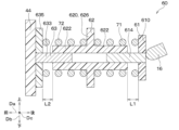
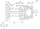
- FIG. 1 is a configuration diagram of a brake-by-wire system in which the pedal device of the first embodiment is used.
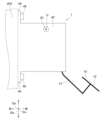
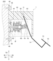
- a side view of the pedal device. A cross-sectional view of the pedal device.
- FIG. 4 is an enlarged view of part IV in FIG. 3. Part of a cross-sectional view taken along the line V-V in FIG. 4.
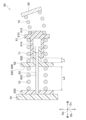
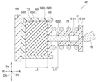
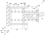
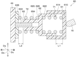
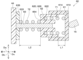
- FIG. 3 is a sectional view of a reaction force generation mechanism of a pedal device according to a second embodiment.
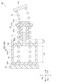
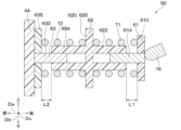
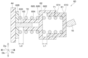
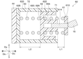
- FIG. 7 is a sectional view of a reaction force generation mechanism of a pedal device according to a third embodiment.
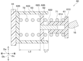
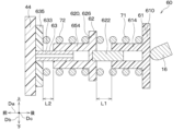
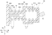
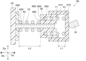
- FIG. 4 is a sectional view of a reaction force generation mechanism of a pedal device according to a fourth embodiment.
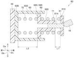
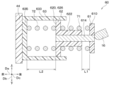
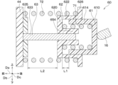
- FIG. 7 is a sectional view of a reaction force generating mechanism of a pedal device according to a fifth embodiment.
- FIG. 7 is a sectional view of a reaction force generation mechanism of a pedal device according to a sixth embodiment.
- FIG. 7 is a sectional view of a reaction force generation mechanism of a pedal device according to a seventh embodiment.
- FIG. 7 is a sectional view of a reaction force generation mechanism of a pedal device according to an eighth embodiment.
- FIG. 9 is a sectional view of a reaction force generation mechanism of a pedal device according to a ninth embodiment.
- FIG. 7 is a sectional view of a reaction force generation mechanism of a pedal device according to a tenth embodiment.
- FIG. 7 is a sectional view of a reaction force generation mechanism of a pedal device according to an eleventh embodiment.
- FIG. 7 is a sectional view of a reaction force generating mechanism of a pedal device according to a twelfth embodiment.
- FIG. 7 is a sectional view of a reaction force generation mechanism of a pedal device according to a thirteenth embodiment.
- FIG. 7 is a sectional view of a reaction force generation mechanism of a pedal device according to a fourteenth embodiment.
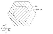
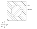
- FIG. 7 is a sectional view of a first guide part and a second guide part of a pedal device according to a fifteenth embodiment.
- FIG. 3 is a sectional view of a second support portion and a third guide portion of the pedal device.
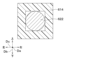
- FIG. 7 is a sectional view of a first guide part and a second guide part of a pedal device according to a sixteenth embodiment.
- FIG. 3 is a sectional view of a second support portion and a third guide portion of the pedal device.
- FIG. 7 is a sectional view of a reaction force generation mechanism of a pedal device according to a seventeenth embodiment.
- FIG. 7 is a sectional view of a reaction force generation mechanism of a pedal device according to an eighteenth embodiment.
- FIG. 9 is a sectional view of a reaction force generation mechanism of a pedal device according to a nineteenth embodiment.
- FIG. 7 is a sectional view of a reaction force generation mechanism of a pedal device according to a twentieth embodiment.
- FIG. 7 is a sectional view of a reaction force generation mechanism of a pedal device according to a twenty-first embodiment.
- FIG. 7 is a sectional view of a reaction force generation mechanism of a pedal device according to a twenty-second embodiment.
- FIG. 7 is a sectional view of a reaction force generation mechanism of a pedal device according to a twenty-third embodiment.
- FIG. 7 is a sectional view of a reaction force generation mechanism of a pedal device according to a twenty-fourth embodiment.
- FIG. 7 is a sectional view of a reaction force generation mechanism of a pedal device according to a twenty-fifth embodiment.
- FIG. 7 is a sectional view of a reaction force generation mechanism of a pedal device according to a twenty-fifth embodiment.
- FIG. 7 is a sectional view of a reaction force generation mechanism of a pedal device according to a twenty-sixth embodiment.
- FIG. 7 is a sectional view of a reaction force generation mechanism of a pedal device according to a twenty-seventh embodiment.
- FIG. 7 is a sectional view of a reaction force generating mechanism of a pedal device according to a twenty-eighth embodiment.
- FIG. 7 is a sectional view of a reaction force generating mechanism of a pedal device according to a twenty-ninth embodiment.
- FIG. 7 is a sectional view of a reaction force generation mechanism of a pedal device according to a 30th embodiment.
- FIG. 7 is a cross-sectional view of a reaction force generation mechanism of a pedal device according to a thirty-first embodiment.
- FIG. 7 is a sectional view of a reaction force generation mechanism of a pedal device according to a thirty-second embodiment.
- FIG. 7 is a sectional view of a reaction force generation mechanism of a pedal device according to a thirty-third embodiment.
- FIG. 7 is a sectional view of a reaction force generation mechanism of a pedal device according to a thirty-fourth embodiment.
- FIG. 7 is a sectional view of a reaction force generation mechanism of a pedal device according to a thirty-fifth embodiment.
- FIG. 7 is a sectional view of a reaction force generation mechanism of a pedal device according to a thirty-sixth embodiment.
- FIG. 7 is a sectional view of a reaction force generation mechanism of a pedal device according to a thirty-seventh embodiment.
- FIG. 7 is a sectional view of a reaction force generation mechanism of a pedal device according to a thirty-seventh embodiment.
- FIG. 7 is a sectional view of a reaction force generation mechanism of a pedal device according to a thirty-eighth embodiment.
- FIG. 7 is a sectional view of a reaction force generation mechanism of a pedal device according to a thirty-ninth embodiment.
- FIG. 7 is a sectional view of a reaction force generation mechanism of a pedal device according to a fortieth embodiment.
- the pedal device 1 of this embodiment is used, for example, as a brake pedal in a brake-by-wire system 150 that controls the brakes of a vehicle. First, this brake-by-wire system 150 will be explained.
- the brake-by-wire system 150 includes wheel cylinders 131 to 134, an ECU 110, a brake circuit 120, and a pedal device 1.
- the wheel cylinders 131 to 134 are arranged at each wheel of the vehicle. Furthermore, brake pads (not shown) are attached to each of the wheel cylinders 131 to 134.
- the ECU 110 includes a first ECU 111 and a second ECU 112.
- the first ECU 111 includes a microcomputer, a drive circuit, etc. (not shown). Further, the first ECU 111 controls a first brake circuit 121 of a brake circuit 120, which will be described later, based on a signal from the pedal device 1, which will be described later.
- the second ECU 112 includes a microcomputer, a drive circuit, etc. (not shown). Further, the second ECU 112 controls a second brake circuit 122 of a brake circuit 120, which will be described later, based on a signal from the pedal device 1, which will be described later.
- the brake circuit 120 has a first brake circuit 121 and a second brake circuit 122.
- the first brake circuit 121 includes a reservoir 124, a motor 123, a gear mechanism 125, and a master cylinder 126. Reservoir 124 stores brake fluid. Motor 123 drives gear mechanism 125. The gear mechanism 125 reciprocates a master piston 127 included in the master cylinder 126 in the axial direction of the master cylinder 126.
- the second brake circuit 122 includes a solenoid valve (not shown) and the like. Further, the second brake circuit 122 controls the hydraulic pressure of each wheel cylinder 131 to 134 by opening and closing a solenoid valve in response to a control signal from the second ECU 112.
- the longitudinal direction of the vehicle will be referred to as the vehicle longitudinal direction Da.
- the vertical direction of the vehicle is defined as the vehicle vertical direction Db.
- the left-right direction of the vehicle is defined as vehicle left-right direction Dc.
- the front in the vehicle longitudinal direction Da is described as the vehicle front.
- the rear in the vehicle longitudinal direction Da is referred to as the vehicle rear.
- the upper part in the vehicle vertical direction Db is referred to as the upper part of the vehicle.
- the downward direction in the vehicle vertical direction Db is referred to as the vehicle downward direction.
- the left side in the vehicle left-right direction Dc is referred to as the vehicle left side.
- the right side in the vehicle left-right direction Dc is referred to as the right side of the vehicle.
- the pedal device 1 includes a pedal 10, a stroke sensor 30, a housing 40, and a reaction force generating mechanism 60.
- the pedal 10 is operated by being stepped on by the driver of the vehicle, as shown in FIGS. 2 and 3. Note that the driver of the vehicle corresponds to the operator.
- the pedal 10 has a pedal portion 12, a lever portion 14, a lever protrusion 16, and a lever flange portion 18.
- the pedal section 12 is stepped on by the driver.
- the lever section 14 is connected to the pedal section 12. Further, the lever section 14 rotates around the rotation axis O when the pedal section 12 is stepped on by the driver.
- the lever convex portion 16 is connected to the vehicle front side of the lever portion 14 and protrudes from the boundary with the lever portion 14 in the vehicle front direction.
- the lever flange 18 is connected to the lever protrusion 16 and protrudes from the boundary with the lever protrusion 16 in a direction perpendicular to the direction in which the lever protrusion 16 projects.
- the stroke sensor 30 is arranged, for example, on the rotation axis O of the lever part 14. Further, the stroke sensor 30 includes a magnet, a yoke, a Hall element, and the like. Thereby, the stroke sensor 30 detects the rotation angle and stroke amount of the pedal 10 by detecting the rotation angle of the lever portion 14. Further, the stroke sensor 30 outputs signals corresponding to the detected rotation angle and stroke amount of the pedal 10 to the first ECU 111 and the second ECU 112. Note that the stroke sensor 30 has a Hall element to detect the rotation angle and stroke amount of the pedal 10, but is not limited to this, and has an MR element etc. to detect the rotation angle and stroke amount of the pedal 10. May be detected. MR is an abbreviation for Magneto Resistive. Further, the stroke amount is, for example, the amount of movement of the pedal portion 12 in the vehicle longitudinal direction Da.
- the housing 40 is attached to the dash panel 200 of the vehicle, and is formed into a cylindrical shape with a bottom so that it accommodates a portion of the lever portion 14, the stroke sensor 30, and a reaction force generating mechanism 60, which will be described later.
- the dash panel 200 is a partition wall that separates the outside of the vehicle, such as the engine room, from the interior of the vehicle, and is sometimes called a bulkhead. Further, outside the vehicle interior, not only the vehicle engine but also the vehicle battery, air conditioner, etc. are arranged.
- the housing 40 includes a housing bottom portion 42, a housing cylinder portion 44, a panel attachment portion 46, a panel bolt 48, and a housing restriction portion 50.
- the housing bottom portion 42 extends in the vehicle longitudinal direction Da. Furthermore, the rotation axis O of the lever portion 14 and the stroke sensor 30 are attached to the housing bottom portion 42 . Furthermore, the housing bottom part 42 supports a part of the lever part 14 so that the lever part 14 can rotate about the rotation axis O, and also supports the stroke sensor 30.
- the housing cylinder portion 44 corresponds to the fourth support portion, is connected to the end of the housing bottom portion 42 in the vehicle longitudinal direction Da, and extends downward from the boundary with the housing bottom portion 42. Further, the housing cylindrical portion 44 accommodates a portion of the lever portion 14, a stroke sensor 30, and a reaction force generating mechanism 60, which will be described later.
- the panel mounting portion 46 is connected to the end of the housing bottom portion 42 on the vehicle front side and the vehicle upper side, and extends from the boundary with the housing bottom portion 42 in the vehicle upward direction. Further, the panel mounting portion 46 is connected to the end of the housing cylindrical portion 44 on the vehicle front side and the vehicle lower side, and extends from the boundary with the housing cylindrical portion 44 in the vehicle downward direction. A hole is formed in the panel attachment part 46, and the panel bolt 48 is inserted into the hole of the panel attachment part 46 and the hole of the dash panel 200, so that the housing 40 is attached to the dash panel 200. installed.
- the housing regulating portion 50 is connected to the inner surface of the housing cylindrical portion 44 located on the front side of the vehicle, and protrudes from the inner surface toward the rear of the vehicle. Further, the housing regulating portion 50 is formed with a hole into which a guide member 63, which will be described later, is inserted.
- the reaction force generation mechanism 60 generates a reaction force against the driver's pedal force applied to the pedal section 12.
- the reaction force generation mechanism 60 includes a first holder 61, a second holder 62, a guide member 63, a first elastic member 71, a second elastic member 72, and a third elastic member 73. has.
- the first holder 61 is made of resin, for example. Further, the first holder 61 includes a first support section 610, a holder restriction section 612, and a first guide section 614. Although the first holder 61 is made of resin, it is not limited thereto, and may be made of metal, for example.
- the first support portion 610 is, for example, formed in a plate shape extending in a direction perpendicular to the vehicle longitudinal direction Da.
- the holder regulating portion 612 is connected to the first support portion 610 and protrudes from the first support portion 610 in the vehicle rear direction.
- the first guide portion 614 is formed in a cylindrical shape that extends toward the front of the vehicle from the side of the first support portion 610 opposite to the holder restriction portion 612.
- the second holder 62 is made of resin, for example. Further, the second holder 62 includes a second support section 620, a second guide section 622, a holder cylinder section 624, and a third support section 626. Although the second holder 62 is made of resin, it is not limited thereto, and may be made of metal, for example.
- the second support portion 620 is formed in a plate shape extending in a direction perpendicular to the vehicle longitudinal direction Da, and is also formed in an annular shape.
- the second guide portion 622 is connected to the inside of the second support portion 620 in a direction perpendicular to the vehicle longitudinal direction Da, and has a cylindrical shape extending from the boundary with the second support portion 620 toward the rear of the vehicle. It is formed. Further, a part of the second guide section 622 is inserted into the hole of the first guide section 614. Thereby, movement of the first guide part 614 and the second guide part 622 in the vehicle vertical direction Db is mutually restricted. Furthermore, since the first guide part 614 and the second guide part 622 extend in the vehicle longitudinal direction Da, the inner surface of the first guide part 614 and the outer surface of the second guide part 622 are connected to each other along the vehicle longitudinal direction Da. Sliding.
- the holder cylinder portion 624 is connected to the outside of the second support portion 620 in a direction orthogonal to the vehicle longitudinal direction Da, and extends from the boundary with the second support portion 620 in the vehicle rear direction.
- the third support portion 626 is formed in a plate shape extending in a direction perpendicular to the vehicle longitudinal direction Da, and is also formed in an annular shape. Furthermore, the third support portion 626 is connected to the side of the holder cylinder portion 624 opposite to the second support portion 620, and is therefore disposed on the vehicle rear side relative to the second support portion 620. Furthermore, a part of the first guide part 614 is inserted into the hole of the third support part 626.
- the guide member 63 includes a third guide portion 633.
- the third guide portion 633 is made of metal, for example. Further, the third guide portion 633 is formed in a cylindrical shape extending in the vehicle longitudinal direction Da. Further, a portion of the third guide portion 633 is inserted into the hole of the housing cylinder portion 44 and the housing restriction portion 50. Further, a part of the third guide part 633 is inserted into the hole of the second guide part 622. Thereby, movement of the second guide part 622 and the third guide part 633 in the vehicle vertical direction Db is mutually restricted. Furthermore, since the second guide portion 622 and the third guide portion 633 extend in the vehicle longitudinal direction Da, the inner surface of the second guide portion 622 and the outer surface of the third guide portion 633 are mutually connected along the vehicle longitudinal direction Da. Sliding.
- the distance between the first holder 61 and the second holder 62 in the vehicle longitudinal direction Da is such that the first holder 61 and the second holder 62 come into contact after the pedal 10 is stepped on by the driver of the vehicle.
- the moving distance of the first holder 61 up to this point is defined as a first distance L1.
- the first distance L1 is the distance from the first guide portion 614 to the second support portion 620 in the vehicle longitudinal direction Da.
- the moving distance of the second holder 62 until it comes into contact with the opposing portion is defined as a second distance L2.
- the second distance L2 is the distance from the second holder 62 to the housing regulating portion 50 in the vehicle longitudinal direction Da.
- the first elastic member 71, the second elastic member 72, and the third elastic member 73 are arranged in series here.
- the first elastic member 71 is, for example, a coil spring, and is elastically deformed in the vehicle longitudinal direction Da. Further, inside the first elastic member 71, a first guide section 614 and a second guide section 622 are arranged. This restricts the movement of the first elastic member 71 in the vehicle vertical direction Db. Furthermore, the first elastic member 71 is supported by the first support part 610 and the second support part 620 by being in contact with the first support part 610 and the second support part 620. Further, when the pedal portion 12 is not depressed by the driver, the first elastic member 71 is elastically deformed, and is compressed here.
- the first elastic member 71 when the pedal portion 12 is not depressed by the driver, the first elastic member 71 is elastically deformed, but the present invention is not limited to this, and the first elastic member 71 may not be elastically deformed. In this case, the length of the first elastic member 71 is a free length.
- the second elastic member 72 is, for example, a coil spring, and is elastically deformed in the vehicle longitudinal direction Da. Further, the second elastic member 72 is supported by the second support part 620 and the housing cylinder part 44 by being in contact with the third support part 626 and the housing cylinder part 44 . Further, inside the second elastic member 72, the housing regulating portion 50 and the holder cylinder portion 624 are arranged. This restricts movement of the second elastic member 72 in the vehicle vertical direction Db. Further, when the second elastic member 72 is projected toward the first elastic member 71 in the vehicle vertical direction Db, the projected second elastic member 72 and the first elastic member 71 overlap. Further, when the pedal portion 12 is not depressed by the driver, the second elastic member 72 is elastically deformed, and is compressed here.
- the second elastic member 72 when the pedal portion 12 is not depressed by the driver, the second elastic member 72 is elastically deformed, but the second elastic member 72 is not limited to this, and may not be elastically deformed. In this case, the length of the second elastic member 72 is a free length.
- the third elastic member 73 is, for example, a coil spring, and is elastically deformed in the vehicle longitudinal direction Da. Furthermore, the third elastic member 73 is supported by the first support section 610 by being in contact with the first support section 610 . Further, a holder regulating portion 612 is arranged inside the third elastic member 73. This restricts movement of the third elastic member 73 in the vehicle vertical direction Db. Further, when the pedal portion 12 is not depressed by the driver, a portion of the lever convex portion 16 is inserted inside the third elastic member 73, so that the third elastic member 73 is in contact with. At this time, the third elastic member 73 is elastically deformed and is compressed here.
- the third elastic member 73 when the pedal portion 12 is not depressed by the driver, the third elastic member 73 is elastically deformed, but the present invention is not limited to this, and the third elastic member 73 may not be elastically deformed. In this case, the length of the third elastic member 73 is a free length. Further, the third elastic member 73 and the lever flange 18 are in contact with each other when the pedal portion 12 is not depressed by the driver, but the present invention is not limited to this. When the pedal portion 12 is not stepped on by the driver, the third elastic member 73 and the lever flange 18 may be out of contact because the third elastic member 73 and the lever flange 18 are separated from each other. .
- the brake-by-wire system 150 is configured as described above. Next, the operation of the pedal device 1 will be explained.
- the lever part 14 rotates around the rotation axis O together with the pedal part 12.
- the force from the pedal portion 12 is transmitted to the third elastic member 73 via the lever flange portion 18, so that the third elastic member 73 is compressed.
- the force from the pedal section 12 is transmitted to the first holder 61. Therefore, since the first holder 61 moves in the vehicle front direction, the inner surface of the first guide part 614 slides along the outer surface of the second guide part 622 in the vehicle front direction, and the first elastic member 71 It is compressed by being pushed by the first support part 610 . Further, the force from the pedal section 12 is transmitted to the second holder 62.
- the second holder 62 moves in the vehicle front direction, so the inner surface of the second guide section 622 slides along the outer surface of the third guide section 633 in the vehicle front direction, and the second elastic member 72 It is compressed by being pushed by the third support portion 626 . Therefore, a reaction force is generated by the restoring force generated when the first elastic member 71, the second elastic member 72, and the third elastic member 73 are compressed. Due to this reaction force, even if the mechanical connection between the pedal 10 and the master cylinder 126 is abolished, the pedal device 1 generates the same reaction as when the pedal is connected to the master cylinder 126, that is, when the reaction force by hydraulic pressure is obtained. You can gain power.
- the stroke sensor 30 detects the rotation angle and stroke amount of the pedal section 12 by detecting the rotation angle of the lever section 14. Further, the stroke sensor 30 outputs the detected rotation angle and stroke amount of the pedal section 12 to the first ECU 111 and the second ECU 112.
- the first ECU 111 rotates the motor 123 by, for example, supplying electric power to the motor 123.
- the gear mechanism 125 is driven, and the master piston 127 moves. Therefore, the hydraulic pressure of the brake fluid supplied from the reservoir 124 to the master cylinder 126 increases. This increased hydraulic pressure is supplied to the second brake circuit 122.
- the second ECU 112 supplies power to a solenoid valve (not shown) of the second brake circuit 122, for example. This opens the solenoid valve of the second brake circuit 122. Therefore, the brake fluid supplied to the second brake circuit 122 is supplied to each wheel cylinder 131-134. Therefore, the brake pads attached to the wheel cylinders 131-134 rub against their corresponding brake discs. Therefore, each wheel is braked, so the vehicle decelerates.
- the second ECU 112 may perform ABS control, VSC control, collision avoidance control, regeneration coordination control, etc. based on the signal from the stroke sensor 30 and the signal from another electronic control device (not shown). Note that ABS is an abbreviation for Anti-lock Braking System. Furthermore, VSC is an abbreviation for Vehicle Stability Control.
- the absolute value of the deceleration amount of the vehicle is equal to or greater than the first threshold value.
- the vehicle will stop.
- the first guide part 614 and the second guide part 622 are fixed, when the second holder 62 moves the second distance L2, the absolute value of the deceleration amount of the vehicle becomes equal to or greater than the second threshold value, The vehicle stops.
- the first threshold value and the second threshold value are set through experiments, simulations, etc. so that a sufficient amount of deceleration of the vehicle can be obtained.
- the first holder 61 and the second holder 62 are pushed back toward the rear of the vehicle by the restoring forces of the first elastic member 71 and the second elastic member 72.
- the inner surface of the first guide section 614 slides along the outer surface of the second guide section 622 in the rear direction of the vehicle, and the inner surface of the second guide section 622 slides on the outer surface of the third guide section 633 in the rear direction of the vehicle. slide along.
- the lever flange 18 is pushed back by the restoring force of the third elastic member 73. Therefore, the position of the pedal 10 returns to the initial position when the pedal portion 12 is not depressed by the driver of the vehicle.
- the pedal device 1 operates. This pedal device 1 prevents the pedal 10 from becoming unable to rotate when the pedal 10 is stepped on. Next, a description will be given of how to prevent the pedal 10 from being unable to rotate.
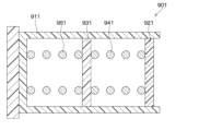
- the first pedal device 901 for comparison includes a first guide section 911 for comparison, a first support section 921 for comparison, a second support section 931 for comparison, a first elastic member 941 for comparison, and a first elastic member 941 for comparison.
- a second elastic member 951 and a comparative pedal are provided.
- the first guide section 911 for comparison is formed in a cylindrical shape with a bottom, so that the first guide section 911 for comparison is formed in a cylindrical shape with a bottom, so that it can accommodate a first support section 921 for comparison, a second support section 931 for comparison, a first elastic member 941 for comparison, and a first elastic member 941 for comparison, which will be described later.
- 2 elastic members 951 are housed therein.
- the first support part 921 for comparison and the second support part 931 for comparison are formed in a plate shape extending in a direction perpendicular to the left-right direction in the drawing.
- the side surfaces of the first comparison support section 921 and the second comparison support section 931 that extend in the left-right direction in the drawing slide against the inner surface of the first comparison guide section 911 in the left-right direction in the drawing.
- the second support part 931 for comparison is disposed on the left side of the paper plane compared to the first support part 921 for comparison.
- the first elastic member 941 for comparison is disposed between the first support part 921 for comparison and the second support part 931 for comparison, and is supported by the first support part 921 for comparison and the second support part 931 for comparison. has been done.
- the second elastic member 951 for comparison is disposed between the bottoms of the second support part 931 for comparison and the first guide part 911 for comparison, and is located between the second support part 931 for comparison and the first guide part 911 for comparison. is supported at the bottom of the Further, the first comparative elastic member 941 and the second comparative elastic member 951 are elastically deformed in the left-right direction in the drawing.
- the first comparative pedal device 901 for example, minute objects or foreign objects entering from the outside enter between the first comparative support part 921 and the first comparative guide part 911 at the sliding portion.
- the first comparison support part 921 and the first comparison guide part 911 are fixed, and the first comparison support part 921 cannot move along the comparison first guide part 911.
- the first elastic member 941 for comparison cannot be elastically deformed, so that the force of the pedal for comparison (not shown) is no longer transmitted to the second support part 931 for comparison. Therefore, the second comparison support section 931 also becomes unable to move along the comparison first guide section 911.
- the comparative pedal (not shown) cannot be rotated.
- the reaction force by the first comparison elastic member 941 and the second comparison elastic member 951 is no longer transmitted to the comparison pedal (not shown).
- the fine particles are, for example, abrasion particles generated by sliding between the first comparative support part 921, the second comparative support part 931, and the first comparative guide part 911.
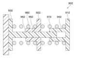
- the second pedal device 902 for comparison includes a third support section 912 for comparison, a fourth support section 922 for comparison, and a fifth support section 932 for comparison. Further, the second pedal device 902 for comparison includes a first cylindrical portion 942 for comparison, a second cylindrical portion 952 for comparison, a second guide portion 962 for comparison, a third elastic member 972 for comparison, and a fourth elastic member 982 for comparison. and a comparison pedal (not shown).
- the third comparison support part 912, the fourth comparison support part 922, and the fifth comparison support part 932 are formed in a plate shape extending in a direction perpendicular to the left-right direction in the drawing.
- the fourth support part 922 for comparison is arranged on the left side of the paper surface compared to the third support part 912 for comparison.
- the fifth support part 932 for comparison is arranged on the left side of the plane of the drawing compared to the fourth support part 922 for comparison.
- the first cylindrical portion 942 for comparison is connected to the third support portion 912 for comparison, and extends from the boundary with the third support portion 912 for comparison to the left in the drawing.
- the second cylindrical portion 952 for comparison is connected to the fourth support portion 922 for comparison, and extends from the boundary with the fourth support portion 922 for comparison to the left in the drawing.
- the second guide part 962 for comparison is connected to the fifth support part 932 for comparison, and is formed in a columnar shape extending from the fifth support part 932 for comparison in the right direction in the drawing.
- a part of the second guide section 962 for comparison is inserted into the hole of the first cylindrical section 942 for comparison and the hole of the second cylindrical section 952 for comparison.
- the third elastic member 972 for comparison is disposed between the third support part 912 for comparison and the fourth support part 922 for comparison, and is supported by the third support part 912 for comparison and the fourth support part 922 for comparison. has been done.
- the fourth elastic member 982 for comparison is disposed between the fourth support section 922 for comparison and the fifth support section 932 for comparison, and is supported by the fourth support section 922 for comparison and the fifth support section 932 for comparison. has been done. Furthermore, the third comparative elastic member 972 and the fourth comparative elastic member 982 are elastically deformed in the left-right direction in the drawing.
- the second comparative pedal device 902 for example, minute objects or foreign objects entering from the outside enter between the first comparative cylindrical portion 942 and the second comparative guide portion 962 at the sliding portion.
- the first comparison cylinder part 942 and the second comparison guide part 962 are fixed, and the first comparison cylinder part 942 cannot move along the comparison second guide part 962.
- the third elastic member 972 for comparison cannot be elastically deformed, so that the force of the comparison pedal (not shown) is no longer transmitted to the fourth support part 922 for comparison and the second cylindrical part 952 for comparison.
- the second comparative cylindrical part 952 also becomes unable to move along the comparative second guide part 962.
- the comparative pedal (not shown) cannot be rotated.
- the reaction force by the third comparison elastic member 972 and the fourth comparison elastic member 982 is no longer transmitted to the comparison pedal (not shown).
- the fine particles are, for example, abrasion powder generated by sliding between the first comparative cylindrical part 942, the second comparative cylindrical part 952, and the second comparative guide part 962.
- the first guide section 614 slides along the vehicle longitudinal direction Da with the second guide section 622 due to the force from the pedal 10 when the pedal 10 rotates.
- the first elastic member 71 is deformed.
- the second guide part 622 of the second holder 62 slides with the third guide part 633 along the vehicle longitudinal direction Da, so that the second elastic member 72 is deformed.
- the vehicle longitudinal direction Da corresponds to the deformation direction of the first elastic member 71 and the deformation direction of the second elastic member 72.
- the force from the pedal 10 when the pedal 10 rotates causes the first guide part 614 and the second guide part 622 to move forward and backward of the vehicle. It slides along the direction Da.
- the force from the pedal 10 when the pedal 10 rotates causes the second guide part 622 and the third guide part of the second holder 62 to 633 slides along the vehicle longitudinal direction Da. Therefore, even if one of the two sliding parts is fixed, the other sliding part will slide. This prevents the pedal 10 from becoming unable to rotate when the pedal 10 is depressed.
- the first embodiment also provides the effects described below.
- the first guide portion 614 is formed in a cylindrical shape.
- the second guide portion 622 is formed in a cylindrical shape.
- the third guide portion 633 is formed in a cylindrical shape. Therefore, when the second guide part 622 and the third guide part 633 are assembled, even if the second guide part 622 and the third guide part 633 rotate around the axis, the shapes of the second guide part 622 and the third guide part 633 can easily correspond to each other. For this reason, when assembling the second guide part 622 and the third guide part 633, it is possible to assemble the second guide part 622 and the third guide part 633 without considering the rotation direction of the second guide part 622 and the third guide part 633 around their axes. Therefore, the second guide part 622 and the third guide part 633 can be easily assembled.
- the deformation direction of the first elastic member 71, the deformation direction of the second elastic member 72, and the deformation direction of the third elastic member 73 are in a linear direction perpendicular to the rotation axis O, here, in the vehicle longitudinal direction Da. be.
- the first elastic member 71, the second elastic member 72, and the third elastic member 73 are easily compressed without being tilted, so that a stable reaction force is generated.
- the size of the reaction force generating mechanism 60 in the vehicle longitudinal direction Da becomes smaller compared to the case where the second elastic member 72 and the first elastic member 71 projected in the vehicle vertical direction Db do not overlap. Therefore, the increase in the size of the pedal device 1 is suppressed.
- a space is formed inside the first elastic member 71, and the first guide section 614 and the second guide section 622 are arranged inside the first elastic member 71.
- the physique of the first holder 61 and the second holder 62 in the vehicle vertical direction Db is reduced. becomes smaller. Therefore, the increase in the size of the pedal device 1 is suppressed.
- the first guide part 614 and the second guide part 622 are surrounded by the first elastic member 71, foreign objects from the outside are less likely to enter the sliding parts of the first guide part 614 and the second guide part 622.
- a space is formed inside the second elastic member 72, and the second guide section 622 and the third guide section 633 are arranged inside the second elastic member 72. Therefore, the size of the second holder 62 in the vehicle vertical direction Db becomes smaller compared to the case where the second guide part 622 and the third guide part 633 are arranged outside the second elastic member 72. Therefore, the increase in the size of the pedal device 1 is suppressed. Furthermore, since the second guide section 622 and the third guide section 633 are surrounded by the second elastic member 72, foreign objects from the outside are less likely to enter the sliding portions of the second guide section 622 and the third guide section 633.
- the first guide portion 614 and the second guide portion 622 restrict movement of the first elastic member 71 in the vehicle vertical direction Db.
- the first elastic member 71 becomes difficult to move in the vehicle vertical direction Db, and therefore friction with the first support part 610 and the second support part 620 that support the first elastic member 71 becomes difficult to occur. Therefore, the amount of wear on the first elastic member 71, the first support section 610, and the second support section 620 is reduced.
- the first elastic member 71 becomes difficult to move in the vehicle vertical direction Db, the first elastic member 71 is easily compressed without being tilted, so that a stable reaction force is generated.
- the first guide section 614 and the second guide section 622 correspond to a restriction section.
- the holder cylinder portion 624 and the housing restriction portion 50 restrict movement of the second elastic member 72 in the vehicle vertical direction Db.
- the second elastic member 72 becomes difficult to move in the vehicle vertical direction Db, and therefore friction with the third support portion 626 that supports the second elastic member 72 and the housing cylinder portion 44 is less likely to occur. Therefore, the amount of wear on the second elastic member 72, the third support section 626, and the housing cylinder section 44 is reduced.
- the second elastic member 72 becomes difficult to move in the vehicle vertical direction Db, the second elastic member 72 is easily compressed without being tilted, so that a stable reaction force is generated.
- the holder cylinder portion 624 and the housing restriction portion 50 correspond to the restriction portion.
- the third guide portion 633 includes metal. Thereby, since metal is a material that is relatively hard to deform, it is possible to prevent the third guide part 633 from being damaged and not sliding on the second guide part 622. Further, the housing 40 includes resin. Therefore, when forming the housing 40 connected to the third guide portion 633, it is possible to perform integral molding by, for example, injection molding. Furthermore, the second guide portion 622 includes resin. As a result, the coefficient of friction between the second guide section 622 and the third guide section 633 becomes smaller than when the second guide section 622 and the third guide section 633 are made of metal.
- the frictional force between the second guide section 622 and the third guide section 633 is reduced, the generation of noise due to the friction between the second guide section 622 and the third guide section 633 is suppressed. Furthermore, since resin has a relatively low specific gravity, the weight of the second guide section 622 is suppressed, thereby making it possible to make the second guide section 622 lightweight. Therefore, the weight of the pedal device 1 is suppressed, so that the pedal device 1 can be made lightweight.
- the first elastic member 71, the second elastic member 72, and the third elastic member 73 are coil springs. Thereby, the influence of temperature on the elastic coefficients of the first elastic member 71, the second elastic member 72, and the third elastic member 73 is relatively small. Further, the first elastic member 71, the second elastic member 72, and the third elastic member 73 have relatively high oil resistance, solvent resistance, and chemical resistance. For this reason, the first elastic member 71, the second elastic member 72, and the third elastic member 73 are relatively unlikely to deteriorate, so that a stable reaction force is generated.
- the pedal 10 is a brake pedal used in a vehicle.
- the pedal device 1 of this embodiment since it is suppressed that the pedal 10 cannot be rotated when the pedal 10 is depressed, it is suppressed that the vehicle cannot be braked.
- the first guide portion 614 faces the second support portion 620 in the vehicle longitudinal direction Da, and is moved toward the second support portion 620 by the force from the pedal 10 when the pedal 10 rotates. and move.
- the second support part 620 and the third support part 626 face the housing cylinder part 44 in the vehicle longitudinal direction Da, and are directed toward the housing cylinder part 44 by the force from the pedal 10 when the pedal 10 rotates.
- the first holder 61 moves the first distance L1
- the absolute value of the deceleration amount of the vehicle becomes equal to or greater than the threshold value
- the vehicle stops stops.
- the second holder 62 moves the second distance L2
- the absolute value of the deceleration amount of the vehicle becomes equal to or greater than the threshold value, and the vehicle stops.
- the housing 40 that accommodates the reaction force generating mechanism 60 is arranged on the interior side of the dash panel 200 that separates the outside of the vehicle from the interior of the vehicle.
- the first elastic member 71, second elastic member 72, and third elastic member of the reaction force generation mechanism 60 Difficult to adhere to 73.
- external factors such as light and heat from the engine compartment are difficult to enter into the vehicle interior. Therefore, the first elastic member 71, the second elastic member 72, and the third elastic member 73 are less likely to deteriorate, so that durability is improved.
- the first guide portion 614 and the second guide portion 622 mutually restrict movement of the vehicle in the vertical direction Db.
- the vehicle vertical direction Db corresponds to a direction perpendicular to the deformation direction of the first elastic member 71.
- the second holder 62 and the third guide portion 633 mutually restrict movement in the vehicle vertical direction Db.
- the vehicle vertical direction Db corresponds to a direction perpendicular to the deformation direction of the second elastic member 72.
- the first elastic member 71, the second elastic member 72, and the third elastic member 73 are elastically deformed when the pedal 10 is not depressed by the driver of the vehicle, and here, they are compressed. There is. As a result, even if the first elastic member 71, second elastic member 72, and third elastic member 73 are damaged while being elastically deformed when the pedal 10 is stepped on by the driver of the vehicle, they return to their respective free lengths. The restoring force generated by this makes it easier for the pedal 10 to return to its original position.
- the shape of the pedal 10 is different from the first embodiment.
- the form of the second holder 62 is different from the first embodiment.
- the form of the guide member 63 is different from the first embodiment.
- the housing 40 does not have the housing regulating part 50.
- the second embodiment is the same as the first embodiment.
- the pedal 10 has a lever plate portion 20 instead of the lever convex portion 16 and the lever collar portion 18.
- the lever plate portion 20 is formed in a plate shape and is connected to the vehicle front side of the lever portion 14. Further, the lever plate portion 20 is in contact with a side of the third elastic member 73 opposite to the first support portion 610 . At this time, the third elastic member 73 is not elastically deformed. Therefore, when the pedal portion 12 is not depressed by the driver, the third elastic member 73 has a free length.
- the third elastic member 73 is not elastically deformed, but the third elastic member 73 is not limited to this, and may be elastically deformed.
- the third elastic member 73 and the lever plate part 20 are in contact with each other when the pedal part 12 is not depressed by the driver, but the present invention is not limited to this.
- the third elastic member 73 and the lever plate part 20 may be out of contact with each other because the third elastic member 73 and the lever plate part 20 are separated. .
- the second holder 62 does not include the holder cylinder portion 624. Moreover, the second support part 620 and the third support part 626 of the second holder 62 are integrated.
- the guide member 63 has a guide member bottom portion 635.
- the guide member bottom portion 635 corresponds to the fourth support portion.
- the guide member bottom portion 635 is made of resin, for example.
- the guide member bottom portion 635 is connected to the third guide portion 633.
- the guide member bottom portion 635 is connected to the inner surface of the housing cylindrical portion 44 located on the front side of the vehicle.
- the guide member bottom portion 635 supports the second elastic member 72 by contacting the side of the second elastic member 72 opposite to the third support portion 626 .
- the pedal device 1 of the second embodiment is configured.
- This second embodiment also provides the same effects as the first embodiment.
- the second holder 62 has a second support part 620, a third support part 626, and a second guide part 622.
- the second support portion 620 is integrally formed with the third support portion 626 in a plate shape extending in the vehicle vertical direction Db.
- the second guide portion 622 is made of metal, for example. Further, the second guide portion 622 is connected to the second support portion 620 and is formed in a cylindrical shape extending from the boundary with the second support portion 620 toward the rear of the vehicle. Further, a part of the second guide section 622 is inserted into the hole of the first guide section 614. As a result, movements of the first guide section 614 and the second guide section 622 in the vehicle vertical direction Db are mutually restricted. Furthermore, since the first guide part 614 and the second guide part 622 extend in the vehicle longitudinal direction Da, the inner surface of the first guide part 614 and the outer surface of the second guide part 622 are connected to each other along the vehicle longitudinal direction Da. Sliding.
- the third guide portion 633 is made of resin instead of metal. Further, the third guide portion 633 is formed in a cylindrical shape extending in the vehicle longitudinal direction Da, instead of having a cylindrical shape. As a result, the guide member 63 is formed into a cylindrical shape with a bottom. Further, the second support section 620 and the third support section 626 are inserted into the hole of the third guide section 633. This restricts movement of the second support portion 620, the third support portion 626, and the third guide portion 633 in the vehicle vertical direction Db. Further, since the third guide portion 633 extends in the vehicle longitudinal direction Da, the side surfaces of the second support portion 620 and the third support portion 626 extending in the vehicle longitudinal direction Da and the third guide The inner surface of the portion 633 slides.
- the pedal device 1 of the third embodiment is configured.
- This third embodiment also provides the same effects as the second embodiment.
- the shape of the pedal 10 is different from that in the third embodiment.
- the reaction force generation mechanism 60 includes a third holder 65.
- the form of the first holder 61 is different from the first embodiment.
- the third embodiment is the same as the third embodiment.
- the pedal 10 has a lever convex portion 16 instead of the lever plate portion 20.
- the lever convex portion 16 is connected to the vehicle front side of the lever portion 14 and protrudes from the boundary with the lever portion 14 in the vehicle front direction.
- the third holder 65 is made of resin, for example. Further, the third holder 65 has a holder support part 650 and a fourth guide part 654.
- the holder support portion 650 is, for example, formed in a plate shape extending in a direction perpendicular to the vehicle longitudinal direction Da. Furthermore, the holder support portion 650 is in contact with the lever convex portion 16 . Note that, although the holder support portion 650 and the lever convex portion 16 are in contact with each other when the pedal portion 12 is not depressed by the driver, the present invention is not limited to this. When the pedal part 12 is not stepped on by the driver, the holder support part 650 and the lever protrusion part 16 may be out of contact because the holder support part 650 and the lever protrusion part 16 are separated.
- the fourth guide portion 654 is, for example, formed in a cylindrical shape extending toward the front of the vehicle from the end surface of the holder support portion 650 on the opposite side from the lever convex portion 16. Further, the fourth guide portion 654 is arranged inside the third elastic member 73. This restricts movement of the third elastic member 73 in the vehicle vertical direction Db.
- the first holder 61 has a fifth guide part 615 instead of the holder restricting part 612.
- the fifth guide portion 615 is made of metal, for example. Further, the fifth guide portion 615 is connected to the first support portion 610 and is formed in a columnar shape extending from the boundary with the first support portion 610 toward the rear of the vehicle. Further, a part of the fifth guide part 615 is inserted into the hole of the fourth guide part 654. Thereby, movement of the fourth guide part 654 and the fifth guide part 615 in the vehicle vertical direction Db is mutually restricted. Furthermore, since the fourth guide part 654 and the fifth guide part 615 extend in the vehicle longitudinal direction Da, the inner surface of the fourth guide part 654 and the outer surface of the fifth guide part 615 are mutually connected along the vehicle longitudinal direction Da. Sliding.
- the pedal device 1 of the fourth embodiment is configured.
- This fourth embodiment also has the same effects as the third embodiment.
- the shape of the pedal 10 is different from that in the third embodiment. Further, the reaction force generating mechanism 60 does not include the third elastic member 73 and the third holder 65. Furthermore, the first holder 61 does not include the fifth guide portion 615. Other than these, the second embodiment is the same as the fourth embodiment.
- the lever convex portion 16 of the pedal 10 is in contact with the first support portion 610 instead of contacting the holder support portion 650. Note that the lever convex portion 16 and the first support portion 610 are in contact with each other when the pedal portion 12 is not depressed by the driver, but the present invention is not limited to this. When the pedal part 12 is not depressed by the driver, the lever protrusion 16 and the first support part 610 may be separated, so that the first support part 610 and the lever protrusion 16 may not be in contact with each other. .
- the pedal device 1 of the fifth embodiment is configured.
- This fifth embodiment also provides the same effects as the fourth embodiment.
- the first guide portion 614 is made of metal instead of resin. Further, the first guide portion 614 is formed in a columnar shape instead of a cylinder.
- the second guide portion 622 is made of resin instead of metal. Furthermore, the second guide portion 622 is formed in a cylindrical shape instead of a columnar shape. Furthermore, a part of the first guide section 614 is inserted into the hole of the second guide section 622 . Thereby, movement of the first guide part 614 and the second guide part 622 in the vehicle vertical direction Db is mutually restricted. Furthermore, since the first guide portion 614 and the second guide portion 622 extend in the vehicle longitudinal direction Da, the outer surface of the first guide portion 614 and the inner surface of the second guide portion 622 are aligned along the vehicle longitudinal direction Da. Sliding.
- the pedal device 1 of the sixth embodiment is configured.
- This sixth embodiment also provides the same effects as the fifth embodiment.
- the first guide portion 614 is made of resin and has a cylindrical shape, and is arranged outside the first elastic member 71.
- the second guide portion 622 is made of resin instead of metal. Furthermore, the second guide portion 622 is formed in a cylindrical shape instead of a columnar shape. Furthermore, a part of the first guide section 614 is inserted into the hole of the second guide section 622 . Note that a part of the second guide section 622 may be inserted into the hole of the first guide section 614.
- the movement of the first guide part 614 and the second guide part 622 in the vehicle vertical direction Db is mutually restricted. Furthermore, since the first guide portion 614 and the second guide portion 622 extend in the vehicle longitudinal direction Da, the outer surface of the first guide portion 614 and the inner surface of the second guide portion 622 are aligned along the vehicle longitudinal direction Da. Sliding.
- a part of the second guide part 622 is inserted into the hole of the third guide part 633.
- movement of the second guide part 622 and the third guide part 633 in the vehicle vertical direction Db is mutually restricted.
- the second guide portion 622 and the third guide portion 633 extend in the vehicle longitudinal direction Da, the outer surface of the second guide portion 622 and the inner surface of the third guide portion 633 are aligned along the vehicle longitudinal direction Da. Sliding.
- the pedal device 1 of the seventh embodiment is configured.
- This seventh embodiment also provides the same effects as the fifth embodiment.
- the second guide portion 622 extends from the second support portion 620 in the vehicle longitudinal direction Da. Further, a part of the second guide section 622 is inserted into the hole of the first guide section 614. Note that a portion of the first guide section 614 may be inserted into a hole of the second guide section 622.
- a part of the third guide part 633 is inserted into the hole of the second guide part 622. Note that a portion of the second guide section 622 may be inserted into the hole of the third guide section 633.
- the pedal device 1 of the eighth embodiment is configured.
- This eighth embodiment also provides the same effects as the seventh embodiment.
- the second holder 62 includes a fourth guide part 654 in addition to the second support part 620, the third support part 626, and the second guide part 622.
- the fourth guide portion 654 is made of resin, for example. Further, the fourth guide portion 654 is connected to the second support portion 620 and is formed in a cylindrical shape extending from the boundary with the second support portion 620 toward the front of the vehicle.
- the third guide portion 633 is made of metal instead of resin. Further, the third guide portion 633 is formed in a cylindrical shape instead of a cylindrical shape. Further, a portion of the third guide section 633 is inserted into the hole of the fourth guide section 654. Thereby, the movement of the third guide part 633 and the fourth guide part 654 in the vehicle vertical direction Db is mutually restricted. Furthermore, since the third guide section 633 and the fourth guide section 654 extend in the vehicle longitudinal direction Da, the outer surface of the third guide section 633 and the inner surface of the fourth guide section 654 are mutually connected along the vehicle longitudinal direction Da. Sliding.
- the pedal device 1 of the ninth embodiment is configured.
- This ninth embodiment also provides the same effects as the fifth embodiment.
- the shapes of the first guide part 614, second support part 620, third support part 626, second guide part 622, and third guide part 633 are different from those in the fifth embodiment. different. Other than this, it is the same as the fifth embodiment.
- the first guide portion 614 is made of metal instead of resin. Further, the first guide portion 614 is formed in a columnar shape instead of a cylinder. The second support part 620 and the third support part 626 are formed in an annular shape.
- the second guide portion 622 is made of resin instead of metal. Furthermore, the second guide portion 622 is formed in a cylindrical shape extending in the vehicle longitudinal direction Da instead of being cylindrical. Further, the hole of the second guide portion 622 communicates with the hole of the second support portion 620. Furthermore, a part of the first guide part 614 is inserted into the hole of the second guide part 622.
- the third guide portion 633 is made of metal instead of resin. Further, the third guide portion 633 is formed in a cylindrical shape instead of a cylindrical shape. Further, a portion of the third guide section 633 is inserted into the hole of the second guide section 622. Thereby, movement of the second guide part 622 and the third guide part 633 in the vehicle vertical direction Db is mutually restricted. Furthermore, since the second guide part 622 and the third guide part 633 extend in the vehicle longitudinal direction Da, the inner surface of the second guide part 622 and the outer surface of the third guide part 633 are connected to each other along the vehicle longitudinal direction Da. Sliding.
- the pedal device 1 of the tenth embodiment is configured.
- This tenth embodiment also has the same effects as the fifth embodiment.
- the shapes of the first guide part 614, the second guide part 622, the third guide part 633, and the fourth guide part 654 are different from those in the ninth embodiment.
- the third embodiment is the same as the ninth embodiment.
- the first guide portion 614 is made of metal instead of resin. Further, the first guide portion 614 is formed in a columnar shape instead of a cylinder.
- the second guide portion 622 is made of resin instead of metal. Furthermore, the second guide portion 622 is formed in a cylindrical shape instead of a columnar shape. Furthermore, a part of the first guide section 614 is inserted into the hole of the second guide section 622 . Thereby, movement of the first guide part 614 and the second guide part 622 in the vehicle vertical direction Db is mutually restricted. Furthermore, since the first guide portion 614 and the second guide portion 622 extend in the vehicle longitudinal direction Da, the outer surface of the first guide portion 614 and the inner surface of the second guide portion 622 are aligned along the vehicle longitudinal direction Da. Sliding.
- the third guide portion 633 is made of resin instead of metal. Further, the third guide portion 633 is formed in a cylindrical shape instead of a columnar shape.
- the fourth guide portion 654 is made of metal instead of resin. Furthermore, the fourth guide portion 654 is formed in a cylindrical shape instead of a cylindrical shape. Further, a part of the fourth guide section 654 is inserted into the hole of the third guide section 633. Thereby, the movement of the third guide part 633 and the fourth guide part 654 in the vehicle vertical direction Db is mutually restricted. Further, since the third guide portion 633 and the fourth guide portion 654 extend in the vehicle longitudinal direction Da, the inner surface of the third guide portion 633 and the outer surface of the fourth guide portion 654 are mutually connected along the vehicle longitudinal direction Da. Sliding.
- the pedal device 1 of the eleventh embodiment is configured.
- the eleventh embodiment also provides the same effects as the ninth embodiment.
- the shapes of the first guide part 614 and the second guide part 622 are different from those in the ninth embodiment.
- the third embodiment is the same as the ninth embodiment.
- the first guide portion 614 is made of resin and has a cylindrical shape, and is arranged outside the first elastic member 71.
- the second guide portion 622 is made of resin instead of metal. Further, the second guide portion 622 is formed in a cylindrical shape instead of a columnar shape. Further, a part of the second guide section 622 is inserted into the hole of the first guide section 614. Note that a part of the first guide section 614 is inserted into a hole of the second guide section 622.
- the movement of the first guide part 614 and the second guide part 622 in the vehicle vertical direction Db is mutually restricted. Furthermore, since the first guide part 614 and the second guide part 622 extend in the vehicle longitudinal direction Da, the inner surface of the first guide part 614 and the outer surface of the second guide part 622 are connected to each other along the vehicle longitudinal direction Da. Sliding.
- the pedal device 1 of the twelfth embodiment is configured.
- the twelfth embodiment also provides the same effects as the ninth embodiment.
- the first support portion 610 extends in a direction intersecting the vehicle longitudinal direction Da and the vehicle vertical direction Db.
- the first guide part 614 is connected to the first support part 610 and extends in the clockwise direction of rotation about an axis extending from the boundary with the first support part 610 in the vehicle left-right direction Dc. There is.
- the second support portion 620 extends in a direction intersecting the vehicle longitudinal direction Da and the vehicle vertical direction Db.
- the second guide part 622 is connected to the second support part 620 and extends in a counterclockwise direction in the rotational direction around an axis extending from the boundary with the second support part 620 in the vehicle left-right direction Dc. ing.
- the third guide portion 633 is connected to the guide member bottom portion 635 and extends in the counterclockwise direction of rotation around an axis extending from the guide member bottom portion 635 in the vehicle left-right direction Dc.
- the first elastic member 71 and the second elastic member 72 are elastically deformed in the clockwise direction of rotation about an axis extending in the left-right direction Dc of the vehicle, instead of being elastically deformed in the straight direction.
- vehicle lateral direction Dc corresponds to the direction of the rotation axis O.
- deformation direction of the first elastic member 71 and the second elastic member 72 corresponds to the tangential direction of a circle centered on the rotation axis O.
- the pedal device 1 of the thirteenth embodiment is configured.
- This thirteenth embodiment also has the same effects as the fifth embodiment. Furthermore, the thirteenth embodiment also provides the effects described below.
- the deformation direction of the first elastic member 71 and the second elastic member 72 is the direction of rotation about an axis extending in the vehicle left-right direction Dc.
- the first elastic member 71 and the second elastic member 72 are deformed by the length in the direction intersecting the straight direction.
- the length can be increased. Therefore, since the deformation range of the first elastic member 71 and the second elastic member 72 becomes larger, the movement range of the first holder 61 and the second holder 62 becomes larger. Therefore, by increasing the range of rotational movement of the pedal 10, it becomes easier to adjust the depression of the pedal 10.
- the second elastic member 72 is made of rubber instead of a coil spring.
- the first elastic member 71 may be made of rubber instead of a coil spring.
- the pedal device 1 of the fourteenth embodiment is configured.
- the fourteenth embodiment also provides the same effects as the fifth embodiment.
- the first guide section 614, second guide section 622, second support section 620, third support section 626, and third guide section 633 have a fifth form Different from the embodiment. Other than this, it is the same as the fifth embodiment.
- the first guide portion 614 is formed into a polygonal tube shape such as a hexagonal tube shape instead of a cylindrical shape.
- the second guide portion 622 is formed into a polygonal column shape, such as a hexagonal column shape, corresponding to the hole of the first guide portion 614 instead of a columnar shape.
- the second support part 620 and the third support part 626 are formed in a polygonal plate shape such as a hexagonal plate shape instead of a disk shape.
- the third guide portion 633 is formed into a polygonal tube shape such as a hexagonal tube shape corresponding to the shapes of the second support portion 620 and the third support portion 626 instead of being cylindrical.
- the pedal device 1 of the fifteenth embodiment is configured.
- the fifteenth embodiment also provides the same effects as the fifth embodiment.
- the first guide portion 614 is formed into a polygonal tube shape such as a square tube shape instead of a cylindrical shape.
- the third guide portion 633 is formed into a polygonal tube shape such as a square tube shape instead of a cylindrical shape.
- the pedal device 1 of the sixteenth embodiment is configured.
- the sixteenth embodiment also provides the same effects as the fifth embodiment.
- the forms of the second support part 620 and the third support part 626 are different from those in the fifth embodiment. Specifically, the second support part 620 and the third support part 626 are made of metal instead of resin. Other than this, it is the same as the fifth embodiment.
- the pedal device 1 of the seventeenth embodiment is configured.
- the seventeenth embodiment also provides the same effects as the fifth embodiment.
- the first guide portion 614 is made of metal instead of resin. Furthermore, the second support section 620, second guide section 622, and third support section 626 of the second holder 62 are made of resin instead of metal. Further, the third guide portion 633 and the guide member bottom portion 635 of the guide member 63 are made of metal instead of resin.
- the pedal device 1 of the eighteenth embodiment is configured.
- This 18th embodiment also has the same effects as the 17th embodiment.
- the third guide portion 633 is made of resin instead of metal. Further, the third guide portion 633 is formed in a cylindrical shape instead of a columnar shape.
- the fourth guide portion 654 is made of metal instead of resin. Further, the fourth guide portion 654 is formed in a cylindrical shape instead of a cylindrical shape. Furthermore, a part of the fourth guide part 654 is inserted into the hole of the third guide part 633. Thereby, the movement of the third guide part 633 and the fourth guide part 654 in the vehicle vertical direction Db is mutually restricted. Further, since the third guide portion 633 and the fourth guide portion 654 extend in the vehicle longitudinal direction Da, the inner surface of the third guide portion 633 and the outer surface of the fourth guide portion 654 are mutually connected along the vehicle longitudinal direction Da. Sliding.
- the pedal device 1 of the nineteenth embodiment is configured.
- This 19th embodiment also has the same effects as the 9th embodiment.
- the first guide portion 614 is made of metal instead of resin. Further, the first guide portion 614 is formed in a columnar shape instead of a cylinder.
- the second guide portion 622 is made of resin instead of metal. Further, the second guide portion 622 is formed in a cylindrical shape instead of a columnar shape. Furthermore, a part of the first guide part 614 is inserted into the hole of the second guide part 622. Thereby, movement of the first guide part 614 and the second guide part 622 in the vehicle vertical direction Db is mutually restricted. Furthermore, since the first guide portion 614 and the second guide portion 622 extend in the vehicle longitudinal direction Da, the outer surface of the first guide portion 614 and the inner surface of the second guide portion 622 are aligned along the vehicle longitudinal direction Da. Sliding.
- the pedal device 1 of the twentieth embodiment is configured.
- This 20th embodiment also has the same effects as the 9th embodiment.
- the first guide portion 614 is made of metal instead of resin. Further, the first guide portion 614 is formed in a columnar shape instead of a cylinder.
- the second guide portion 622 is arranged inside the first elastic member 71. Furthermore, a part of the first guide part 614 is inserted into the hole of the second guide part 622. Thereby, movement of the first guide part 614 and the second guide part 622 in the vehicle vertical direction Db is mutually restricted. Furthermore, since the first guide portion 614 and the second guide portion 622 extend in the vehicle longitudinal direction Da, the outer surface of the first guide portion 614 and the inner surface of the second guide portion 622 are mutually connected along the vehicle longitudinal direction Da. Sliding.
- the third guide portion 633 is formed in a cylindrical shape instead of a columnar shape. Further, a portion of the third guide section 633 is inserted into the hole of the fourth guide section 654. Note that a portion of the fourth guide section 654 may be inserted into a hole of the third guide section 633.
- the movements of the third guide part 633 and the fourth guide part 654 in the vehicle vertical direction Db are mutually restricted. Furthermore, since the third guide section 633 and the fourth guide section 654 extend in the vehicle longitudinal direction Da, the outer surface of the third guide section 633 and the inner surface of the fourth guide section 654 are mutually connected along the vehicle longitudinal direction Da. Sliding.
- the pedal device 1 of the twenty-first embodiment is configured.
- the twenty-first embodiment also provides the same effects as the twelfth embodiment.
- the first guide portion 614 is made of resin instead of metal. Further, the first guide portion 614 is formed in a cylindrical shape instead of a columnar shape.
- the second guide portion 622 is made of metal instead of resin. Furthermore, the second guide portion 622 is formed in a cylindrical shape instead of a cylindrical shape. Further, a part of the second guide section 622 is inserted into the hole of the first guide section 614. Thereby, movement of the first guide part 614 and the second guide part 622 in the vehicle vertical direction Db is mutually restricted. Furthermore, since the first guide portion 614 and the second guide portion 622 extend in the vehicle longitudinal direction Da, the inner surface of the first guide portion 614 and the inner surface of the second guide portion 622 are aligned along the vehicle longitudinal direction Da. Sliding.
- the pedal device 1 of the twenty-second embodiment is configured.
- the twenty-second embodiment also provides the same effects as the twenty-first embodiment.
- the first guide part 614 and the second guide part 622 are arranged inside the first elastic member 71.
- the third guide portion 633 is made of resin instead of metal. Further, the third guide portion 633 is formed in a cylindrical shape instead of a columnar shape.
- the fourth guide portion 654 is made of metal instead of resin. Furthermore, the fourth guide portion 654 is formed in a cylindrical shape instead of a cylindrical shape. Further, a part of the fourth guide section 654 is inserted into the hole of the third guide section 633. Thereby, the movement of the third guide part 633 and the fourth guide part 654 in the vehicle vertical direction Db is mutually restricted. Further, since the third guide portion 633 and the fourth guide portion 654 extend in the vehicle longitudinal direction Da, the inner surface of the third guide portion 633 and the outer surface of the fourth guide portion 654 are mutually connected along the vehicle longitudinal direction Da. Sliding.
- the pedal device 1 of the twenty-third embodiment is configured.
- the twenty-third embodiment also provides the same effects as the twelfth embodiment.
- the third guide portion 633 is formed in a cylindrical shape instead of a columnar shape. Further, a part of the third guide section 633 is inserted into a hole of the fourth guide section 654. Note that a portion of the fourth guide section 654 may be inserted into a hole of the third guide section 633.
- the pedal device 1 of the twenty-fourth embodiment is configured.
- the twenty-fourth embodiment also provides the same effects as the twelfth embodiment.
- the pedal device 1 of the twenty-fifth embodiment is configured.
- the twenty-fifth embodiment also provides the same effects as the twelfth embodiment.
- the pedal device 1 of the twenty-sixth embodiment is configured.
- the twenty-sixth embodiment also provides the same effects as the twenty-fourth embodiment.
- the sliding portion between the first guide portion 614 and the second guide portion 622 is projected toward the sliding portion between the second guide portion 622 and the third guide portion 633 in the vehicle vertical direction Db.
- the sliding portion between the first guide portion 614 and the second guide portion 622 projected in the vehicle vertical direction Db is the sliding portion between the second guide portion 622 and the third guide portion 633. Overlap. Further, even when the pedal section 12 is not depressed by the driver and when the pedal section 12 is depressed by the driver, the projected first guide section 614 and the second guide section 622 slide. The portion overlaps with the sliding portion of the second guide portion 622 and the third guide portion 633.
- sliding portion between the first guide portion 614 and the second guide portion 622 corresponds to the contact portion between the first guide portion 614 and the second guide portion 622.
- a sliding portion between the second guide portion 622 and the third guide portion 633 corresponds to a contact portion between the second guide portion 622 and the third guide portion 633.
- the sliding portion between the first guide portion 614 and the second guide portion 622 projected in the vehicle vertical direction Db is the same as the sliding portion between the second guide portion 622 and the third guide portion 633. Do not overlap with the parts. Further, even when the pedal section 12 is not depressed by the driver and when the pedal section 12 is depressed by the driver, the projected first guide section 614 and the second guide section 622 slide. The portion does not overlap with the sliding portion of the second guide portion 622 and the third guide portion 633.
- the pedal device 1 of the twenty-seventh embodiment is configured.
- the twenty-seventh embodiment also provides the same effects as the first embodiment. Furthermore, the twenty-seventh embodiment also provides the effects described below.
- the sliding portion of the second guide section 622 is deformed due to water absorption, expansion, contraction, etc. of the second guide section 622 due to a force from the outside of the pedal device 1 or the environment in which the pedal device 1 is used. Assume that the dimensions of the sliding portion of the second guide portion 622 change.
- the sliding portion between the inner surface of the first guide portion 614 and the outer surface of the second guide portion 622 is deformed, and the sliding portion between the inner surface of the second guide portion 622 and the outer surface of the third guide portion 633 is deformed. May be deformed. Therefore, the inner surface of the first guide section 614 and the outer surface of the second guide section 622 do not slide along the vehicle longitudinal direction Da, and the inner surface of the second guide section 622 and the outer surface of the third guide section 633 do not slide. It may not be able to slide along the vehicle longitudinal direction Da.
- the sliding portion between the first guide portion 614 and the second guide portion 622 projected in the vehicle vertical direction Db is the same as the sliding portion between the second guide portion 622 and the third guide portion 633. Do not overlap the parts, but separate them.
- the second support part 620 and the third support part 626 are integrated and have a bottom part and a side part.
- the bottom portions of the second support portion 620 and the third support portion 626 are formed in a plate shape extending in the vehicle vertical direction Db.
- the side portions of the second support portion 620 and the third support portion 626 are formed in a cylindrical shape extending toward the rear of the vehicle from the bottom portion.
- the sliding portion between the first guide portion 614 and the second guide portion 622 is moved toward the sliding portion between the second support portion 620 and the third support portion 626 and the third guide portion 633 in the vehicle vertical direction Db.
- the sliding portion of the first guide part 614 and the second guide part 622 projected in the vehicle vertical direction Db is the second support part 620, the third support part 626, and the third guide part 633. Do not overlap with the sliding part.
- the sliding portion of the first guide portion 614 and the second guide portion 622 projected in the vehicle vertical direction Db is the second support portion 620 and the third support portion.
- the sliding portion of the first guide portion 614 and the second guide portion 622 projected in the vehicle vertical direction Db is connected to the second support portion 620 and the third support portion.
- the sliding portion of the portion 626 and the third guide portion 633 does not overlap. Note that the sliding portions between the second support portion 620 and the third support portion 626 and the third guide portion 633 correspond to the contact portions between the second support portion 620 and the third support portion 626 and the third guide portion 633.
- the sliding portion of the first guide part 614 and the second guide part 622 projected in the vehicle vertical direction Db is the same as that of the second support part 620 and the third support part 626.
- the sliding portion overlaps with the portion 633.
- the sliding portion of the first guide portion 614 and the second guide portion 622 projected in the vehicle vertical direction Db is the second support portion 620 and the third support portion. 626 and the sliding portion of the third guide portion 633 overlap.
- the sliding portion of the first guide portion 614 and the second guide portion 622 projected in the vehicle vertical direction Db is connected to the second support portion 620 and the third support portion.
- the portion 626 overlaps with the sliding portion of the third guide portion 633.
- the pedal device 1 of the twenty-eighth embodiment is configured.
- the twenty-eighth embodiment also provides the same effects as the fifth embodiment. Furthermore, the twenty-eighth embodiment also has the effects described below.
- the sliding portion between the first guide portion 614 and the second guide portion 622 is moved toward the sliding portion between the second support portion 620 and the third support portion 626 and the third guide portion 633 in the vehicle vertical direction Db. Suppose that it is projected. At this time, the sliding portion between the first guide portion 614 and the second guide portion 622 projected in the vehicle vertical direction Db is the sliding portion between the second support portion 620 and the third support portion 626 and the third guide portion 633. Overlap.
- the projected sliding portions of the first guide portion 614 and the second guide portion 622 do not overlap the sliding portions of the second support portion 620 and the third support portion 626 and the third guide portion 633.
- the size of the reaction force generating mechanism 60 in the vehicle longitudinal direction Da is smaller. Therefore, the increase in the size of the pedal device 1 is suppressed.
- the sliding portion between the first guide portion 614 and the second guide portion 622 is projected onto the sliding portion between the second support portion 620 and the third support portion 626 and the third guide portion 633 in the vehicle vertical direction Db. shall be.
- the sliding portion between the first guide portion 614 and the second guide portion 622 projected in the vehicle vertical direction Db is the sliding portion between the second support portion 620 and the third support portion 626 and the third guide portion 633. Overlap. Further, these sliding portions overlap even when the pedal portion 12 is not depressed by the driver and when the pedal portion 12 is depressed by the driver.
- the pedal device 1 of the twenty-ninth embodiment is configured.
- the twenty-ninth embodiment also provides the same effects as the sixth embodiment. Furthermore, the twenty-ninth embodiment also achieves the effect described in [4] above.
- the forms of the second support part 620, the third support part 626, the first guide part 614, the second guide part 622, and the third guide part 633 are different from those in the seventh embodiment. different. Other than this, it is the same as the seventh embodiment.
- the lengths of the second support portion 620 and the third support portion 626 in the vehicle longitudinal direction Da are longer than those of the seventh embodiment. Furthermore, the sliding portion between the first guide portion 614 and the second guide portion 622 is projected toward the sliding portion between the second support portion 620 and the third support portion 626 and the third guide portion 633 in the vehicle vertical direction Db. Suppose we did. At this time, the sliding portion between the first guide portion 614 and the second guide portion 622 projected in the vehicle vertical direction Db is the sliding portion between the second support portion 620 and the third support portion 626 and the third guide portion 633. Do not overlap. Further, even when the pedal section 12 is not depressed by the driver and when the pedal section 12 is depressed by the driver, these sliding portions do not overlap.
- the pedal device 1 of the 30th embodiment is configured.
- This 30th embodiment also has the same effects as the seventh embodiment. Furthermore, the 30th embodiment also achieves the effects described in [3] above.
- the length of the first guide portion 614 in the vehicle longitudinal direction Da is shorter than that in the eighth embodiment. Furthermore, the length of the second guide portion 622 in the vehicle longitudinal direction Da is longer than that of the eighth embodiment. It is also assumed that the sliding portion between the first guide portion 614 and the second guide portion 622 is projected toward the sliding portion between the second guide portion 622 and the third guide portion 633 in the vehicle vertical direction Db. At this time, the sliding portion of the first guide portion 614 and the second guide portion 622 projected in the vehicle vertical direction Db does not overlap the sliding portion of the second guide portion 622 and the third guide portion 633. Further, even when the pedal section 12 is not depressed by the driver and when the pedal section 12 is depressed by the driver, these sliding portions do not overlap.
- the pedal device 1 of the 31st embodiment is configured.
- the thirty-first embodiment also provides the same effects as the eighth embodiment. Furthermore, the thirty-first embodiment also achieves the effects described in [3] above.
- the fourth guide portion 654 extends from the boundary between the second support portion 620 and the third support portion 626 toward the front of the vehicle. It extends from the boundary toward the rear of the vehicle. It is also assumed that the sliding portion between the first guide portion 614 and the second guide portion 622 is projected toward the sliding portion between the fourth guide portion 654 and the third guide portion 633 in the vehicle vertical direction Db. At this time, the sliding portion of the first guide portion 614 and the second guide portion 622 projected in the vehicle vertical direction Db overlaps the sliding portion of the fourth guide portion 654 and the third guide portion 633.
- the projected sliding portion between the first guide section 614 and the second guide section 622 overlaps with the sliding portion of the fourth guide section 654 and the third guide section 633.
- the sliding portion between the fourth guide portion 654 and the third guide portion 633 corresponds to the contact portion between the fourth guide portion 654 and the third guide portion 633.
- the pedal device 1 of the 32nd embodiment is configured.
- This 32nd embodiment also provides the same effects as the 12th embodiment.
- the thirty-second embodiment also achieves the effect described in [4] above.
- the fourth guide portion 654 extends from the boundary between the second support portion 620 and the third support portion 626 toward the front of the vehicle. It extends from the boundary toward the rear of the vehicle. Moreover, instead of the outer surface of the third guide section 633 and the inner surface of the fourth guide section 654 sliding along the vehicle longitudinal direction Da, the inner surface of the third guide section 633 and the outer surface of the fourth guide section 654 and slide. Furthermore, assume that the sliding portion between the first guide portion 614 and the second guide portion 622 is projected toward the sliding portion between the fourth guide portion 654 and the third guide portion 633 in the vehicle vertical direction Db.
- the sliding portion of the first guide portion 614 and the second guide portion 622 projected in the vehicle vertical direction Db overlaps the sliding portion of the fourth guide portion 654 and the third guide portion 633. Further, these sliding portions overlap even when the pedal portion 12 is not depressed by the driver and when the pedal portion 12 is depressed by the driver.
- the pedal device 1 of the 33rd embodiment is configured.
- This 33rd embodiment also has the same effects as the 21st embodiment. Further, the thirty-third embodiment also achieves the effect described in [4] above.
- the fourth guide portion 654 extends from the boundary between the second support portion 620 and the third support portion 626 toward the front of the vehicle. It extends from the boundary toward the rear of the vehicle. Moreover, instead of the outer surface of the third guide section 633 and the inner surface of the fourth guide section 654 sliding along the vehicle longitudinal direction Da, the inner surface of the third guide section 633 and the outer surface of the fourth guide section 654 and slide. Furthermore, assume that the sliding portion between the first guide portion 614 and the second guide portion 622 is projected toward the sliding portion between the fourth guide portion 654 and the third guide portion 633 in the vehicle vertical direction Db.
- the sliding portion of the first guide portion 614 and the second guide portion 622 projected in the vehicle vertical direction Db overlaps the sliding portion of the fourth guide portion 654 and the third guide portion 633. Further, these sliding portions overlap even when the pedal portion 12 is not depressed by the driver and when the pedal portion 12 is depressed by the driver.
- the pedal device 1 of the 34th embodiment is configured.
- This 34th embodiment also has the same effects as the 22nd embodiment.
- the thirty-fourth embodiment also achieves the effects described in [4] above.
- the second guide portion 622 extends from the boundary between the second support portion 620 and the third support portion 626 toward the rear of the vehicle, and instead extends from the boundary between the second support portion 620 and the third support portion 626. It extends from the boundary toward the front of the vehicle. It is also assumed that the sliding portion between the first guide portion 614 and the second guide portion 622 is projected toward the sliding portion between the fourth guide portion 654 and the third guide portion 633 in the vehicle vertical direction Db. At this time, the sliding portion of the first guide portion 614 and the second guide portion 622 projected in the vehicle vertical direction Db overlaps the sliding portion of the fourth guide portion 654 and the third guide portion 633. Further, these sliding portions overlap even when the pedal portion 12 is not depressed by the driver and when the pedal portion 12 is depressed by the driver.
- the pedal device 1 of the 35th embodiment is configured.
- the thirty-fifth embodiment also provides the same effects as the twenty-third embodiment. Furthermore, the thirty-fifth embodiment also achieves the effects described in [4] above.
- the fourth guide portion 654 extends from the boundary between the second support portion 620 and the third support portion 626 toward the front of the vehicle. It extends from the boundary toward the rear of the vehicle. It is also assumed that the sliding portion between the first guide portion 614 and the second guide portion 622 is projected toward the sliding portion between the fourth guide portion 654 and the third guide portion 633 in the vehicle vertical direction Db. At this time, the sliding portion of the first guide portion 614 and the second guide portion 622 projected in the vehicle vertical direction Db overlaps the sliding portion of the fourth guide portion 654 and the third guide portion 633. Further, these sliding portions overlap even when the pedal portion 12 is not depressed by the driver and when the pedal portion 12 is depressed by the driver.
- the outer surface of the third guide portion 633 and the inner surface of the fourth guide portion 654 slide along the vehicle longitudinal direction Da, but the present invention is not limited thereto.
- the inner surface of the third guide section 633 and the outer surface of the fourth guide section 654 may slide.
- the pedal device 1 of the 36th embodiment is configured.
- the thirty-sixth embodiment also provides the same effects as the twenty-fourth embodiment. Furthermore, the thirty-sixth embodiment also achieves the effect described in [4] above.
- the fourth guide portion 654 extends from the boundary between the second support portion 620 and the third support portion 626 toward the front of the vehicle. It extends from the boundary toward the rear of the vehicle. It is also assumed that the sliding portion between the first guide portion 614 and the second guide portion 622 is projected toward the sliding portion between the fourth guide portion 654 and the third guide portion 633 in the vehicle vertical direction Db. At this time, the sliding portion of the first guide portion 614 and the second guide portion 622 projected in the vehicle vertical direction Db overlaps the sliding portion of the fourth guide portion 654 and the third guide portion 633. Further, these sliding portions overlap even when the pedal portion 12 is not depressed by the driver and when the pedal portion 12 is depressed by the driver.
- the pedal device 1 of the 37th embodiment is configured.
- the thirty-seventh embodiment also provides the same effects as the twenty-fifth embodiment. Further, the thirty-seventh embodiment also achieves the effect described in [4] above.
- the third support part 626 is connected to the side of the second guide part 622 opposite to the second support part 620, so that the third support part 626 is disposed on the rear side of the vehicle with respect to the second support part 620. Further, the third support portion 626 extends in the vehicle vertical direction Db from a portion of the second guide portion 622 opposite to the second support portion 620, and is formed in an annular shape.
- the second elastic member 72 is supported by the housing cylinder part 44 and the third support part 626 instead of being supported by the guide member bottom part 635, the second support part 620, and the third support part 626.
- the pedal device 1 of the thirty-eighth embodiment is configured.
- the thirty-eighth embodiment also provides the same effects as the thirty-seventh embodiment.
- the fourth guide portion 654 extends from the boundary between the second support portion 620 and the third support portion 626 toward the front of the vehicle. It extends from the boundary toward the rear of the vehicle. It is also assumed that the sliding portion between the first guide portion 614 and the second guide portion 622 is projected toward the sliding portion between the fourth guide portion 654 and the third guide portion 633 in the vehicle vertical direction Db. At this time, the sliding portion of the first guide portion 614 and the second guide portion 622 projected in the vehicle vertical direction Db overlaps the sliding portion of the fourth guide portion 654 and the third guide portion 633. Further, these sliding portions overlap even when the pedal portion 12 is not depressed by the driver and when the pedal portion 12 is depressed by the driver.
- the pedal device 1 of the 39th embodiment is configured.
- This 39th embodiment also has the same effects as the 26th embodiment.
- the thirty-ninth embodiment also achieves the effects described in [4] above.
- the second support part 620 instead of the second guide part 622 being made of metal, the second support part 620, the third support part 626, the second guide part 622, and the fourth guide part 654 of the second holder 62 are made of metal. is integrally molded from resin.
- the pedal device 1 of the 40th embodiment is configured.
- This 40th embodiment also has the same effects as the 9th embodiment.
- the pedal device 1 is used as a brake pedal in a brake-by-wire system 150 that controls the brakes of a vehicle.
- the pedal device 1 is not limited to being used as a brake pedal.
- the pedal device 1 may be used, for example, as an accelerator pedal for accelerating a vehicle.
- the reaction force is generated by the restoring force generated when the first elastic member 71, the second elastic member 72, and the third elastic member 73 are compressed, but the present invention is not limited to this.
- the reaction force may be generated by the restoring force generated when the first elastic member 71, the second elastic member 72, and the third elastic member 73 are pulled.
- the coil springs of the first elastic member 71, the second elastic member 72, and the third elastic member 73 are equal-spaced coil springs, but are not limited thereto, and may be conical coil springs, unequal-spaced coil springs, etc. It's okay.
- the pedal device 1 is a hanging type device, but the pedal device 1 is not limited thereto, and may be an organ type device.
- the organ type as the driver's pedal force applied to the pedal 10 increases, a portion of the pedal 10 on the vehicle front side relative to the rotation axis O rotates toward the dash panel 200 side.
- hydraulic pressure is generated in the brake fluid flowing through the brake circuit 120 by the master cylinder 126.
- the present invention is not limited to the generation of hydraulic pressure in the brake fluid flowing through the brake circuit 120 by the master cylinder 126.
- hydraulic pressure may be generated in the brake fluid flowing through the brake circuit 120 by a hydraulic pump.
- the third guide portion 633 is formed in a columnar shape.
- the third guide portion 633 may be formed in a cylindrical shape.
- the third guide portion 633 may slide on the holder cylinder portion 624 or may slide on the third support portion 626.
- the first guide portion 614 slides on the second guide portion 622, it may also slide on the holder cylinder portion 624 and the third support portion 626.
- a pedal device a pedal (10) that rotates around a rotation axis (O) when depressed by an operator; a first elastic member (71) that is deformed by the force from the pedal when the pedal rotates, thereby generating a reaction force against the pedal force of the operator; a second elastic member (72) that is deformed by the force from the pedal when the pedal rotates, thereby generating a reaction force against the pedal force of the operator; a first support part (610) disposed on the pedal side and supporting one end of the first elastic member; and a first guide part extending from the first support part in the deformation direction of the first elastic member.
- a first holder (61) having; a second support part (620) that supports the other end of the first elastic member; a second guide part (622) extending from the second support part in the deformation direction of the first elastic member; a second holder (62) having a third support part (626) that supports one end of the elastic member; a fourth support part (44, 635) that supports the other end of the second elastic member; a third guide part (633) extending from the fourth support part in the deformation direction of the second elastic member; Equipped with Due to the force from the pedal when the pedal rotates, the first guide part moves in the direction of deformation of the first elastic member, and also moves relative to the second guide part, so that the second guide part and the first elastic member is deformed by sliding along the deformation direction of the first elastic member, Due to the force from the pedal when the pedal rotates, the second holder moves in the direction of deformation of the second elastic member and moves relative to the third guide part, thereby causing the second holder to move with the third guide part.
- pedal device. [Viewpoint 3] The first guide part is formed in a cylindrical shape, The second guide part is formed in a cylindrical shape, The pedal device according to aspect 1 or 2, wherein the third guide portion is formed in a columnar shape.
- the first guide part is formed in a cylindrical shape
- the second guide portion is formed in a columnar shape, The pedal device according to aspect 1 or 2, wherein the third guide portion is formed in a cylindrical shape.
- the first guide portion is formed in a columnar shape
- the second guide part is formed in a cylindrical shape,
- the pedal device according to aspect 1 or 2 wherein the third guide portion is formed in a cylindrical shape.
- the first guide portion is formed in a columnar shape
- the second guide part is formed in a cylindrical shape, The pedal device according to aspect 1 or 2, wherein the third guide portion is formed in a columnar shape.
- the second holder further includes a fourth guide portion (654) extending in the deformation direction of the second elastic member,
- the first guide part is formed in a cylindrical shape
- the second guide portion is formed in a columnar shape
- the fourth guide part is formed in a cylindrical shape
- the pedal device according to aspect 1 or 2 wherein the third guide part is formed in a columnar shape and slides along the deformation direction of the fourth guide part and the second elastic member.
- the second holder further includes a fourth guide portion (654) extending in the deformation direction of the second elastic member,
- the first guide portion is formed in a columnar shape
- the second guide part is formed in a cylindrical shape
- the fourth guide part is formed in a columnar shape
- the pedal device according to aspect 1 or 2 wherein the third guide part is formed in a cylindrical shape and slides along the deformation direction of the fourth guide part and the second elastic member.
- the second holder further includes a fourth guide portion (654) extending in the deformation direction of the second elastic member,
- the first guide part is formed in a cylindrical shape
- the second guide part is formed in a cylindrical shape
- the fourth guide part is formed in a cylindrical shape
- the pedal device according to aspect 1 or 2 wherein the third guide part is formed in a columnar shape and slides along the deformation direction of the fourth guide part and the second elastic member.
- the second holder further includes a fourth guide portion (654) extending in the deformation direction of the second elastic member,
- the first guide part is formed in a cylindrical shape
- the second guide portion is formed in a columnar shape
- the fourth guide part is formed in a columnar shape
- the pedal device according to aspect 1 or 2 wherein the third guide part is formed in a cylindrical shape and slides along the deformation direction of the fourth guide part and the second elastic member.
- the second holder further includes a fourth guide portion (654) extending in the deformation direction of the second elastic member,
- the first guide portion is formed in a columnar shape
- the second guide part is formed in a cylindrical shape
- the fourth guide part is formed in a cylindrical shape
- the pedal device according to aspect 1 or 2 wherein the third guide part is formed in a columnar shape and slides along the deformation direction of the fourth guide part and the second elastic member.
- the second holder further includes a fourth guide portion (654) extending in the deformation direction of the second elastic member,
- the first guide portion is formed in a columnar shape
- the second guide part is formed in a cylindrical shape
- the fourth guide part is formed in a cylindrical shape
- the pedal device according to aspect 1 or 2 wherein the third guide part is formed in a cylindrical shape and slides along the deformation direction of the fourth guide part and the second elastic member.
- the second holder further includes a fourth guide portion (654) extending in the deformation direction of the second elastic member,
- the first guide part is formed in a cylindrical shape
- the second guide portion is formed in a columnar shape
- the fourth guide part is formed in a cylindrical shape
- the pedal device according to aspect 1 or 2 wherein the third guide part is formed in a cylindrical shape and slides along the deformation direction of the fourth guide part and the second elastic member.
- the second holder further includes a fourth guide portion (654) extending in the deformation direction of the second elastic member,
- the first guide part is formed in a cylindrical shape
- the second guide part is formed in a cylindrical shape
- the fourth guide part is formed in a columnar shape
- the pedal device according to aspect 1 or 2 wherein the third guide part is formed in a cylindrical shape and slides along the deformation direction of the fourth guide part and the second elastic member.
- the first guide part is formed in a cylindrical shape
- the second guide part is formed in a cylindrical shape
- the third guide part is formed in a cylindrical shape
- the pedal device according to aspect 1 or 2 wherein the third guide section moves along the deformation direction of the second guide section and the second elastic member.
- the second holder further includes a fourth guide portion (654) extending in the deformation direction of the second elastic member,
- the first guide part is formed in a cylindrical shape
- the second guide part is formed in a cylindrical shape
- the fourth guide part is formed in a cylindrical shape
- the pedal device according to aspect 1 or 2 wherein the third guide part is formed in a cylindrical shape and slides along the deformation direction of the fourth guide part and the second elastic member.
- At least one of the pillars is cylindrical.
- the pedal device according to any one of aspects 3 to 17, wherein at least one of the cylindrical shapes is cylindrical.
- 19 19.
- the pedal device according to any one of aspects 1 to 18, wherein the deformation direction of the first elastic member and the deformation direction of the second elastic member are linear directions perpendicular to the rotation axis.
- [Viewpoint 21] According to any one of viewpoints 1 to 20, when the second elastic member is projected in a direction perpendicular to the deformation direction of the second elastic member, the projected second elastic member and the first elastic member overlap. pedal device.
- the pedal device according to any one of aspects 1 to 21, wherein the first guide portion is disposed inside the first elastic member.
- [Viewpoint 23] A space is formed inside the first elastic member, 22.
- the pedal device according to any one of aspects 1 to 21, wherein the second guide portion is disposed inside the first elastic member.
- [Viewpoint 24] A space is formed inside the second elastic member, 24.
- the pedal device according to any one of aspects 1 to 23, wherein the second guide portion is disposed inside the second elastic member.
- the pedal device according to any one of aspects 1 to 23, wherein the third guide portion is disposed inside the second elastic member. [Viewpoint 26] 26.
- the pedal device according to any one of aspects 1 to 25, further comprising a regulating portion that regulates movement of the first elastic member in a direction orthogonal to a direction of deformation of the first elastic member.
- the pedal device according to any one of aspects 1 to 25, further comprising a regulating portion that regulates movement of the second elastic member in a direction orthogonal to a direction of deformation of the second elastic member.
- the pedal device according to any one of aspects 1 to 27, wherein the first guide portion includes metal.
- the first support portion includes resin.
- the second guide portion includes resin.
- the pedal device further includes a facing portion that faces the second holder and the second elastic member in a deformation direction,
- the first holder faces the second holder and the first elastic member in a deformation direction, and moves toward the second holder due to a force from the pedal when the pedal rotates, the second holder moves toward the opposing part due to force from the pedal when the pedal rotates;
- a first distance (L1) is a moving distance of the first holder from when the pedal is stepped on by the operator until the first holder and the second holder come into contact in the deformation direction of the first elastic member.
- a movement distance of the second holder from when the pedal is stepped on by the operator until the second holder and the opposing portion come into contact in the deformation direction of the second elastic member is defined as a second distance (L2)
- L2 A movement distance of the second holder from when the pedal is stepped on by the operator until the second holder and the opposing portion come into contact in the deformation direction of the second elastic member
Landscapes
- Engineering & Computer Science (AREA)
- Physics & Mathematics (AREA)
- General Physics & Mathematics (AREA)
- Automation & Control Theory (AREA)
- Transportation (AREA)
- Mechanical Engineering (AREA)
- Mechanical Control Devices (AREA)
- Braking Elements And Transmission Devices (AREA)
- Auxiliary Drives, Propulsion Controls, And Safety Devices (AREA)
Abstract
Description
本開示は、ペダルを踏むときにペダルが回転できなくなることを抑制するペダル装置を提供することを目的とする。
本実施形態のペダル装置1は、例えば、車両のブレーキを制御するブレーキバイワイヤシステム150にブレーキペダルとして用いられる。まず、このブレーキバイワイヤシステム150について説明する。
第2実施形態では、図8に示すように、ペダル10の形態が第1実施形態と異なる。また、第2ホルダ62の形態が第1実施形態と異なる。さらに、案内部材63の形態が第1実施形態と異なる。さらに、ハウジング40は、ハウジング規制部50を有していない。これら以外は、第1実施形態と同様である。
第3実施形態では、図9に示すように、第2ホルダ62および第3案内部633の形態が第2実施形態と異なる。これ以外は、第2実施形態と同様である。
第4実施形態では、図10に示すように、ペダル10の形態が第3実施形態と異なる。また、反力発生機構60は、第1ホルダ61、第2ホルダ62、案内部材63、第1弾性部材71、第2弾性部材72および第3弾性部材73に加えて、第3ホルダ65を有する。さらに、第1ホルダ61の形態が第1実施形態と異なる。これら以外は、第3実施形態と同様である。
第5実施形態では、図11に示すように、ペダル10の形態が第3実施形態と異なる。また、反力発生機構60は、第3弾性部材73および第3ホルダ65を有していない。さらに、第1ホルダ61は、第5案内部615を含まない。これら以外は、第4実施形態と同様である。
第6実施形態では、図12に示すように、第1案内部614および第2案内部622の形態が第5実施形態と異なる。これら以外は、第5実施形態と同様である。
第7実施形態では、図13に示すように、第1案内部614および第2案内部622の形態が第5実施形態と異なる。これ以外は、第5実施形態と同様である。
第8実施形態では、図14に示すように、第1案内部614および第2案内部622の形態が第5実施形態と異なる。これ以外は、第7実施形態と同様である。
第9実施形態では、図15に示すように、第2ホルダ62および第3案内部633の形態が第5実施形態と異なる。これ以外は、第5実施形態と同様である。
第10実施形態では、図16に示すように、第1案内部614、第2支持部620、第3支持部626、第2案内部622および第3案内部633の形態が第5実施形態と異なる。これ以外は、第5実施形態と同様である。
第11実施形態では、図17に示すように、第1案内部614、第2案内部622、第3案内部633および第4案内部654の形態が第9実施形態と異なる。これ以外は、第9実施形態と同様である。
第12実施形態では、図18に示すように、第1案内部614および第2案内部622の形態が第9実施形態と異なる。これ以外は、第9実施形態と同様である。
第13実施形態では、図19に示すように、第1支持部610、第1案内部614、第2支持部620、第2案内部622、第3案内部633、第1弾性部材71および第2弾性部材72の形態が第5実施形態と異なる。これ以外は、第5実施形態と同様である。
第14実施形態では、図20に示すように、第2弾性部材72の形態が第5実施形態と異なる。これ以外は、第5実施形態と同様である。
第15実施形態では、図21および図22に示すように、第1案内部614、第2案内部622、第2支持部620、第3支持部626および第3案内部633の形態が第5実施形態と異なる。これ以外は、第5実施形態と同様である。
第16実施形態では、図23および図24に示すように、第1案内部614および第3案内部633の形態が第5実施形態と異なる。
第17実施形態では、図25に示すように、第2支持部620および第3支持部626の形態が第5実施形態と異なる。具体的には、第2支持部620および第3支持部626は、樹脂に代えて、金属で形成されている。これ以外は、第5実施形態と同様である。
第18実施形態では、図26に示すように、第1案内部614、第2ホルダ62および案内部材63の形態が第17実施形態と異なる。これ以外は、第17実施形態と同様である。
第19実施形態では、図27に示すように、第3案内部633および第4案内部654の形態が第9実施形態と異なる。これ以外は、第9実施形態と同様である。
第20実施形態では、図28に示すように、第1案内部614および第2案内部622の形態が第9実施形態と異なる。これ以外は、第9実施形態と同様である。
第21実施形態では、図29に示すように、第1案内部614、第2案内部622および第3案内部633の形態が第12実施形態と異なる。これ以外は、第12実施形態と同様である。
第22実施形態では、図30に示すように、第1案内部614および第2案内部622の形態が第21実施形態と異なる。これ以外は、第21実施形態と同様である。
第23実施形態では、図31に示すように、第1案内部614、第2案内部622、第3案内部633および第4案内部654の形態が第12実施形態と異なる。これ以外は、第12実施形態と同様である。
第24実施形態では、図32に示すように、第3案内部633の形態が第12実施形態と異なる。これ以外は、第12実施形態と同様である。
第25実施形態では、図33に示すように、第1案内部614および第2案内部622の形態が第12実施形態と異なる。これ以外は、第12実施形態と同様である。
第26実施形態では、図34に示すように、第1案内部614および第2案内部622の形態が第24実施形態と異なる。これ以外は、第24実施形態と同様である。
第27実施形態では、図35に示すように、第1案内部614、第2案内部622および第3案内部633の形態が第1実施形態と異なる。これ以外は、第1実施形態と同様である。
第28実施形態では、図36に示すように、第2支持部620、第3支持部626、第1案内部614、第2案内部622および第3案内部633の形態が第5実施形態と異なる。これ以外は、第5実施形態と同様である。
第29実施形態では、図37に示すように、第1案内部614および第2案内部622の形態が第6実施形態と異なる。これ以外は、第6実施形態と同様である。
第30実施形態では、図38に示すように、第2支持部620、第3支持部626、第1案内部614、第2案内部622および第3案内部633の形態が第7実施形態と異なる。これ以外は、第7実施形態と同様である。
第31実施形態では、図39に示すように、第1案内部614、第2案内部622および第3案内部633の形態が第8実施形態と異なる。これ以外は、第8実施形態と同様である。
第32実施形態では、図40に示すように、第1案内部614、第2案内部622、第3案内部633および第4案内部654の形態が第12実施形態と異なる。これ以外は、第12実施形態と同様である。
第33実施形態では、図41に示すように、第1案内部614、第2案内部622、第3案内部633および第4案内部654の形態が第21実施形態と異なる。これ以外は、第21実施形態と同様である。
第34実施形態では、図42に示すように、第1案内部614、第2案内部622、第3案内部633および第4案内部654の形態が第22実施形態と異なる。これ以外は、第22実施形態と同様である。
第35実施形態では、図43に示すように、第1案内部614、第2案内部622、第3案内部633および第4案内部654の形態が第23実施形態と異なる。これ以外は、第23実施形態と同様である。
第36実施形態では、図44に示すように、第1案内部614、第2案内部622、第3案内部633および第4案内部654の形態が第24実施形態と異なる。これ以外は、第24実施形態と同様である。
第37実施形態では、図45に示すように、第1案内部614、第2案内部622、第3案内部633および第4案内部654の形態が第25実施形態と異なる。これ以外は、第25実施形態と同様である。
第38実施形態では、図46に示すように、第2支持部620、第3支持部626および第2弾性部材72の形態が第37実施形態と異なる。これ以外は、第37実施形態と同様である。
第39実施形態では、図47に示すように、第1案内部614、第2案内部622、第3案内部633および第4案内部654の形態が第26実施形態と異なる。これ以外は、第26実施形態と同様である。
第40実施形態では、図48に示すように、第2ホルダ62の形態が第9実施形態と異なる。これ以外は、第9実施形態と同様である。
本開示は、上記実施形態に限定されるものではなく、上記実施形態に対して、適宜変更が可能である。また、上記各実施形態において、実施形態を構成する要素は、特に必須であると明示した場合および原理的に明らかに必須であると考えられる場合等を除き、必ずしも必須のものではないことは言うまでもない。
[観点1]
ペダル装置であって、
操作者の踏込によって回転軸(O)を中心に回転するペダル(10)と、
前記ペダルが回転するときの前記ペダルからの力により変形することで、前記操作者の踏力に対する反力を発生させる第1弾性部材(71)と、
前記ペダルが回転するときの前記ペダルからの力により変形することで、前記操作者の踏力に対する反力を発生させる第2弾性部材(72)と、
前記ペダル側に配置されているとともに前記第1弾性部材の一端を支持する第1支持部(610)と、前記第1支持部から前記第1弾性部材の変形方向に延びている第1案内部(614)と、を有する第1ホルダ(61)と、
前記第1弾性部材の他端を支持する第2支持部(620)と、前記第2支持部から前記第1弾性部材の変形方向に延びている第2案内部(622)と、前記第2弾性部材の一端を支持する第3支持部(626)と、を有する第2ホルダ(62)と、
前記第2弾性部材の他端を支持する第4支持部(44、635)と、
前記第4支持部から前記第2弾性部材の変形方向に延びている第3案内部(633)と、
を備え、
前記ペダルが回転するときの前記ペダルからの力により、前記第1案内部が前記第1弾性部材の変形方向に移動するとともに前記第2案内部に対して相対移動することで前記第2案内部と前記第1弾性部材の変形方向に沿って摺動することにより、前記第1弾性部材が変形し、
前記ペダルが回転するときの前記ペダルからの力により、前記第2ホルダが前記第2弾性部材の変形方向に移動するとともに前記第3案内部に対して相対移動することで前記第3案内部と前記第2弾性部材の変形方向に沿って摺動することにより、前記第2弾性部材が変形するペダル装置。
[観点2]
前記第2ホルダと前記第3案内部とが固定されているとき、前記第1案内部と前記第2案内部とが前記第1弾性部材の変形方向に沿って摺動し、
前記第1案内部と前記第2案内部とが固定されているとき、前記第2ホルダと前記第3案内部とが前記第2弾性部材の変形方向に沿って摺動する観点1に記載のペダル装置。
[観点3]
前記第1案内部は、筒状に形成されており、
前記第2案内部は、筒状に形成されており、
前記第3案内部は、柱状に形成されている観点1または2に記載のペダル装置。
[観点4]
前記第1案内部は、筒状に形成されており、
前記第2案内部は、柱状に形成されており、
前記第3案内部は、筒状に形成されている観点1または2に記載のペダル装置。
[観点5]
前記第1案内部は、柱状に形成されており、
前記第2案内部は、筒状に形成されており、
前記第3案内部は、筒状に形成されている観点1または2に記載のペダル装置。
[観点6]
前記第1案内部は、柱状に形成されており、
前記第2案内部は、筒状に形成されており、
前記第3案内部は、柱状に形成されている観点1または2に記載のペダル装置。
[観点7]
前記第2ホルダは、前記第2弾性部材の変形方向に延びている第4案内部(654)をさらに有し、
前記第1案内部は、筒状に形成されており、
前記第2案内部は、柱状に形成されており、
前記第4案内部は、筒状に形成されており、
前記第3案内部は、柱状に形成されており、前記第4案内部と前記第2弾性部材の変形方向に沿って摺動する観点1または2に記載のペダル装置。
[観点8]
前記第2ホルダは、前記第2弾性部材の変形方向に延びている第4案内部(654)をさらに有し、
前記第1案内部は、柱状に形成されており、
前記第2案内部は、筒状に形成されており、
前記第4案内部は、柱状に形成されており、
前記第3案内部は、筒状に形成されており、前記第4案内部と前記第2弾性部材の変形方向に沿って摺動する観点1または2に記載のペダル装置。
[観点9]
前記第2ホルダは、前記第2弾性部材の変形方向に延びている第4案内部(654)をさらに有し、
前記第1案内部は、筒状に形成されており、
前記第2案内部は、筒状に形成されており、
前記第4案内部は、筒状に形成されており、
前記第3案内部は、柱状に形成されており、前記第4案内部と前記第2弾性部材の変形方向に沿って摺動する観点1または2に記載のペダル装置。
[観点10]
前記第2ホルダは、前記第2弾性部材の変形方向に延びている第4案内部(654)をさらに有し、
前記第1案内部は、筒状に形成されており、
前記第2案内部は、柱状に形成されており、
前記第4案内部は、柱状に形成されており、
前記第3案内部は、筒状に形成されており、前記第4案内部と前記第2弾性部材の変形方向に沿って摺動する観点1または2に記載のペダル装置。
[観点11]
前記第2ホルダは、前記第2弾性部材の変形方向に延びている第4案内部(654)をさらに有し、
前記第1案内部は、柱状に形成されており、
前記第2案内部は、筒状に形成されており、
前記第4案内部は、筒状に形成されており、
前記第3案内部は、柱状に形成されており、前記第4案内部と前記第2弾性部材の変形方向に沿って摺動する観点1または2に記載のペダル装置。
[観点12]
前記第2ホルダは、前記第2弾性部材の変形方向に延びている第4案内部(654)をさらに有し、
前記第1案内部は、柱状に形成されており、
前記第2案内部は、筒状に形成されており、
前記第4案内部は、筒状に形成されており、
前記第3案内部は、筒状に形成されており、前記第4案内部と前記第2弾性部材の変形方向に沿って摺動する観点1または2に記載のペダル装置。
[観点13]
前記第2ホルダは、前記第2弾性部材の変形方向に延びている第4案内部(654)をさらに有し、
前記第1案内部は、筒状に形成されており、
前記第2案内部は、柱状に形成されており、
前記第4案内部は、筒状に形成されており、
前記第3案内部は、筒状に形成されており、前記第4案内部と前記第2弾性部材の変形方向に沿って摺動する観点1または2に記載のペダル装置。
[観点14]
前記第2ホルダは、前記第2弾性部材の変形方向に延びている第4案内部(654)をさらに有し、
前記第1案内部は、筒状に形成されており、
前記第2案内部は、筒状に形成されており、
前記第4案内部は、柱状に形成されており、
前記第3案内部は、筒状に形成されており、前記第4案内部と前記第2弾性部材の変形方向に沿って摺動する観点1または2に記載のペダル装置。
[観点15]
前記第1案内部は、筒状に形成されており、
前記第2案内部は、筒状に形成されており、
前記第3案内部は、筒状に形成されており、
前記第3案内部は、前記第2案内部と前記第2弾性部材の変形方向に沿って移動する観点1または2に記載のペダル装置。
[観点16]
前記第2ホルダは、前記第2弾性部材の変形方向に延びている第4案内部(654)をさらに有し、
前記第1案内部は、筒状に形成されており、
前記第2案内部は、筒状に形成されており、
前記第4案内部は、筒状に形成されており、
前記第3案内部は、筒状に形成されており、前記第4案内部と前記第2弾性部材の変形方向に沿って摺動する観点1または2に記載のペダル装置。
[観点17]
前記柱状の少なくとも1つは、円柱状である観点3ないし14のいずれか1つに記載のペダル装置。
[観点18]
前記筒状の少なくとも1つは、円筒状である観点3ないし17のいずれか1つに記載のペダル装置。
[観点19]
前記第1弾性部材の変形方向および前記第2弾性部材の変形方向は、前記回転軸と直交する直線方向である観点1ないし18のいずれか1つに記載のペダル装置。
[観点20]
前記第1弾性部材の変形方向および前記第2弾性部材の変形方向は、前記回転軸の方向に延びる軸を中心とする回転方向である観点1ないし18のいずれか1つに記載のペダル装置。
[観点21]
前記第2弾性部材を前記第2弾性部材の変形方向と直交する方向へ投影したとき、投影した前記第2弾性部材と前記第1弾性部材とが重なる観点1ないし20のいずれか1つに記載のペダル装置。
[観点22]
前記第1弾性部材の内側には空間が形成されており、
前記第1案内部は、前記第1弾性部材の内側に配置されている観点1ないし21のいずれか1つに記載のペダル装置。
[観点23]
前記第1弾性部材の内側には空間が形成されており、
前記第2案内部は、前記第1弾性部材の内側に配置されている観点1ないし21のいずれか1つに記載のペダル装置。
[観点24]
前記第2弾性部材の内側には空間が形成されており、
前記第2案内部は、前記第2弾性部材の内側に配置されている観点1ないし23のいずれか1つに記載のペダル装置。
[観点25]
前記第2弾性部材の内側には空間が形成されており、
前記第3案内部は、前記第2弾性部材の内側に配置されている観点1ないし23のいずれか1つに記載のペダル装置。
[観点26]
前記第1弾性部材の変形方向と直交する方向における前記第1弾性部材の移動を規制する規制部をさらに備える観点1ないし25のいずれか1つに記載のペダル装置。
[観点27]
前記第2弾性部材の変形方向と直交する方向における前記第2弾性部材の移動を規制する規制部をさらに備える観点1ないし25のいずれか1つに記載のペダル装置。
[観点28]
前記第1案内部は、金属を含む観点1ないし27のいずれか1つに記載のペダル装置。
[観点29]
前記第1支持部は、樹脂を含む観点28に記載のペダル装置。
[観点30]
前記第2案内部は、樹脂を含む観点28または29に記載のペダル装置。
[観点31]
前記第2案内部は、金属を含む観点1ないし27のいずれか1つに記載のペダル装置。
[観点32]
前記第2支持部は、樹脂を含む観点31に記載のペダル装置。
[観点33]
前記第3案内部は、金属を含む観点1ないし27のいずれか1つに記載のペダル装置。
[観点34]
前記第4支持部は、樹脂を含む観点33に記載のペダル装置。
[観点35]
前記第2ホルダは、樹脂を含む観点32または33に記載のペダル装置。
[観点36]
前記第1弾性部材および前記第2弾性部材は、コイルスプリングである観点1ないし35のいずれか1つに記載のペダル装置。
[観点37]
前記ペダルは、車両に用いられるブレーキペダルである観点1ないし36のいずれか1つに記載のペダル装置。
[観点38]
前記ペダル装置は、前記第2ホルダと前記第2弾性部材の変形方向に対向する対向部をさらに備え、
前記第1ホルダは、前記第2ホルダと前記第1弾性部材の変形方向に対向しているとともに、前記ペダルが回転するときの前記ペダルからの力により、前記第2ホルダに向かって移動し、
前記第2ホルダは、前記ペダルが回転するときの前記ペダルからの力により、前記対向部に向かって移動し、
前記ペダルが前記操作者によって踏まれてから前記第1弾性部材の変形方向において前記第1ホルダと前記第2ホルダとが接触するまでの前記第1ホルダの移動距離を第1距離(L1)とし、
前記ペダルが前記操作者によって踏まれてから前記第2弾性部材の変形方向において前記第2ホルダと前記対向部とが接触するまでの前記第2ホルダの移動距離を第2距離(L2)とし、
前記第2ホルダと前記第3案内部とが固定されている場合に前記第1ホルダが前記第1距離を移動したとき、前記車両の減速量の絶対値が第1閾値以上となり、前記車両を停止させ、
前記第1案内部と前記第2案内部とが固定されている場合に前記第2ホルダが前記第2距離を移動したとき、前記車両の減速量の絶対値が第2閾値以上となり、前記車両を停止させる観点37に記載のペダル装置。
[観点39]
前記第1案内部と前記第2案内部との摺動部分を前記第1弾性部材の変形方向と直行する方向へ投影したとき、投影した前記第1案内部と前記第2案内部との摺動部分が前記第2ホルダと前記第3案内部との摺動部分と重ならないで、離れる観点3または15に記載のペダル装置。
[観点40]
前記第1案内部と前記第2案内部との摺動部分を前記第1弾性部材の変形方向と直行する方向へ投影したとき、投影した前記第1案内部と前記第2案内部との摺動部分が前記第2ホルダと前記第3案内部との摺動部分と重なる観点4または5に記載のペダル装置。
[観点41]
前記第1案内部と前記第2案内部との摺動部分を前記第1弾性部材の変形方向と直行する方向へ投影したとき、投影した前記第1案内部と前記第2案内部との摺動部分が前記第4案内部と前記第3案内部との摺動部分と重なる観点9、12、13、14、16のいずれか1つに記載のペダル装置。
Claims (41)
- ペダル装置であって、
操作者の踏込によって回転軸(O)を中心に回転するペダル(10)と、
前記ペダルが回転するときの前記ペダルからの力により変形することで、前記操作者の踏力に対する反力を発生させる第1弾性部材(71)と、
前記ペダルが回転するときの前記ペダルからの力により変形することで、前記操作者の踏力に対する反力を発生させる第2弾性部材(72)と、
前記ペダル側に配置されているとともに前記第1弾性部材の一端を支持する第1支持部(610)と、前記第1支持部から前記第1弾性部材の変形方向に延びている第1案内部(614)と、を有する第1ホルダ(61)と、
前記第1弾性部材の他端を支持する第2支持部(620)と、前記第2支持部から前記第1弾性部材の変形方向に延びている第2案内部(622)と、前記第2弾性部材の一端を支持する第3支持部(626)と、を有する第2ホルダ(62)と、
前記第2弾性部材の他端を支持する第4支持部(44、635)と、
前記第4支持部から前記第2弾性部材の変形方向に延びている第3案内部(633)と、
を備え、
前記ペダルが回転するときの前記ペダルからの力により、前記第1案内部が前記第1弾性部材の変形方向に移動するとともに前記第2案内部に対して相対移動することで前記第2案内部と前記第1弾性部材の変形方向に沿って摺動することにより、前記第1弾性部材が変形し、
前記ペダルが回転するときの前記ペダルからの力により、前記第2ホルダが前記第2弾性部材の変形方向に移動するとともに前記第3案内部に対して相対移動することで前記第3案内部と前記第2弾性部材の変形方向に沿って摺動することにより、前記第2弾性部材が変形するペダル装置。 - 前記第2ホルダと前記第3案内部とが固定されているとき、前記第1案内部と前記第2案内部とが前記第1弾性部材の変形方向に沿って摺動し、
前記第1案内部と前記第2案内部とが固定されているとき、前記第2ホルダと前記第3案内部とが前記第2弾性部材の変形方向に沿って摺動する請求項1に記載のペダル装置。 - 前記第1案内部は、筒状に形成されており、
前記第2案内部は、筒状に形成されており、
前記第3案内部は、柱状に形成されている請求項1に記載のペダル装置。 - 前記第1案内部は、筒状に形成されており、
前記第2案内部は、柱状に形成されており、
前記第3案内部は、筒状に形成されている請求項1に記載のペダル装置。 - 前記第1案内部は、柱状に形成されており、
前記第2案内部は、筒状に形成されており、
前記第3案内部は、筒状に形成されている請求項1に記載のペダル装置。 - 前記第1案内部は、柱状に形成されており、
前記第2案内部は、筒状に形成されており、
前記第3案内部は、柱状に形成されている請求項1に記載のペダル装置。 - 前記第2ホルダは、前記第2弾性部材の変形方向に延びている第4案内部(654)をさらに有し、
前記第1案内部は、筒状に形成されており、
前記第2案内部は、柱状に形成されており、
前記第4案内部は、筒状に形成されており、
前記第3案内部は、柱状に形成されており、前記第4案内部と前記第2弾性部材の変形方向に沿って摺動する請求項1に記載のペダル装置。 - 前記第2ホルダは、前記第2弾性部材の変形方向に延びている第4案内部(654)をさらに有し、
前記第1案内部は、柱状に形成されており、
前記第2案内部は、筒状に形成されており、
前記第4案内部は、柱状に形成されており、
前記第3案内部は、筒状に形成されており、前記第4案内部と前記第2弾性部材の変形方向に沿って摺動する請求項1に記載のペダル装置。 - 前記第2ホルダは、前記第2弾性部材の変形方向に延びている第4案内部(654)をさらに有し、
前記第1案内部は、筒状に形成されており、
前記第2案内部は、筒状に形成されており、
前記第4案内部は、筒状に形成されており、
前記第3案内部は、柱状に形成されており、前記第4案内部と前記第2弾性部材の変形方向に沿って摺動する請求項1に記載のペダル装置。 - 前記第2ホルダは、前記第2弾性部材の変形方向に延びている第4案内部(654)をさらに有し、
前記第1案内部は、筒状に形成されており、
前記第2案内部は、柱状に形成されており、
前記第4案内部は、柱状に形成されており、
前記第3案内部は、筒状に形成されており、前記第4案内部と前記第2弾性部材の変形方向に沿って摺動する請求項1に記載のペダル装置。 - 前記第2ホルダは、前記第2弾性部材の変形方向に延びている第4案内部(654)をさらに有し、
前記第1案内部は、柱状に形成されており、
前記第2案内部は、筒状に形成されており、
前記第4案内部は、筒状に形成されており、
前記第3案内部は、柱状に形成されており、前記第4案内部と前記第2弾性部材の変形方向に沿って摺動する請求項1に記載のペダル装置。 - 前記第2ホルダは、前記第2弾性部材の変形方向に延びている第4案内部(654)をさらに有し、
前記第1案内部は、柱状に形成されており、
前記第2案内部は、筒状に形成されており、
前記第4案内部は、筒状に形成されており、
前記第3案内部は、筒状に形成されており、前記第4案内部と前記第2弾性部材の変形方向に沿って摺動する請求項1に記載のペダル装置。 - 前記第2ホルダは、前記第2弾性部材の変形方向に延びている第4案内部(654)をさらに有し、
前記第1案内部は、筒状に形成されており、
前記第2案内部は、柱状に形成されており、
前記第4案内部は、筒状に形成されており、
前記第3案内部は、筒状に形成されており、前記第4案内部と前記第2弾性部材の変形方向に沿って摺動する請求項1に記載のペダル装置。 - 前記第2ホルダは、前記第2弾性部材の変形方向に延びている第4案内部(654)をさらに有し、
前記第1案内部は、筒状に形成されており、
前記第2案内部は、筒状に形成されており、
前記第4案内部は、柱状に形成されており、
前記第3案内部は、筒状に形成されており、前記第4案内部と前記第2弾性部材の変形方向に沿って摺動する請求項1に記載のペダル装置。 - 前記第1案内部は、筒状に形成されており、
前記第2案内部は、筒状に形成されており、
前記第3案内部は、筒状に形成されており、
前記第3案内部は、前記第2案内部と前記第2弾性部材の変形方向に沿って移動する請求項1に記載のペダル装置。 - 前記第2ホルダは、前記第2弾性部材の変形方向に延びている第4案内部(654)をさらに有し、
前記第1案内部は、筒状に形成されており、
前記第2案内部は、筒状に形成されており、
前記第4案内部は、筒状に形成されており、
前記第3案内部は、筒状に形成されており、前記第4案内部と前記第2弾性部材の変形方向に沿って摺動する請求項1に記載のペダル装置。 - 前記柱状の少なくとも1つは、円柱状である請求項3ないし14のいずれか1つに記載のペダル装置。
- 前記筒状の少なくとも1つは、円筒状である請求項3ないし16のいずれか1つに記載のペダル装置。
- 前記第1弾性部材の変形方向および前記第2弾性部材の変形方向は、前記回転軸と直交する直線方向である請求項1または2に記載のペダル装置。
- 前記第1弾性部材の変形方向および前記第2弾性部材の変形方向は、前記回転軸の方向に延びる軸を中心とする回転方向である請求項1または2に記載のペダル装置。
- 前記第2弾性部材を前記第2弾性部材の変形方向と直交する方向へ投影したとき、投影した前記第2弾性部材と前記第1弾性部材とが重なる請求項1または2に記載のペダル装置。
- 前記第1弾性部材の内側には空間が形成されており、
前記第1案内部は、前記第1弾性部材の内側に配置されている請求項1または2に記載のペダル装置。 - 前記第1弾性部材の内側には空間が形成されており、
前記第2案内部は、前記第1弾性部材の内側に配置されている請求項1または2に記載のペダル装置。 - 前記第2弾性部材の内側には空間が形成されており、
前記第2案内部は、前記第2弾性部材の内側に配置されている請求項1または2に記載のペダル装置。 - 前記第2弾性部材の内側には空間が形成されており、
前記第3案内部は、前記第2弾性部材の内側に配置されている請求項1または2に記載のペダル装置。 - 前記第1弾性部材の変形方向と直交する方向における前記第1弾性部材の移動を規制する規制部をさらに備える請求項1または2に記載のペダル装置。
- 前記第2弾性部材の変形方向と直交する方向における前記第2弾性部材の移動を規制する規制部をさらに備える請求項1または2に記載のペダル装置。
- 前記第1案内部は、金属を含む請求項1または2に記載のペダル装置。
- 前記第1支持部は、樹脂を含む請求項28に記載のペダル装置。
- 前記第2案内部は、樹脂を含む請求項28に記載のペダル装置。
- 前記第2案内部は、金属を含む請求項1または2に記載のペダル装置。
- 前記第2支持部は、樹脂を含む請求項31に記載のペダル装置。
- 前記第3案内部は、金属を含む請求項1または2に記載のペダル装置。
- 前記第4支持部は、樹脂を含む請求項33に記載のペダル装置。
- 前記第2ホルダは、樹脂を含む請求項32に記載のペダル装置。
- 前記第1弾性部材および前記第2弾性部材は、コイルスプリングである請求項1または2に記載のペダル装置。
- 前記ペダルは、車両に用いられるブレーキペダルである請求項1または2に記載のペダル装置。
- 前記ペダル装置は、前記第2ホルダと前記第2弾性部材の変形方向に対向する対向部をさらに備え、
前記第1ホルダは、前記第2ホルダと前記第1弾性部材の変形方向に対向しているとともに、前記ペダルが回転するときの前記ペダルからの力により、前記第2ホルダに向かって移動し、
前記第2ホルダは、前記ペダルが回転するときの前記ペダルからの力により、前記対向部に向かって移動し、
前記ペダルが前記操作者によって踏まれてから前記第1弾性部材の変形方向において前記第1ホルダと前記第2ホルダとが接触するまでの前記第1ホルダの移動距離を第1距離(L1)とし、
前記ペダルが前記操作者によって踏まれてから前記第2弾性部材の変形方向において前記第2ホルダと前記対向部とが接触するまでの前記第2ホルダの移動距離を第2距離(L2)とし、
前記第2ホルダと前記第3案内部とが固定されている場合に前記第1ホルダが前記第1距離を移動したとき、前記車両の減速量の絶対値が第1閾値以上となり、前記車両を停止させ、
前記第1案内部と前記第2案内部とが固定されている場合に前記第2ホルダが前記第2距離を移動したとき、前記車両の減速量の絶対値が第2閾値以上となり、前記車両を停止させる請求項37に記載のペダル装置。 - 前記第1案内部と前記第2案内部との摺動部分を前記第1弾性部材の変形方向と直行する方向へ投影したとき、投影した前記第1案内部と前記第2案内部との摺動部分が前記第2ホルダと前記第3案内部との摺動部分と重ならないで、離れる請求項3または15に記載のペダル装置。
- 前記第1案内部と前記第2案内部との摺動部分を前記第1弾性部材の変形方向と直行する方向へ投影したとき、投影した前記第1案内部と前記第2案内部との摺動部分が前記第2ホルダと前記第3案内部との摺動部分と重なる請求項4または5に記載のペダル装置。
- 前記第1案内部と前記第2案内部との摺動部分を前記第1弾性部材の変形方向と直行する方向へ投影したとき、投影した前記第1案内部と前記第2案内部との摺動部分が前記第4案内部と前記第3案内部との摺動部分と重なる請求項9、12、13、14、16のいずれか1つに記載のペダル装置。
Priority Applications (3)
| Application Number | Priority Date | Filing Date | Title |
|---|---|---|---|
| CN202380036483.8A CN119156315A (zh) | 2022-04-29 | 2023-04-24 | 踏板装置 |
| DE112023002159.7T DE112023002159T5 (de) | 2022-04-29 | 2023-04-24 | Pedalvorrichtung |
| US18/911,761 US12459467B2 (en) | 2022-04-29 | 2024-10-10 | Pedal device |
Applications Claiming Priority (4)
| Application Number | Priority Date | Filing Date | Title |
|---|---|---|---|
| JP2022075563 | 2022-04-29 | ||
| JP2022-075563 | 2022-04-29 | ||
| JP2022-128554 | 2022-08-11 | ||
| JP2022128554A JP2023164238A (ja) | 2022-04-29 | 2022-08-11 | ペダル装置 |
Related Child Applications (1)
| Application Number | Title | Priority Date | Filing Date |
|---|---|---|---|
| US18/911,761 Continuation US12459467B2 (en) | 2022-04-29 | 2024-10-10 | Pedal device |
Publications (1)
| Publication Number | Publication Date |
|---|---|
| WO2023210601A1 true WO2023210601A1 (ja) | 2023-11-02 |
Family
ID=88518991
Family Applications (1)
| Application Number | Title | Priority Date | Filing Date |
|---|---|---|---|
| PCT/JP2023/016165 Ceased WO2023210601A1 (ja) | 2022-04-29 | 2023-04-24 | ペダル装置 |
Country Status (4)
| Country | Link |
|---|---|
| US (1) | US12459467B2 (ja) |
| CN (1) | CN119156315A (ja) |
| DE (1) | DE112023002159T5 (ja) |
| WO (1) | WO2023210601A1 (ja) |
Cited By (2)
| Publication number | Priority date | Publication date | Assignee | Title |
|---|---|---|---|---|
| US12296672B2 (en) * | 2021-05-14 | 2025-05-13 | Denso Corporation | Pedal device |
| US12491846B2 (en) | 2022-04-29 | 2025-12-09 | Denso Corporation | Pedal device |
Citations (3)
| Publication number | Priority date | Publication date | Assignee | Title |
|---|---|---|---|---|
| DE102017102418A1 (de) * | 2016-02-23 | 2017-08-24 | Schaeffler Technologies AG & Co. KG | Vorrichtung zur Kraftsimulation an einem Betätigungselement eines Fahrzeuges, vorzugsweise einem Pedalkraftsimulator |
| CN109849882A (zh) * | 2019-03-06 | 2019-06-07 | 上海擎度汽车科技有限公司 | 力模拟器 |
| DE102020204106A1 (de) * | 2020-03-30 | 2021-09-30 | Continental Teves Ag & Co. Ohg | Rückstellvorrichtung für eine Bremsbetätigungseinheit und Bremsbetätigungseinheit |
Family Cites Families (35)
| Publication number | Priority date | Publication date | Assignee | Title |
|---|---|---|---|---|
| FR2567663A2 (fr) * | 1983-01-21 | 1986-01-17 | Fredj Roger | Stabilisateur de vitesse par limiteur d'accelerateur par butee variable |
| DE10250456B4 (de) * | 2001-11-05 | 2015-04-02 | Continental Teves Ag & Co. Ohg | Vorrichtung mit zusätzlicher Rückstellkraft am Gas-Pedal in Abhängigkeit von der Sollwert-Abweichung eines Fahrzeugparameters |
| KR100520732B1 (ko) * | 2003-07-18 | 2005-10-13 | 현대자동차주식회사 | 자동차의 브레이크 장치 |
| KR100969097B1 (ko) * | 2004-10-05 | 2010-07-09 | 현대자동차주식회사 | 가속 페달의 스톱퍼 장치 |
| WO2010055842A1 (ja) * | 2008-11-12 | 2010-05-20 | 本田技研工業株式会社 | ブレーキ装置 |
| WO2012105526A1 (ja) * | 2011-01-31 | 2012-08-09 | 本田技研工業株式会社 | 車両用ブレーキ装置 |
| KR101417376B1 (ko) | 2012-10-26 | 2014-07-08 | 현대자동차주식회사 | 다단 직렬형 스프링을 이용한 페달 시뮬레이터 |
| KR101402538B1 (ko) * | 2012-11-19 | 2014-06-02 | 주식회사 만도 | 페달 시뮬레이터 |
| KR101765562B1 (ko) * | 2013-02-20 | 2017-08-07 | 주식회사 만도 | 능동형 제동 장치의 페달 시뮬레이터 |
| KR101853771B1 (ko) * | 2013-06-10 | 2018-05-02 | 주식회사 만도 | 가변 페달감 조절 장치 |
| KR101734039B1 (ko) * | 2013-10-15 | 2017-05-11 | 주식회사 만도 | 능동형 제동 장치의 페달 시뮬레이터 |
| DE102014222122A1 (de) * | 2014-10-29 | 2016-05-04 | Schaeffler Technologies AG & Co. KG | Vorrichtung zur Kraftsimulation an einem Betätigungselement eines Fahrzeuges, vorzugsweise ein Pedalsimulator |
| JP6371268B2 (ja) * | 2015-11-24 | 2018-08-08 | 株式会社アドヴィックス | 車両用制動装置 |
| CN106853817A (zh) * | 2015-12-08 | 2017-06-16 | 上海汇众汽车制造有限公司 | 机电制动助力装置 |
| DE102017104278A1 (de) * | 2017-03-01 | 2018-09-06 | HELLA GmbH & Co. KGaA | Pedalemulator für ein Kraftfahrzeug |
| JP6702248B2 (ja) * | 2017-03-24 | 2020-05-27 | トヨタ自動車株式会社 | 制動操作装置 |
| CN107139904B (zh) * | 2017-04-07 | 2019-09-10 | 江苏理工学院 | 一种制动感觉有级可调式制动踏板机构 |
| KR102414698B1 (ko) * | 2017-08-09 | 2022-06-28 | 주식회사 만도 | 페달 시뮬레이터 |
| KR101988516B1 (ko) * | 2017-09-25 | 2019-06-13 | 주식회사 만도 | 페달 시뮬레이터 |
| JP7507565B2 (ja) * | 2020-01-30 | 2024-06-28 | 株式会社アドヴィックス | ストロークシミュレータ |
| DE102020204352A1 (de) * | 2020-04-03 | 2021-10-07 | Robert Bosch Gesellschaft mit beschränkter Haftung | Pedalwegsimulator für eine hydraulische Fremdkraft-Fahrzeugbremsanlage |
| US12296811B2 (en) * | 2021-01-13 | 2025-05-13 | Cts Corporation | Vehicle brake pedal with linear pedal resistance and dampener assembly and force/position sensor |
| JP7552432B2 (ja) * | 2021-02-25 | 2024-09-18 | 株式会社デンソー | ペダル装置 |
| JP7380648B2 (ja) * | 2021-05-14 | 2023-11-15 | 株式会社デンソー | ペダル装置 |
| JP7380647B2 (ja) * | 2021-05-14 | 2023-11-15 | 株式会社デンソー | ペダル装置 |
| JP7653835B2 (ja) * | 2021-05-14 | 2025-03-31 | 株式会社デンソー | ペダル装置 |
| DE102021119441A1 (de) * | 2021-07-27 | 2023-02-02 | Zf Active Safety Gmbh | Bremspedalmodul |
| JP7823332B2 (ja) * | 2021-08-31 | 2026-03-04 | 株式会社アドヴィックス | 車両の制動制御装置 |
| KR102627259B1 (ko) * | 2022-01-27 | 2024-01-23 | 재단법인 대구경북과학기술원 | 페달 시뮬레이터 |
| DE112023002176T5 (de) * | 2022-04-29 | 2025-02-27 | Denso Corporation | Pedalvorrichtung |
| DE112023002174T5 (de) * | 2022-04-29 | 2025-02-27 | Denso Corporation | Pedalvorrichtung |
| JP7544097B2 (ja) * | 2022-05-25 | 2024-09-03 | 株式会社デンソー | ペダル装置 |
| US12090980B2 (en) * | 2022-09-06 | 2024-09-17 | Cts Corporation | Brake pedal emulator |
| JP7848642B2 (ja) * | 2022-09-07 | 2026-04-21 | 株式会社デンソー | ペダル装置 |
| JP2024047282A (ja) * | 2022-09-26 | 2024-04-05 | 株式会社デンソー | ペダル装置 |
-
2023
- 2023-04-24 WO PCT/JP2023/016165 patent/WO2023210601A1/ja not_active Ceased
- 2023-04-24 CN CN202380036483.8A patent/CN119156315A/zh active Pending
- 2023-04-24 DE DE112023002159.7T patent/DE112023002159T5/de active Pending
-
2024
- 2024-10-10 US US18/911,761 patent/US12459467B2/en active Active
Patent Citations (3)
| Publication number | Priority date | Publication date | Assignee | Title |
|---|---|---|---|---|
| DE102017102418A1 (de) * | 2016-02-23 | 2017-08-24 | Schaeffler Technologies AG & Co. KG | Vorrichtung zur Kraftsimulation an einem Betätigungselement eines Fahrzeuges, vorzugsweise einem Pedalkraftsimulator |
| CN109849882A (zh) * | 2019-03-06 | 2019-06-07 | 上海擎度汽车科技有限公司 | 力模拟器 |
| DE102020204106A1 (de) * | 2020-03-30 | 2021-09-30 | Continental Teves Ag & Co. Ohg | Rückstellvorrichtung für eine Bremsbetätigungseinheit und Bremsbetätigungseinheit |
Cited By (2)
| Publication number | Priority date | Publication date | Assignee | Title |
|---|---|---|---|---|
| US12296672B2 (en) * | 2021-05-14 | 2025-05-13 | Denso Corporation | Pedal device |
| US12491846B2 (en) | 2022-04-29 | 2025-12-09 | Denso Corporation | Pedal device |
Also Published As
| Publication number | Publication date |
|---|---|
| US12459467B2 (en) | 2025-11-04 |
| DE112023002159T5 (de) | 2025-05-22 |
| US20250033607A1 (en) | 2025-01-30 |
| CN119156315A (zh) | 2024-12-17 |
Similar Documents
| Publication | Publication Date | Title |
|---|---|---|
| WO2023210602A1 (ja) | ペダル装置 | |
| JP7380647B2 (ja) | ペダル装置 | |
| JP7380648B2 (ja) | ペダル装置 | |
| WO2022239501A1 (ja) | ペダル装置 | |
| US12459467B2 (en) | Pedal device | |
| JP7380649B2 (ja) | ペダル装置 | |
| US12084022B2 (en) | Brake device for vehicle | |
| JP2023164238A (ja) | ペダル装置 | |
| US12298799B2 (en) | Pedal device | |
| JP2023164239A (ja) | ペダル装置 | |
| US20230393607A1 (en) | Pedal device | |
| JP7750400B2 (ja) | ペダル装置 | |
| WO2024053492A1 (ja) | ペダル装置 | |
| WO2026018693A1 (ja) | ペダル装置 |
Legal Events
| Date | Code | Title | Description |
|---|---|---|---|
| 121 | Ep: the epo has been informed by wipo that ep was designated in this application |
Ref document number: 23796341 Country of ref document: EP Kind code of ref document: A1 |
|
| WWE | Wipo information: entry into national phase |
Ref document number: 202380036483.8 Country of ref document: CN |
|
| WWE | Wipo information: entry into national phase |
Ref document number: 112023002159 Country of ref document: DE |
|
| 122 | Ep: pct application non-entry in european phase |
Ref document number: 23796341 Country of ref document: EP Kind code of ref document: A1 |
|
| WWP | Wipo information: published in national office |
Ref document number: 112023002159 Country of ref document: DE |