WO2023210508A1 - ポンプ設置装置、ポンプ設置方法、ポンプ取り出し方法 - Google Patents
ポンプ設置装置、ポンプ設置方法、ポンプ取り出し方法 Download PDFInfo
- Publication number
- WO2023210508A1 WO2023210508A1 PCT/JP2023/015826 JP2023015826W WO2023210508A1 WO 2023210508 A1 WO2023210508 A1 WO 2023210508A1 JP 2023015826 W JP2023015826 W JP 2023015826W WO 2023210508 A1 WO2023210508 A1 WO 2023210508A1
- Authority
- WO
- WIPO (PCT)
- Prior art keywords
- pump
- column
- submersible pump
- suspension cable
- pump column
- Prior art date
- Legal status (The legal status is an assumption and is not a legal conclusion. Google has not performed a legal analysis and makes no representation as to the accuracy of the status listed.)
- Ceased
Links
Images








Classifications
-
- F—MECHANICAL ENGINEERING; LIGHTING; HEATING; WEAPONS; BLASTING
- F04—POSITIVE - DISPLACEMENT MACHINES FOR LIQUIDS; PUMPS FOR LIQUIDS OR ELASTIC FLUIDS
- F04D—NON-POSITIVE-DISPLACEMENT PUMPS
- F04D13/00—Pumping installations or systems
- F04D13/02—Units comprising pumps and their driving means
- F04D13/06—Units comprising pumps and their driving means the pump being electrically driven
- F04D13/08—Units comprising pumps and their driving means the pump being electrically driven for submerged use
- F04D13/086—Units comprising pumps and their driving means the pump being electrically driven for submerged use the pump and drive motor are both submerged
-
- B—PERFORMING OPERATIONS; TRANSPORTING
- B23—MACHINE TOOLS; METAL-WORKING NOT OTHERWISE PROVIDED FOR
- B23P—METAL-WORKING NOT OTHERWISE PROVIDED FOR; COMBINED OPERATIONS; UNIVERSAL MACHINE TOOLS
- B23P19/00—Machines for simply fitting together or separating metal parts or objects, or metal and non-metal parts, whether or not involving some deformation; Tools or devices therefor so far as not provided for in other classes
- B23P19/04—Machines for simply fitting together or separating metal parts or objects, or metal and non-metal parts, whether or not involving some deformation; Tools or devices therefor so far as not provided for in other classes for assembling or disassembling parts
-
- B—PERFORMING OPERATIONS; TRANSPORTING
- B66—HOISTING; LIFTING; HAULING
- B66C—CRANES; LOAD-ENGAGING ELEMENTS OR DEVICES FOR CRANES, CAPSTANS, WINCHES, OR TACKLES
- B66C19/00—Cranes comprising trolleys or crabs running on fixed or movable bridges or gantries
-
- F—MECHANICAL ENGINEERING; LIGHTING; HEATING; WEAPONS; BLASTING
- F04—POSITIVE - DISPLACEMENT MACHINES FOR LIQUIDS; PUMPS FOR LIQUIDS OR ELASTIC FLUIDS
- F04D—NON-POSITIVE-DISPLACEMENT PUMPS
- F04D13/00—Pumping installations or systems
- F04D13/02—Units comprising pumps and their driving means
- F04D13/06—Units comprising pumps and their driving means the pump being electrically driven
- F04D13/0693—Details or arrangements of the wiring
-
- F—MECHANICAL ENGINEERING; LIGHTING; HEATING; WEAPONS; BLASTING
- F04—POSITIVE - DISPLACEMENT MACHINES FOR LIQUIDS; PUMPS FOR LIQUIDS OR ELASTIC FLUIDS
- F04D—NON-POSITIVE-DISPLACEMENT PUMPS
- F04D29/00—Details, component parts, or accessories
- F04D29/60—Mounting; Assembling; Disassembling
- F04D29/605—Mounting; Assembling; Disassembling specially adapted for liquid pumps
- F04D29/606—Mounting in cavities
-
- F—MECHANICAL ENGINEERING; LIGHTING; HEATING; WEAPONS; BLASTING
- F17—STORING OR DISTRIBUTING GASES OR LIQUIDS
- F17C—VESSELS FOR CONTAINING OR STORING COMPRESSED, LIQUEFIED OR SOLIDIFIED GASES; FIXED-CAPACITY GAS-HOLDERS; FILLING VESSELS WITH, OR DISCHARGING FROM VESSELS, COMPRESSED, LIQUEFIED, OR SOLIDIFIED GASES
- F17C13/00—Details of vessels or of the filling or discharging of vessels
-
- F—MECHANICAL ENGINEERING; LIGHTING; HEATING; WEAPONS; BLASTING
- F05—INDEXING SCHEMES RELATING TO ENGINES OR PUMPS IN VARIOUS SUBCLASSES OF CLASSES F01-F04
- F05D—INDEXING SCHEME FOR ASPECTS RELATING TO NON-POSITIVE-DISPLACEMENT MACHINES OR ENGINES, GAS-TURBINES OR JET-PROPULSION PLANTS
- F05D2230/00—Manufacture
- F05D2230/60—Assembly methods
- F05D2230/68—Assembly methods using auxiliary equipment for lifting or holding
Definitions
- the present invention relates to a pump installation device for installing a submerged pump for pressurizing liquefied gas such as liquefied ammonia, liquefied natural gas (LNG), and liquid hydrogen in a pump column and for taking it out from the pump column. Furthermore, the invention relates to a method for installing a submersible pump in a pump column and a method for removing a submersible pump from a pump column using such a pump installation device.
- liquefied gas such as liquefied ammonia, liquefied natural gas (LNG), and liquid hydrogen
- Natural gas is widely used for thermal power generation and as a chemical raw material. Furthermore, ammonia and hydrogen are expected to be energy sources that do not generate carbon dioxide, which causes global warming. Applications of hydrogen as energy include fuel cells and turbine power generation. Natural gas, ammonia, and hydrogen are in a gaseous state at room temperature, so for their storage and transportation, natural gas, ammonia, and hydrogen are cooled and liquefied. Liquefied gases such as liquefied natural gas (LNG), liquefied ammonia, and liquid hydrogen are once stored in liquefied gas storage tanks and then transported to power plants, factories, etc. by pumps.
- LNG liquefied natural gas
- ammonia liquefied ammonia
- liquid hydrogen are once stored in liquefied gas storage tanks and then transported to power plants, factories, etc. by pumps.
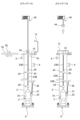
- FIG. 19 is a schematic diagram showing a conventional example of a liquefied gas storage tank in which liquefied gas is stored and a pump for pumping up the liquefied gas.
- Pump 500 is installed in a vertical pump column 505 installed in liquefied gas storage tank 501. The upper end opening of the pump column 505 is closed with an upper lid 510. The inside of pump column 505 is filled with liquefied gas, and the entire pump 500 is immersed in the liquefied gas. Therefore, pump 500 is a submersible pump that can be operated in liquefied gas.
- the liquefied gas in the liquefied gas storage tank 501 is sucked into the pump column 505, moves up the pump column 505, and is discharged from the pump column 505 through the liquefied gas discharge port 509.
- the pump column 505 is provided with a purge gas introduction port 512. This purge gas introduction port 512 is closed when the pump 500 is in operation.
- FIG. 20 is a diagram illustrating the work of carrying the pump 500 into the pump column 505 and the work of lifting the pump 500 from the pump column 505.
- the pump 500 is installed in the pump column 505 and when the pump 500 is lifted from the pump column 505 for purposes such as maintenance, the top cover 510 is removed and the cable 508 is connected to the hoist 513.
- Pump 500 is suspended from cable 508 and raised or lowered within pump column 505 by hoist 513 .
- the liquefied gas remaining in the pump column 505 is gasified to form boil-off gas (BOG).
- purge gas is introduced into the pump column 505 through the purge gas introduction port 512 to prevent this boil-off gas (BOG) from being released into the atmosphere.
- the purge gas also has the role of preventing air from entering into the pump column 505.
- An inert gas such as N 2 gas or He gas is used as the purge gas.
- the present invention aims to reduce the amount of purge gas used to prevent boil-off gas (BOG) from being released from the pump column when a submersible pump is brought into the pump column and withdrawn from the pump column.
- BOG boil-off gas
- the invention also provides a method for installing a submersible pump in a pump column and a method for removing a submersible pump from a pump column using such a pump installation device.
- a pump installation device for installing and removing a submersible pump used for transferring liquefied gas into and from a pump column, the device comprising: a work chamber forming a closed work space; , an actuator-driven door covering an upper opening of the pump column, a suspension cable for suspending the submersible pump within the pump column, and a crane for raising and lowering the suspension cable,
- a pump installation arrangement is provided, wherein the pump column top opening, the actuator-driven door, and the crane are located within the workspace.
- the suspension cable includes a plurality of split suspension cables and a plurality of connection links that connect the plurality of split suspension cables
- the pump installation device operates the connection links to
- the apparatus further includes a link operating device that causes the connecting link to connect and disconnect the split suspension cables.
- the work chamber includes a purge gas inlet port communicating with the work space and a purge gas supply line coupled to the purge gas inlet port.
- the pump installation device includes a first electrical contact electrically connected to a motor of the submersible pump, and a second electrical contact fixed to the pump column and in contact with the first electrical contact. and a power cable electrically connected to the second electrical contact.
- a method for installing a submersible pump used for transferring liquefied gas in a pump column the actuator drive being located in a closed working space formed by a working chamber.
- the mold door is opened, the actuator-driven door is connected to the top of the pump column, a suspension cable is connected to the submersible pump in the work space, and a crane located in the work space is operated. , lowering the suspension cable and the submersible pump within the pump column, the upper opening of the pump column being disposed within the working space.
- the suspension cable includes a plurality of split suspension cables and a plurality of connection links that connect the plurality of split suspension cables, and the suspension cable and the submersible pump are connected within the pump column.
- the step of lowering the plurality of split suspension cables and the submersible pump are moved to the pump column by the crane while operating the connecting links using a link operating device to connect the plurality of split suspension cables one by one. This is the process of lowering it within the interior.
- the method includes supplying a purge gas into the work space and exposing the submersible pump to the purge gas in the work space before carrying the submersible pump into the pump column. It further includes a step.
- the method includes, when the suspension cable and the submersible pump are lowered within the pump column, the first electrical contact electrically connected to the motor of the submersible pump. The method further includes contacting a second electrical contact secured to the pump column.
- a method for retrieving a submersible pump used for transferring liquefied gas from a pump column comprising: an actuator-driven door disposed within an enclosed work space formed by a work chamber; the actuator-driven door is connected to the upper part of the pump column, and the lifting cable connected to the submersible pump is pulled up by a crane disposed within the work space. raising a suspension cable and the submersible pump within the pump column, separating the suspension cable from the submersible pump, and raising the submersible pump from the pump column into the work space using the crane; wherein the upper opening of the pump column is disposed within the working space.
- the suspension cable includes a plurality of split suspension cables and a plurality of connection links that connect the plurality of split suspension cables, and the suspension cable and the submersible pump are connected within the pump column.
- the plurality of divided suspension cables and the submerged pump are moved into the pump column by the crane while operating the connecting links with the link operating device and separating the plurality of divided suspension cables one by one. This is the process of raising the temperature.
- the method includes supplying a purge gas into the work space to move the submersible pump into the work space after the submersible pump is raised from the pump column into the work space.
- the method further includes the step of exposing to purge gas.
- the method includes, when the suspension cable and the submersible pump are raised within the pump column, the first electrical contact electrically connected to the motor of the submersible pump.
- the method further includes disconnecting from a second electrical contact secured to the pump column.
- the submersible pump can be automatically installed on and lifted from the pump column. Therefore, workers are not exposed to a hazardous atmosphere. Also, since the top opening of the pump column is in a closed working space, no boil-off gas (BOG) is released to the atmosphere. As a result, the amount of purge gas used to prevent boil-off gas (BOG) from being released into the atmosphere can be reduced to substantially zero. Furthermore, when the submersible pump is carried into the pump column, by filling the working space with a gas consisting of the same components as the liquefied gas, gases containing other components such as air can be prevented from entering the pump column. I can do it.
- a gas consisting of the same components as the liquefied gas gases containing other components such as air can be prevented from entering the pump column. I can do it.
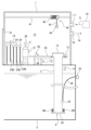
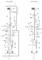
- FIG. 1 illustrates an embodiment of a pump system for transporting liquefied gas.
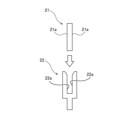
- FIG. 2A is a view of the first electrical contact and the second electrical contact from the radial direction of the pump column.
- FIG. 2B is a view of the first electrical contact and the second electrical contact from the radial direction of the pump column.
- FIG. 3 is a cross-sectional view showing one embodiment of a connecting link.
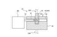
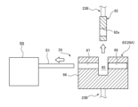
- FIG. 4A is a diagram illustrating how the first link mechanism is connected to the second link mechanism by the link operating device.
- FIG. 4B is a diagram illustrating how the first link mechanism is connected to the second link mechanism by the link operating device.
- FIG. 5A is a diagram illustrating how the first link mechanism is separated from the second link mechanism by the link operating device.
- FIG. 5B is a diagram illustrating how the first link mechanism is separated from the second link mechanism by the link operating device. It is a top view showing one embodiment of a support plate. It is a figure which shows the state before a suspension cable and a submersible pump are carried into a pump column.
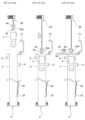
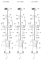
- FIG. 2 is a diagram illustrating an embodiment of a method for installing a submersible pump in a pump column.
- FIG. 2 is a diagram illustrating an embodiment of a method for installing a submersible pump in a pump column.
- FIG. 2 is a diagram illustrating an embodiment of a method for installing a submersible pump in a pump column.
- FIG. 2 is a diagram illustrating an embodiment of a method for installing a submersible pump in a pump column.
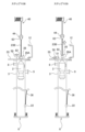
- FIG. 2 is a diagram illustrating an embodiment of a method for installing a submersible pump in a pump column.
- FIG. 2 is a diagram illustrating an embodiment of a method for installing a submersible pump in a pump column.
- FIG. 2 is a diagram illustrating an embodiment of a method for installing a submersible pump in a pump column.
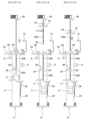
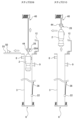
- FIG. 3 is a diagram illustrating an embodiment of a method for removing a submersible pump from a pump column.
- FIG. 3 is a diagram illustrating an embodiment of a method for removing a submersible pump from a pump column.
- FIG. 3 is a diagram illustrating an embodiment of a method for removing a submersible pump from a pump column.
- FIG. 3 is a diagram illustrating an embodiment of a method for removing a submersible pump from a pump column.
- FIG. 3 is a diagram illustrating an embodiment of a method for removing a submersible pump from a pump column.
- FIG. 1 is a schematic diagram showing a conventional example of a liquefied gas storage tank in which liquefied gas is stored and a pump for pumping up liquefied gas.
- FIG. 6 is a diagram illustrating the work of carrying the pump into the pump column and the work of lifting the pump from the pump column.
- FIG. 1 is a diagram illustrating one embodiment of a pump system for transporting liquefied gas.
- liquefied gases transferred by the pump system shown in FIG. 1 include liquefied ammonia, liquid hydrogen, liquid nitrogen, liquefied natural gas, liquefied ethylene gas, liquefied petroleum gas, and the like.
- the pump system includes a submersible pump 2 for transferring liquefied gas, a pump column 3 in which the submersible pump 2 is housed, and a head that closes the upper opening of the pump column 3.
- a plate 10 is provided.
- the pump column 3 is installed in a liquefied gas storage tank 5 in which liquefied gas is stored.
- the pump column 3 is a hollow container extending in the vertical direction, and its upper portion projects upward from the liquefied gas storage tank 5.
- the pump column 3 has a purge gas introduction port 8 and a discharge port 9.
- the discharge port 9 is connected to a transfer pipe (not shown) extending from the inside of the liquefied gas storage tank 5 to the outside.
- a suction valve 6 is provided at the bottom of the pump column 3.
- the submersible pump 2 is installed on the suction valve 6 of the pump column 3.
- the suction valve 6 has a valve body 6A that covers the lower opening of the pump column 3, and a plurality of springs 6B that bias the valve body 6A upward.
- the valve body 6A is pressed against the lower end of the pump column 3 by the plurality of springs 6B, closing the lower opening of the pump column 3.
- the suction valve 6 may be an actuator-driven valve (for example, an electric valve).
- the head plate 10 is placed at the upper end of the pump column 3.
- the head plate 10 is covered by an actuator-driven door 12.
- Suspension cable 23 and connection structure 28 are suspended from head plate 10 .
- the suspension cable 23 extends vertically within the pump column 3.
- the suspension cable 23 includes a plurality of split suspension cables 23B connected by connection links 24.
- the connecting structure 28 is attached to the submersible pump 2.
- the connecting structure 28 is connected to the lower end of the suspension cable 23. More specifically, the connection structure 28 includes a link mechanism 28A that is connected to the suspension cable 23, and a connection member 28B that connects the link mechanism 28A and the submersible pump 2.
- the connecting member 28B may be a cable, a rod-shaped member, or the like.
- the link mechanism 28A has a wider width than the connecting member 28B.
- An electrical terminal 35 is attached to the side wall of the liquefied gas storage tank 5. This electrical terminal 35 is connected to a power source (not shown).
- a first electrical contact 21 electrically connected to the electric motor 2a is fixed to the submersible pump 2, and a second electrical contact 22 that contacts the first electrical contact 21 is provided on the side wall of the pump column 3. It is provided.
- a power cable 36 for supplying power to the electric motor 2 a of the submersible pump 2 extends from the electrical terminal 35 to the second electrical contact 22 .
- the first electrical contact 21 is fixed to the outer surface of the submersible pump 2 and protrudes radially outward from the outer surface of the submersible pump 2.
- the second electrical contact 22 is located radially outward of the submersible pump 2.
- the first electrical contact 21 is movable together with the submersible pump 2, while the position of the second electrical contact 22 is fixed.
- Part of the second electrical contact 22 is located outside the pump column 3, and the entire power cable 36 is located outside the pump column 3.
- the second electrical contact 22 extends through the side wall of the pump column 3.
- the second electrical contact 22 therefore has an outer part located outside the pump column 3 and an inner part located within the pump column 3.
- the end of power cable 36 is connected to the outer portion of second electrical contact 22 .
- the liquefied gas used in this embodiment has electrical insulation properties. Therefore, no leakage occurs through the first electrical contact 21 and the second electrical contact 22.
- the second electrical contact 22 may be disposed entirely within the pump column 3 and the power cable 36 may extend through the side wall of the pump column 3 to the second electrical contact 22.
- the first electrical contact 21 is movable together with the submersible pump 2 and movable relative to the second electrical contact 22.
- the first electrical contacts 21 can contact the second electrical contacts 22 when the submersible pump 2 is lowered within the pump column 3 .
- the first electrical contact 21 contacts the second electrical contact 22. This establishes an electrical connection between the first electrical contact 21 and the second electrical contact 22. Electric power is supplied from the power cable 36 to the electric motor 2a of the submersible pump 27 via the second electrical contact 22 and the first electrical contact 21, thereby operating the submersible pump 2.
- FIG. 2A is a diagram of the first electrical contact 21 and the second electrical contact 22 viewed from the radial direction of the pump column 3.
- the first electrical contact 21 has a first contact surface 21a extending along the longitudinal direction of the pump column 3.
- the second electrical contact 22 has a second contact surface 22a extending along the longitudinal direction of the pump column 3.
- the first electrical contact 21 has a flat plate shape
- the second electrical contact 22 has a clamp shape that holds the first electrical contact 21 therebetween.
- the second electrical contact 22 has a flat plate shape
- the first electrical contact 21 may have a clamp shape that holds the second electrical contact 22 therebetween.
- the first electrical contact 21 can be moved toward the second electrical contact 22 until the first contact surface 21a contacts the second contact surface 22a.
- the first contact surface 21a and the second contact surface 22a are parallel to each other and extend in the longitudinal direction of the pump column 3. Therefore, the first electrical contact 21 and the second electrical contact 22 are movable relative to each other in the longitudinal direction of the pump column 3 while in contact with each other.
- the liquefied gas in the liquefied gas storage tank 5 is introduced into the pump column 3 through the suction valve 6, and the pump column 3 is filled with liquefied gas.
- the entire submersible pump 2 is immersed in the liquefied gas. Therefore, the submersible pump 2 is configured to be operable in liquefied gas.
- the liquefied gas pressurized by the submersible pump 2 is transferred to the outside through the discharge port 9 and a transfer pipe (not shown). While the submersible pump 2 is in operation, the purge gas introduction port 8 is closed by a valve (not shown).
- the pump system includes a pump installation device as described below.
- the pump installation device includes a work chamber 1 forming a closed work space 15, the actuator-driven door 12 that covers the upper opening 3a of the pump column 3, and a submersible pump 2 for suspending it inside the pump column 3.
- the suspension cable 23, a crane 40 for raising and lowering the suspension cable 23, the first electrical contact 21 and the second electrical contact 22 are provided.
- the upper opening 3a of the pump column 3, the actuator-driven door 12, and the crane 40 are arranged within the working space 15.
- the work chamber 1 has a work door 16 for carrying the submersible pump 2, suspension cable 23, etc. into and out of the work space 15. This work door 16 is normally closed.
- the working chamber 1 is fixed to the upper wall 5A of the liquefied gas storage tank 5.
- the working chamber 1 has a purge gas inlet port 17 and a gas outlet port 18 communicating with its working space 15 .
- a purge gas supply line 71 extending from a purge gas supply source 70 is connected to the purge gas inlet port 17 , and a vacuum line 74 is connected to the gas outlet port 18 .
- Vacuum line 74 is connected to a vacuum source (not shown) such as a vacuum pump.
- purge gas sources 70 include nitrogen gas sources, helium gas sources, hydrogen gas sources, or combinations thereof.
- purge gas source 70 may include a plurality of different types of purge gas sources, such as at least two of a nitrogen gas source and a helium gas source and a hydrogen gas source. In this case, a plurality of purge gas supply sources may be selectively connected to the purge gas supply line 71.
- the purge gas used is a gas consisting of a component having a boiling point lower than the boiling point of the liquefied gas to be pumped by the submersible pump 2. This is to prevent the purge gas from being liquefied when it comes into contact with the liquefied gas.
- purge gas include inert gases such as nitrogen gas and helium gas.
- nitrogen gas is a gas consisting of nitrogen that has a boiling point (-196°C) lower than the boiling point (-162°C) of liquefied natural gas. is used as purge gas.
- helium gas which is a gas made of helium with a boiling point (-269°C) lower than the boiling point of hydrogen (-253°C), is used. is used as purge gas.
- a part of the purge gas may be a gas consisting of the same components as the liquefied gas. If the gas outlet port 18 is connected to a gas treatment device, all of the purge gas may be of the same composition as the liquefied gas. For example, if the liquefied gas is liquid hydrogen, part or all of the purge gas may be hydrogen gas. In other examples, if the liquefied gas is liquefied ammonia, some or all of the purge gas may be ammonia gas.
- the actuator-driven door 12 is connected to the top of the pump column 3.
- the actuator-driven door 12 covers the upper opening 3a of the pump column 3 and the head plate 10 that closes the upper opening 3a.
- the actuator-driven door 12 includes an actuator 13 such as an electric motor or an air cylinder.
- the actuator-driven door 12 is configured to open and close in response to a command signal transmitted from outside the work chamber 1 . During operation of the submersible pump 2, the actuator-driven door 12 is closed, as shown in FIG.
- the actuator-driven door 12 When the actuator-driven door 12 is closed, a sealed space is formed between the actuator-driven door 12 and the top of the pump column 3. The head plate 10 is located within this sealed space.
- the actuator-driven door 12 can prevent boil-off gas (BOG) that has passed through the small gap between the head plate 10 and the top of the pump column 3 from leaking into the work space 15 of the work chamber 1. .
- BOG boil-off gas
- the crane 40 is configured to be movable in the work space 15. More specifically, the crane 40 is movable on a support rail 41 located within the work space 15, as indicated by the arrow. The crane 40 can move between a position above the pump column 3 and a position remote from the pump column 3.
- the crane 40 includes a gripping mechanism 44, a wire 45 for suspending the gripping mechanism 44, and a hoist 46 that lets out and winds up the wire 45.
- the gripping mechanism 44 is configured to be able to grip the head plate 10, the suspension cable 23, the connecting link 24, the connecting structure 28, and the like. Examples of the hoist 46 include a hoist, a winch, and the like.
- the crane 40 is configured to operate in response to a command signal transmitted from outside the work chamber 1.
- the suspension cable 23 includes a plurality of split suspension cables 23B and a plurality of connection links 24 that connect these split suspension cables 23B. In FIG. 1, only one connecting link 24 is depicted. The length of each split suspension cable 23B is shorter than the length of the pump column 3. The plurality of split suspension cables 23B are connected in series by connection links 24.
- the pump installation device includes a link operating device 50 that connects and disconnects the split suspension cables 23B by operating each connecting link 24, a support plate 55 that supports the link operating device 50, and a support plate 55 that is positioned directly above the pump column 3. It further includes a plate actuator 58 that moves the plate actuator between the and the retracted position.
- the link operating device 50 is arranged on a support plate 55, and the support plate 55 is connected to a plate actuator 58.
- the plate actuator 58 can move the link operating device 50 and the support plate 55 together.
- the link operating device 50 includes an actuator 52 such as a linear motor or an air cylinder, and is configured to be movable on a support plate 55. That is, the link operating device 50 is movable relative to the support plate 55.
- the link operating device 50 has an operating pin 51 that protrudes toward the connecting link 24. When the connecting link 24 is operated by this operation pin 51, the connecting link 24 is configured to connect or disconnect the split suspension cable 23B.
- FIG. 3 is a sectional view showing one embodiment of the connecting link 24.
- the connecting link 24 includes a first link mechanism 62 and a second link mechanism 63.
- the first link mechanism 62 and the second link mechanism 63 are connected to both ends of each split suspension cable 23B.
- the first link mechanism 62 is connected to the lower end of each divided suspension cable 23B
- the second link mechanism 63 is connected to the upper end of each divided suspension cable 23B.
- the second link mechanism 63 has a wider width than the first link mechanism 62. Since the link mechanism 28A of the connected structure 28 shown in FIG. 1 has the same configuration as the second link mechanism 63, the following description also applies to the link mechanism 28A of the connected structure 28.
- the first link mechanism 62 has a first horizontal hole 62a that extends horizontally.
- the second link mechanism 63 includes a housing 66 having a recess 65 in which the first link mechanism 62 is housed, and a connecting pin 68 housed in a second horizontal hole 67 formed in the housing 66.
- the connecting pin 68 is movable within the second horizontal hole 67.
- the second horizontal hole 67 passes through the housing 66 in the horizontal direction.
- the diameter of the first lateral hole 62a of the first link mechanism 62 is larger than the diameter of the connecting pin 68, and the connecting pin 68 can pass through the first lateral hole 62a of the first link mechanism 62.
- FIGS. 4A and 4B are diagrams illustrating how the first link mechanism 62 is connected to the second link mechanism 63 by the link operating device 50.
- the connecting pin 68 when the connecting pin 68 is located outside the recess 65, the first link mechanism 62 enters into the recess 65 of the second link mechanism 63.
- FIG. 4B when the first lateral hole 62a of the first link mechanism 62 and the second lateral hole 67 of the second link mechanism 63 are lined up in a straight line, the link operating device 50 Moving toward the link mechanism 63, the operating pin 51 of the link operating device 50 pushes the connecting pin 68 into the first horizontal hole 62a. The connecting pin 68 moves into the first horizontal hole 62a, thereby connecting the first link mechanism 62 and the second link mechanism 63.
- FIGS. 5A and 5B are diagrams illustrating how the first link mechanism 62 is separated from the second link mechanism 63 by the link operating device 50.
- the link operating device 50 moves toward the second link mechanism 63 of the connecting link 24, and the operating pin 51 of the link operating device 50 pushes the connecting pin 68 out of the first horizontal hole 62a.
- the operating pin 51 of the link operating device 50 is pulled out from the first lateral hole 62a and the second lateral hole 67, and the first link mechanism 62 is separated from the second link mechanism 63.
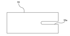
- FIG. 6 is a top view showing one embodiment of the support plate 55 shown in FIG. 1.
- the support plate 55 has a horizontally long notch 55a.
- the width of this notch 55a is larger than the width of the split suspension cable 23B and the width of the connecting member 28B of the connecting structure 28, and the width of the second link mechanism 63 of the connecting link 24 and the link mechanism of the connecting structure 28. It is smaller than the width of 28A. Therefore, the split suspension cable 23B and the connecting member 28B of the connecting structure 28 can pass through the notch 55a, but the second link mechanism 63 of the connecting link 24 and the link mechanism 28A of the connecting structure 28 can pass through the notch. 55a cannot be passed.
- FIG. 7 is a diagram showing a state before the suspension cable 23 and the submersible pump 2 are carried into the pump column 3.
- the plurality of split suspension cables 23B constituting the suspension cable 23 and the submersible pump 2 are arranged at a location away from the pump column 3 in the work space 15 of the work chamber 1.
- a connecting structure 28 and a first electrical contact 21 are attached to the submersible pump 2 in advance.
- a connecting link 24 is attached in advance to each split suspension cable 23B, and a head plate 10 is attached in advance to one split suspension cable 23B.
- the valve body 6A of the suction valve 6 is pressed against the lower end of the pump column 3 by a plurality of springs 6B, thereby closing the lower opening of the pump column 3.
- FIGS. 7 to 13 The series of operations shown in FIGS. 7 to 13 includes an operation of lowering the submersible pump 2 within the pump column 3, and an operation of adding a plurality of split suspension cables 23B to the suspension cable 23 one by one.
- the liquefied gas is discharged from the pump column 3. Specifically, with the actuator-driven door 12 open, purge gas is supplied into the work space 15 through the purge gas inlet port 17 to increase the pressure within the pump column 3, thereby removing the liquefied gas from the pump column 3. It is discharged through the suction valve 6. Thereafter, the actuator-driven door 12 is closed.
- step 101 as shown in FIG. 7, with the upper opening 3a of the pump column 3 closed by the actuator-driven door 12, the work space 15 in the work chamber 1 in which the submersible pump 2 is accommodated is gassed. A vacuum is drawn through outlet port 18. Thereafter, a purge gas (eg, including an inert gas and/or a gas having the same components as the liquefied gas) is supplied to the work space 15 from the purge gas inlet port 17 to fill the work space 15 with the purge gas.
- the submersible pump 2 is exposed to (contacts) a purge gas within the working space 15, thereby removing air and moisture from the surfaces of the submersible pump 2.
- This step is a dry-up that drives air and moisture out of the submersible pump 2. Evacuation of the work space 15 and supply of purge gas to the work space 15 may be repeated.
- step 102 the actuator-driven door 12 is opened and the submersible pump 2 is transported to a position above the pump column 3 by the crane 40. More specifically, the gripping mechanism 44 of the crane 40 grips the link mechanism 28A of the connecting structure 28 connected to the submersible pump 2, and the crane 40 holds the submersible pump 2 and the connecting structure 28. They are transported together to a position above the pump column 3.
- step 103 the submersible pump 2 and the connecting structure 28 are lowered together by the crane 40, and the submersible pump 2 is moved into the pump column 3, while the link mechanism 28A of the connecting structure 28 is lowered. It is located above the pump column 3.
- step 104 with the link mechanism 28A of the connecting structure 28 above the pump column 3, the plate actuator 58 (see FIG. 1) moves the support plate 55 and the link operating device 50 toward the pump column 3 to support the pump column 3.
- the plate 55 covers the upper opening 3a of the pump column 3.
- the support plate 55 has a notch 55a, and the width of the notch 55a is larger than the width of the connecting member 28B of the connecting structure 28, and the width of the link mechanism 28A. smaller than In step 104 shown in FIG. 8, the support plate 55 is moved onto the pump column 3 so that the connecting member 28B is located within the notch 55a of the support plate 55.
- step 105 the crane 40 further lowers the connecting structure 28 and the submersible pump 2 until the link mechanism 28A of the connecting structure 28 contacts the support plate 55.
- the submersible pump 2 is suspended from the support plate 55 by the connecting structure 28 . That is, the load of the submersible pump 2 is supported by the support plate 55.
- step 106 the gripping mechanism 44 of the crane 40 releases the link mechanism 28A of the connecting structure 28, and then the crane 40 releases one of the plurality of split suspension cables 23B (see FIG. 7) prepared in advance. , and transported to a position above the pump column 3.
- the second link mechanism 63 of the connection link 24 is attached in advance to the upper end of the split suspension cable 23B, and the first link mechanism 62 of the connection link 24 is attached to the lower end of the split suspension cable 23B.
- step 107 the split suspension cable 23B continues until the first link mechanism 62 attached to the lower end of the split suspension cable 23B enters the recess 65 (see FIG. 4A) of the link mechanism 28A on the support plate 55. It is lowered by a crane 40.
- step 108 the link operating device 50 moves toward the link mechanism 28A on the support plate 55, and moves the connecting pin 68 of the link mechanism 28A into the first horizontal hole 62a using the operating pin 51 of the link operating device 50 ( (see Figure 4B). Thereby, the first link mechanism 62 is connected to the link mechanism 28A, and the split suspension cable 23B is connected to the connection structure 28.
- step 109 the link operating device 50 moves away from the link mechanism 28A until the operating pin 51 of the link operating device 50 is located outside the link mechanism 28A. Thereafter, the crane 40 pulls up the split suspension cable 23B, the connecting structure 28, and the submersible pump 2 a little. The load of the submersible pump 2 is supported by a crane 40.
- step 110 the plate actuator 58 (see FIG. 1) moves the support plate 55 and the link operating device 50 in a direction away from the pump column 3. Subsequently, the split suspension cable 23B, the connecting structure 28, and the submersible pump 2 are lowered by the crane 40, and the submersible pump 2 is moved into the pump column 3, while the second The link mechanism 63 is located above the pump column 3.
- step 111 before the second link mechanism 63 attached to the uppermost split suspension cable 23B enters the pump column 3, the support plate 55 and the link operating device 50 are pumped by the plate actuator 58 (see FIG. 1). It is moved towards the column 3 and the upper opening 3a of the pump column 3 is covered with the support plate 55. As described with reference to FIG. 6, the width of the notch 55a of the support plate 55 is larger than the width of the split suspension cable 23B and smaller than the width of the second link mechanism 63. In step 111 shown in FIG. 11, the support plate 55 is moved onto the pump column 3 so that the split suspension cable 23B is located within the notch 55a of the support plate 55.
- step 112 the crane 40 moves the split suspension cable 23B, the connecting structure 28, and the submersible pump 2 until the second link mechanism 63 attached to the uppermost split suspension cable 23B contacts the support plate 55. It is further lowered in the pump column 3. The submersible pump 2 is suspended from the support plate 55 by the split suspension cable 23B and the connecting structure 28. That is, the load of the submersible pump 2 is supported by the support plate 55.
- steps similar to the above steps 106 to 112 are repeated while adding the remainder of the plurality of split suspension cables 23B one by one. That is, while operating the link operating device 50 to connect the plurality of split suspension cables 23B one by one, the crane 40 moves the plurality of split suspension cables 23B and the submersible pump 2 within the pump column 3. lower it.
- step 113 the last split suspension cable 23B is added to the suspension cable 23 when the submersible pump 2 approaches the bottom of the pump column 3.
- the head plate 10 is connected in advance to the upper end of this last split suspension cable 23B.
- step 114 as described with reference to FIGS. 4A and 4B, the first link mechanism 62 attached to the lower end of the uppermost split suspension cable 23B and the second link mechanism 63 on the support plate 55 are connected. Connect.
- step 115 the plate actuator 58 (see FIG. 1) moves the support plate 55 and the link operating device 50 in a direction away from the pump column 3. Subsequently, the split suspension cable 23B, the connecting structure 28, and the submersible pump 2 are lowered by the crane 40, the upper opening 3a of the pump column 3 is closed with the head plate 10, and the submersible pump 2 is opened to the suction Placed on valve 6. The suction valve 6 opens due to the weight of the submersible pump 2. At the same time, the first electrical contact 21 fixed on the submersible pump 2 contacts the second electrical contact 22 fixed on the pump column 3, thereby connecting the electric motor 2a of the submersible pump 2 with the power cable An electrical connection is established with 36.
- step 116 the gripping mechanism 44 of the crane 40 is released from the head plate 10 and the actuator-driven door 12 is closed. This completes the installation of the submersible pump 2 on the pump column 3.
- a worker can automatically install the submersible pump 2 on the pump column 3 by remotely controlling the crane 40, link operating device 50, and actuator-driven door 12 from outside the work chamber 1. . Therefore, workers are not exposed to a dangerous atmosphere. Furthermore, since the upper opening 3a of the pump column 3 is located within the closed working space 15, boil-off gas (BOG) is not released to the atmosphere. As a result, the amount of purge gas used to prevent boil-off gas (BOG) from being released into the atmosphere can therefore be substantially zero. Furthermore, when the submersible pump 2 is carried into the pump column 3, by filling the working space 15 with a gas consisting of the same components as the liquefied gas, gas containing other components such as air can be transferred to the pump column 3. Entry can be prevented.
- a gas consisting of the same components as the liquefied gas gas containing other components such as air can be transferred to the pump column 3. Entry can be prevented.
- FIGS. 1 and 14 to 18 an embodiment of a method for taking out the submersible pump 2 from the pump column 3 will be described with reference to FIGS. 1 and 14 to 18.
- the series of operations shown in FIGS. 1, 14 to 18 includes an operation of raising the submersible pump 2 within the pump column 3, and an operation of removing the plurality of split suspension cables 23B from the suspension cable 23 one by one.
- step 201 as shown in FIG. Pull.
- a purge gas including, for example, an inert gas and/or a gas having the same components as the liquefied gas
- Evacuation of the work space 15 and supply of purge gas to the work space 15 may be repeated.
- step 202 the actuator-driven door 12 is opened, as shown in FIG.
- the head plate 10 is gripped by the gripping mechanism 44 of the crane 40, and the crane 40 pulls up the head plate 10, the split suspension cable 23B, the connecting structure 28, and the submersible pump 2 a little, and the suction valve 6 is closed.
- the submersible pump 2 is lifted from its operating position (the position of the submersible pump 2 shown in FIG.
- the electrical connection between the electric motor 2a and the power cable 36 is cut off.
- purge gas is supplied into the working chamber 1 through the purge gas inlet port 17 to increase the pressure within the pump column 3.
- purge gas inlet port 17 As the pressure within the pump column 3 increases, liquefied gas is discharged from the pump column 3 through the suction valve 6.
- step 203 the plurality of split suspension cables 23B, the connecting structure 28, and the submersible pump 2 are lifted up by the crane 40 until the entire uppermost split suspension cable 23B is located above the pump column 3. Thereafter, the support plate 55 and the link operating device 50 are moved toward the pump column 3 by the plate actuator 58 (see FIG. 1), and the support plate 55 covers the upper opening 3a of the pump column 3.
- step 204 the crane 40 lowers the split suspension cable 23B, the connecting structure 28, and the submersible pump 2 a little until the second link mechanism 63 located directly above the support plate 55 comes into contact with the support plate 55.
- the submersible pump 2 is suspended from the support plate 55 by the split suspension cable 23B and the connecting structure 28. That is, the load of the submersible pump 2 is supported by the support plate 55.
- step 205 the link operating device 50 moves toward the second link mechanism 63 on the support plate 55, and the operating pin 51 of the link operating device 50 moves the connecting pin 68 of the second link mechanism 63 out of the first horizontal hole 62a.
- step 206 the link operating device 50 separates from the second link mechanism 63 on the support plate 55 (see FIG. 5B). Thereby, the first link mechanism 62 is separated from the second link mechanism 63, and the uppermost split suspension cable 23B can be separated from the other split suspension cables 23B.
- step 207 the crane 40 pulls up the uppermost split suspension cable 23B and moves it further away from the pump column 3 (see FIG. 7).
- step 208 the second link mechanism 63 on the support plate 55 is grasped by the crane 40.
- steps similar to steps 203 to 207 are repeated while removing the plurality of split suspension cables 23B one by one until all the split suspension cables 23B are removed by the crane 40. That is, while operating the connecting links 21 using the link operating device 50 and separating the plurality of split suspension cables 23B one by one, the crane 40 lifts the plurality of split suspension cables 23B and the submersible pump 2 within the pump column 3. let When all the split suspension cables 23B are removed, the link mechanism 28A of the connection structure 28 attached to the submersible pump 2 is supported by the support plate 55.
- step 209 the link mechanism 28A of the connecting structure 28 is gripped by the gripping mechanism 44, and the connecting structure 28 and the submersible pump 2 are slightly lifted up by the crane 40. Subsequently, the support plate 55 and the link operating device 50 are moved in a direction away from the pump column 3 by the plate actuator 58 (see FIG. 1).
- step 210 the crane 40 lifts the connecting structure 28 and the entire submersible pump 2 from the pump column 3 and transports it to a position away from the pump column 3 (see FIG. 7).
- step 211 the actuator-driven door 12 is closed.
- step 212 as shown in FIG. Then, the working space 15 is filled with purge gas.
- the submersible pump 2 is exposed to (contacts with) the purge gas within the purge container 1, thereby warming the submersible pump 2.
- This step is a hot-up process in which the submersible pump 2 is heated. This completes the removal of the submersible pump 2 from the pump column 3.
- a worker can automatically take out the submersible pump 2 from the pump column 3 by remotely controlling the crane 40, link operating device 50, and actuator-driven door 12 from outside the work chamber 1. . Therefore, workers are not exposed to a dangerous atmosphere. Furthermore, since the upper opening 3a of the pump column 3 is located within the closed working space 15, boil-off gas (BOG) is not released to the atmosphere. As a result, the amount of purge gas used to prevent boil-off gas (BOG) from being released into the atmosphere can therefore be substantially zero. Furthermore, when the submersible pump 2 is lifted from the pump column 3, by filling the working space 15 with a gas consisting of the same components as the liquefied gas, gas containing other components such as air can enter the pump column 3. Entry can be prevented.
- a gas consisting of the same components as the liquefied gas gas containing other components such as air can enter the pump column 3. Entry can be prevented.
- the present invention can be used for a pump installation device for installing a submerged pump in a pump column for boosting the pressure of liquefied gas such as liquefied ammonia, liquefied natural gas (LNG), and liquid hydrogen, and for extracting it from the pump column.
- liquefied gas such as liquefied ammonia, liquefied natural gas (LNG), and liquid hydrogen
- the present invention can be used in a method of installing a submersible pump in a pump column and a method of removing a submersible pump from a pump column using such a pump installation device.
Landscapes
- Engineering & Computer Science (AREA)
- Mechanical Engineering (AREA)
- General Engineering & Computer Science (AREA)
- Structures Of Non-Positive Displacement Pumps (AREA)
- Filling Or Discharging Of Gas Storage Vessels (AREA)
Abstract
ポンプ設置装置は、閉じられた作業空間(15)を形成する作業チャンバ(1)と、ポンプコラム(3)の上部開口(3a)を覆うアクチュエータ駆動型扉(12)と、潜没式ポンプ(2)をポンプコラム(3)内に吊り下げるための吊りケーブル(23)と、吊りケーブル(23)を上昇および下降させるためのクレーン(40)を備えている。ポンプコラム(3)の上部開口(3a)、アクチュエータ駆動型扉(12)、およびクレーン(40)は、作業空間(15)内に配置されている。
Description
本発明は、液化アンモニアや液化天然ガス(LNG)や液体水素などの液化ガスを昇圧するための潜没式ポンプをポンプコラム内に設置、およびポンプコラムから取り出すためのポンプ設置装置に関する。さらに、本発明はそのようなポンプ設置装置を用いて、潜没式ポンプをポンプコラム内に設置する方法、および潜没式ポンプをポンプコラムから取り出す方法に関する。
天然ガスは、火力発電や化学原料として広く利用されている。また、アンモニアや水素は、地球温暖化の原因となる二酸化炭素を発生しないエネルギーとして期待されている。エネルギーとしての水素の用途には、燃料電池およびタービン発電などが挙げられる。天然ガス、アンモニア、および水素は、常温では気体の状態であるため、これらの貯蔵および運搬のために、天然ガス、アンモニア、および水素は冷却され、液化される。液化天然ガス(LNG)や液化アンモニアや液体水素などの液化ガスは、一旦液化ガス貯槽に貯蔵された後、ポンプによって発電所や工場などに移送される。
図19は、液化ガスが貯蔵された液化ガス貯槽と、液化ガスを汲み上げるためのポンプの従来例を示す模式図である。ポンプ500は、液化ガス貯槽501に設置された縦型ポンプコラム505内に設置される。ポンプコラム505の上端開口は、上蓋510で閉じられている。ポンプコラム505内は液化ガスで満たされ、ポンプ500の全体は液化ガス中に浸漬される。したがって、ポンプ500は、液化ガス中で運転可能な潜没式ポンプである。
ポンプ500が運転されると、液化ガス貯槽501内の液化ガスはポンプコラム505内に吸い込まれ、ポンプコラム505を上昇し、そしてポンプコラム505から液化ガス排出ポート509を通じて排出される。ポンプコラム505には、パージガス導入ポート512が設けられている。このパージガス導入ポート512は、ポンプ500の運転時には閉じられている。
図20は、ポンプ500をポンプコラム505内に搬入する作業、およびポンプ500をポンプコラム505から引き上げる作業を説明する図である。ポンプ500をポンプコラム505内に設置するとき、およびメンテナンスなどの目的でポンプ500をポンプコラム505から引き上げるとき、上蓋510が外され、ケーブル508は巻き上げ機513に接続される。ポンプ500はケーブル508に吊り下げられ、巻き上げ機513によってポンプコラム505内を上昇または下降される。
ポンプコラム505内に残留する液化ガスはガス化して、ボイルオフガス(BOG)を形成する。ポンプ500の搬入および引き上げの間は、このボイルオフガス(BOG)が大気に放出されることを防ぐために、パージガス導入ポート512を通じてパージガスがポンプコラム505内に導入される。パージガスは、ポンプコラム505内への空気の侵入を防ぐ役割も持つ。パージガスには、N2ガス、Heガスなどの不活性ガスが使用される。
しかしながら、ポンプコラム505の上部開口は、ポンプ500の幅よりも大きいため、ボイルオフガス(BOG)のポンプコラム505外への放出を防ぎつつ、空気のポンプコラム505内への侵入を防ぐためには、大量のパージガスが必要となる。特に、Heガスは高価であり、ポンプ500の搬入および引き上げ作業のコストが上昇してしまう。
また、ポンプ500の搬入および引き上げ作業時には、作業員はボイルオフガスにさらされる可能性があり、安全な作業環境が確保できないおそれがある。特に、ケーブル508をポンプコラム505から引き上げるとき、液化ガスに接触していたケーブル508は非常に低温であり、ケーブル508の取り扱いには危険を伴う。
そこで、本発明は、潜没式ポンプのポンプコラムへの搬入およびポンプコラムからの引き上げ時に、ボイルオフガス(BOG)のポンプコラムからの放出を防止するために使用されるパージガスの量を削減することができ、さらには安全な作業環境を構築できるポンプ設置装置を提供する。また、本発明は、そのようなポンプ設置装置を用いて、潜没式ポンプをポンプコラム内に設置する方法、および潜没式ポンプをポンプコラムから取り出す方法を提供する。
一態様では、液化ガスを移送するために使用される潜没式ポンプをポンプコラム内に設置および前記ポンプコラムから取り出すためのポンプ設置装置であって、閉じられた作業空間を形成する作業チャンバと、前記ポンプコラムの上部開口を覆うアクチュエータ駆動型扉と、前記潜没式ポンプを前記ポンプコラム内に吊り下げるための吊りケーブルと、前記吊りケーブルを上昇および下降させるためのクレーンを備えており、前記ポンプコラムの上部開口、前記アクチュエータ駆動型扉、および前記クレーンは、前記作業空間内に配置されている、ポンプ設置装置が提供される。
一態様では、前記吊りケーブルは、複数の分割吊りケーブルと、前記複数の分割吊りケーブルを連結する複数の連結リンクを有しており、前記ポンプ設置装置は、前記連結リンクを操作して前記複数の分割吊りケーブルの連結および切り離しを前記連結リンクに実行させるリンク操作装置をさらに備えている。
一態様では、前記作業チャンバは、前記作業空間に連通するパージガス入口ポートと、前記パージガス入口ポートに連結されたパージガス供給ラインを備えている。
一態様では、前記ポンプ設置装置は、前記潜没式ポンプの電動機に電気的に接続された第1電気接点と、前記ポンプコラムに固定され、かつ前記第1電気接点に接触する第2電気接点と、前記第2電気接点に電気的に接続された電力ケーブルを備えている。
一態様では、前記作業チャンバは、前記作業空間に連通するパージガス入口ポートと、前記パージガス入口ポートに連結されたパージガス供給ラインを備えている。
一態様では、前記ポンプ設置装置は、前記潜没式ポンプの電動機に電気的に接続された第1電気接点と、前記ポンプコラムに固定され、かつ前記第1電気接点に接触する第2電気接点と、前記第2電気接点に電気的に接続された電力ケーブルを備えている。
一態様では、液化ガスを移送するために使用される潜没式ポンプをポンプコラム内に設置する方法であって、作業チャンバによって形成された、閉じられた作業空間内に配置されているアクチュエータ駆動型扉を開き、前記アクチュエータ駆動型扉は前記ポンプコラムの上部に連結されており、前記作業空間内で吊りケーブルを前記潜没式ポンプに連結し、前記作業空間内に配置されているクレーンにより、前記吊りケーブルおよび前記潜没式ポンプを前記ポンプコラム内で下降させる工程を含み、前記ポンプコラムの上部開口は、前記作業空間内に配置されている、方法が提供される。
一態様では、前記吊りケーブルは、複数の分割吊りケーブルと、前記複数の分割吊りケーブルを連結する複数の連結リンクを有しており、前記吊りケーブルおよび前記潜没式ポンプを前記ポンプコラム内で下降させる工程は、リンク操作装置により前記連結リンクを操作して前記複数の分割吊りケーブルを1つずつ連結しながら、前記クレーンにより、前記複数の分割吊りケーブルおよび前記潜没式ポンプを前記ポンプコラム内で下降させる工程である。
一態様では、前記方法は、前記潜没式ポンプを前記ポンプコラム内に搬入する前に、前記作業空間内にパージガスを供給して、前記作業空間内で前記潜没式ポンプを前記パージガスにさらす工程をさらに含む。
一態様では、前記方法は、前記吊りケーブルおよび前記潜没式ポンプを前記ポンプコラム内で下降させたときに、前記潜没式ポンプの電動機に電気的に接続された第1電気接点を、前記ポンプコラムに固定されている第2電気接点に接触させる工程をさらに含む。
一態様では、前記方法は、前記潜没式ポンプを前記ポンプコラム内に搬入する前に、前記作業空間内にパージガスを供給して、前記作業空間内で前記潜没式ポンプを前記パージガスにさらす工程をさらに含む。
一態様では、前記方法は、前記吊りケーブルおよび前記潜没式ポンプを前記ポンプコラム内で下降させたときに、前記潜没式ポンプの電動機に電気的に接続された第1電気接点を、前記ポンプコラムに固定されている第2電気接点に接触させる工程をさらに含む。
一態様では、液化ガスを移送するために使用される潜没式ポンプをポンプコラムから取り出す方法であって、作業チャンバによって形成された、閉じられた作業空間内に配置されているアクチュエータ駆動型扉を開き、前記アクチュエータ駆動型扉は前記ポンプコラムの上部に連結されており、前記潜没式ポンプに連結されている吊りケーブルを、前記作業空間内に配置されているクレーンにより引き上げることで、前記吊りケーブルおよび前記潜没式ポンプを前記ポンプコラム内で上昇させ、前記吊りケーブルを前記潜没式ポンプから切り離し、前記クレーンにより前記潜没式ポンプを前記ポンプコラムから前記作業空間内に引き上げる工程を含み、前記ポンプコラムの上部開口は、前記作業空間内に配置されている、方法が提供される。
一態様では、前記吊りケーブルは、複数の分割吊りケーブルと、前記複数の分割吊りケーブルを連結する複数の連結リンクを有しており、前記吊りケーブルおよび前記潜没式ポンプを前記ポンプコラム内で上昇させる工程は、リンク操作装置により前記連結リンクを操作して前記複数の分割吊りケーブルを1つずつ切り離しながら、前記クレーンにより、前記複数の分割吊りケーブルおよび前記潜没式ポンプを前記ポンプコラム内で上昇させる工程である。
一態様では、前記方法は、前記潜没式ポンプを前記ポンプコラムから前記作業空間内に引き上げた後に、前記作業空間内にパージガスを供給して、前記作業空間内で前記潜没式ポンプを前記パージガスにさらす工程をさらに含む。
一態様では、前記方法は、前記吊りケーブルおよび前記潜没式ポンプを前記ポンプコラム内で上昇させたときに、前記潜没式ポンプの電動機に電気的に接続された第1電気接点を、前記ポンプコラムに固定されている第2電気接点から切り離す工程をさらに含む。
一態様では、前記方法は、前記潜没式ポンプを前記ポンプコラムから前記作業空間内に引き上げた後に、前記作業空間内にパージガスを供給して、前記作業空間内で前記潜没式ポンプを前記パージガスにさらす工程をさらに含む。
一態様では、前記方法は、前記吊りケーブルおよび前記潜没式ポンプを前記ポンプコラム内で上昇させたときに、前記潜没式ポンプの電動機に電気的に接続された第1電気接点を、前記ポンプコラムに固定されている第2電気接点から切り離す工程をさらに含む。
本発明によれば、作業チャンバの外からクレーンおよびアクチュエータ駆動型扉を遠隔操作することで、潜没式ポンプのポンプコラムへの設置およびポンプコラムからの引き上げを自動で行うことができる。したがって作業員は危険雰囲気にさらされることがない。また、ポンプコラムの上部開口は、閉じられた作業空間内にあるので、ボイルオフガス(BOG)が大気に放出されることがない。結果として、ボイルオフガス(BOG)の大気への放出を防止するために使用されるパージガスの量を実質的に0にすることができる。さらに、潜没式ポンプのポンプコラムへの搬入時に、液化ガスの成分と同じ成分からなるガスで作業空間を満たすことにより、空気などの他の成分を含むガスのポンプコラムへの進入を防ぐことができる。
以下、本発明の実施形態について図面を参照して説明する。
図1は、液化ガスを移送するためのポンプシステムの一実施形態を示す図である。図1に示すポンプシステムによって移送される液化ガスの例としては、液化アンモニア、液体水素、液体窒素、液化天然ガス、液化エチレンガス、液化石油ガスなどが挙げられる。
図1は、液化ガスを移送するためのポンプシステムの一実施形態を示す図である。図1に示すポンプシステムによって移送される液化ガスの例としては、液化アンモニア、液体水素、液体窒素、液化天然ガス、液化エチレンガス、液化石油ガスなどが挙げられる。
図1に示すように、ポンプシステムは、液化ガスを移送するための潜没式ポンプ2と、潜没式ポンプ2が内部に収容されたポンプコラム3と、ポンプコラム3の上部開口を閉じるヘッドプレート10を備えている。ポンプコラム3は、液化ガスが貯留される液化ガス貯槽5内に設置されている。ポンプコラム3は、鉛直方向に延びた中空状の容器であり、その上部は液化ガス貯槽5から上方に突出している。ポンプコラム3はパージガス導入ポート8および吐出しポート9を有している。吐出しポート9は、液化ガス貯槽5の内部から外部に延びる図示しない移送管に連結されている。
ポンプコラム3の底部には吸込み弁6が設けられている。潜没式ポンプ2はポンプコラム3の吸込み弁6上に設置される。吸込み弁6は、ポンプコラム3の下部開口を覆う弁体6Aと、弁体6Aを上方に付勢する複数のばね6Bを有している。潜没式ポンプ2が弁体6A上の置かれていないときは、弁体6Aは複数のばね6Bによってポンプコラム3の下端に押し付けられ、ポンプコラム3の下部開口を閉じる。潜没式ポンプ2が弁体6A上に置かれると、潜没式ポンプ2の自重により弁体6Aはばね6Bの力に抗って下方に移動し、これにより吸込み弁6が開く。吸込み弁6は、アクチュエータ駆動型弁(例えば電動弁)でもよい。
ヘッドプレート10は、ポンプコラム3の上端に置かれている。ヘッドプレート10は、アクチュエータ駆動型扉12によって覆われている。吊りケーブル23および連結構造体28は、ヘッドプレート10から吊り下げられている。吊りケーブル23は、ポンプコラム3内を鉛直方向に延びている。吊りケーブル23は、連結リンク24によって連結された複数の分割吊りケーブル23Bを有する。
連結構造体28は、潜没式ポンプ2に取り付けられている。連結構造体28は吊りケーブル23の下端に連結されている。より具体的には、連結構造体28は、吊りケーブル23に連結されるリンク機構28Aと、リンク機構28Aと潜没式ポンプ2とを連結する連結部材28Bを備えている。連結部材28Bは、ケーブル、棒状部材などであってもよい。リンク機構28Aは、連結部材28Bよりも広い幅を有している。
液化ガス貯槽5の側壁には電気端子35が取り付けられている。この電気端子35は、図示しない電源に接続されている。潜没式ポンプ2には、その電動機2aに電気的に接続された第1電気接点21が固定されており、ポンプコラム3の側壁には第1電気接点21に接触する第2電気接点22が設けられている。潜没式ポンプ2の電動機2aに電力を供給するための電力ケーブル36は、電気端子35から第2電気接点22まで延びている。
第1電気接点21は、潜没式ポンプ2の外面に固定されており、潜没式ポンプ2の外面からその半径方向外側に突出している。第2電気接点22は、潜没式ポンプ2の半径方向外側に位置している。第1電気接点21は、潜没式ポンプ2と一体に移動可能であり、その一方で、第2電気接点22の位置は固定されている。第2電気接点22の一部はポンプコラム3外に配置されており、電力ケーブル36の全体はポンプコラム3の外に配置されている。第2電気接点22は、ポンプコラム3の側壁を貫通して延びている。したがって、第2電気接点22は、ポンプコラム3の外に位置する外側部分と、ポンプコラム3内に位置する内側部分を有する。電力ケーブル36の端部は、第2電気接点22の外側部分に接続されている。
第1電気接点21および第2電気接点22は、液化ガスに接触しているが、本実施形態で使用される液化ガスは電気絶縁性を有している。したがって、第1電気接点21および第2電気接点22を通じて漏電は起こらない。
図示しないが、他の実施形態では、第2電気接点22の全体がポンプコラム3内に配置され、電力ケーブル36はポンプコラム3の側壁を貫通して第2電気接点22まで延びてもよい。
第1電気接点21は潜没式ポンプ2と一体に移動可能であり、かつ第2電気接点22に対して相対的に移動可能である。第1電気接点21は、潜没式ポンプ2をポンプコラム3内で下降させたときに、第2電気接点22に接触することができる。潜没式ポンプ2がポンプコラム3内の運転位置(図1に示す潜没式ポンプ2の位置)まで下降されたとき、第1電気接点21は第2電気接点22に接触する。これにより第1電気接点21と第2電気接点22の電気的接続が確立される。電力は、電力ケーブル36から第2電気接点22および第1電気接点21を経由して潜没式ポンプ27の電動機2aに供給され、これにより潜没式ポンプ2が作動する。
図2Aは、第1電気接点21および第2電気接点22を、ポンプコラム3の半径方向から見た図である。第1電気接点21は、ポンプコラム3の長手方向に沿って延びる第1接触面21aを有する。同様に、第2電気接点22は、ポンプコラム3の長手方向に沿って延びる第2接触面22aを有する。本実施形態においては、第1電気接点21は平坦な板形状を有しており、第2電気接点22は、第1電気接点21を挟むクランプ形状を有している。一実施形態では、第2電気接点22は平坦な板形状を有しており、第1電気接点21は、第2電気接点22を挟むクランプ形状を有してもよい。
図2Bに示すように、第1接触面21aが第2接触面22aに接触するまで、第1電気接点21を第2電気接点22に向かって移動させることができる。第1接触面21aおよび第2接触面22aは互いに並行であり、かつポンプコラム3の長手方向に延びている。したがって、第1電気接点21および前記第2電気接点22は、互いに接触しつつ、ポンプコラム3の長手方向において互いに相対的に移動可能である。
図1に戻り、潜没式ポンプ2の運転中は、液化ガス貯槽5内の液化ガスは、吸込み弁6を通じてポンプコラム3内に導入され、ポンプコラム3内は液化ガスで満たされる。潜没式ポンプ2の運転中、潜没式ポンプ2の全体は液化ガス中に浸漬される。したがって、潜没式ポンプ2は、液化ガス中で運転可能なように構成されている。潜没式ポンプ2によって昇圧された液化ガスは、吐出しポート9および図示しない移送管を通じて外部に移送される。潜没式ポンプ2の運転中は、パージガス導入ポート8は、図示しない弁により閉じられている。
次に、潜没式ポンプ2をポンプコラム3内に設置およびポンプコラム3から取り出すためのポンプ設置装置について説明する。ポンプシステムは、以下に説明するポンプ設置装置を備えている。ポンプ設置装置は、閉じられた作業空間15を形成する作業チャンバ1と、ポンプコラム3の上部開口3aを覆う上記アクチュエータ駆動型扉12と、潜没式ポンプ2をポンプコラム3内に吊り下げるための上記吊りケーブル23と、吊りケーブル23を上昇および下降させるためのクレーン40と、上記第1電気接点21および上記第2電気接点22を備えている。ポンプコラム3の上部開口3a、アクチュエータ駆動型扉12、およびクレーン40は、作業空間15内に配置されている。作業チャンバ1は、潜没式ポンプ2や吊りケーブル23などを作業空間15内に搬入および作業空間15から搬出するための作業扉16を有している。この作業扉16は、通常は閉じられている。
作業チャンバ1は、液化ガス貯槽5の上壁5Aに固定されている。作業チャンバ1は、その作業空間15に連通するパージガス入口ポート17およびガス出口ポート18を備えている。パージガス入口ポート17には、パージガス供給源70から延びるパージガス供給ライン71が連結され、ガス出口ポート18には、真空ライン74が連結される。真空ライン74は、真空ポンプなどの真空源(図示せず)に接続されている。パージガス供給源70の例としては、窒素ガス供給源、ヘリウムガス供給源、水素ガス供給源、またはこれらの組み合わせが挙げられる。一実施形態では、パージガス供給源70は、異なる種類の複数のパージガス供給源、例えば窒素ガス供給源およびヘリウムガス供給源および水素ガス供給源のうちの少なくとも2つを含んでもよい。この場合は、複数のパージガス供給源は、選択的にパージガス供給ライン71に接続されてもよい。
使用されるパージガスは、潜没式ポンプ2が汲み上げる対象の液化ガスの沸点以下の沸点を持つ成分からなるガスである。これは、パージガスが液化ガスに接触したときに、パージガスが液化しないようにするためである。パージガスの例としては、窒素ガス、ヘリウムガスなどの不活性ガスが挙げられる。例えば、潜没式ポンプ2が汲み上げる対象の液化ガスが液化天然ガスである場合、液化天然ガスの沸点(-162℃)よりも低い沸点(-196℃)を持つ窒素からなるガスである窒素ガスがパージガスに使用される。他の例では、潜没式ポンプ2が汲み上げる対象の液化ガスが液体水素である場合、水素の沸点(-253℃)よりも低い沸点(-269℃)を持つヘリウムからなるガスであるヘリウムガスがパージガスに使用される。
パージガスの一部は、液化ガスの成分と同じ成分からなるガスであってもよい。ガス出口ポート18がガス処理装置に連結されている場合には、パージガスの全ては、液化ガスの成分と同じ成分からなるガスであってもよい。例えば、液化ガスが液体水素である場合は、パージガスの一部または全ては、水素ガスであってもよい。他の例では、液化ガスが液化アンモニアである場合は、パージガスの一部または全てはアンモニアガスであってもよい。
アクチュエータ駆動型扉12は、ポンプコラム3の上部に連結されている。アクチュエータ駆動型扉12は、ポンプコラム3の上部開口3a、およびこの上部開口3aを閉じるヘッドプレート10を覆っている。アクチュエータ駆動型扉12は、電動機またはエアシリンダなどのアクチュエータ13を備えている。アクチュエータ駆動型扉12は、作業チャンバ1の外部から送信された指令信号を受けて、開閉するように構成されている。潜没式ポンプ2の運転中には、図1に示すように、アクチュエータ駆動型扉12は、閉じられている。
アクチュエータ駆動型扉12が閉じられているとき、アクチュエータ駆動型扉12とポンプコラム3の上部との間には、密閉された空間が形成される。ヘッドプレート10は、この密閉された空間内に位置している。アクチュエータ駆動型扉12は、ヘッドプレート10とポンプコラム3の上部との間の微小な隙間を通過したボイルオフガス(BOG)が作業チャンバ1の作業空間15内に漏洩することを防止することができる。
クレーン40は、作業空間15で移動可能に構成されている。より具体的には、クレーン40は、矢印で示すように、作業空間15内に配置された支持レール41上を移動可能である。クレーン40は、ポンプコラム3の上方位置と、ポンプコラム3から離れた位置との間を移動することができる。クレーン40は、把持機構44と、把持機構44を吊り下げるワイヤー45と、ワイヤー45を繰り出し、および巻き取る巻き上げ機46を備えている。把持機構44は、ヘッドプレート10、吊りケーブル23、連結リンク24、連結構造体28などを把持することが可能に構成されている。巻き上げ機46の例としては、ホイスト、ウインチなどが挙げられる。クレーン40は、作業チャンバ1の外部から送信された指令信号を受けて、動作するように構成されている。
吊りケーブル23は、複数の分割吊りケーブル23B、およびこれら分割吊りケーブル23Bを連結する複数の連結リンク24を含む。図1では、1つの連結リンク24のみが描かれている。各分割吊りケーブル23Bの長さは、ポンプコラム3の長さよりも短い。複数の分割吊りケーブル23Bは、連結リンク24により直列に繋がれている。
ポンプ設置装置は、各連結リンク24を操作して、分割吊りケーブル23Bを連結および切り離すリンク操作装置50と、リンク操作装置50を支持する支持プレート55と、支持プレート55をポンプコラム3の直上位置と退避位置との間で移動させるプレートアクチュエータ58をさらに備えている。リンク操作装置50は、支持プレート55上に配置されており、支持プレート55はプレートアクチュエータ58に連結されている。プレートアクチュエータ58は、リンク操作装置50と支持プレート55を一体に移動させることが可能である。さらに、リンク操作装置50は、リニアモータまたはエアシリンダなどのアクチュエータ52を有しており、リンク操作装置50は支持プレート55上で移動可能に構成されている。すなわち、リンク操作装置50は、支持プレート55に対して相対的に移動可能である。
リンク操作装置50は、連結リンク24に向かって突出する操作ピン51を有している。この操作ピン51で連結リンク24が操作されたときに、連結リンク24は分割吊りケーブル23Bを連結し、または切り離すように構成される。
図3は、連結リンク24の一実施形態を示す断面図である。図3に示すように、連結リンク24は、第1リンク機構62と、第2リンク機構63を備えている。第1リンク機構62および第2リンク機構63は、各分割吊りケーブル23Bの両端に接続されている。図3に示す実施形態では、第1リンク機構62は各分割吊りケーブル23Bの下端に接続され、第2リンク機構63は各分割吊りケーブル23Bの上端に接続されている。第2リンク機構63は、第1リンク機構62よりも広い幅を有している。図1に示す連結構造体28のリンク機構28Aは、第2リンク機構63と同じ構成を有しているので、以下の説明は、連結構造体28のリンク機構28Aにも適用される。
第1リンク機構62は、水平に延びる第1横穴62aを有している。第2リンク機構63は、第1リンク機構62が収容される窪み部65を有するハウジング66と、ハウジング66に形成された第2横穴67内に収容された連結ピン68を備えている。連結ピン68は、第2横穴67内を移動可能である。第2横穴67は、ハウジング66を水平方向に貫通している。第1リンク機構62の第1横穴62aの直径は連結ピン68の直径よりも大きく、連結ピン68は第1リンク機構62の第1横穴62aを通過することができる。
図3に示すように、連結ピン68が第1リンク機構62の第1横穴62aを横切って配置されているときは、第1リンク機構62と第2リンク機構63は連結されている。一方、連結ピン68が第1リンク機構62の第1横穴62aの外にあるときは、第1リンク機構62は第2リンク機構63から切り離される。
図4Aおよび図4Bは、リンク操作装置50により第1リンク機構62を第2リンク機構63に連結する様子を説明する図である。図4Aに示すように、連結ピン68が窪み部65の外に位置しているとき、第1リンク機構62は第2リンク機構63の窪み部65内に進入する。第1リンク機構62の第1横穴62aと、第2リンク機構63の第2横穴67が直線状に並んだ状態で、図4Bに示すように、リンク操作装置50は、連結リンク24の第2リンク機構63に向かって移動し、リンク操作装置50の操作ピン51は連結ピン68を第1横穴62a内に押し込む。連結ピン68は第1横穴62a内に移動し、これにより第1リンク機構62と第2リンク機構63が連結される。
図5Aおよび図5Bは、リンク操作装置50により第1リンク機構62を第2リンク機構63から切り離す様子を説明する図である。図5Aに示すように、リンク操作装置50は、連結リンク24の第2リンク機構63に向かって移動し、リンク操作装置50の操作ピン51は連結ピン68を第1横穴62aから押し出す。その後、図5Bに示すように、リンク操作装置50の操作ピン51は第1横穴62aおよび第2横穴67から引き抜かれ、第1リンク機構62は、第2リンク機構63から切り離される。
図6は、図1に示す支持プレート55の一実施形態を示す上面図である。支持プレート55は、横長の切り欠き55aを有している。この切り欠き55aの幅は、分割吊りケーブル23Bの幅および連結構造体28の連結部材28Bの幅よりも大きく、かつ連結リンク24の第2リンク機構63の幅、および連結構造体28のリンク機構28Aの幅よりも小さい。したがって、分割吊りケーブル23Bおよび連結構造体28の連結部材28Bは、切り欠き55aを通過することはできるが、連結リンク24の第2リンク機構63および連結構造体28のリンク機構28Aは、切り欠き55aを通過することができない。
図7は、吊りケーブル23および潜没式ポンプ2がポンプコラム3内に搬入される前の状態を示す図である。図7に示すように、吊りケーブル23を構成する複数の分割吊りケーブル23B、および潜没式ポンプ2は、作業チャンバ1の作業空間15内において、ポンプコラム3から離れた場所に配置されている。潜没式ポンプ2には、連結構造体28および第1電気接点21が予め取り付けられている。各分割吊りケーブル23Bには連結リンク24が予め取り付けられており、1つの分割吊りケーブル23Bにはヘッドプレート10が予め取り付けられている。吸込み弁6の弁体6Aは複数のばね6Bによってポンプコラム3の下端に押し付けられ、ポンプコラム3の下部開口を閉じている。
次に、潜没式ポンプ2をポンプコラム3内に設置する方法の一実施形態について、図7乃至図13を参照して説明する。図7乃至図13に示す一連の動作は、潜没式ポンプ2をポンプコラム3内で下降させる動作と、複数の分割吊りケーブル23Bを1つずつ吊りケーブル23に継ぎ足す動作を含む。以下に説明する動作の前に、ポンプコラム3から液化ガスが排出される。具体的には、アクチュエータ駆動型扉12が開かれた状態で、パージガスをパージガス入口ポート17を通じて作業空間15内に供給し、ポンプコラム3内の圧力を高めることにより、液化ガスをポンプコラム3から吸込み弁6を通じて排出する。その後、アクチュエータ駆動型扉12は閉じられる。
ステップ101では、図7に示すように、ポンプコラム3の上部開口3aがアクチュエータ駆動型扉12で閉じられた状態で、潜没式ポンプ2が収容された作業チャンバ1内の作業空間15をガス出口ポート18を通じて真空引きする。その後、パージガス(例えば、不活性ガス、および/または液化ガスの成分と同じ成分からなるガスを含む)をパージガス入口ポート17から作業空間15に供給し、作業空間15をパージガスで満たす。潜没式ポンプ2は作業空間15内でパージガスにさらされ(接触し)、これによって潜没式ポンプ2の表面から空気および水分が排除される。この工程は、潜没式ポンプ2から空気および水分を追い払うドライアップである。作業空間15の真空引きと、作業空間15へのパージガスの供給は繰り返し行われてもよい。
ステップ102では、アクチュエータ駆動型扉12を開き、クレーン40により潜没式ポンプ2をポンプコラム3の上方位置まで搬送する。より具体的には、クレーン40の把持機構44は、潜没式ポンプ2に連結されている連結構造体28のリンク機構28Aを把持し、クレーン40は潜没式ポンプ2および連結構造体28を一体にポンプコラム3の上方位置まで搬送する。
ステップ103では、クレーン40により、潜没式ポンプ2および連結構造体28を一体に下降させ、潜没式ポンプ2をポンプコラム3内に移動させ、その一方で連結構造体28のリンク機構28Aをポンプコラム3の上方に位置させる。
ステップ103では、クレーン40により、潜没式ポンプ2および連結構造体28を一体に下降させ、潜没式ポンプ2をポンプコラム3内に移動させ、その一方で連結構造体28のリンク機構28Aをポンプコラム3の上方に位置させる。
ステップ104では、連結構造体28のリンク機構28Aがポンプコラム3の上方ある状態で、プレートアクチュエータ58(図1参照)により支持プレート55およびリンク操作装置50をポンプコラム3に向かって移動させ、支持プレート55でポンプコラム3の上部開口3aを覆う。図6を参照して説明したように、支持プレート55は切り欠き55aを有しており、切り欠き55aの幅は連結構造体28の連結部材28Bの幅よりも大きく、かつリンク機構28Aの幅よりも小さい。図8示すステップ104では、連結部材28Bが支持プレート55の切り欠き55a内に位置するように、支持プレート55がポンプコラム3上に移動する。
ステップ105では、連結構造体28のリンク機構28Aが支持プレート55に接触するまで、クレーン40により連結構造体28および潜没式ポンプ2をさらに下降させる。潜没式ポンプ2は、連結構造体28によって支持プレート55から吊り下げられる。すなわち、潜没式ポンプ2の荷重は、支持プレート55によって支持される。
ステップ106では、クレーン40の把持機構44は、連結構造体28のリンク機構28Aを離し、次いでクレーン40は、予め用意されている複数の分割吊りケーブル23B(図7参照)のうちの1つを、ポンプコラム3の上方位置まで搬送する。分割吊りケーブル23Bの上端には、連結リンク24の第2リンク機構63が予め取り付けられており、分割吊りケーブル23Bの下端には、連結リンク24の第1リンク機構62が予め取り付けられている。
ステップ106では、クレーン40の把持機構44は、連結構造体28のリンク機構28Aを離し、次いでクレーン40は、予め用意されている複数の分割吊りケーブル23B(図7参照)のうちの1つを、ポンプコラム3の上方位置まで搬送する。分割吊りケーブル23Bの上端には、連結リンク24の第2リンク機構63が予め取り付けられており、分割吊りケーブル23Bの下端には、連結リンク24の第1リンク機構62が予め取り付けられている。
ステップ107では、分割吊りケーブル23Bの下端に取り付けられている第1リンク機構62が、支持プレート55上のリンク機構28Aの窪み部65(図4A参照)内に進入するまで、分割吊りケーブル23Bがクレーン40により下降される。
ステップ108では、リンク操作装置50は、支持プレート55上のリンク機構28Aに向かって移動し、リンク操作装置50の操作ピン51によりリンク機構28Aの連結ピン68を第1横穴62a内に移動させる(図4B参照)。これにより、第1リンク機構62はリンク機構28Aに連結され、分割吊りケーブル23Bは連結構造体28に連結される。
ステップ108では、リンク操作装置50は、支持プレート55上のリンク機構28Aに向かって移動し、リンク操作装置50の操作ピン51によりリンク機構28Aの連結ピン68を第1横穴62a内に移動させる(図4B参照)。これにより、第1リンク機構62はリンク機構28Aに連結され、分割吊りケーブル23Bは連結構造体28に連結される。
ステップ109では、リンク操作装置50の操作ピン51がリンク機構28Aの外に位置するまで、リンク操作装置50がリンク機構28Aから離れる方向に移動する。その後、クレーン40により、分割吊りケーブル23B、連結構造体28、および潜没式ポンプ2を少しだけ引き上げる。潜没式ポンプ2の荷重は、クレーン40により支持される。
ステップ110では、プレートアクチュエータ58(図1参照)により支持プレート55およびリンク操作装置50をポンプコラム3から離れる方向に移動させる。続いて、クレーン40により、分割吊りケーブル23B、連結構造体28、および潜没式ポンプ2が下降され、潜没式ポンプ2をポンプコラム3内に移動させ、その一方で連結リンク24の第2リンク機構63をポンプコラム3の上方に位置させる。
ステップ110では、プレートアクチュエータ58(図1参照)により支持プレート55およびリンク操作装置50をポンプコラム3から離れる方向に移動させる。続いて、クレーン40により、分割吊りケーブル23B、連結構造体28、および潜没式ポンプ2が下降され、潜没式ポンプ2をポンプコラム3内に移動させ、その一方で連結リンク24の第2リンク機構63をポンプコラム3の上方に位置させる。
ステップ111では、最も上にある分割吊りケーブル23Bに取り付けられた第2リンク機構63がポンプコラム3内に入る前に、プレートアクチュエータ58(図1参照)により支持プレート55およびリンク操作装置50をポンプコラム3に向かって移動させ、支持プレート55でポンプコラム3の上部開口3aを覆う。図6を参照して説明したように、支持プレート55の切り欠き55aの幅は分割吊りケーブル23Bの幅よりも大きく、かつ第2リンク機構63の幅よりも小さい。図11示すステップ111では、分割吊りケーブル23Bが支持プレート55の切り欠き55a内に位置するように、支持プレート55がポンプコラム3上に移動する。
ステップ112では、最も上にある分割吊りケーブル23Bに取り付けられた第2リンク機構63が支持プレート55に接触するまで、クレーン40により分割吊りケーブル23B、連結構造体28、および潜没式ポンプ2をポンプコラム3内でさらに下降させる。潜没式ポンプ2は、分割吊りケーブル23Bおよび連結構造体28によって支持プレート55から吊り下げられる。すなわち、潜没式ポンプ2の荷重は、支持プレート55によって支持される。
そして、潜没式ポンプ2がポンプコラム3の底部に近づくまで、上記ステップ106から上記ステップ112と同様のステップを、複数の分割吊りケーブル23Bの残りを1つずつ追加しながら、繰り返す。すなわち、リンク操作装置50により連結リンク24を操作して複数の分割吊りケーブル23Bを1つずつ連結しながら、クレーン40により、複数の分割吊りケーブル23Bおよび潜没式ポンプ2をポンプコラム3内で下降させる。
ステップ113では、潜没式ポンプ2がポンプコラム3の底部に近づいたとき、最後の分割吊りケーブル23Bを吊りケーブル23に追加する。この最後の分割吊りケーブル23Bの上端にはヘッドプレート10が予め連結されている。
ステップ114では、図4Aおよび図4Bを参照して説明したように、最も上にある分割吊りケーブル23Bの下端に取り付けられた第1リンク機構62と、支持プレート55上の第2リンク機構63を連結させる。
ステップ114では、図4Aおよび図4Bを参照して説明したように、最も上にある分割吊りケーブル23Bの下端に取り付けられた第1リンク機構62と、支持プレート55上の第2リンク機構63を連結させる。
ステップ115では、プレートアクチュエータ58(図1参照)により支持プレート55およびリンク操作装置50をポンプコラム3から離れる方向に移動させる。続いて、クレーン40により、分割吊りケーブル23B、連結構造体28、および潜没式ポンプ2が下降され、ポンプコラム3の上部開口3aがヘッドプレート10で閉じられるとともに、潜没式ポンプ2は吸込み弁6上に置かれる。吸込み弁6は、潜没式ポンプ2の自重により開く。同時に、潜没式ポンプ2に固定されている第1電気接点21は、ポンプコラム3に固定されている第2電気接点22に接触し、これにより、潜没式ポンプ2の電動機2aと電力ケーブル36との電気的接続が確立される。
ステップ116では、クレーン40の把持機構44がヘッドプレート10から離れ、アクチュエータ駆動型扉12が閉じられる。これにより、潜没式ポンプ2のポンプコラム3への設置が完了する。
作業員は、作業チャンバ1の外からクレーン40、リンク操作装置50、およびアクチュエータ駆動型扉12を遠隔操作することで、潜没式ポンプ2のポンプコラム3への設置を自動で行うことができる。したがって、作業員は危険雰囲気にさらされることがない。また、ポンプコラム3の上部開口3aは、閉じられた作業空間15内にあるので、ボイルオフガス(BOG)が大気に放出されることがない。結果として、したがって、ボイルオフガス(BOG)の大気への放出を防止するために使用されるパージガスの量を実質的に0にすることができる。さらに、潜没式ポンプ2のポンプコラム3への搬入時に、液化ガスの成分と同じ成分からなるガスで作業空間15を満たすことにより、空気などの他の成分を含むガスのポンプコラム3への進入を防ぐことができる。
次に、潜没式ポンプ2をポンプコラム3から取り出す方法の一実施形態について、図1、図14乃至図18を参照して説明する。潜没式ポンプ2の取り出しでは、基本的に、図7乃至図13を参照して説明した工程が逆の順序で行われる。図1、図14乃至図18に示す一連の動作は、潜没式ポンプ2をポンプコラム3内で上昇させる動作と、複数の分割吊りケーブル23Bを1つずつ吊りケーブル23から取り外す動作を含む。
ステップ201では、図1に示すように、ポンプコラム3の上部開口3aがヘッドプレート10およびアクチュエータ駆動型扉12で閉じられた状態で、作業チャンバ1内の作業空間15をガス出口ポート18を通じて真空引きする。その後、パージガス(例えば、不活性ガス、および/または液化ガスの成分と同じ成分からなるガスを含む)をパージガス入口ポート17から作業空間15内に供給し、作業空間15をパージガスで満たす。作業空間15の真空引きと、作業空間15へのパージガスの供給は繰り返し行われてもよい。
ステップ202では、図14に示すように、アクチュエータ駆動型扉12が開かれる。続いて、クレーン40の把持機構44でヘッドプレート10を把持し、クレーン40により、ヘッドプレート10、分割吊りケーブル23B、連結構造体28、潜没式ポンプ2を少しだけ引き上げ、吸込み弁6を閉じる。潜没式ポンプ2がその運転位置(図1に示す潜没式ポンプ2の位置)から引き上げられたとき、第1電気接点21は第2電気接点22から切り離され、これにより潜没式ポンプ2の電動機2aと電力ケーブル36との電気的接続が遮断される。さらに、パージガスをパージガス入口ポート17を通じて作業チャンバ1内に供給し、ポンプコラム3内の圧力を上昇させる。ポンプコラム3内の圧力上昇に伴って液化ガスがポンプコラム3から吸込み弁6を通って排出される。
ステップ203では、最も上にある分割吊りケーブル23Bの全体がポンプコラム3の上方に位置するまで、複数の分割吊りケーブル23B、連結構造体28、潜没式ポンプ2をクレーン40によって引き上げる。その後、プレートアクチュエータ58(図1参照)により支持プレート55およびリンク操作装置50をポンプコラム3に向かって移動させ、支持プレート55でポンプコラム3の上部開口3aを覆う。
ステップ204では、支持プレート55の直上にある第2リンク機構63が支持プレート55に接触するまで、クレーン40により分割吊りケーブル23B、連結構造体28、および潜没式ポンプ2を少しだけ下降させる。潜没式ポンプ2は、分割吊りケーブル23Bおよび連結構造体28によって支持プレート55から吊り下げられる。すなわち、潜没式ポンプ2の荷重は、支持プレート55によって支持される。
ステップ205では、リンク操作装置50が支持プレート55上の第2リンク機構63に向かって移動し、リンク操作装置50の操作ピン51により第2リンク機構63の連結ピン68を第1横穴62aの外に移動させる(図5A参照)。
ステップ206では、リンク操作装置50が支持プレート55上の第2リンク機構63から離れる(図5B参照)。これにより、第1リンク機構62は第2リンク機構63から切り離され、最も上の分割吊りケーブル23Bを他の分割吊りケーブル23Bから切り離すことができる。
ステップ206では、リンク操作装置50が支持プレート55上の第2リンク機構63から離れる(図5B参照)。これにより、第1リンク機構62は第2リンク機構63から切り離され、最も上の分割吊りケーブル23Bを他の分割吊りケーブル23Bから切り離すことができる。
ステップ207では、クレーン40により、最も上の分割吊りケーブル23Bが引き上げられ、さらにポンプコラム3から離れた位置(図7参照)まで移動される。
ステップ208では、クレーン40により、支持プレート55上の第2リンク機構63が把持される。
ステップ208では、クレーン40により、支持プレート55上の第2リンク機構63が把持される。
そして、クレーン40によって、全ての分割吊りケーブル23Bが取り除かれるまで、上記ステップ203から上記ステップ207と同様のステップを、複数の分割吊りケーブル23Bを1つずつ取り外しながら、繰り返す。すなわち、リンク操作装置50により連結リンク21を操作して複数の分割吊りケーブル23Bを1つずつ切り離しながら、クレーン40により、複数の分割吊りケーブル23Bおよび潜没式ポンプ2をポンプコラム3内で上昇させる。全ての分割吊りケーブル23Bが取り除かれたとき、潜没式ポンプ2に取り付けられた連結構造体28のリンク機構28Aは、支持プレート55に支持される。
ステップ209では、把持機構44によって連結構造体28のリンク機構28Aを把持し、クレーン40により連結構造体28および潜没式ポンプ2を少しだけ引き上げる。続いて、プレートアクチュエータ58(図1参照)により支持プレート55およびリンク操作装置50をポンプコラム3から離れる方向に移動させる。
ステップ210では、クレーン40により、連結構造体28および潜没式ポンプ2の全体をポンプコラム3から引き上げ、さらにポンプコラム3から離れた位置(図7参照)まで搬送する。
ステップ211では、アクチュエータ駆動型扉12が閉じられる。
ステップ210では、クレーン40により、連結構造体28および潜没式ポンプ2の全体をポンプコラム3から引き上げ、さらにポンプコラム3から離れた位置(図7参照)まで搬送する。
ステップ211では、アクチュエータ駆動型扉12が閉じられる。
ステップ212では、図7に示すように、パージガス(例えば、不活性ガス、および/または液化ガスの成分と同じ成分からなるガスを含む)をパージガス入口ポート17を通じて作業チャンバ1の作業空間15に供給し、作業空間15をパージガスで満たす。潜没式ポンプ2はパージ容器1内でパージガスにさらされ(接触し)、これによって潜没式ポンプ2が加温される。この工程は、潜没式ポンプ2加温するホットアップである。これにより、潜没式ポンプ2のポンプコラム3からの取り出しが完了する。
作業員は、作業チャンバ1の外からクレーン40、リンク操作装置50、およびアクチュエータ駆動型扉12を遠隔操作することで、潜没式ポンプ2のポンプコラム3からの取り出しを自動で行うことができる。したがって、作業員は危険雰囲気にさらされることがない。また、ポンプコラム3の上部開口3aは、閉じられた作業空間15内にあるので、ボイルオフガス(BOG)が大気に放出されることがない。結果として、したがって、ボイルオフガス(BOG)の大気への放出を防止するために使用されるパージガスの量を実質的に0にすることができる。さらに、潜没式ポンプ2のポンプコラム3からの引き上げ時に、液化ガスの成分と同じ成分からなるガスで作業空間15を満たすことにより、空気などの他の成分を含むガスのポンプコラム3への進入を防ぐことができる。
上述した実施形態は、本発明が属する技術分野における通常の知識を有する者が本発明を実施できることを目的として記載されたものである。上記実施形態の種々の変形例は、当業者であれば当然になしうることであり、本発明の技術的思想は他の実施形態にも適用しうる。したがって、本発明は、記載された実施形態に限定されることはなく、特許請求の範囲によって定義される技術的思想に従った最も広い範囲に解釈されるものである。
本発明は、液化アンモニアや液化天然ガス(LNG)や液体水素などの液化ガスを昇圧するための潜没式ポンプをポンプコラム内に設置、およびポンプコラムから取り出すためのポンプ設置装置に利用可能である。さらに、本発明はそのようなポンプ設置装置を用いて、潜没式ポンプをポンプコラム内に設置する方法、および潜没式ポンプをポンプコラムから取り出す方法に利用可能である。
1 作業チャンバ
2 潜没式ポンプ
2a 電動機
3 ポンプコラム
5 液化ガス貯槽
6 吸込み弁
8 パージガス導入ポート
9 吐出しポート
10 ヘッドプレート
12 アクチュエータ駆動型扉
13 アクチュエータ
15 作業空間
16 作業扉
17 パージガス入口ポート
18 ガス出口ポート
21 第1電気接点
22 第2電気接点
23 吊りケーブル
23B 分割吊りケーブル
24 連結リンク
28 連結構造体
35 電気端子
36 電力ケーブル
40 クレーン
41 支持レール
44 把持機構
45 ワイヤー
46 巻き上げ機
50 リンク操作装置
51 操作ピン
52 アクチュエータ
55 支持プレート
58 プレートアクチュエータ
62 第1リンク機構
62a 第1横穴
63 第3リンク機構
65 窪み部
66 ハウジング
67 第2横穴
68 連結ピン
70 パージガス供給源
71 パージガス供給ライン
74 真空ライン
2 潜没式ポンプ
2a 電動機
3 ポンプコラム
5 液化ガス貯槽
6 吸込み弁
8 パージガス導入ポート
9 吐出しポート
10 ヘッドプレート
12 アクチュエータ駆動型扉
13 アクチュエータ
15 作業空間
16 作業扉
17 パージガス入口ポート
18 ガス出口ポート
21 第1電気接点
22 第2電気接点
23 吊りケーブル
23B 分割吊りケーブル
24 連結リンク
28 連結構造体
35 電気端子
36 電力ケーブル
40 クレーン
41 支持レール
44 把持機構
45 ワイヤー
46 巻き上げ機
50 リンク操作装置
51 操作ピン
52 アクチュエータ
55 支持プレート
58 プレートアクチュエータ
62 第1リンク機構
62a 第1横穴
63 第3リンク機構
65 窪み部
66 ハウジング
67 第2横穴
68 連結ピン
70 パージガス供給源
71 パージガス供給ライン
74 真空ライン
Claims (12)
- 液化ガスを移送するために使用される潜没式ポンプをポンプコラム内に設置および前記ポンプコラムから取り出すためのポンプ設置装置であって、
閉じられた作業空間を形成する作業チャンバと、
前記ポンプコラムの上部開口を覆うアクチュエータ駆動型扉と、
前記潜没式ポンプを前記ポンプコラム内に吊り下げるための吊りケーブルと、
前記吊りケーブルを上昇および下降させるためのクレーンを備えており、
前記ポンプコラムの上部開口、前記アクチュエータ駆動型扉、および前記クレーンは、前記作業空間内に配置されている、ポンプ設置装置。 - 前記吊りケーブルは、複数の分割吊りケーブルと、前記複数の分割吊りケーブルを連結する複数の連結リンクを有しており、
前記ポンプ設置装置は、前記連結リンクを操作して前記複数の分割吊りケーブルの連結および切り離しを前記連結リンクに実行させるリンク操作装置をさらに備えている、請求項1に記載のポンプ設置装置。 - 前記作業チャンバは、前記作業空間に連通するパージガス入口ポートと、前記パージガス入口ポートに連結されたパージガス供給ラインを備えている、請求項1または2に記載のポンプ設置装置。
- 前記潜没式ポンプの電動機に電気的に接続された第1電気接点と、
前記ポンプコラムに固定され、かつ前記第1電気接点に接触する第2電気接点と、
前記第2電気接点に電気的に接続された電力ケーブルを備えている、請求項1乃至3のいずれか一項に記載のポンプ設置装置。 - 液化ガスを移送するために使用される潜没式ポンプをポンプコラム内に設置する方法であって、
作業チャンバによって形成された、閉じられた作業空間内に配置されているアクチュエータ駆動型扉を開き、前記アクチュエータ駆動型扉は前記ポンプコラムの上部に連結されており、
前記作業空間内で吊りケーブルを前記潜没式ポンプに連結し、
前記作業空間内に配置されているクレーンにより、前記吊りケーブルおよび前記潜没式ポンプを前記ポンプコラム内で下降させる工程を含み、
前記ポンプコラムの上部開口は、前記作業空間内に配置されている、方法。 - 前記吊りケーブルは、複数の分割吊りケーブルと、前記複数の分割吊りケーブルを連結する複数の連結リンクを有しており、
前記吊りケーブルおよび前記潜没式ポンプを前記ポンプコラム内で下降させる工程は、リンク操作装置により前記連結リンクを操作して前記複数の分割吊りケーブルを1つずつ連結しながら、前記クレーンにより、前記複数の分割吊りケーブルおよび前記潜没式ポンプを前記ポンプコラム内で下降させる工程である、請求項5に記載の方法。 - 前記潜没式ポンプを前記ポンプコラム内に搬入する前に、前記作業空間内にパージガスを供給して、前記作業空間内で前記潜没式ポンプを前記パージガスにさらす工程をさらに含む、請求項5または6に記載の方法。
- 前記吊りケーブルおよび前記潜没式ポンプを前記ポンプコラム内で下降させたときに、前記潜没式ポンプの電動機に電気的に接続された第1電気接点を、前記ポンプコラムに固定されている第2電気接点に接触させる工程をさらに含む、請求項5乃至7のいずれか一項に記載の方法。
- 液化ガスを移送するために使用される潜没式ポンプをポンプコラムから取り出す方法であって、
作業チャンバによって形成された、閉じられた作業空間内に配置されているアクチュエータ駆動型扉を開き、前記アクチュエータ駆動型扉は前記ポンプコラムの上部に連結されており、
前記潜没式ポンプに連結されている吊りケーブルを、前記作業空間内に配置されているクレーンにより引き上げることで、前記吊りケーブルおよび前記潜没式ポンプを前記ポンプコラム内で上昇させ、
前記吊りケーブルを前記潜没式ポンプから切り離し、
前記クレーンにより前記潜没式ポンプを前記ポンプコラムから前記作業空間内に引き上げる工程を含み、
前記ポンプコラムの上部開口は、前記作業空間内に配置されている、方法。 - 前記吊りケーブルは、複数の分割吊りケーブルと、前記複数の分割吊りケーブルを連結する複数の連結リンクを有しており、
前記吊りケーブルおよび前記潜没式ポンプを前記ポンプコラム内で上昇させる工程は、リンク操作装置により前記連結リンクを操作して前記複数の分割吊りケーブルを1つずつ切り離しながら、前記クレーンにより、前記複数の分割吊りケーブルおよび前記潜没式ポンプを前記ポンプコラム内で上昇させる工程である、請求項9に記載の方法。 - 前記潜没式ポンプを前記ポンプコラムから前記作業空間内に引き上げた後に、前記作業空間内にパージガスを供給して、前記作業空間内で前記潜没式ポンプを前記パージガスにさらす工程をさらに含む、請求項9または10に記載の方法。
- 前記吊りケーブルおよび前記潜没式ポンプを前記ポンプコラム内で上昇させたときに、前記潜没式ポンプの電動機に電気的に接続された第1電気接点を、前記ポンプコラムに固定されている第2電気接点から切り離す工程をさらに含む、請求項9乃至11のいずれか一項に記載の方法。
Priority Applications (2)
| Application Number | Priority Date | Filing Date | Title |
|---|---|---|---|
| CN202380034617.2A CN119053790A (zh) | 2022-04-28 | 2023-04-20 | 泵设置装置、泵设置方法、泵取出方法 |
| US18/858,782 US20260008140A1 (en) | 2022-04-28 | 2023-04-20 | Pump installation apparatus, pump installation method, pump removing method |
Applications Claiming Priority (2)
| Application Number | Priority Date | Filing Date | Title |
|---|---|---|---|
| JP2022-074475 | 2022-04-28 | ||
| JP2022074475A JP7817880B2 (ja) | 2022-04-28 | 2022-04-28 | ポンプ設置装置、ポンプ設置方法、ポンプ取り出し方法 |
Publications (1)
| Publication Number | Publication Date |
|---|---|
| WO2023210508A1 true WO2023210508A1 (ja) | 2023-11-02 |
Family
ID=88518723
Family Applications (1)
| Application Number | Title | Priority Date | Filing Date |
|---|---|---|---|
| PCT/JP2023/015826 Ceased WO2023210508A1 (ja) | 2022-04-28 | 2023-04-20 | ポンプ設置装置、ポンプ設置方法、ポンプ取り出し方法 |
Country Status (4)
| Country | Link |
|---|---|
| US (1) | US20260008140A1 (ja) |
| JP (1) | JP7817880B2 (ja) |
| CN (1) | CN119053790A (ja) |
| WO (1) | WO2023210508A1 (ja) |
Citations (3)
| Publication number | Priority date | Publication date | Assignee | Title |
|---|---|---|---|---|
| JPS5030281B1 (ja) * | 1968-11-19 | 1975-09-30 | ||
| JPS5627393U (ja) * | 1979-08-08 | 1981-03-13 | ||
| WO2023022059A1 (ja) * | 2021-08-17 | 2023-02-23 | 株式会社荏原製作所 | 昇降装置、ポンプ搬入方法、ポンプ引き上げ方法 |
Family Cites Families (9)
| Publication number | Priority date | Publication date | Assignee | Title |
|---|---|---|---|---|
| DE3135426A1 (de) * | 1980-10-09 | 1982-06-24 | Deutsche Itt Industries Gmbh, 7800 Freiburg | Versenkbares pumpensystem |
| US4435132A (en) * | 1980-10-09 | 1984-03-06 | International Telephone & Telegraph Corporation | Submersible pumping system |
| JPH088400Y2 (ja) * | 1990-11-08 | 1996-03-06 | 石川島播磨重工業株式会社 | 地下タンクのサブマージドポンプ搬出入装置 |
| JP3197645B2 (ja) * | 1993-01-08 | 2001-08-13 | 株式会社日立製作所 | 液化ガスタンク用潜設ポンプ装置 |
| US5906479A (en) * | 1994-03-07 | 1999-05-25 | Hawes; David W. | Universal pump coupling system |
| JP3472379B2 (ja) * | 1995-04-26 | 2003-12-02 | 日機装株式会社 | サブマージドモータポンプの設置装置 |
| JP3198248B2 (ja) * | 1996-03-21 | 2001-08-13 | 株式会社日立製作所 | 液化ガスタンク用潜没ポンプ装置とその吊り上げ用治具 |
| JP2009013920A (ja) * | 2007-07-06 | 2009-01-22 | Shin Meiwa Ind Co Ltd | 水中ポンプ吊下げ部材の上部支持装置 |
| SE539561C2 (sv) * | 2014-10-02 | 2017-10-10 | Xylem Ip Man Sarl | Kedjeuppspänningsarrangemang samt pumpstation |
-
2022
- 2022-04-28 JP JP2022074475A patent/JP7817880B2/ja active Active
-
2023
- 2023-04-20 CN CN202380034617.2A patent/CN119053790A/zh active Pending
- 2023-04-20 WO PCT/JP2023/015826 patent/WO2023210508A1/ja not_active Ceased
- 2023-04-20 US US18/858,782 patent/US20260008140A1/en active Pending
Patent Citations (3)
| Publication number | Priority date | Publication date | Assignee | Title |
|---|---|---|---|---|
| JPS5030281B1 (ja) * | 1968-11-19 | 1975-09-30 | ||
| JPS5627393U (ja) * | 1979-08-08 | 1981-03-13 | ||
| WO2023022059A1 (ja) * | 2021-08-17 | 2023-02-23 | 株式会社荏原製作所 | 昇降装置、ポンプ搬入方法、ポンプ引き上げ方法 |
Also Published As
| Publication number | Publication date |
|---|---|
| CN119053790A (zh) | 2024-11-29 |
| JP7817880B2 (ja) | 2026-02-19 |
| US20260008140A1 (en) | 2026-01-08 |
| JP2023163517A (ja) | 2023-11-10 |
Similar Documents
| Publication | Publication Date | Title |
|---|---|---|
| US20240344529A1 (en) | Elevating apparatus, pump carrying-in method, pump pulling-up method | |
| WO2023210508A1 (ja) | ポンプ設置装置、ポンプ設置方法、ポンプ取り出し方法 | |
| JP2024141406A (ja) | ポンプ設置装置、ポンプ設置方法、ポンプ取り出し方法 | |
| KR101736166B1 (ko) | 핫 셀 내부의 방사성 폐기물 이송시스템 | |
| JP2024090009A (ja) | 潜没式ポンプをポンプコラムに搬入および搬出するときに使用されるアタッチメント組立体、ポンプ搬入方法、およびポンプ搬出方法 | |
| US3696975A (en) | Submerged pump removal system | |
| JP2023101955A (ja) | ポンプの昇降装置、ポンプ搬入方法、ポンプ引き上げ方法 | |
| WO2023022063A1 (ja) | バッファゲート、ポンプ搬入方法、ポンプ引き上げ方法 | |
| CN117859004A (zh) | 吹扫装置及吹扫方法 | |
| JP2023101956A (ja) | 潜没式ポンプのための電力ケーブル、ポンプ搬入方法、ポンプ引き上げ方法 | |
| KR102899617B1 (ko) | 기판처리장치 | |
| JPH06230188A (ja) | 原子炉圧力容器の搬出方法 | |
| WO2023022058A1 (ja) | 一体可搬型パージ容器および該一体可搬型パージ容器の使用方法 | |
| TW202319648A (zh) | 沖洗(purge)容器及該沖洗容器之使用方法 | |
| CN119079766B (zh) | 一种模块化组合式涉核维修的专用吊装转运工具 | |
| KR20240051156A (ko) | 잠몰식 펌프를 위한 급전 장치 및 급전 방법 | |
| JP4008543B2 (ja) | 流体圧処理装置 | |
| JP2024044536A (ja) | 液化ガスタンク | |
| JP2023163517A5 (ja) | ||
| JP2023163323A (ja) | 液化ガスタンク | |
| JP2001230300A (ja) | 半導体製造装置 |
Legal Events
| Date | Code | Title | Description |
|---|---|---|---|
| 121 | Ep: the epo has been informed by wipo that ep was designated in this application |
Ref document number: 23796250 Country of ref document: EP Kind code of ref document: A1 |
|
| WWE | Wipo information: entry into national phase |
Ref document number: 202380034617.2 Country of ref document: CN |
|
| NENP | Non-entry into the national phase |
Ref country code: DE |
|
| 122 | Ep: pct application non-entry in european phase |
Ref document number: 23796250 Country of ref document: EP Kind code of ref document: A1 |