WO2023210237A1 - ブレーキペダル装置 - Google Patents
ブレーキペダル装置 Download PDFInfo
- Publication number
- WO2023210237A1 WO2023210237A1 PCT/JP2023/012235 JP2023012235W WO2023210237A1 WO 2023210237 A1 WO2023210237 A1 WO 2023210237A1 JP 2023012235 W JP2023012235 W JP 2023012235W WO 2023210237 A1 WO2023210237 A1 WO 2023210237A1
- Authority
- WO
- WIPO (PCT)
- Prior art keywords
- brake pedal
- shaft
- fixed
- torque
- regulating
- Prior art date
- Legal status (The legal status is an assumption and is not a legal conclusion. Google has not performed a legal analysis and makes no representation as to the accuracy of the status listed.)
- Ceased
Links
Images










Classifications
-
- B—PERFORMING OPERATIONS; TRANSPORTING
- B60—VEHICLES IN GENERAL
- B60T—VEHICLE BRAKE CONTROL SYSTEMS OR PARTS THEREOF; BRAKE CONTROL SYSTEMS OR PARTS THEREOF, IN GENERAL; ARRANGEMENT OF BRAKING ELEMENTS ON VEHICLES IN GENERAL; PORTABLE DEVICES FOR PREVENTING UNWANTED MOVEMENT OF VEHICLES; VEHICLE MODIFICATIONS TO FACILITATE COOLING OF BRAKES
- B60T7/00—Brake-action initiating means
- B60T7/02—Brake-action initiating means for personal initiation
- B60T7/04—Brake-action initiating means for personal initiation foot actuated
- B60T7/06—Disposition of pedal
-
- B—PERFORMING OPERATIONS; TRANSPORTING
- B60—VEHICLES IN GENERAL
- B60T—VEHICLE BRAKE CONTROL SYSTEMS OR PARTS THEREOF; BRAKE CONTROL SYSTEMS OR PARTS THEREOF, IN GENERAL; ARRANGEMENT OF BRAKING ELEMENTS ON VEHICLES IN GENERAL; PORTABLE DEVICES FOR PREVENTING UNWANTED MOVEMENT OF VEHICLES; VEHICLE MODIFICATIONS TO FACILITATE COOLING OF BRAKES
- B60T17/00—Component parts, details, or accessories of power brake systems not covered by groups B60T8/00, B60T13/00 or B60T15/00, or presenting other characteristic features
- B60T17/18—Safety devices; Monitoring
-
- B—PERFORMING OPERATIONS; TRANSPORTING
- B60—VEHICLES IN GENERAL
- B60T—VEHICLE BRAKE CONTROL SYSTEMS OR PARTS THEREOF; BRAKE CONTROL SYSTEMS OR PARTS THEREOF, IN GENERAL; ARRANGEMENT OF BRAKING ELEMENTS ON VEHICLES IN GENERAL; PORTABLE DEVICES FOR PREVENTING UNWANTED MOVEMENT OF VEHICLES; VEHICLE MODIFICATIONS TO FACILITATE COOLING OF BRAKES
- B60T8/00—Arrangements for adjusting wheel-braking force to meet varying vehicular or ground-surface conditions, e.g. limiting or varying distribution of braking force
- B60T8/17—Using electrical or electronic regulation means to control braking
-
- G—PHYSICS
- G05—CONTROLLING; REGULATING
- G05G—CONTROL DEVICES OR SYSTEMS INSOFAR AS CHARACTERISED BY MECHANICAL FEATURES ONLY
- G05G1/00—Controlling members, e.g. knobs or handles; Assemblies or arrangements thereof; Indicating position of controlling members
- G05G1/30—Controlling members actuated by foot
-
- G—PHYSICS
- G05—CONTROLLING; REGULATING
- G05G—CONTROL DEVICES OR SYSTEMS INSOFAR AS CHARACTERISED BY MECHANICAL FEATURES ONLY
- G05G1/00—Controlling members, e.g. knobs or handles; Assemblies or arrangements thereof; Indicating position of controlling members
- G05G1/30—Controlling members actuated by foot
- G05G1/44—Controlling members actuated by foot pivoting
-
- G—PHYSICS
- G05—CONTROLLING; REGULATING
- G05G—CONTROL DEVICES OR SYSTEMS INSOFAR AS CHARACTERISED BY MECHANICAL FEATURES ONLY
- G05G5/00—Means for preventing, limiting or returning the movements of parts of a control mechanism, e.g. locking controlling member
- G05G5/05—Means for returning or tending to return controlling members to an inoperative or neutral position, e.g. by providing return springs or resilient end-stops
-
- G—PHYSICS
- G05—CONTROLLING; REGULATING
- G05G—CONTROL DEVICES OR SYSTEMS INSOFAR AS CHARACTERISED BY MECHANICAL FEATURES ONLY
- G05G2505/00—Means for preventing, limiting or returning the movements of parts of a control mechanism, e.g. locking controlling member
Definitions
- the present disclosure relates to a brake pedal device mounted on a vehicle.
- the brake pedal device described in Patent Document 1 includes a bracket fixed to a vehicle body, a collar fixed to the bracket, a cylindrical bush rotatably provided on the outer periphery of the collar, and a cylindrical bush fixed on the outer periphery of the bush. , and a brake pedal fixed to the boss.
- a bush, a boss, and a brake pedal are rotatably provided around the axis of the collar with respect to the bracket and the collar.
- the bushing has a cylindrical part that is press-fitted and fixed inside the boss part, an annular protrusion provided on the inner circumferential surface of the cylindrical part, and a collar part that extends radially outward from the axial end of the cylindrical part. are doing.
- the annular protrusion of the bush is in contact with the outer peripheral surface of the collar, and the collar is in contact with the bracket.
- a gap is provided between the annular protrusion of the bush and the collar, and a gap is provided between the flange of the bush and the bracket, so that the frictional force does not increase even in low-temperature environments.
- the trade-off is that the gap between them becomes larger at room temperature and in a high-temperature environment, and there is a risk that foreign matter may enter there. If the bush and boss become stuck to the bracket and collar and do not rotate due to foreign matter entering the gap between them, the driver will not be able to press the brake pedal and this will hinder the braking of the vehicle. There are concerns that it will come out.
- An object of the present disclosure is to provide a brake pedal device that can improve the driver's feeling of pedal force and increase the safety of vehicle braking.
- a brake pedal device mounted on a vehicle includes a fixed member, a shaft, a brake pedal, and a cylindrical member.
- the fixing member is directly or indirectly fixed to the vehicle body.
- the shaft is supported inside a hole provided in the fixing member and is provided to be rotatable about a predetermined axis relative to the fixing member.
- the brake pedal is fixed to the shaft, and when depressed by the driver, operates within a predetermined angular range around the axis of the shaft.
- the cylindrical member is provided between the inner wall of the hole and the shaft.
- a predetermined gap is provided between the radially inner inner wall of the cylindrical member and the shaft so that the shaft can rotate about its axis with respect to the cylindrical member.
- the inner wall of the hole provided in the fixing member and the cylindrical member are fixed. Then, when a load is applied to a predetermined position of the brake pedal where the driver can apply pedal force while the cylindrical member and the shaft are fixed, the fixation between the inner wall of the hole and the cylindrical member is released.
- the torque is greater than 0 and is such that when a load is applied to the predetermined position with the cylindrical member and the shaft fixed, the fixed member, the shaft, the brake pedal, and one or more of their connection points are damaged. smaller.
- the pedal effort when the driver depresses the brake pedal is maintained regardless of changes in the environmental temperature.
- the ring can be kept constant.
- this brake pedal device when a load is applied to a predetermined position of the brake pedal in a state where the cylinder member and the shaft are fixed, the hole in the fixing member The torque required to release the fixation between the inner wall and the cylindrical member is small. Therefore, even if the cylindrical member and the shaft become stuck due to foreign matter entering the gap between the cylindrical member and the shaft, if the driver depresses the brake pedal, at least part of the brake pedal device will not be damaged.
- this brake pedal device eliminates changes in pedal force feeling due to environmental temperature changes, and allows the brake pedal to be depressed and operated even if the cylindrical member and the shaft are unintentionally stuck together. Therefore, this brake pedal device can improve the driver's feeling of pedal force and increase the safety of vehicle braking by the driver's brake pedal operation.
- damage includes destruction, deformation, displacement, etc., and refers to a problem in the function of a damaged member or a change in the shape of a damaged member.
- the expression that the torque for releasing the fixation between the inner wall of the hole and the cylindrical member is greater than 0 means that it is substantially greater than 0, and specifically, This means that the frictional force is greater than the frictional force that occurs between the inner wall of the cylindrical member and the shaft when they are not fixed.
- a brake pedal device mounted on a vehicle includes a fixing member, a shaft, a brake pedal, and a regulating member.
- the fixing member is directly or indirectly fixed to the vehicle body.
- the shaft is supported inside a hole provided in the fixing member and is provided to be rotatable about a predetermined axis relative to the fixing member.
- the brake pedal surrounds a radially outer region of the shaft and is fixed to the shaft, and operates within a predetermined angular range around the axis of the shaft when depressed by the driver.
- the regulating member is provided so as to surround a radially outer region of the shaft between the surface of the brake pedal that faces in the axial direction and the fixed member, and regulates the movement range of the shaft and the brake pedal in the axial direction.
- a predetermined gap is provided between the surface of the brake pedal that faces in the axial direction and the regulating member, allowing the shaft and the brake pedal to rotate around the axis with respect to the regulating member.
- the fixing member and the regulating member are fixed. Then, when a load is applied to a predetermined position of the brake pedal where the driver can apply pedal force while the regulating member and the brake pedal are fixed, the fixation between the fixing member and the regulating member is released. is a torque that is greater than 0 and causes damage to one or more of the fixing member, shaft, brake pedal, and their connection points when a load is applied to the predetermined position with the regulating member and brake pedal fixed together. smaller.
- a predetermined gap is provided between the surface of the brake pedal that faces in the axial direction and the regulating member, so that the driver can press and operate the brake pedal regardless of changes in the environmental temperature. It is possible to maintain a constant pedal force feeling. Furthermore, in this brake pedal device, when a load is applied to a predetermined position of the brake pedal in a state where the regulating member and the brake pedal are fixed, the torque between the fixing member and the regulating member is lower than the torque that would damage at least a portion of the brake pedal device. The torque required to release the fixation from the member is small.
- this brake pedal device eliminates changes in pedal force feeling due to environmental temperature changes, and allows the brake pedal to be depressed even if the regulating member and the brake pedal are unintentionally stuck together. Therefore, this brake pedal device can improve the driver's feeling of pedal force and increase the safety of vehicle braking by the driver's brake pedal operation.
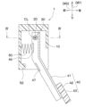
- FIG. 1 is a schematic configuration diagram of a brake-by-wire system including a side view of a brake pedal device according to a first embodiment.
- FIG. 2 is a plan view of the brake pedal device in the direction of arrow II in FIG. 1.
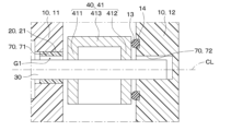
- FIG. 3 is a sectional view taken along line III-III in FIG. 2.
- FIG. 2 is a cross-sectional view showing a state in which the brake pedal is depressed to its maximum stroke in the brake pedal device according to the first embodiment.
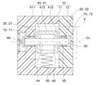
- FIG. 3A is a cross-sectional view taken along the line IV-IV in FIGS. 1, 2, and 3A.
- FIG. 5 is a cross-sectional view of the V section in FIG. 4 with the reaction force generation mechanism omitted.
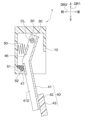
- FIG. 7 is a cross-sectional view showing a brake pedal in an initial position in a brake pedal device according to a second embodiment.
- FIG. 8A is a view taken along arrow A in FIG. 8A.
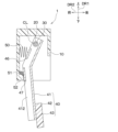
- FIG. 7 is a cross-sectional view showing a state in which a brake pedal and an elastic member are in contact with each other in a brake pedal device according to a second embodiment.
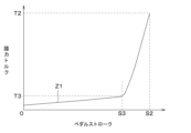
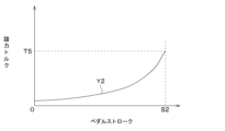
- FIG. 7 is a cross-sectional view showing a state in which the brake pedal is depressed to its maximum stroke in the brake pedal device according to the second embodiment. It is a graph showing the relationship between pedal stroke and pedal force torque in the brake pedal device according to the second embodiment. In the brake pedal device according to the second embodiment, it is a graph showing the relationship between the press-fitting allowance between the hole of the housing and the cylindrical member, and the fixing release torque.
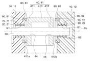
- FIG. 6 is a sectional view of a portion corresponding to FIG. 5 in a brake pedal device according to a third embodiment.
- FIG. 6 is a sectional view of a portion corresponding to FIG. 5 in a brake pedal device according to a fourth embodiment.
- FIG. 6 is a sectional view of a portion corresponding to FIG. 5 in a brake pedal device according to a sixth embodiment.
- FIG. 6 is a sectional view of a portion corresponding to FIG. 5 in a brake pedal device according to a sixth embodiment.
- FIG. 6 is a sectional view of a portion corresponding to FIG. 5 in a brake pedal device according to a seventh embodiment.
- FIG. 6 is a sectional view of a portion corresponding to FIG. 5 in a brake pedal device according to an eighth embodiment.
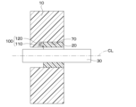
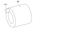
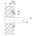
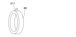
- FIG. 7 is a cross-sectional view showing a cylindrical member fixed to a hole of a housing in a brake pedal device according to a ninth embodiment. It is a perspective view of the cylinder member with which the brake pedal device concerning a 9th embodiment is provided.
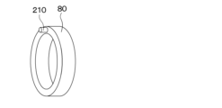
- FIG. 7 is a cross-sectional view showing a cylindrical member fixed to a hole of a housing in a brake pedal device according to a tenth embodiment. It is a perspective view of the cylinder member with which the brake pedal device concerning a 10th embodiment is provided.
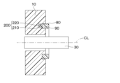
- FIG. 7 is a cross-sectional view showing a regulating member fixed to an annular groove of a housing in a brake pedal device according to an eleventh embodiment. It is a perspective view of the regulation member with which the brake pedal device concerning an 11th embodiment is provided.
- FIG. 7 is a cross-sectional view showing a regulating member fixed to an annular groove of a housing in a brake pedal device according to a twelfth embodiment. It is a perspective view of the regulation member with which the brake pedal device concerning a 12th embodiment is provided.
- FIG. 6 is a sectional view of a portion corresponding to FIG. 5 in a brake pedal device according to a thirteenth embodiment.
- the brake pedal device 1 of the first embodiment will be described by taking as an example one that is used in a brake-by-wire system 2 that is mounted on a vehicle and performs braking of the vehicle.
- the brake-by-wire system 2 is a system in which a brake mechanism 4 brakes the vehicle under drive control of an electronic control unit (hereinafter referred to as "ECU 3") mounted on the vehicle.
- ECU is an abbreviation for Electronic Control Unit.
- the brake pedal device 1 of the first embodiment is used in a complete brake-by-wire system 2.
- a complete brake-by-wire system 2 means that the components of the brake mechanism 4 and the brake pedal are not mechanically connected, and the ECU 3 drives the brake mechanism 4 based on the output signal of a sensor device included in the brake pedal device 1.
- This is a system that controls and brakes the vehicle.
- the component of the brake mechanism 4 is, for example, a master cylinder.
- the brake pedal device 1 includes a housing 10 as a fixed member, a cylindrical member 20, a shaft 30, a brake pedal 40, a reaction force generating mechanism 50, a sensor device 60, and the like.
- the housing 10 is directly fixed to the vehicle body with bolts (not shown) or indirectly fixed to the vehicle body via a base member (not shown). Specifically, the housing 10 is fixed to a dash panel or floor inside the vehicle. As shown in FIG. 4, the housing 10 includes a housing body 11 and a housing cover 12. The housing body 11 and the housing cover 12 are fixed to each other by, for example, screws, press fit, snap fit, etc. (not shown). A hole 70 is provided inside the housing 10 in which the cylindrical member 20 and the shaft 30 are placed. The holes 70 are provided in the housing body 11 and the housing cover 12, respectively. In the following description, the hole 70 provided in the housing body 11 may be referred to as a first hole 71, and the hole 70 provided in the housing cover 12 may be referred to as a second hole 72.
- the cylindrical member 20 is a sliding bearing and is provided between the inner wall of the hole 70 and the shaft 30.
- the cylindrical member 20 is also called a radial bearing that supports a load acting perpendicularly to the axis CL.
- the cylindrical member 20 may be made of metal, resin, ceramic, or the like, for example.
- the cylindrical member 20 provided inside the first hole 71 will be referred to as the first cylindrical member 21, and the cylindrical member 20 provided inside the second hole 72 will be referred to as the second cylindrical member 22.
- the first cylindrical member 21 will be referred to as the first cylindrical member 21
- the cylindrical member 20 provided inside the second hole 72 will be referred to as the second cylindrical member 22.
- the outer diameter of the cylindrical member 20 as a component is slightly larger than the inner diameter D2 of the hole 70. Therefore, the inner wall of the hole 70 and the radially outer outer wall of the cylindrical member 20 are fixed by press fitting.
- the inner diameter D3 of the cylindrical member 20 is larger than the outer diameter D4 of the shaft 30. Therefore, a predetermined gap G1 is provided between the radially inner inner wall of the cylindrical member 20 and the shaft 30, allowing the shaft 30 to rotate about its own axis with respect to the cylindrical member 20.
- the radially outer outer wall of the cylindrical member 20 will be simply referred to as the "outer wall of the cylindrical member 20," and the radially inner inner wall of the cylindrical member 20 will simply be referred to as the “inner wall of the cylindrical member 20.” There is.
- the shaft 30 is formed into a rod shape and is rotatably supported by the cylindrical member 20 inside the housing 10. Specifically, one end of the shaft 30 is rotatably supported by the first cylindrical member 21, and the other end of the shaft 30 is rotatably supported by the second cylindrical member 22. Therefore, the shaft 30 is supported inside the hole 70 via the cylindrical member 20, and the shaft 30 is supported in the circumferential direction of a circle centered on its own axis CL (hereinafter referred to as "around the axis") with respect to the housing 10. can be rotated within a predetermined angular range.
- the shaft 30 rotates while contacting a part of the inner wall of the cylindrical member 20 due to the driver's pedal force applied to the brake pedal 40 or gravity. 4 and 5, for convenience of explanation, the shaft 30 is in contact with a portion of the inner wall of the cylindrical member 20 on the lower side of the paper in each figure, and the shaft 30 is in contact with the portion of the inner wall of the cylindrical member 20 on the upper side of the paper in each figure. 30, there is a gap G1 between the two.
- the brake pedal 40 includes a pedal arm 41 and a pedal pad 42.
- the pedal arm 41 is fixed to the shaft 30 at one end in the longitudinal direction (i.e., the part disposed inside the housing 10), and the other end in the longitudinal direction (i.e., the part disposed outside the housing 10).
- a pedal pad 42 is provided at the position where the pedal is connected.
- the pedal arm 41 is formed by integrally forming a first side plate part 411, a second side plate part 412, and a top plate part 413.
- the first side plate portion 411 is a portion provided on the first cylindrical member 21 side.
- the second side plate portion 412 is a portion provided on the second cylinder member 22 side.
- the top plate part 413 is a part that connects the first side plate part 411 and the second side plate part 412.
- the first side plate part 411 and the second side plate part 412 are provided with insertion holes 44 and 45, respectively, through which the shaft 30 is inserted.
- the edges of the insertion holes 44 and 45 and the shaft 30 are fixed by, for example, welding. Therefore, the first side plate part 411 and the second side plate part 412 of the pedal arm 41 surround the radially outer region of the shaft 30 and are fixed to the shaft 30.
- the pedal pad 42 is provided at the other longitudinal end of the pedal arm 41, that is, at a portion located outside the housing 10.
- the tread surface 43 of the pedal pad 42 is a part that is stepped on by the driver's foot.
- the brake pedal 40 rotates in the forward and reverse directions within a predetermined angular range around the axis of the shaft 30 when the driver depresses the tread surface 43 of the pedal pad 42 .
- the tread surface 43 of the pedal pad 42 is an example of a predetermined position of the brake pedal 40 to which the driver can apply a depressing force.
- FIG. 3A shows an initial position within the operating range of the brake pedal 40 where no pedal force of the driver is applied to the brake pedal 40.
- FIG. 3A shows an initial position within the operating range of the brake pedal 40 where no pedal force of the driver is applied to the brake pedal 40.
- FIG. 3A shows an initial position within the operating range of the brake pedal 40 where no pedal force of the driver is applied to the brake pedal 40.
- FIG. 3A shows an
- a member 52 for regulating the maximum stroke position of the brake pedal 40 on the depression side is provided in the housing 10 and the like.
- the maximum stroke position of the brake pedal 40 is regulated by the contact between the member 52 and a portion 48 of the pedal arm 41. Note that what restricts the maximum stroke position on the depression side of the brake pedal 40 is not limited to the member 52 shown in FIG.
- the positions and shapes of the member 52 and the protrusions that regulate the maximum stroke position vary, and the material may be, for example, resin, metal, rubber, or a combination thereof.
- the brake pedal device 1 includes a member 52 that regulates the maximum stroke position of the brake pedal 40, and the position where the member 52 and the brake pedal 40 come into contact is defined as the maximum stroke position.
- the reaction force generating mechanism 50 is composed of, for example, a spring, an actuator, etc.
- the reaction force generating mechanism 50 is a mechanism that generates a reaction force against the driver's pedal force applied to the brake pedal 40.
- the brake pedal device 1 can eliminate the mechanical connection between the brake pedal 40 and the conventional master cylinder. It is possible to obtain a reaction force similar to that in which a force is obtained.
- the reaction force generating mechanism 50 is schematically shown as a spring that applies a reaction force to the reinforcing part 46, which has one end fixed to the housing 10 and the other end provided to the pedal arm 41.
- reaction force generating mechanism 50 is not limited to this, and various configurations can be adopted. Note that in FIG. 5, the reaction force generating mechanism 50 and the reinforcing section 46 are omitted. This also applies to drawings showing parts corresponding to FIG. 5 in the drawings referred to in each embodiment described later.
- the sensor device 60 detects the position (specifically, the rotation angle) of the shaft 30 or the brake pedal 40 with respect to the housing 10.
- Various types of sensors can be used as the sensor device 60.
- the sensor device 60 it is possible to employ a non-contact type sensor such as an inductive sensor, a magnetic sensor, or an optical sensor, or a contact type sensor such as a load sensor or a rotary encoder.
- the electrical signal output from the sensor device 60 is transmitted to the ECU 3.
- the ECU 3 is composed of a processor that performs control processing and arithmetic processing, a microcomputer including a storage section such as ROM and RAM that stores programs, data, etc., and its peripheral circuits.
- the storage unit is composed of a non-transitional tangible storage medium.
- the ECU 3 performs various control processes and calculation processes based on programs stored in the storage section, and controls the operation of each device connected to the output port. Specifically, the ECU 3 detects an accurate amount of pedal operation, that is, the amount of operation of the brake pedal 40, based on an electric signal transmitted from the sensor device 60, etc., and controls the drive of the brake mechanism 4.
- the number of ECUs 3 is not limited to one, and the driving of the brake mechanism 4 may be controlled by a plurality of ECUs 3.
- the brake mechanism 4 may be an electric brake that brakes each wheel by driving an electric motor in response to a command from the ECU 3 and pressing a brake pad against a disc brake rotor.
- the brake mechanism 4 may be configured to increase the hydraulic pressure of brake fluid by operating a master cylinder or a hydraulic pump, drive a wheel cylinder disposed on each wheel, and operate the brake pad. good.
- the brake mechanism 4 is also capable of performing normal control, ABS control, VSC control, etc. in response to control signals from the ECU 3.
- ABS stands for Anti-lock Braking System
- VSC Vehicle Stability Control.
- the cylindrical member 20 is provided between the shaft 30 and the inner wall of the hole 70 provided in the housing 10.
- the outer wall of the cylindrical member 20 and the inner wall of the hole 70 are fixed by press fitting.
- a predetermined gap G1 is provided between the inner wall of the cylindrical member 20 and the shaft 30.
- the size of the gap G1 between the inner wall of the cylindrical member 20 and the shaft 30 is such that even when the cylindrical member 20 and the shaft 30 expand and contract due to changes in environmental temperature, the gap G1 does not disappear and the inside of the cylindrical member 20
- the shaft 30 is set to be rotatable around the axis. Therefore, in this brake pedal device 1, the pedal force feeling when the driver depresses the brake pedal 40 does not change and remains constant regardless of changes in the environmental temperature.
- the foreign matter M1 is, for example, sand, dirt, or the like. If the cylindrical member 20 and the shaft 30 become stuck together due to the foreign object M1 being caught, and the shaft 30 stops rotating, the driver will be unable to depress and operate the brake pedal 40, which may impede the braking of the vehicle. There are concerns.
- the sticking between the cylindrical member 20 and the shaft 30 is not limited to the above-mentioned foreign object M1 being caught, but also due to a change in temperature due to, for example, the gap G1 between the inner wall of the cylindrical member 20 and the shaft 30 being unintentionally made small. It is also conceivable that the cylindrical member 20 and the shaft 30 are fixed to each other. As the temperature change, for example, contraction of the cylindrical member 20 at low temperatures can be considered. Alternatively, it is also possible that the cylindrical member 20 and the shaft 30 are stuck together due to rusting of the shaft 30 or the like.
- first configuration even if the cylindrical member 20 and the shaft 30 are stuck together, when the driver depresses the brake pedal 40, the hole in the housing 10 is removed before at least a part of the brake pedal device 1 is damaged.
- This configuration in which fixation between the inner wall of the portion 70 and the cylindrical member 20 is released.
- this configuration will be referred to as a "first configuration.”
- At least a portion of the brake pedal device 1 is damaged means that one or more of the housing 10, the shaft 30, the brake pedal 40, and their connection locations are damaged.
- damage includes destruction, deformation, displacement, etc., and refers to a problem in the function of a damaged member or a change in the shape of a damaged member.
- the torque when a typical driver depresses the brake pedal 40 with normal force is the torque that causes the brake pedal 40 to reach the maximum stroke position on the depressing side. corresponds to
- the torque that releases the fixation between the inner wall of the hole 70 and the cylindrical member 20 when a load is applied to the tread surface 43 of the pedal pad 42 while the cylindrical member 20 and the shaft 30 are fixed is defined as " It is called "unlocking torque”.
- the fixing release torque is set as follows in the first configuration and the second configuration, respectively.
- the fixing release torque is greater than 0, and when a load is applied to the tread surface 43 of the pedal pad 42 with the cylindrical member 20 and the shaft 30 fixed, the brake pedal The torque is set to be smaller than the torque that would damage at least a portion of the device 1.
- the unfixing torque being larger than 0 means that it is substantially larger than 0, and specifically, when the cylindrical member 20 and the shaft 30 are not fixed, the unfixing torque is greater than 0. This means that the frictional force is greater than the frictional force generated between the inner wall and the shaft 30.
- the state in which the cylindrical member 20 and the shaft 30 are not fixed together will be referred to as "the state in which the cylindrical member 20 and the shaft 30 are not fixed.”
- FIG. 6 shows the press-fitting distance between the inner wall of the hole 70 of the housing 10 and the outer wall of the cylindrical member 20 (hereinafter simply referred to as "press-fitting") on the horizontal axis, and the fixing release torque on the vertical axis.
- press-fitting the press-fitting distance between the inner wall of the hole 70 of the housing 10 and the outer wall of the cylindrical member 20 (hereinafter simply referred to as "press-fitting") on the horizontal axis, and the fixing release torque on the vertical axis.
- This figure shows the relationship between the fixing displacement and the fixing release torque.
- the solid line X1 in FIG. 6 as the press-fitting allowance increases, the fixing release torque also increases.
- the unfixing torque is larger than T1
- at least a portion of the brake pedal device 1 will be damaged when a load is applied to the tread surface 43 of the pedal pad 42 with the cylindrical member 20 and shaft 30 fixed together.
- the torque T1 can be determined through experiments or the like.
- the press-fitting allowance corresponding to the fixing release torque T1 is ⁇ 1. Therefore, when setting the fixing release torque in a range larger than 0 and smaller than the torque that would damage at least a part of the brake pedal device 1, the press-fitting allowance is set in a range larger than 0 and smaller than ⁇ 1.
- the range of press-fitting allowance in that case is indicated by a double-headed arrow A. In this way, by setting the range of the press-fitting allowance to the range indicated by the double-headed arrow A in FIG. 6, the above-mentioned first configuration can be realized.
- the fixing release torque is set to be larger than 0 and smaller than the pedal force torque at the maximum stroke position in normal times.
- the pedal force torque at the maximum stroke position in normal conditions refers to the brake pedal 40 when a load is applied to the tread surface 43 in a state where the cylindrical member 20 and the shaft 30 are not stuck together, etc. is the torque that reaches the maximum stroke position on the depressing side.
- FIG. 7 shows the relationship between the pedal stroke and the pedal force torque when the driver applies a load to the tread surface 43 of the pedal pad 42 with the cylindrical member 20 and shaft 30 not fixed together.
- the pedal force torque is the torque that is applied to the pedal pad 42 when the driver depresses the brake pedal 40, and specifically refers to the reaction force generated by the reaction force generation mechanism 50 and the axis of the shaft 30. It is the product of the distance from the center CL to the tread surface 43 of the pedal pad 42.
- the press-fitting allowance corresponding to the fixing release torque T2 is ⁇ 2. Therefore, when setting the fixing release torque in a range larger than 0 and smaller than the pedal force torque at the maximum stroke position in normal times, the press-fitting allowance is set in a range larger than 0 and smaller than ⁇ 2.
- the range of press-fitting allowance in that case is indicated by double-headed arrows B. In this way, by setting the range of the press-fitting allowance to the range shown by the double-headed arrow B in FIG. 6, the above-mentioned second configuration can be realized.
- the brake pedal device 1 of the first embodiment described above has the following configuration and the effects thereof.
- a predetermined gap G1 is provided between the inner wall of the cylindrical member 20 and the shaft 30. This makes it possible to maintain a constant pedal force feeling when the driver depresses the brake pedal 40, regardless of changes in the environmental temperature.
- the fixing release torque is applied to the brake pedal when a load is applied to the tread surface 43 of the pedal pad 42 in a state where the cylindrical member 20 and the shaft 30 are fixed.
- the torque is set to be smaller than the torque that would damage at least a portion of the device 1. According to this, even if the cylindrical member 20 and the shaft 30 are unintentionally stuck together due to, for example, a foreign object M1 being caught, when the driver depresses the brake pedal 40, the inner wall of the hole 70 of the housing 10 and the cylindrical member 20 is released, and the brake pedal 40 rotates. At this time, the fixation between the inner wall of the hole 70 of the housing 10 and the cylindrical member 20 is released and the brake pedal 40 rotates before at least a portion of the brake pedal device 1 is damaged.
- this brake pedal device 1 eliminates changes in pedal force feeling due to environmental temperature changes, and allows the brake pedal 40 to be depressed and operated even if the cylindrical member 20 and the shaft 30 are unintentionally stuck together. . Therefore, this brake pedal device 1 can improve the driver's feeling of pedal force and increase the safety of vehicle braking by the driver's operation of the brake pedal 40.
- the fixing release torque is set to be larger than 0 and smaller than the pedal force torque at the maximum stroke position in normal times.
- the pedal force torque at the maximum stroke position in normal times is generally the same as when a typical driver presses the brake pedal 40 with a normal force.
- the pedal force is set to a pedal force that can be applied to the pedal. Therefore, in the first embodiment, when the second configuration is adopted, the fixing release torque is set to be larger than 0 and smaller than the pedal force torque at the maximum stroke position in normal times.
- the inner wall of the hole 70 provided in the housing 10 and the cylindrical member 20 are fixed by press fitting. According to this, by setting the press fit margin between the inner wall of the hole 70 of the housing 10 and the outer wall of the cylindrical member 20, the hole 70 of the housing 10 and the cylindrical member 20 are normally in a fixed state; It is possible to realize a function in which the fixation is released by applying a predetermined torque. Therefore, the inner wall of the hole 70 of the housing 10 and the cylindrical member 20 can be easily fixed by press-fitting, so that the manufacturing assembly cost can be reduced.
- the brake pedal device 1 of the second embodiment has an elastic member 51 provided at a position where it can come into contact with the brake pedal 40 when the driver depresses the brake pedal 40. It is equipped with The elastic member 51 operates within the operating range of the brake pedal 40, from a position halfway between the initial position where the driver's pedal force is not applied to the brake pedal 40 and the maximum stroke position on the depression side to the maximum stroke position on the depression side. It is set up over .
- the elastic member 51 is made of rubber, for example, and is fixed to the housing 10. Note that the arrangement relationship, shape, etc. of the member 52 that regulates the maximum stroke position of the brake pedal 40 and the elastic member 51 are not limited to those shown in the drawings, and can be arbitrarily set.
- the pedal arm 41 has a pressing portion 47 at a position corresponding to the elastic member 51.
- the pressing portion 47 may be configured integrally with the first side plate portion 411 and the second side plate portion 412 of the pedal arm 41, or may be configured as a separate member.
- the reinforcing portion 46 provided at a position corresponding to the reaction force generating mechanism 50 on the pedal arm 41 and the pressing portion 47 may be integrally configured.
- the pedal arm 41 will be described as having a pressing portion 47 in a part thereof.
- the brake pedal device 1 includes a member 52 that regulates the maximum stroke position of the brake pedal 40, and the position where the member 52 and the brake pedal 40 come into contact is defined as the maximum stroke position.
- FIG. 11 shows the relationship between the pedal stroke and the pedal force torque when the driver applies a load to the tread surface 43 of the pedal pad 42 with the cylindrical member 20 and shaft 30 not fixed together.
- the brake pedal 40 and the elastic member 51 are not in contact during the pedal stroke from 0 to S3.
- the pedal stroke is S3
- the brake pedal 40 and the elastic member 51 come into contact.
- the pedal stroke is S2
- the brake pedal 40 is at its maximum stroke position.
- the pedal force torque increases as the reaction force generated by the reaction force generation mechanism 50 increases.
- the pedal force torque when the pedal stroke is S3, that is, when the brake pedal 40 contacts the elastic member 51 is T3.
- the torque at which the brake pedal 40 reaches the position where it contacts the elastic member 51 when a load is applied to the tread surface 43 of the pedal pad 42 with the cylindrical member 20 and the shaft 30 in a non-adhesive state is described. is said as follows. That is, this torque is referred to as "the pedal force torque at the position where the brake pedal 40 contacts the elastic member 51 under normal conditions.”
- the brake pedal device 1 of the second embodiment can adopt a third configuration described below.
- the third configuration is a configuration in which the brake pedal device 1 includes the above-mentioned elastic member 51, and further includes the following configuration. That is, in the third configuration, in a configuration including the elastic member 51, when a typical driver depresses the brake pedal 40 with normal force while the cylindrical member 20 and the shaft 30 are fixed, the hole in the housing 10 This is a configuration in which fixation between the inner wall of the portion 70 and the cylindrical member 20 is released.
- the torque when a typical driver depresses the brake pedal 40 with a normal force means that the torque generated when the brake pedal 40 is depressed when a load is applied to the tread surface 43 under normal conditions. This corresponds to the torque at which the elastic member 40 and the elastic member 51 come into contact.
- the torque (that is, the unfixing torque) is set as follows in the third configuration described above.
- the brake pedal device 1 sets the fixing release torque to be larger than 0 and smaller than the pedal force torque at the position where the brake pedal 40 contacts the elastic member 51 in normal times. .
- the press-fitting allowance corresponding to the fixing release torque T3 is ⁇ 3. Therefore, when setting the fixing release torque in a range larger than 0 and smaller than the pedal force torque at the position where the brake pedal 40 contacts the elastic member 51 under normal conditions, the press-fitting margin is larger than 0 and smaller than ⁇ 3. Keep it in a small range.
- the range of the press-fitting allowance in that case is indicated by a double-headed arrow C. In this way, by setting the range of the press-fitting allowance to the range shown by the double-headed arrow C in FIG. 12, the third configuration described above can be realized.
- the brake pedal device 1 adopts the first configuration
- the locking release torque is larger than 0, and when a load is applied to the tread surface 43 in a state where the cylindrical member 20 and the shaft 30 are fixed, the brake pedal The torque is set to be lower than the torque that would damage at least a portion of the device 1.
- the above-mentioned first configuration can be realized by setting the range of the press-fitting allowance to the range shown by the double-headed arrow A in FIG. 12.
- the brake pedal device 1 sets the fixing release torque to be larger than 0 and smaller than the pedal force torque at the maximum stroke position in normal times. In that case, by setting the range of the press-fitting allowance to the range shown by the double-headed arrow B in FIG. 12, the above-mentioned second configuration can be realized.
- the brake pedal device 1 of the second embodiment described above has the following configuration and the effects thereof in addition to the effects described in the first embodiment.
- the brake pedal device 1 of the second embodiment includes an elastic member 51 that is provided over the operating range of the brake pedal 40 from a position midway between the initial position and the maximum stroke position to the maximum stroke position.
- the fixing release torque is set to be larger than 0 and smaller than the pedal force torque at the position where the brake pedal 40 contacts the elastic member 51 in normal times. do.
- the brake pedal device 1 may include the elastic member 51 that comes into contact with the brake pedal 40 in the latter half of the pedal stroke in order to improve the feeling of pedal force.
- the torque required for the brake pedal 40 to reach the maximum stroke position from the position where it contacts the elastic member 51 is set to be very large.
- the driver is a weak driver, it may be difficult to depress the brake pedal 40 until it reaches the maximum stroke position.
- the torque required to reach the position where the brake pedal 40 comes into contact with the elastic member 51 is the same as that of a typical driver.
- the pedal force that can be applied to the brake pedal 40 is set to a value that can be applied to the brake pedal 40. Note that by pressing the brake pedal 40 to a position where it contacts the elastic member 51, it is possible to sufficiently decelerate the vehicle.
- a third embodiment will be described.
- the third embodiment differs from the first embodiment etc. because a part of the configuration of the cylindrical member 20 is changed from the first embodiment etc., and other aspects are the same as the first embodiment etc. Only parts will be explained.
- the brake pedal device 1 of the third embodiment includes a seal member 13 between the second side plate portion 412 of the brake pedal 40 and the housing cover 12.
- the seal member 13 corresponds to an example of a foreign matter prevention structure that prevents foreign matter M1 from entering the second hole 72 provided in the housing cover 12.
- the seal member 13 is provided so as to surround a radially outer region of the shaft 30. Further, the sealing member 13 is formed of, for example, an O-ring, and is fitted into a groove 14 provided in the housing cover 12. Note that the sealing member 13 is not limited to an O-ring, but may also be configured such that, for example, a spring (not shown) and a sealing material such as resin are arranged in the groove 14, and the sealing material is brought into close contact with the brake pedal 40 by the spring. . With such a configuration, even if the brake pedal 40 and the shaft 30 are misaligned in the axial direction, the seal member 13 itself elastically deforms to tightly contact the second side plate portion 412 and close the second hole. It is possible to prevent foreign matter M1 from entering the portion 72.
- the brake pedal device 1 of the third embodiment includes the first cylindrical member 21 inside the first hole 71 provided in the housing body 11, and the second hole 72 provided in the housing cover 12. is not provided with the second cylindrical member 22. Therefore, the portion of the shaft 30 on the second hole 72 side is rotatably supported by the inner wall of the second hole 72.
- the brake pedal device 1 of the third embodiment described above includes a seal member 13 as a foreign matter prevention structure between the second side plate portion 412 of the brake pedal 40 and the housing cover 12. This prevents foreign matter M1 from entering the second hole 72 provided in the housing cover 12. Therefore, the brake pedal device 1 of the third embodiment does not include the second cylindrical member 22 in the second hole 72 of the housing cover 12. In this way, the brake pedal device 1 can insert the cylinder member 20 into the first hole 71 or the second hole 72 provided in the housing 10 if the structure is such that foreign matter M1 does not enter there. There is no need to prepare.
- the brake pedal device 1 includes a foreign matter prevention structure between the first side plate portion 411 of the brake pedal 40 and the housing body 11 to prevent foreign matter M1 from entering the first hole portion 71. If this is prevented, there is no need to provide the first cylindrical member 21 in the first hole 71. In this way, the brake pedal device 1 of the third embodiment can have a simple configuration.
- the fourth embodiment differs from the first embodiment in that a part of the configuration of the brake pedal device 1 is changed, and the rest is the same as the first embodiment, so the differences from the first embodiment are as follows. I will only explain. Note that the brake pedal device 1 of the fourth embodiment does not include the elastic member 51 described in the second embodiment.
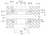
- the brake pedal device 1 of the fourth embodiment does not include the cylindrical member 20 described in the first embodiment etc., but instead includes a regulating member 80.
- the regulating member 80 is provided between the first side wall portion 411 of the brake pedal 40 and the housing body 11, and between the second side wall portion of the brake pedal 40 and the housing cover 12.
- the regulating member 80 is also called a thrust bearing that supports a load acting in the direction in which the shaft center CL extends (that is, in the axial direction).
- the regulating member 80 may be made of metal, resin, ceramic, or the like, for example.
- the regulating member 80 provided on the housing body 11 may be referred to as a first regulating member 81
- the regulating member 80 provided on the housing cover 12 may be referred to as a second regulating member 82.
- Both the first regulating member 81 and the second regulating member 82 are formed in an annular shape and are provided so as to surround a radially outer region of the shaft 30.
- the first regulating member 81 and the second regulating member 82 regulate the movement range of the shaft 30 and the brake pedal 40 in the axial direction.
- a first annular groove 91 into which the first regulating member 81 is fitted is provided on the surface of the housing body 11 facing the first side plate portion 411.
- the first annular groove 91 is provided so as to surround a radially outer region of the shaft 30.
- the first regulating member 81 is fixed to the first annular groove 91 by press fitting.
- a second annular groove 92 into which the second regulating member 82 is fitted is provided on the surface of the housing cover 12 facing the second side plate portion 412 .
- the second annular groove 92 is provided so as to surround a radially outer region of the shaft 30.
- the second regulating member 82 is fixed to the second annular groove 92 by press fitting.
- the first annular groove 91 and the second annular groove 92 may be collectively referred to as an annular groove 90.
- the surface of the regulating member 80 facing radially inward and the surface facing radially outward of the annular groove 90 of the housing 10 are press-fitted.
- restriction member 80 and the annular groove 90 may be press-fitted in such a manner that the surface of the restriction member 80 facing radially outward and the surface of the annular groove 90 of the housing 10 facing radially inward are press-fitted. is also possible. This also applies to FIGS. 19, 20, 21, 26, 28, and 30, which will be referred to in each embodiment described later.
- the distance D6 between the first regulating member 81 and the second regulating member 82 is larger than the outer width D5 of the brake pedal 40 in the axial direction.
- the outer width D5 in the axial direction of the brake pedal 40 is the distance between a surface 411a of the first side plate 411 facing the housing body 11 and a surface 412a of the second side plate 412 facing the housing cover 12.
- a predetermined gap is provided between the surfaces 411a, 412a of the brake pedal 40 facing in the axial direction and the regulating member 80, allowing the brake pedal 40 and the shaft 30 to rotate around the axis with respect to the regulating member 80.
- G2 is provided. Specifically, in FIG.
- the brake pedal 40 and the shaft 30 are located between the surface 412a of the second side plate portion 412 facing the housing cover 12 and the second regulating member 82 around the axis of the regulating member 80.
- a predetermined gap G2 is provided which is rotatable.
- a predetermined gap is provided between the surface 411a of the first side plate portion 411 facing the housing body 11 and the first regulating member 81, in which the brake pedal 40 and the shaft 30 can rotate around the axis with respect to the regulating member 80.
- G2 may be provided.
- the brake pedal 40 is movable in the axial direction between the first regulating member 81 and the second regulating member 82 . In FIG.
- the first side plate part 411 of the brake pedal 40 and the first regulating member 81 are in contact, and a gap G2 is created between the second side plate part 412 of the brake pedal 40 and the second regulating member 82. It shows an open state.
- the distance D6 between the first regulating member 81 and the second regulating member 82 is such that even when the regulating member 80, the housing 10, the brake pedal 40, etc. expand and contract due to changes in environmental temperature, the axis of the brake pedal 40 It is set to maintain a state larger than the outer width D5 in the center direction. Therefore, even if the regulation member 80, the housing 10, the brake pedal 40, etc. expand and contract due to changes in the environmental temperature, the gap G2 between the first side plate portion 411 of the brake pedal 40 and the first regulation member 81 will not disappear. . Alternatively, even if the regulation member 80, the housing 10, the brake pedal 40, etc.
- the sticking of the brake pedal 40 and the regulating member 80 is not limited to the above-mentioned foreign object M2 being caught, but also caused by, for example, the gap G2 between the brake pedal 40 and the regulating member 80 being unintentionally made small and due to temperature changes. It is also conceivable that the brake pedal 40 and the regulating member 80 are stuck together. Alternatively, it is also possible that the brake pedal 40 and the regulating member 80 become stuck together due to the brake pedal 40 becoming rusty or the like.
- the fourth embodiment even if the brake pedal 40 and the regulating member 80 are stuck together, when the driver depresses the brake pedal 40, the annular groove 90 is removed before at least a part of the brake pedal device 1 is damaged.
- the structure is such that the fixation between the inner wall of the regulating member 80 and the regulating member 80 is released.
- this configuration will be referred to as a "fourth configuration.”
- the fourth embodiment when a typical driver depresses the brake pedal 40 with normal force in a state where the brake pedal 40 and the regulation member 80 are fixed, the inner wall of the annular groove 90 of the housing 10 and the regulation member 80 are pressed together. It is also possible to have a configuration in which the fixation with the member 80 is released. Hereinafter, this configuration will be referred to as the "fifth configuration.” Note that in the case where the brake pedal device 1 does not include the elastic member 51 as in the first embodiment, the torque when a typical driver depresses the brake pedal 40 with normal force is the torque when the brake pedal 40 is depressed. Corresponds to the torque to reach the maximum stroke position on the depressing side.
- the fixation between the inner wall of the annular groove 90 and the regulating member 80 is released.
- the torque for each of the fourth and fifth configurations is set as follows. In the following explanation, the torque that releases the fixation between the inner wall of the annular groove 90 and the regulating member 80 when a load is applied to the tread surface 43 of the pedal pad 42 with the regulating member 80 and the shaft 30 fixed together will be described. , referred to as the "thrust unfixing torque.”
- the thrust release torque is set to be greater than 0, and when a load is applied to the tread surface 43 with the brake pedal 40 and the regulating member 80 fixed, at least one of the brake pedal devices 1 Set the torque to be lower than the one that will cause damage to some parts.
- the thrust lock release torque being larger than 0 means that it is substantially larger than 0, and specifically, when the brake pedal 40 and the regulating member 80 are not fixed, This means that the frictional force is greater than the frictional force generated between the regulating member 80 and the regulating member 80 .
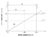
- FIG. 15 shows the relationship between the regulating member press-fitting allowance and the thrust fixing release torque, with the horizontal axis representing the regulating member press-fitting allowance and the vertical axis representing the thrust fixing release torque.
- the restriction member press-fitting allowance is the press-fitting allowance between the inner wall of the annular groove 90 of the housing 10 and the outer wall of the restricting member 80. As shown by the solid line X3 in FIG. 15, as the restriction member press-fit allowance increases, the thrust release torque also increases.
- the restriction member press-fitting allowance corresponding to the thrust release torque T4 is ⁇ 4. Therefore, when setting the thrust release torque to a range larger than 0 and smaller than the torque that would damage at least a part of the brake pedal device 1, the restriction member press-fitting allowance should be set to a range larger than 0 and smaller than ⁇ 4. shall be.
- the range of the press-fitting allowance for the regulating member in this case is indicated by a double-headed arrow D. In this way, by setting the range of the press-fitting allowance of the regulating member to the range indicated by the double-headed arrow D in FIG. 15, the fourth configuration described above can be realized.
- the brake pedal device 1 sets the thrust release torque to be larger than 0 and smaller than the pedal force torque at the maximum stroke position in normal times.
- “depression force torque at the maximum stroke position in normal conditions” refers to the state in which the brake pedal 40 is on the depressing side when the brake pedal 40 and the regulating member 80 are not fixed and a load is applied to the tread surface 43. The torque that reaches the maximum stroke position.
- FIG. 16 shows the relationship between the pedal stroke and the pedal force torque when the driver applies a load to the tread surface 43 of the pedal pad 42 when the brake pedal 40 and the regulating member 80 are not fixed together.
- the pedal force torque is the torque that is applied to the pedal pad 42 when the driver depresses the brake pedal 40, and specifically refers to the reaction force generated by the reaction force generation mechanism 50 and the axis of the shaft 30. It is the product of the distance from the center CL to the tread surface 43 of the pedal pad 42.
- the restriction member press-fitting allowance corresponding to the thrust release torque T5 is ⁇ 5. Therefore, when the thrust fixing release torque is set in a range larger than 0 and smaller than the pedal force torque at the maximum stroke position in normal times, the restriction member press-fitting allowance is set in a range larger than 0 and smaller than ⁇ 5.
- the range of the press-fitting allowance for the regulating member in this case is indicated by a double-headed arrow E. In this way, by setting the range of the press-fitting allowance of the regulating member to the range shown by the double-headed arrow E in FIG. 15, the fifth configuration described above can be realized.
- the brake pedal device 1 of the fourth embodiment described above has the following configuration and its effects.
- a predetermined gap G2 is provided between the regulating member 80 provided in the housing 10 and the surfaces 411a and 412a of the brake pedal 40 facing in the axial direction. There is. This makes it possible to maintain a constant pedal force feeling when the driver depresses the brake pedal 40, regardless of changes in the environmental temperature.
- the thrust release torque is determined by the brake pedal device 1 when a load is applied to the tread surface 43 with the brake pedal 40 and the regulating member 80 fixed together. At least a portion of the torque is set to be smaller than the torque that causes damage.
- this brake pedal device 1 eliminates changes in pedal force feeling due to environmental temperature changes, and allows the brake pedal 40 to be depressed and operated even if the brake pedal 40 and the regulating member 80 are unintentionally stuck together. be. Therefore, this brake pedal device 1 can improve the driver's feeling of pedal force and increase the safety of vehicle braking by the driver's operation of the brake pedal 40.
- the thrust lock release torque is set to be larger than 0 and smaller than the pedal force torque at the maximum stroke position in normal times.
- the pedal force torque at the maximum stroke position in normal times is such that a typical driver presses the brake pedal 40 with a normal force.
- the pedal force is set to a pedal force that can be applied to the pedal.
- the inner wall of the annular groove 90 provided in the housing 10 and the regulating member 80 are fixed by press fitting. According to this, by setting the press fit margin between the inner wall of the annular groove 90 of the housing 10 and the outer wall of the regulating member 80, the annular groove 90 of the housing 10 and the regulating member 80 are normally in a fixed state; It is possible to realize a function in which the fixation is released by applying a predetermined torque. Therefore, the inner wall of the annular groove 90 of the housing 10 and the regulating member 80 can be easily fixed by press-fitting, thereby reducing manufacturing assembly costs.
- the fifth embodiment differs from the fourth embodiment in that a part of the configuration of the brake pedal device 1 is changed, and the rest is the same as the fourth embodiment, so the differences from the fourth embodiment are as follows. I will only explain. Note that the brake pedal device 1 of the fifth embodiment includes the elastic member 51 described in the second embodiment.
- FIG. 17 shows the relationship between the pedal stroke and the pedal force torque when the driver applies a load to the tread surface 43 of the pedal pad 42 when the brake pedal 40 and the regulating member 80 are not fixed to each other.
- the pedal force torque increases as the reaction force generated by the reaction force generation mechanism 50 increases.
- the pedal force torque when the pedal stroke is S3, that is, when the brake pedal 40 contacts the elastic member 51 is T6.
- Torque is referred to as: That is, this torque is referred to as "the pedal force torque at the position where the brake pedal 40 contacts the elastic member 51 under normal conditions.”
- the brake pedal device 1 of the fifth embodiment can adopt a sixth configuration described below.
- the sixth configuration is a configuration in which the brake pedal device 1 includes the above-mentioned elastic member 51, and further includes the following configuration.
- the sixth configuration is a configuration including the elastic member 51, and when a typical driver depresses the brake pedal 40 with normal force while the brake pedal 40 and the regulating member 80 are firmly attached, the annular shape of the housing 10 This is a configuration in which fixation between the inner wall of the groove 90 and the regulating member 80 is released.
- the torque when a typical driver depresses the brake pedal 40 with a normal force means that the torque generated when the brake pedal 40 is depressed when a load is applied to the tread surface 43 under normal conditions. This corresponds to the torque at which the elastic member 40 and the elastic member 51 come into contact.
- a torque ( That is, the thrust unfixing torque) is set as follows in the above-mentioned sixth configuration.
- the brake pedal device 1 sets the thrust release torque to be larger than 0 and smaller than the pedal force torque at the position where the brake pedal 40 contacts the elastic member 51 in normal times. do.
- the press-fitting amount of the regulating member corresponding to the thrust release torque T6 is ⁇ 6. Therefore, when setting the thrust release torque to be larger than 0 and smaller than the pedal force torque at the position where the brake pedal 40 contacts the elastic member 51 under normal conditions, the restriction member press-fit allowance is larger than 0 and , ⁇ 6.
- the range of the press-fitting allowance for the regulating member in this case is indicated by a double-headed arrow F. In this way, by setting the range of the press-fitting allowance of the regulating member to the range indicated by the double-headed arrow F in FIG. 18, the above-mentioned sixth configuration can be realized.
- the fourth configuration described above can be realized by setting the range of the press-fitting allowance of the regulating member to the range shown by the double-headed arrow D in FIG.
- the brake pedal device 1 sets the thrust unfixing torque to be larger than 0 and smaller than the pedal force torque at the maximum stroke position in normal times.
- the fifth configuration described above can be realized by setting the range of the press-fitting allowance of the regulating member to the range shown by the double-headed arrow E in FIG.
- the brake pedal device 1 of the fifth embodiment described above has the following configuration and the effects thereof in addition to the effects described in the fourth embodiment.
- the brake pedal device 1 of the fifth embodiment includes an elastic member 51 that is provided over the operating range of the brake pedal 40 from a position midway between the initial position and the maximum stroke position to the maximum stroke position.
- the thrust release torque is larger than 0 and smaller than the pedal force torque at the position where the brake pedal 40 contacts the elastic member 51 in normal times.
- the brake pedal device 1 may include the elastic member 51 that comes into contact with the brake pedal 40 in the latter half of the pedal stroke in order to improve the feeling of pedal force.
- the torque required for the brake pedal 40 to reach the maximum stroke position from the position where it contacts the elastic member 51 is set to be very large.
- the driver is a weak driver, it may be difficult to depress the brake pedal 40 until it reaches the maximum stroke position.
- the torque that the brake pedal 40 reaches the position where it contacts the elastic member 51 is not the same as that of a typical driver.
- the pedal force is set to a force that can be applied to the brake pedal 40. Note that by pressing the brake pedal 40 to a position where it contacts the elastic member 51, it is possible to sufficiently decelerate the vehicle.
- the sixth embodiment differs from the fourth and fifth embodiments in that a part of the configuration of the regulating member 80 is changed, and is otherwise the same as the fourth and fifth embodiments. Only the parts different from the fifth embodiment will be explained.
- the brake pedal device 1 of the sixth embodiment includes a seal member 13 between the second side plate portion 412 of the brake pedal 40 and the housing cover 12.
- the seal member 13 corresponds to an example of a foreign matter prevention structure that prevents foreign matter M2 from entering the second hole 72 provided in the housing cover 12.
- the seal member 13 is provided so as to surround a radially outer region of the shaft 30. Further, the sealing member 13 is formed of, for example, an O-ring, and is fitted into a groove 14 provided in the housing cover 12. Even if the brake pedal 40 and the shaft 30 are misaligned in the axial direction, the seal member 13 is elastically deformed and comes into close contact with the second side plate portion 412, and foreign matter is trapped in the second hole portion 72. It is possible to prevent M2 from invading.
- the brake pedal device 1 of the sixth embodiment includes a first regulating member 81 between the housing body 11 and the first side plate portion 411, and a first regulating member 81 between the housing cover 12 and the second side plate portion 412. 2 restriction member 82 is not provided.
- the brake pedal device 1 of the sixth embodiment described above includes a seal member 13 as a foreign matter prevention structure between the second side plate portion 412 of the brake pedal 40 and the housing cover 12. This prevents foreign matter M2 from entering between the second side plate portion 412 and the housing cover 12. Therefore, the brake pedal device 1 of the sixth embodiment does not include the second regulating member 82 between the second side plate portion 412 and the housing cover 12. In this way, the brake pedal device 1 does not need to include the first regulating member 81 or the second regulating member 82 if the structure prevents foreign matter M2 from entering between the housing 10 and the brake pedal 40.
- the brake pedal device 1 includes a foreign matter prevention structure between the first side plate portion 411 of the brake pedal 40 and the housing body 11, which prevents foreign matter M2 from entering from there. If so, it is not necessary to provide the first regulating member 81. In this way, the brake pedal device 1 of the sixth embodiment can have a simple configuration.
- the seventh embodiment differs from the fourth and fifth embodiments in that a part of the configuration of the regulating member 80 is changed, and the rest is the same as the fourth and fifth embodiments. Only the parts different from the fifth embodiment will be explained.
- the brake pedal device 1 of the seventh embodiment includes a first regulating member 81 provided on the surface of the housing body 11 facing the brake pedal 40. Further, the brake pedal device 1 of the seventh embodiment includes a third regulating member 83 provided on the surface of the housing body 11 facing away from the brake pedal 40. The brake pedal device 1 of the seventh embodiment does not include the second regulating member 82 described in the fourth and fifth embodiments.
- the third regulating member 83 is formed in an annular shape and is provided so as to surround the radially outer region of the shaft 30.
- the third regulating member 83 is capable of sliding contact with the rotating body 31 provided on the shaft 30. Therefore, it can also be said that the third regulating member 83 is provided on the surface of the housing body 11 that faces the rotating body 31.
- the rotating body 31 can be used, for example, as a sensor component that constitutes a part of the sensor device 60. Specifically, when an inductive sensor is employed as the sensor device 60, the rotating body 31 may be used as a target. Further, when a magnetic sensor is employed as the sensor device 60, the rotating body 31 may be used as a magnetic circuit section.
- a third annular groove 93 into which the third regulating member 83 is fitted is provided on the surface of the housing body 11 facing the rotating body 31.
- the third annular groove 93 is provided so as to surround a radially outer region of the shaft 30.
- the third regulating member 83 is fixed to the inner wall of the third annular groove 93 by press fitting.
- the movement range of the shaft 30 and the brake pedal 40 in the axial direction is regulated by a first regulating member 81 and a third regulating member 83.
- the distance D7 between the surface of the first regulating member 81 facing the brake pedal 40 side and the surface of the third regulating member 83 facing the rotating body 31 is greater than the distance D8 in the axial direction between the brake pedal 40 and the rotating body 31. It's also big. Therefore, a predetermined gap G2 is provided between the brake pedal 40 and the surface of the first regulating member 81 that faces the brake pedal 40, allowing the brake pedal 40 and the shaft 30 to rotate around the axis with respect to the regulating member 80. is provided. Alternatively, a predetermined gap G2 is provided between the surface of the third regulating member 83 facing the rotating body 31 and the rotating body 31, allowing the brake pedal 40 and the shaft 30 to rotate around the axis with respect to the regulating member 80. It is provided. Therefore, the brake pedal 40 is movable in the axial direction within the predetermined gap G2.
- FIG. 20 shows a state in which the third regulating member 83 and the rotating body 31 are in contact and a gap G2 is created between the first side plate portion 411 of the brake pedal 40 and the first regulating member 81. .
- the gap G2 is set so as not to disappear even when the regulating member 80, the housing 10, the brake pedal 40, etc. expand and contract due to changes in the environmental temperature. Therefore, in this brake pedal device 1, the pedal force feeling when the driver depresses the brake pedal 40 does not change and remains constant regardless of changes in the environmental temperature.
- the gap G2 between the first regulating member 81 and the brake pedal 40 or between the third regulating member 83 and the rotating body 31, there is a problem that the gap G2 shown in the broken line arrow in FIG. As such, there is a risk that foreign matter M2 may enter the gap G2.
- the foreign matter M2 is, for example, sand, dirt, or the like. If the first regulating member 81 and the brake pedal 40 or the third regulating member 83 and the rotary body 31 become stuck and do not rotate due to the foreign object M2 being caught, the driver cannot press and operate the brake pedal 40. There are concerns that this may cause problems with vehicle braking.
- the brake pedal device 1 of the seventh embodiment when the driver depresses the brake pedal 40, a predetermined torque is applied to the inner wall of the annular groove 90 of the housing 10.
- the structure is such that the fixation between the regulating member 80 and the regulating member 80 is released.
- fixing the inner wall of the first annular groove 91 of the housing body 11 and the first regulating member 81, and fixing the inner wall of the third annular groove 93 of the housing body 11 and the third regulating member 83. is configured to be released by the predetermined torque described in the fourth and fifth embodiments. Therefore, the brake pedal device 1 of the seventh embodiment can also achieve the same effects as the fourth to sixth embodiments.
- the eighth embodiment differs from the fourth and fifth embodiments in that the configuration of the brake pedal 40 is changed, and other aspects are the same as in the fourth and fifth embodiments. Only the parts that differ from the form will be explained.
- a pedal arm 41 of a brake pedal 40 has a first side plate portion 411 and a second side plate portion 412 at least at a portion connected to the shaft 30. and does not have a top plate portion 413. Even in such a configuration, the movement range of the shaft 30 and the brake pedal 40 in the axial direction is restricted by the first restriction member 81 and the second restriction member 82. Therefore, the brake pedal device 1 of the eighth embodiment can also have the same effects as the fourth and fifth embodiments.
- the ninth embodiment differs from the first to third embodiments in that the method of fixing the cylindrical member 20 and the housing 10 is changed, and other aspects are the same as the first to third embodiments. Only the parts that are different from the first to third embodiments will be explained.
- the cylindrical member 20 included in the brake pedal device 1 of the ninth embodiment is fixed to the hole 70 provided in the housing 10 by a rotation restricting portion 100.
- the rotation restricting portion 100 restricts rotation of the cylindrical member 20 with respect to the inner wall of the hole portion 70.
- the rotation regulating portion 100 includes a convex portion 110 protruding from a part of the surface of the cylindrical member 20 facing in the axial direction, and a concave portion 120 provided in the hole 70 of the housing 10. It is made up of.
- the protrusion 110 provided on the cylindrical member 20 is configured to fit into a recess 120 provided in the hole 70 of the housing 10 . Thereby, rotation of the cylindrical member 20 with respect to the inner wall of the hole 70 of the housing 10 is restricted, and the inner wall of the hole 70 and the cylindrical member 20 are fixed.
- the rotation regulating part 100 when the cylindrical member 20 and the shaft 30 are unintentionally stuck together, when a predetermined load is applied to the tread surface 43 of the pedal pad 42, the rotation regulating part 100 is damaged and the hole part 70 of the housing 10 is damaged.
- the fixation between the inner wall and the cylindrical member 20 is released.
- at least one of the convex portion 110 and the concave portion 120 constituting the rotation regulating portion 100 is damaged when a predetermined load is applied to the tread surface 43 while the cylindrical member 20 and the shaft 30 are fixed, and a hole is formed. It is configured to release the fixation between the inner wall of the portion 70 and the cylindrical member 20.
- damage includes destruction, deformation, displacement, etc., and refers to a problem in the function of a damaged member or a change in the shape of a damaged member.
- the pedaling force torque i.e., fixation release torque
- the rotation regulating portion 100 is not damaged by the same unfixing torque as the unfixing torque set when the first configuration, second configuration, and third configuration are adopted. is set to Specifically, the material, shape, size, etc. of at least one of the convex portion 110 and the concave portion 120 that constitute the rotation regulating portion 100 are adjusted.
- the brake pedal device 1 of the ninth embodiment described above has the following configuration and the effects thereof.
- the brake pedal device 1 according to the ninth embodiment has a rotation regulating portion provided on at least one of the inner wall of the hole 70 of the housing 10 and the outer wall of the cylindrical member 20 for regulating rotation of the cylindrical member 20 with respect to the inner wall of the hole 70. 100.
- the rotation regulating portion 100 is damaged when a predetermined load is applied to the tread surface 43 of the pedal pad 42 while the cylindrical member 20 and the shaft 30 are fixed, and the inner wall of the hole 70 and the cylindrical member 20 are not fixed. It is configured to be released.
- the press-fitting tension force changes depending on the change in the environmental temperature.
- the unlocking torque may vary. That is, the unfixing torque may become large at low temperatures or high temperatures.
- the inner wall of the hole 70 of the housing 10 and the cylindrical member 20 are fixed by the rotation regulating part 100, and when a predetermined fixing release torque is applied, the rotation regulating part 100 releases the fixing. is configured to release the . According to this, it becomes possible to set the fixing release torque to be relatively small regardless of changes in the environmental temperature.
- this brake pedal device 1 even if the cylindrical member 20 and the shaft 30 are unintentionally stuck together, the driver can damage the rotation regulating portion 100 with a relatively small pedal force, and the inner wall of the hole 70 and the cylindrical member 20 can be damaged.
- the brake pedal 40 can be released and operated by depressing the brake pedal 40.
- the rotation regulating portion 100 includes a recess 120 provided in the inner wall of the hole 70 of the housing 10 and a convex portion 110 that protrudes from the outer wall of the cylindrical member 20 and fits into the recess 120. have. At least one of the concave portion 120 and the convex portion 110 is damaged when a predetermined load is applied to the tread surface 43 of the pedal pad 42 while the cylindrical member 20 and the shaft 30 are fixed, and the inner wall of the hole 70 and the cylindrical member 20 are damaged. It is configured to release the fixation. According to this, it is possible to realize the rotation regulating section 100 with a simple configuration.
- the rotation regulating section 100 As an example of the rotation regulating section 100, a recess 120 provided in the inner wall of the hole 70 of the housing 10 and a recess 120 that protrudes from the outer wall facing the axial direction of the cylindrical member 20 and fit into the recess 120 are provided.
- the matching convex portion 110 has been described, the rotation regulating portion 100 is not limited thereto.
- the rotation regulating portion 100 may include a recess provided in the outer wall of the cylindrical member 20 facing in the axial direction, and a convex portion protruding from the inner wall of the hole 70 and fitting into the recess.
- rotation regulating portion 100 is not limited to the above-mentioned fitting between the recess 120 and the protrusion 110, but can also be configured in various ways, such as welding, caulking, fitting, and locking the housing 10 and the cylindrical member 20. Can be adopted.
- the 10th embodiment differs from the 9th embodiment in that the configuration of the rotation regulating section 100 is changed, and other aspects are the same as the 9th embodiment, so only the different parts from the 9th embodiment will be described. .
- the rotation regulating portion 100 includes a convex portion 111 protruding from a part of the surface of the cylindrical member 20 facing radially outward, and a hole portion 70 of the housing 10. It is configured by a recess 121 provided in.
- the protrusion 111 provided on the cylindrical member 20 is configured to fit into the recess 121 provided in the hole 70 of the housing 10 . Thereby, rotation of the cylindrical member 20 with respect to the inner wall of the hole 70 of the housing 10 is restricted, and the inner wall of the hole 70 and the cylindrical member 20 are fixed.
- the rotation regulating part 100 is damaged and the hole part 70 of the housing 10 is damaged.
- the fixation between the inner wall and the cylindrical member 20 is released.
- at least one of the convex portion 111 and the concave portion 121 constituting the rotation regulating portion 100 is damaged when a predetermined load is applied to the tread surface 43 while the cylindrical member 20 and the shaft 30 are fixed, and a hole is formed. It is configured to release the fixation between the inner wall of the portion 70 and the cylindrical member 20.
- the fixing release torque is set in the same manner as described in the first and second embodiments. That is, in the description of the first and second embodiments above, it is assumed that the rotation regulating portion 100 is not damaged by the same unfixing torque as the unfixing torque set when the first configuration, second configuration, and third configuration are adopted. is set to Specifically, the material, shape, size, etc. of at least one of the convex portion 111 and the concave portion 121 constituting the rotation regulating portion 100 are adjusted.
- the brake pedal device 1 of the tenth embodiment described above also has the same effects as the ninth embodiment.
- the rotation regulating part 100 a convex part 111 protruding from a part of the surface of the cylindrical member 20 facing outward in the radial direction and a convex part 111 provided in the hole part 70 of the housing 10 are used.
- the recessed portion 121 has been described, the rotation restriction portion 100 is not limited thereto.
- the rotation restricting portion 100 may include a recess provided in the radially outward facing surface of the cylindrical member 20 and a convex portion protruding from the inner wall of the hole 70 of the housing 10 and fitting into the recess. good.
- the eleventh embodiment differs from the fourth to eighth embodiments in that the method of fixing the regulating member 80 and the housing 10 is changed, and the other aspects are the same as the fourth to eighth embodiments. Only the parts that are different from the fourth to eighth embodiments will be explained.
- the regulating member 80 included in the brake pedal device 1 of the eleventh embodiment is fixed to an annular groove 90 provided in the housing 10 by a second rotation regulating portion 200.
- the second rotation regulating portion 200 regulates the rotation of the regulating member 80 with respect to the inner wall of the annular groove 90 .
- the second rotation regulating portion 200 is provided in a second convex portion 210 that protrudes from a part of the surface of the regulating member 80 facing in the axial direction, and in an annular groove 90 of the housing 10.
- the second recess 220 is formed by a second recess 220 .
- the second protrusion 210 provided on the regulating member 80 is configured to fit into a second recess 220 provided in the annular groove 90 of the housing 10 .
- rotation of the regulating member 80 about the axis is restricted relative to the inner wall of the annular groove 90 of the housing 10, and the inner wall of the annular groove 90 and the regulating member 80 are fixed.
- the second rotation regulating portion 200 when the regulating member 80 and the brake pedal 40 are unintentionally stuck together, when a predetermined load is applied to the tread surface 43 of the brake pedal 40, the second rotation regulating portion 200 is damaged and the annular groove 90 of the housing 10 is damaged. The fixation between the inner wall and the regulating member 80 is released. Specifically, at least one of the second convex portion 210 and the second recess 220 that constitute the second rotation regulating portion 200 applies a predetermined load to the tread surface 43 while the regulating member 80 and the brake pedal 40 are fixed. When this occurs, the inner wall of the annular groove 90 and the regulating member 80 are unfixed.
- the pedal force torque i.e., the thrust fixing release torque
- the second rotation regulating portion 200 is controlled by the same thrust unfixing torque as the thrust unfixing torque set when the fourth configuration, fifth configuration, and sixth configuration are adopted. is set to be corrupted. Specifically, the material, shape, size, etc. of at least one of the second convex portion 210 and the second concave portion 220 that constitute the second rotation regulating portion 200 are adjusted.
- the brake pedal device 1 of the eleventh embodiment described above has the following configuration and the effects thereof.
- the brake pedal device 1 of the eleventh embodiment has a second rotation that regulates rotation of the regulating member 80 relative to the inner wall of the annular groove 90 on at least one of the inner wall of the annular groove 90 of the housing 10 and the outer wall of the regulating member 80.
- a regulating section 200 is provided.
- the second rotation regulating portion 200 is damaged when a predetermined load is applied to the tread surface 43 of the pedal pad 42 while the regulating member 80 and the brake pedal 40 are fixed, and the inner wall of the annular groove 90 and the regulating member 80 are damaged. is configured to release the fixation.
- the pressure-fitting tension force changes depending on the change in the environmental temperature.
- the thrust unlocking torque may change. That is, the thrust unfixing torque may become large at low temperatures or high temperatures.
- the inner wall of the annular groove 90 of the housing 10 and the regulating member 80 are fixed by the second rotation regulating part 200, and when a predetermined thrust release torque is applied, the second rotation regulating member 80 is fixed.
- the portion 200 is configured to release the fixation. According to this, it is possible to set the thrust release torque to be relatively small regardless of changes in the environmental temperature.
- the second rotation regulating portion 200 protrudes from the second recess 220 provided in the inner wall of the annular groove 90 of the housing 10 and the outer wall of the regulating member 80 and fits into the second recess 220. It has a second convex portion 210. At least one of the second concave portion 220 and the second convex portion 210 is damaged when a predetermined load is applied to the tread surface 43 of the pedal pad 42 while the regulating member 80 and the brake pedal 40 are fixed, and the annular groove 90 is damaged. It is configured to release the fixation between the inner wall and the regulating member 80. According to this, it is possible to realize the second rotation regulating section 200 with a simple configuration.
- the second rotation regulating part 200 As an example of the second rotation regulating part 200, a second recess 220 provided in the inner wall of the annular groove 90 of the housing 10 and a second recess 220 provided in the inner wall of the annular groove 90 of the housing 10 and a second rotation regulating part 200 protruding from the outer wall of the regulating member 80 facing in the axial direction are used.
- the second convex portion 210 that fits into the second concave portion 220 has been described.
- the second rotation regulating section 200 is not limited to this.
- the second rotation regulating portion 200 includes a second recess provided in an outer wall of the regulating member 80 facing in the axial direction, and a second protrusion protruding from the inner wall of the annular groove 90 and fitting into the second recess. It may also be configured by
- the second rotation regulating portion 200 is not limited to the above-described fitting between the second recess 220 and the convex portion 110, but also includes welding, caulking, fitting, and locking of the housing 10 and the regulating member 80, etc. Various configurations can be adopted.
- the twelfth embodiment differs from the eleventh embodiment in the configuration of the second rotation regulating section 200, and is otherwise the same as the eleventh embodiment, so only the parts that differ from the eleventh embodiment are the same. explain.
- the second rotation regulating portion 200 includes a second convex portion 211 that protrudes from a part of the surface of the regulating member 80 facing radially outward, and a housing 10.
- the second recess 221 is formed in the annular groove 90 .
- the second protrusion 211 provided on the regulating member 80 is configured to fit into a second recess 221 provided in the annular groove 90 of the housing 10 .
- the regulating member 80 and the shaft 30 are unintentionally stuck together, when a predetermined load is applied to the tread surface 43 of the pedal pad 42, the second rotation regulating part 200 is damaged, and the annular groove of the housing 10 is damaged.
- the fixation between the inner wall of 90 and the regulating member 80 is released.
- at least one of the second convex portion 211 and the second recess 221 that constitute the second rotation regulating portion 200 applies a predetermined load to the tread surface 43 while the regulating member 80 and the brake pedal 40 are fixed. When this occurs, the inner wall of the annular groove 90 and the regulating member 80 are unfixed.
- the thrust unfixing torque is set similarly to that described in the fourth and fifth embodiments. That is, in the description of the fourth and fifth embodiments above, the second rotation regulating portion 200 is controlled by the same thrust unfixing torque as the thrust unfixing torque set when the fourth configuration, fifth configuration, and sixth configuration are adopted. is set to be corrupted. Specifically, the material, shape, size, etc. of at least one of the second convex portion 211 and the second concave portion 221 that constitute the second rotation regulating portion 200 are adjusted.
- the brake pedal device 1 of the twelfth embodiment described above also has the same effects as the eleventh embodiment.
- the second rotation regulating portion 200 As an example of the second rotation regulating portion 200, a second convex portion 211 protruding from a part of the surface of the regulating member 80 facing outward in the radial direction, and a second convex portion 211 provided in the annular groove 90 of the housing 10 are provided.
- the second recessed portion 221 has been described, the second rotation restriction portion 200 is not limited thereto.
- the second rotation regulating portion 200 includes a second recess provided in a surface of the regulating member 80 facing outward in the radial direction, and a second recess that protrudes from the inner wall of the annular groove 90 of the housing 10 and fits into the second recess. It may also be configured with two convex portions.
- the thirteenth embodiment is a combination of the first embodiment and the fourth embodiment.
- the brake pedal device 1 of the twelfth embodiment includes a cylindrical member 20 and a regulating member 80.
- the cylindrical member 20 is provided between the inner wall of the hole 70 of the housing 10 and the shaft 30.
- the regulating member 80 is provided between the side plate portion of the brake pedal 40 and the housing 10 so as to surround a region outside the shaft 30 in the radial direction.
- the configurations of the cylindrical member 20 and the regulating member 80 are the same as those described in the first embodiment and the fourth embodiment, respectively.
- the brake pedal device 1 can be configured to include both the cylindrical member 20 and the regulating member 80.
- the thirteenth embodiment illustrates a combination of the first embodiment and the fourth embodiment, the combinations of each of the above-described embodiments and a portion thereof are not limited to this. That is, the embodiments and parts thereof described above are not unrelated to each other, and can be appropriately combined even if not shown in the drawings, unless a combination is clearly impossible.
- the brake pedal device 1 has been described as being used in a complete brake-by-wire system 2, but the present invention is not limited to this.
- the brake pedal device 1 may be used in a brake-by-wire system 2 in which a component of the brake mechanism 4 (for example, a master cylinder) and a brake pedal 40 are mechanically connected. In that case, since the brake pedal 40 receives hydraulic reaction force from the master cylinder of the brake mechanism 4, the reaction force generating mechanism 50 can be omitted.
- the brake pedal device 1 is a so-called brake pedal device 1 in which the portion of the brake pedal 40 that is operated by the driver's foot is located below the axis of rotation CL in the direction of gravity when mounted on a vehicle.
- a pendant type one is shown as an example, the present invention is not limited to this.
- the brake pedal device 1 may be of a so-called organ type in which the portion of the brake pedal 40 that is operated by the driver's foot is disposed above the axis of rotation CL in the direction of gravity when mounted on a vehicle. good.
- the fixing member included in the brake pedal device 1 has been described as the housing 10, but the fixing member is not limited thereto, and may be a press-formed product such as a bracket, for example.
- the present disclosure is not limited to the embodiments described above, and can be modified as appropriate. Furthermore, in each of the above embodiments, it goes without saying that the elements constituting the embodiments are not necessarily essential, except in cases where it is specifically stated that they are essential or where they are clearly considered essential in principle. stomach.
- the elements constituting the embodiments are not necessarily essential, except in cases where it is specifically stated that they are essential or where they are clearly considered essential in principle. stomach.
- numerical values such as the number, numerical value, amount, range, etc. of the constituent elements of the embodiment are mentioned, when it is clearly stated that it is essential, or when it is clearly limited to a specific number in principle. It is not limited to that specific number, except in cases where
- when referring to the shape, positional relationship, etc. of constituent elements, etc., the shape It is not limited to positional relationships, etc.
- FIG. 1 In the brake pedal device installed in a vehicle, fixing members (10, 11, 12) fixed directly or indirectly to the vehicle body; a shaft (30) supported inside a hole (70, 71, 72) provided in the fixing member and rotatably provided around a predetermined axis (CL) with respect to the fixing member; a brake pedal (40) fixed to the shaft and operated in a predetermined angular range around the axis of the shaft when depressed by the driver; A cylindrical member (20, 21, 22) provided between the inner wall of the hole and the shaft, A predetermined gap (G1) is provided between the radially inner inner wall of the cylindrical member and the shaft, and the shaft can rotate about the axis with respect to the cylindrical member; The inner wall of the hole provided in the fixing member and the cylindrical member are fixed, When the cylinder member and the shaft are fixed and a load is applied to a predetermined position of the brake pedal where the driver can apply pedal force, the inner wall of the hole portion and the cylinder member are fixed.
- the torque to be released is greater than 0, and when a load is applied to the predetermined position with the cylindrical member and the shaft fixed, the torque of the fixed member, the shaft, the brake pedal, and their connection points is A brake pedal device whose torque is less than that which would cause damage to at least one part of the brake pedal device.
- a torque for releasing the fixation between the inner wall of the hole and the cylindrical member is greater than 0, and the cylindrical member
- FIGpoint 4 The brake pedal device according to any one of aspects 1 to 3, wherein the inner wall of the hole provided in the fixing member and the cylindrical member are fixed by press fitting.
- Viewpoint 5 further comprising a rotation regulating part (100) provided on at least one of an inner wall of the hole and an outer wall of the cylindrical member, which regulates rotation of the cylindrical member with respect to the inner wall of the hole;
- the rotation regulating portion is configured to break when a predetermined load is applied to the predetermined position with the cylindrical member and the shaft fixed, and to release the fixation between the inner wall of the hole and the cylindrical member.
- the brake pedal device according to any one of aspects 1 to 3, comprising: [Viewpoint 6]
- the rotation regulating portion has a recess (120) provided in one of the inner wall of the hole or the outer wall of the cylindrical member, and protrudes from the other of the inner wall of the hole or the outer wall of the cylindrical member and fits into the recess. It has a convex portion (110) that At least one of the concave portion and the convex portion is damaged when a predetermined load is applied to the predetermined position with the cylindrical member and the shaft fixed, and the inner wall of the hole portion and the cylindrical member are fixed.
- the brake pedal device according to aspect 5, configured to release the brake pedal device.
- the fixed member and the regulating member are fixed, When the regulating member and the brake pedal are fixed and a load is applied to a predetermined position of the brake pedal where the driver can apply a pedal force, the fixed member and the regulating member are released from being fixed.
- the torque applied to the fixed member, the shaft, the brake pedal, and their connection points is greater than 0, and when a load is applied to the predetermined position with the regulating member and the brake pedal fixed, A brake pedal device whose torque is less than that which would cause damage to at least one part of the brake pedal device.
- a torque for releasing the fixation between the fixing member and the regulating member is greater than 0, and
- the regulating member is press-fitted into an annular groove (90, 91, 92) provided in the fixing member so as to surround the outer periphery of the shaft, so that the fixing member and the regulating member are fixed.
- the brake pedal device according to any one of aspects 7 to 9.
- [Viewpoint 11] further comprising a second rotation regulating portion (200) provided on at least one of the fixing member and the regulating member to regulate rotation of the regulating member about the axis with respect to the fixing member;
- the second rotation regulating portion is configured to break when a predetermined load is applied to the predetermined position with the regulating member and the brake pedal fixed, and to release the fixation between the fixing member and the regulating member.
- the brake pedal device according to any one of aspects 7 to 9, wherein the brake pedal device is configured to.
- the second rotation regulating portion includes a second recess (220) provided in one of the fixing member or the regulating member, and a second recess (220) that protrudes from the other of the fixing member or the regulating member and fits into the second recess. It has two convex parts (210), At least one of the second concave portion and the second convex portion is damaged when a predetermined load is applied to the predetermined position with the regulating member and the brake pedal fixed, and the fixing member and the regulating member are damaged.
- the brake pedal device according to aspect 11, configured to release the fixation from the brake pedal device.
Landscapes
- Engineering & Computer Science (AREA)
- Physics & Mathematics (AREA)
- General Physics & Mathematics (AREA)
- Automation & Control Theory (AREA)
- Transportation (AREA)
- Mechanical Engineering (AREA)
- Mechanical Control Devices (AREA)
- Braking Elements And Transmission Devices (AREA)
- Regulating Braking Force (AREA)
- Valves And Accessory Devices For Braking Systems (AREA)
Abstract
Description
特許文献1に記載のブレーキペダル装置は、車体に固定されるブラケットと、ブラケットに固定されたカラーと、カラーの外周に回転可能に設けられた円筒のブッシュと、ブッシュの外周に固定された円筒のボスと、ボスに固定されたブレーキペダルとを備えている。このブレーキペダル装置は、ブラケットおよびカラーに対し、ブッシュ、ボスおよびブレーキペダルが、カラーの軸心まわりに回転可能に設けられている。そのブッシュは、ボス部の内側に圧入固定される円筒部と、円筒部の内周面に設けられた環状突出部と、円筒部の軸方向の端部から径方向外側に延びる鍔部を有している。ブッシュの有する環状突出部は、カラーの外周面に接触しており、鍔部は、ブラケットに接触している。
本開示は、運転者の踏力フィーリングを向上し、且つ、車両制動の安全性を高めることの可能なブレーキペダル装置を提供することを目的とする。
ブレーキペダルのうち軸心方向を向く面と規制部材との間には、規制部材に対してシャフトおよびブレーキペダルが軸心まわりに回転可能な所定の隙間が設けられている。一方、固定部材と規制部材とは固定されている。そして、規制部材とブレーキペダルとが固着した状態でブレーキペダルのうち運転者が踏力を印加することの可能な所定位置に荷重を印加したときに固定部材と規制部材との固定が解除されるトルクは、0より大きく、且つ、規制部材とブレーキペダルとが固着した状態で前記所定位置に荷重を印加したときに固定部材、シャフト、ブレーキペダル及びそれらの接続箇所のうち1箇所以上が破損するトルクより小さい。
第1実施形態について図面を参照しつつ説明する。第1実施形態のブレーキペダル装置1として、車両に搭載され、車両の制動を行うブレーキバイワイヤシステム2に用いられるものを例に説明する。図1に示すように、ブレーキバイワイヤシステム2は、車両に搭載される電子制御装置(以下、「ECU3」という)の駆動制御によりブレーキ機構4が車両の制動を行うシステムである。なお、ECUはElectronic Control Unitの略である。特に、第1実施形態のブレーキペダル装置1は、完全なブレーキバイワイヤシステム2に用いられるものである。完全なブレーキバイワイヤシステム2とは、ブレーキ機構4の構成部材とブレーキペダルとが機械的に接続されておらず、ブレーキペダル装置1が備えるセンサ装置の出力信号に基づいてECU3がブレーキ機構4を駆動制御して車両の制動を行うシステムである。なお、ブレーキ機構4の構成部材とは、例えば、マスターシリンダである。
なお、図3Aは、ブレーキペダル40の動作範囲のうちブレーキペダル40に運転者の踏力が印加されていない初期位置を示している。一方、図3Bは、ブレーキペダル40に運転者の踏力が印加されてブレーキペダル40が踏み込み側の最大ストローク位置に回転した状態を示している。ハウジング10等には、ブレーキペダル40の踏み込み側の最大ストローク位置を規制する部材52が設けられている。その部材52とペダルアーム41の一部48が接触することでブレーキペダル40の最大ストローク位置が規制される。なお、ブレーキペダル40の踏み込み側の最大ストローク位置を規制するものは、図3B等に示した部材52に限らず、例えば、ハウジング10の一部に設けた不図示の突起としてもよい。最大ストローク位置を規制する部材52や突起の位置や形状は様々であり、材料として例えば樹脂、金属、ゴムまたはそれらの組み合わせを採用することが可能である。
本明細書では、ブレーキペダル装置1がブレーキペダル40の最大ストローク位置を規制する部材52を備えており、その部材52とブレーキペダル40が接触する位置を最大ストローク位置とする。
(1)第1実施形態のブレーキペダル装置1では、ハウジング10に設けられた穴部70の内壁と筒部材20の外壁とが固定されている。一方、筒部材20の内壁とシャフト30との間に所定の隙間G1が設けられている。これにより、環境温度の変化に関わらず、運転者がブレーキペダル40を踏み込み操作するときの踏力フィーリングを一定にすることができる。
また、第1実施形態では、上記の第1構成を採用する場合、固定解除トルクは、筒部材20とシャフト30とが固着した状態でペダルパッド42の踏面43に荷重を印加したときにブレーキペダル装置1の少なくとも一部が破損するトルクより小さく設定される。
これによれば、例えば異物M1の噛み込み等で筒部材20とシャフト30とが意図せず固着した場合でも、運転者がブレーキペダル40を踏み込むと、ハウジング10の穴部70の内壁と筒部材20との固定が解除され、ブレーキペダル40が回転する。その際、ハウジング10の穴部70の内壁と筒部材20との固定が解除されてブレーキペダル40が回転するのは、ブレーキペダル装置1の少なくとも一部が破損するより前である。したがって、このブレーキペダル装置1は、環境温度変化による踏力フィーリングの変化を無くし、且つ、筒部材20とシャフト30とが意図せず固着した場合でもブレーキペダル40を踏み込み操作することが可能である。したがって、このブレーキペダル装置1は、運転者の踏力フィーリングを向上し、且つ、運転者のブレーキペダル40操作による車両制動の安全性を高めることができる。
ところで、後述する第2実施形態で説明する弾性部材を備えていないブレーキペダル装置1の場合、一般に、通常時における最大ストローク位置の踏力トルクは、一般的な運転者が通常の力でブレーキペダル40に印加することの可能な踏力に設定される。そこで、第1実施形態では第2構成を採用する場合、固定解除トルクは、0より大きく、且つ、通常時における最大ストローク位置の踏力トルクより小さく設定される。これにより、仮に筒部材20とシャフト30とが固着した場合でも、一般的な運転者が通常の力でブレーキペダル40を踏み込めば、ハウジング10の穴部70の内壁と筒部材20との固定が解除され、ブレーキペダル40が回転する。したがって、このブレーキペダル装置1は、筒部材20とシャフト30とが意図せず固着した場合でも、一般的な運転者が通常の力でブレーキペダル40を踏み込み操作することが可能である。なお、一般的な運転者とは、車両を運転することの可能な者をいい、詳細には、ブレーキペダル40を足で操作して車両を制動させることの可能な者をいう。
これによれば、ハウジング10の穴部70の内壁と筒部材20の外壁との圧入代を設定することで、通常時にはハウジング10の穴部70と筒部材20とが固定された状態にあり、所定のトルクでその固定が解除されるといった機能を実現できる。そのため、ハウジング10の穴部70の内壁と筒部材20とを圧入により容易に固定できるので、製造上の組付けコストを低減できる。
第2実施形態について説明する。第2実施形態は、第1実施形態に対してブレーキペダル装置1の構成の一部を変更したものであり、その他については第1実施形態と同様であるため、第1実施形態と異なる部分についてのみ説明する。
なお、第2実施形態でも、ブレーキペダル装置1はブレーキペダル40の最大ストローク位置を規制する部材52を備えており、その部材52とブレーキペダル40が接触する位置を最大ストローク位置とする。
これによれば、ブレーキペダル装置1は、踏力フィーリング向上のため、ペダルストロークの後半でブレーキペダル40に当接する弾性部材51を備えることがある。そのような構成のブレーキペダル装置1では、ブレーキペダル40が弾性部材51に当接する位置から最大ストローク位置に到達するまでに必要なトルクが非常に大きく設定されている。そのため、運転者が非力な者である場合、ブレーキペダル40を最大ストローク位置に到達するまで踏み込むことが困難なことがある。一方、筒部材20とシャフト30とが非固着状態でブレーキペダル40に荷重を印加したときにブレーキペダル40が弾性部材51に当接する位置に到達するトルクは、一般的な運転者が通常の力でブレーキペダル40に印加することの可能な踏力に設定される。なお、ブレーキペダル40を弾性部材51に当接する位置まで踏み込めば、車両を十分に減速させることが可能である。
そこで、第2実施形態では第3構成を採用する場合、仮に筒部材20とシャフト30とが固着した場合でも、一般的な運転者が通常の力でブレーキペダル40を踏み込めば、固定部材の穴部70の内壁と筒部材20との固定が解除されるように構成している。したがって、このブレーキペダル装置1は、筒部材20とシャフト30とが意図せず固着した場合でも、一般的な運転者が通常の力でブレーキペダル40を踏み込み操作することが可能である。
第3実施形態について説明する。第3実施形態は、第1実施形態等に対して筒部材20の構成の一部を変更したものであり、その他については第1実施形態等と同様であるため、第1実施形態等と異なる部分についてのみ説明する。
第4実施形態について説明する。第4実施形態は、第1実施形態に対してブレーキペダル装置1の構成の一部を変更したものであり、その他については第1実施形態と同様であるため、第1実施形態と異なる部分についてのみ説明する。なお、第4実施形態のブレーキペダル装置1は、第2実施形態で説明した弾性部材51を備えていない構成である。
なお、図14では、規制部材80と環状溝90との圧入に関し、規制部材80のうち径方向内側を向く面と、ハウジング10の環状溝90のうち径方向外側を向く面とが圧入された形態を示しているが、それに限るものでない。例えば、規制部材80と環状溝90との圧入は、規制部材80のうち径方向外側を向く面と、ハウジング10の環状溝90のうち径方向内側を向く面とが圧入された形態とすることも可能である。このことは、後述する各実施形態で参照する図19、図20、図21、図26、図28、図30でも同じである。
(1)第4実施形態のブレーキペダル装置1は、ハウジング10に設けられた規制部材80とブレーキペダル40のうち軸心方向を向く面411a、412aとの間に所定の隙間G2が設けられている。これにより、環境温度の変化に関わらず、運転者がブレーキペダル40を踏み込み操作するときの踏力フィーリングを一定にすることができる。
また、第4実施形態では、上記の第4構成を採用する場合、スラスト固定解除トルクは、ブレーキペダル40と規制部材80とが固着した状態で踏面43に荷重を印加したときにブレーキペダル装置1の少なくとも一部が破損するトルクより小さく設定される。
これによれば、例えば異物M2の噛み込み等でブレーキペダル40と規制部材80とが意図せず固着した場合でも、運転者がブレーキペダル40を踏み込むと、ハウジング10の環状溝90の内壁と規制部材80との固定が解除され、ブレーキペダル40が回転する。その際、ハウジング10の環状溝90の内壁と規制部材80との固定が解除されてブレーキペダル40が回転するのは、ブレーキペダル装置1の少なくとも一部が破損するより前である。したがって、このブレーキペダル装置1は、環境温度変化による踏力フィーリングの変化を無くし、且つ、ブレーキペダル40と規制部材80とが意図せず固着した場合でもブレーキペダル40を踏み込み操作することが可能である。したがって、このブレーキペダル装置1は、運転者の踏力フィーリングを向上し、且つ、運転者のブレーキペダル40操作による車両制動の安全性を高めることができる。
ところで、上記第2実施形態で説明した弾性部材51を備えていないブレーキペダル装置1の場合、一般に、通常時における最大ストローク位置の踏力トルクは、一般的な運転者が通常の力でブレーキペダル40に印加することの可能な踏力に設定される。そこで、第4実施形態では第5構成を採用する場合、仮にブレーキペダル40と規制部材80とが固着した場合でも、一般的な運転者が通常の力でブレーキペダル40を踏み込めば、環状溝90と規制部材80との固定が解除され、ブレーキペダル40が回転する。したがって、このブレーキペダル装置1は、規制部材80とブレーキペダル40とが意図せず固着した場合でも、一般的な運転者が通常の力でブレーキペダル40を踏み込み操作することが可能である。
これによれば、ハウジング10の環状溝90の内壁と規制部材80の外壁との圧入代を設定することで、通常時にはハウジング10の環状溝90と規制部材80とが固定された状態にあり、所定のトルクでその固定が解除されるといった機能を実現できる。そのため、ハウジング10の環状溝90の内壁と規制部材80とを圧入により容易に固定できるので、製造上の組付けコストを低減できる。
第5実施形態について説明する。第5実施形態は、第4実施形態に対してブレーキペダル装置1の構成の一部を変更したものであり、その他については第4実施形態と同様であるため、第4実施形態と異なる部分についてのみ説明する。なお、第5実施形態のブレーキペダル装置1は、第2実施形態で説明した弾性部材51を備えている構成である。
これによれば、ブレーキペダル装置1は、踏力フィーリング向上のため、ペダルストロークの後半でブレーキペダル40に当接する弾性部材51を備えることがある。そのような構成のブレーキペダル装置1では、ブレーキペダル40が弾性部材51に当接する位置から最大ストローク位置に到達するまでに必要なトルクが非常に大きく設定されている。そのため、運転者が非力な者である場合、ブレーキペダル40を最大ストローク位置に到達するまで踏み込むことが困難なことがある。一方、ブレーキペダル40と規制部材80とが非固着状態でブレーキペダル40に荷重を印加したときにブレーキペダル40が弾性部材51に当接する位置に到達するトルクは、一般的な運転者が通常の力でブレーキペダル40に印加可能な踏力に設定される。なお、ブレーキペダル40を弾性部材51に当接する位置まで踏み込めば、車両を十分に減速させることが可能である。
そこで、第5実施形態では第6構成を採用する場合、仮にブレーキペダル40と規制部材80とが固着した場合でも、一般的な運転者が通常の力でブレーキペダル40を踏み込めば、環状溝90の内壁と規制部材80との固定が解除されるように構成している。したがって、このブレーキペダル装置1は、規制部材80とシャフト30とが意図せず固着した場合でも、一般的な運転者が通常の力でブレーキペダル40を踏み込み操作することが可能である。
第6実施形態について説明する。第6実施形態は、第4、第5実施形態に対して規制部材80の構成の一部を変更したものであり、その他については第4、第5実施形態と同様であるため、第4、第5実施形態と異なる部分についてのみ説明する。
第7実施形態について説明する。第7実施形態は、第4、第5実施形態に対して規制部材80の構成の一部を変更したものであり、その他については第4、第5実施形態と同様であるため、第4、第5実施形態と異なる部分についてのみ説明する。
第8実施形態について説明する。第8実施形態は、第4、第5実施形態に対してブレーキペダル40の構成を変更したものであり、その他については第4、第5実施形態と同様であるため、第4、第5実施形態と異なる部分についてのみ説明する。
第9実施形態について説明する。第9実施形態は、第1~第3実施形態に対して筒部材20とハウジング10との固定方法を変更したものであり、その他については第1~第3実施形態と同様であるため、第1~第3実施形態と異なる部分についてのみ説明する。
(1)第9実施形態のブレーキペダル装置1は、ハウジング10の穴部70の内壁および筒部材20の外壁の少なくとも一方に、穴部70の内壁に対する筒部材20の回転を規制する回転規制部100を備える。その回転規制部100は、筒部材20とシャフト30とが固着した状態でペダルパッド42の踏面43に所定の荷重を印加したときに破損し、穴部70の内壁と筒部材20との固定を解除するように構成されている。
ところで、上記第1~第3実施形態で説明したように、固定部材に設けられた穴部70の内壁と筒部材20とを圧入により固定した場合、環境温度の変化に応じて圧入緊迫力に変化が生じるので、固定解除トルクが変化することがある。すなわち、低温時または高温時において、固定解除トルクが大きくなることがある。
それに対し、第9実施形態では、ハウジング10の穴部70の内壁と筒部材20とを回転規制部100によって固定し、且つ、所定の固定解除トルクが印加されると回転規制部100がその固定を解除するように構成されている。
これによれば、固定解除トルクを、環境温度の変化に関わらず、比較的小さく設定することが可能となる。従って、このブレーキペダル装置1は、筒部材20とシャフト30とが意図せず固着した場合でも、運転者が比較的小さな踏力で回転規制部100を破損させ、穴部70の内壁と筒部材20との固定を解除し、ブレーキペダル40を踏み込み操作することができる。
これによれば、回転規制部100を簡素な構成で実現することが可能である。
第10実施形態について説明する。第10実施形態は、第9実施形態に対して回転規制部100の構成を変更したものであり、その他については第9実施形態と同様であるため、第9実施形態と異なる部分についてのみ説明する。
第11実施形態について説明する。第11実施形態は、第4~第8実施形態に対して規制部材80とハウジング10との固定方法を変更したものであり、その他については第4~第8実施形態と同様であるため、第4~第8実施形態と異なる部分についてのみ説明する。
(1)第11実施形態のブレーキペダル装置1は、ハウジング10の環状溝90の内壁および規制部材80の外壁の少なくとも一方に、環状溝90の内壁に対する規制部材80の回転を規制する第2回転規制部200を備える。その第2回転規制部200は、規制部材80とブレーキペダル40とが固着した状態でペダルパッド42の踏面43に所定の荷重を印加したときに破損し、環状溝90の内壁と規制部材80との固定を解除するように構成されている。
ところで、上記第4~第8実施形態で説明したように、ハウジング10に設けられた環状溝90の内壁と規制部材80とを圧入により固定した場合、環境温度の変化に応じて圧入緊迫力に変化が生じるので、スラスト固定解除トルクが変化することがある。すなわち、低温時または高温時において、スラスト固定解除トルクが大きくなることがある。
それに対し、第11実施形態では、ハウジング10の環状溝90の内壁と規制部材80とを第2回転規制部200によって固定し、且つ、所定のスラスト固定解除トルクが印加されると第2回転規制部200がその固定を解除するように構成されている。
これによれば、スラスト固定解除トルクを、環境温度の変化に関わらず、比較的小さく設定することが可能となる。従って、このブレーキペダル装置1は、規制部材80とシャフト30とが意図せず固着した場合でも、運転者が比較的小さな踏力で第2回転規制部200を破損させ、環状溝90の内壁と規制部材80との固定を解除し、ブレーキペダル40を踏み込み操作できる。
これによれば、第2回転規制部200を簡素な構成で実現することが可能である。
第12実施形態について説明する。第12実施形態は、第11実施形態に対して第2回転規制部200の構成を変更したものであり、その他については第11実施形態と同様であるため、第11実施形態と異なる部分についてのみ説明する。
第13実施形態について説明する。第13実施形態は、第1実施形態と第4実施形態とを組み合わせたものである。
(1)上記各実施形態では、ブレーキペダル装置1は、完全なブレーキバイワイヤシステム2に用いられるものとして説明したが、これに限るものではない。ブレーキペダル装置1は、ブレーキ機構4の構成部材(例えば、マスターシリンダ)とブレーキペダル40とが機械的に接続されているブレーキバイワイヤシステム2に用いてもよい。その場合、ブレーキペダル40がブレーキ機構4のマスターシリンダから油圧による反力が得られるため、反力発生機構50を省略することが可能である。
[観点1]
車両に搭載されるブレーキペダル装置において、
車体に直接または間接的に固定される固定部材(10、11、12)と、
前記固定部材に設けられた穴部(70、71、72)の内側で支持されて、前記固定部材に対して所定の軸心(CL)まわりに回転可能に設けられるシャフト(30)と、
前記シャフトに固定されて、運転者により踏込操作されることで、前記シャフトの前記軸心まわりに所定の角度範囲で動作するブレーキペダル(40)と、
前記穴部の内壁と前記シャフトとの間に設けられる筒部材(20、21、22)と、を備え、
前記筒部材の径方向内側の内壁と前記シャフトとの間には、前記筒部材に対して前記シャフトが前記軸心まわりに回転可能な所定の隙間(G1)が設けられており、
前記固定部材に設けられた前記穴部の内壁と前記筒部材とは固定されており、
前記筒部材と前記シャフトとが固着した状態で前記ブレーキペダルのうち運転者が踏力を印加することの可能な所定位置に荷重を印加したときに前記穴部の内壁と前記筒部材との固定が解除されるトルクは、0より大きく、且つ、前記筒部材と前記シャフトとが固着した状態で前記所定位置に荷重を印加したときに前記固定部材、前記シャフト、前記ブレーキペダル及びそれらの接続箇所のうち1箇所以上が破損するトルクより小さい、ブレーキペダル装置。
[観点2]
前記筒部材と前記シャフトとが固着した状態で前記所定位置に荷重を印加したときに前記穴部の内壁と前記筒部材との固定が解除されるトルクは、0より大きく、且つ、前記筒部材と前記シャフトとが固着していない状態で前記所定位置に荷重を印加したときに前記ブレーキペダルが踏み込み側の最大ストローク位置に到達するトルクより小さい、観点1に記載のブレーキペダル装置。
[観点3]
前記ブレーキペダルの動作範囲のうち前記ブレーキペダルに運転者の踏力が印加されていない初期位置と踏み込み側の最大ストローク位置との途中の位置から前記踏み込み側の最大ストローク位置の範囲に亘り設けられる弾性部材(51)をさらに備え、
前記筒部材と前記シャフトとが固着した状態で前記所定位置に荷重を印加したときに前記穴部の内壁と前記筒部材との固定が解除されるトルクは、0より大きく、且つ、前記筒部材と前記シャフトとが固着していない状態で前記所定位置に荷重を印加したときに前記ブレーキペダルが前記弾性部材に当接する位置に到達するトルクより小さい、観点1または2に記載のブレーキペダル装置。
[観点4]
前記固定部材に設けられた前記穴部の内壁と前記筒部材とは、圧入により固定されている、観点1ないし3のいずれか1つに記載のブレーキペダル装置。
[観点5]
前記穴部の内壁および前記筒部材の外壁の少なくとも一方に設けられ、前記穴部の内壁に対する前記筒部材の回転を規制する回転規制部(100)をさらに備え、
前記回転規制部は、前記筒部材と前記シャフトとが固着した状態で前記所定位置に所定の荷重を印加したときに破損し、前記穴部の内壁と前記筒部材との固定を解除するように構成されている、観点1ないし3のいずれか1つに記載のブレーキペダル装置。
[観点6]
前記回転規制部は、前記穴部の内壁または前記筒部材の外壁の一方に設けられた凹部(120)と、前記穴部の内壁または前記筒部材の外壁の他方から突出して前記凹部に嵌合する凸部(110)とを有しており、
前記凹部および前記凸部の少なくとも一方は、前記筒部材と前記シャフトとが固着した状態で前記所定位置に所定の荷重を印加したときに破損し、前記穴部の内壁と前記筒部材との固定を解除するように構成されている、観点5に記載のブレーキペダル装置。
[観点7]
車両に搭載されるブレーキペダル装置において、
車体に直接または間接的に固定される固定部材(10、11、12)と、
前記固定部材に設けられた穴部(70、71、72)の内側で支持されて、前記固定部材に対して所定の軸心(CL)まわりに回転可能に設けられるシャフト(30)と、
前記シャフトのうち径方向外側の領域を囲うと共に前記シャフトに固定され、運転者により踏込操作されることで、前記シャフトの前記軸心まわりに所定の角度範囲で動作するブレーキペダル(40)と、
前記ブレーキペダルのうち前記軸心方向を向く面(411a、412a)と前記固定部材との間で前記シャフトのうち径方向外側の領域を囲うように設けられ、前記シャフトおよび前記ブレーキペダルにおいて前記軸心方向の移動範囲を規制する規制部材(80、81、82)と、を備え、
前記ブレーキペダルのうち前記軸心方向を向く面と前記規制部材との間には、前記規制部材に対して前記シャフトおよび前記ブレーキペダルが前記軸心まわりに回転可能な所定の隙間(G2)が設けられており、
前記固定部材と前記規制部材とは固定されており、
前記規制部材と前記ブレーキペダルとが固着した状態で前記ブレーキペダルのうち運転者が踏力を印加することの可能な所定位置に荷重を印加したときに前記固定部材と前記規制部材との固定が解除されるトルクは、0より大きく、且つ、前記規制部材と前記ブレーキペダルとが固着した状態で前記所定位置に荷重を印加したときに前記固定部材、前記シャフト、前記ブレーキペダル及びそれらの接続箇所のうち1箇所以上が破損するトルクより小さい、ブレーキペダル装置。
[観点8]
前記規制部材と前記ブレーキペダルとが固着した状態で前記所定位置に荷重を印加したときに前記固定部材と前記規制部材との固定が解除されるトルクは、0より大きく、且つ、前記規制部材と前記ブレーキペダルとが固着していない状態で前記所定位置に荷重を印加したときに前記ブレーキペダルが踏み込み側の最大ストローク位置に到達するトルクより小さい、観点7に記載のブレーキペダル装置。
[観点9]
前記ブレーキペダルの動作範囲のうち前記ブレーキペダルに運転者の踏力が印加されていない初期位置と踏み込み側の最大ストローク位置との途中の位置から前記踏み込み側の最大ストローク位置の範囲に亘り設けられる弾性部材(51)をさらに備え、
前記規制部材と前記ブレーキペダルとが固着した状態で前記所定位置に荷重を印加したときに前記固定部材と前記規制部材との固定が解除されるトルクは、0より大きく、且つ、前記規制部材と前記ブレーキペダルとが固着していない状態で前記所定位置に荷重を印加したときに前記ブレーキペダルが前記弾性部材に当接する位置に到達するトルクより小さい、観点7または8に記載のブレーキペダル装置。
[観点10]
前記固定部材において前記シャフトの外周を囲うように設けられた環状溝(90、91、92)に対し、前記規制部材が圧入されることで、前記固定部材と前記規制部材とは固定されている、観点7ないし9のいずれか1つに記載のブレーキペダル装置。
[観点11]
前記固定部材および前記規制部材の少なくとも一方に設けられ、前記固定部材に対する前記規制部材の前記軸心まわりの回転を規制する第2回転規制部(200)をさらに備え、
前記第2回転規制部は、前記規制部材と前記ブレーキペダルとが固着した状態で前記所定位置に所定の荷重を印加したときに破損し、前記固定部材と前記規制部材との固定を解除するように構成されている、観点7ないし9のいずれか1つに記載のブレーキペダル装置。
[観点12]
前記第2回転規制部は、前記固定部材または前記規制部材の一方に設けられた第2凹部(220)と、前記固定部材または前記規制部材の他方から突出して前記第2凹部に嵌合する第2凸部(210)とを有しており、
前記第2凹部および前記第2凸部の少なくとも一方は、前記規制部材と前記ブレーキペダルとが固着した状態で前記所定位置に所定の荷重を印加したときに破損し、前記固定部材と前記規制部材との固定を解除するように構成されている、観点11に記載のブレーキペダル装置。
Claims (12)
- 車両に搭載されるブレーキペダル装置において、
車体に直接または間接的に固定される固定部材(10、11、12)と、
前記固定部材に設けられた穴部(70、71、72)の内側で支持されて、前記固定部材に対して所定の軸心(CL)まわりに回転可能に設けられるシャフト(30)と、
前記シャフトに固定されて、運転者により踏込操作されることで、前記シャフトの前記軸心まわりに所定の角度範囲で動作するブレーキペダル(40)と、
前記穴部の内壁と前記シャフトとの間に設けられる筒部材(20、21、22)と、を備え、
前記筒部材の径方向内側の内壁と前記シャフトとの間には、前記筒部材に対して前記シャフトが前記軸心まわりに回転可能な所定の隙間(G1)が設けられており、
前記固定部材に設けられた前記穴部の内壁と前記筒部材とは固定されており、
前記筒部材と前記シャフトとが固着した状態で前記ブレーキペダルのうち運転者が踏力を印加することの可能な所定位置に荷重を印加したときに前記穴部の内壁と前記筒部材との固定が解除されるトルクは、0より大きく、且つ、前記筒部材と前記シャフトとが固着した状態で前記所定位置に荷重を印加したときに前記固定部材、前記シャフト、前記ブレーキペダル及びそれらの接続箇所のうち1箇所以上が破損するトルクより小さい、ブレーキペダル装置。 - 前記筒部材と前記シャフトとが固着した状態で前記所定位置に荷重を印加したときに前記穴部の内壁と前記筒部材との固定が解除されるトルクは、0より大きく、且つ、前記筒部材と前記シャフトとが固着していない状態で前記所定位置に荷重を印加したときに前記ブレーキペダルが踏み込み側の最大ストローク位置に到達するトルクより小さい、請求項1に記載のブレーキペダル装置。
- 前記ブレーキペダルの動作範囲のうち前記ブレーキペダルに運転者の踏力が印加されていない初期位置と踏み込み側の最大ストローク位置との途中の位置から前記踏み込み側の最大ストローク位置の範囲に亘り設けられる弾性部材(51)をさらに備え、
前記筒部材と前記シャフトとが固着した状態で前記所定位置に荷重を印加したときに前記穴部の内壁と前記筒部材との固定が解除されるトルクは、0より大きく、且つ、前記筒部材と前記シャフトとが固着していない状態で前記所定位置に荷重を印加したときに前記ブレーキペダルが前記弾性部材に当接する位置に到達するトルクより小さい、請求項1に記載のブレーキペダル装置。 - 前記固定部材に設けられた前記穴部の内壁と前記筒部材とは、圧入により固定されている、請求項1ないし3のいずれか1つに記載のブレーキペダル装置。
- 前記穴部の内壁および前記筒部材の外壁の少なくとも一方に設けられ、前記穴部の内壁に対する前記筒部材の回転を規制する回転規制部(100)をさらに備え、
前記回転規制部は、前記筒部材と前記シャフトとが固着した状態で前記所定位置に所定の荷重を印加したときに破損し、前記穴部の内壁と前記筒部材との固定を解除するように構成されている、請求項1ないし3のいずれか1つに記載のブレーキペダル装置。 - 前記回転規制部は、前記穴部の内壁または前記筒部材の外壁の一方に設けられた凹部(120)と、前記穴部の内壁または前記筒部材の外壁の他方から突出して前記凹部に嵌合する凸部(110)とを有しており、
前記凹部および前記凸部の少なくとも一方は、前記筒部材と前記シャフトとが固着した状態で前記所定位置に所定の荷重を印加したときに破損し、前記穴部の内壁と前記筒部材との固定を解除するように構成されている、請求項5に記載のブレーキペダル装置。 - 車両に搭載されるブレーキペダル装置において、
車体に直接または間接的に固定される固定部材(10、11、12)と、
前記固定部材に設けられた穴部(70、71、72)の内側で支持されて、前記固定部材に対して所定の軸心(CL)まわりに回転可能に設けられるシャフト(30)と、
前記シャフトのうち径方向外側の領域を囲うと共に前記シャフトに固定され、運転者により踏込操作されることで、前記シャフトの前記軸心まわりに所定の角度範囲で動作するブレーキペダル(40)と、
前記ブレーキペダルのうち前記軸心方向を向く面(411a、412a)と前記固定部材との間で前記シャフトのうち径方向外側の領域を囲うように設けられ、前記シャフトおよび前記ブレーキペダルにおいて前記軸心方向の移動範囲を規制する規制部材(80、81、82)と、を備え、
前記ブレーキペダルのうち前記軸心方向を向く面と前記規制部材との間には、前記規制部材に対して前記シャフトおよび前記ブレーキペダルが前記軸心まわりに回転可能な所定の隙間(G2)が設けられており、
前記固定部材と前記規制部材とは固定されており、
前記規制部材と前記ブレーキペダルとが固着した状態で前記ブレーキペダルのうち運転者が踏力を印加することの可能な所定位置に荷重を印加したときに前記固定部材と前記規制部材との固定が解除されるトルクは、0より大きく、且つ、前記規制部材と前記ブレーキペダルとが固着した状態で前記所定位置に荷重を印加したときに前記固定部材、前記シャフト、前記ブレーキペダル及びそれらの接続箇所のうち1箇所以上が破損するトルクより小さい、ブレーキペダル装置。 - 前記規制部材と前記ブレーキペダルとが固着した状態で前記所定位置に荷重を印加したときに前記固定部材と前記規制部材との固定が解除されるトルクは、0より大きく、且つ、前記規制部材と前記ブレーキペダルとが固着していない状態で前記所定位置に荷重を印加したときに前記ブレーキペダルが踏み込み側の最大ストローク位置に到達するトルクより小さい、請求項7に記載のブレーキペダル装置。
- 前記ブレーキペダルの動作範囲のうち前記ブレーキペダルに運転者の踏力が印加されていない初期位置と踏み込み側の最大ストローク位置との途中の位置から前記踏み込み側の最大ストローク位置の範囲に亘り設けられる弾性部材(51)をさらに備え、
前記規制部材と前記ブレーキペダルとが固着した状態で前記所定位置に荷重を印加したときに前記固定部材と前記規制部材との固定が解除されるトルクは、0より大きく、且つ、前記規制部材と前記ブレーキペダルとが固着していない状態で前記所定位置に荷重を印加したときに前記ブレーキペダルが前記弾性部材に当接する位置に到達するトルクより小さい、請求項7に記載のブレーキペダル装置。 - 前記固定部材において前記シャフトの外周を囲うように設けられた環状溝(90、91、92)に対し、前記規制部材が圧入されることで、前記固定部材と前記規制部材とは固定されている、請求項7ないし9のいずれか1つに記載のブレーキペダル装置。
- 前記固定部材および前記規制部材の少なくとも一方に設けられ、前記固定部材に対する前記規制部材の前記軸心まわりの回転を規制する第2回転規制部(200)をさらに備え、
前記第2回転規制部は、前記規制部材と前記ブレーキペダルとが固着した状態で前記所定位置に所定の荷重を印加したときに破損し、前記固定部材と前記規制部材との固定を解除するように構成されている、請求項7ないし9のいずれか1つに記載のブレーキペダル装置。 - 前記第2回転規制部は、前記固定部材または前記規制部材の一方に設けられた第2凹部(220)と、前記固定部材または前記規制部材の他方から突出して前記第2凹部に嵌合する第2凸部(210)とを有しており、
前記第2凹部および前記第2凸部の少なくとも一方は、前記規制部材と前記ブレーキペダルとが固着した状態で前記所定位置に所定の荷重を印加したときに破損し、前記固定部材と前記規制部材との固定を解除するように構成されている、請求項11に記載のブレーキペダル装置。
Priority Applications (3)
| Application Number | Priority Date | Filing Date | Title |
|---|---|---|---|
| CN202380033322.3A CN119013172A (zh) | 2022-04-29 | 2023-03-27 | 制动踏板装置 |
| DE112023002086.8T DE112023002086T5 (de) | 2022-04-29 | 2023-03-27 | Bremspedalvorrichtung |
| US18/912,948 US20250033609A1 (en) | 2022-04-29 | 2024-10-11 | Brake pedal device |
Applications Claiming Priority (2)
| Application Number | Priority Date | Filing Date | Title |
|---|---|---|---|
| JP2022075567A JP7779196B2 (ja) | 2022-04-29 | 2022-04-29 | ブレーキペダル装置 |
| JP2022-075567 | 2022-04-29 |
Related Child Applications (1)
| Application Number | Title | Priority Date | Filing Date |
|---|---|---|---|
| US18/912,948 Continuation US20250033609A1 (en) | 2022-04-29 | 2024-10-11 | Brake pedal device |
Publications (1)
| Publication Number | Publication Date |
|---|---|
| WO2023210237A1 true WO2023210237A1 (ja) | 2023-11-02 |
Family
ID=88518623
Family Applications (1)
| Application Number | Title | Priority Date | Filing Date |
|---|---|---|---|
| PCT/JP2023/012235 Ceased WO2023210237A1 (ja) | 2022-04-29 | 2023-03-27 | ブレーキペダル装置 |
Country Status (5)
| Country | Link |
|---|---|
| US (1) | US20250033609A1 (ja) |
| JP (1) | JP7779196B2 (ja) |
| CN (1) | CN119013172A (ja) |
| DE (1) | DE112023002086T5 (ja) |
| WO (1) | WO2023210237A1 (ja) |
Cited By (1)
| Publication number | Priority date | Publication date | Assignee | Title |
|---|---|---|---|---|
| US12491846B2 (en) | 2022-04-29 | 2025-12-09 | Denso Corporation | Pedal device |
Citations (4)
| Publication number | Priority date | Publication date | Assignee | Title |
|---|---|---|---|---|
| JPH11301431A (ja) * | 1998-04-21 | 1999-11-02 | Toyota Motor Corp | 車両用ペダル支持構造 |
| JP2009043155A (ja) * | 2007-08-10 | 2009-02-26 | Suzuki Motor Corp | 車両のペダル装置 |
| JP2019028938A (ja) * | 2017-08-03 | 2019-02-21 | 豊田鉄工株式会社 | 車両用操作ペダル装置 |
| US20200325931A1 (en) * | 2019-04-15 | 2020-10-15 | Hyundai Motor Company | Hinge bush for vehicle pedal apparatus |
-
2022
- 2022-04-29 JP JP2022075567A patent/JP7779196B2/ja active Active
-
2023
- 2023-03-27 CN CN202380033322.3A patent/CN119013172A/zh active Pending
- 2023-03-27 WO PCT/JP2023/012235 patent/WO2023210237A1/ja not_active Ceased
- 2023-03-27 DE DE112023002086.8T patent/DE112023002086T5/de active Pending
-
2024
- 2024-10-11 US US18/912,948 patent/US20250033609A1/en active Pending
Patent Citations (4)
| Publication number | Priority date | Publication date | Assignee | Title |
|---|---|---|---|---|
| JPH11301431A (ja) * | 1998-04-21 | 1999-11-02 | Toyota Motor Corp | 車両用ペダル支持構造 |
| JP2009043155A (ja) * | 2007-08-10 | 2009-02-26 | Suzuki Motor Corp | 車両のペダル装置 |
| JP2019028938A (ja) * | 2017-08-03 | 2019-02-21 | 豊田鉄工株式会社 | 車両用操作ペダル装置 |
| US20200325931A1 (en) * | 2019-04-15 | 2020-10-15 | Hyundai Motor Company | Hinge bush for vehicle pedal apparatus |
Cited By (1)
| Publication number | Priority date | Publication date | Assignee | Title |
|---|---|---|---|---|
| US12491846B2 (en) | 2022-04-29 | 2025-12-09 | Denso Corporation | Pedal device |
Also Published As
| Publication number | Publication date |
|---|---|
| CN119013172A (zh) | 2024-11-22 |
| JP2023164181A (ja) | 2023-11-10 |
| DE112023002086T5 (de) | 2025-04-03 |
| JP7779196B2 (ja) | 2025-12-03 |
| US20250033609A1 (en) | 2025-01-30 |
Similar Documents
| Publication | Publication Date | Title |
|---|---|---|
| JP5501386B2 (ja) | 電動倍力装置およびこれを用いたブレーキ装置 | |
| CN206812987U (zh) | 电子驻车制动装置 | |
| JP7529122B2 (ja) | ペダル装置およびペダル装置の製造方法 | |
| WO2022181326A1 (ja) | ペダル装置 | |
| JP7600965B2 (ja) | ペダル装置 | |
| US11815143B2 (en) | Electromechanical brake | |
| WO2022239499A1 (ja) | ペダル装置 | |
| WO2024070632A1 (ja) | 反力付与装置 | |
| US20250033609A1 (en) | Brake pedal device | |
| CN117320934A (zh) | 制动踏板装置 | |
| WO2023210807A1 (ja) | ペダル装置 | |
| WO2024070627A1 (ja) | 反力付与装置 | |
| JP5062211B2 (ja) | 操作量検出装置 | |
| JP2000326754A (ja) | 自動車用アクセルペダル装置 | |
| KR20220119496A (ko) | 브레이크 장치 | |
| WO2023210809A1 (ja) | インダクティブセンサ、および、ブレーキペダル装置 | |
| WO2023210236A1 (ja) | ブレーキペダル装置 | |
| JP7544097B2 (ja) | ペダル装置 | |
| JP7419175B2 (ja) | ディスクブレーキ | |
| JP5860627B2 (ja) | 倍力装置 | |
| JP2008051195A (ja) | 電動パーキングブレーキ装置 | |
| KR101463248B1 (ko) | 전동 브레이크 시스템의 페달 장치 | |
| CN119058381A (zh) | 用于机动车的线控系统的加速踏板装置 | |
| US20250033608A1 (en) | Pedal device and method for manufacturing pedal device | |
| CN121349252A (zh) | 用于机动车的踏板装置 |
Legal Events
| Date | Code | Title | Description |
|---|---|---|---|
| 121 | Ep: the epo has been informed by wipo that ep was designated in this application |
Ref document number: 23795984 Country of ref document: EP Kind code of ref document: A1 |
|
| WWE | Wipo information: entry into national phase |
Ref document number: 202380033322.3 Country of ref document: CN |
|
| WWE | Wipo information: entry into national phase |
Ref document number: 112023002086 Country of ref document: DE |
|
| WWP | Wipo information: published in national office |
Ref document number: 112023002086 Country of ref document: DE |
|
| 122 | Ep: pct application non-entry in european phase |
Ref document number: 23795984 Country of ref document: EP Kind code of ref document: A1 |