WO2023210229A1 - ロボットハンド - Google Patents
ロボットハンド Download PDFInfo
- Publication number
- WO2023210229A1 WO2023210229A1 PCT/JP2023/011927 JP2023011927W WO2023210229A1 WO 2023210229 A1 WO2023210229 A1 WO 2023210229A1 JP 2023011927 W JP2023011927 W JP 2023011927W WO 2023210229 A1 WO2023210229 A1 WO 2023210229A1
- Authority
- WO
- WIPO (PCT)
- Prior art keywords
- joint
- drive unit
- drive
- wire
- section
- Prior art date
- Legal status (The legal status is an assumption and is not a legal conclusion. Google has not performed a legal analysis and makes no representation as to the accuracy of the status listed.)
- Ceased
Links
Images








Classifications
-
- B—PERFORMING OPERATIONS; TRANSPORTING
- B25—HAND TOOLS; PORTABLE POWER-DRIVEN TOOLS; MANIPULATORS
- B25J—MANIPULATORS; CHAMBERS PROVIDED WITH MANIPULATION DEVICES
- B25J15/00—Gripping heads and other end effectors
- B25J15/08—Gripping heads and other end effectors having finger members
Definitions
- the disclosure in this specification relates to a robot hand.
- Patent Document 1 discloses a robot hand. The contents of the prior art documents are incorporated by reference as explanations of technical elements in this specification.
- Patent Document 1 has poor operability. Further improvements in the robot hand are required from the above-mentioned viewpoints and from other viewpoints not mentioned.
- One purpose of the disclosure is to provide a robot hand that can improve operability.
- the robot hand disclosed here is The base and A finger having multiple joints and supported by a base; a drive unit that drives at least one of the joints; A control unit that controls the drive of the joint using the drive unit,
- the drive unit includes a first drive unit and a second drive unit that act in a direction to apply a force to the object with respect to a common joint that is a mutual joint,
- the first drive section is configured to be easier to backdrive than the second drive section,
- the control section selects and uses the drive section according to the operation of the object.
- the control unit selects a drive unit that drives the common joint in response to an operation of the object. Since a drive unit suitable for manipulating the object is used, operability can be improved.
- FIG. 1 is a diagram showing a robot hand according to a first embodiment.
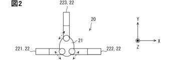
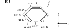
- FIG. It is a top view which shows a hand part. It is a side view which shows a hand part.
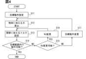
- 3 is a flowchart showing torque determination processing executed by a control unit. It is a figure showing the force applied to an object. It is a figure showing the force applied to a joint.
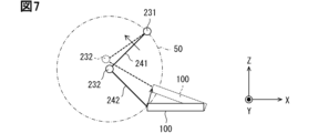
- FIG. 3 is a diagram showing the trajectory of an object and the movement of a first joint.
- FIG. 3 is a diagram showing the trajectory of an object and the movement of a first joint.
- FIG. 3 is a diagram showing the relationship between dynamic operation and back drive.
- FIG. 3 is a diagram showing the relationship between static operations and backdrive.
- 5 is a flowchart illustrating processing executed by a control unit.
- FIG. 3 is a diagram showing an operation when performing a dynamic operation.
- FIG. 3 is a diagram showing an operation when performing a static operation. It is a figure which shows operation
- FIG. 7 is a diagram showing a robot hand according to a second embodiment. It is a figure showing the robot hand concerning a 3rd embodiment.
- 5 is a flowchart illustrating processing executed by a control unit.
- FIG. 1 is a diagram showing a schematic configuration of a robot hand according to this embodiment.
- the robot hand 10 includes a hand section 20, a drive section 30, and a control section 40.
- the hand portion 20 is simplified and only one finger portion 22, which will be described later, is shown.
- the robot hand 10 is sometimes referred to as a hand device, a robot hand system, or the like.
- the robot hand 10 operates an object.
- the robot hand 10 may be attached to the tip of a robot arm (not shown), or may be used alone.
- FIG. 2 is a top view showing the hand section 20.
- FIG. 3 is a side view showing the hand section 20.
- the X direction, Y direction, and Z direction are in a positional relationship that is orthogonal to each other. 2 and 3 show an example of the hand section 20.
- the hand portion 20 includes a base portion 21 and finger portions 22 supported by the base portion 21.
- the base 21 is sometimes referred to as a palm.
- the finger section 22 includes a first finger section 221, a second finger section 222, and a third finger section 223.
- the three finger parts 22 are each supported by the base part 21.
- the first finger portion 221 and the second finger portion 222 are arranged side by side in the X direction so as to face each other in the bent state. In the X direction, the first finger portion 221 is continuous with one end of the base portion 21, and the second finger portion 222 is continuous with the other end of the base portion 21. In the Y direction, the third finger portion 223 is continuous with one end of the base portion 21 .
- Each of the finger parts 22 includes two joints 23 and two links 24.
- the finger portion 22 is configured to include a link mechanism.
- Joint 23 has a rotation axis.
- the joint 23 is configured to be rotatable around a rotation axis.
- the joint 23 includes a first joint 231 and a second joint 232 provided closer to the fingertip than the first joint 231 .
- the link 24 includes a first link 241 and a second link 242 that connect a first joint 231 and a second joint 232.
- the finger portion 22 is connected to the base portion 21 via a first joint 231.
- the first link 241 is connected to the base 21 via the first joint 231.
- the base 21 and the first link 241 are relatively rotatable around the rotation axis of the first joint 231. Due to the rotation, the angle (angle ⁇ 1 described below) formed by the first link 241 with respect to the base 21 changes.
- the second link 242 is connected to the first link 241 via the second joint 232.
- the first link 241 and the second link 242 are relatively rotatable around the rotation axis of the second joint 232. Due to the rotation, the angle formed by the second link 242 with respect to the first link 241 (angle ⁇ 2 described below) changes.
- the second link 242 forms the tip of the finger portion 22 .
- the rotation axis of the first joint 231 and the rotation axis of the second joint 232 are substantially parallel to each other.
- Substantially parallel includes not only completely parallel but also approximately parallel.
- the rotation axis of the first joint 231 and the rotation axis of the second joint 232 are substantially parallel to the Y direction.
- Each finger portion 22 may have an elastic member (not shown) on at least a portion of the surface portion excluding the joint 23.
- an elastic member such as rubber or urethane, for example, friction with an object can be increased and operation can be stabilized.
- the number of finger portions 22 included in the hand portion 20 is not limited to three.
- the hand portion 20 may include at least one finger portion 22, preferably a plurality of finger portions 22.
- the hand section 20 may include two finger sections 22 or four or more finger sections 22.
- the finger portion 22 may include three or more joints 23.
- the joint 23 having a rotation axis substantially parallel to the Z direction may be provided at a position closest to the base 21. This allows the finger portion 22 to open and close laterally, as shown by the dashed-dotted arrow in FIG. In other words, it is possible to provide the finger portion 22 that can be bent and opened/closed. Note that all the finger sections 22 may be provided so as to be able to open and close, or only some of the finger sections 22 may be provided so that the finger sections 22 can be opened and closed.
- the first joint 231 is provided at a position closer to the base 21 than the second joint 232
- the second joint 232 is provided at a position closer to the fingertip than the first joint 231.
- the joint 23 closest to the base 21 may be the first joint 231
- the joint 23 second closest to the base 21 may be the first joint 231.
- the joint 23 closest to the fingertip may be the second joint 232
- the joint 23 second closest to the fingertip may be the second joint 232.
- FIG. 1 shows an example of the drive section 30.
- the drive unit 30 is sometimes referred to as a drive mechanism, an actuator, or the like.
- FIG. 1 shows only the elements of the drive section 30 that correspond to the first joint 231 of the first finger section 221.
- the first joint 231 of the first finger portion 221 may be simply referred to as the first joint 231 below.
- the drive unit 30 includes a first drive unit 31 and a second drive unit 32 as elements that drive the first joint 231.
- the first drive section 31 and the second drive section 32 drive a common first joint 231.
- the first joint 231 corresponds to a common joint.
- the first drive unit 31 and the second drive unit 32 act on the first joint 231 in a direction that applies at least a force to an object.
- the first drive section 31 and the second drive section 32 differ in ease of back driving.
- the first drive section 31 is configured to be easier to backdrive than the second drive section 32.
- the second drive section 32 is configured to be more difficult to backdrive than the first drive section 31 .
- the first drive unit 31 includes a motor 311, a reduction gear 312, and a wire 313.
- the second drive unit 32 includes a motor 321, a speed reducer 322, and a wire 323.
- the motor 311 is shown as M1
- the motor 321 is shown as M2.
- the speed reducer 312 is shown as G1
- the speed reducer 322 is shown as G2.
- the reduction ratio of the reduction gear 312 is smaller than the reduction ratio of the reduction gear 322.
- the reduction ratio of the reduction gear 312 is about 1 to 5, and the reduction ratio of the reduction gear 322 is about 30 to 60. Since the reduction ratios are different, the first drive section 31 and the second drive section 32 have different ease of backdriving.
- the joint 23 driven by the drive unit 30 includes, for example, a pulley (not shown) coaxially therewith.
- the wire 313 of the first drive section 31 is wound around the pulley of the first joint 231.
- the motor 311 transmits the power adjusted by the reducer 312 to the pulley via the wire 313.
- the motor 311 drives the first joint 231 by applying a tensile force to the wire 313 via the reducer 312 .
- the motor 311 applies a pulling force to the wire 313, thereby applying a torque to the first joint 231 to rotate it in one direction around the rotation axis.
- the first joint 231 rotates in a direction that applies force to the object 100 due to the pulling force of the motor 311 . In the example shown in FIG. 1, the first joint 231 rotates counterclockwise.
- the wire 323 of the second drive unit 32 is wound around the pulley of the first joint 231.
- the motor 321 transmits the power adjusted by the reducer 322 to the pulley via the wire 323.
- the motor 321 drives the first joint 231 by applying a tensile force to the wire 323 via the reducer 322 .
- the motor 321 applies a pulling force to the wire 323, thereby applying a torque to the first joint 231 to rotate it in one direction around the rotation axis.
- the first joint 231 rotates in a direction that applies force to the object 100 due to the pulling force of the motor 321 via the wire 323 . In the example shown in FIG. 1, the first joint 231 rotates counterclockwise.
- the second drive section 32 further includes a wire 324.
- the wire 324 is also wound around the pulley of the first joint 231.
- the motor 321 transmits the power adjusted by the reducer 322 to the pulley via the wire 324.
- the motor 321 applies a pulling force to the wire 324 via the speed reducer 322, thereby applying torque to the first joint 231 to rotate in the opposite direction to the one direction.
- the first joint 231 rotates in the opposite direction to the direction in which force is applied to the object 100 due to the pulling force of the motor 321 via the wire 324 .
- the first joint 231 rotates clockwise. Rotation in one direction is sometimes called forward rotation, and rotation in the opposite direction to the one direction is sometimes called reverse rotation.
- elements of the drive unit 30 that correspond to the second joint 232 of the first finger portion 221 and the joints 23 of the other finger portions 22 have similar configurations. That is, the first drive section 31 and the second drive section 32 are individually provided for all the joints 23. Instead, the first drive section 31 and the second drive section 32 may be individually provided only in a part of the joint 23. For example, both the first drive section 31 and the second drive section 32 may be provided for a part of the joint 23, and only one of the first drive section 31 and the second drive section 32 may be provided for the remaining joints 23. good. For example, in the case where a part of the joint 23 is not driven by the drive section 30, such as a free joint, the first drive section 31 and the second drive section 32 may be provided for the remaining joints 23.
- the drive unit 30 is not limited to the above configuration. V-belts may be used instead of the wires 313, 323, 324.
- the motors 311 and 321 may be built into the joint 23 or the link 24. For example, if sufficient output torque can be obtained only by the motor 311, a configuration may be adopted in which the reducer 312 with a small reduction ratio is excluded.
- control section 40 includes a control circuit 41 and a drive circuit 42.
- Control circuit 41 is sometimes referred to as a controller.
- the control circuit 41 acquires information that affects the motion of the object from a camera, sensor, etc. (not shown), and sets target torques for each joint 23 necessary for making the object perform the target motion based on the acquired information. .
- the control circuit 41 outputs a drive command according to the target torque to the drive circuit 42.
- the control circuit 41 includes, for example, a processor 411 and a memory 412.
- the memory 412 includes, for example, RAM and ROM.
- RAM is an abbreviation for Random Access Memory.
- ROM is an abbreviation for Read Only Memory.
- the processor 411 executes predetermined processing (control) by executing a program stored in the ROM while using the RAM as a temporary storage area.
- the processor 411 constructs a plurality of functional units by executing a plurality of instructions included in a program.
- the program storage medium is not limited to ROM.
- various storage media such as HDD and SSD can be used.
- HDD is an abbreviation for Hard-disk Drive.
- SSD is an abbreviation for Solid State Drive.
- the processor 411 is, for example, a CPU, MPU, GPU, DFP, or the like.
- CPU is an abbreviation for Central Processing Unit.
- MPU is an abbreviation for Micro-Processing Unit.
- GPU is an abbreviation for Graphics Processing Unit.
- DFP is an abbreviation for Data Flow Processor.
- the control circuit 41 may be realized by combining multiple types of arithmetic processing devices such as a CPU, MPU, and GPU.
- the control circuit 41 may be realized as an SoC. SoC is an abbreviation for System on Chip.
- the control circuit 41 may be realized using ASIC or FPGA.
- ASIC is an abbreviation for Application Specific Integrated Circuit.
- FPGA is an abbreviation for Field-Programmable Gate Array.
- the drive circuit 42 is sometimes referred to as a motor driver.
- the drive circuit 42 applies a drive current to the motors 311, 321 according to the drive command, and operates the motors 311, 321.
- FIG. 4 is a flowchart showing the torque determination process executed by the control unit 40.
- FIG. 5 is a diagram for explaining the force applied to an object.
- FIG. 6 is a diagram for explaining torque applied to the first joint 231 and the second joint 232.
- the control unit 40 executes the process shown in FIG. 4.
- the target range is defined by time, location, etc.
- the user inputs that the predetermined position of the object 100 be raised by 0.5 cm or more within 0.5 seconds.
- the predetermined position may be, for example, the point of action on the object 100, or the upper end of the contact surface (end surface) with which the finger portion 22 comes into contact. It may also be the lower end of the contact surface.
- the parameters are parameters that affect the operation of the object 100, specifically parameters related to the hand section 20, parameters related to the object 100, and parameters related to the environment.
- Hand parameters include J1g, J2g, L1, L2, Tc, Tg, Tr, etc.
- JIg is the moment of inertia of the first link 241
- J2g is the moment of inertia of the second link 242.
- L1 is the length of the first link 241
- L2 is the length of the second link 242.
- Tc torque due to centrifugal force/Coriolis force
- Tg is torque due to gravity
- Tr is torque due to resistance forces such as viscosity, springs, and friction.
- the object parameters include the size, mass, maximum friction coefficient, softness, center of gravity position, etc. of the object 100.
- the size affects the length L of the object 100 and the moment of inertia J of the object 100.
- the length L is the length of the displaced portion.
- the mass affects the spring constant k and the moment of inertia J when the object rotates.
- the maximum friction coefficient influences the friction coefficient ⁇ .
- Softness affects the length L, the spring constant k, and the viscosity coefficient c when the object rotates.
- the position of the center of gravity affects the moment of inertia J.
- the environmental parameters include the distance between the object position and the fixed position.
- the distance between the object position and the fixed position affects the coordinates (x3, z3) of the fulcrum 101.
- the fixed position is the position of a fixed object such as a wall.
- the position of the fulcrum 101 changes depending on the softness of the object, and the softer the object, the shorter the length L of the displaced portion.
- the user inputs a variation range for at least one of the above parameters.
- the variation range the user inputs that the softness varies between -50% and 100%.
- the control circuit 41 of the control unit 40 sets the target motion (step S11).
- the control circuit 41 sets the position, velocity, acceleration, etc. within the input range. For example, the control circuit 41 sets, as the target operation, to float a predetermined position of the object 100 with 0% variation in softness by 1.5 cm in 0.5 seconds.
- the control circuit 41 calculates the angle ⁇ .
- the angle ⁇ is the angle that the object 100 makes with respect to the reference plane.
- the control circuit 41 calculates the force to be applied to the object 100 in order to realize the target motion (step S12).
- the control circuit 41 solves the inverse kinematics and calculates the force to be applied to the object 100.
- the forces applied to the object 100 are a force Fs (frictional force) for moving the object 100 and a force Fd (normal force) for preventing the object 100 from slipping.
- Equation 1 is a calculation formula for the frictional force Fs.
- the first term on the right side represents inertial resistance
- the second term represents viscous resistance
- the third term represents elastic resistance.
- Equation 2 is a required expression for the normal force Fd.
- control circuit 41 sets a target torque (driving force) to be applied to each joint 23 (step S13).
- the control circuit 41 solves the inverse dynamics and sets the torque T1 to be applied to the first joint 231 and the torque T2 to be applied to the second joint 232.
- step S13 the control circuit 41 first sets the normal force Fd as shown in Equation 3.
- kd is a value of 1 or more.
- the control circuit 41 sets, for example, 1.5 as the initial value of kd.
- control circuit 41 coordinately transforms the forces Fs and Fd applied to the object 100 into a force Fx in the X direction and a force Fz in the Z direction, using Equations 4 and 5.
- the control circuit 41 calculates the angles ⁇ 1 and ⁇ 2 from Equation 6 and Equation 7, which indicate the positional relationship between the hand section 20 and the object 100.
- the angle ⁇ 1 is the angle formed by the first link 241 with respect to the base 21, as described above.
- the angle ⁇ 2 is an angle formed by the second link 242 with respect to the first link 241.
- (x1, z1) shown in FIG. 6 are the coordinates of the second joint 232
- (x2, z2) are the coordinates of the point of action 102 of the object 100.
- (x3, z3) are the coordinates of the fulcrum 101 of displacement in the object 100.
- control circuit 41 calculates and sets the torques T1 and T2 using the equation of motion of the second joint 232 shown in Equation 8 and the equation of motion of the first joint 231 shown in Equation 9.
- the control circuit 41 sets torques T1 and T2 in the direction of applying force to the object 100.
- Equation 8 the first term on the right side is the inertial resistance torque
- the second term is the reaction force from the object 100
- the third term is the torque due to centrifugal force/Coriolis force
- the fourth term is the torque due to gravity
- the fifth term is This is torque due to resistance force.
- the second to fifth terms are external forces acting on the second joint 232.
- the first term on the right side is the inertial resistance torque
- the second term is the reaction force from the object 100
- the fourth term is the torque due to centrifugal force/Coriolis force
- the fifth term is the torque due to gravity
- the sixth term is This is torque due to resistance force.
- the second to sixth terms are external forces acting on the first joint 231.
- the control circuit 41 uses angles ⁇ 1 and ⁇ 2 calculated using Equations 6 and 7, and information (parameters) obtained from a camera, a sensor, etc. The control circuit 41 sets the torques T1 and T2 based on the estimated value of the external force.
- Equation 11 is obtained.
- the control circuit 41 After setting the torques T1 and T2, the control circuit 41 then determines whether the object 100 can operate within the target range even if the parameters vary (step S14). For example, the control circuit 41 changes the softness setting within the above-mentioned variation range, and determines whether the object 100 can move within the target range within the variation range. If the control circuit 41 determines that operation is possible within the target range even if the parameters vary, the control circuit 41 ends the torque determination process.
- step S14 determines whether kd in Equation 4 can be changed (step S15), and if possible, changes the value of kd. change (step S16). Then, the processes of steps S13 and S14 are executed again.
- the control circuit 41 determines that operation within the target range is not possible in step S14 after changing kd, it executes the process of step S15 again. Then, if it is possible to change, the value of kd is changed again.
- the control circuit 41 determines that kd cannot be changed, and changes the target motion of the object 100 within the target range (step S17). Then, the processes of steps S12, S13, and S14 are executed again. That is, if the motion of the object 100 deviates from the target range, the value of kd is first changed, and if it still deviates from the target range, the target motion of the object 100 is changed within the target range. In this way, torques T1 and T2 are determined that allow operation within the target range even if parameters (for example, softness) vary.
- the control unit 40 may have a learning function, for example, and may autonomously set the parameter variation range.
- control unit 40 control circuit 41
- the processing executed by the control unit 40 is not limited to the example shown in FIG. 4.
- a configuration may be adopted that does not take parameter variations into account.
- the processes of steps S14, S15, S16, and S17 are unnecessary.
- a user may input a target motion of the object 100.
- the processing of steps S11, S14, S15, S16, and S17 becomes unnecessary.
- ⁇ Backdrive> 7 and 8 are diagrams for explaining the trajectory of the object 100 and the movement of the first joint 231.
- the virtual circle shown by the dashed line in FIGS. 7 and 8 is centered on the rotation axis of the second joint 232 before the displacement of the object 100, and reaches the point of contact (point of force) with the object 100 in the finger section 22, that is, the second link 242. It is a circle whose radius is .
- the broken lines in FIGS. 7 and 8 indicate the state after displacement.
- components other than torque T1 are external forces acting on the first joint 231.
- the external force is the sum of the reaction force Te from the object 100, torque T2, torque Tc1 due to centrifugal force/Coriolis force, torque Tg1 due to gravity, and torque Tr1 due to resistance force. If the object 100 is hard and the reaction force is large, the trajectory of the predetermined position (for example, the point of application) of the object 100 will be a close one, and if it is soft and the reaction force is small, the trajectory will be a long one. In other words, the trajectory of the object 100 with a large reaction force tends to be inside the virtual circle. The trajectory of the object 100 with a small reaction force tends to be outside the virtual circle.
- the first joint 231 in order to displace the object 100 so that the trajectory is inside the virtual circle, the first joint 231 needs to rotate in the opposite direction to the direction in which force is applied to the object 100, that is, rotate in the opposite direction. There is.
- the external force including the reaction force is larger than the torque T1
- the torque T1 that is, when the total value of the torques of the first joint 231 (the right side of Equation 11) is negative
- the first joint 231 rotates in the opposite direction as shown in FIG. In this way, the reverse rotation that occurs when the external force including the reaction force is larger than the torque T1 is backdrive.
- the first joint 231 in order to displace the object 100 so that the trajectory is outside the virtual circle, the first joint 231 needs to rotate in a direction that applies force to the object 100, that is, rotate in the normal direction.
- the external force including the reaction force is smaller than the torque T1
- the torque T1 that is, when the total value of the torques of the first joint 231 is positive
- FIG. 9 is a diagram showing the relationship between dynamic operations and backdrive.
- FIG. 10 is a diagram showing the relationship between static operation and back drive.
- Methods for manipulating objects can be broadly divided into dynamic manipulation and static manipulation.
- the dynamic operation is an operation of moving the fingertips of the hand section 20.
- the static operation is an operation in which the fingertips of the hand section 20 are fixed.
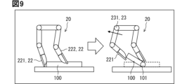
- FIG. 9 An example of a dynamic operation is the flip-up shown in FIG.
- the tip of the first finger 221 contacts one of the ends of the object 100, and the tip of the second finger 222 presses an intermediate position of the object 100.
- the object 100 is turned over by moving the first finger portion 221.
- the first joint 231 of the first finger portion 221 backdrives due to the external force including the reaction force being larger than the torque T1
- the object 100 is turned up using the portion pressed by the second finger portion 222 as the fulcrum 101.
- the fingertip will follow the object 100 even if the trajectory is inside the virtual circle as described above.
- the robot hand 10 automatically adjusts the trajectory of the finger 22 according to the behavior of the object 100. Thereby, robustness can be improved.
- FIG. 10 An example of a static operation is the pick-up shown in FIG.
- the tip of the first finger 221 is in contact with one of the ends of the object 100
- the tip of the second finger 222 is in contact with another one of the ends of the object 100.
- the entire hand section 20 is moved upward to pick up the object 100.
- the first joint 231 of the first finger portion 221 will backdrive as shown in FIG. 10. Due to the back drive, the tip of the first finger portion 221 separates from the object 100, and the gripping state is released.
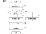
- FIG. 11 is a flowchart illustrating an example of a process executed by the control unit 40 to cause the object 100 to perform a target motion, that is, an example of a method of controlling the robot hand 10.
- FIG. 12 is a diagram showing the operation when performing a dynamic operation.
- FIG. 13 is a diagram showing the operation when performing a static operation.
- FIG. 14 is a diagram showing the operation during movement.
- FIGS. 12, 13, and 14 also show only the elements of the drive unit 30 that correspond to the first joint 231 of the first finger 221.
- FIG. 12 shows flipping up as an example of a dynamic operation.
- FIG. 13 shows picking up as an example of a static operation.
- control circuit 41 of the control unit 40 first determines how to operate the object 100 (step S21).
- the control circuit 41 determines, for example, whether the operation is dynamic or static.
- the control circuit 41 may determine a more specific operation, such as turning up or picking up.
- the control circuit 41 determines the operating method based on the user's input, for example. As an example, the control circuit 41 may determine the operating method by acquiring the operating method input by the user. The control circuit 41 may determine and determine the operating method based on the user's input. At least a portion of the user input may overlap with the user input used in the torque determination process. Information about cameras, sensors, etc. may be acquired, and the control circuit 41 may determine the operating method based on the acquired information.
- control circuit 41 determines whether backdrive is necessary based on the operating method (step S22). As described above, in the case of dynamic operations, it is preferable to adopt a configuration that facilitates backdriving. In the case of static operation, it is preferable to adopt a configuration that is difficult to backdrive. The control circuit 41 determines that a backdrive is necessary in the case of a dynamic operation, and determines that a backdrive is not required in the case of a static operation.
- the control circuit 41 selects the first drive section 31 as the drive section 30 to be used preferentially (step S23).
- the first drive section 31 is configured to be easier to backdrive than the second drive section 32. For this reason, it is preferable to suppress the second drive unit 32, which has a configuration that makes it difficult to backdrive, from interfering with the drive of the first joint 231.
- the control circuit 41 selects the first drive unit 31 and cuts off the power transmission path of the second drive unit 32 that is not used for operating the object 100. In other words, the power transmission path of the second drive unit 32 that does not drive the first joint 231 is cut off.
- control circuit 41 controls the motor 321 to loosen the wires 323 and 324 of the second drive unit 32, as shown in FIG.
- the wires 323 and 324 have slack portions 323a and 324a.
- the control circuit 41 selects the second drive section 32 as the drive section 30 to be used preferentially (step S24).
- the second drive section 32 is configured to be more difficult to backdrive than the first drive section 31.
- the control circuit 41 may interrupt the power transmission path of the first drive unit 31 that is not used to manipulate the object 100, that is, does not drive the first joint 231.
- the first drive unit 31, which is configured to easily backdrive, has little or no influence on the drive of the first joint 231, or even if it does, the influence is small. Therefore, the control circuit 41 does not need to interrupt the power transmission path of the first drive section 31.
- control circuit 41 does not allow the wire 313 of the first drive unit 31 to become loose, as shown in FIG. Since the wire 324 has the slack portion 324a, it is possible to suppress the power transmission path on the wire 324 side from affecting the drive of the first joint 231. When the wire 313 is made loose, it is possible to prevent the first drive section 31 from affecting the drive of the first joint 231.
- the control circuit 41 preferentially selects the driving portion 30 according to the operation.
- the control circuit 41 selects the second drive unit 32. Since the second drive section 32 has a large reduction ratio, the finger section 22 can be moved.
- the wire 323 has the slack portion 323a, it is possible to suppress the power transmission path on the wire 323 side from affecting the drive of the first joint 231.
- the first drive unit 31 may be driven to loosen the wire 313 while applying a constant reverse rotational torque to the first joint 231 by the second drive unit 32 via the wire 324. Thereby, the first finger portion 221 (22) can be moved at high speed.
- control circuit 41 determines the torque for the selected drive unit 30 (step S25). This torque determination process is the process shown in FIG. Then, the control circuit 41 executes control so as to apply the torque determined in step S25 to the corresponding joint 23 (step S26). Then, the series of processing ends.
- the various torques shown in Equation 11 and the like indicate torques when the reduction ratio is 1, that is, there is no influence of the reduction ratio.
- the torques T1 and T2 when the reduction ratio is 1 are sometimes referred to as motor torques.
- the torque T1 when the reduction ratio is R is the torque T1 when the reduction ratio is 1, that is, the motor torque multiplied by the reduction ratio.
- the reaction force Te is Te/R.
- the torque T1 becomes large and the external force acting on the first joint 231 becomes small. This is advantageous for operations that require a large force on the object 100, such as when the object 100 is heavy.
- the torque T1 becomes small and the external force acting on the first joint 231 becomes large. This makes it easier for the first joint 231 to backdrive. This is advantageous for operations that apply a small force to the object 100, such as when the object 100 is light or soft.
- the motor torque of the first drive section 31 is Tm1
- the motor torque of the second drive section 32 is Tm2.
- the reduction ratio of the reduction gear 312 is set to 1
- the reduction ratio of the reduction gear 322 is set to 50.
- Te is assumed as the external force.
- the first drive unit 31 is selected and a tensile force is applied to the wire 313 via the reducer 312, thereby driving the first joint 231.
- the forward rotational torque acting on the first joint 231 is Tm1.
- the reverse rotational torque acting on the first joint 231 is Te. Therefore, the first joint 231 is likely to backdrive.
- the second drive unit 32 is selected and the first joint 231 is driven by applying a tensile force to the wire 323 via the reduction gear 322.
- the forward rotational torque acting on the first joint 231 is 50 ⁇ Tm2.
- the reverse rotational torque acting on the first joint 231 is Te/50. Since the reverse rotation torque is 1/50 due to the reduction ratio, it cannot overcome the torque of inertia, viscosity, friction, etc. of the motor 321 and the reduction gear 322, and the first joint 231 is difficult to backdrive. Further, since it is possible to obtain 50 times the forward rotational torque by the reduction ratio, the output of the motor 321 can be reduced to, for example, 1/50. Thereby, the motor 321 can be downsized.
- the second drive unit 32 is selected and the first joint 231 is driven by applying a tensile force to the wire 324 via the reducer 322.
- the reverse rotational torque acting on the first joint 231 is 50 ⁇ Tm2. Thereby, the first finger portion 221 can be moved.
- FIG. 11 shows an example in which the torque determination process is performed in step S25
- the control circuit 41 may perform torque determination processing before executing step S26.
- the torque determination process may be performed while selecting the drive unit in the process of step S23 or step S24.
- a torque determining process may also be performed.
- the control circuit 41 may perform the torque determination process in parallel with the process shown in FIG. 11.
- control circuit 41 selects the first drive section 31 or the second drive section 32
- the control circuit 41 is not limited to this.
- a configuration may be adopted in which either only the first drive section 31, only the second drive section 32, or the first drive section 31 and the second drive section 32 are selected.
- forward rotational torque can be increased compared to a configuration in which only the second drive section 32 is selected.
- the robot hand 10 of this embodiment includes a first drive unit 31 and a second drive unit 32 as drive units 30 that act in a direction to apply force to the object 100 with respect to a first joint 231 that is a common joint.
- the first drive section 31 has a configuration that makes it easy to backdrive
- the second drive section 32 has a configuration that makes it difficult to backdrive.
- the operations of the object 100 include, for example, operations that require a backdrive, operations that may cause a backdrive, and operations that do not require a backdrive.
- the control unit 40 selects the drive unit 30 suitable for operating the object 100. Thereby, operability can be improved.
- the control unit 40 selects at least the second drive unit 32 when the object 100 is operated statically, that is, when the fingertip of the hand unit 20 is fixed.
- the second drive section 32 is difficult to backdrive. Therefore, it is possible to prevent the fingertip from separating from the object 100 and becoming unable to perform the desired operation. In this way, the operability when statically manipulating the object 100 can be improved.
- the control unit 40 selects the first drive unit 31 when the object 100 is dynamically operated, that is, when the fingertip of the hand unit 20 is moved.
- the first drive section 31 is easy to backdrive.
- the joint 23 rotates depending on the magnitude relationship between the external force including the reaction force and the torque applied from the drive unit 30. For example, when the external force acting on the first joint 231 is smaller than the torque T1, the first joint 231 rotates in the normal direction. As a result, the trajectory of the tip of the finger portion 22 is outside the virtual circle. When the external force acting on the first joint 231 is larger than the torque T1, the first joint 231 rotates in the opposite direction. As a result, the trajectory of the tip of the finger portion 22 becomes inside the virtual circle. In this way, the finger portion 22 follows the object 100.
- the robot hand 10 automatically adjusts the trajectory of the finger 22 according to the behavior of the object 100. In this way, the operability when dynamically manipulating the object 100 can be improved.
- Dynamic operations are not limited to flipping.
- the first drive unit 31 is suitable for approaching the object 100 and operating relatively small objects. As described above, by selecting the first drive unit 31, it is possible to cause the finger unit 22 to follow the object 100 whose movement cannot be accurately predicted. For example, it is suitable for an operation of grasping a flexible object 100 such as clothes, a bag, a pillow, a futon, etc. while searching for a grasping position, and an operation of opening a flexible bag that is the object 100. It is also suitable for operations such as grasping a soft ball, which is the object 100, and applying a sticker to the surface of the soft object 100. It is also suitable for operations that require the finger portion 22 to follow an object 100 having a complicated shape such as a curved surface.
- the ease of backdriving can be varied by the spring constant and damper constant of the power transmission path.
- the spring constant is small, the external force required to backdrive the first joint 231 with respect to the torque T1 becomes small. Therefore, it becomes easier to backdrive.
- the spring constant is large, the external force required to backdrive the first joint 231 becomes large. Therefore, it becomes difficult to backdrive.
- the damper constant is small, it becomes easier to backdrive, and if the damper constant is large, it becomes difficult to backdrive.
- the ease of backdriving differs due to the different reduction ratios of the reducers.
- the reduction ratio of the reduction gear 312 (first reduction gear) included in the first drive unit 31 is smaller than the reduction ratio of the reduction gear 322 (second reduction gear) included in the second drive unit 32.
- the motor 321 can be downsized. In other words, it is possible to reduce the size of the motor 321 and, by extension, the robot hand 10 while improving operability.
- the drive unit 30 may be built into the joint 23 or the like. In other words, it may be configured without wires.
- the first drive section 31 and the second drive section 32 include wires 313 and 323 that rotate the first joint 231 (common joint) in the normal direction by transmitting power.
- the control unit 40 loosens the wire of the drive unit 30 that is not used for operating the object 100, that is, the drive unit 30 that does not drive the first joint 231.
- the wire 323 of the second drive section 32 is made loose. Thereby, it is possible to suppress the second drive section 32 from influencing the drive of the first joint 231 through the wire 323. Therefore, the operability can be further improved with a simple configuration.
- the first drive unit 31 and the second drive unit 32 may include at least wires 313 and 323 that rotate the first joint 231 in the forward direction, for example. That is, the first drive section 31 may include only the wire 313, and the second drive section 32 may include only the wire 323.
- the second drive unit 32 includes a wire 324 that rotates the first joint 231 in the opposite direction, for example.
- the control unit 40 when selecting and using the first drive unit 31, the control unit 40 also allows the wire 324 of the second drive unit 32 to be loosened. Thereby, it is possible to suppress the second drive section 32 from influencing the drive of the first joint 231 through the wire 324. Therefore, the operability can be further improved with a simple configuration.
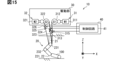
- FIG. 15 is a diagram showing a part of the robot hand 10 according to this embodiment.
- the control unit 40 is illustrated in a simplified manner compared to FIG. Further, the connection between the control section 40 and the drive section 30 is omitted in the illustration.
- the first joint 231 of the first finger portion 221 will be explained as an example.
- the first drive section 31 includes a wire 313.
- the second drive section 32 includes wires 323 and 324.
- the wire 313 is provided with a spring mechanism 315.
- the wire 323 is provided with a spring mechanism 325.
- the wire 324 is provided with a spring mechanism 326.
- the control circuit 41 of the control unit 40 controls the spring constants of the spring mechanisms 315, 325, and 326. By providing the spring mechanisms 315, 325, and 326, the spring constants of the corresponding wires 313, 323, and 324 can be varied.
- the control circuit 41 controls the spring constant in at least one of the first drive section 31 and the second drive section 32.
- the control circuit 41 may make the spring constant of the wire 313 (spring mechanism 315) of the first drive unit 31 smaller when it is not used to drive the first joint 231 than when it is used to drive the first joint 231. .
- the spring constant is made small, it is possible to suppress the influence of the first drive section 31 on the drive of the first joint 231.
- the control circuit 41 may make the spring constant of the wire 323 (spring mechanism 325) of the second drive unit 32 smaller when it is not used to drive the first joint 231 than when it is used to drive the first joint 231. .
- the spring constant for example, in the case of static operation, power can be transmitted to the first joint 231 through the wire 323 in order to increase the spring constant.
- the spring constant is made small, it is possible to suppress the influence of the second drive section 32 on the drive of the first joint 231.
- the control circuit 41 may make the spring constant of the wire 324 (spring mechanism 326) of the second drive unit 32 smaller when it is not used to drive the first joint 231 than when it is used to drive the first joint 231. .
- the spring constant when moving the finger portion 22 without operating the object 100, power can be transmitted to the first joint 231 through the wire 324 in order to increase the spring constant.
- the spring constant is made small, it is possible to suppress the second drive unit 32 from influencing the drive of the first joint 231 through the wire 324.
- control unit 40 controls the spring constants of the wires 313, 323, and 324 when not used to drive the first joint 231 (common joint) in at least one of the first drive unit 31 and the second drive unit 32. is made smaller than the spring constant of the wires 313, 323, and 324 when used to drive the first joint 231. Thereby, operability can be further improved.
- the present invention is not limited to this.
- the control unit 40 may control a damper constant instead of the spring constant.
- the drive unit 30 includes a damper mechanism (not shown) configured to have a variable damper constant instead of the spring mechanisms 315, 325, and 326 described above. Damper mechanisms are provided on the corresponding wires 313, 323, 324.
- the control circuit 41 makes the damper constant of the wire 323 (damper mechanism) of the second drive unit 32 smaller when it is not used to drive the first joint 231 than when it is used to drive the first joint 231.
- the damper constant is made small, it is possible to suppress the influence of the second drive section 32 on the drive of the first joint 231. Therefore, operability can be further improved.
- This embodiment is a modification based on the previous embodiment, and the description of the previous embodiment can be used.
- the first drive unit 31 acted in a direction to apply a force to the object 100 with respect to the common joint.
- the first drive unit 31 may be configured to act not only in the direction in which force is applied to the object 100 with respect to the common joint, but also in the opposite direction.
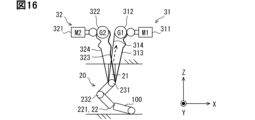
- FIG. 16 is a diagram showing a part of the robot hand 10 according to this embodiment.
- the control unit 40 is omitted from the illustration in FIG. 1.
- the first joint 231 of the first finger portion 221 will be explained as an example.
- the first drive section 31 includes a wire 314.
- the wire 314 is wound around the pulley of the first joint 231.
- the motor 311 transmits the power adjusted by the reducer 312 to the pulley via the wire 314.
- the motor 311 applies a pulling force to the wire 314 via the speed reducer 312, thereby applying a torque to the first joint 231 to rotate it in a direction opposite to the one direction described above.
- the first joint 231 rotates in the opposite direction due to the pulling force of the motor 311 via the wire 314 .
- the first drive section 31 includes wires 313 and 314.
- the first drive unit 31 can apply either a forward rotation torque or a reverse rotation torque to the first joint 231, which is a common joint.
- the second drive unit 32 includes wires 323 and 324 as in the previous embodiment.
- the second drive unit 32 can apply either a forward rotation torque or a reverse rotation torque to the first joint 231, which is a common joint.
- FIG. 17 is a flowchart showing the process executed by the control unit 40 to cause the object 100 to perform the target motion.
- the processes of steps S21, S22, S23, S24, S25, and S26 shown in FIG. 17 are similar to those in the preceding embodiment (see FIG. 11).
- the control circuit 41 executes the process of step S26, that is, control, so as to apply the torque determined in step S25 to the corresponding joint 23. Next, the control circuit 41 executes a stop process (step S27). Then, the series of processing ends.
- step S27 the control circuit 41 applies a torque in the opposite direction to the torque applied in step S26 to the first joint 231, for example, in order to suppress the first joint 231 from continuing to rotate due to inertia.
- the control circuit 41 drives the second drive unit 32 and applies forward rotational torque to the first joint 231 via the wire 323. This causes the first joint 231 to rotate forward. In other words, the first finger portion 221 (22) moves.
- the control circuit 41 drives the first drive section 31 and applies reverse rotation torque to the first joint 231 via the wire 314. As a result, the first joint 231, which is rotating in the forward direction, is stopped.
- forward rotational torque may be applied to the first joint 231 by the first drive unit 31 via the wire 313 while the second drive unit 32 is driven to loosen the wire 324.
- the first drive unit 31 applies forward rotational torque until the wire 324 is fully extended. Thereby, the first finger portion 221 (22) can be moved at high speed.
- the control circuit 41 drives the second drive unit 32 and applies reverse rotation torque to the first joint 231 via the wire 324. This causes the first joint 231 to rotate in the opposite direction. In other words, the first finger portion 221 (22) moves.
- the control circuit 41 drives the first drive section 31 and applies forward rotational torque to the first joint 231 via the wire 313. As a result, the first joint 231, which is rotating in the opposite direction, is stopped.
- the first drive unit 31 may be driven to loosen the wire 313 while applying a constant reverse rotational torque to the first joint 231 by the second drive unit 32 via the wire 324. In this case, the first finger portion 221 (22) can be moved at high speed.
- the first drive unit 31 and the second drive unit 32 of this embodiment can act on the first joint 231 (common joint) in a direction to apply force to the object 100.
- the first drive unit 31 and the second drive unit 32 can act on the first joint 231 in the opposite direction to the direction in which force is applied to the object 100. Therefore, operability can be further improved.
- first drive section 31 may be able to act on the first joint 231 in both directions.
- second drive unit 32 may be able to act on the first joint 231 in both directions. In either case, the first joint 231 can be stopped regardless of whether it is in the forward or reverse direction.
- the configuration described in this embodiment can be combined with the configuration described in the first embodiment and the configuration described in the second embodiment.
- Spatial relative terms such as “in”, “out”, “behind”, “below”, “low”, “above”, “high” etc. refer to a single element or feature as illustrated. It is used herein to facilitate descriptions that describe relationships to other elements or features. Spatially relative terms may be intended to encompass different orientations of the device during use or operation in addition to the orientation depicted in the figures. For example, when the device in the figures is turned over, elements described as being “below” or “beneath” other elements or features are oriented “above” the other elements or features. Thus, the term “bottom” can encompass both orientations, top and bottom. The device may be oriented in other directions (rotated 90 degrees or other orientations) and the spatially relative descriptors used in this specification shall be interpreted accordingly. .
- the drive unit includes a first drive unit (31) and a second drive unit (32) that act in a direction to apply force to an object with respect to a common joint that is the common joint,
- the first drive unit is configured to be easier to backdrive than the second drive unit
- the control unit is a robot hand that selects and uses the drive unit according to the operation of the object.
- the first drive section includes a first reduction gear (312),
- the second drive unit includes a second reduction gear (322),
- the robot hand according to technical idea 1, wherein a reduction ratio of the first reduction gear is smaller than a reduction ratio of the second reduction gear.
- the first drive unit and the second drive unit each have a wire (313, 323) that rotates the common joint in a direction that applies force to the object by transmitting power,
- the control section is configured to loosen the wire of the drive section that is not used for driving the common joint among the first drive section and the second drive section. robot hand.
- the first drive unit and the second drive unit each have a wire (313, 323) that rotates the common joint in a direction that applies force to the object by transmitting power,
- the wire has a variable spring constant or damper constant
- the control unit is configured to set a spring constant or a damper constant of the wire when not used to drive the common joint to a spring constant or a damper constant when used to drive the common joint.
- At least one of the first drive unit and the second drive unit is capable of acting on the common joint in a direction opposite to a direction in which force is applied to the object. robot hand.
Landscapes
- Engineering & Computer Science (AREA)
- Robotics (AREA)
- Mechanical Engineering (AREA)
- Manipulator (AREA)
Abstract
ロボットハンド(10)は、指部(22)と、駆動部(30)と、制御部(40)を備える。指部は、複数の関節(23)を有する。駆動部は、関節の少なくともひとつを駆動する。制御部は、駆動部を用いて関節の駆動を制御する。駆動部は、互いに共通の関節である共通関節に対して物体に力を加える向きに作用する第1駆動部(31)および第2駆動部(32)を含む。第1駆動部は、第2駆動部よりもバックドライブし易い構成である。制御部は、物体の操作に応じて駆動部を選択して用いる。
Description
この出願は、2022年4月28日に日本に出願された特許出願第2022-75081号を基礎としており、基礎の出願の内容を、全体的に、参照により援用している。
この明細書における開示は、ロボットハンドに関する。
特許文献1は、ロボットハンドを開示している。先行技術文献の記載内容は、この明細書における技術的要素の説明として、参照により援用される。
特許文献1に開示されたロボットハンドは、操作性に劣る。上記した観点において、または言及されていない他の観点において、ロボットハンドにはさらなる改良が求められている。
開示されるひとつの目的は、操作性を向上できるロボットハンドを提供することにある。
ここに開示されたロボットハンドは、
基部と、
複数の関節を有し、基部に支持された指部と、
関節の少なくともひとつを駆動する駆動部と、
駆動部を用いて関節の駆動を制御する制御部と、を備え、
駆動部は、互いに共通の関節である共通関節に対して物体に力を加える向きに作用する第1駆動部および第2駆動部を含み、
第1駆動部は、第2駆動部よりもバックドライブし易い構成とされ、
制御部は、物体の操作に応じて駆動部を選択して用いる。
基部と、
複数の関節を有し、基部に支持された指部と、
関節の少なくともひとつを駆動する駆動部と、
駆動部を用いて関節の駆動を制御する制御部と、を備え、
駆動部は、互いに共通の関節である共通関節に対して物体に力を加える向きに作用する第1駆動部および第2駆動部を含み、
第1駆動部は、第2駆動部よりもバックドライブし易い構成とされ、
制御部は、物体の操作に応じて駆動部を選択して用いる。
開示されたロボットハンドによれば、バックドライブのし易さが第1駆動部と第2駆動部とで異なる。制御部は、共通関節を駆動する駆動部を物体の操作に応じて選択する。物体の操作に適した駆動部を用いるため、操作性を向上することができる。
この明細書における開示された複数の態様は、それぞれの目的を達成するために、互いに異なる技術的手段を採用する。請求の範囲およびこの項に記載した括弧内の符号は、後述する実施形態の部分との対応関係を例示的に示すものであって、技術的範囲を限定することを意図するものではない。この明細書に開示される目的、特徴、および効果は、後続の詳細な説明、および添付の図面を参照することによってより明確になる。
以下、図面に基づいて複数の実施形態を説明する。なお、各実施形態において対応する構成要素には同一の符号を付すことにより、重複する説明を省略する場合がある。各実施形態において構成の一部分のみを説明している場合、当該構成の他の部分については、先行して説明した他の実施形態の構成を適用することができる。また、各実施形態の説明において明示している構成の組み合わせばかりではなく、特に組み合わせに支障が生じなければ、明示していなくても複数の実施形態の構成同士を部分的に組み合せることができる。
(第1実施形態)
図1は、本実施形態に係るロボットハンドの概略構成を示す図である。図1に示すように、ロボットハンド10は、ハンド部20と、駆動部30と、制御部40を備えている。図1ではハンド部20を簡素化し、後述する指部22を1本のみ示している。
図1は、本実施形態に係るロボットハンドの概略構成を示す図である。図1に示すように、ロボットハンド10は、ハンド部20と、駆動部30と、制御部40を備えている。図1ではハンド部20を簡素化し、後述する指部22を1本のみ示している。
ロボットハンド10は、ハンド装置、ロボットハンドシステムなどと称されることがある。ロボットハンド10は、物体を操作する。ロボットハンド10は、図示しないロボットアームの先端に取り付けられてもよいし、単体で使用してもよい。
<ハンド部>
図2は、ハンド部20を示す上面図である。図3は、ハンド部20を示す側面図である。X方向、Y方向、およびZ方向は、互いに直交する位置関係にある。図2および図3は、ハンド部20の一例を示している。
図2は、ハンド部20を示す上面図である。図3は、ハンド部20を示す側面図である。X方向、Y方向、およびZ方向は、互いに直交する位置関係にある。図2および図3は、ハンド部20の一例を示している。
ハンド部20は、基部21と、基部21に支持された指部22を備えている。基部21は、掌部と称されることがある。指部22は、第1指部221と、第2指部222と、第3指部223を含んでいる。3つの指部22は、それぞれ基部21に支持されている。第1指部221および第2指部222は、屈曲状態において互いに対向するように、X方向に並んで配置されている。X方向において、第1指部221は基部21の一端に連なり、第2指部222は基部21の他端に連なっている。Y方向において、第3指部223は、基部21の一端に連なっている。
指部22のそれぞれは、2つの関節23と、2つのリンク24を備えている。指部22は、リンク機構を備えて構成されている。関節23は、回転軸を有している。関節23は、回転軸周りの回転が可能に構成されている。関節23は、第1関節231と、第1関節231よりも指先側に設けられた第2関節232を含んでいる。リンク24は、第1関節231と第2関節232とを連結する第1リンク241と、第2リンク242を含んでいる。指部22は、第1関節231を介して基部21に連結されている。第1リンク241は、第1関節231を介して、基部21に連結されている。基部21および第1リンク241は、第1関節231の回転軸周りに相対的に回動可能となっている。回動により、基部21に対する第1リンク241のなす角度(後述の角度θ1)が変化する。
第2リンク242は、第2関節232を介して第1リンク241に連結されている。第1リンク241および第2リンク242は、第2関節232の回転軸周りに相対的に回動可能となっている。回動により、第1リンク241に対する第2リンク242のなす角度(後述の角度θ2)が変化する。第2リンク242は、指部22の先端をなしている。
共通(単一)の指部22において、第1関節231の回転軸と第2関節232の回転軸とは、互いに略平行である。略平行とは、完全に平行のみならず、概ね平行も含む。たとえば第1指部221において、第1関節231の回転軸と第2関節232の回転軸は、Y方向に略平行である。
各指部22は、関節23を除く表面部分の少なくとも一部に、図示しない弾性部材を有してもよい。ゴム、ウレタンなどの弾性部材を設けることで、たとえば物体との摩擦が増加し、操作を安定化することができる。
ハンド部20が備える指部22の本数は、3つに限定されない。ハンド部20は、指部22を少なくともひとつ備えればよく、好ましくは複数備えるとよい。ハンド部20は、2つの指部22を備えてもよいし、4つ以上の指部22を備えてもよい。
指部22が2つの関節23を備える例を示したが、これに限定されない。指部22は、関節23を3つ以上備えてもよい。3つ以上の関節23を備える場合、たとえばZ方向に略平行な回転軸を有する関節23を、基部21に対してもっとも近い位置に設けてもよい。これにより、指部22は、図2に一点鎖線の矢印で示すように、側方への開閉動作が可能になる。つまり、屈曲動作と開閉動作が可能な指部22を提供することができる。なお、すべての指部22が開閉動作可能に設けられてもよいし、一部の指部22のみが開閉動作可能に設けられてもよい。
3つ以上の関節23を備える構成において、第1関節231は第2関節232よりも基部21に近い位置に設けられ、第2関節232は第1関節231よりも指先に近い位置に設けられる。たとえば、基部21にもっとも近い関節23を第1関節231としてもよいし、2番目に近い関節23を第1関節231としてもよい。たとえば、指先にもっとも近い関節23を第2関節232としてもよいし、2番目に近い関節23を第2関節232としてもよい。
<駆動部>
図1は、駆動部30の一例を示している。駆動部30は、駆動機構、アクチュエータなどと称されることがある。便宜上、図1では、駆動部30のうち、第1指部221の第1関節231に対応する要素のみを示している。第1指部221の第1関節231を、以下では単に第1関節231と示すことがある。
図1は、駆動部30の一例を示している。駆動部30は、駆動機構、アクチュエータなどと称されることがある。便宜上、図1では、駆動部30のうち、第1指部221の第1関節231に対応する要素のみを示している。第1指部221の第1関節231を、以下では単に第1関節231と示すことがある。
駆動部30は、第1関節231を駆動する要素として、第1駆動部31と、第2駆動部32を含んでいる。第1駆動部31および第2駆動部32は、互いに共通の第1関節231を駆動する。第1関節231が、共通関節に相当する。第1駆動部31および第2駆動部32は、第1関節231に対して、少なくとも物体に力を加える向きに作用する。第1駆動部31と第2駆動部32とは、バックドライブのし易さが異なる。第1駆動部31は、第2駆動部32よりもバックドライブしやすい構成である。第2駆動部32は、第1駆動部31よりもバックドライブし難い構成である。
一例として、第1駆動部31は、モータ311と、減速機312と、ワイヤ313を備えている。第2駆動部32は、モータ321と、減速機322と、ワイヤ323を備えている。図1では、モータ311をM1、モータ321をM2と示している。減速機312をG1、減速機322をG2と示している。減速機312の減速比は、減速機322の減速比よりも小さい。たとえば、減速機312の減速比は1~5程度、減速機322の減速比は30~60程度である。減速比が異なることで、第1駆動部31と第2駆動部32とは、バックドライブのし易さが異なっている。
駆動部30により駆動される関節23は、たとえば図示しないプーリを同軸に備えている。第1駆動部31のワイヤ313は、第1関節231のプーリに巻き付けられている。モータ311は、減速機312により調整した動力を、ワイヤ313を介してプーリに伝達する。モータ311は、減速機312を介してワイヤ313に引っ張り力を加えることで、第1関節231を駆動する。モータ311は、ワイヤ313に引っ張り力を加えることで、第1関節231に対して回転軸周りの一方向に回転するトルクを加える。第1関節231は、モータ311の引っ張り力により、物体100に力を加える向きに回転する。図1に示す例において、第1関節231は反時計周りに回転する。
第2駆動部32のワイヤ323は、第1関節231のプーリに巻き付けられている。モータ321は、減速機322により調整した動力を、ワイヤ323を介してプーリに伝達する。モータ321は、減速機322を介してワイヤ323に引っ張り力を加えることで、第1関節231を駆動する。モータ321は、ワイヤ323に引っ張り力を加えることで、第1関節231に対して回転軸周りの一方向に回転するトルクを加える。第1関節231は、ワイヤ323を介したモータ321の引っ張り力により、物体100に力を加える向きに回転する。図1に示す例において、第1関節231は反時計周りに回転する。
第2駆動部32は、さらにワイヤ324を備えている。ワイヤ324も、第1関節231のプーリに巻き付けられている。モータ321は、減速機322により調整した動力を、ワイヤ324を介してプーリに伝達する。モータ321は、減速機322を介してワイヤ324に引っ張り力を加えることで、第1関節231に対して一方向とは逆向きに回転するトルクを加える。第1関節231は、ワイヤ324を介したモータ321の引っ張り力により、物体100に力を加える向きと逆向きに回転する。図1に示す例において、第1関節231は時計周りに回転する。一方向への回転を正回転、一方向とは逆向きの回転を逆回転と称することがある。
一例として、駆動部30のうち、第1指部221の第2関節232や他の指部22の関節23に対応する要素も、同様の構成である。つまり、すべての関節23に対して、第1駆動部31および第2駆動部32を個別に設けている。これに代えて、関節23の一部のみに、第1駆動部31および第2駆動部32を個別に設けてもよい。たとえば関節23の一部に対して第1駆動部31および第2駆動部32の両方を設け、残りの関節23に対して第1駆動部31および第2駆動部32の一方のみを設けてもよい。たとえば関節23の一部が駆動部30によって駆動されない関節、たとえばフリーの関節の場合、残りの関節23に対して第1駆動部31および第2駆動部32を設けてもよい。
駆動部30は、上記した構成に限定されない。ワイヤ313、323、324の代わりにVベルトを用いてもよい。モータ311、321は、関節23やリンク24に内蔵されてもよい。たとえばモータ311のみによって出力トルクが十分に得られるのであれば、減速比が小さい減速機312を排除した構成としてもよい。
<制御部>
図1に示すように、制御部40は、制御回路41と、駆動回路42を備えている。制御回路41は、コントローラと称されることがある。制御回路41は、図示しないカメラやセンサなどから物体の動作に影響を与える情報を取得し、取得した情報に基づいて、物体に目標動作をさせるために必要な各関節23の目標トルクを設定する。制御回路41は、目標トルクに応じた駆動指令を駆動回路42に出力する。
図1に示すように、制御部40は、制御回路41と、駆動回路42を備えている。制御回路41は、コントローラと称されることがある。制御回路41は、図示しないカメラやセンサなどから物体の動作に影響を与える情報を取得し、取得した情報に基づいて、物体に目標動作をさせるために必要な各関節23の目標トルクを設定する。制御回路41は、目標トルクに応じた駆動指令を駆動回路42に出力する。
制御回路41は、たとえばプロセッサ411と、メモリ412を備えている。メモリ412は、たとえばRAM、ROMを備えている。RAMは、Random Access Memoryの略称である。ROMは、Read Only Memoryの略称である。プロセッサ411は、RAMを一時的な記憶領域として用いつつROMに記憶されたプログラムを実行することで、所定の処理(制御)を実行する。プロセッサ411は、プログラムに含まれる複数の命令を実行することで、複数の機能部を構築する。プログラムの保存媒体は、ROMに限定されない。たとえばHDDやSSDなど、多様な記憶媒体を採用可能である。HDDは、Hard-disk Driveの略称である。SSDは、Solid State Driveの略称である。
プロセッサ411は、たとえばCPU、MPU、GPU、DFPなどである。CPUは、Central Processing Unitの略称である。MPUは、Micro-Processing Unitの略称である。GPUは、Graphics Processing Unitの略称である。DFPは、Data Flow Processorの略称である。制御回路41は、CPU、MPU、GPUなど、複数種類の演算処理装置を組み合わせて実現されてもよい。
制御回路41は、SoCとして実現されてもよい。SoCは、System on Chipの略称である。制御回路41は、ASICやFPGAを用いて実現されてもよい。ASICは、Application Specific Integrated Circuitの略称である。FPGAは、Field-Programmable Gate Arrayの略称である。
駆動回路42は、モータドライバと称されることがある。駆動回路42は、駆動指令に応じた駆動電流をモータ311、321に付与し、モータ311、321を動作させる。
<トルク決定処理>
図4は、制御部40が実行するトルク決定処理を示すフローチャートである。図5は、物体に加える力を説明するための図である。図6は、第1関節231および第2関節232に加えるトルクを説明するための図である。以下では、物体100の端部のひとつを壁などの固定物に押し当てて、ひとつの指部22で物体100をめくり上げる操作の例を用いて説明する。
図4は、制御部40が実行するトルク決定処理を示すフローチャートである。図5は、物体に加える力を説明するための図である。図6は、第1関節231および第2関節232に加えるトルクを説明するための図である。以下では、物体100の端部のひとつを壁などの固定物に押し当てて、ひとつの指部22で物体100をめくり上げる操作の例を用いて説明する。
たとえばユーザにより、制御部40に対して物体動作の目標範囲およびパラメータのばらつき範囲が入力されると、制御部40は図4に示す処理を実行する。目標範囲は、時間、位置などで規定される。目標範囲の一例として、ユーザは、物体100の所定位置を0.5s以内に0.5cm以上浮かせることを入力する。所定位置は、たとえば物体100における作用点でもよいし、指部22が接触する接触面(端面)の上端でもよい。接触面の下端でもよい。
パラメータとは、物体100の動作に影響を与えるパラメータ、具体的にはハンド部20に関するパラメータ、物体100に関するパラメータ、環境に関するパラメータである。ハンドパラメータは、J1g、J2g、L1、L2、Tc、Tg、Trなどである。JIgは第1リンク241の慣性モーメント、J2gは第2リンク242の慣性モーメントである。L1は第1リンク241の長さ、L2は第2リンク242の長さである。Tcは遠心力・コリオリ力起因のトルク、Tgは重力起因のトルク、Trは粘性、ばね、摩擦などの抵抗力起因のトルクである。
物体パラメータは、物体100のサイズ、質量、最大摩擦係数、柔らかさ、重心位置などである。サイズは、物体100の長さL、物体100の慣性モーメントJに影響する。長さLとは、変位する部分の長さである。質量は、物体回転時のばね定数k、慣性モーメントJに影響する。最大摩擦係数は、摩擦係数μに影響する。柔らかさは、長さL、ばね定数k、物体回転時の粘性係数cに影響する。重心位置は、慣性モーメントJに影響する。環境パラメータは、物体位置と固定位置との距離などである。物体位置と固定位置との距離は、支点101の座標(x3、z3)に影響する。固定位置とは、壁などの固定物の位置である。物体の柔らかさにより支点101の位置は変化し、柔らかいほど変位する部分の長さLが短くなる。
ユーザは、上記したパラメータの少なくともひとつについて、ばらつき範囲を入力する。ばらつき範囲の一例として、ユーザは、柔らかさが-50%~100%の範囲でばらつくと入力する。
物体動作の目標範囲およびパラメータのばらつき範囲が入力されると、制御部40の制御回路41は、目標動作を設定する(ステップS11)。制御回路41は、入力の範囲内で位置、速度、加速度などを設定する。たとえば制御回路41は、目標動作として、柔らかさばらつき0%の物体100の所定位置を0.5sのときに1.5cm浮かせることを設定する。目標動作の設定時に、制御回路41は、角度θを算出する。角度θは、基準面に対して物体100がなす角度である。
次いで、制御回路41は、目標動作を実現するために物体100に加える力を算出する(ステップS12)。制御回路41は、逆運動学を解き、物体100に加える力を算出する。図5に示すように、物体100に加える力は、物体100を動かす力Fs(摩擦力)と、物体100を滑らせないための力Fd(垂直抗力)である。数式1は、摩擦力Fsの計算式である。数式1において、右辺の第1項は慣性抵抗、第2項は粘性抵抗、第3項は弾性抵抗を示す。たとえば慣性モーメントJに角度θ1の2階微分値である角加速度を乗算し、さらに長さLで除算してなる。粘性抵抗は、物体の長さL、粘性係数c、および角度θの1階微分値である角速度を乗算してなる。数式2は、垂直抗力Fdの要件式である。


次いで、制御回路41は、各関節23に加える目標トルク(駆動力)を設定する(ステップS13)。制御回路41は、逆動力学を解き、第1関節231に加えるトルクT1および第2関節232に加えるトルクT2を設定する。
ステップS13において、制御回路41は、まず数式3に示すように、垂直抗力Fdを設定する。kdは1以上の値である。制御回路41は、kdの初期値としてたとえば1.5を設定する。



次いで制御回路41は、ハンド部20と物体100の位置関係を示す数式6および数式7より、角度θ1、θ2を算出する。角度θ1は、上記したように基部21に対する第1リンク241のなす角度である。角度θ2は、第1リンク241に対する第2リンク242のなす角度である。図6に示す(x1、z1)は第2関節232の座標であり、(x2、z2)は物体100の作用点102の座標である。(x3、z3)は、物体100における変位の支点101の座標である。


次いで制御回路41は、数式8に示す第2関節232の運動方程式と、数式9に示す第1関節231の運動方程式とにより、トルクT1、T2を算出により設定する。制御回路41は、物体100に対して力を加える向きのトルクT1、T2を設定する。


数式8において右辺の第1項は慣性抵抗トルク、第2項は物体100からの反力、第3項は遠心力・コリオリ力起因のトルク、第4項は重力起因のトルク、第5項は抵抗力起因のトルクである。第2項~第5項が、第2関節232に作用する外力である。数式9において右辺の第1項は慣性抵抗トルク、第2項は物体100からの反力、第4項は遠心力・コリオリ力起因のトルク、第5項は重力起因のトルク、第6項は抵抗力起因のトルクである。第2項~第6項が、第1関節231に作用する外力である。トルクT1、T2を算出する際に、制御回路41は、数式6、7を用いて算出した角度θ1、θ2、カメラやセンサなどから取得した情報(パラメータ)を用いる。制御回路41は、外力の推定値に基づいて、トルクT1、T2を設定する。
数式9の第2項の反力を下記数式10に示す反力Teで置き換えて整理すると、数式11となる。


トルクT1、T2を設定すると、次いで制御回路41は、パラメータがばらついても物体100が目標範囲内で動作可能か否かを判定する(ステップS14)。制御回路41は、たとえば柔らかさの設定を上記したばらつきの範囲内で変更し、ばらつきの範囲内において物体100が目標範囲内での動作が可能かを判定する。パラメータがばらついても目標範囲内で動作可能であると判定すると、制御回路41は、トルク決定処理を終了する。
一方、ステップS14において目標範囲内での動作が不可であると判定すると、制御回路41は、数式4のkdが変更可能か否かを判定し(ステップS15)、可能な場合にkdの値を変更する(ステップS16)。そして、ステップS13、S14の処理を再び実行する。制御回路41は、kd変更後のステップS14において目標範囲内での動作が不可であると判定すると、ステップS15の処理を再び実行する。そして、変更可能であれば再度kdの値を変更する。
たとえばkdの設定範囲において変更可能な値がない場合、制御回路41は、kdが変更不可と判定し、物体100の目標動作を目標範囲内において変更する(ステップS17)。そして、ステップS12、S13、S14の処理を再び実行する。つまり、物体100の動作が目標範囲から外れる場合にはまずkdの値を変更し、それでも目標範囲から外れる場合には物体100の目標動作を目標範囲内において変更する。このようにして、パラメータ(たとえば柔らかさ)がばらついても目標範囲内での動作が可能なトルクT1、T2を決定する。
なお、ユーザがパラメータのばらつき範囲を入力する例を示したが、これに限定されない。制御部40がたとえば学習機能を有し、自律的にパラメータのばらつき範囲を設定してもよい。
制御部40(制御回路41)が実行する処理は、図4に示した例に限定されない。たとえばパラメータのばらつきを考慮しない構成としてもよい。この場合、ステップS14、S15、S16、S17の処理が不要となる。ユーザが、物体100の目標動作を入力してもよい。この場合、ステップS11、S14、S15、S16、S17の処理が不要となる。
<バックドライブ>
図7および図8は、物体100の軌道と第1関節231の動きを説明するための図である。図7および図8に一点鎖線で示す仮想円は、物体100の変位前における第2関節232の回転軸を中心とし、指部22における物体100との接点(力点)まで、つまり第2リンク242を半径とする円である。図7および図8の破線は、変位後の状態を示している。
図7および図8は、物体100の軌道と第1関節231の動きを説明するための図である。図7および図8に一点鎖線で示す仮想円は、物体100の変位前における第2関節232の回転軸を中心とし、指部22における物体100との接点(力点)まで、つまり第2リンク242を半径とする円である。図7および図8の破線は、変位後の状態を示している。
上記した数式11の右辺のうち、トルクT1以外が第1関節231に作用する外力である。外力は、物体100からの反力Te、トルクT2、遠心力・コリオリ力起因のトルクTc1、重力起因のトルクTg1、抵抗力起因のトルクTr1の合計である。物体100の所定位置(たとえば作用点)の軌道は、硬く反力が大きいと近い軌道になり、柔らかく反力が小さいと遠い軌道になる。つまり、反力が大きい物体100の軌道は、仮想円の内側になりやすい。反力が小さい物体100の軌道は、仮想円の外側になりやすい。
図7に示すように、軌道が仮想円の内側となるように物体100を変位させるためには、第1関節231が物体100に力を加える向きとは逆向きに回転、つまり逆回転する必要がある。反力を含む外力がトルクT1よりも大きい場合、つまり第1関節231のトルクの合計値(数式11の右辺)がマイナスの場合、第1関節231は図7に示すように逆回転する。このように、反力を含む外力がトルクT1よりも大きいことで生じる逆回転がバックドライブである。
図8に示すように、軌道が仮想円の外側となるように物体100を変位させるためには、第1関節231が物体100に力を加える向きに回転、つまり正回転する必要がある。反力を含む外力がトルクT1よりも小さい場合、つまり第1関節231のトルクの合計値がプラスの場合、第1関節231は正回転する。
<操作方法とバックドライブ>
図9は、動的な操作とバックドライブとの関係を示す図である。図10は、静的な操作とバックドライブとの関係を示す図である。
図9は、動的な操作とバックドライブとの関係を示す図である。図10は、静的な操作とバックドライブとの関係を示す図である。
物体の操作方法は、大別すると、動的な操作と静的な操作に分けることができる。動的な操作は、ハンド部20の指先を動かす操作である。静的な操作は、ハンド部20の指先を固定した操作である。
動的な操作の一例は、図9に示すめくり上げである。図9に示す例では、第1指部221の先端が物体100の端部のひとつに接触し、第2指部222の先端が物体100の中間位置を押さえている。この状態で、第1指部221を動かして物体100をめくり上げる。反力を含む外力がトルクT1よりも大きいことで第1指部221の第1関節231がバックドライブすると、第2指部222で押さえた部分を支点101に物体100がめくり上がる。
よって動的な操作の場合、反力を含む外力がトルクT1よりも大きくなりやすい構成、つまりバックドライブし易い構成を採用することが好ましい。バックドライブし易い構成を採用すると、上記したように軌道が仮想円の内側の場合でも、指先が物体100に追従する。ロボットハンド10は、物体100の挙動に応じて指部22の軌道を自動調整する。これにより、ロバスト性を向上することができる。
静的な操作の一例は、図10に示す摘まみ上げである。図10に示す例では、第1指部221の先端が物体100の端部のひとつに接触し、第2指部222の先端が物体100の端部の他のひとつに接触している。このように2つの指部22にて物体100を把持(挟持)した状態で、ハンド部20全体を上方に移動させ物体100を摘まみ上げる。反力を含む外力がトルクT1よりも大きくなりやすい構成の場合、図10に示すように第1指部221の第1関節231がバックドライブする虞がある。バックドライブにより、第1指部221の先端が物体100から離れ、把持状態が解除される。
よって静的な操作の場合、トルクT1が反力を含む外力よりも大きくなりやすい構成、つまりバックドライブし難い構成を採用することが好ましい。バックドライブし難い構成を採用すると、ハンド部20の指先が固定され、物体100から離反するのを抑制できる。これにより、ロバスト性を向上することができる。
<制御方法>
図11は、物体100に目標動作をさせるために制御部40が実行する処理、つまりロボットハンド10の制御方法の一例を示すフローチャートである。図12は、動的な操作を行う際の動作を示す図である。図13は、静的な操作を行う際の動作を示す図である。図14は、移動時の動作を示す図である。図12、図13、図14についても、図1と同様に、駆動部30のうち、第1指部221の第1関節231に対応する要素のみを示している。図12では、動的な操作の一例としてめくり上げを示している。図13では、静的な操作の一例として摘まみ上げを示している。
図11は、物体100に目標動作をさせるために制御部40が実行する処理、つまりロボットハンド10の制御方法の一例を示すフローチャートである。図12は、動的な操作を行う際の動作を示す図である。図13は、静的な操作を行う際の動作を示す図である。図14は、移動時の動作を示す図である。図12、図13、図14についても、図1と同様に、駆動部30のうち、第1指部221の第1関節231に対応する要素のみを示している。図12では、動的な操作の一例としてめくり上げを示している。図13では、静的な操作の一例として摘まみ上げを示している。
図11に示すように、制御部40の制御回路41は、まず物体100の操作方法を決定する(ステップS21)。制御回路41は、たとえば動的な操作と静的な操作のいずれであるのかを決定する。制御回路41は、より具体的な操作、たとえばめくり上げや摘まみ上げを決定してもよい。
制御回路41は、たとえばユーザの入力に基づいて操作方法を決定する。一例として、ユーザが入力した操作方法を取得することで、制御回路41が操作方法を決定してもよい。制御回路41が、ユーザの入力に基づいて操作方法を判断し、決定してもよい。ユーザの入力の少なくとも一部は、トルク決定処理において用いるユーザ入力と重複してもよい。カメラやセンサなどの情報を取得し、取得した情報に基づいて制御回路41が操作方法を決定してもよい。
次いで、制御回路41は、操作方法に基づいてバックドライブが必要か否かを判定する(ステップS22)。上記したように、動的な操作の場合には、バックドライブしやすい構成を採用するのが好ましい。静的な操作の場合には、バックドライブし難い構成を採用するのが好ましい。制御回路41は、動的な操作の場合にバックドライブが必要と判定し、静的な操作の場合にバックドライブが不要と判定する。
バックドライブが必要と判定すると、制御回路41は、優先的に用いる駆動部30として第1駆動部31を選択する(ステップS23)。上記したように、第1駆動部31は、第2駆動部32よりもバックドライブしやすい構成である。このため、バックドライブし難い構成の第2駆動部32が、第1関節231の駆動を妨げるのを抑制することが好ましい。制御回路41は、第1駆動部31を選択するとともに、物体100の操作に用いない第2駆動部32の動力伝達経路を遮断する。つまり、第1関節231を駆動しない第2駆動部32の動力伝達経路を遮断する。
一例として制御回路41は、モータ321を制御して図12に示すように第2駆動部32のワイヤ323、324に緩みをもたせる。たとえばモータ321が原位置の状態で、ワイヤ323、324は緩み部323a、324aを有する。このようにワイヤ323、324に緩み部323a、324aを設けることで、第2駆動部32が第1関節231の駆動に影響を及ぼすのを抑制することができる。
一方、バックドライブが必要ではないと判定すると、制御回路41は、優先的に用いる駆動部30として第2駆動部32を選択する(ステップS24)。上記したように、第2駆動部32は、第1駆動部31よりもバックドライブし難い構成である。制御回路41は、物体100の操作に用いない、つまり第1関節231を駆動しない第1駆動部31の動力伝達経路を遮断してもよい。バックドライブし易い構成の第1駆動部31は、第1関節231の駆動に対してほとんど影響しないか、影響したとしても小さい。よって、制御回路41は、第1駆動部31の動力伝達経路を遮断しなくてもよい。
一例として制御回路41は、図13に示すように第1駆動部31のワイヤ313に緩みをもたせない。ワイヤ324が緩み部324aを有するため、ワイヤ324側の動力伝達経路が第1関節231の駆動に影響を及ぼすのを抑制することができる。ワイヤ313に緩みをもたせると、第1駆動部31が第1関節231の駆動に影響を及ぼすのを抑制することができる。
なお、物体100の非操作時に指部22(関節23)を駆動させる場合にも、制御回路41は、操作に応じて駆動部30を優先的に選択する。非操作時の駆動として、物体100を操作する前に指部22を初期位置に移動させる場合などがある。図14に示すように第1関節231を逆回転させる場合、制御回路41は、第2駆動部32を選択する。第2駆動部32は減速比が大きいため、指部22を移動させることができる。このとき、ワイヤ323が緩み部323aを有するため、ワイヤ323側の動力伝達経路が第1関節231の駆動に影響を及ぼすのを抑制することができる。これに代えて、ワイヤ324を介して第2駆動部32により第1関節231に一定の逆回転トルクを印加しつつ、ワイヤ313を緩めるように第1駆動部31を駆動させてもよい。これにより、第1指部221(22)を高速で移動させることができる。
次いで、制御回路41は、選択した駆動部30についてトルクを決定する(ステップS25)。このトルク決定処理は、図4に示した処理である。そして、制御回路41は、ステップS25で決定したトルクを対応する関節23に加えるように、制御を実行する(ステップS26)。そして、一連の処理を終了する。
なお、数式11などに示した各種トルクは、減速比が1の状態、つまり減速比の影響がない状態のトルクを示している。減速比が1のときのトルクT1、T2は、モータトルクと称されることがある。たとえば減速比がRのときのトルクT1は、減速比が1のときのトルクT1、つまりモータトルクに、減速比を乗算したものとなる。また、外力についても、減速比の影響を受けるものについては、減速比によって除算したものとなる。たとえば反力Teは、Te/Rとなる。
減速比が大きいと、トルクT1が大きくなり、第1関節231に作用する外力は小さくなる。このため、物体100が重い場合など、物体100に大きな力が必要な操作に有利である。減速比が小さいと、トルクT1が小さくなり、第1関節231に作用する外力は大きくなる。これにより、第1関節231がバックドライブしやすくなる。このため、物体100が軽い場合や柔らかい場合など、物体100に小さな力を加える操作に有利である。
ここで、第1駆動部31のモータトルクをTm1、第2駆動部32のモータトルクをTm2とする。また、減速機312の減速比を1、減速機322の減速比を50とする。便宜上、外力を反力Teのみとする。図12に示すように動的な操作の場合、第1駆動部31を選択し、減速機312を介してワイヤ313に引っ張り力を加えることで、第1関節231を駆動する。第1関節231に作用する正回転のトルクは、Tm1となる。第1関節231に作用する逆回転のトルクは、Teとなる。よって、第1関節231がバックドライブし易い。
図13に示すように静的な操作の場合、第2駆動部32を選択し、減速機322を介してワイヤ323に引っ張り力を加えることで、第1関節231を駆動する。第1関節231に作用する正回転のトルクは、50×Tm2となる。第1関節231に作用する逆回転のトルクは、Te/50となる。減速比により逆回転トルクが1/50となるため、モータ321や減速機322の慣性、粘性、摩擦などのトルクに勝てず、第1関節231がバックドライブし難い。また、減速比により50倍の正回転トルクを得ることができるため、モータ321の出力を、たとえば1/50にすることができる。これにより、モータ321を小型化することができる。
図14に示す例の場合、第2駆動部32を選択し、減速機322を介してワイヤ324に引っ張り力を加えることで、第1関節231を駆動する。第1関節231に作用する逆回転のトルクは、50×Tm2となる。これにより、第1指部221を移動させることができる。
図11では、トルク決定処理をステップS25で実施する例を示したが、これに限定されない。制御回路41は、ステップS26の実行前に、トルク決定処理を行えばよい。たとえば、ステップS23またはステップS24の処理において駆動部を選択するとともに、トルク決定処理を行ってもよい。ステップS21の処理において操作方法を決定するとともに、トルク決定処理を行ってもよい。制御回路41は、トルク決定処理を、図11に示す処理と並列に処理してもよい。
制御回路41は、第1駆動部31または第2駆動部32を選択する例を示したが、これに限定されない。第1駆動部31のみ、第2駆動部32のみ、第1駆動部31および第2駆動部32のいずれかを選択する構成としてもよい。第1駆動部31および第2駆動部32を選択することで、第2駆動部32のみを選択する構成に較べて、たとえば正回転トルクを増加させることができる。
<第1実施形態のまとめ>
本実施形態のロボットハンド10は、共通関節である第1関節231に対して物体100に力を加える向きに作用する駆動部30として、第1駆動部31および第2駆動部32を備えている。第1駆動部31はバックドライブし易い構成とされ、第2駆動部32はバックドライブし難い構成とされている。物体100の操作は、たとえばバックドライブが必要な操作、バックドライブする可能性がある操作、バックドライブが不要な操作がある。制御部40は、物体100の操作に適した駆動部30を選択する。これにより、操作性を向上することができる。
本実施形態のロボットハンド10は、共通関節である第1関節231に対して物体100に力を加える向きに作用する駆動部30として、第1駆動部31および第2駆動部32を備えている。第1駆動部31はバックドライブし易い構成とされ、第2駆動部32はバックドライブし難い構成とされている。物体100の操作は、たとえばバックドライブが必要な操作、バックドライブする可能性がある操作、バックドライブが不要な操作がある。制御部40は、物体100の操作に適した駆動部30を選択する。これにより、操作性を向上することができる。
制御部40は、物体100を静的に操作する場合、つまりハンド部20の指先を固定した操作の場合に、少なくとも第2駆動部32を選択する。上記したように第2駆動部32は、バックドライブし難い。よって、指先が物体100から離れ、所望の操作ができなくなるのを抑制することができる。このように、物体100を静的に操作する際の操作性を向上することができる。
制御部40は、物体100を動的に操作する場合、つまりハンド部20の指先を動かす操作の場合に、第1駆動部31を選択する。上記したように第1駆動部31は、バックドライブし易い。関節23は、反力を含む外力と駆動部30から印加されるトルクとの大小関係によって回転する。たとえば第1関節231に作用する外力がトルクT1よりも小さい場合、第1関節231は正回転する。これにより、指部22の先端の軌道は仮想円の外側になる。第1関節231に作用する外力がトルクT1よりも大きい場合、第1関節231は逆回転する。これにより、指部22の先端の軌道は仮想円の内側になる。このように、指部22が物体100に追従する。ロボットハンド10は、物体100の挙動に応じて指部22の軌道を自動調整する。このように、物体100を動的に操作する際の操作性を向上することができる。
動的な操作は、めくり上げに限定されない。第1駆動部31は、物体100へのアプローチや、比較的小物の操作に好適である。上記したように第1駆動部31の選択により、動きが正確に予測できない物体100に対して指部22を追従させることができる。たとえば把持位置を探しながら服、鞄、枕、布団などの柔軟な物体100をつかむ操作、物体100である柔軟な袋の口を開く操作にも好適である。物体100である柔らかいボールをつかむ操作、柔らかい物体100の表面にシールを貼る操作などにも好適である。曲面等の形状が複雑な物体100に対して指部22を追従させる必要がある操作にも好適である。
たとえば動力伝達経路のばね定数やダンパ定数によって、バックドライブのし易さを異ならせることができる。ばね定数が小さいと、トルクT1に対して、第1関節231をバックドライブさせるために必要な外力は小さくなる。よって、バックドライブし易くなる。ばね定数が大きいと、第1関節231をバックドライブさせるために必要な外力は大きくなる。よって、バックドライブし難くなる。同様に、ダンパ定数が小さいとバックドライブし易くなり、ダンパ定数が大きいとバックドライブし難くなる。
本実施形態では、減速機の減速比が異なることで、バックドライブのし易さが異なっている。具体的には、第1駆動部31が備える減速機312(第1減速機)の減速比が、第2駆動部32が備える減速機322(第2減速機)の減速比よりも小さい。上記したように静的な操作を行う場合、減速機322の減速比R倍の正回転トルクを得ることができ、モータ321の出力を1/Rにすることができる。これにより、モータ321を小型化することができる。つまり、モータ321、ひいてはロボットハンド10の体格を小型化しつつ、操作性を向上することができる。
上記したように、駆動部30は関節23などに内蔵されてもよい。つまり、ワイヤを備えない構成としてもよい。本実施形態では、第1駆動部31および第2駆動部32が、動力の伝達によって第1関節231(共通関節)を正回転させるワイヤ313、323を備えている。制御部40は、第1駆動部31および第2駆動部32のうち、物体100の操作に用いない駆動部30、つまり第1関節231を駆動しない駆動部30のワイヤに緩みをもたせる。たとえば第1駆動部31を選択して用いる場合に、第2駆動部32のワイヤ323に緩みをもたせる。これにより、ワイヤ323を通じて第2駆動部32が第1関節231の駆動に影響を及ぼすのを抑制することができる。よって、簡素な構成で操作性をさらに向上することができる。
第1駆動部31および第2駆動部32は、たとえば第1関節231を正回転させるワイヤ313、323を少なくとも備えればよい。つまり、第1駆動部31がワイヤ313のみを備え、第2駆動部32がワイヤ323のみを備えてもよい。本実施形態では、第2駆動部32が、たとえば第1関節231を逆回転させるワイヤ324を備えている。制御部40は、たとえば第1駆動部31を選択して用いる場合に、第2駆動部32のワイヤ324にも緩みをもたせる。これにより、ワイヤ324を通じて第2駆動部32が第1関節231の駆動に影響を及ぼすのを抑制することができる。よって、簡素な構成で操作性をさらに向上することができる。
(第2実施形態)
この実施形態は、先行する実施形態を基礎的形態とする変形例であり、先行実施形態の記載を援用できる。先行実施形態では、ワイヤに緩みをもたせることで、使用しない駆動部が関節の駆動に影響を及ぼすのを抑制した。これに代えて、ばね定数やダンパ定数を切り替えることで使用しない駆動部が関節の駆動に影響を及ぼすのを抑制してもよい。
この実施形態は、先行する実施形態を基礎的形態とする変形例であり、先行実施形態の記載を援用できる。先行実施形態では、ワイヤに緩みをもたせることで、使用しない駆動部が関節の駆動に影響を及ぼすのを抑制した。これに代えて、ばね定数やダンパ定数を切り替えることで使用しない駆動部が関節の駆動に影響を及ぼすのを抑制してもよい。
図15は、本実施形態に係るロボットハンド10の一部を示す図である。図15では、図1に対して、制御部40を簡素化して図示している。また、制御部40と駆動部30とのつながりを省略して図示している。ここでも、第1指部221の第1関節231を例に説明する。
先行実施形態同様、第1駆動部31は、ワイヤ313を備えている。第2駆動部32は、ワイヤ323、324を備えている。ワイヤ313には、ばね機構315が設けられている。ワイヤ323には、ばね機構325が設けられている。ワイヤ324には、ばね機構326が設けられている。制御部40の制御回路41は、ばね機構315、325、326のばね定数を制御する。ばね機構315、325、326を備えることで、対応するワイヤ313、323、324のばね定数が可変可能である。
制御回路41は、第1駆動部31および第2駆動部32の少なくとも一方において、ばね定数を制御する。制御回路41は、第1駆動部31のワイヤ313(ばね機構315)のばね定数を、第1関節231の駆動に用いない場合において第1関節231の駆動に用いる場合よりも小さくしてもよい。たとえば動的な操作の場合には、ばね定数を大きくするため、ワイヤ313を通じて第1関節231に動力を伝達できる。静的な操作の場合には、ばね定数を小さくするため、第1駆動部31が第1関節231の駆動に影響を及ぼすのを抑制することができる。
制御回路41は、第2駆動部32のワイヤ323(ばね機構325)のばね定数を、第1関節231の駆動に用いない場合において第1関節231の駆動に用いる場合よりも小さくしてもよい。たとえば静的な操作の場合には、ばね定数を大きくするため、ワイヤ323を通じて第1関節231に動力を伝達できる。動的な操作の場合には、ばね定数を小さくするため、第2駆動部32が第1関節231の駆動に影響を及ぼすのを抑制することができる。
制御回路41は、第2駆動部32のワイヤ324(ばね機構326)のばね定数を、第1関節231の駆動に用いない場合において第1関節231の駆動に用いる場合よりも小さくしてもよい。たとえば物体100を操作せずに指部22を移動する場合には、ばね定数を大きくするため、ワイヤ324を通じて第1関節231に動力を伝達できる。物体100を操作する場合には、ばね定数を小さくするため、ワイヤ324を通じて第2駆動部32が第1関節231の駆動に影響を及ぼすのを抑制することができる。
その他の構成については、先行実施形態に記載の構成と同様である。
<第2実施形態のまとめ>
上記したように、制御部40は、第1駆動部31および第2駆動部32の少なくとも一方において、第1関節231(共通関節)の駆動に用いない場合のワイヤ313、323、324のばね定数を、第1関節231の駆動に用いる場合のワイヤ313、323、324のばね定数よりも小さくする。これにより、操作性をさらに向上することができる。
上記したように、制御部40は、第1駆動部31および第2駆動部32の少なくとも一方において、第1関節231(共通関節)の駆動に用いない場合のワイヤ313、323、324のばね定数を、第1関節231の駆動に用いる場合のワイヤ313、323、324のばね定数よりも小さくする。これにより、操作性をさらに向上することができる。
制御部40がばね定数を制御する例を示したが、これに限定されない。制御部40は、ばね定数に代えて、ダンパ定数を制御してもよい。この場合、駆動部30は、上記したばね機構315、325、326に代えて、ダンパ定数を可変可能に構成された図示しないダンパ機構を備える。ダンパ機構は、対応するワイヤ313、323、324に設けられる。たとえば制御回路41は、第2駆動部32のワイヤ323(ダンパ機構)のダンパ定数を、第1関節231の駆動に用いない場合において第1関節231の駆動に用いる場合よりも小さくする。たとえば静的な操作の場合には、ダンパ定数を大きくするため、ワイヤ323を通じて第1関節231に動力を伝達できる。動的な操作の場合には、ダンパ定数を小さくするため、第2駆動部32が第1関節231の駆動に影響を及ぼすのを抑制することができる。よって、操作性をさらに向上することができる。
(第3実施形態)
この実施形態は、先行する実施形態を基礎的形態とする変形例であり、先行実施形態の記載を援用できる。先行実施形態では、第1駆動部31が共通関節に対して物体100に力を加える向きに作用した。これに代えて、第1駆動部31が、共通関節に対して物体100に力を加える向きだけでなく、逆向きにも作用する構成としてもよい。
この実施形態は、先行する実施形態を基礎的形態とする変形例であり、先行実施形態の記載を援用できる。先行実施形態では、第1駆動部31が共通関節に対して物体100に力を加える向きに作用した。これに代えて、第1駆動部31が、共通関節に対して物体100に力を加える向きだけでなく、逆向きにも作用する構成としてもよい。
図16は、本実施形態に係るロボットハンド10の一部を示す図である。図16では、図1に対して、制御部40を省略して図示している。ここでも、第1指部221の第1関節231を例に説明する。
第1駆動部31は、ワイヤ314を備えている。ワイヤ314は、第1関節231のプーリに巻き付けられている。モータ311は、減速機312により調整した動力を、ワイヤ314を介してプーリに伝達する。モータ311は、減速機312を介してワイヤ314に引っ張り力を加えることで、第1関節231に対して上記した一方向とは逆向きに回転するトルクを加える。第1関節231は、ワイヤ314を介したモータ311の引っ張り力により、逆回転する。
第1駆動部31は、ワイヤ313、314を備えている。第1駆動部31は、共通関節である第1関節231に対して正回転トルク、逆回転トルクのいずれも印加可能である。第2駆動部32は、先行実施形態同様、ワイヤ323、324を備えている。第2駆動部32は、共通関節である第1関節231に対して正回転トルク、逆回転トルクのいずれも印加可能である。
図17は、物体100に目標動作をさせるために制御部40が実行する処理を示すフローチャートである。図17に示すステップS21、S22、S23、S24、S25、S26の処理は、先行実施形態(図11参照)と同様である。
制御回路41は、ステップS25で決定したトルクを対応する関節23に加えるように、ステップS26の処理、つまり制御を実行する。次いで、制御回路41は、停止処理を実行する(ステップS27)。そして、一連の処理を終了する。
ステップS27において、制御回路41は、たとえば第1関節231が慣性で回り続けるのを抑制するために、ステップS26で印加したトルクとは逆向きのトルクを第1関節231に印加する。
たとえば物体100の非操作時において、制御回路41は、第2駆動部32を駆動させ、ワイヤ323を介して第1関節231に正回転トルクを印加する。これにより、第1関節231が正回転する。つまり、第1指部221(22)が移動する。次いで制御回路41は、第1駆動部31を駆動させ、ワイヤ314を介して第1関節231に逆回転トルクを印加する。これにより、正回転している第1関節231を止める。これに代えて、ワイヤ324を緩めるように第2駆動部32を駆動させた状態で、ワイヤ313を介して第1駆動部31により第1関節231に正回転トルクを印加してもよい。第1駆動部31は、ワイヤ324が伸びきるまで正回転トルクを印加する。これにより、第1指部221(22)を高速で移動させることができる。
制御回路41は、第2駆動部32を駆動させ、ワイヤ324を介して第1関節231に逆回転トルクを印加する。これにより、第1関節231が逆回転する。つまり、第1指部221(22)が移動する。次いで制御回路41は、第1駆動部31を駆動させ、ワイヤ313を介して第1関節231に正回転トルクを印加する。これにより、逆回転している第1関節231を止める。これに代えて、ワイヤ324を介して第2駆動部32により第1関節231に一定の逆回転トルクを印加しつつ、ワイヤ313を緩めるように第1駆動部31を駆動させてもよい。この場合、第1指部221(22)を高速で移動させることができる。
<第3実施形態のまとめ>
本実施形態の第1駆動部31および第2駆動部32は、第1関節231(共通関節)に対して物体100に力を加える向きに作用可能である。第1駆動部31および第2駆動部32は、第1関節231に対して物体100に力を加える向きとは逆向きにも作用可能である。よって、操作性をさらに向上することができる。
本実施形態の第1駆動部31および第2駆動部32は、第1関節231(共通関節)に対して物体100に力を加える向きに作用可能である。第1駆動部31および第2駆動部32は、第1関節231に対して物体100に力を加える向きとは逆向きにも作用可能である。よって、操作性をさらに向上することができる。
なお、第1駆動部31のみを、第1関節231に対して両方向に作用可能としてもよい。第2駆動部32のみを、第1関節231に対して両方向に作用可能としてもよい。いずれにおいても、正逆を問わず第1関節231を停止させることができる。
本実施形態に記載の構成は、第1実施形態に記載の構成、第2実施形態に記載の構成との組み合わせが可能である。
(他の実施形態)
この明細書および図面等における開示は、例示された実施形態に制限されない。開示は、例示された実施形態と、それらに基づく当業者による変形態様を包含する。たとえば、開示は、実施形態において示された部品および/または要素の組み合わせに限定されない。開示は、多様な組み合わせによって実施可能である。開示は、実施形態に追加可能な追加的な部分をもつことができる。開示は、実施形態の部品および/または要素が省略されたものを包含する。開示は、ひとつの実施形態と他の実施形態との間における部品および/または要素の置き換え、または組み合わせを包含する。開示される技術的範囲は、実施形態の記載に限定されない。開示されるいくつかの技術的範囲は、請求の範囲の記載によって示され、さらに請求の範囲の記載と均等の意味および範囲内でのすべての変更を含むものと解されるべきである。
この明細書および図面等における開示は、例示された実施形態に制限されない。開示は、例示された実施形態と、それらに基づく当業者による変形態様を包含する。たとえば、開示は、実施形態において示された部品および/または要素の組み合わせに限定されない。開示は、多様な組み合わせによって実施可能である。開示は、実施形態に追加可能な追加的な部分をもつことができる。開示は、実施形態の部品および/または要素が省略されたものを包含する。開示は、ひとつの実施形態と他の実施形態との間における部品および/または要素の置き換え、または組み合わせを包含する。開示される技術的範囲は、実施形態の記載に限定されない。開示されるいくつかの技術的範囲は、請求の範囲の記載によって示され、さらに請求の範囲の記載と均等の意味および範囲内でのすべての変更を含むものと解されるべきである。
明細書および図面等における開示は、請求の範囲の記載によって限定されない。明細書および図面等における開示は、請求の範囲に記載された技術的思想を包含し、さらに請求の範囲に記載された技術的思想より多様で広範な技術的思想に及んでいる。よって、請求の範囲の記載に拘束されることなく、明細書および図面等の開示から、多様な技術的思想を抽出することができる。
ある要素または層が「上にある」、「連結されている」、「接続されている」または「結合されている」と言及されている場合、それは、他の要素、または他の層に対して、直接的に上に、連結され、接続され、または結合されていることがあり、さらに、介在要素または介在層が存在していることがある。対照的に、ある要素が別の要素または層に「直接的に上に」、「直接的に連結されている」、「直接的に接続されている」または「直接的に結合されている」と言及されている場合、介在要素または介在層は存在しない。要素間の関係を説明するために使用される他の言葉は、同様のやり方で(例えば、「間に」対「直接的に間に」、「隣接する」対「直接的に隣接する」など)解釈されるべきである。この明細書で使用される場合、用語「および/または」は、関連する列挙されたひとつまたは複数の項目に関する任意の組み合わせ、およびすべての組み合わせを含む。
空間的に相対的な用語「内」、「外」、「裏」、「下」、「低」、「上」、「高」などは、図示されているような、ひとつの要素または特徴の他の要素または特徴に対する関係を説明する記載を容易にするためにここでは利用されている。空間的に相対的な用語は、図面に描かれている向きに加えて、使用または操作中の装置の異なる向きを包含することを意図することができる。例えば、図中の装置をひっくり返すと、他の要素または特徴の「下」または「真下」として説明されている要素は、他の要素または特徴の「上」に向けられる。したがって、用語「下」は、上と下の両方の向きを包含することができる。この装置は、他の方向に向いていてもよく(90度または他の向きに回転されてもよい)、この明細書で使用される空間的に相対的な記述子はそれに応じて解釈される。
(技術的思想の開示)
この明細書は、以下に列挙する複数の項に記載された複数の技術的思想を開示している。いくつかの項は、後続の項において先行する項を択一的に引用する多項従属形式(a multiple dependent form)により記載されている場合がある。さらに、いくつかの項は、他の多項従属形式の項を引用する多項従属形式(a multiple dependent form referring to another multiple dependent form)により記載されている場合がある。これらの多項従属形式で記載された項は、複数の技術的思想を定義している。
この明細書は、以下に列挙する複数の項に記載された複数の技術的思想を開示している。いくつかの項は、後続の項において先行する項を択一的に引用する多項従属形式(a multiple dependent form)により記載されている場合がある。さらに、いくつかの項は、他の多項従属形式の項を引用する多項従属形式(a multiple dependent form referring to another multiple dependent form)により記載されている場合がある。これらの多項従属形式で記載された項は、複数の技術的思想を定義している。
<技術的思想1>
基部(21)と、
複数の関節(231,232)を有し、前記基部に支持された指部(22)と、
前記関節の少なくともひとつを駆動する駆動部(30)と、
前記駆動部を用いて前記関節の駆動を制御する制御部(40)と、を備え、
前記駆動部は、互いに共通の前記関節である共通関節に対して物体に力を加える向きに作用する第1駆動部(31)および第2駆動部(32)を含み、
前記第1駆動部は、前記第2駆動部よりもバックドライブし易い構成とされ、
前記制御部は、前記物体の操作に応じて前記駆動部を選択して用いる、ロボットハンド。
基部(21)と、
複数の関節(231,232)を有し、前記基部に支持された指部(22)と、
前記関節の少なくともひとつを駆動する駆動部(30)と、
前記駆動部を用いて前記関節の駆動を制御する制御部(40)と、を備え、
前記駆動部は、互いに共通の前記関節である共通関節に対して物体に力を加える向きに作用する第1駆動部(31)および第2駆動部(32)を含み、
前記第1駆動部は、前記第2駆動部よりもバックドライブし易い構成とされ、
前記制御部は、前記物体の操作に応じて前記駆動部を選択して用いる、ロボットハンド。
<技術的思想2>
前記第1駆動部は、第1減速機(312)を有し、
前記第2駆動部は、第2減速機(322)を有し、
前記第1減速機の減速比は、前記第2減速機の減速比よりも小さい、技術的思想1に記載のロボットハンド。
前記第1駆動部は、第1減速機(312)を有し、
前記第2駆動部は、第2減速機(322)を有し、
前記第1減速機の減速比は、前記第2減速機の減速比よりも小さい、技術的思想1に記載のロボットハンド。
<技術的思想3>
前記第1駆動部および前記第2駆動部は、動力の伝達によって前記共通関節を前記物体に力を加える向きに回転させるワイヤ(313、323)をそれぞれ有し、
前記制御部は、前記第1駆動部および前記第2駆動部のうち、前記共通関節の駆動に用いない前記駆動部の前記ワイヤに緩みをもたせる、技術的思想1または技術的思想2に記載のロボットハンド。
前記第1駆動部および前記第2駆動部は、動力の伝達によって前記共通関節を前記物体に力を加える向きに回転させるワイヤ(313、323)をそれぞれ有し、
前記制御部は、前記第1駆動部および前記第2駆動部のうち、前記共通関節の駆動に用いない前記駆動部の前記ワイヤに緩みをもたせる、技術的思想1または技術的思想2に記載のロボットハンド。
<技術的思想4>
前記第1駆動部および前記第2駆動部は、動力の伝達によって前記共通関節を前記物体に力を加える向きに回転させるワイヤ(313、323)をそれぞれ有し、
前記ワイヤは、ばね定数またはダンパ定数が可変可能であり、
前記制御部は、前記第1駆動部および前記第2駆動部の少なくとも一方において、前記共通関節の駆動に用いない場合の前記ワイヤのばね定数またはダンパ定数を、前記共通関節の駆動に用いる場合の前記ワイヤのばね定数またはダンパ定数よりも小さくする、技術的思想1または技術的思想2に記載のロボットハンド。
前記第1駆動部および前記第2駆動部は、動力の伝達によって前記共通関節を前記物体に力を加える向きに回転させるワイヤ(313、323)をそれぞれ有し、
前記ワイヤは、ばね定数またはダンパ定数が可変可能であり、
前記制御部は、前記第1駆動部および前記第2駆動部の少なくとも一方において、前記共通関節の駆動に用いない場合の前記ワイヤのばね定数またはダンパ定数を、前記共通関節の駆動に用いる場合の前記ワイヤのばね定数またはダンパ定数よりも小さくする、技術的思想1または技術的思想2に記載のロボットハンド。
<技術的思想5>
前記制御部は、前記物体を静的に操作する場合に、少なくとも前記第2駆動部を選択する、技術的思想1~4いずれかひとつに記載のロボットハンド。
前記制御部は、前記物体を静的に操作する場合に、少なくとも前記第2駆動部を選択する、技術的思想1~4いずれかひとつに記載のロボットハンド。
<技術的思想6>
前記制御部は、前記物体を動的に操作する場合に、前記第1駆動部を選択する、技術的思想1~4いずれかひとつに記載のロボットハンド。
前記制御部は、前記物体を動的に操作する場合に、前記第1駆動部を選択する、技術的思想1~4いずれかひとつに記載のロボットハンド。
<技術的思想7>
前記第1駆動部および前記第2駆動部の少なくともひとつは、前記共通関節に対して前記物体に力を加える向きとは逆向きに作用可能である、技術的思想1~6いずれかひとつに記載のロボットハンド。
前記第1駆動部および前記第2駆動部の少なくともひとつは、前記共通関節に対して前記物体に力を加える向きとは逆向きに作用可能である、技術的思想1~6いずれかひとつに記載のロボットハンド。
Claims (7)
- 基部(21)と、
複数の関節(231,232)を有し、前記基部に支持された指部(22)と、
前記関節の少なくともひとつを駆動する駆動部(30)と、
前記駆動部を用いて前記関節の駆動を制御する制御部(40)と、を備え、
前記駆動部は、互いに共通の前記関節である共通関節に対して物体に力を加える向きに作用する第1駆動部(31)および第2駆動部(32)を含み、
前記第1駆動部は、前記第2駆動部よりもバックドライブし易い構成とされ、
前記制御部は、前記物体の操作に応じて前記駆動部を選択して用いる、ロボットハンド。 - 前記第1駆動部は、第1減速機(312)を有し、
前記第2駆動部は、第2減速機(322)を有し、
前記第1減速機の減速比は、前記第2減速機の減速比よりも小さい、請求項1に記載のロボットハンド。 - 前記第1駆動部および前記第2駆動部は、動力の伝達によって前記共通関節を前記物体に力を加える向きに回転させるワイヤ(313、323)をそれぞれ有し、
前記制御部は、前記第1駆動部および前記第2駆動部のうち、前記共通関節の駆動に用いない前記駆動部の前記ワイヤに緩みをもたせる、請求項1または請求項2に記載のロボットハンド。 - 前記第1駆動部および前記第2駆動部は、動力の伝達によって前記共通関節を前記物体に力を加える向きに回転させるワイヤ(313、323)をそれぞれ有し、
前記ワイヤは、ばね定数またはダンパ定数が可変可能であり、
前記制御部は、前記第1駆動部および前記第2駆動部の少なくとも一方において、前記共通関節の駆動に用いない場合の前記ワイヤのばね定数またはダンパ定数を、前記共通関節の駆動に用いる場合の前記ワイヤのばね定数またはダンパ定数よりも小さくする、請求項1または請求項2に記載のロボットハンド。 - 前記制御部は、前記物体を静的に操作する場合に、少なくとも前記第2駆動部を選択する、請求項1または請求項2に記載のロボットハンド。
- 前記制御部は、前記物体を動的に操作する場合に、前記第1駆動部を選択する、請求項1または請求項2に記載のロボットハンド。
- 前記第1駆動部および前記第2駆動部の少なくともひとつは、前記共通関節に対して前記物体に力を加える向きとは逆向きに作用可能である、請求項1または請求項2に記載のロボットハンド。
Applications Claiming Priority (2)
| Application Number | Priority Date | Filing Date | Title |
|---|---|---|---|
| JP2022075081A JP2023163876A (ja) | 2022-04-28 | 2022-04-28 | ロボットハンド |
| JP2022-075081 | 2022-04-28 |
Publications (1)
| Publication Number | Publication Date |
|---|---|
| WO2023210229A1 true WO2023210229A1 (ja) | 2023-11-02 |
Family
ID=88518588
Family Applications (1)
| Application Number | Title | Priority Date | Filing Date |
|---|---|---|---|
| PCT/JP2023/011927 Ceased WO2023210229A1 (ja) | 2022-04-28 | 2023-03-24 | ロボットハンド |
Country Status (2)
| Country | Link |
|---|---|
| JP (1) | JP2023163876A (ja) |
| WO (1) | WO2023210229A1 (ja) |
Citations (5)
| Publication number | Priority date | Publication date | Assignee | Title |
|---|---|---|---|---|
| WO2008069306A1 (ja) * | 2006-12-07 | 2008-06-12 | Panasonic Corporation | 関節機構及び関節装置 |
| JP2011245568A (ja) * | 2010-05-24 | 2011-12-08 | Tokyo Institute Of Technology | 開閉両方向に力を出せる把持装置 |
| JP2013043279A (ja) * | 2011-08-19 | 2013-03-04 | GM Global Technology Operations LLC | シリアルロボットのための低ストローク作動 |
| US20170355082A1 (en) * | 2016-06-09 | 2017-12-14 | X Development Llc | Cylindrical Worm Drive Robotic Gripper |
| WO2019097980A1 (ja) * | 2017-11-15 | 2019-05-23 | Thk株式会社 | 把持システムおよび把持方法 |
-
2022
- 2022-04-28 JP JP2022075081A patent/JP2023163876A/ja active Pending
-
2023
- 2023-03-24 WO PCT/JP2023/011927 patent/WO2023210229A1/ja not_active Ceased
Patent Citations (5)
| Publication number | Priority date | Publication date | Assignee | Title |
|---|---|---|---|---|
| WO2008069306A1 (ja) * | 2006-12-07 | 2008-06-12 | Panasonic Corporation | 関節機構及び関節装置 |
| JP2011245568A (ja) * | 2010-05-24 | 2011-12-08 | Tokyo Institute Of Technology | 開閉両方向に力を出せる把持装置 |
| JP2013043279A (ja) * | 2011-08-19 | 2013-03-04 | GM Global Technology Operations LLC | シリアルロボットのための低ストローク作動 |
| US20170355082A1 (en) * | 2016-06-09 | 2017-12-14 | X Development Llc | Cylindrical Worm Drive Robotic Gripper |
| WO2019097980A1 (ja) * | 2017-11-15 | 2019-05-23 | Thk株式会社 | 把持システムおよび把持方法 |
Also Published As
| Publication number | Publication date |
|---|---|
| JP2023163876A (ja) | 2023-11-10 |
Similar Documents
| Publication | Publication Date | Title |
|---|---|---|
| JP5590355B2 (ja) | ロボットハンド及びロボット装置 | |
| JP3888689B2 (ja) | 並列型ハプティックジョイスティックシステム | |
| US9492928B2 (en) | Interconnected phalanges for robotic gripping | |
| JP2010149274A5 (ja) | ||
| US20100010670A1 (en) | Robot | |
| JP2010149274A (ja) | 腱駆動型マニピュレータのための関節空間インピーダンス制御 | |
| KR20230029620A (ko) | 로봇 핸드의 제어 장치 및 동작 방법 | |
| WO2022039058A1 (ja) | 情報処理装置、情報処理方法、およびプログラム | |
| JP2018126806A (ja) | ロボットハンド、ロボットハンドの制御方法、ロボットハンドを用いた組立方法、およびロボット装置 | |
| CN110678301A (zh) | 操作装置 | |
| JP2009274200A (ja) | 一点の回転中心を有する力覚提示マニピュレータ | |
| WO2023210229A1 (ja) | ロボットハンド | |
| JPS63144985A (ja) | 把持機構 | |
| CN114051441B (zh) | 机器人机械手的端部执行器通过各种取向区域的触觉反馈 | |
| WO2024024258A1 (ja) | ロボットシステム、ロボットハンドの制御装置、およびロボットハンドの制御方法 | |
| JP2006250296A (ja) | 非線形弾性機構及びロボット用関節機構 | |
| KR101975351B1 (ko) | 외부 토크 적응형 가변 반지름 풀리 | |
| JP2017205835A (ja) | マニピュレータ装置の制御装置、マニピュレータ装置の制御方法及びマニピュレータ装置の制御プログラム | |
| KR102338813B1 (ko) | 유압 또는 공압을 이용한 로봇 핸드 장치 및 그 구성방법 | |
| WO2018212198A1 (ja) | 操作装置 | |
| WO2023079938A1 (ja) | ロボットハンドおよびその制御方法 | |
| WO2024129266A1 (en) | Robot manipulator with active surfaces | |
| JP2019089173A (ja) | 把持システムおよび把持方法 | |
| WO2021141024A1 (ja) | ロボットハンド | |
| JP7023435B1 (ja) | ロボットハンド |
Legal Events
| Date | Code | Title | Description |
|---|---|---|---|
| 121 | Ep: the epo has been informed by wipo that ep was designated in this application |
Ref document number: 23795976 Country of ref document: EP Kind code of ref document: A1 |
|
| NENP | Non-entry into the national phase |
Ref country code: DE |
|
| 122 | Ep: pct application non-entry in european phase |
Ref document number: 23795976 Country of ref document: EP Kind code of ref document: A1 |