WO2023209767A1 - 熱交換器支え装置 - Google Patents
熱交換器支え装置 Download PDFInfo
- Publication number
- WO2023209767A1 WO2023209767A1 PCT/JP2022/018710 JP2022018710W WO2023209767A1 WO 2023209767 A1 WO2023209767 A1 WO 2023209767A1 JP 2022018710 W JP2022018710 W JP 2022018710W WO 2023209767 A1 WO2023209767 A1 WO 2023209767A1
- Authority
- WO
- WIPO (PCT)
- Prior art keywords
- heat exchanger
- base
- support device
- surface portion
- main surface
- Prior art date
- Legal status (The legal status is an assumption and is not a legal conclusion. Google has not performed a legal analysis and makes no representation as to the accuracy of the status listed.)
- Ceased
Links
Images








Classifications
-
- F—MECHANICAL ENGINEERING; LIGHTING; HEATING; WEAPONS; BLASTING
- F28—HEAT EXCHANGE IN GENERAL
- F28F—DETAILS OF HEAT-EXCHANGE AND HEAT-TRANSFER APPARATUS, OF GENERAL APPLICATION
- F28F9/00—Casings; Header boxes; Auxiliary supports for elements; Auxiliary members within casings
- F28F9/001—Casings in the form of plate-like arrangements; Frames enclosing a heat exchange core
-
- F—MECHANICAL ENGINEERING; LIGHTING; HEATING; WEAPONS; BLASTING
- F24—HEATING; RANGES; VENTILATING
- F24F—AIR-CONDITIONING; AIR-HUMIDIFICATION; VENTILATION; USE OF AIR CURRENTS FOR SCREENING
- F24F13/00—Details common to, or for air-conditioning, air-humidification, ventilation or use of air currents for screening
- F24F13/30—Arrangement or mounting of heat-exchangers
-
- B—PERFORMING OPERATIONS; TRANSPORTING
- B60—VEHICLES IN GENERAL
- B60K—ARRANGEMENT OR MOUNTING OF PROPULSION UNITS OR OF TRANSMISSIONS IN VEHICLES; ARRANGEMENT OR MOUNTING OF PLURAL DIVERSE PRIME-MOVERS IN VEHICLES; AUXILIARY DRIVES FOR VEHICLES; INSTRUMENTATION OR DASHBOARDS FOR VEHICLES; ARRANGEMENTS IN CONNECTION WITH COOLING, AIR INTAKE, GAS EXHAUST OR FUEL SUPPLY OF PROPULSION UNITS IN VEHICLES
- B60K11/00—Arrangement in connection with cooling of propulsion units
- B60K11/02—Arrangement in connection with cooling of propulsion units with liquid cooling
- B60K11/04—Arrangement or mounting of radiators, radiator shutters, or radiator blinds
-
- F—MECHANICAL ENGINEERING; LIGHTING; HEATING; WEAPONS; BLASTING
- F24—HEATING; RANGES; VENTILATING
- F24F—AIR-CONDITIONING; AIR-HUMIDIFICATION; VENTILATION; USE OF AIR CURRENTS FOR SCREENING
- F24F1/00—Room units for air-conditioning, e.g. separate or self-contained units or units receiving primary air from a central station
- F24F1/06—Separate outdoor units, e.g. outdoor unit to be linked to a separate room comprising a compressor and a heat exchanger
- F24F1/36—Drip trays for outdoor units
-
- F—MECHANICAL ENGINEERING; LIGHTING; HEATING; WEAPONS; BLASTING
- F24—HEATING; RANGES; VENTILATING
- F24F—AIR-CONDITIONING; AIR-HUMIDIFICATION; VENTILATION; USE OF AIR CURRENTS FOR SCREENING
- F24F11/00—Control or safety arrangements
- F24F11/30—Control or safety arrangements for purposes related to the operation of the system, e.g. for safety or monitoring
- F24F11/41—Defrosting; Preventing freezing
- F24F11/42—Defrosting; Preventing freezing of outdoor units
-
- F—MECHANICAL ENGINEERING; LIGHTING; HEATING; WEAPONS; BLASTING
- F24—HEATING; RANGES; VENTILATING
- F24F—AIR-CONDITIONING; AIR-HUMIDIFICATION; VENTILATION; USE OF AIR CURRENTS FOR SCREENING
- F24F13/00—Details common to, or for air-conditioning, air-humidification, ventilation or use of air currents for screening
- F24F13/22—Means for preventing condensation or evacuating condensate
- F24F13/222—Means for preventing condensation or evacuating condensate for evacuating condensate
-
- F—MECHANICAL ENGINEERING; LIGHTING; HEATING; WEAPONS; BLASTING
- F28—HEAT EXCHANGE IN GENERAL
- F28F—DETAILS OF HEAT-EXCHANGE AND HEAT-TRANSFER APPARATUS, OF GENERAL APPLICATION
- F28F17/00—Removing ice or water from heat-exchange apparatus
- F28F17/005—Means for draining condensates from heat exchangers, e.g. from evaporators
-
- F—MECHANICAL ENGINEERING; LIGHTING; HEATING; WEAPONS; BLASTING
- F28—HEAT EXCHANGE IN GENERAL
- F28D—HEAT-EXCHANGE APPARATUS, NOT PROVIDED FOR IN ANOTHER SUBCLASS, IN WHICH THE HEAT-EXCHANGE MEDIA DO NOT COME INTO DIRECT CONTACT
- F28D1/00—Heat-exchange apparatus having stationary conduit assemblies for one heat-exchange medium only, the media being in contact with different sides of the conduit wall, in which the other heat-exchange medium is a large body of fluid, e.g. domestic or motor car radiators
- F28D1/02—Heat-exchange apparatus having stationary conduit assemblies for one heat-exchange medium only, the media being in contact with different sides of the conduit wall, in which the other heat-exchange medium is a large body of fluid, e.g. domestic or motor car radiators with heat-exchange conduits immersed in the body of fluid
- F28D1/04—Heat-exchange apparatus having stationary conduit assemblies for one heat-exchange medium only, the media being in contact with different sides of the conduit wall, in which the other heat-exchange medium is a large body of fluid, e.g. domestic or motor car radiators with heat-exchange conduits immersed in the body of fluid with tubular conduits
- F28D1/053—Heat-exchange apparatus having stationary conduit assemblies for one heat-exchange medium only, the media being in contact with different sides of the conduit wall, in which the other heat-exchange medium is a large body of fluid, e.g. domestic or motor car radiators with heat-exchange conduits immersed in the body of fluid with tubular conduits the conduits being straight
- F28D1/0535—Heat-exchange apparatus having stationary conduit assemblies for one heat-exchange medium only, the media being in contact with different sides of the conduit wall, in which the other heat-exchange medium is a large body of fluid, e.g. domestic or motor car radiators with heat-exchange conduits immersed in the body of fluid with tubular conduits the conduits being straight the conduits having a non-circular cross-section
- F28D1/05366—Assemblies of conduits connected to common headers, e.g. core type radiators
- F28D1/05391—Assemblies of conduits connected to common headers, e.g. core type radiators with multiple rows of conduits or with multi-channel conduits combined with a particular flow pattern, e.g. multi-row multi-stage radiators
-
- F—MECHANICAL ENGINEERING; LIGHTING; HEATING; WEAPONS; BLASTING
- F28—HEAT EXCHANGE IN GENERAL
- F28D—HEAT-EXCHANGE APPARATUS, NOT PROVIDED FOR IN ANOTHER SUBCLASS, IN WHICH THE HEAT-EXCHANGE MEDIA DO NOT COME INTO DIRECT CONTACT
- F28D21/00—Heat-exchange apparatus not covered by any of the groups F28D1/00 - F28D20/00
- F28D2021/0019—Other heat exchangers for particular applications; Heat exchange systems not otherwise provided for
- F28D2021/0068—Other heat exchangers for particular applications; Heat exchange systems not otherwise provided for for refrigerant cycles
-
- F—MECHANICAL ENGINEERING; LIGHTING; HEATING; WEAPONS; BLASTING
- F28—HEAT EXCHANGE IN GENERAL
- F28F—DETAILS OF HEAT-EXCHANGE AND HEAT-TRANSFER APPARATUS, OF GENERAL APPLICATION
- F28F9/00—Casings; Header boxes; Auxiliary supports for elements; Auxiliary members within casings
- F28F9/001—Casings in the form of plate-like arrangements; Frames enclosing a heat exchange core
- F28F2009/004—Common frame elements for multiple cores
-
- F—MECHANICAL ENGINEERING; LIGHTING; HEATING; WEAPONS; BLASTING
- F28—HEAT EXCHANGE IN GENERAL
- F28F—DETAILS OF HEAT-EXCHANGE AND HEAT-TRANSFER APPARATUS, OF GENERAL APPLICATION
- F28F2265/00—Safety or protection arrangements; Arrangements for preventing malfunction
- F28F2265/06—Safety or protection arrangements; Arrangements for preventing malfunction by using means for draining heat exchange media from heat exchangers
-
- F—MECHANICAL ENGINEERING; LIGHTING; HEATING; WEAPONS; BLASTING
- F28—HEAT EXCHANGE IN GENERAL
- F28F—DETAILS OF HEAT-EXCHANGE AND HEAT-TRANSFER APPARATUS, OF GENERAL APPLICATION
- F28F2265/00—Safety or protection arrangements; Arrangements for preventing malfunction
- F28F2265/22—Safety or protection arrangements; Arrangements for preventing malfunction for draining
Definitions
- the present disclosure relates to a heat exchanger support device that supports a heat exchanger.
- air conditioners are known to have a configuration in which cooling operation and heating operation are performed by switching the flow of refrigerant using a flow path switching device such as a four-way valve.
- a flow path switching device such as a four-way valve.
- the frost melted by the defrost operation flows downward as melt water, is received by a metal base located below the interior space of the outdoor unit, and is then drained to the outside through a drainage hole formed in the metal base.
- the metal base has a corrugated plate shape, some of the melt water received by the metal base may remain on the metal base without reaching the drainage hole.
- the molten water remaining on the metal base will freeze again if the outside temperature is below freezing when the defrost operation is finished and the heating operation is resumed. Since the heat exchanger undergoes defrost operation periodically, the thawed water once frozen continues to freeze, and the entire metal base is covered with ice.
- heat exchanger headers such as a liquid header and a gas header are arranged at the lower part of the heat exchanger.
- Heat exchanger headers are constructed of aluminum and can be damaged by ice growth. Therefore, if the heat exchanger header is located at the bottom of the heat exchanger, the risk of gas leakage due to freezing and melting is even higher.
- Patent Document 1 discloses a technique of installing an antifreeze heater on a metal base of an outdoor unit to prevent melt water from freezing.
- the heat exchanger header is made of aluminum material and the metal base is made of steel plate, it is directly affected by dissimilar metal corrosion. Therefore, corrosion of different metals causes paint peeling, etc., and paint peeling of metal bases directly leads to serious problems.
- drain water includes melt water that is generated when frost melts during the defrost operation, and drain water that adheres to the surface of the heat exchanger tube of the heat exchanger due to moisture condensation in the air.
- a heat exchanger support device is a heat exchanger support device disposed between a heat exchanger and a base disposed below the heat exchanger, and made of resin, and comprising: a base having an elongated and flat shape and a flat main surface; and a base formed on the main surface of the base, recessed downward from the main surface, and extending in the lateral direction of the base.
- a first drainage hole formed at a first end in the extending direction of the groove and formed of a through hole penetrating the thickness of the groove; water guiding that descends stepwise or continuously from a second end opposite to the first end in the extending direction of the groove toward the first drainage hole formed in the first end; It is equipped with a surface part.
- the heat exchanger support device it is possible to cause drain water to flow down through the water guiding surface portion disposed inside the groove, and to drain the drain water to the outside from the first drain hole made of resin. , Drain water from the heat exchanger can be drained without coming into contact with the base. This can prevent damage to the heat exchanger caused by freezing of drain water on the base. Further, since the heat exchanger support device is made of resin and is disposed between the steel base and the aluminum heat exchanger, it is possible to suppress the occurrence of dissimilar metal corrosion.
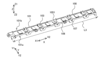
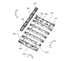
- FIG. 1 is a perspective view showing the configuration of a heat exchanger support device 100 according to Embodiment 1.
- FIG. 1 is an exploded perspective view showing the configuration of a heat exchanger support device 100 according to Embodiment 1.
- FIG. FIG. 2 is a perspective view showing the configuration of a base portion 101 provided in the heat exchanger support device 100 according to the first embodiment.
- FIG. 2 is a partially enlarged perspective view showing the configuration of a base portion 101 provided in the heat exchanger support device 100 according to the first embodiment.
- 1 is a schematic plan view schematically showing the configuration of a base portion 101 provided in a heat exchanger support device 100 according to Embodiment 1.
- FIG. 2 is a perspective cross-sectional view showing the configuration of a groove portion 103 provided in the heat exchanger support device 100 according to the first embodiment.
- FIG. 3 is a cross-sectional view showing the configuration of a groove portion 103 provided in the heat exchanger support device 100 according to the first embodiment.
- FIG. 4 is a perspective view showing the appearance of an outdoor unit 401 according to the first embodiment.
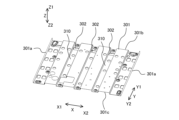
- FIG. 3 is a perspective view showing the configuration of a base 301 disposed inside a casing 300 of an outdoor unit 401 according to the first embodiment.
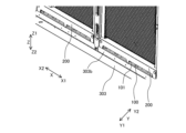
- FIG. 4 is a partially enlarged perspective view showing the structure of the lower part of the outdoor unit 401 according to the first embodiment.
- FIG. 4 is an exploded perspective view showing the structure of the lower part of the outdoor unit 401 according to the first embodiment.
- FIG. 3 is a perspective view showing the configuration of a base 301 and a heat exchanger support device 100 according to the first embodiment.
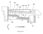
- FIG. 3 is a partial perspective view showing a first drainage path P1 in the heat exchanger support device 100 according to the first embodiment.
- FIG. 3 is a partial perspective view showing a second drainage path P2 in the heat exchanger support device 100 according to the first embodiment.
- FIG. 3 is a partial perspective view showing a second drainage path P2 in the heat exchanger support device 100 according to the first embodiment.
- FIG. 3 is a partial perspective view showing a third drainage path P3 in the heat exchanger support device 100 according to the first embodiment.
- FIG. 3 is a partial perspective view showing a third drainage path P3 in the heat exchanger support device 100 according to the first embodiment.
- FIG. 3 is a partial perspective view showing a third drainage path P3 in the heat exchanger support device 100 according to the first embodiment.
- FIG. 3 is a partial perspective view showing a third drainage path P3 in the heat exchanger support device 100 according to the first embodiment.
- FIG. 3 is a partial perspective view showing a fourth drainage path P4 in the heat exchanger support device 100 according to the first embodiment.
- FIG. 3 is a sectional view showing a fourth drainage path P4 in the heat exchanger support device 100 according to the first embodiment.
- FIG. 2 is a perspective view showing the configuration of a mounting portion 109 provided in the heat exchanger support device 100 according to the first embodiment.
- FIG. 3 is an exploded perspective view showing an example of the configuration of a heat exchanger 304 provided in the air conditioner 400 according to the first embodiment.
- the X direction is a direction that intersects with the Z direction, and indicates the longitudinal direction of the heat exchanger support device.
- the X direction is, for example, a horizontal direction.
- the X direction is sometimes referred to as the width direction of the heat exchanger.
- the Y direction is a direction that intersects the Z direction and the X direction, and indicates the lateral direction of the heat exchanger support device.
- the Y direction is, for example, a horizontal direction.
- the Y direction is sometimes called the depth direction of the heat exchanger.
- FIG. 1 is a perspective view showing the configuration of a heat exchanger support device 100 according to the first embodiment.
- FIG. 2 is an exploded perspective view showing the configuration of the heat exchanger support device 100 according to the first embodiment.
- FIG. 3 is a perspective view showing the configuration of the base 101 provided in the heat exchanger support device 100 according to the first embodiment.
- FIG. 4 is a partially enlarged perspective view showing the configuration of the base 101 provided in the heat exchanger support device 100 according to the first embodiment.
- FIG. 5 is a schematic plan view schematically showing the configuration of the base 101 provided in the heat exchanger support device 100 according to the first embodiment.
- the heat exchanger support device 100 supports the heat exchanger 304 (see FIG. 6) housed inside the outdoor unit 401 (see FIG. 8) of the air conditioner 400 (see FIG. 8). It is something.
- the heat exchanger support device 100 is made of resin.
- the heat exchanger support device 100 is provided below the side surface 300a of the casing 300 of the outdoor unit 401, as shown in FIG. 8, which will be described later. Therefore, in FIGS. 1 to 5, the Y1 direction of the Y direction is the direction from the inside of the casing 300 to the outside, and the Y2 direction of the Y direction is the direction from the outside of the casing 300 to the inside. Therefore, FIGS. 1 and 2 show the heat exchanger support device 100 viewed from the outside to the inside.
- FIGS. 3 and 4 show the heat exchanger support device 100 viewed from the inside to the outside.
- the heat exchanger support device 100 includes a heat exchanger 304 (see FIG. 6) housed inside a housing 300, a base 301 (described later) disposed below the heat exchanger 304 inside the housing 300, placed between.
- the heat exchanger support device 100 includes a base portion 101 having a main surface portion 102, a groove portion 103, a first drainage hole 104, and a water guide surface portion 105.
- the base 101 constitutes the main body of the heat exchanger support device 100.
- the base 101 has an elongated flat plate shape.
- the base 101 has an inner edge 101a that is one edge of the base 101 in the lateral direction, and an outer edge 101b that is the other edge of the base 101 in the lateral direction. Both the inner edge 101a and the outer edge 101b extend in the longitudinal direction of the base 101.
- the inner edge 101a is arranged on the inner space side of the casing 300 (see FIG. 8), and the outer edge 101b is It is arranged on the outside of the housing 300 (see FIG. 8).
- the base portion 101 has a flat main surface portion 102.
- the main surface portion 102 will be described later.
- the base 101 has a side flat portion 112, as shown in FIGS. 4 and 5.
- the side flat portion 112 is provided on the outer edge 101b and extends in the X direction.
- the side flat portion 112 is arranged horizontally so as to be parallel to the XY plane.
- the position in the Z direction of the side surface flat portion 112, that is, the height position may be the same as or different from the position in the Z direction of the upper end portion 106a of the side surface rib portion 106, which will be described later.
- the groove portion 103 is formed in the main surface portion 102 of the base portion 101.
- the groove portion 103 is a concave portion recessed downward from the main surface portion 102.
- the groove portion 103 extends in the lateral direction of the base portion 101 .
- the groove 103 has a first end 103a that is one end in the extending direction of the groove 103, and a second end 103b that is the other end in the extending direction.
- the first end 103a is arranged closer to the inner edge 101a of the base 101, and the second end 103b is arranged closer to the outer edge 101b of the base 101.
- a plurality of grooves 103 are arranged at intervals in the longitudinal direction of the base 101.
- the first drainage hole 104 is arranged at the first end 103a of the groove 103, as shown in FIG.
- the first drainage hole 104 is constituted by a through hole that penetrates through the thickness of the groove portion 103 .
- the first drainage hole 104 has, for example, a rectangular shape in plan view.
- the water guide surface portion 105 is formed inside the groove portion 103.
- the water guiding surface portion 105 descends stepwise or continuously from the second end portion 103b of the groove portion 103 toward the first drainage hole 104. That is, the water guiding surface portion 105 has a stepped portion 1051 that descends in stages from the second end portion 103b of the groove portion 103 toward the first drainage hole 104, as shown in FIG.
- the water guiding surface portion 105 has an inclined surface portion 1052 (see FIG. 7) that continuously descends from the second end portion 103b of the groove portion 103 toward the first drainage hole 104.
- the water guide surface portion 105 may have a configuration in which a stepped portion 1051 and an inclined surface portion 1052 are combined. That is, the stepped portion 1051 may have the inclined surface portion 1052.
- Embodiment 1 will be described using an example in which the stepped portion 1051 has an inclined surface portion 1052. This will be explained in detail below.
- FIG. 6 is a perspective sectional view showing the configuration of the groove portion 103 provided in the heat exchanger support device 100 according to the first embodiment.
- FIG. 6 shows a cross section of the groove portion 103 of the heat exchanger support device 100 when cut along an imaginary plane parallel to the YZ plane.
- a water guide surface portion 105 is formed inside the groove portion 103. Drain water generated and collected on the surface of the heat exchanger flows on the water guide surface section 105, as shown by the arrows in FIG.
- the water guiding surface portion 105 has a stepped portion 1051, as shown in FIG. In the example of FIG. 6, the stepped portion 1051 descends in two steps from the second end 103b of the groove portion 103 toward the first drainage hole 104. Note that the number of steps in the stepped portion 1051 is not limited to two steps, and may be determined as appropriate.
- FIG. 7 is a cross-sectional view showing the configuration of the groove portion 103 provided in the heat exchanger support device 100 according to the first embodiment.
- the water guide surface section 105 has an inclined surface section 1052.
- the slope portion 1052 continuously descends from the second end 103b of the groove portion 103 toward the first drainage hole 104.
- a step portion 1051 is provided on the inclined surface portion 1052, but the step portion may not be provided. That is, the inclined surface portion 1052 may be composed of one inclined surface.
- the inclined surface section 1052 includes a first inclined surface section 1052a, a second inclined surface section 1052b, and a third inclined surface section 1052c.
- the first inclined surface portion 1052a continuously descends at a first inclination angle ⁇ 1 as it advances from the second end portion 103b (see FIG. 5) toward the first end portion 103a (see FIG. 5).
- the second inclined surface portion 1052b is arranged closer to the first end portion 103a than the first inclined surface portion 1052a. That is, the second inclined surface portion 1052b is arranged on the first end portion 103a side with respect to the first inclined surface portion 1052a.
- the second inclined surface portion 1052b continuously descends at a second inclination angle ⁇ 2 as it advances from the second end portion 103b (see FIG. 5) toward the first end portion 103a (see FIG. 5).
- the third inclined surface section 1052c connects the first inclined surface section 1052a and the second inclined surface section 1052b.
- the third inclined surface portion 1052c continuously descends at a third inclination angle ⁇ 3 as it advances from the second end portion 103b (see FIG. 5) toward the first end portion 103a (see FIG. 5).
- the third inclination angle ⁇ 3 is larger than the first inclination angle ⁇ 1 and the second inclination angle ⁇ 2. That is, the third slope portion 1052c has the steepest slope shape.
- first inclination angle ⁇ 1 is equal to or larger than the second inclination angle ⁇ 2.
- first inclination angle ⁇ 1 is about 4 to 5 degrees
- second inclination angle ⁇ 2 is about 3 to 4 degrees
- third inclination angle ⁇ 3 is about 60 degrees. Note that these numerical values are merely examples, and the present invention is not limited to these numerical values.
- the step of the third slope section 1052c from the first slope section 1052a to the second slope section 1052b is the first step.
- a step 1052d from the second inclined surface portion 1052b to the first drainage hole 104 is a second step.
- the water guide surface section 105 is formed by combining the stepped section 1051 and the inclined surface section 1052. In this way, by providing one or more inclined surface portions 1052 in the stepped portion 1051, the flow rate of drain water becomes faster, and the drain water can be quickly drained.
- a steep third slope portion 1052c is provided at the center portion of the stepped portion 1051 in the Y direction. Therefore, even if the flow rate of the drain water at the first slope section 1052a becomes slow due to the influence of accumulated dust, it becomes faster again at the third slope section 1052c. Then, since the drain water continues to flow down toward the second inclined surface portion 1052b, it is possible to prevent the drain water from accumulating on the water guiding surface portion 105 without flowing.
- the heat exchanger support device 100 includes a side rib portion 106.
- the side rib portion 106 is provided on the inner edge 101a of the base portion 101, as shown in FIGS. 2 and 3.
- the side rib portion 106 has an elongated plate shape extending in the longitudinal direction of the inner edge 101a of the base portion 101.
- the side rib portion 106 is erected upward in the Z direction from the inner edge 101a.
- the side rib portion 106 has an uneven wavy shape when viewed from the side.
- the side rib portion 106 is a convex portion that protrudes downward, and the other portion of the side rib portion 106 is a long rectangular shape extending in the X direction. It has a shape.
- the side rib portion 106 includes a convex portion disposed corresponding to the position of the groove portion 103 in the longitudinal direction of the base portion 101, and a rectangular flat portion disposed between the convex portions. have.
- a notch 107 is formed in the side rib portion 106.
- the notch portion 107 is provided at the upper end portion 106a of the side rib portion 106.
- a plurality of notches 107 are arranged corresponding to the positions of grooves 103 in the longitudinal direction of base 101.
- the notch portion 107 is recessed downward in the Z direction from the upper end portion 106a of the side rib portion 106.
- the drain water normally flows along the first drainage path P1, through the water guide surface portion 105, and toward the first drainage hole 104.
- the first drainage hole 104 is arranged to correspond to a second drainage hole 302 formed in the base 301, which will be described later.
- the first drainage hole 104 is located directly above the second drainage hole 302 or is located inside the second drainage hole 302 and at the same height as the second drainage hole 302 . Therefore, the water guide surface portion 105 and the first drainage hole 104 form a first drainage path P1 through which drain water flows.
- the drain water is directly discharged to the outside of the casing 300 of the outdoor unit 401 through the water guide surface portion 105 and the first drainage hole 104 without contacting the base 301.
- the first drain hole 104 may be blocked by the frozen drain water.
- the drain water flows through the notch 107 formed in the side rib portion 106 after passing through the water guide surface portion 105, as shown by arrows in FIG. 15, which will be described later. Therefore, the water guide surface portion 105 and the notch portion 107 form a second drainage path P2 when the first drainage hole 104 is frozen.
- drain water passes through the water guide surface portion 105 and the notch portion 107 and flows toward the base 301 disposed inside the housing 300. Then, it flows from the base 301 toward the outside of the casing 300 of the outdoor unit 401 and is discharged.
- the heat exchanger support device 100 is provided with a heat exchanger protection wall 200, as shown in FIGS. 1 and 2.
- the heat exchanger protection wall 200 is provided on the outer edge 101b of the base 101 in the transverse direction.
- the heat exchanger protection wall 200 has an elongated plate shape extending in the longitudinal direction of the outer edge 101b of the base 101.
- the heat exchanger protection wall 200 is erected upward in the Z direction from the outer edge 101b. Therefore, the heat exchanger protection wall 200 and the side rib portion 106 are opposed to each other.
- the heat exchanger 304 has a heat exchanger header 307 connected to the lower ends of the plurality of heat exchanger tubes 305.
- Heat exchanger header 307 functions as a liquid or gas header.
- the heat exchanger protection wall 200 is disposed closer to the outside of the casing 300 (see FIG. 8) of the outdoor unit 401 (see FIG. 8) than the heat exchanger header 307. That is, as shown in FIG. 6, the heat exchanger protection wall 200 is arranged on the outside of the heat exchanger header 307 so as to cover the heat exchanger header 307.
- the heat exchanger protection wall 200 and the heat exchanger header 307 are not in contact with each other and are spaced apart from each other with a gap therebetween.
- the heat exchanger protection wall 200 has an upper bent portion 202 at the upper end.
- the upper bent portion 202 is inclined toward the heat exchanger 304 from the Z direction toward the tip.
- the upper bent portion 202 is bent along the outer shape of the upper end of the heat exchanger header 307, and covers the upper end of the heat exchanger header 307 from above.
- the upper bent portion 202 and the upper end of the heat exchanger header 307 are not in contact with each other and are spaced apart from each other with a gap therebetween.
- the heat exchanger protection wall 200 is arranged to cover the heat exchanger header 307. Therefore, the heat exchanger protection wall 200 prevents the heat exchanger header 307 from being damaged due to foreign objects such as pebbles colliding with the heat exchanger header 307.
- the heat exchanger protection wall 200 is disposed outside the heat exchanger header 307, it also functions as a windbreak plate for the heat exchanger header 307. Therefore, the heat exchanger protection wall 200 can prevent the heat exchanger header 307 from freezing due to wind hitting the heat exchanger header 307. Furthermore, by providing the heat exchanger protection wall 200, outside air is taken into the outdoor unit 401 from the side surface 300a of the housing 300 for heat exchange in the heat exchanger 304. At this time, if the heat exchanger protection wall 200 is not provided, outside air will be sucked in from below the housing 300 as well. Since this outside air is not used for heat exchange, the heat exchange efficiency of the heat exchanger 304 decreases. In the first embodiment, by providing the heat exchanger protection wall 200, it is possible to prevent a decrease in heat exchange efficiency. Furthermore, the heat exchanger protection wall 200 can also prevent insects from entering the housing 300.
- the heat exchanger protection wall 200 has a drain gate 201, as shown in FIG.
- Drain gate 201 is provided at the lower end of heat exchanger protection wall 200.
- the drain gate 201 is formed to be recessed upward in the Z direction from the lower end 200a of the heat exchanger protection wall 200.
- the drain gate 201 is an elongated slit-shaped gap whose longitudinal direction extends in the X direction.
- the drain gate 201 forms a fourth drain path P4, which will be described later, for draining drain water.
- the drain gate 201 is formed in a size that allows water to pass through and prevents pebbles, wind, insects, etc. from entering.
- the heat exchanger protection wall 200 is made of resin.
- the heat exchanger protection wall 200 may be integrally molded with the base 101 and the like as a part of the heat exchanger support device 100.
- the heat exchanger protection wall 200 may be configured separately from the base 101 and the like and may be attached to the base 101, as shown in the exploded perspective view of FIG.
- the base portion 101, the main surface portion 102, the groove portion 103, the first drainage hole 104, the water guide surface portion 105, the side rib portion 106, the notch portion 107, and the convex portion 108 described below are integrally molded from resin.
- FIG. 8 is a perspective view showing the external appearance of the outdoor unit 401 according to the first embodiment.
- FIG. 9 is a perspective view showing the configuration of the base 301 disposed inside the casing 300 of the outdoor unit 401 according to the first embodiment.
- FIG. 10 is a partially enlarged perspective view showing the structure of the lower part of the outdoor unit 401 according to the first embodiment.
- FIG. 11 is an exploded perspective view showing the structure of the lower part of the outdoor unit 401 according to the first embodiment.
- FIG. 12 is a perspective view showing the configuration of the base 301 and the heat exchanger support device 100 according to the first embodiment.
- the outdoor unit 401 of the air conditioner 400 includes a housing 300.
- the housing 300 has, for example, a rectangular parallelepiped shape.
- the housing 300 has four side surfaces 300a and a top surface 300b.
- the heat exchanger support device 100 is attached below at least one side surface 300a of the four side surfaces 300a of the housing 300. Note that the side surface 300a to which the heat exchanger support device 100 is attached is sometimes referred to as the front surface of the outdoor unit 401.
- a blower fan 308 is provided above inside the housing 300.
- the outdoor unit 401 includes two heat exchangers 304 (see FIG. 6) and two blower fans 308, but is not limited thereto. Outdoor unit 401 may have one heat exchanger 304 and one blower fan 308. Note that when two heat exchangers 304 are housed in the housing 300, these heat exchangers 304 are arranged side by side in the X direction. Similarly, when two blower fans 308 are housed in the housing 300, the blower fans 308 are arranged side by side in the X direction, as shown in FIG. As the blower fan 308 is driven to rotate, outside air is sucked into the housing 300 from the side surface 300a of the housing 300. The heat exchanger 304 exchanges heat between the drawn outside air and the refrigerant flowing inside the heat exchanger tubes 305 . The outside air that has undergone heat exchange with the refrigerant is exhausted to the outside from the top surface 300b of the housing 300.
- a heat exchanger 304 (see FIG. 6) is housed inside the casing 300.
- the heat exchanger 304 includes heat exchanger tubes 305 and fins 306 (see FIG. 22).
- the heat exchanger 304 is, for example, a fin-and-tube heat exchanger.
- FIG. 22 is an exploded perspective view showing an example of the configuration of the heat exchanger 304 provided in the air conditioner 400 according to the first embodiment.
- the heat exchanger tube 305 has a tube axis extending in the vertical direction, that is, in the Z direction.
- Heat exchanger tube 305 is, for example, a flat tube.
- a plurality of heat exchanger tubes 305 are arranged at intervals in the X direction.
- the flat surfaces of the heat exchanger tubes 305 are arranged parallel to the YZ plane, and the flat surfaces of adjacent heat exchanger tubes 305 face each other. Furthermore, in the examples shown in FIGS. 6 and 22, the heat exchanger tubes 305 are arranged in two rows in the Y direction. A heat exchanger header 307 is provided for each row. Note that the number of rows of heat exchanger tubes 305 is not limited to two rows. That is, the number of rows of heat exchanger tubes 305 may be any number greater than or equal to one. Further, the fins 306 are, for example, corrugated fins, but are not limited thereto. When the fins 306 are corrugated fins, they are arranged between adjacent heat exchanger tubes 305, as shown in FIG.
- the fins 306 are flat fins, the fins 306 are arranged at intervals in a direction intersecting the tube axis direction of the heat transfer tube 305.
- the heat exchanger tubes 305 are arranged to penetrate through the fins 306. Further, as shown in FIG. 6, a heat exchanger header 307 is connected to the lower end portion of the heat exchanger tube 305.
- the heat exchanger support device 100 is attached below the side surface 300a of the housing 300, as shown in FIG. In the example of FIG. 8, one heat exchanger support device 100 is attached to the housing 300, but the present invention is not limited to this. That is, since two heat exchangers 304 are provided within the casing 300, two heat exchanger support devices 100 may be attached to the casing 300 in correspondence with those heat exchangers 304. .
- the heat exchanger support device 100 has a base 101 disposed inside a casing 300. An inner edge 101a (see FIG. 1) of the base 101 is arranged in the internal space of the housing 300. The outer edge 101b (see FIG.
- the base 101 is also arranged in the internal space of the casing 300, but is arranged closer to the outside of the casing 300 than the inner edge 101a.
- the inner edge 101a and the outer edge 101b are opposed to each other, as shown in FIG.
- the heat exchanger protection wall 200 is arranged in the same plane as the side surface 300a of the housing 300 and is exposed to the outside.
- a base leg 303 is arranged below the housing 300, as shown in FIG.
- the base leg 303 is a support member that supports the base 301 (see FIG. 9) arranged below the internal space of the housing 300.
- the main body 303a of the base leg 303 has an angular U-shape when viewed from the side, and is open toward the outside of the housing 300.
- a mounting portion 303b is provided on the upper edge of the main body 303a of the base leg 303.
- the attachment portion 303b extends upward in the Z direction from the upper edge of the main body 303a.
- a screw hole is formed in the mounting portion 303b.
- the heat exchanger protection wall 200 is fixed to the base leg 303, as shown in FIG. Furthermore, a leg cover 303c (see FIG. 18) is provided at the opening of the angular U-shaped main body 303a, if necessary.
- the leg cover 303c can prevent foreign objects such as pebbles from entering the base leg 303.
- the longitudinal direction of the base 101 of the heat exchanger support device 100 is arranged to be parallel to the width direction of the heat exchanger 304.
- the width direction of the heat exchanger 304 is the stacking direction of the heat exchanger tubes 305, and is the X direction.
- the width direction of the base portion 101 of the heat exchanger support device 100 is arranged to be parallel to the depth direction of the heat exchanger 304.
- the depth direction of the heat exchanger 304 is a direction intersecting the stacking direction of the heat exchanger tubes 305, and specifically, the Y direction.
- the length of the installation area 309 of the heat exchanger 304 in the Y direction is defined as "length L1", and as shown in FIG. Let the length be "length L2".
- the length L2 of the base 101 in the Y direction is longer than the length L1 of the installation area 309 of the heat exchanger 304 in the Y direction.
- the length L2 of the base 101 of the heat exchanger support device 100 in the transverse direction is longer than the length L1, which is the total length of the heat exchanger 304 in the depth direction.
- the installation area 309 of the heat exchanger 304 is an area where the heat exchanger tubes 305 and the heat exchanger header 307 of the heat exchanger 304 are installed.
- the length L3 (see FIG. 3) in the longitudinal direction of the base 101 of the heat exchanger support device 100 is the length L4 (see FIG. 3), which is the total length in the X direction of the installation area 309 (see FIG. 22) or longer than length L4.
- the length L3 in the longitudinal direction of the base 101 of the heat exchanger support device 100 is longer than the length L4, which is the entire length of the heat exchanger 304 in the width direction.
- two heat exchangers 304 are arranged within the casing 300. In this way, when there are a plurality of heat exchangers 304, the length L4 in the X direction of the installation area 309 (see FIG. 22) of the heat exchanger 304 is determined by the length L4 in the X direction of the installation area 309 (see FIG. This is the total length of all the heat exchangers 304 in the X direction.
- the base 101 is arranged to cover the entire lower surface of the heat exchanger 304 including the heat exchanger header 307. Therefore, the base portion 101 can receive all of the drain water flowing down along the surface of the heat transfer tube 305.
- a base 301 is arranged below the internal space of the casing 300 of the outdoor unit 401.
- the base 301 is placed on base legs 303, as shown in FIG.
- a base 101 of the heat exchanger support device 100 is arranged above the base 301 . Therefore, the base 101 is arranged between the heat exchanger header 307 provided in the heat exchanger 304 and the base 301 in the Z direction.
- the heat exchanger support device 100 is made of resin.
- the heat exchanger header 307 is made of aluminum
- the base 301 is made of steel. Therefore, when the heat exchanger header 307 and the base 301 are in contact, dissimilar metal corrosion occurs.
- Dissimilar metal contact corrosion is a phenomenon in which corrosion occurs when metals with a potential difference come into contact with each other and electrons are exchanged between the dissimilar metals. Therefore, in the first embodiment, a heat exchanger support device 100 made of resin is disposed between the heat exchanger header 307 and the base 301. Thereby, occurrence of dissimilar metal corrosion can be suppressed.
- the base 301 has a rectangular shape in plan view, as shown in FIGS. 9 and 12.
- the base 301 is made of a corrugated steel plate. By processing the base into a corrugated plate shape, it is possible to make it easier for drain water to flow on the base, and to give the base strength against bending and deflection deformation.
- the base 301 has rising portions 301a at both ends in the X direction.
- the rising portion 301a is formed by bending the side edges of both ends of the base 301 in the X direction upward in the Z direction.
- the base 301 also includes a second drain hole 302 that drains drain water generated by melting frost during the defrost operation to the outside of the housing 300, and a drain groove 310 that guides the drain water to the second drain hole 302.
- the base 301 has a front side edge 301b that constitutes one side edge in the Y direction, and a back side edge 301c that constitutes the other side edge in the Y direction.
- the second drainage hole 302 is formed closer to the front edge 301b with respect to the center in the Y direction.
- the second drainage hole 302 is arranged near the front side edge 301b.
- a plurality of second drainage holes 302 are arranged at intervals in the X direction.
- the drain groove 310 extends in the Y direction.
- the drain groove 310 is arranged corresponding to the second drain hole 302.
- the first drainage hole 104 formed in the heat exchanger support device 100 is arranged directly above the second drainage hole 302 of the base 301.
- the first drainage hole 104 is arranged inside the second drainage hole 302 of the base 301 and at the same height as the second drainage hole 302, as shown in FIG. Therefore, the first drain hole 104 formed in the heat exchanger support device 100 is arranged to correspond to the position of the second drain hole 302 of the base 301.
- the opening area of the first drainage hole 104 is smaller than the opening area of the second drainage hole 302. Therefore, the first drain hole 104 can be arranged to fit inside the second drain hole 302 when viewed from above. As a result, as shown by the arrow in FIG. Water is drained directly to the outside of the casing 300 from the drain hole 104 .
- the resin first drain hole 104 directly above or inside the second drain hole 302 of the base 301, drain water can flow from the first drain hole 104 without coming into contact with the base 301. , the water can be directly drained to the outside of the housing 300. As a result, it is possible to prevent drain water from accumulating on the base 301. Therefore, the base 301 will not be covered with ice, and the second drainage hole 302 will not be blocked by ice. Therefore, in the first embodiment, since it is possible to prevent ice from growing to the bottom of the heat exchanger unlike in the conventional device, the fins 306, heat exchanger header 307, and heat transfer tubes 305 are protected from damage caused by freezing. can do.
- FIG. 13 is a partial perspective view showing the first drainage path P1 in the heat exchanger support device 100 according to the first embodiment.
- FIG. 13 shows a cross section of the water guide surface portion 105 of the heat exchanger support device 100, taken along a virtual plane parallel to the XZ plane. Therefore, in FIG. 13, the side rib portion 106 is not illustrated.
- FIG. 13 shows a state in which the heat exchanger support device 100 is viewed from the internal space side of the housing 300. Drain water first flows down along the surface of the heat transfer tube 305 whose tube axis direction extends in the Z direction. The drain water is then received at the base 101 of the heat exchanger support device 100.
- the base portion 101 is provided with the main surface portion 102 as described above.
- the main surface section 102 includes a first main surface section 102a (see FIG. 4) and a second main surface section 102b (see FIG. 4), as will be explained in detail with reference to FIG. 4 in the explanation of the second drainage path P2 described later. It has The first main surface portion 102a and the second main surface portion 102b are each provided with an inclination that becomes lower toward the groove portion 103. Therefore, the drain water received by the main surface 102 of the base 101 flows toward the groove 103 in the X direction due to the inclination of the first main surface 102a and the second main surface 102b in the X direction.
- the drain water that has flowed down into the groove 103 flows through the water guide surface 105 disposed within the groove 103 and reaches the first drain hole 104, as shown in FIGS. 6 and 13. Then, the drain water is directly drained to the outside of the casing 300 from the first drain hole 104 without contacting the second drain hole 302 and the base 301.
- FIG. 14 is a partial perspective view showing the second drainage path P2 in the heat exchanger support device 100 according to the first embodiment.
- FIG. 14 shows a state in which the heat exchanger support device 100 is viewed from the internal space side of the housing 300.
- FIG. 15 is a partial perspective view showing the second drainage path P2 in the heat exchanger support device 100 according to the first embodiment.
- the second drainage path P2 is a drainage path when the first drainage hole 104 is frozen.
- the drain water flows through the main surface 102, the water guide surface 105, and the notch 107 of the heat exchanger support device 100, as shown by the arrows in FIGS. 14 and 15. flows. This will be explained in detail below.
- the main surface portion 102 will be explained using FIG. 4 mentioned above.
- the main surface section 102 provided on the base 101 of the heat exchanger support device 100 has a first main surface section 102a and a second main surface section 102b.
- the first main surface section 102a and the second main surface section 102b are arranged at both ends of the groove section 103 in the longitudinal direction of the base section 101, as shown in FIG.
- the first main surface portion 102a and the second main surface portion 102b are each inclined downward toward the groove portion 103 in the longitudinal direction of the base portion 101, as shown in FIG.
- the main surface portion 102 is provided with a convex portion 108.
- the heat exchanger header 307 is placed on the convex portion 108 and supports the heat exchanger header 307.
- the main surface 108a of the convex portion 108 is not inclined and is installed horizontally.
- the first main surface portion 102a is arranged between the installation position of the convex portion 108 and the installation position of the groove portion 103. More specifically, the starting point of the first main surface portion 102a corresponds to the center of the convex portion 108 in the X direction. Further, the end point of the first main surface portion 102a is one end of the groove portion 103 in the X direction. The first main surface portion 102a is inclined downward from the starting point toward the ending point.
- the second main surface portion 102b is arranged between the installation position of the convex portion 108 and the installation position of the groove portion 103. More specifically, the starting point of the second main surface portion 102b corresponds to the center of the convex portion 108 in the X direction. Further, the end point of the second main surface portion 102b is the other end of the groove portion 103 in the X direction. The second main surface portion 102b is inclined downward from the starting point toward the ending point.
- the drain water received by the main surface section 102 flows toward the groove section 103 in the X direction due to the inclination of the first main surface section 102a and the second main surface section 102b in the X direction.
- the drain water that has flowed down into the groove portion 103 passes through the water guide surface portion 105 and flows from the notch portion 107 toward the base 301.
- each of the first main surface portion 102a and the second main surface portion 102b is inclined not only in the X direction but also in the Y direction. That is, to explain the second main surface part 102b as an example using FIG. , sloping downward.
- the first main surface portion 102a is inclined downward along the direction from the second end portion 103b of the groove portion 103 to the first end portion 103a.
- the drain water received by the main surface section 102 flows in the Y direction toward the first end 103a of the groove section 103 due to the inclination of the first main surface section 102a and the second main surface section 102b in the Y direction.
- the drain water that has flowed down into the groove portion 103 passes through the water guide surface portion 105 and flows from the notch portion 107 toward the base 301.
- first main surface portion 102a and the second main surface portion 102b are provided with an inclination in the X direction and an inclination in the Y direction, drain water is efficiently drained to the first drain hole 104 in the groove portion 103. It is designed to flow towards.
- the drain water received by the main surface section 102 of the heat exchanger support device 100 flows through the water guide surface section 105 and the notch section 107.
- FIG. 16 is a partial perspective view showing the third drainage path P3 in the heat exchanger support device 100 according to the first embodiment.
- FIG. 16 shows the heat exchanger support device 100 viewed from the outside of the housing 300.
- FIG. 17 is a partial perspective view showing the third drainage path P3 in the heat exchanger support device 100 according to the first embodiment.
- FIG. 18 is a partial perspective view showing the third drainage path P3 in the heat exchanger support device 100 according to the first embodiment.
- the third drainage path P3 is a drainage path when the first drainage hole 104 and the notch 107 are frozen.
- the drain water passes through the water guide surface portion 105 and then exceeds the upper end portion 106a of the side rib portion 106, as shown by the arrows in FIGS. 16 to 18. flows. This will be explained in detail below.
- the upper end portion 106a of the side rib portion 106 is located at a position lower than the installation height at which the heat exchanger 304 is installed. More specifically, as shown in FIG. 18, the upper end 106a of the side rib portion 106 is located at a position lower than the installation height at which the heat exchanger header 307 of the heat exchanger 304 is installed. Therefore, as shown by the arrows in FIGS. 16 and 17, in the third drainage path P3, after passing through the water guiding surface section 105, the drain water flows over the upper end 106a of the side rib section 106 and into the interior of the casing 300. The water flows toward the base 301 located at the base 301 .
- FIG. 19 is a partial perspective view showing the fourth drainage path P4 in the heat exchanger support device 100 according to the first embodiment.
- FIG. 20 is a sectional view showing the fourth drainage path P4 in the heat exchanger support device 100 according to the first embodiment.
- the fourth drainage path P4 is a drainage path when the first drainage hole 104 and the notch 107 are frozen.
- drain water passes through the main surface 102 of the base 101 and the drain gate 201 of the heat exchanger protection wall 200, as shown by the arrows in FIGS. 19 and 20. and flows toward the outside of the casing 300. This will be explained in detail below.
- the drain gate 201 is provided at the lower end of the heat exchanger protection wall 200. As shown in FIG. 2, the drain gate 201 is an elongated slit-shaped gap. The drain gate 201 is formed to be recessed upward from the lower end 200a of the heat exchanger protection wall 200.
- FIG. 21 is a perspective view showing the configuration of the mounting portion 109 provided in the heat exchanger support device 100 according to the first embodiment. As shown in FIG. 21, the heat exchanger support device 100 has a plate-shaped attachment portion 109.
- the mounting portion 109 is fixed to the side rib portion 106.
- the attachment portion 109 has a rectangular shape in plan view.
- the attachment portion 109 extends in a direction intersecting the direction in which the side rib portion 106 is erected. That is, the attachment portion 109 extends in the Y direction intersecting the Z direction.
- the attachment portion 109 projects from the side rib portion 106 in a direction away from the base portion 101 .
- the mounting portion 109 has a screw hole 110 that passes through the thickness of the mounting portion 109 .
- the mounting portion 109 is fixed to the base 301 with a screw inserted into a screw hole 110. Note that the fixture inserted into the screw hole 110 may be a bolt and a nut.
- the mounting portion 109 is provided with a plate-shaped reinforcing rib 111.
- the reinforcing ribs 111 are arranged at both ends of the attachment part 109 in the longitudinal direction of the base part 101.
- the reinforcing ribs 111 are erected upward in the Z direction from both ends of the attachment portion 109 in the X direction.
- the reinforcing rib 111 has a triangular or pentagonal shape when viewed from the side.
- An end portion 111a of the reinforcing rib 111 extending in the vertical direction is fixed to the side rib portion 106.
- the first drain hole 104 may have a safety guard 113 that prevents foreign matter from entering the first drain hole 104, as shown in FIG. 17.
- the foreign object here is, for example, a user's finger.
- the safety guard 113 includes a plurality of rod-shaped members 113a fixed to both ends of the first drainage hole 104 in the Y direction.
- the rod-shaped member 113a extends in the Y direction.
- the rod-shaped member 113a has, for example, a prismatic shape, but may also have a cylindrical shape.
- a plurality of rod-shaped members 113a are arranged at intervals in the X direction. Therefore, the safety guard 113 has a flat plate shape shaped like a fence.
- a heat exchanger 304 is arranged above the first drainage hole 104. More specifically, a heat exchanger header 307 of the heat exchanger 304 is arranged above the first drain hole 104 . Heat exchanger header 307 may also function as a gas header, in which case it will be at significantly higher temperatures. Therefore, a safety guard 113 may be provided in the first drain hole 104 to prevent the user's fingers from entering the first drain hole 104 from the outside. In that case, the user's fingers will be blocked by the safety guard 113 and will not enter the first drainage hole 104, so safety is ensured.
- FIG. 17 shows a case where the safety guard 113 has a flat plate shape formed like a fence
- the safety guard 113 may have, for example, a flat plate shape formed in a lattice shape.
- a second rod-shaped member (not shown) is provided between two adjacent rod-shaped members 113a.
- the second rod-shaped member extends in the X direction from one of the two adjacent rod-shaped members 113a toward the other.
- a plurality of second rod-shaped members are installed at intervals in the Y direction.
- the second rod-shaped member has, for example, a prismatic shape, but may also have a cylindrical shape.
- the rod-shaped member 113a and the second rod-shaped member are integrally molded from resin.
- the safety guard 113 has a flat plate shape in the form of a fence or a grid. Furthermore, the safety guard 113 is made of a heat-resistant resin such as foamed resin.
- the safety guard 113 may be integrally molded from resin together with the base 101 and the like, but it may also be constructed separately from the base 101 and the like and attached to the inside of the first drain hole 104.
- the heat exchanger support device 100 includes the main surface portion 102, the groove portion 103, the water guide surface portion 105, and the first drain hole 104. Therefore, the heat exchanger support device 100 causes the drain water received by the main surface portion 102 to flow down on the water guiding surface portion 105 in the groove portion 103 and discharged from the first drain hole 104 to the outside of the casing 300. Since the first drain hole 104 is located directly above or inside the second drain hole 302 provided in the base 301, the drain water is drained to the outside of the casing 300 without coming into contact with the base 301. Ru. Thereby, by efficiently draining the drain water from the heat exchanger 304, it is possible to prevent the heat exchanger 304 from being damaged by ice.
- the heat exchanger support device 100 is made of resin.
- the heat exchanger support device 100 is arranged between a heat exchanger header 307 made of aluminum and a base 301 made of steel. Therefore, the heat exchanger support device 100 can suppress the occurrence of dissimilar metal corrosion.
- the second drain path P2 when the first drain hole 104 freezes, the second drain path P2 is provided for draining the drain water by flowing it down toward the inside of the casing 300.
- the second drainage path P2 includes a notch 107 formed in the side rib portion 106 of the heat exchanger support device 100.
- a third drainage path P3 and a fourth drainage path P4 are provided for draining drain water.
- the third drainage path P3 is configured by arranging the upper end portion 106a of the side rib portion 106 lower than the installation height of the heat exchanger 304.
- the fourth drainage path P4 is configured by providing a drainage gate 201 on the heat exchanger protection wall 200.
- the heat exchanger support device 100 has the notch 107 for draining inside the machine, the side rib portion 106 lower than the installation height of the heat exchanger 304, and the drain gate 201. Multiple drainage routes are secured in case of ice. In this way, by securing a drainage path during freezing, the resistance of the outdoor unit 401 to freezing is improved.
- the heat exchanger support device 100 is provided with a heat exchanger protection wall 200.
- Heat exchanger protection wall 200 is arranged outside heat exchanger header 307 so as to cover heat exchanger header 307 . Therefore, the heat exchanger protection wall 200 can protect the heat exchanger header 307 from damage caused by pebbles and the like, and can prevent the heat exchanger header 307 from freezing due to wind.
- Heat exchanger support device 101 base, 101a inner edge, 101b outer edge, 102 main surface, 102a first main surface, 102b second main surface, 103 groove, 103a first end, 103b second end , 104 First drainage hole, 105 Water guide surface part, 106 Side rib part, 106a Upper end part, 107 Notch part, 108 Convex part, 108a Main surface, 109 Mounting part, 110 Screw hole, 111 Reinforcement rib, 111a End part, 112 Side flat part, 113 Safety guard, 113a Rod member, 200 Heat exchanger protection wall, 200a Lower end, 201 Drain gate, 202 Upper bent part, 300 Housing, 300a Side, 300b Top surface, 301 Base, 301a Rising part, 301b Front side edge, 301c Back side edge, 302 Second drain hole, 303 Base leg, 303a Main body, 303b Mounting part, 303c Leg cover, 304 Heat exchanger, 305 Heat exchanger tube, 306 Fin, 307 Heat exchanger header
Landscapes
- Engineering & Computer Science (AREA)
- Mechanical Engineering (AREA)
- General Engineering & Computer Science (AREA)
- Chemical & Material Sciences (AREA)
- Combustion & Propulsion (AREA)
- Physics & Mathematics (AREA)
- Thermal Sciences (AREA)
- Transportation (AREA)
- Other Air-Conditioning Systems (AREA)
- Air Filters, Heat-Exchange Apparatuses, And Housings Of Air-Conditioning Units (AREA)
Priority Applications (5)
| Application Number | Priority Date | Filing Date | Title |
|---|---|---|---|
| US18/838,473 US20250155158A1 (en) | 2022-04-25 | 2022-04-25 | Heat exchanger support device |
| EP22940048.6A EP4517246A4 (en) | 2022-04-25 | 2022-04-25 | Heat exchanger support device |
| PCT/JP2022/018710 WO2023209767A1 (ja) | 2022-04-25 | 2022-04-25 | 熱交換器支え装置 |
| CN202280092482.0A CN119013517A (zh) | 2022-04-25 | 2022-04-25 | 热交换器支承装置 |
| JP2024517623A JP7809201B2 (ja) | 2022-04-25 | 2022-04-25 | 熱交換器支え装置 |
Applications Claiming Priority (1)
| Application Number | Priority Date | Filing Date | Title |
|---|---|---|---|
| PCT/JP2022/018710 WO2023209767A1 (ja) | 2022-04-25 | 2022-04-25 | 熱交換器支え装置 |
Publications (1)
| Publication Number | Publication Date |
|---|---|
| WO2023209767A1 true WO2023209767A1 (ja) | 2023-11-02 |
Family
ID=88518169
Family Applications (1)
| Application Number | Title | Priority Date | Filing Date |
|---|---|---|---|
| PCT/JP2022/018710 Ceased WO2023209767A1 (ja) | 2022-04-25 | 2022-04-25 | 熱交換器支え装置 |
Country Status (5)
| Country | Link |
|---|---|
| US (1) | US20250155158A1 (https=) |
| EP (1) | EP4517246A4 (https=) |
| JP (1) | JP7809201B2 (https=) |
| CN (1) | CN119013517A (https=) |
| WO (1) | WO2023209767A1 (https=) |
Citations (8)
| Publication number | Priority date | Publication date | Assignee | Title |
|---|---|---|---|---|
| JPS58111863U (ja) * | 1982-01-25 | 1983-07-30 | 三菱電機株式会社 | 空気調和機 |
| US20050034471A1 (en) * | 2003-08-14 | 2005-02-17 | Samsung Electronics Co., Ltd. | Outdoor unit for air conditioner |
| JP2010038486A (ja) * | 2008-08-07 | 2010-02-18 | Daikin Ind Ltd | 分離型空気調和機の室外ユニット |
| JP2010151387A (ja) * | 2008-12-25 | 2010-07-08 | Mitsubishi Electric Corp | 空気調和機の室外機 |
| WO2013088713A1 (ja) | 2011-12-12 | 2013-06-20 | ダイキン工業株式会社 | ヒータ及びそれを備えた冷凍装置の室外ユニット |
| JP2018128231A (ja) * | 2017-02-10 | 2018-08-16 | 株式会社前川製作所 | 熱交換ユニット及びヒートポンプユニット |
| JP2018151103A (ja) * | 2017-03-10 | 2018-09-27 | 日立ジョンソンコントロールズ空調株式会社 | 空気調和機の室外機 |
| JP2019132543A (ja) * | 2018-01-31 | 2019-08-08 | ダイキン工業株式会社 | 空気調和装置の室外機 |
Family Cites Families (4)
| Publication number | Priority date | Publication date | Assignee | Title |
|---|---|---|---|---|
| JPS5546901Y2 (https=) * | 1976-05-07 | 1980-11-04 | ||
| JPS5678917U (https=) * | 1979-11-22 | 1981-06-26 | ||
| WO2008084277A1 (en) * | 2007-01-10 | 2008-07-17 | Carrier Corporation | Condensate removal system |
| US10208968B2 (en) * | 2014-12-26 | 2019-02-19 | Mitsubishi Electric Corporation | Outdoor unit |
-
2022
- 2022-04-25 JP JP2024517623A patent/JP7809201B2/ja active Active
- 2022-04-25 US US18/838,473 patent/US20250155158A1/en active Pending
- 2022-04-25 EP EP22940048.6A patent/EP4517246A4/en active Pending
- 2022-04-25 CN CN202280092482.0A patent/CN119013517A/zh active Pending
- 2022-04-25 WO PCT/JP2022/018710 patent/WO2023209767A1/ja not_active Ceased
Patent Citations (8)
| Publication number | Priority date | Publication date | Assignee | Title |
|---|---|---|---|---|
| JPS58111863U (ja) * | 1982-01-25 | 1983-07-30 | 三菱電機株式会社 | 空気調和機 |
| US20050034471A1 (en) * | 2003-08-14 | 2005-02-17 | Samsung Electronics Co., Ltd. | Outdoor unit for air conditioner |
| JP2010038486A (ja) * | 2008-08-07 | 2010-02-18 | Daikin Ind Ltd | 分離型空気調和機の室外ユニット |
| JP2010151387A (ja) * | 2008-12-25 | 2010-07-08 | Mitsubishi Electric Corp | 空気調和機の室外機 |
| WO2013088713A1 (ja) | 2011-12-12 | 2013-06-20 | ダイキン工業株式会社 | ヒータ及びそれを備えた冷凍装置の室外ユニット |
| JP2018128231A (ja) * | 2017-02-10 | 2018-08-16 | 株式会社前川製作所 | 熱交換ユニット及びヒートポンプユニット |
| JP2018151103A (ja) * | 2017-03-10 | 2018-09-27 | 日立ジョンソンコントロールズ空調株式会社 | 空気調和機の室外機 |
| JP2019132543A (ja) * | 2018-01-31 | 2019-08-08 | ダイキン工業株式会社 | 空気調和装置の室外機 |
Non-Patent Citations (1)
| Title |
|---|
| See also references of EP4517246A4 |
Also Published As
| Publication number | Publication date |
|---|---|
| JP7809201B2 (ja) | 2026-01-30 |
| EP4517246A4 (en) | 2025-06-18 |
| US20250155158A1 (en) | 2025-05-15 |
| EP4517246A1 (en) | 2025-03-05 |
| CN119013517A (zh) | 2024-11-22 |
| JPWO2023209767A1 (https=) | 2023-11-02 |
Similar Documents
| Publication | Publication Date | Title |
|---|---|---|
| CN103314269B (zh) | 热交换器及空调机 | |
| KR101451056B1 (ko) | 열교환기 및 공기 조화기 | |
| KR100472214B1 (ko) | 공기조화기의 실외유닛 | |
| WO2001051859A1 (en) | Outdoor unit of air conditioner | |
| CN103261828B (zh) | 热交换器和安装有该热交换器的空气调节机 | |
| CN110036244B (zh) | 空调机的室外机和具备该室外机的空调机 | |
| EP2159497B1 (en) | Outdoor unit of conditioning apparatus | |
| JPWO2018011939A1 (ja) | 空気調和機の室外機 | |
| WO2023209767A1 (ja) | 熱交換器支え装置 | |
| JP2008202889A (ja) | エンジン駆動式ヒートポンプ | |
| JP6932262B2 (ja) | 熱交換器、熱交換器ユニット、及び冷凍サイクル装置 | |
| JP6448948B2 (ja) | 熱交換器およびそれを用いた空気調和機用室外機 | |
| WO2024023908A1 (ja) | 熱交換器および冷凍サイクル装置 | |
| JP7353483B2 (ja) | 熱交換器及び該熱交換器を備えた空気調和機 | |
| JP7031019B2 (ja) | 空気調和機の室外機 | |
| CN111670326B (zh) | 空调装置的室外机 | |
| JP5591218B2 (ja) | 空気調和機の室外ユニット | |
| JP6131460B2 (ja) | フィン付き熱交換器 | |
| JP6925332B2 (ja) | 空気調和装置の室外機 | |
| JP5985952B2 (ja) | 空気調和機の室外ユニット | |
| JP2010054115A (ja) | エバポレータ | |
| US20250102183A1 (en) | Air handling unit comprising drain cover | |
| JPH09159389A (ja) | フィン付熱交換器 | |
| JP6118165B2 (ja) | 無落雪屋根構造 | |
| JPWO2014199514A1 (ja) | 空気調和機の室外機、及び空気調和機の室外機の製造方法 |
Legal Events
| Date | Code | Title | Description |
|---|---|---|---|
| 121 | Ep: the epo has been informed by wipo that ep was designated in this application |
Ref document number: 22940048 Country of ref document: EP Kind code of ref document: A1 |
|
| ENP | Entry into the national phase |
Ref document number: 2024517623 Country of ref document: JP Kind code of ref document: A |
|
| WWE | Wipo information: entry into national phase |
Ref document number: 18838473 Country of ref document: US |
|
| WWE | Wipo information: entry into national phase |
Ref document number: 202280092482.0 Country of ref document: CN |
|
| WWE | Wipo information: entry into national phase |
Ref document number: 2022940048 Country of ref document: EP |
|
| NENP | Non-entry into the national phase |
Ref country code: DE |
|
| ENP | Entry into the national phase |
Ref document number: 2022940048 Country of ref document: EP Effective date: 20241125 |
|
| WWP | Wipo information: published in national office |
Ref document number: 18838473 Country of ref document: US |