WO2023204191A1 - 超音波霧化装置 - Google Patents
超音波霧化装置 Download PDFInfo
- Publication number
- WO2023204191A1 WO2023204191A1 PCT/JP2023/015373 JP2023015373W WO2023204191A1 WO 2023204191 A1 WO2023204191 A1 WO 2023204191A1 JP 2023015373 W JP2023015373 W JP 2023015373W WO 2023204191 A1 WO2023204191 A1 WO 2023204191A1
- Authority
- WO
- WIPO (PCT)
- Prior art keywords
- ultrasonic
- gasket
- atomization device
- liquid
- ultrasonic vibrator
- Prior art date
- Legal status (The legal status is an assumption and is not a legal conclusion. Google has not performed a legal analysis and makes no representation as to the accuracy of the status listed.)
- Ceased
Links
Images




Classifications
-
- B—PERFORMING OPERATIONS; TRANSPORTING
- B05—SPRAYING OR ATOMISING IN GENERAL; APPLYING FLUENT MATERIALS TO SURFACES, IN GENERAL
- B05B—SPRAYING APPARATUS; ATOMISING APPARATUS; NOZZLES
- B05B17/00—Apparatus for spraying or atomising liquids or other fluent materials, not covered by the preceding groups
- B05B17/04—Apparatus for spraying or atomising liquids or other fluent materials, not covered by the preceding groups operating with special methods
- B05B17/06—Apparatus for spraying or atomising liquids or other fluent materials, not covered by the preceding groups operating with special methods using ultrasonic or other kinds of vibrations
-
- F—MECHANICAL ENGINEERING; LIGHTING; HEATING; WEAPONS; BLASTING
- F24—HEATING; RANGES; VENTILATING
- F24F—AIR-CONDITIONING; AIR-HUMIDIFICATION; VENTILATION; USE OF AIR CURRENTS FOR SCREENING
- F24F6/00—Air-humidification, e.g. cooling by humidification
- F24F6/12—Air-humidification, e.g. cooling by humidification by forming water dispersions in the air
Definitions
- the present invention relates to an ultrasonic atomization device that generates mist by ultrasonically vibrating a liquid.
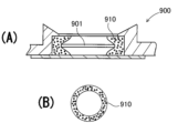
- the ultrasonic atomization device 900 of Patent Document 1 has an ultrasonic vibrator 901 fixed to the atomization chamber via a gasket 910, as shown in the enlarged cross-sectional view of the main part in FIG.
- Gasket 910 has a ring shape, and an ultrasonic transducer 901 is arranged inside thereof.
- the gasket 910 is in close contact with the outer periphery of the ultrasonic vibrator 901 with elastic restoring force, and the ultrasonic vibrator is arranged in the atomization chamber in a watertight structure.
- the gasket 910 is ring-shaped and thicker than the ultrasonic transducer 901, and the ultrasonic transducer 901 is arranged horizontally in the center of the gasket 910 in the vertical direction.
- the center portion of the gasket 910 is pressed by the outer peripheral edge of the ultrasonic transducer 901 and is crushed thinly, thereby being elastically deformed.
- the gasket 910 presses the outer periphery of the ultrasonic transducer 901 in close contact with the elastic restoring force of the elastically deformed region, and arranges the ultrasonic transducer 901 in a horizontal position without being displaced.
- the ultrasonic transducer 901 fixed in the structure shown in the cross-sectional view of FIG. 7 is arranged with the ultrasonic transducer 901 elastically sandwiched between the gasket 910 in the vertical direction, a recess is formed inside the gasket 910.
- An ultrasonic transducer 901 is placed at the bottom of the recess of the lever.
- the ultrasonic transducer 901 As the ultrasonic transducer 901 is used, foreign matter adheres to the surface and the atomization efficiency decreases, but even when the foreign matter is wiped away, liquid remaining in the recesses reduces workability. . This is because if the surface of the ultrasonic transducer 901 is wiped while liquid remains in the recessed portion, foreign matter will be dispersed in the liquid and it will take time and effort to drain the dirty liquid.
- the present invention was developed with the aim of eliminating the above-mentioned drawbacks, and an object of the present invention is to provide an ultrasonic atomization device that can simply, easily, and quickly discharge liquid remaining in the atomization chamber. It's about doing.
- the ultrasonic atomization device of the present invention includes an atomization chamber that generates mist from a liquid using ultrasonic vibrations, an ultrasonic vibrator that ultrasonically vibrates the liquid in the atomization chamber, and a vibrating surface of the ultrasonic vibrator that atomizes.
- the fixing part is disposed in the liquid of the conversion chamber, and the part of the fixing part exposed in the liquid is arranged on the same plane without protruding from the vibration surface of the ultrasonic transducer.
- the submerged exposed part of the fixing part is arranged on the "same plane" without protruding from the vibration surface of the ultrasonic transducer, but in this specification, the "same plane” means only the completely same plane. It is used in a broad sense, including almost the same plane.
- the above-mentioned ultrasonic atomization device has the feature that the liquid remaining in the atomization chamber can be easily and quickly discharged.
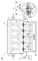
- FIG. 1 is a schematic configuration diagram of an ultrasonic atomization device according to an embodiment of the present invention.
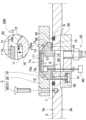
- FIG. 2 is an enlarged sectional view of a main part of the ultrasonic atomization device shown in FIG. 1, showing the state after a gasket holder is attached.
- FIG. 2 is an enlarged sectional view of a main part of the ultrasonic atomization device shown in FIG. 1, showing the state before a gasket holder is attached.
- FIG. 3 is an enlarged sectional view of a main part of an ultrasonic atomization device according to another embodiment of the present invention.
- FIG. 3 is an enlarged sectional view of a main part of an ultrasonic atomization device according to another embodiment of the present invention.
- FIG. 3 is a schematic configuration diagram of an ultrasonic atomization device according to another embodiment of the present invention.
- FIG. 2 is an enlarged sectional view of main parts of a conventional ultrasonic atomization device.
- the ultrasonic atomization device can have the following configuration.
- the ultrasonic atomization device of this embodiment includes an atomization chamber that generates mist from a liquid by ultrasonic vibration, an ultrasonic vibrator that ultrasonically vibrates the liquid in the atomization chamber, and a vibration surface of the ultrasonic vibrator.
- the fixed part is arranged in the liquid of the atomization chamber, and the part of the fixed part exposed in the liquid is arranged on the same plane as the vibration surface of the ultrasonic vibrator without protruding from the vibration surface.
- the above ultrasonic atomization device can simply and easily drain the liquid remaining in the atomization chamber, and moreover, quickly.
- the vibration surface of the ultrasonic vibrator and the submerged part of the fixed part of the ultrasonic vibrator are arranged on the same plane, so that the liquid in the atomization chamber can be discharged. This is because no recesses are formed on the surface of the ultrasonic vibrator, and the liquid can be quickly discharged from the vibrating surface of the ultrasonic vibrator. Therefore, the above-described ultrasonic atomizer has the advantage that when replacing the liquid to be atomized with a different liquid or a new liquid, the old liquid can be easily discharged and replaced with the next liquid. Another feature is that liquid adhering to the vibrating surface of the ultrasonic transducer can be easily removed by wiping.
- ultrasonic atomization devices In ultrasonic atomization devices, foreign matter adhering to the vibration surface of the ultrasonic vibrator causes a decrease in atomization efficiency. Foreign matter adhering to the vibrating surface of the ultrasonic transducer can be removed by wiping. Ultrasonic vibrators can maintain high atomization efficiency by removing foreign matter from the vibrating surface, so ultrasonic atomizers that suppress the decline in atomization efficiency must periodically wipe the vibrating surface of the ultrasonic vibrator. However, in this ultrasonic atomizer, the vibration surface of the ultrasonic vibrator and the submerged part of the fixed part are arranged on the same plane, so that the vibration surface of the ultrasonic vibrator is It has the advantage of being able to easily and quickly remove foreign substances and maintain high atomization efficiency.
- arranging the vibration surface of the ultrasonic transducer and the submerged part of the fixing part on the "same plane” means that the vibration surface of the ultrasonic transducer and the surface of the submerged part of the fixing part are substantially aligned.
- the term is used to include substantially the same plane, for example, 3 mm or less, preferably 2 mm or less, more preferably 1 mm or less.
- the ultrasonic atomization device in addition to the configuration of the first embodiment, can have the following configuration.
- the atomization chamber includes a fixing plate on which the ultrasonic vibrator is fixed via a fixing part, and the fixing part is in close contact with the outer periphery of the ultrasonic transducer.
- a gasket made of a rubber-like elastic material, a gasket holder that holds the gasket in a fixed position, and a connector that connects the gasket holder to a fixed plate, and an ultrasonic vibrator that connects the exposed part of the gasket to the liquid. It is placed on the same plane as the vibration surface.
- the above ultrasonic atomization device arranges the ultrasonic vibrator in the liquid in the atomization chamber through the gasket in a watertight structure, while keeping the vibration surface of the ultrasonic vibrator and the exposed part of the gasket in the liquid on the same plane. Since the gasket is placed at , the atomization efficiency of the ultrasonic transducer can be maintained at a high level at all times. Further, even when the liquid in the atomization chamber is drained out by opening the discharge port provided in the atomization chamber, for example, it can be quickly and completely removed from the vibration surface of the ultrasonic vibrator.
- the ultrasonic atomization device can have the following configuration.
- the vibration surface of the ultrasonic vibrator and the submerged part of the gasket are on the same plane, and the submerged part of the gasket holder is also ultrasonic with the submerged part of the gasket. It is placed on the same plane as the vibrating surface of the vibrator.
- the above-mentioned ultrasonic atomization device has a fixing part consisting of a gasket that arranges the ultrasonic vibrator in the liquid in a watertight structure, and a gasket holder that places the gasket in a fixed position. Since the exposed part in the liquid is placed on the same plane as the vibration surface of the ultrasonic vibrator, the liquid remaining on the vibration surface of the ultrasonic vibrator can be removed while the gasket is brought into close contact with the outer periphery of the ultrasonic vibration using a gasket holder. It has the advantage of being easy and quick to discharge.
- the ultrasonic atomization device can have the following configuration.
- the gasket is provided with a stepped recess that guides the ultrasonic vibrator inward, and the outer circumferential surface of the gasket is formed into a tapered compressed surface whose outer diameter becomes smaller toward the exposed part in the liquid. It is said that Furthermore, the gasket is provided with a retaining ring that is in close contact with the outer peripheral edge of the ultrasonic vibrator between the step recess and the compression surface.
- the gasket holder has a tapered surface that places the compression surface of the gasket on the inside, and by fixing the gasket holder to the fixing plate with a connecting tool, the tapered surface of the gasket holder presses against the compression surface of the gasket.
- the retaining ring is pressed against the outer circumferential edge of the ultrasonic transducer, so that the outer circumferential edge of the ultrasonic vibrator is brought into close contact with the inner circumferential surface of the retaining ring in a watertight structure.
- the above ultrasonic atomization device can press the compressed surface of the gasket with the tapered surface of the gasket holder to bring the retaining ring into close contact with the outer periphery of the ultrasonic vibrator placed in the stepped recess of the gasket.
- the retaining ring is forcibly pressed against the outer periphery of the ultrasonic transducer, so the ultrasonic transducer and gasket can be reliably and stably connected in a watertight structure, and the ultrasonic transducer can be removed from the gasket. It can be arranged so that it does not occur.
- the above-mentioned ultrasonic atomizer has a watertight structure by fixing the gasket holder to the bottom of the ultrasonic vibrator, compressing the gasket and pressing it against the outer periphery of the ultrasonic vibrator.
- the inner shape of the stepped recess of the gasket is set to a size that allows the ultrasonic transducer to be inserted smoothly, so that the ultrasonic transducer can be smoothly inserted into the stepped recess.
- the gasket in which the ultrasonic vibrator is inserted into the stepped recess can be compressed by a gasket holder fixed to the bottom to fix the gasket in a watertight structure. Therefore, the ultrasonic transducer can be smoothly and efficiently set in the stepped recess of the gasket while being attached to a watertight structure via the gasket.
- the ultrasonic atomization device can have the following configuration.
- the shape of the inner circumferential surface of the stepped recess of the gasket that is, the inner circumferential surface of the retaining ring, is adjusted to an inner shape toward the submerged exposed portion when the ultrasonic vibrator is not inserted. It has a tapered shape or an undercut shape to make it smaller.
- a tapered or undercut-shaped retaining ring whose inner shape is reduced toward the exposed part in the liquid is brought into close contact with the outer periphery of the ultrasonic vibrator disposed in the stepped recess.
- the gasket reliably comes into close contact with the outer periphery of the ultrasonic vibrator in the vicinity of the exposed portion in the liquid, thereby achieving an ideal watertight structure between the ultrasonic vibrator and the gasket.
- the ultrasonic atomization device can have the following configuration.
- the inclination angles ( ⁇ 1, ⁇ 2) of the compression surface and the tapered surface with respect to the vertical plane are equal, or the inclination angle ( ⁇ 2) of the tapered surface is greater than the inclination angle ( ⁇ 1) of the compression surface. You can make it bigger.
- the above ultrasonic atomizer uses ultrasonic vibrations by setting the compression surface and the tapered surface at the same angle of inclination ( ⁇ 1, ⁇ 2), and pressing the gasket retaining ring over a wide area with the tapered surface in surface contact with the compression surface.
- the gasket can be evenly attached to the outer edge of the child.
- the inclination angle ( ⁇ 2) of the tapered surface is made larger than the inclination angle ( ⁇ 1) of the compression surface, and the holding ring, which is in close contact with the outer periphery of the ultrasonic transducer, is strongly pressed by the opening edge of the stepped recess so that it does not come off. It can be held like this.
- the ultrasonic atomization device according to the seventh embodiment of the present invention can have the following configuration.
- the inclination angle ( ⁇ 1, ⁇ 2) between the compression surface and the tapered surface can be set to 10 degrees or more and 70 degrees or less.
- the ultrasonic atomizer with the above structure can efficiently press the outer periphery of the ultrasonic vibrator with the gasket's retaining ring through the tapered surface and compressed surface, and also holds the ultrasonic vibrator so that it does not fall out. can.
- the ultrasonic atomization device can have the following configuration.
- an O-ring is sandwiched between the gasket holder and the inner surface of the fixed plate, the gasket holder is pressed against the fixed plate with a connecting tool, and the O-ring is connected between the gasket holder and the fixed plate. It can be sandwiched between
- the above-described ultrasonic atomization device has the feature that the gasket holder and the bottom of the atomization chamber can be reliably connected in a watertight structure by sandwiching the O-ring.
- the ultrasonic atomization device according to the ninth embodiment of the present invention can have the following configuration.
- a spacer is arranged between the gasket and the inner surface of the fixed plate.
- the above ultrasonic atomization device can adjust the thickness of the spacer to make the surfaces of the gasket and the ultrasonic vibrator on the same plane, and the gasket can also be elastically deformed to press the outer periphery of the ultrasonic vibrator.
- the feature is that the pressure can be adjusted. This is done by making the spacer thicker so that the gasket is positioned higher, by making the spacer thinner and lowering the gasket so that the gasket and the ultrasonic transducer are placed on the same plane, and by adjusting the vertical position of the gasket. This is because the pressure with which the tapered surface presses the compression surface can be adjusted.
- the spacer When the spacer is made thicker and the gasket is placed in the raised position, the outer shape pressed against the tapered surface becomes larger, and the compressed surface is strongly pressed and tightly adheres to the outer periphery of the ultrasonic transducer, and the spacer is made thinner and the gasket is lowered. When placed in this position, the outer shape pressed against the tapered surface becomes smaller and the pressing force of the compressed surface is reduced, so that the pressing force of the outer periphery of the ultrasonic transducer can be adjusted to be small.
- the ultrasonic atomization device according to the tenth embodiment of the present invention can have the following configuration.
- a spacer is arranged on the outer periphery of the gasket.
- the ultrasonic atomization device in addition to the configuration of the second embodiment, can have the following configuration.
- the gasket is made of elastomer.
- the ultrasonic atomization device can have the following configuration in addition to the configuration of any one of the first to eleventh embodiments.
- the ultrasonic vibrator has its vibration surface disposed on the lower surface and its upper surface disposed in the air.
- the ultrasonic atomization device of the present invention does not specify the use of the mist obtained by atomizing liquid with an ultrasonic atomizer.
- the ultrasonic atomization device of the present invention can be used, for example, to collect a mist obtained by atomizing a liquid and concentrate the liquid, or to separate a liquid into mist into liquids with different boiling points, or to convert a liquid into a mist to increase the surface area. It is used in equipment that deodorizes odor gases, or equipment that mixes and reacts gas containing liquid mist with other gases using a static mixer, etc., but is not intended to be used specifically for any of the above purposes. .
- Ultrasonic atomizers use ultrasonic vibrations to turn liquid into a fine mist, so they can be used in a variety of applications to efficiently concentrate and separate liquids, deodorize odor gases, or quickly increase the contact area.
- the reactor mixes the mist mixed air and the reactive gas to cause the dissolved components of the mist to react with the reactive gas.
- the present invention does not specify the use of the ultrasonic atomization device, and can be used for all other uses of atomizing liquid.
- the ultrasonic atomizer of the present invention is suitable for use in generating a large amount of mist per unit time, and is therefore most suitable for large-scale testing machines and industrial atomizers.
- the ultrasonic atomization device 100 according to the embodiment of the present invention shown in FIG.
- the mist is separated into the air from the surface of the liquid column P and atomized.
- the ultrasonic transducer 1 is fixed to a fixing plate 5 via a fixing part 2.
- the fixed plate 5 has one surface (upper surface in the figure) as an inner surface 5a that is placed in the liquid, and the other surface (lower surface in the figure) as an outer surface 5b.
- the ultrasonic atomization device 100 includes an atomization chamber 4 having a closed structure to which a liquid W to be atomized is supplied, and a plurality of ultrasonic vibrators 1 that generate mist by ultrasonically vibrating the liquid W in the atomization chamber 4.
- a fixing part 2 in which the vibration surface 1a of the ultrasonic vibrator 1 is placed in the liquid of the atomization chamber 4, and an ultrasonic power source 60 for supplying ultrasonic power to the ultrasonic vibrator 1.
- the fixed part 2 does not protrude from the vibration surface 1a of the ultrasonic transducer 1, and the submerged exposed portion 2a is arranged on the same plane as the vibration surface 1a of the ultrasonic transducer 1.
- an ultrasonic vibrator 1 is fixed to an ultrasonic radiation opening 6 provided in a fixing plate 5 via a fixing part 2.
- the ultrasonic atomizer 100 of FIG. 1 is fixed with the radiation opening 6 of the fixed plate 5 in close contact with a watertight structure, and emits ultrasonic vibrations upward.
- the ultrasonic vibrations emitted upward by the ultrasonic transducer 1 cause the liquid column P to protrude from the liquid surface, and disperse mist from the surface of the liquid column P.
- the fixing part 2 is fixed to the fixing plate 5 of the atomization chamber 4, and arranges the ultrasonic transducer 1 in a horizontal position without shifting.
- the atomization chamber 4 has a closed structure, and as shown in FIG. 1, the supplied liquid W is atomized by ultrasonic vibration, the atomized mist is mixed with a carrier gas, and the mixture is supplied to the outside as mist mixed air.
- the carrier gas is, for example, an inert gas such as nitrogen gas that is substantially free of oxygen.
- This ultrasonic atomization device 100 can ensure safety even when a flammable liquid is atomized in the atomization chamber 4.
- a substantially oxygen-free carrier gas can be used to prevent the atomized liquid from igniting.
- an oxygen sensor is provided to detect the concentration of oxygen contained in the carrier gas in the atomization chamber 4, the carrier gas discharged from the atomization chamber 4, or the carrier gas circulated to the atomization chamber 4.
- the liquid W in the atomization chamber 4 is ultrasonically vibrated, separated from the liquid W in a mist state, and dispersed in the carrier gas.
- a plurality of ultrasonic transducers 1 are fixed to a fixed plate 5 of an atomization chamber 4 filled with a liquid W.
- the ultrasonic vibrator 1 emits ultrasonic waves upward toward the liquid surface to ultrasonically vibrate the liquid surface.
- the ultrasonically vibrated liquid W protrudes from the liquid surface to form a liquid column P, separates from the surface of the liquid column P, and scatters into the carrier gas to become a mist mixed gas.
- the carrier gas is forced into the liquid column P and quickly disperses the mist from the liquid column P.
- the mist is dispersed in the carrier gas to form a mist gas mixture.
- the mist mixture gas is discharged from the atomization chamber 4 to the outside.
- the fixing part 2 of the ultrasonic transducer 1 includes a gasket 10 made of a rubber-like elastic body that is in close contact with the outer periphery of the ultrasonic transducer 1, a gasket holder 20 in which the gasket 10 is placed in a fixed position, and a gasket holder. 20 to the fixing plate 5.
- the gasket 10 is ring-shaped, and in FIGS. 2 and 3, the upper surface of the gasket 10 is provided with a step recess 11 that opens upward and guides the ultrasonic transducer 1 inward. Further, the outer peripheral surface of the gasket 10 is provided with a tapered compression surface 12 whose outer shape becomes smaller toward the submerged exposed portion 10a. Further, a retaining ring 13 is provided between the step recess 11 and the compression surface 12, and the retaining ring 13 is in close contact with the outer peripheral edge 1c of the ultrasonic transducer 1.
- the gasket 10 described above is made of, for example, a ring-shaped elastomer such as synthetic rubber.
- the elastomer of the gasket 10 is not limited to synthetic rubber, but can be made of any other rubber-like elastomer such as natural rubber or elastically deformable plastic.
- the elastic gasket 10 can be tightly pressed against the outer peripheral edge 1c of the ultrasonic transducer 1 by the retaining ring 13, and transmits the pressing force from the gasket holder 20 to generate ultrasonic vibrations toward the center of the ring and/or downward. It is possible to press and compress the child 1.
- the stepped recess 11 of the gasket 10 should have a depth equal to the thickness of the ultrasonic transducer 1 and an inner shape equal to the outer diameter of the ultrasonic transducer 1 so that the ultrasonic transducer 1 can be guided smoothly. It is equal to or slightly smaller than the external shape.
- the gasket 10 has a step recess 11 whose inner shape is equal to the outer shape of the ultrasonic transducer 1. The gasket 10 smoothly guides the ultrasonic transducer 1 into the step recess 11, and allows the gasket holder 20 to move the gasket 10 toward the center. It can be pressed and brought into close contact with the outer peripheral edge 1c of the ultrasonic transducer 1.
- the gasket 10 of the stepped recess 11 whose internal shape is slightly smaller than the external shape of the ultrasonic vibrator 1 guides the ultrasonic vibrator 1 into the stepped recess 11 and generates ultrasonic vibrations by the elastic restoring force of the gasket 10. It can be closely attached to the outer peripheral edge 1c of the child 1. This gasket 10 can also be pressed in the center direction by the gasket holder 20 to ensure tight contact with the outer peripheral edge 1c of the ultrasonic transducer 1. The gasket 10 guides the ultrasonic transducer 1 into the stepped recess 11 so that the vibration surface 1a of the ultrasonic transducer 1 and the submerged exposed portion 10a of the gasket 10 are placed completely on the same plane.
- the surfaces of the ultrasonic transducer 1 and the gasket 10 do not necessarily need to be completely on the same plane, but can be arranged on almost the same plane to achieve the effects of the present invention. . Therefore, the vertical positional deviation between the ultrasonic transducer 1 and the gasket 10 is set to, for example, 2 mm or less, preferably 1.5 mm or less, and more preferably 1 mm or less, so that the surfaces of the ultrasonic transducer 1 and the gasket 10 are on substantially the same plane. can be placed in Therefore, as used herein, "coplanar” refers to. This term is used to include "substantially the same plane.”
- the outer circumferential surface of the gasket 10 is a tapered compressed surface 12 whose outer shape becomes smaller toward the submerged exposed portion 10a.
- the compression surface 12 is preferably tapered along the surface of a cone.
- the ultrasonic transducer 1 is not specified to have a disk shape, so for example, a gasket for arranging a polygonal ultrasonic transducer in a stepped recess may have a compression surface shaped along the surface of a polygonal pyramid. do.
- the gasket 10 is provided with a retaining ring 13 between the compression surface 12 and the stepped recess 11.
- the retaining ring 13 is provided along the outer peripheral edge 1c of the ultrasonic transducer 1, if the ultrasonic transducer 1 is disk-shaped, the retaining ring 13 is formed into a circular ring shape.
- the tapered compression surface 12 of the retaining ring 13 in FIG. 3 is pushed toward the center as indicated by arrow A, its inner circumference is pressed against the outer circumferential edge 1c of the ultrasonic transducer 1 and comes into close contact with it.
- the retaining ring 13 has a width (L) of, for example, 5 mm or less, preferably 3 mm or less, and more preferably 2 mm or less, and is pressed by the compression surface 12 to be elastically deformed and tightly adheres to the outer peripheral edge 1c of the ultrasonic transducer 1. do.
- the width (L) of the retaining ring 13 is too narrow, the amount of elastic deformation caused by being pressed by the compression surface 12 will be small, so it is preferably 1 mm or more, and optimally about 1 mm to 2 mm.
- the gasket 10 shown in FIG. 2 has a spacer 40 disposed between it and the fixed plate 5.
- the gasket 10 has a ring recess 14 on the bottom surface for arranging the spacer 40 in a fixed position, and a guide cylinder part 15 is provided on the inner circumference of the bottom surface to guide the spacer 40 on the outside of the guide cylinder part 15.
- a ring-shaped stepped plane 16 is provided.
- the guide tube portion 15 is inserted with its outer shape equal to the inner shape of the radiation opening 6 of the fixed plate 5.
- the spacer 40 is inserted into the guide cylinder portion 15 of the gasket 10 and placed in a fixed position.
- the vertical position with respect to the fixed plate 5 can be adjusted by changing the thickness of the spacer 40.
- the vertical position of the gasket 10 can be adjusted by adjusting the thickness of the spacer 40, so by adjusting the thickness of the spacer 40, the submerged exposed portion 10a of the gasket 10 and the submerged exposed portion 20a of the gasket holder 20 are on the same plane. Can be placed.
- the spacer 40 thicker, the relative position of the gasket 10 to the fixed plate 5, that is, to the gasket holder 20, can be increased, and by making the spacer 40 thinner, the relative position of the gasket 10 to the gasket holder 20 can be lowered.
- the submerged exposed portions 20a of 20 are arranged completely on the same plane or substantially on the same plane.
- the gasket holder 20 is fixed to the surface of the fixed plate 5, and presses the retaining ring 13 of the gasket 10 against the outer peripheral edge 1c of the ultrasonic transducer 1.
- the gasket holder 20 can be manufactured by cutting a metal plate having a thickness of 5 mm or more into a ring shape, for example.
- the gasket holder 20 shown in FIGS. 2 and 3 includes a tapered surface 21 on the inner peripheral surface of which the gasket 10 is arranged.
- the gasket holder 20 is fixed to the fixing plate 5 with the inner surface of the tapered surface 21 in surface contact with the compression surface 12 of the gasket 10, and is compressed by pressing the compression surface 12 of the gasket 10 with surface pressure.
- the tapered surface 21 compresses the compression surface 12 of the gasket 10, elastically deforming the gasket 10, and attaching the retaining ring 13 to the outer peripheral edge 1c of the ultrasonic transducer 1. Press it to make it adhere to the watertight structure. Therefore, when the gasket holder 20 is not fixed to the fixing plate 5, the inner shape of the tapered surface 21 is smaller than the compression surface 12 of the gasket 10.
- the tapered surface 21 smaller than the compression surface 12 presses the compression surface 12 to compress the gasket 10, and the retaining ring 13 is attached to the outer peripheral edge 1c of the ultrasonic transducer 1. Bring it into close contact.
- the tapered surface 21 compresses the compression surface 12 of the gasket 10, and the retaining ring 13 of the gasket 10
- the outer peripheral edge 1c of the ultrasonic transducer 1 can be pressed against the watertight structure.
- the gasket 10 that guides the disc-shaped ultrasonic transducer 1 into the stepped recess 11 has a tapered surface 21 and a compression surface 12 shaped along a conical surface, as shown in the enlarged cross-sectional view of FIG. has an inner diameter smaller than that of the compression surface 12.
- the retaining ring 13 can be brought into close contact with the outer peripheral edge 1c of the ultrasonic transducer 1.
- the tapered surface 21 and the compression surface 12 preferably have the same inclination angle, and the tapered surface 21 presses and compresses the compression surface 12 with the tapered surface 21 and the compression surface 12 in surface contact.
- the gasket 10 can be compressed by making the inner diameter of the upper end smaller than the compression surface 12.
- the outer peripheral surface of the ring-shaped gasket 10 has a tapered compression surface 12 whose outer shape becomes smaller toward the submerged exposed portion 10a, and the gasket holder 20 is formed by guiding the compression surface 12 of the gasket 10 inward. It has a tapered surface 21.
- the compression surface 12 and the tapered surface 21 have slopes that are inclined with respect to the vertical plane, forming respective slope angles ( ⁇ 1, ⁇ 2). If the inclination angles ( ⁇ 1, ⁇ 2) of the compression surface 12 and the tapered surface 21 are too small, the retaining ring 13 may be moved toward the outer peripheral edge 1c of the ultrasonic transducer 1 while the gasket holder 20 is fixed to the fixing plate 5.
- the inclination angles ( ⁇ 1, ⁇ 2) between the compression surface 12 and the tapered surface 21 are preferably at least 10 degrees and at most 70 degrees, more preferably at least about 40 degrees and at most 60 degrees, and the retaining ring 13 is The outer peripheral edge 1c of the vibrator 1 is brought into close contact with a watertight structure.
- the inclination angle ( ⁇ ) is set to an optimal value in consideration of the frictional resistance between the tapered surface 21 and the compression surface 12, the elasticity of the gasket 10, and the like.
- the inclination angle ( ⁇ 1) of the compression surface 12 of the gasket 10 and the inclination angle ( ⁇ 2) of the tapered surface 21 of the gasket holder 20 can be the same inclination angle, and the inclination angle ( ⁇ 2) of the tapered surface 21 can be the same as the inclination angle ( ⁇ 2) of the compression surface 21. It is also possible to make the angle of inclination ( ⁇ 1) larger than 12.
- the tapered surface 21 can be brought into contact with the compression surface 12 over a wide area in a surface contact state, and the gasket The gasket 10 can be evenly and closely attached to the outer peripheral edge 1c of the ultrasonic transducer 1 by pressing the retaining ring 13 of the 10.
- the retaining ring 13 that is in close contact with the outer peripheral edge 1c of the ultrasonic transducer 1 is attached to the opening edge of the stepped recess 11. It has the advantage of being able to hold the ultrasonic transducer 1 so that it does not fall out by pressing strongly.
- Gasket holder 20 is fixed to fixing plate 5 via connector 30.
- the connector 30 in FIG. 2 is a set screw 31, which passes through the gasket holder 20 and is screwed into the female screw hole 7 provided in the fixing plate 5 to fix the gasket holder 20 to the fixing plate 5.
- the connector 30 of the set screw 31 passes through the gasket holder 20 and is screwed into the bottom of the atomization chamber 4, so that the gasket holder 20 can be easily and securely fixed to the bottom of the atomization chamber 4.
- the present invention is not limited to the set screw 31 that screws the connector 30 into the fixing plate 5 through the gasket holder 20, but any other structure that can fix the gasket holder 20 to the fixing plate 5, for example, as shown in the figure.
- the gasket holder is fixed to the fixing plate by inserting a threaded rod fixed vertically to the fixing plate into the through hole of the gasket holder and screwing a nut onto the threaded part that protrudes upward from the gasket holder.
- the gasket holder can be fixed to the fixing plate by welding or gluing.
- an O-ring 42 is sandwiched between the gasket holder 20 and the fixed plate 5 to connect the gasket holder 20 and the fixed plate 5 in a waterproof structure.
- the fixed plate 5 is provided with a guide groove 8 for the O-ring 42. After arranging the O-ring 42 in the guide groove 8 before attaching and fixing the gasket holder 20 shown in FIG.
- the lower surface of the gasket holder 20 and the inner surface 5a of the fixed plate 5 are sandwiched to connect the two in a waterproof structure.
- the ultrasonic atomization device 100 in FIG. 2 includes an airtight chamber 18 below the ultrasonic vibrator 1.
- the lower surface of the ultrasonic transducer 1 is exposed in the airtight chamber 18.
- a closing plate 50 that closes the lower surface of the radiation opening 6 is fixed to the outer surface 5b.
- the closing plate 50 is fixed to the outer surface 5b of the fixed plate 5 via a connecting screw 51.
- the fixed plate 5 closes the lower opening of the radiation opening 6 with a closing plate 50 and the upper opening of the radiation opening 6 with a gasket 10 and the ultrasonic vibrator 1 to form an airtight chamber 18.
- a lead wire 62 connected to the ultrasonic transducer 1 is disposed and drawn out from the closure plate 50.
- the illustrated closing plate 50 connects the pipe joints 52.
- the pipe joint 52 can be used as a pipe joint for leading the lead wire 62 to the outside or for supplying substantially oxygen-free gas to the airtight chamber 18.
- a more reliable explosion-proof structure can be realized by supplying a gas that does not substantially contain oxygen to the airtight chamber 18 and maintaining the internal pressure higher than atmospheric pressure.
- the substantially oxygen-free gas can be an inert gas such as nitrogen.
- the internal pressure of the airtight chamber 18 is maintained high, and liquid leakage from the atomization chamber 4 can be suppressed.Furthermore, by using a flammable liquid as the liquid W to be atomized, this liquid can temporarily This is because even if the gas leaks through the outer peripheral edge 1c of the gas, the lower airtight chamber 18 filled with substantially oxygen-free gas can be prevented from catching fire.
- the internal pressure of the atomization chamber 4 is atmospheric pressure (external pressure) except for special applications, so by keeping the internal pressure of the airtight chamber 18 higher than atmospheric pressure, the internal pressure of the airtight chamber 18 can be maintained for special applications.
- the internal pressure of the atomization chamber 4 can be maintained higher than the internal pressure of the atomization chamber 4 except for.
- an oxygen sensor (not shown) is provided in the airtight chamber 18 to detect the oxygen concentration in the airtight chamber 18, and when the oxygen concentration exceeds a threshold value, the gas in the airtight chamber 18 is exhausted and the operation is stopped. Furthermore, by forcibly blowing a gas such as nitrogen gas that does not substantially contain oxygen into the airtight chamber 18, high safety can be ensured in the ultrasonic atomization device that atomizes flammable liquids. .
- the surfaces of the ultrasonic vibrator 1, gasket 10, and gasket holder 20 are arranged on the same plane or substantially on the same plane.
- This ultrasonic atomization device 100 exposes the entire surface of the ultrasonic vibrator 1 and disposes the gasket 10 and the gasket holder 20 on the same plane or almost the same plane, so that the liquid is discharged from the atomization chamber 4.
- This has the advantage that by opening the exhaust port and discharging the liquid from the atomization chamber 4, the liquid remaining on the surface of the ultrasonic transducer 1 can be discharged most quickly.
- the ultrasonic atomization device 200 has the inner shape of the step recess 11 of the gasket 10 submerged in the non-inserted state in which the ultrasonic vibrator 1 is not inserted.
- the inner shape toward the exposed portion 10a it is possible to more reliably prevent the ultrasonic transducer 1 from slipping out of the stepped recess 11. This is because, as shown by arrow C in FIG. 4, the retaining ring 13 of the gasket 10 strongly presses the upper part of the outer peripheral edge 1c of the ultrasonic transducer 1, thereby preventing the ultrasonic transducer 1 from coming off. .
- the inner shape of the step recess 11 is tapered so that the inner shape becomes smaller toward the submerged exposed part 10a, but the inner shape of the step recess 11 is an undercut shape so that the ultrasonic vibrator 1 can also be prevented from slipping out of the stepped recess 11.
- the ultrasonic atomization device 300 has a gasket 10 that is arranged along the opening edge of the stepped recess 11, along the outer peripheral edge of the surface of the ultrasonic vibrator 1, as shown in the enlarged cross-sectional view of FIG.
- a surface rib 17 covering the ultrasonic transducer 1c is integrally provided, and the surface rib 17 presses the outer peripheral edge 1c of the surface of the ultrasonic transducer 1, thereby preventing the ultrasonic transducer 1 from coming off.
- the ultrasonic atomization device 400 includes an atomization case 3 having an atomization chamber 4 inside which atomizes the liquid W by ultrasonic vibration.
- a plurality of ultrasonic vibrators 1 are disposed facing downwardly with respect to the liquid W stored in the atomization case 3, and ultrasonic vibrations are radiated downwardly to the flowing liquid column Q.
- a peripheral wall 53 is provided on a fixed plate 5 that fixes the ultrasonic vibrator 1, and the fixed plate 5 is placed in the liquid.
- the peripheral wall 53 is higher than the liquid level and prevents the liquid W from entering the upper surface side of the fixed plate 5.
- the atomization case 3 is divided into upper and lower sections by a partition plate 55, with a liquid chamber 57 above the partition plate 55 and an air chamber 58 below.
- the partition plate 55 is provided with a drain opening 56 through which the liquid W in the liquid chamber 57 naturally falls.
- the liquid drain opening 56 has an inner diameter, for example, a diameter of 3 mm to 10 mm, through which the liquid W naturally flowing down from the liquid chamber 57 flows down in the air chamber 58 in the form of a liquid column Q.
- Ultrasonic vibrations are emitted from the ultrasonic vibrator 1, and the mist is separated from the surface of the liquid column Q flowing down from the liquid drain opening 56 into the air chamber 58.
- the ultrasonic atomization device 400 of FIG. 6 uses the air chamber 58 of the atomization case 3 as the atomization chamber 4 with a closed structure, and mixes a carrier gas with the mist atomized by ultrasonic vibration to externally produce mist mixed air. is being discharged.
- the ultrasonic vibrator 1 can be fixed to the fixing plate 5 via the fixing part 2 of the embodiment described above.
- a peripheral wall 53 connected to the fixed plate 5 in a watertight manner has an upper end fixed to the top plate 59 of the atomization case 3, and the fixed plate 5, the peripheral wall 53, and the top plate 59 form an airtight chamber 18.
- the airtight chamber 18 has a lead wire 62 connected to the ultrasonic transducer 1 arranged therein. The lead wire 62 is drawn out from the airtight chamber 18 and connected to the ultrasonic power source 60.
- the airtight chamber 18 can supply substantially oxygen-free gas to ensure safety.
- the present invention is an ultrasonic atomizer that generates mist by ultrasonically vibrating a liquid, and is particularly suitable for an ultrasonic atomizer that can smoothly wipe away foreign matter adhering to the surface of an ultrasonic vibrator. used for.
Landscapes
- Chemical & Material Sciences (AREA)
- Engineering & Computer Science (AREA)
- Dispersion Chemistry (AREA)
- Combustion & Propulsion (AREA)
- Mechanical Engineering (AREA)
- General Engineering & Computer Science (AREA)
- Special Spraying Apparatus (AREA)
Priority Applications (1)
| Application Number | Priority Date | Filing Date | Title |
|---|---|---|---|
| JP2024516257A JPWO2023204191A1 (https=) | 2022-04-18 | 2023-04-17 |
Applications Claiming Priority (2)
| Application Number | Priority Date | Filing Date | Title |
|---|---|---|---|
| JP2022-068541 | 2022-04-18 | ||
| JP2022068541 | 2022-04-18 |
Publications (1)
| Publication Number | Publication Date |
|---|---|
| WO2023204191A1 true WO2023204191A1 (ja) | 2023-10-26 |
Family
ID=88419830
Family Applications (1)
| Application Number | Title | Priority Date | Filing Date |
|---|---|---|---|
| PCT/JP2023/015373 Ceased WO2023204191A1 (ja) | 2022-04-18 | 2023-04-17 | 超音波霧化装置 |
Country Status (2)
| Country | Link |
|---|---|
| JP (1) | JPWO2023204191A1 (https=) |
| WO (1) | WO2023204191A1 (https=) |
Citations (5)
| Publication number | Priority date | Publication date | Assignee | Title |
|---|---|---|---|---|
| JPS51131708U (https=) * | 1975-04-16 | 1976-10-23 | ||
| JP2005270888A (ja) * | 2004-03-25 | 2005-10-06 | Choonpa Jozosho Kk | 溶液の濃縮方法とこの方法に使用される濃縮装置 |
| JP2008036394A (ja) * | 2006-07-14 | 2008-02-21 | Matsushita Electric Ind Co Ltd | 霧化装置および同装置を備えた食器洗い機 |
| JP2008207055A (ja) * | 2007-02-23 | 2008-09-11 | Mitsubishi Electric Corp | 超音波霧化装置及びそれを備えた設備機器 |
| JP2016153117A (ja) * | 2015-02-18 | 2016-08-25 | 株式会社良品計画 | アロマディフューザー |
-
2023
- 2023-04-17 JP JP2024516257A patent/JPWO2023204191A1/ja active Pending
- 2023-04-17 WO PCT/JP2023/015373 patent/WO2023204191A1/ja not_active Ceased
Patent Citations (5)
| Publication number | Priority date | Publication date | Assignee | Title |
|---|---|---|---|---|
| JPS51131708U (https=) * | 1975-04-16 | 1976-10-23 | ||
| JP2005270888A (ja) * | 2004-03-25 | 2005-10-06 | Choonpa Jozosho Kk | 溶液の濃縮方法とこの方法に使用される濃縮装置 |
| JP2008036394A (ja) * | 2006-07-14 | 2008-02-21 | Matsushita Electric Ind Co Ltd | 霧化装置および同装置を備えた食器洗い機 |
| JP2008207055A (ja) * | 2007-02-23 | 2008-09-11 | Mitsubishi Electric Corp | 超音波霧化装置及びそれを備えた設備機器 |
| JP2016153117A (ja) * | 2015-02-18 | 2016-08-25 | 株式会社良品計画 | アロマディフューザー |
Also Published As
| Publication number | Publication date |
|---|---|
| JPWO2023204191A1 (https=) | 2023-10-26 |
Similar Documents
| Publication | Publication Date | Title |
|---|---|---|
| CN1178755C (zh) | 液体喷雾装置 | |
| CN1630562A (zh) | 液体喷头及包含这种液体喷头和容器的装置 | |
| CN109414717A (zh) | 具有可替换部分的气雾产生装置 | |
| JP2006502851A (ja) | 傾斜オリフィス・プレートを有する噴霧装置及び該噴霧装置のための交換用リザーバ | |
| AU2019330440A1 (en) | Environment-friendly sucking device applying vacuum principle | |
| WO2023204191A1 (ja) | 超音波霧化装置 | |
| US20070051827A1 (en) | Spraying device | |
| KR20160062644A (ko) | 휴대용 미스트기기 | |
| US20080041972A1 (en) | Spraying structure for an atomizer | |
| CN216394853U (zh) | 一种雾化装置 | |
| JP5142015B2 (ja) | 容器装置およびキャップ保持体 | |
| US11864589B2 (en) | Atomizer | |
| WO2021057237A1 (zh) | 可储存物料的液体化妆笔 | |
| WO2023204190A1 (ja) | 超音波霧化装置 | |
| JP2011191256A (ja) | クロマトカラム及びその可動栓 | |
| JP2000312849A (ja) | 超音波霧化装置 | |
| CN113856977B (zh) | 超声波喷雾装置 | |
| CN102873020A (zh) | 兆声波换能器的连接盖 | |
| RU2007123341A (ru) | Скруббер с подвижной насадкой | |
| JP6646809B2 (ja) | 液体吐出用の吐出ノズル | |
| CN213285014U (zh) | 一种雾化装置 | |
| JPH044853Y2 (https=) | ||
| US20110233300A1 (en) | Atomization unit with negative pressure actuator | |
| CN202909926U (zh) | 兆声波换能器的连接盖 | |
| CN220678368U (zh) | 便携式雾化机 |
Legal Events
| Date | Code | Title | Description |
|---|---|---|---|
| 121 | Ep: the epo has been informed by wipo that ep was designated in this application |
Ref document number: 23791839 Country of ref document: EP Kind code of ref document: A1 |
|
| WWE | Wipo information: entry into national phase |
Ref document number: 2024516257 Country of ref document: JP |
|
| NENP | Non-entry into the national phase |
Ref country code: DE |
|
| 122 | Ep: pct application non-entry in european phase |
Ref document number: 23791839 Country of ref document: EP Kind code of ref document: A1 |