WO2023203810A1 - 金属線加熱装置、金属線加熱方法及び金属製品製造方法 - Google Patents
金属線加熱装置、金属線加熱方法及び金属製品製造方法 Download PDFInfo
- Publication number
- WO2023203810A1 WO2023203810A1 PCT/JP2022/044970 JP2022044970W WO2023203810A1 WO 2023203810 A1 WO2023203810 A1 WO 2023203810A1 JP 2022044970 W JP2022044970 W JP 2022044970W WO 2023203810 A1 WO2023203810 A1 WO 2023203810A1
- Authority
- WO
- WIPO (PCT)
- Prior art keywords
- metal wire
- heating
- storage tank
- cooling liquid
- heating chamber
- Prior art date
- Legal status (The legal status is an assumption and is not a legal conclusion. Google has not performed a legal analysis and makes no representation as to the accuracy of the status listed.)
- Ceased
Links
Images

Classifications
-
- C—CHEMISTRY; METALLURGY
- C21—METALLURGY OF IRON
- C21D—MODIFYING THE PHYSICAL STRUCTURE OF FERROUS METALS; GENERAL DEVICES FOR HEAT TREATMENT OF FERROUS OR NON-FERROUS METALS OR ALLOYS; MAKING METAL MALLEABLE, e.g. BY DECARBURISATION OR TEMPERING
- C21D1/00—General methods or devices for heat treatment, e.g. annealing, hardening, quenching or tempering
-
- C—CHEMISTRY; METALLURGY
- C21—METALLURGY OF IRON
- C21D—MODIFYING THE PHYSICAL STRUCTURE OF FERROUS METALS; GENERAL DEVICES FOR HEAT TREATMENT OF FERROUS OR NON-FERROUS METALS OR ALLOYS; MAKING METAL MALLEABLE, e.g. BY DECARBURISATION OR TEMPERING
- C21D1/00—General methods or devices for heat treatment, e.g. annealing, hardening, quenching or tempering
- C21D1/26—Methods of annealing
-
- C—CHEMISTRY; METALLURGY
- C21—METALLURGY OF IRON
- C21D—MODIFYING THE PHYSICAL STRUCTURE OF FERROUS METALS; GENERAL DEVICES FOR HEAT TREATMENT OF FERROUS OR NON-FERROUS METALS OR ALLOYS; MAKING METAL MALLEABLE, e.g. BY DECARBURISATION OR TEMPERING
- C21D1/00—General methods or devices for heat treatment, e.g. annealing, hardening, quenching or tempering
- C21D1/74—Methods of treatment in inert gas, controlled atmosphere, vacuum or pulverulent material
-
- C—CHEMISTRY; METALLURGY
- C21—METALLURGY OF IRON
- C21D—MODIFYING THE PHYSICAL STRUCTURE OF FERROUS METALS; GENERAL DEVICES FOR HEAT TREATMENT OF FERROUS OR NON-FERROUS METALS OR ALLOYS; MAKING METAL MALLEABLE, e.g. BY DECARBURISATION OR TEMPERING
- C21D9/00—Heat treatment, e.g. annealing, hardening, quenching or tempering, adapted for particular articles; Furnaces therefor
- C21D9/52—Heat treatment, e.g. annealing, hardening, quenching or tempering, adapted for particular articles; Furnaces therefor for wires; for strips ; for rods of unlimited length
- C21D9/54—Furnaces for treating strips or wire
- C21D9/56—Continuous furnaces for strip or wire
- C21D9/60—Continuous furnaces for strip or wire with induction heating
-
- Y—GENERAL TAGGING OF NEW TECHNOLOGICAL DEVELOPMENTS; GENERAL TAGGING OF CROSS-SECTIONAL TECHNOLOGIES SPANNING OVER SEVERAL SECTIONS OF THE IPC; TECHNICAL SUBJECTS COVERED BY FORMER USPC CROSS-REFERENCE ART COLLECTIONS [XRACs] AND DIGESTS
- Y02—TECHNOLOGIES OR APPLICATIONS FOR MITIGATION OR ADAPTATION AGAINST CLIMATE CHANGE
- Y02P—CLIMATE CHANGE MITIGATION TECHNOLOGIES IN THE PRODUCTION OR PROCESSING OF GOODS
- Y02P10/00—Technologies related to metal processing
- Y02P10/25—Process efficiency
Definitions
- the present disclosure relates to a metal wire heating device, a metal wire heating method, and a metal product manufacturing method.
- metal wire heating devices used in the process of heating metal wires are known.
- a metal wire heating device for example, a dielectric current type continuous annealing device for annealing a metal wire has been proposed (see Japanese Utility Model Publication No. 1-149455).
- a metal wire heating device includes a casing that forms a heating chamber that heats a metal wire to be heated, a transport mechanism that continuously transports the metal wire to the heating chamber, and a lower part of the heating chamber.
- the lower end of the casing is disposed below a set liquid level of the storage tank, and the conveyance mechanism is configured to cool the heated metal wire.
- the metal wire is supplied to the heating chamber via the cooling liquid, and the metal wire is discharged from the heating chamber.
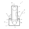
- FIG. 1 is a schematic front sectional view of a metal wire heating device according to an embodiment of the present disclosure in a used state.
- FIG. 2 is a schematic front sectional view of a modification of the metal wire heating device of FIG.
- Patent Document 1 The metal wire heating device of Patent Document 1 described above lacks airtightness in the area where the metal wire is heated, so there is a concern that the metal wire being heated may be oxidized.
- the purpose of the present disclosure was made based on such circumstances, and is to provide a metal wire heating device that can easily suppress oxidation of the metal wire being heated.
- the metal wire heating device of the present disclosure easily suppresses oxidation of the metal wire being heated.
- a metal wire heating device includes a casing that forms a heating chamber having a heating section that heats a metal wire to be heated, and a casing that continuously conveys the metal wire to the heating section of the heating chamber.
- a transport mechanism, and a storage tank provided below the heating chamber and storing a cooling liquid for cooling the heated metal wire, the lower end of the casing being arranged below a set liquid level of the storage tank.
- the conveyance mechanism is provided to supply the metal wire to the heating chamber via the cooling liquid in the storage tank, and to discharge the metal wire from the heating chamber.
- set liquid level means the liquid level of the coolant stored during use that was assumed when the device was designed. For example, if an overflow pipe is provided, the position where the coolant is discharged from the overflow pipe. means.
- the metal wire is supplied to the heating chamber via the cooling liquid, and the metal wire is discharged from the heating chamber via the cooling liquid.
- the metal wire is supplied to the heating chamber via the cooling liquid, and the metal wire is discharged from the heating chamber via the cooling liquid.
- the storage tank is arranged to close the storage tank main body that stores the cooling liquid and an upper part of the storage tank main body, and an inlet port for introducing the metal wire. and a lid having an outlet for discharging the metal wire, and preferably a semi-airtight chamber is provided in the storage tank by the lid.
- the semi-airtight chamber closed by the lid above the liquid level comes into contact with the atmosphere only through the inlet or outlet, making it easy to reduce the oxygen concentration in this semi-airtight chamber. This makes it easier to suppress oxidation of the metal wire.
- the cooling liquid supply mechanism further includes a cooling liquid supply mechanism that supplies the cooling liquid to the storage tank, and a cylindrical body that is arranged in the casing and has an upper end protruding above a set liquid level of the storage tank, and the cooling liquid supply mechanism
- the cooling liquid is supplied from above the cylinder.
- the heating temperature of the metal wire can be easily and reliably adjusted by adjusting the liquid level of the cylinder by the amount of cooling liquid supplied to the cylinder by the cooling liquid supply mechanism.
- a metal wire heating method is a method of heating a metal wire using the metal wire heating device having the above configuration in which a cooling liquid is stored in the storage tank up to a set liquid level. By this method, oxidation of the metal wire during heating can be easily suppressed.
- a metal product manufacturing method includes a step of heating a metal wire by the metal wire heating method having the above configuration, and a step of turning the metal wire after this heating step into a product.
- the metal wire heating device (hereinafter sometimes simply referred to as the heating device) 1 shown in FIG. 1 includes a casing 30 that forms a heating chamber A for heating a metal wire X to be heated, and a metal wire
- the metal wire X is provided with a transport mechanism 70 for transporting the metal wire X, and a water tank 10 that is provided below the heating chamber A and stores a cooling liquid for cooling the heated metal wire X.
- a copper wire is mentioned, for example.
- the conveyance mechanism 70 is provided to supply the metal wire X to the heating chamber A via a supply port 13a, which will be described later, a semi-airtight chamber B (on the right side in FIG. 1), and a cooling liquid in the water tank 10. Further, the transport mechanism 70 is provided to discharge the metal wire X from the heating chamber A via the cooling liquid in the water tank 10, the semi-airtight chamber B (on the left side in FIG. 1), and a discharge port 13b, which will be described later. That is, the metal wire X supplied to and discharged from the heating chamber A passes through the cooling liquid in the water tank 10. In addition, in the upper part of FIG. 1, the metal wire has been done.
- the conveyance mechanism 70 has a pair of upper and lower rollers 71 and 73 over which the metal wire X is spanned.
- the lower roller 71 is arranged below the set liquid level of the water tank 10, and is arranged in the cooling water of the water tank 10 when in use.
- the lower roller 71 receives the metal wire X that has passed through the supply port 13a, and conveys it toward the upper roller 73.
- the upper roller 73 is arranged within the heating chamber A.
- the upper roller 73 is located above the lower roller 71, receives the metal wire X conveyed from the lower roller 71 as described above, rotates it half a turn, and conveys it to the lower roller 71.
- the metal wire X conveyed from the upper roller 73 passes through the discharge port 13b via the lower roller 71 and is discharged.
- the tension of a pair of upper and lower rollers is preferably 10 N or more and 20 N or less per 1 mm 2 of cross-sectional area.
- the water tank 10 includes, for example, a water tank main body 11 for storing cooling liquid, and a lid 13 disposed to close an upper opening of the water tank main body 11.
- the water tank 10 also has an overflow pipe 15 for controlling the liquid level of the water tank main body 11 as shown in FIG. Coolant is discharged to the outside of the water tank 10 via the overflow pipe 15.
- the upper opening position of the overflow pipe 15 corresponds to the set liquid level of the coolant stored during use, which was assumed at the time of device design.
- the water tank body 11 has a form that allows cooling liquid to be stored above the lower end 30a of the casing 30, which will be described later. Further, the water tank body 11 is provided so as to maintain the above-mentioned lower roller 71 in a state immersed in the stored coolant.
- the aquarium main body 11 has a bottom wall and a side wall erected upward from the periphery of the bottom wall so as to have a U-shaped longitudinal section as a whole, and is open at the top.
- the lid 13 is provided to close the upper opening of the water tank body 11.
- a heating chamber A that is airtightly provided by the casing 30 as described above, and a semi-air chamber where only the supply port 13a and the discharge port 13b are opened as described later.
- a supply port 13a through which the metal wire X is supplied is formed in the lid body 13.
- the metal wire X is supplied to the water tank 10 (the lower roller 71 disposed therein) through this supply port 13a.
- a discharge port 13b through which the metal wire X is discharged is formed in the lid body 13.
- the metal wire X is discharged from the water tank 10 (the lower roller 71 disposed therein) through the discharge port 13b.
- the water tank 10 has a semi-airtight chamber (the space between the lid body 13 and the coolant wall surface) that is in contact with the outside air only through the supply port 13a and the discharge port 13b, oxidation of the metal wire X can be further suppressed. can.
- the opening area of the supply port 13a is not particularly limited, it is preferably 5 times or more and 100 times or less the cross-sectional area of the metal wire X.
- This upper limit is more preferably 50 times, and even more preferably 25 times.
- This lower limit is more preferably 10 times, and even more preferably 15 times.
- the opening area is equal to or larger than the lower limit, the metal wire X can easily pass therethrough.
- the opening area of the supply port 13a is less than or equal to the above-mentioned upper limit, it is easy to suppress the outside air flowing into the semi-airtight chamber B.
- the opening area of the discharge port 13b is not particularly limited, it is preferably 5 times or more and 100 times or less the cross-sectional area of the metal wire X.
- This upper limit is more preferably 50 times, and even more preferably 25 times.
- This lower limit is more preferably 10 times, and even more preferably 15 times.
- the opening area is equal to or larger than the lower limit, the metal wire X can easily pass therethrough.
- the opening area of the discharge port 13b is less than or equal to the above-mentioned upper limit, it is easy to suppress the outside air flowing into the semi-airtight chamber B.
- the casing 30 is a member for forming an airtight heating chamber A above the set liquid level of the water tank 10.
- the casing 30 is provided in a cylindrical shape (with a lid) that is closed at the top and opened at the bottom, and the lower end 30a of the casing 30 is positioned below the set liquid level of the coolant stored in the water tank 10. It is provided. Thereby, the heating chamber A is isolated from the outside air by the cooling liquid in the water tank 10 and the casing 30, and the inflow of oxygen into the heating chamber A is suppressed.
- the side wall of the casing 30 and the inner peripheral surface of the lid 13 are hermetically joined, but the side wall of the casing 30 and the inner peripheral surface of the lid 13 may be spaced apart. good.
- the heating chamber A of the heating device 1 includes a heating section 50 that heats the metal wire X.
- the heating unit 50 heats the metal wire X using an induction current method. Note that, as the heating device constituting the heating section 50, it is also possible to employ a device that heats by a method other than the dielectric current method.
- the heating device 1 may further include a coolant supply mechanism 90 that supplies a coolant for cooling the metal wire X to the water tank 10, as shown in FIG. 2, for example.
- the coolant supply mechanism 90 receives the coolant from the overflow pipe 15 of the water tank 10 and returns the coolant from above the water tank 10, thereby supplying the coolant in the water tank 10 in a circulating manner.
- the coolant supply mechanism 90 preferably has an introduction path (not shown) for introducing new coolant.
- the coolant supply mechanism 90 preferably includes an oxygen removal device 93 that removes oxygen contained in the coolant taken out from the water tank 10. Thereby, the oxygen concentration in the heating chamber A and the semi-airtight chamber B can be better controlled.
- the coolant supply mechanism 90 preferably includes a filter 95 that removes impurities contained in the coolant taken out from the water tank 10. Thereby, it is possible to suppress adhesion of impurities to the metal wire X to be processed.
- the coolant supply mechanism 90 preferably includes a pump 97 for circulating the coolant. This pump 97 allows cooling fluid to be supplied from above the cylindrical body 51 as described later.
- the heating device 1 may further include a cylindrical body 51 disposed within the casing 30 and having an upper end protruding above the liquid level of the water tank 10.
- the metal wire X to be conveyed is inserted into the cylinder 51.
- the lower end of this cylindrical body 51 is located below the liquid level of the water tank 10.
- the cylindrical body 51 has a concentric cylindrical shape, it is not limited thereto, and may have a square cylindrical shape or a shape having a tapered portion that widens at the top.
- the cooling liquid is supplied from above the cylindrical body 51 by the cooling liquid supply mechanism 90.
- the cooling liquid supply mechanism 90 By adjusting this supply amount, the liquid level in the cylinder 51 can be adjusted, and therefore the amount of heating of the metal wire X can be adjusted. Furthermore, since the cylinder 51 is located above the water tank 10 , the cooling liquid overflowing from the cylinder 51 is supplied to the water tank 10 .
- the heating device 1 may further include an inert gas supply mechanism 91 that supplies inert gas to the heating chamber A, as shown in FIG. 2, for example.
- an inert gas supply mechanism 91 it is possible to employ, for example, a nitrogen gas supply device.
- the inert gas supply mechanism 91 supplying inert gas to the heating chamber A, the oxygen concentration in the heating chamber A can be suppressed.
- the inert gas supplied to the heating chamber A is taken into the cooling liquid in the water tank 10, and the inert gas in this cooling liquid is supplied to the semi-airtight chamber B. This also contributes to suppressing the oxygen concentration in the semi-airtight chamber B.
- the inert gas supply mechanism 91 it is also possible to provide the inert gas supply mechanism 91 to directly supply the inert gas to the semi-airtight chamber B.
- the metal wire heating device 1 the metal wire X is supplied to the heating chamber A via the cooling liquid and is also discharged from the heating chamber A via the cooling liquid. ) is difficult to flow in, thereby making it easier to suppress oxidation of the metal wire X.
- the oxygen concentration in the semi-airtight chamber B can be easily reduced.
- the casing 30 since the lower end 30a of the casing 30 is disposed below the set liquid level of the water tank 10, and the casing 30 partitions the semi-airtight chamber B and the heating chamber A by (the liquid level of) the cooling liquid, the heating chamber The oxygen concentration in A and semi-airtight chamber B can be further reduced.
- the heating temperature of the metal wire X can be easily and reliably adjusted. It is.
- the present disclosure is not limited thereto, and can be applied to various metal wires that require heating. can be targeted.
- the aquarium has a lid, and the lid forms a semi-airtight chamber, but the present disclosure is not limited thereto. For example, it may not have a lid.
- the casing 30 is provided in a cylindrical shape (lidded cylindrical shape) that is closed at the top and opened at the bottom, and the lower end 30a of the side wall is located below the set liquid level of the water tank 10.
- the casing of the present disclosure is not limited to this.
- the casing includes a cylindrical casing body with a lid and a bottom plate, and a cylindrical body attached to the bottom plate of the casing body, and this cylindrical body cools the heating chamber and the water tank.
- the metal wire is arranged so as to communicate with the liquid and is provided so that the metal wire passes through the cylindrical body when it is introduced into the heating chamber and when it is discharged from the heating chamber.
- the lower end of a casing means the lower end of a cylindrical body.
- the upper end of the lower roller 71 is arranged below the set liquid level of the water tank 10 (submerged in water), but the present disclosure is not limited to this. do not have. For example, even if the upper end of the lower roller is placed above the set liquid level of the water tank 10, the position where the metal wire of the lower roller contacts is placed above the set liquid level. Inflow of outside air into the heating chamber can be suppressed.
- a metal wire heating device has been described, but the present disclosure is not limited thereto, and includes a heating method for heating a metal wire with the metal wire heating device having the above configuration, and a heating method using this heating method.
- the manufacturing method also covers the heating process and the process of manufacturing the metal wire after the heating process.
- Metal wire heating device 10 Water tank 11 Water tank body 13 Lid 13a Supply port 13b Discharge port 15 Overflow pipe 30 Casing 30a Lower end 50 Heating section 51 Cylindrical body 70 Conveying mechanism 71 Lower roller 73 Upper roller 90 Coolant supply mechanism 91 Active gas supply mechanism 93 Oxygen removal device 95 Filter 97 Pump A Heating chamber B Semi-airtight chamber X Metal wire
Landscapes
- Chemical & Material Sciences (AREA)
- Engineering & Computer Science (AREA)
- Physics & Mathematics (AREA)
- Thermal Sciences (AREA)
- Crystallography & Structural Chemistry (AREA)
- Mechanical Engineering (AREA)
- Materials Engineering (AREA)
- Metallurgy (AREA)
- Organic Chemistry (AREA)
- Heat Treatment Of Strip Materials And Filament Materials (AREA)
Priority Applications (2)
| Application Number | Priority Date | Filing Date | Title |
|---|---|---|---|
| CN202280088042.8A CN118510918A (zh) | 2022-04-20 | 2022-12-06 | 金属线加热装置、金属线加热方法以及金属产品制造方法 |
| JP2024516085A JPWO2023203810A1 (https=) | 2022-04-20 | 2022-12-06 |
Applications Claiming Priority (2)
| Application Number | Priority Date | Filing Date | Title |
|---|---|---|---|
| JP2022-069770 | 2022-04-20 | ||
| JP2022069770 | 2022-04-20 |
Publications (1)
| Publication Number | Publication Date |
|---|---|
| WO2023203810A1 true WO2023203810A1 (ja) | 2023-10-26 |
Family
ID=88419523
Family Applications (1)
| Application Number | Title | Priority Date | Filing Date |
|---|---|---|---|
| PCT/JP2022/044970 Ceased WO2023203810A1 (ja) | 2022-04-20 | 2022-12-06 | 金属線加熱装置、金属線加熱方法及び金属製品製造方法 |
Country Status (3)
| Country | Link |
|---|---|
| JP (1) | JPWO2023203810A1 (https=) |
| CN (1) | CN118510918A (https=) |
| WO (1) | WO2023203810A1 (https=) |
Citations (4)
| Publication number | Priority date | Publication date | Assignee | Title |
|---|---|---|---|---|
| JPS4840523B1 (https=) * | 1970-05-13 | 1973-12-01 | ||
| JPS492644B1 (https=) * | 1970-11-09 | 1974-01-22 | ||
| JPS59123159U (ja) * | 1983-02-07 | 1984-08-18 | 日立電線株式会社 | 線条体用連続焼鈍装置 |
| CN1500890A (zh) * | 2002-11-12 | 2004-06-02 | 司怀吉 | 感应式导体连续韧炼机 |
-
2022
- 2022-12-06 WO PCT/JP2022/044970 patent/WO2023203810A1/ja not_active Ceased
- 2022-12-06 JP JP2024516085A patent/JPWO2023203810A1/ja active Pending
- 2022-12-06 CN CN202280088042.8A patent/CN118510918A/zh active Pending
Patent Citations (4)
| Publication number | Priority date | Publication date | Assignee | Title |
|---|---|---|---|---|
| JPS4840523B1 (https=) * | 1970-05-13 | 1973-12-01 | ||
| JPS492644B1 (https=) * | 1970-11-09 | 1974-01-22 | ||
| JPS59123159U (ja) * | 1983-02-07 | 1984-08-18 | 日立電線株式会社 | 線条体用連続焼鈍装置 |
| CN1500890A (zh) * | 2002-11-12 | 2004-06-02 | 司怀吉 | 感应式导体连续韧炼机 |
Also Published As
| Publication number | Publication date |
|---|---|
| CN118510918A (zh) | 2024-08-16 |
| JPWO2023203810A1 (https=) | 2023-10-26 |
Similar Documents
| Publication | Publication Date | Title |
|---|---|---|
| KR101814478B1 (ko) | 지지체 구조, 처리 용기 구조 및 처리 장치 | |
| KR101020666B1 (ko) | 기판 처리 장치 및 반도체 장치의 제조 방법 | |
| US20110309562A1 (en) | Support structure and processing apparatus | |
| CN113451174B (zh) | 处理液调温方法、衬底处理方法、处理液调温装置及衬底处理系统 | |
| CN100441729C (zh) | 超长产品表面处理方法及其实施的线路与装置 | |
| US11414744B2 (en) | Method to operate an apparatus for feeding liquid metal to an evaporator device | |
| JP4586544B2 (ja) | 被処理体の酸化方法、酸化装置及び記憶媒体 | |
| WO2023203810A1 (ja) | 金属線加熱装置、金属線加熱方法及び金属製品製造方法 | |
| KR102660547B1 (ko) | 기판 처리 장치 | |
| JP4238812B2 (ja) | 被処理体の酸化装置 | |
| KR100935260B1 (ko) | 피처리체의 산화 방법, 산화 장치 및 기억 매체 | |
| JP2009266962A (ja) | 基板処理装置および半導体装置の製造方法 | |
| KR102454618B1 (ko) | 기판 처리 방법 및 기판 처리 장치 | |
| JP2018160544A (ja) | Efem及びefemのガス置換方法 | |
| JP4351981B2 (ja) | 半導体基板の洗浄方法及びその装置 | |
| JP2018148245A (ja) | リン酸水溶液を用いたエッチング処理制御装置及びリン酸水溶液を用いたエッチング処理制御方法並びに基板をリン酸水溶液でエッチング処理させるプログラムを記憶したコンピュータ読み取り可能な記憶媒体 | |
| JP5708843B2 (ja) | 支持体構造及び処理装置 | |
| JP2010073978A (ja) | 基板処理方法 | |
| TWM465660U (zh) | 擴散爐結構 | |
| JP2017052539A (ja) | 容器熱処理装置 | |
| JP2001316871A5 (https=) | ||
| JP3989355B2 (ja) | 処理装置および処理方法 | |
| KR101018597B1 (ko) | 피처리체의 산화 장치를 제어하는 프로그램을 기억하는 기억 매체 | |
| JP2018157235A (ja) | 基板液処理装置及び基板液処理方法並びに基板液処理プログラムを記憶したコンピュータ読み取り可能な記憶媒体 | |
| KR101915470B1 (ko) | 로드락 챔버를 갖는 기판 열처리 시스템 |
Legal Events
| Date | Code | Title | Description |
|---|---|---|---|
| 121 | Ep: the epo has been informed by wipo that ep was designated in this application |
Ref document number: 22938607 Country of ref document: EP Kind code of ref document: A1 |
|
| ENP | Entry into the national phase |
Ref document number: 2024516085 Country of ref document: JP Kind code of ref document: A |
|
| WWE | Wipo information: entry into national phase |
Ref document number: 202280088042.8 Country of ref document: CN |
|
| NENP | Non-entry into the national phase |
Ref country code: DE |
|
| 122 | Ep: pct application non-entry in european phase |
Ref document number: 22938607 Country of ref document: EP Kind code of ref document: A1 |