WO2023199801A1 - 飛行装置 - Google Patents
飛行装置 Download PDFInfo
- Publication number
- WO2023199801A1 WO2023199801A1 PCT/JP2023/013970 JP2023013970W WO2023199801A1 WO 2023199801 A1 WO2023199801 A1 WO 2023199801A1 JP 2023013970 W JP2023013970 W JP 2023013970W WO 2023199801 A1 WO2023199801 A1 WO 2023199801A1
- Authority
- WO
- WIPO (PCT)
- Prior art keywords
- engine
- rotor
- transmission shaft
- crankshaft
- section
- Prior art date
Links
- 230000005540 biological transmission Effects 0.000 claims abstract description 109
- 238000002485 combustion reaction Methods 0.000 description 14
- 238000006243 chemical reaction Methods 0.000 description 10
- 230000007246 mechanism Effects 0.000 description 9
- 239000000446 fuel Substances 0.000 description 5
- 230000006835 compression Effects 0.000 description 4
- 238000007906 compression Methods 0.000 description 4
- 239000000203 mixture Substances 0.000 description 4
- 239000007789 gas Substances 0.000 description 3
- 230000033001 locomotion Effects 0.000 description 3
- 230000001174 ascending effect Effects 0.000 description 2
- 238000010586 diagram Methods 0.000 description 2
- 230000000694 effects Effects 0.000 description 2
- 230000002411 adverse Effects 0.000 description 1
- 239000000567 combustion gas Substances 0.000 description 1
- 239000002131 composite material Substances 0.000 description 1
- 239000002184 metal Substances 0.000 description 1
- 229920003002 synthetic resin Polymers 0.000 description 1
- 239000000057 synthetic resin Substances 0.000 description 1
Images


Classifications
-
- B—PERFORMING OPERATIONS; TRANSPORTING
- B64—AIRCRAFT; AVIATION; COSMONAUTICS
- B64C—AEROPLANES; HELICOPTERS
- B64C25/00—Alighting gear
- B64C25/02—Undercarriages
- B64C25/08—Undercarriages non-fixed, e.g. jettisonable
- B64C25/10—Undercarriages non-fixed, e.g. jettisonable retractable, foldable, or the like
- B64C25/18—Operating mechanisms
- B64C25/24—Operating mechanisms electric
-
- B—PERFORMING OPERATIONS; TRANSPORTING
- B64—AIRCRAFT; AVIATION; COSMONAUTICS
- B64C—AEROPLANES; HELICOPTERS
- B64C27/00—Rotorcraft; Rotors peculiar thereto
- B64C27/04—Helicopters
- B64C27/08—Helicopters with two or more rotors
- B64C27/10—Helicopters with two or more rotors arranged coaxially
-
- B—PERFORMING OPERATIONS; TRANSPORTING
- B64—AIRCRAFT; AVIATION; COSMONAUTICS
- B64C—AEROPLANES; HELICOPTERS
- B64C39/00—Aircraft not otherwise provided for
- B64C39/02—Aircraft not otherwise provided for characterised by special use
-
- B—PERFORMING OPERATIONS; TRANSPORTING
- B64—AIRCRAFT; AVIATION; COSMONAUTICS
- B64D—EQUIPMENT FOR FITTING IN OR TO AIRCRAFT; FLIGHT SUITS; PARACHUTES; ARRANGEMENTS OR MOUNTING OF POWER PLANTS OR PROPULSION TRANSMISSIONS IN AIRCRAFT
- B64D27/00—Arrangement or mounting of power plant in aircraft; Aircraft characterised thereby
- B64D27/02—Aircraft characterised by the type or position of power plant
- B64D27/24—Aircraft characterised by the type or position of power plant using steam, electricity, or spring force
-
- B—PERFORMING OPERATIONS; TRANSPORTING
- B64—AIRCRAFT; AVIATION; COSMONAUTICS
- B64U—UNMANNED AERIAL VEHICLES [UAV]; EQUIPMENT THEREFOR
- B64U10/00—Type of UAV
- B64U10/10—Rotorcrafts
- B64U10/13—Flying platforms
- B64U10/16—Flying platforms with five or more distinct rotor axes, e.g. octocopters
-
- B—PERFORMING OPERATIONS; TRANSPORTING
- B64—AIRCRAFT; AVIATION; COSMONAUTICS
- B64U—UNMANNED AERIAL VEHICLES [UAV]; EQUIPMENT THEREFOR
- B64U30/00—Means for producing lift; Empennages; Arrangements thereof
- B64U30/20—Rotors; Rotor supports
- B64U30/24—Coaxial rotors
-
- B—PERFORMING OPERATIONS; TRANSPORTING
- B64—AIRCRAFT; AVIATION; COSMONAUTICS
- B64U—UNMANNED AERIAL VEHICLES [UAV]; EQUIPMENT THEREFOR
- B64U50/00—Propulsion; Power supply
- B64U50/10—Propulsion
- B64U50/11—Propulsion using internal combustion piston engines
-
- B—PERFORMING OPERATIONS; TRANSPORTING
- B64—AIRCRAFT; AVIATION; COSMONAUTICS
- B64U—UNMANNED AERIAL VEHICLES [UAV]; EQUIPMENT THEREFOR
- B64U50/00—Propulsion; Power supply
- B64U50/20—Transmission of mechanical power to rotors or propellers
- B64U50/23—Transmission of mechanical power to rotors or propellers with each propulsion means having an individual motor
Definitions
- the present invention relates to a flight device, and particularly to a flight device in which a rotor is driven by an engine.
- Flight devices capable of flying unmanned in the air have been known for some time. Such flight devices enable flight through the air using the thrust of a rotor that rotates around a vertical axis.
- Possible fields of application of such flight devices include, for example, the transportation field, the surveying field, and the photography field.
- a flight device When a flight device is applied to such a field, surveying equipment and photographing equipment are attached to the flight device.
- the flying device By applying the flying device to such fields, it is possible to fly the flying device into areas where humans cannot access, and perform transportation, photographing, and surveying of such areas.
- Inventions related to such flight devices are described in, for example, Patent Document 1 and Patent Document 2.
- a typical flight device the rotor described above is rotated by power supplied from a storage battery mounted on the flight device.
- flight devices equipped with engines have also appeared in order to achieve continuous flight over long periods of time.
- the driving force of the engine rotates a generator, and the electric power generated by the generator rotates the rotor.
- a flight device having such a configuration is also referred to as a series type drone because the engine and the generator are connected in series on the path through which energy is supplied from the power source to the rotor.
- a flight device equipped with an engine is described in, for example, Patent Document 3.
- parallel hybrid drones are gradually appearing in which the main rotor is mechanically rotated by the driving force of the engine, and the sub-rotor is rotated by the motor.
- drones which are conventional flying devices, often have multiple motors or engines, but vibrations or counter-torque between the engines remain, which makes it difficult to control the position and attitude of the drone in the air.
- vibrations or counter-torque between the generators There are challenges that are difficult to do accurately.
- a similar problem occurs when vibration or counter-torque between the generators remains.
- the counter torque generated by the rotor can be canceled by adopting a counter-rotating rotor, but in such a case, such problems become more noticeable.
- the present invention has been made in view of the above circumstances, and its purpose is to provide a flight device that can effectively reduce vibrations and counter torque generated during flight.
- the flight device of the present invention includes an engine, a transmission shaft, and a rotor, the engine has a first engine section and a second engine section, and the transmission shaft is connected to the first engine. a first transmission shaft rotated by the engine section; and a second transmission shaft rotated by the second engine section, the rotor having a first rotor rotated by the first transmission shaft, and a second transmission shaft rotated by the second engine section and a second rotor that rotates by, the first transmission shaft having a hollow structure, and the second transmission shaft being disposed inside the first transmission shaft.
- the flight device of the present invention is characterized in that the first engine section and the second engine section are arranged to face each other.
- the first engine section includes a first piston, a first crankshaft, and a first connecting rod that rotatably connects the first piston and the first crankshaft.
- the second engine section includes a second piston, a second crankshaft, and a second connecting rod rotatably connecting the second piston and the second crankshaft,
- the first transmission shaft and the first crankshaft are drivingly connected via a first drive transmission section
- the second transmission shaft and the second crankshaft are drivingly connected via a second drive transmission section. It is characterized by being connected.
- the engine further includes a third engine section and a fourth engine section, and the first rotor is controlled by the first engine section and the third engine section.
- the second rotor is rotated by the second engine section and the fourth engine section.
- the flight device of the present invention is characterized in that the first crankshaft and the second crankshaft have opposite rotation directions.
- the flight device of the present invention further includes a first generator and a second generator, the first generator being driven by the first engine, and the second generator being driven by the first engine. It is characterized by being driven by a second engine section.
- the flight device of the present invention is characterized in that it further includes a sub-rotor, and the sub-rotor is rotationally driven by a motor.
- the flight device of the present invention includes an engine, a transmission shaft, and a rotor, the engine has a first engine section and a second engine section, and the transmission shaft is connected to the first engine. a first transmission shaft rotated by the engine section; and a second transmission shaft rotated by the second engine section, the rotor having a first rotor rotated by the first transmission shaft, and a second transmission shaft rotated by the second engine section and a second rotor that rotates by, the first transmission shaft having a hollow structure, and the second transmission shaft being disposed inside the first transmission shaft.
- the engine since the engine has the first engine section and the second engine section, vibrations and torque generated by each engine section are offset. Therefore, vibrations generated from the engine during flight are reduced, and the position and attitude during flight can be stabilized.
- the flight device of the present invention is characterized in that the first engine section and the second engine section are arranged to face each other. According to the flight device of the present invention, by arranging the first engine section and the second engine section facing each other, it is possible to further increase the effect of offsetting vibrations, torque, etc.
- the first engine section includes a first piston, a first crankshaft, and a first connecting rod that rotatably connects the first piston and the first crankshaft.
- the second engine section includes a second piston, a second crankshaft, and a second connecting rod rotatably connecting the second piston and the second crankshaft,
- the first transmission shaft and the first crankshaft are drivingly connected via a first drive transmission section
- the second transmission shaft and the second crankshaft are drivingly connected via a second drive transmission section. It is characterized by being connected.
- the parts of the first engine part and the second engine part are arranged opposite each other, so that vibrations generated when the first engine part and the second engine part operate are extremely reduced. can.
- the engine further includes a third engine section and a fourth engine section, and the first rotor is controlled by the first engine section and the third engine section.
- the second rotor is rotated by the second engine section and the fourth engine section.
- the output of the rotor can be improved by using the third engine section and the fourth engine section as power sources in addition to the third engine section and the fourth engine section.
- the flight device of the present invention is characterized in that the first crankshaft and the second crankshaft have opposite rotation directions. According to the flight device of the present invention, since the rotation direction of the first crankshaft and the rotation direction of the second crankshaft are opposite, the moment generated by the rotation of the rotor is offset, and stability during flight is further improved. You can improve.
- the flight device of the present invention further includes a first generator and a second generator, the first generator being driven by the first engine, and the second generator being driven by the first engine. It is characterized by being driven by a second engine section. According to the flight device of the present invention, electric energy for flight can be obtained by driving the first generator and the second generator.
- the flight device of the present invention is characterized in that it further includes a sub-rotor, and the sub-rotor is rotationally driven by a motor. According to the flight device of the present invention, the position and attitude during flight can be controlled more effectively by the sub-rotor.
- FIG. 1 is a plan view showing a flight device according to an embodiment of the present invention.
- 1 is a sectional view showing a flight device according to an embodiment of the present invention.
- FIG. 1 is a block diagram showing a connection configuration of a flight device according to an embodiment of the present invention.
- FIG. 3 is a sectional view partially showing a flight device according to another embodiment of the present invention.
- FIG. 3 is a side view showing a flight device according to another embodiment of the present invention.
- the flying device 10 is also referred to as a drone, and more specifically, as a parallel hybrid drone.
- a parallel hybrid drone is a drone that has a rotor that is mechanically driven by an engine and a rotor that is driven by a motor.
- FIG. 1 is a plan view of the flight device 10 viewed from above.
- the flight device 10 mainly includes an engine 11, a transmission shaft 12, and a rotor 14.
- the flight device 10 is a parallel hybrid drone having two parallel drive systems: an electric drive system and a mechanical drive system.
- the electric drive system is a drive system that rotates a motor 21 and a sub-rotor 15, which will be described later.
- the mechanical drive system is a drive system that rotates a rotor 14, which will be described later.
- the fuselage 19 is a main body that supports each device that constitutes the flight device 10, and is made of synthetic resin, metal, or a composite material thereof.
- the rotor 14 generates a driving force for floating the aircraft body 19 by rotating.
- the rotor 14 includes a first rotor 141 and a second rotor 142.
- the first rotor 141 and the second rotor 142 constitute a counter-rotating propeller.
- the first rotor 141 and the second rotor 142 have opposite rotational directions and the same rotational speed. For example, when viewed from above, the first rotor 141 rotates counterclockwise, and the second rotor 142 rotates clockwise.
- the rotor 14 is a main rotor that is mechanically rotated by the driving force of the engine 11.
- the flight device 10 has a sub-rotor 15.
- the sub-rotor 15 includes sub-rotors 151 to 154.
- the sub rotor 15 rotates to control the position and orientation of the flight device 10 during flight.
- the sub-rotor 151 is arranged at the front left side of the fuselage 19, and is rotated by a motor 211, which will be described later.
- the sub rotor 152 is arranged at the rear left side of the fuselage 19, and is rotated by a motor 212, which will be described later.
- the sub rotor 153 is disposed on the right front side of the fuselage 19 and is rotated by a motor 213, which will be described later.
- the sub rotor 154 is arranged on the right rear side of the fuselage 19 and rotated by a motor 214, which will be described later.
- FIG. 2 is a sectional view showing the flight device 10.
- an engine 11 is housed inside a fuselage 19, and a rotor 14 is disposed above the fuselage 19.
- the engine 11 includes a first engine section 111 and a second engine section 112.
- the first engine section 111 includes a first piston 1111, a first crankshaft 1112, and a first connecting rod 1113 that rotatably connects the first piston 1111 and the first crankshaft 1112.
- a first crankshaft 1112 of the first engine section 111 projects upward from the upper surface of the fuselage 19 .
- the second engine section 112 includes a second piston 1121, a second crankshaft 1122, and a second connecting rod 1123 that rotatably connects the second piston 1121 and the second crankshaft 1122.
- the second crankshaft 1122 of the second engine section 112 protrudes upward from the upper surface of the fuselage 19.
- the first piston 1111 of the first engine section 111 and the second piston 1121 of the second engine section 41 share the combustion chamber 13.
- the first piston 1111 and the second piston 1121 reciprocate inside one cylinder 25 that communicates with each other. Therefore, by simultaneously stroking the first piston 1111 and the second piston 1121 toward the center, a high expansion ratio of the mixed gas in the combustion chamber 13 can be achieved while reducing the stroke amount.
- the engine 11 has a volume space that communicates with the combustion chamber 13, and a spark plug is disposed in this volume space.
- the combustion chamber 13 is formed with an intake port and an exhaust port (not shown here), and an air-fuel mixture containing fuel such as gasoline is introduced into the combustion chamber 13 from the intake port, and exhaust gas after combustion is passed through the exhaust port. The air is exhausted from the combustion chamber 13 to the outside via.
- the engine 11 configured as described above operates as follows. First, in the suction stroke, the first piston 1111 and the second piston 1121 move from the center to the outside inside the cylinder 25, thereby introducing a mixture of fuel and air into the inside of the cylinder 25. do. Next, in the compression stroke, the first piston 1111 and the second piston 1121 are pushed toward the center due to the inertia of the rotating first crankshaft 1112 and second crankshaft 1122, and the air-fuel mixture is heated inside the cylinder 25. Compressed. Next, in the combustion stroke, an ignition plug (not shown) ignites in the combustion chamber 13, so that the air-fuel mixture is combusted inside the cylinder 25, so that the first piston 1111 and the second piston 1121 are at the bottom dead center.
- the stroke can be divided between the first piston 1111 and the second piston 1121, which reciprocate inside one cylinder 25. Therefore, the compression ratio of the mixed gas can be increased compared to a normal gasoline engine. Further, since the first piston 1111 and the second piston 1121 face each other inside the cylinder 25, a cylinder head required in a general engine is not required, and the structure of the engine 11 is simple and lightweight. There is.
- each member constituting the engine 11, that is, the first piston 1111, the second piston 1121, the first crankshaft 1112, the second crankshaft 1122, etc. are arranged symmetrically and in synchronization with each other. It is working. Therefore, vibrations generated from each member of the engine 11 are canceled out, and vibrations generated externally from the engine 11 as a whole can be reduced. In addition, almost all of the torque and moment generated by the rotation of each member constituting the engine 11 are canceled out.
- the flight device 10 can be made smaller, lighter, have less vibration, and reduce counter torque.
- the vibration it is possible to prevent adverse effects on precision equipment such as arithmetic control devices such as attitude control and motor output control, and GPS sensors. Further, it is possible to prevent the delivery baggage transported by the flight device 10 from being damaged by vibration.
- the engine 11 is equipped with a reverse synchronization mechanism (not shown here).
- the reversal synchronization mechanism reverses the rotation directions of the first crankshaft 1112 and the second crankshaft 1122. Further, the reversal synchronization mechanism synchronizes the reciprocating motions of the first piston 1111 and the second piston 1121. Therefore, in the engine 11, in principle, the first crankshaft 1112 and the second crankshaft 1122 rotate in opposite directions. Therefore, each member that is drivingly connected to the first crankshaft 1112 and each member that is drivingly connected to the second crankshaft 1122 can be rotated in opposite directions without providing a dedicated reversing mechanism. become. Therefore, the first rotor 141 and the second rotor 142 shown in FIG.
- each of the other members rotationally driven by each of the first crankshaft 1112 and the second crankshaft 1122 also rotates at the same rotational speed and in opposite directions without providing a dedicated reversing mechanism.
- the first generator 161 is arranged above the fuselage 19 and is rotationally driven by the first crankshaft 1112. Specifically, the first generator 161 has a rotor (not shown), and this rotor is connected to the first crankshaft 1112 in a non-rotatable manner. With this configuration, the rotor built in the first generator 161 rotates together with the first crankshaft 1112, so that the first generator 161 generates power and generates electrical energy.
- the configuration of the second generator 162 is similar to the first generator 161. Specifically, the second generator 162 is disposed above the body 19 and rotationally driven by the second crankshaft 1122.
- the second generator 162 has a rotor (not shown), and the rotor is non-rotatably connected to the second crankshaft 1122. With this configuration, the rotor built in the second generator 162 rotates together with the second crankshaft 1122, so that the second generator 162 generates power, and electrical energy is generated.
- the transmission shaft 12 is a substantially shaft-shaped member that rotates by the driving force generated from the engine 11 to rotate the rotor 14 described above.
- the transmission shaft 12 includes a first transmission shaft 121 rotated by the first engine section 111 and a second transmission shaft 122 rotated by the second engine section 112.
- the transmission shaft 12 has a mechanism for mechanically reversing the same axis, as will be described later.
- the first transmission shaft 121 rotates the first rotor 141 by having its upper end connected to the first rotor 141.
- the first transmission shaft 121 is rotatably disposed on the upper surface of the body 19.
- the vicinity of the lower end of the first transmission shaft 121 is drivingly connected to the first crankshaft 1112 via a first drive transmission section 22, which will be described later. That is, the rotational driving force generated by the first engine section 111 is transmitted to the first transmission shaft 121 via the first crankshaft 1112 and the first drive transmission section 22.
- the second transmission shaft 122 rotates the second rotor 142 by having its upper end connected to the second rotor 142.
- the second rotor 142 is rotatably disposed on the upper surface of the body 19.
- the vicinity of the lower end of the second transmission shaft 122 is drivingly connected to the second crankshaft 1122 via a second drive transmission section 23, which will be described later. That is, the rotational driving force generated by the second engine section 112 is transmitted to the second transmission shaft 122 via the second crankshaft 1122 and the second drive transmission section 23.
- the first transmission shaft 121 has a hollow structure, and the second transmission shaft 122 is arranged inside the first transmission shaft 121. Specifically, a substantially cylindrical space is formed inside the first transmission shaft 121, and the second transmission shaft 122 passes through this space. Further, the upper end of the second transmission shaft 122 is arranged above the upper end of the first transmission shaft 121. Furthermore, the lower end of the second transmission shaft 122 is arranged lower than the lower end of the first transmission shaft 121. That is, the first transmission shaft 121 and the second transmission shaft 122 form a coaxial inversion structure.
- the first drive transmission section 22 transmits the rotational driving force of the first crankshaft 1112 to the first transmission shaft 121.
- the first drive transmission section 22 includes a first engine-side pulley 221, a first belt 222, and a first transmission shaft-side pulley 223.
- the first engine-side pulley 221 is connected to the upper end of the first crankshaft 1112 in a relatively non-rotatable manner.
- the first transmission shaft side pulley 223 is connected to the lower end of the first transmission shaft 121 so as not to be relatively rotatable.
- the first belt 222 is installed between the first engine-side pulley 221 and the first transmission shaft-side pulley 223.
- the first engine section 111 is operated, thereby causing the first crankshaft 1112 and the first engine pulley 221 to rotate. Further, the rotational driving force of the first engine-side pulley 221 is transmitted to the first transmission shaft-side pulley 223 via the first belt 222. As a result, the first transmission shaft 121 and the first rotor 141 rotate.
- the configuration of the second drive transmission section 23 is similar to the first drive transmission section 22. That is, the second drive transmission section 23 transmits the rotational driving force of the second crankshaft 1122 to the second transmission shaft 122.
- the second drive transmission section 23 includes a second engine-side pulley 231, a second belt 232, and a second transmission shaft-side pulley 233.
- the second engine-side pulley 231 is connected to the upper end of the second crankshaft 1122 in a relatively non-rotatable manner.
- the second transmission shaft side pulley 233 is connected to the intermediate portion of the second transmission shaft 122 so as to be relatively non-rotatable.
- the second belt 232 is installed between the second engine-side pulley 231 and the second transmission shaft-side pulley 233.
- the second engine section 112 is operated, thereby causing the second crankshaft 1122 and the second engine pulley 231 to rotate.
- the rotational driving force of the second engine-side pulley 231 is transmitted to the second transmission shaft-side pulley 233 via the second belt 232. This causes the second transmission shaft 122 and the second rotor 142 to rotate.
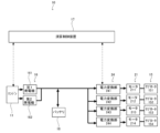
- FIG. 3 is a block diagram showing the connection configuration of the flight device 10.
- the flight device 10 mainly includes a calculation control section 17, an engine 11, a generator 16, a battery 18, a power conversion section 24, a motor 21, and a sub-rotor 15.
- the arithmetic control unit 17 includes a CPU, ROM, RAM, etc., and controls the behavior of each device constituting the flight device 10 based on inputs from various sensors and controllers not shown here. Further, the calculation control unit 17 is also a flight controller that controls the rotation speed of each rotor 14 and each sub-rotor 15 based on inputs from various sensors.
- the engine 11 operates based on an input signal from the arithmetic control unit 17, and generates kinetic energy for the flight device 10 to fly.
- the generator 16 is a device that generates electric power using part of the driving force of the engine 11, and includes a first generator 161 and a second generator 162.
- the first generator 161 is driven by the first engine section 111 of the engine 11, as described above.
- the second generator 162 is driven by the second engine section 112 of the engine 11.
- the battery 18 is interposed between the generator 16 and the power converter 24. Battery 18 is charged by generator 16. The power discharged from the battery 18 is supplied to a power converter 24, which will be described later.
- the power conversion unit 24 is provided corresponding to each sub-rotor 15.
- a converter and an inverter can be used that convert the AC power supplied from the second generator 162 into DC power and then convert it into AC power of a predetermined frequency.
- an inverter that converts DC power supplied from the battery 18 to a predetermined frequency can be employed.
- the power converter 24 includes a power converter 241 , a power converter 242 , a power converter 243 , and a power converter 244 .
- the motor 21 is provided corresponding to each sub-rotor 15 and includes a motor 211, a motor 212, a motor 213, and a motor 214.
- Motor 211, motor 212, motor 213, and motor 214 rotate at a predetermined speed by power supplied from power converter 241, power converter 242, power converter 243, and power converter 244, respectively.
- the sub-rotor 15 includes a sub-rotor 151, a sub-rotor 152, a sub-rotor 153, and a sub-rotor 154.
- Sub-rotor 151, sub-rotor 152, sub-rotor 153, and sub-rotor 154 are rotated by motor 211, motor 212, motor 213, and motor 214, respectively.
- the flight mode of the flight device 10 will be briefly explained.
- the flight device 10 is operated in a landing state, a takeoff state, a hovering state, an ascending and descending state, a horizontal movement state, and an emergency flight state.
- the flight device 10 In the landing state, the flight device 10 is on the ground. In this state, the engine 11 is not operating and the rotor 14 does not rotate.
- the flight device 10 leaves the ground plane and rises mainly due to the thrust generated by the rotation of the rotor 14.
- the flight device 10 rotates the rotor 14 using the driving force generated from the engine 11 based on instructions from the arithmetic control unit 17, thereby floating the flight device 10 at a predetermined position in the air.
- each sub-rotor 15 is rotating based on instructions from the calculation control unit 17.
- the arithmetic control unit 17 controls each power conversion unit 24 so that the rotational speed of each motor 21 and sub-rotor 15 is set to a predetermined value so that the flight device 10 can maintain a predetermined altitude and attitude.
- the flight device 10 In the ascending/descending state, the flight device 10 is raised or lowered by controlling the rotation speed of the engine 11. At this time, the arithmetic control unit 17 also controls each power conversion unit 24 to maintain the rotational speed of each motor 21 and sub-rotor 15 at a predetermined speed so that the flight device 10 can maintain a predetermined altitude and attitude. ing.
- the calculation control unit 17 brings the flight device 10 into a tilted state by controlling each power conversion unit 24 to control the rotation speed of each motor 21 and sub-rotor 15. At this time as well, the calculation control unit 17 rotates the rotor 14 at a predetermined speed by controlling the driving state of the engine 11.
- the arithmetic and control unit 17 forces the flying flight device 10 to land.
- FIG. 4 is a sectional view partially showing the engine 11 of the flight device 10 according to another embodiment.
- the engine 11 shown in FIG. 4 includes a third engine section 113 and a fourth engine section 114 in addition to the first engine section 111 and the second engine section 112. That is, the engine 11 has four engine parts.
- the first engine section 111 and the third engine section 113 rotate the aforementioned first rotor 141
- the second engine section 112 and the fourth engine section 114 rotate the aforementioned second rotor 142.
- the flight device 10 shown in FIG. 4 is the same as that shown in FIG. 1 except for the configuration of the engine 11.
- the third engine section 113 and the fourth engine section 114 are arranged to face each other in the left-right direction.
- the third engine section 113 includes a third piston 1131, a third crankshaft 1132, and a third connecting rod 1133 that rotatably connects the third piston 1131 and the third crankshaft 1132.
- the third crankshaft 1132 of the third engine section 113 is integrally continuous with the first crankshaft 1112 of the first engine section 111.
- the fourth engine section 114 includes a fourth piston 1141, a fourth crankshaft 1142, and a fourth connecting rod 1143 that rotatably connects the fourth piston 1141 and the fourth crankshaft 1142.
- the fourth crankshaft 1142 of the fourth engine section 114 is integrally continuous with the second crankshaft 1122 of the second engine section 112.
- the third piston 1131 and the fourth piston 1141 reciprocate inside the cylinder 26. Further, the third piston 1131 and the fourth piston 1141 share the combustion chamber 20. Also in such a configuration, as described above, the counter torque generated when the third engine section 113 and the fourth engine section 114 are operated can be almost completely eliminated. Further, the third engine section 113 performs intake, compression, combustion, and exhaust strokes in synchronization with the first engine section 111. Further, the fourth engine section 114 performs intake, compression, combustion, and exhaust strokes in synchronization with the second engine section 112.
- the output of the rotor 14 is improved by using the third engine section 113 and the fourth engine section 114 as power sources in addition to the first engine section 111 and the second engine section 112. be able to.
- FIG. 5 is a side view showing a flight device 27 according to another embodiment.
- the flight device 27 is a fixed-wing propeller aircraft having wings fixed to the fuselage.
- the flight device 27 has a rotor 14 at the tip of the fuselage.
- the rotor 14 is rotationally driven by the engine 11 located at the front end of the aircraft body.
- the configurations of the components that drive the engine 11 and the rotor 14 are similar to those of the flight device 10 described above.
- vibrations and torque generated by the operation of the engine 11 can be reduced, and stable flight and comfort of the flight device 27 can be improved.
- first drive transmission section 22 and the second drive transmission section 23 are illustrated as having belts, but other drive transmission mechanisms may be employed.
- a gear train or the like may be used as the first drive transmission section 22 and the second drive transmission section 23.
- the flying device 10 is a parallel hybrid drone, but the flying device 10 may be an engine-powered drone having only the rotor 14 and not having the sub-rotor 15. In this case, by controlling the pitch of the rotor 14, the attitude of the flight device 10 during flight can be controlled.
- Flight device 11 Engine 111 First engine part 1111 First piston 1112 First crankshaft 1113 First connecting rod 112 Second engine part 1121 Second piston 1122 Second crankshaft 1123 Second connecting rod 113 Third engine part 1131 3 piston 1132 3rd crankshaft 1133 3rd connecting rod 114 4th engine part 1141 4th piston 1142 4th crankshaft 1143 4th connecting rod 12 Transmission shaft 121 1st transmission shaft 122 2nd transmission shaft 13 Combustion chamber 14 Rotor 141 First rotor 142 Second rotor 15 Sub-rotor 151 Sub-rotor 152 Sub-rotor 153 Sub-rotor 154 Sub-rotor 16 Generator 161 First generator 162 Second generator 17 Arithmetic control section 18 Battery 19 Aircraft 20 Combustion chamber 21 Motor 211 Motor 212 Motor 213 Motor 214 Motor 22 First drive transmission section 221 First engine side pulley 222 First belt 223 First transmission shaft side pulley 23 Second drive transmission section 231 Second engine side pulley 232 Second belt 233 Second transmission shaft side pulley 24 Power conversion Part
Abstract
飛行時に発生する振動および反トルクを効果的に低減できる飛行装置を提供する。 飛行装置10は、エンジン11と、伝達軸12と、ロータ14と、を具備する。エンジン11は、第1エンジン部111と、第2エンジン部112と、を有する。伝達軸12は、第1エンジン部111により回転する第1伝達軸121と、第2エンジン部112により回転する第2伝達軸122と、を有する。ロータ14は、第1伝達軸121により回転する第1ロータ141と、第2伝達軸122により回転する第2ロータ142と、を有する。第1伝達軸121は、中空構造を有し、第2伝達軸122は、第1伝達軸121の内部に配置される。
Description
本発明は、飛行装置に関し、特に、エンジンにより駆動的にロータを駆動する飛行装置に関する。
従来から、無人で空中を飛行することが可能な飛行装置が知られている。このような飛行装置は、垂直軸回りに回転するロータの推力で、空中を飛行することを可能としている。
かかる飛行装置の適用分野としては、例えば、輸送分野、測量分野および撮影分野等が考えられる。このような分野に飛行装置を適用する場合は、測量機器や撮影機器を飛行装置に備え付ける。飛行装置をかかる分野に適用させることで、人が立ち入れない地域に飛行装置を飛行させ、そのような地域の輸送、撮影および測量を行うことができる。このような飛行装置に関する発明は、例えば、特許文献1や特許文献2に記載されている。
一般的な飛行装置では、飛行装置に搭載された蓄電池から供給される電力により、上記したロータは回転する。しかしながら、蓄電池による電力の供給ではエネルギの供給量が必ずしも十分ではないため、長時間に渡る連続飛行を実現するために、エンジンを搭載した飛行装置も出現している。このような飛行装置では、エンジンの駆動力で発電機を回転させ、発電機で発電された電力でロータを回転駆動している。かかる構成の飛行装置は、動力源からロータにエネルギが供給される経路に、エンジンと発電機とが直列的に接続されることから、シリーズ型ドローンとも称される。このような飛行装置を用いて撮影や測量を行うことで、広範囲な撮影や測量を行うことができる。エンジンが搭載された飛行装置は、例えば特許文献3に記載されている。また、エンジンの駆動力により機械的にメインロータを回転させ、モータによりサブロータを回転させるパラレル型ハイブリッドドローンも徐々に登場している。
しかしながら、前述した従前の飛行装置においては、駆動系の機構において改善の余地があった。
具体的には、従前の飛行装置であるドローンは、複数のモータまたはエンジンを有する場合が多いが、エンジンどうしの振動または反トルクが残存してしまい、これによりドローンの空中における位置姿勢の制御を正確に行うことが難しい課題がある。更に、発電機どうしの振動または反トルクが残存してしまうことによっても、同様の課題が発生する。
係る課題を解決するべく、ギアボックス等を駆動伝達系に配設することも考えられるが、係る構成であると、ドローン全体の構成の複雑化および重量化を招き、ドローンの連続飛行時間が短くなってしまう課題がある。
ロータが発生させるカウンタートルクは、二重反転ロータを採用することで打ち消すことが出来るが、係る場合、このような課題が顕著となる。
本発明は、上記の事情に鑑みてなされたものであり、その目的とするところは、飛行時に発生する振動および反トルクを効果的に低減できる飛行装置を提供することにある。
本発明の飛行装置は、エンジンと、伝達軸と、ロータと、を具備し、前記エンジンは、第1エンジン部と、第2エンジン部と、を有し、前記伝達軸は、前記第1エンジン部により回転する第1伝達軸と、前記第2エンジン部により回転する第2伝達軸と、を有し、前記ロータは、前記第1伝達軸により回転する第1ロータと、前記第2伝達軸により回転する第2ロータと、を有し、前記第1伝達軸は、中空構造を有し、前記第2伝達軸は、前記第1伝達軸の内部に配置されることを特徴とする。
また、本発明の飛行装置では、前記第1エンジン部と、前記第2エンジン部とは、互いが対向するように配置されることを特徴とする。
また、本発明の飛行装置では、前記第1エンジン部は、第1ピストンと、第1クランクシャフトと、前記第1ピストンと前記第1クランクシャフトとを回転可能に接続する第1コネクティングロッドと、を有し、前記第2エンジン部は、第2ピストンと、第2クランクシャフトと、前記第2ピストンと前記第2クランクシャフトとを回転可能に接続する第2コネクティングロッドと、を有し、前記第1伝達軸と前記第1クランクシャフトとは、第1駆動伝達部を介して駆動的に接続され、前記第2伝達軸と前記第2クランクシャフトとは、第2駆動伝達部を介して駆動的に接続されることを特徴とする。
また、本発明の飛行装置では、前記エンジンは、更に、第3エンジン部と、第4エンジン部と、を更に有し、前記第1エンジン部および前記第3エンジン部により、前記第1ロータが回転され、前記第2エンジン部および前記第4エンジン部により、前記第2ロータが回転されることを特徴とする。
また、本発明の飛行装置では、前記第1クランクシャフトと、前記第2クランクシャフトとは、回転方向が逆であることを特徴とする。
また、本発明の飛行装置では、第1発電機と、第2発電機と、を更に具備し、前記第1発電機は、前記第1エンジン部により駆動され、前記第2発電機は、前記第2エンジン部により駆動されることを特徴とする。
また、本発明の飛行装置では、サブロータと、を更に具備し、前記サブロータは、モータにより回転駆動されることを特徴とする。
本発明の飛行装置は、エンジンと、伝達軸と、ロータと、を具備し、前記エンジンは、第1エンジン部と、第2エンジン部と、を有し、前記伝達軸は、前記第1エンジン部により回転する第1伝達軸と、前記第2エンジン部により回転する第2伝達軸と、を有し、前記ロータは、前記第1伝達軸により回転する第1ロータと、前記第2伝達軸により回転する第2ロータと、を有し、前記第1伝達軸は、中空構造を有し、前記第2伝達軸は、前記第1伝達軸の内部に配置されることを特徴とする。本発明の飛行装置によれば、エンジンが第1エンジン部と第2エンジン部とを有することにより、各エンジン部により発生する振動およびトルクが相殺される。よって、飛行時においてエンジンから発生する振動等が低減され、飛行時における位置姿勢を安定化することができる。
また、本発明の飛行装置では、前記第1エンジン部と、前記第2エンジン部とは、互いが対向するように配置されることを特徴とする。本発明の飛行装置によれば、第1エンジン部と第2エンジン部とが対向配置されることで、振動、トルク等を相殺する効果を更に大きくすることができる。
また、本発明の飛行装置では、前記第1エンジン部は、第1ピストンと、第1クランクシャフトと、前記第1ピストンと前記第1クランクシャフトとを回転可能に接続する第1コネクティングロッドと、を有し、前記第2エンジン部は、第2ピストンと、第2クランクシャフトと、前記第2ピストンと前記第2クランクシャフトとを回転可能に接続する第2コネクティングロッドと、を有し、前記第1伝達軸と前記第1クランクシャフトとは、第1駆動伝達部を介して駆動的に接続され、前記第2伝達軸と前記第2クランクシャフトとは、第2駆動伝達部を介して駆動的に接続されることを特徴とする。本発明の飛行装置によれば、第1エンジン部と第2エンジン部の各部位が対向配置されることで、第1エンジン部および第2エンジン部が運転することにより発生する振動等を極めて小さくできる。
また、本発明の飛行装置では、前記エンジンは、更に、第3エンジン部と、第4エンジン部と、を更に有し、前記第1エンジン部および前記第3エンジン部により、前記第1ロータが回転され、前記第2エンジン部および前記第4エンジン部により、前記第2ロータが回転されることを特徴とする。本発明の飛行装置によれば、第3エンジン部および第4エンジン部に加えて、第3エンジン部および第4エンジン部も動力源として用いることにより、ロータの出力を向上させることができる。
また、本発明の飛行装置では、前記第1クランクシャフトと、前記第2クランクシャフトとは、回転方向が逆であることを特徴とする。本発明の飛行装置によれば、第1クランクシャフトの回転方向と、第2クランクシャフトの回転方向が逆であることにより、ロータの回転により発生するモーメントを相殺し、飛行時における安定性を更に向上できる。
また、本発明の飛行装置では、第1発電機と、第2発電機と、を更に具備し、前記第1発電機は、前記第1エンジン部により駆動され、前記第2発電機は、前記第2エンジン部により駆動されることを特徴とする。本発明の飛行装置によれば、第1発電機および第2発電機を駆動することで、飛行のための電気エネルギを得ることができる。
また、本発明の飛行装置では、サブロータと、を更に具備し、前記サブロータは、モータにより回転駆動されることを特徴とする。本発明の飛行装置によれば、サブロータにより飛行時の位置姿勢の制御を更に効果的に行うことができる。
以下、図を参照して本形態の飛行装置の構成を説明する。以下の説明では、同一の構成を有する部位には同一の符号を付し、繰り返しの説明は省略する。尚、以下の説明では上下前後左右の各方向を用いるが、これらの各方向は説明の便宜のためである。また、飛行装置10は、ドローンとも称され、詳細にはパラレル型ハイブリッドドローンとも称される。パラレル型ハイブリッドドローンとは、エンジンにより機械的に駆動されるロータと、モータにより駆動されるロータとを有するドローンである。
図1は、飛行装置10を上方から見た平面図である。
飛行装置10は、エンジン11と、伝達軸12と、ロータ14と、を主要に具備する。飛行装置10は、電気的駆動系と、機械的駆動系との並列した2つの駆動系を有するパラレル型ハイブリッドドローンである。電気的駆動系は、後述するモータ21およびサブロータ15を回転させる駆動系である。機械的駆動系は、後述するロータ14を回転させる駆動系である。
機体19は、飛行装置10を構成する各機器を支える本体であり、合成樹脂、金属またはこれらの複合材から成る。
ロータ14は、回転することにより機体19が浮遊するための駆動力を発生させる。ロータ14は、第1ロータ141と、第2ロータ142と、を有する。第1ロータ141と第2ロータ142とは、二重反転プロペラを構成している。第1ロータ141と第2ロータ142とは、回転方向が逆であり、回転速度は同等である。例えば、上面視において、第1ロータ141は反時計回りに回転し、第2ロータ142は時計回りに回転する。ロータ14は、エンジン11の駆動力により機械的に回転するメインロータである。
飛行装置10は、サブロータ15を有する。サブロータ15は、サブロータ151ないしサブロータ154を有する。サブロータ15は、飛行装置10の飛行時における位置姿勢を制御するべく回転する。
サブロータ151は、機体19の左側前方に配置され、後述するモータ211により回転する。サブロータ152は、機体19の左側後方に配置され、後述するモータ212により回転する。サブロータ153は、機体19の右側前方に配置され、後述するモータ213により回転する。サブロータ154は、機体19の右側後方に配置され、後述するモータ214により回転する。
図2は、飛行装置10を示す断面図である。
飛行装置10は、機体19の内部にエンジン11が収納され、機体19の上方にロータ14が配設される。
エンジン11は、第1エンジン部111と、第2エンジン部112と、を有する。
第1エンジン部111は、第1ピストン1111と、第1クランクシャフト1112と、第1ピストン1111と第1クランクシャフト1112とを回転可能に接続する第1コネクティングロッド1113と、を有する。第1エンジン部111の第1クランクシャフト1112は、機体19の上面から上方に向かって突出している。
第2エンジン部112は、第2ピストン1121と、第2クランクシャフト1122と、第2ピストン1121と、第2クランクシャフト1122とを回転可能に接続する第2コネクティングロッド1123と、を有する。第2エンジン部112の第2クランクシャフト1122は、機体19の上面から上方に向かって突出している。
第1エンジン部111の第1ピストン1111と、第2エンジン部41の第2ピストン1121で、燃焼室13を共有する。換言すると、第1ピストン1111と第2ピストン1121とは、連通する一つのシリンダ25の内部を往復運動する。よって、第1ピストン1111および第2ピストン1121が、中心部に向かって同時にストロークすることで、ストローク量を少なくしつつ、燃焼室13における混合ガスの高膨張比をとることができる。
ここでは図示していないが、エンジン11には、燃焼室13から連通する容積空間が形成されており、この容積空間に点火プラグが配置されている。また、燃焼室13には、ここでは図示しない吸気口および排気口が形成されており、ガソリンなどの燃料を含む混合気が吸気口から燃焼室13に導入され、燃焼後の排気ガスが排気口を経由して燃焼室13から外部に排気される。
上記した構成のエンジン11は、次のように動作する。先ず、吸込行程では、第1ピストン1111および第2ピストン1121がシリンダ25の内部で中央部から外側に向かって移動することで、燃料と空気との混合物である混合気をシリンダ25の内部に導入する。次に、圧縮行程では、回転する第1クランクシャフト1112および第2クランクシャフト1122の慣性により、第1ピストン1111および第2ピストン1121が中央部に向かって押し出され、シリンダ25の内部で混合気が圧縮される。次に、燃焼行程では、図示しない点火プラグが燃焼室13で点火することで、シリンダ25の内部で混合気が燃焼し、これにより第1ピストン1111および第2ピストン1121が、下死点である外側の端部まで押し出される。その後、排気行程では、回転する第1クランクシャフト1112および第2クランクシャフト1122の慣性により、第1ピストン1111および第2ピストン1121が内側に押し出され、シリンダ25の内部に存在する燃焼後のガスは、外部に排出される。
エンジン11では、一つのシリンダ25の内部で往復運動する2つの第1ピストン1111および第2ピストン1121で、ストロークを分割することができる。よって、通常のガソリンエンジンと比較して、混合ガスの圧縮比を大きくすることができる。また、シリンダ25の内部で第1ピストン1111および第2ピストン1121が対向するので、一般的なエンジンで必要とされるシリンダヘッドが不要と成り、エンジン11の構成が簡素であり且つ軽量とされている。また、エンジン11を構成している各部材、即ち、第1ピストン1111および第2ピストン1121、第1クランクシャフト1112および第2クランクシャフト1122等が対向して対称的に配置され、かつ同期するように動作している。このことから、エンジン11の各部材から発生する振動が相殺され、エンジン11全体から外部に発生する振動を少なくすることができる。また、エンジン11を構成する各部材が回転することにより発生するトルクやモーメントも、ほぼ全てが相殺される。
よって、このような構造のエンジン11を飛行装置10に搭載することで、飛行装置10の小型化、軽量化、低振動化、カウンタートルク低減を達成することができる。特に、低振動化により、姿勢制御、モータ出力制御などの演算制御装置やGPSセンサ等の精密機器への悪影響を防止することが出来る。また、飛行装置10が輸送する配送荷物が振動で損傷してしまうことを防止することができる。
エンジン11には、ここでは図示しない逆転同期機構が備えられている。逆転同期機構は、第1クランクシャフト1112と第2クランクシャフト1122との回転方向を逆とする。更に、逆転同期機構は、第1ピストン1111と第2ピストン1121の往復運動を同期する。よって、エンジン11において、原理的に、第1クランクシャフト1112と第2クランクシャフト1122とでは、回転方向は逆とされている。従って、第1クランクシャフト1112と駆動的に接続される各部材と、第2クランクシャフト1122と駆動的に接続される各部材とは、専用の反転機構を設けることなく、逆方向に回転するようになる。よって、図2に示した、第1ロータ141と第2ロータ142とは、専用の反転機構を設けなくても、等しい回転速度で、逆方向に回転するようになる。また、第1クランクシャフト1112および第2クランクシャフト1122の各々により回転駆動される他の各部材も、専用の反転機構を設けなくても、等しい回転速度で、逆方向に回転するようになる。
第1発電機161は、機体19の上方側に配置され、第1クランクシャフト1112により回転駆動される。具体的には、第1発電機161は、図示しない回転子を有し、この回転子が第1クランクシャフト1112に対して回転不可能に接続される。係る構成により、第1クランクシャフト1112と共に、第1発電機161に内蔵された回転子が回転することにより、第1発電機161による発電が行われ、電気エネルギが発生する。
第2発電機162の構成は、第1発電機161と同様である。具体的には、第2発電機162は、機体19の上方側に配置され、第2クランクシャフト1122により回転駆動される。第2発電機162は、図示しない回転子を有し、この回転子が第2クランクシャフト1122に対して回転不可能に接続される。係る構成により、第2クランクシャフト1122と共に、第2発電機162に内蔵された回転子が回転することにより、第2発電機162による発電が行われ、電気エネルギが発生する。
伝達軸12は、エンジン11から発生する駆動力により回転することで、前述したロータ14を回転させる略軸状の部材である。伝達軸12は、第1エンジン部111により回転する第1伝達軸121と、第2エンジン部112により回転する第2伝達軸122と、を有する。伝達軸12は、後述するように、メカニカルに同軸反転する機構を有する。
第1伝達軸121は、その上端が第1ロータ141に接続されることにより、第1ロータ141を回転させる。第1伝達軸121は、機体19の上面に対して、回転可能に配設されている。第1伝達軸121の下端近傍は、後述する第1駆動伝達部22を介して、第1クランクシャフト1112と駆動的に接続されている。即ち、第1エンジン部111により発生した回転駆動力は、第1クランクシャフト1112および第1駆動伝達部22を経由して、第1伝達軸121に伝達される。
第2伝達軸122は、その上端が第2ロータ142に接続されることにより、第2ロータ142を回転させる。第2ロータ142は、機体19の上面に対して、回転可能に配設されている。第2伝達軸122の下端近傍は、後述する第2駆動伝達部23を介して、第2クランクシャフト1122と駆動的に接続されている。即ち、第2エンジン部112により発生した回転駆動力は、第2クランクシャフト1122および第2駆動伝達部23を経由して、第2伝達軸122に伝達される。
第1伝達軸121は、中空構造を有し、第2伝達軸122は、第1伝達軸121の内部に配置される。具体的には、第1伝達軸121の内部には略円柱形状の空間が形成され、第2伝達軸122は係る空間を貫通している。また、第2伝達軸122の上端は、第1伝達軸121の上端よりも上方側に配置される。更に、第2伝達軸122の下端は、第1伝達軸121の下端よりも下方側に配置される。即ち、第1伝達軸121と第2伝達軸122とは、同軸反転構造を形成している。
第1駆動伝達部22は、第1クランクシャフト1112の回転駆動力を、第1伝達軸121に伝達する。具体的には、第1駆動伝達部22は、第1エンジン側プーリ221と、第1ベルト222と、第1伝達軸側プーリ223と、を有する。第1エンジン側プーリ221は、第1クランクシャフト1112の上端部に、相対回転不能に接続される。第1伝達軸側プーリ223は、第1伝達軸121の下端に、相対回転不能に接続される。第1ベルト222は、第1エンジン側プーリ221と第1伝達軸側プーリ223との間に架設される。係る構成により、飛行装置10の飛行時において、第1エンジン部111が運転されることにより、第1クランクシャフト1112および第1エンジン側プーリ221が回転する。また、第1エンジン側プーリ221の回転駆動力が、第1ベルト222を介して、第1伝達軸側プーリ223に伝達する。これにより、第1伝達軸121および第1ロータ141が回転する。
第2駆動伝達部23の構成は、第1駆動伝達部22と同様である。即ち、第2駆動伝達部23は、第2クランクシャフト1122の回転駆動力を、第2伝達軸122に伝達する。具体的には、第2駆動伝達部23は、第2エンジン側プーリ231と、第2ベルト232と、第2伝達軸側プーリ233と、を有する。第2エンジン側プーリ231は、第2クランクシャフト1122の上端部に、相対回転不能に接続される。第2伝達軸側プーリ233は、第2伝達軸122の中間部に、相対回転不能に接続される。第2ベルト232は、第2エンジン側プーリ231と第2伝達軸側プーリ233との間に架設される。係る構成により、飛行装置10の飛行時において、第2エンジン部112が運転されることにより、第2クランクシャフト1122および第2エンジン側プーリ231が回転する。また、第2エンジン側プーリ231の回転駆動力が、第2ベルト232を介して、第2伝達軸側プーリ233に伝達する。これにより、第2伝達軸122および第2ロータ142が回転する。
図3は、飛行装置10の接続構成を示すブロック図である。
飛行装置10は、演算制御部17と、エンジン11と、発電機16と、バッテリ18と、電力変換部24と、モータ21と、サブロータ15と、を主要に有する。
演算制御部17は、CPU、ROM、RAM等を有し、ここでは図示しない各種センサやコントローラからの入力に基づいて、飛行装置10を構成する各機器の挙動を制御する。また、演算制御部17は、各種センサからの入力に基づいて、各ロータ14および各サブロータ15の回転数を制御するフライトコントローラでもある。
エンジン11は、演算制御部17からの入力信号に基づいて動作し、飛行装置10が飛行するための運動エネルギを発生させる。
発電機16は、エンジン11の駆動力の一部を用いて電力を発生する装置であり、第1発電機161および第2発電機162を有する。第1発電機161は、前述したように、エンジン11の第1エンジン部111により駆動される。第2発電機162は、エンジン11の第2エンジン部112により駆動される。
バッテリ18は、発電機16と電力変換部24との間に介装される。バッテリ18は、発電機16により充電される。バッテリ18から放電された電力は、後述する電力変換部24に供給される。
電力変換部24は、個々のサブロータ15に対応して設けられる。電力変換部24としては、第2発電機162から供給される交流電力を、一旦直流化した後に所定の周波数の交流電力に変換するコンバータおよびインバータを採用できる。また、電力変換部24としては、バッテリ18から供給される直流電力を所定の周波数に変換するインバータを採用できる。具体的には、電力変換部24は、電力変換部241、電力変換部242、電力変換部243および電力変換部244を有する。
モータ21は、個々のサブロータ15に対応して設けられ、モータ211、モータ212、モータ213およびモータ214を有する。モータ211、モータ212、モータ213およびモータ214は、夫々、電力変換部241、電力変換部242、電力変換部243および電力変換部244から供給される電力により所定の速度で回転する。
サブロータ15は、前述したように、サブロータ151、サブロータ152、サブロータ153およびサブロータ154を有する。サブロータ151、サブロータ152、サブロータ153およびサブロータ154は、夫々、モータ211、モータ212、モータ213およびモータ214により回転する。
飛行装置10の飛行態様を簡単に説明する。飛行装置10は、着陸状態、離陸状態、ホバリング状態、昇降状態、水平移動状態、緊急飛行状態で稼働される。
着陸状態では、飛行装置10は接地している。この状態では、エンジン11は稼働しておらず、ロータ14は回転しない。
離陸状態では、飛行装置10は、主に、ロータ14の回転により発生する推力により、接地面から離れて上昇する。
ホバリング状態では、飛行装置10は、演算制御部17からの指示に基づいて、エンジン11から発生する駆動力によりロータ14を回転させ、飛行装置10を空中の所定位置に浮遊させる。この際、演算制御部17からの指示に基づいて、各サブロータ15は回転している。演算制御部17は、飛行装置10が所定の高度および姿勢を維持できるように、各電力変換部24を制御することで、各モータ21およびサブロータ15の回転速度を所定のものにしている。
昇降状態では、エンジン11の回転数を制御することで、飛行装置10を上昇または下降させる。この際も、演算制御部17は、飛行装置10が所定の高度および姿勢を維持できるように、各電力変換部24を制御することで、各モータ21およびサブロータ15の回転速度を所定のものにしている。
水平移動状態では、演算制御部17は、各電力変換部24を制御することで、各モータ21およびサブロータ15の回転数を制御することにより、飛行装置10を傾斜状態にする。この際にも、演算制御部17は、エンジン11の駆動状態を制御することで、ロータ14を所定速度で回転させる。
緊急飛行状態では、演算制御部17は、飛行している飛行装置10を強制的に着陸させる。
図4は、他形態に係る飛行装置10のエンジン11を部分的に示す断面図である。図4に示すエンジン11では、第1エンジン部111および第2エンジン部112に加えて、第3エンジン部113および第4エンジン部114を有する。即ち、エンジン11は、4つのエンジン部を有する。第1エンジン部111および第3エンジン部113により、前述した第1ロータ141が回転され、第2エンジン部112および第4エンジン部114により、前述した第2ロータ142が回転される。また、図4に示す飛行装置10は、エンジン11の構成以外は、図1に示したものと同様である。
第3エンジン部113と、第4エンジン部114とは、左右方向に関して対向配置されている。
第3エンジン部113は、第3ピストン1131と、第3クランクシャフト1132と、第3ピストン1131と第3クランクシャフト1132とを回転可能に接続する第3コネクティングロッド1133と、を有する。ここで、第3エンジン部113の第3クランクシャフト1132は、第1エンジン部111の第1クランクシャフト1112と一体的に連続している。
第4エンジン部114は、第4ピストン1141と、第4クランクシャフト1142と、第4ピストン1141と第4クランクシャフト1142とを回転可能に接続する第4コネクティングロッド1143と、を有する。ここで、第4エンジン部114の第4クランクシャフト1142は、第2エンジン部112の第2クランクシャフト1122と一体的に連続している。
第3ピストン1131および第4ピストン1141は、シリンダ26の内部で往復運動する。また、第3ピストン1131と第4ピストン1141とは、燃焼室20を共有している。係る構成においても、前述と同様に、第3エンジン部113および第4エンジン部114が運転されることで発生するカウンタートルクを、ほぼ完全に解消することができる。更に、第3エンジン部113は、第1エンジン部111と同期して、吸気、圧縮、燃焼および排気の各行程を行う。また、第4エンジン部114は、第2エンジン部112と同期して、吸気、圧縮、燃焼および排気の各行程を行う。
図4に示す飛行装置10では、第1エンジン部111および第2エンジン部112に加えて、第3エンジン部113および第4エンジン部114も動力源として用いることにより、ロータ14の出力を向上させることができる。
図5は、他形態に係る飛行装置27を示す側面図である。
飛行装置27は、胴体に固定された翼部を有する固定翼プロペラ機である。飛行装置27は、機体の先端にロータ14を有する。ロータ14は、機体の前端に配置されたエンジン11により回転駆動される。エンジン11およびロータ14を駆動させる構成機器の構成は、前述した飛行装置10と同様である。
飛行装置27にエンジン11を配置することにより、エンジン11が運転されることにより発生する振動やトルクを減少させ、飛行装置27の安定飛行および快適性を向上できる。
以上、本発明の実施形態について説明したが、本発明は、これに限定されるものではなく、本発明の要旨を逸脱しない範囲で変更が可能である。また、前述した各形態は相互に組み合わせることが可能である。
図2を参照して、第1駆動伝達部22および第2駆動伝達部23として、ベルトを備えたものを例示したが、他の駆動伝達機構を採用し得る。例えば、第1駆動伝達部22および第2駆動伝達部23として、ギア列等を採用し得る。
図2を参照して、飛行装置10は、パラレル型ハイブリッドドローンであったが、飛行装置10は、ロータ14のみを有し、サブロータ15を有さないエンジン式ドローンであっても良い。この場合、ロータ14をピッチ制御することで、飛行装置10の飛行時における姿勢制御を行える。
10 飛行装置
11 エンジン
111 第1エンジン部
1111 第1ピストン
1112 第1クランクシャフト
1113 第1コネクティングロッド
112 第2エンジン部
1121 第2ピストン
1122 第2クランクシャフト
1123 第2コネクティングロッド
113 第3エンジン部
1131 第3ピストン
1132 第3クランクシャフト
1133 第3コネクティングロッド
114 第4エンジン部
1141 第4ピストン
1142 第4クランクシャフト
1143 第4コネクティングロッド
12 伝達軸
121 第1伝達軸
122 第2伝達軸
13 燃焼室
14 ロータ
141 第1ロータ
142 第2ロータ
15 サブロータ
151 サブロータ
152 サブロータ
153 サブロータ
154 サブロータ
16 発電機
161 第1発電機
162 第2発電機
17 演算制御部
18 バッテリ
19 機体
20 燃焼室
21 モータ
211 モータ
212 モータ
213 モータ
214 モータ
22 第1駆動伝達部
221 第1エンジン側プーリ
222 第1ベルト
223 第1伝達軸側プーリ
23 第2駆動伝達部
231 第2エンジン側プーリ
232 第2ベルト
233 第2伝達軸側プーリ
24 電力変換部
241 電力変換部
242 電力変換部
243 電力変換部
244 電力変換部
25 シリンダ
26 シリンダ
27 飛行装置
Claims (7)
- エンジンと、伝達軸と、ロータと、を具備し、
前記エンジンは、第1エンジン部と、第2エンジン部と、を有し、
前記伝達軸は、前記第1エンジン部により回転する第1伝達軸と、前記第2エンジン部により回転する第2伝達軸と、を有し、
前記ロータは、前記第1伝達軸により回転する第1ロータと、前記第2伝達軸により回転する第2ロータと、を有し、
前記第1伝達軸は、中空構造を有し、
前記第2伝達軸は、前記第1伝達軸の内部に配置されることを特徴とする飛行装置。 - 前記第1エンジン部と、前記第2エンジン部とは、互いが対向するように配置されることを特徴とする請求項1に記載の飛行装置。
- 前記第1エンジン部は、第1ピストンと、第1クランクシャフトと、前記第1ピストンと前記第1クランクシャフトとを回転可能に接続する第1コネクティングロッドと、を有し、
前記第2エンジン部は、第2ピストンと、第2クランクシャフトと、前記第2ピストンと前記第2クランクシャフトとを回転可能に接続する第2コネクティングロッドと、を有し、
前記第1伝達軸と前記第1クランクシャフトとは、第1駆動伝達部を介して駆動的に接続され、
前記第2伝達軸と前記第2クランクシャフトとは、第2駆動伝達部を介して駆動的に接続されることを特徴とする請求項1または請求項2に記載の飛行装置。 - 前記エンジンは、更に、第3エンジン部と、第4エンジン部と、を更に有し、
前記第1エンジン部および前記第3エンジン部により、前記第1ロータが回転され、
前記第2エンジン部および前記第4エンジン部により、前記第2ロータが回転されることを特徴とする請求項1または請求項2に記載の飛行装置。 - 前記第1クランクシャフトと、前記第2クランクシャフトとは、回転方向が逆であることを特徴とする請求項3に記載の飛行装置。
- 第1発電機と、第2発電機と、を更に具備し、
前記第1発電機は、前記第1エンジン部により駆動され、
前記第2発電機は、前記第2エンジン部により駆動されることを特徴とする請求項1または請求項2に記載の飛行装置。 - サブロータと、を更に具備し、
前記サブロータは、モータにより回転駆動されることを特徴とする請求項1または請求項2に記載の飛行装置。
Applications Claiming Priority (2)
| Application Number | Priority Date | Filing Date | Title |
|---|---|---|---|
| JP2022-065773 | 2022-04-12 | ||
| JP2022065773A JP2023156106A (ja) | 2022-04-12 | 2022-04-12 | 飛行装置 |
Publications (1)
| Publication Number | Publication Date |
|---|---|
| WO2023199801A1 true WO2023199801A1 (ja) | 2023-10-19 |
Family
ID=88329601
Family Applications (1)
| Application Number | Title | Priority Date | Filing Date |
|---|---|---|---|
| PCT/JP2023/013970 WO2023199801A1 (ja) | 2022-04-12 | 2023-04-04 | 飛行装置 |
Country Status (2)
| Country | Link |
|---|---|
| JP (1) | JP2023156106A (ja) |
| WO (1) | WO2023199801A1 (ja) |
Citations (5)
| Publication number | Priority date | Publication date | Assignee | Title |
|---|---|---|---|---|
| US7712701B1 (en) * | 2006-02-10 | 2010-05-11 | Lockheed Martin Corporation | Unmanned aerial vehicle with electrically powered, counterrotating ducted rotors |
| EP3492377A1 (en) * | 2016-07-26 | 2019-06-05 | Obshchestvo S Ogranichennoj Otvetstvennostyu "Avianovatsii" | Vertical take-off and landing aircraft |
| JP2021167198A (ja) * | 2020-09-17 | 2021-10-21 | 株式会社石川エナジーリサーチ | エンジン搭載自立型飛行装置 |
| WO2021221156A1 (ja) * | 2020-04-30 | 2021-11-04 | ヤマハ発動機株式会社 | 飛行体用エンジン発電機ユニット及び飛行体 |
| US20210403148A1 (en) * | 2017-03-15 | 2021-12-30 | Bell Textron Inc. | Vibration Isolation Systems for Compound Helicopters |
-
2022
- 2022-04-12 JP JP2022065773A patent/JP2023156106A/ja active Pending
-
2023
- 2023-04-04 WO PCT/JP2023/013970 patent/WO2023199801A1/ja unknown
Patent Citations (5)
| Publication number | Priority date | Publication date | Assignee | Title |
|---|---|---|---|---|
| US7712701B1 (en) * | 2006-02-10 | 2010-05-11 | Lockheed Martin Corporation | Unmanned aerial vehicle with electrically powered, counterrotating ducted rotors |
| EP3492377A1 (en) * | 2016-07-26 | 2019-06-05 | Obshchestvo S Ogranichennoj Otvetstvennostyu "Avianovatsii" | Vertical take-off and landing aircraft |
| US20210403148A1 (en) * | 2017-03-15 | 2021-12-30 | Bell Textron Inc. | Vibration Isolation Systems for Compound Helicopters |
| WO2021221156A1 (ja) * | 2020-04-30 | 2021-11-04 | ヤマハ発動機株式会社 | 飛行体用エンジン発電機ユニット及び飛行体 |
| JP2021167198A (ja) * | 2020-09-17 | 2021-10-21 | 株式会社石川エナジーリサーチ | エンジン搭載自立型飛行装置 |
Also Published As
| Publication number | Publication date |
|---|---|
| JP2023156106A (ja) | 2023-10-24 |
Similar Documents
| Publication | Publication Date | Title |
|---|---|---|
| US20230042223A1 (en) | Engine-mounted autonomous flying device | |
| US10899461B2 (en) | Vertical lift by series hybrid-propulsion | |
| US10647442B2 (en) | Single engine, asymmetrical vertical take-off and landing (VTOL) aircraft | |
| KR101340409B1 (ko) | 하이브리드 무인비행체 | |
| CN106043679A (zh) | 多轴动力源无人飞行设备 | |
| JP6969821B2 (ja) | エンジン搭載自立型飛行装置 | |
| CN113492989A (zh) | 具有混合推进的飞行器 | |
| WO2023058721A1 (ja) | 飛行装置 | |
| JP2019112050A (ja) | 航空機 | |
| WO2023199801A1 (ja) | 飛行装置 | |
| JP2022172974A (ja) | 無人飛行体のエンジン装置 | |
| WO2023079900A1 (ja) | 飛行装置 | |
| WO2023189644A1 (ja) | 飛行装置および飛行装置制御方法 | |
| WO2022172315A1 (ja) | 動力装置および移動用推進装置 | |
| JP6770767B2 (ja) | エンジン搭載自立型飛行装置 | |
| JP7399521B2 (ja) | 飛行装置 | |
| CN106043680A (zh) | 航空发动机 | |
| JP7438589B1 (ja) | 飛行装置 | |
| CN218537120U (zh) | 一种双螺旋桨固定翼无人机 | |
| US11685537B1 (en) | Parallel hybrid propulsion system | |
| WO2023176782A1 (ja) | 飛行装置 | |
| US20230303274A1 (en) | Systems and Methods for Controlling Engine Speed and/or Pitch of Propulsion Members for Aerial Vehicles | |
| WO2023243299A1 (ja) | 飛行装置 | |
| CN106184731A (zh) | 具有多轴动力源的航空器 | |
| RU2260546C1 (ru) | Летательный аппарат вертикального взлета и посадки с аэродинамическим подъемно-тянущим движителем |
Legal Events
| Date | Code | Title | Description |
|---|---|---|---|
| 121 | Ep: the epo has been informed by wipo that ep was designated in this application |
Ref document number: 23788220 Country of ref document: EP Kind code of ref document: A1 |