WO2023199732A1 - ノイズ低減具及びワイヤハーネス - Google Patents
ノイズ低減具及びワイヤハーネス Download PDFInfo
- Publication number
- WO2023199732A1 WO2023199732A1 PCT/JP2023/012057 JP2023012057W WO2023199732A1 WO 2023199732 A1 WO2023199732 A1 WO 2023199732A1 JP 2023012057 W JP2023012057 W JP 2023012057W WO 2023199732 A1 WO2023199732 A1 WO 2023199732A1
- Authority
- WO
- WIPO (PCT)
- Prior art keywords
- noise reduction
- magnetic body
- electric wires
- plane
- winding
- Prior art date
- Legal status (The legal status is an assumption and is not a legal conclusion. Google has not performed a legal analysis and makes no representation as to the accuracy of the status listed.)
- Ceased
Links
Images






Classifications
-
- H—ELECTRICITY
- H01—ELECTRIC ELEMENTS
- H01B—CABLES; CONDUCTORS; INSULATORS; SELECTION OF MATERIALS FOR THEIR CONDUCTIVE, INSULATING OR DIELECTRIC PROPERTIES
- H01B7/00—Insulated conductors or cables characterised by their form
- H01B7/0045—Cable-harnesses
-
- H—ELECTRICITY
- H01—ELECTRIC ELEMENTS
- H01B—CABLES; CONDUCTORS; INSULATORS; SELECTION OF MATERIALS FOR THEIR CONDUCTIVE, INSULATING OR DIELECTRIC PROPERTIES
- H01B7/00—Insulated conductors or cables characterised by their form
- H01B7/17—Protection against damage caused by external factors, e.g. sheaths or armouring
- H01B7/18—Protection against damage caused by wear, mechanical force or pressure; Sheaths; Armouring
- H01B7/184—Sheaths comprising grooves, ribs or other projections
-
- H—ELECTRICITY
- H01—ELECTRIC ELEMENTS
- H01F—MAGNETS; INDUCTANCES; TRANSFORMERS; SELECTION OF MATERIALS FOR THEIR MAGNETIC PROPERTIES
- H01F1/00—Magnets or magnetic bodies characterised by the magnetic materials therefor; Selection of materials for their magnetic properties
- H01F1/01—Magnets or magnetic bodies characterised by the magnetic materials therefor; Selection of materials for their magnetic properties of inorganic materials
- H01F1/03—Magnets or magnetic bodies characterised by the magnetic materials therefor; Selection of materials for their magnetic properties of inorganic materials characterised by their coercivity
- H01F1/032—Magnets or magnetic bodies characterised by the magnetic materials therefor; Selection of materials for their magnetic properties of inorganic materials characterised by their coercivity of hard-magnetic materials
- H01F1/10—Magnets or magnetic bodies characterised by the magnetic materials therefor; Selection of materials for their magnetic properties of inorganic materials characterised by their coercivity of hard-magnetic materials non-metallic substances, e.g. ferrites, e.g. [(Ba,Sr)O(Fe2O3)6] ferrites with hexagonal structure
- H01F1/11—Magnets or magnetic bodies characterised by the magnetic materials therefor; Selection of materials for their magnetic properties of inorganic materials characterised by their coercivity of hard-magnetic materials non-metallic substances, e.g. ferrites, e.g. [(Ba,Sr)O(Fe2O3)6] ferrites with hexagonal structure in the form of particles
- H01F1/113—Magnets or magnetic bodies characterised by the magnetic materials therefor; Selection of materials for their magnetic properties of inorganic materials characterised by their coercivity of hard-magnetic materials non-metallic substances, e.g. ferrites, e.g. [(Ba,Sr)O(Fe2O3)6] ferrites with hexagonal structure in the form of particles in a bonding agent
- H01F1/117—Flexible bodies
-
- H—ELECTRICITY
- H01—ELECTRIC ELEMENTS
- H01F—MAGNETS; INDUCTANCES; TRANSFORMERS; SELECTION OF MATERIALS FOR THEIR MAGNETIC PROPERTIES
- H01F1/00—Magnets or magnetic bodies characterised by the magnetic materials therefor; Selection of materials for their magnetic properties
- H01F1/01—Magnets or magnetic bodies characterised by the magnetic materials therefor; Selection of materials for their magnetic properties of inorganic materials
- H01F1/03—Magnets or magnetic bodies characterised by the magnetic materials therefor; Selection of materials for their magnetic properties of inorganic materials characterised by their coercivity
- H01F1/12—Magnets or magnetic bodies characterised by the magnetic materials therefor; Selection of materials for their magnetic properties of inorganic materials characterised by their coercivity of soft-magnetic materials
- H01F1/34—Magnets or magnetic bodies characterised by the magnetic materials therefor; Selection of materials for their magnetic properties of inorganic materials characterised by their coercivity of soft-magnetic materials non-metallic substances, e.g. ferrites
- H01F1/36—Magnets or magnetic bodies characterised by the magnetic materials therefor; Selection of materials for their magnetic properties of inorganic materials characterised by their coercivity of soft-magnetic materials non-metallic substances, e.g. ferrites in the form of particles
- H01F1/37—Magnets or magnetic bodies characterised by the magnetic materials therefor; Selection of materials for their magnetic properties of inorganic materials characterised by their coercivity of soft-magnetic materials non-metallic substances, e.g. ferrites in the form of particles in a bonding agent
- H01F1/375—Flexible bodies
-
- H—ELECTRICITY
- H02—GENERATION; CONVERSION OR DISTRIBUTION OF ELECTRIC POWER
- H02G—INSTALLATION OF ELECTRIC CABLES OR LINES, OR OF COMBINED OPTICAL AND ELECTRIC CABLES OR LINES
- H02G3/00—Installations of electric cables or lines or protective tubing therefor in or on buildings, equivalent structures or vehicles
- H02G3/02—Details
- H02G3/04—Protective tubing or conduits, e.g. cable ladders or cable troughs
-
- H—ELECTRICITY
- H05—ELECTRIC TECHNIQUES NOT OTHERWISE PROVIDED FOR
- H05K—PRINTED CIRCUITS; CASINGS OR CONSTRUCTIONAL DETAILS OF ELECTRIC APPARATUS; MANUFACTURE OF ASSEMBLAGES OF ELECTRICAL COMPONENTS
- H05K9/00—Screening of apparatus or components against electric or magnetic fields
Definitions
- the present invention relates to a noise reduction device and a wire harness.
- the noise reduction device is a member made of a magnetic material, and includes a magnetic material as a component that is attached to an electric wire through which a noise current flows to reduce the emission of radiated noise from the electric wire to the outside.
- a noise countermeasure a sheet-like magnetic material is wrapped around a plurality of wires bundled together, and the magnetic material is used to reduce noise in the plurality of wires.
- a noise reduction device has been disclosed that reduces the emission of radiated noise from a current-carrying electric wire to the outside.
- an object of the present invention is to provide a noise reduction device and a wire harness that can maintain the distance between electric wires.
- the noise reduction device includes a windable sheet-like or band-like magnetic material, and the magnetic material has a winding shape with respect to one plane disposed inside the winding shape. It is characterized in that electric wires whose axial directions are aligned with the direction of the rotation axis are arranged side by side around the axis of the winding shaft.
- the wire harness according to the present invention includes a plurality of electric wires and a noise reduction device that reduces emission of radiation noise emitted from each of the electric wires to the outside, and the noise reduction device can be wound.
- the magnetic body is wound with an electric wire whose axial direction is aligned with the winding axis direction of the winding shape, around one plane arranged inside the winding shape. It is characterized by being arranged side by side around the axis of rotation.
- the noise reduction device and wire harness according to the present invention can reduce the emission of radiated noise from each electric wire to the outside. Since this noise reduction tool and wire harness can maintain a longer distance between the respective electric wires than conventional ones, it is possible to reduce the influence of radiated noise between them.
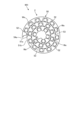
- FIG. 1 is a schematic diagram of a wire harness in which a noise reduction device according to an embodiment is assembled, viewed in the axial direction.
- FIG. 2 is a schematic side view of the wire harness in which the noise reduction device of the embodiment is assembled.
- FIG. 3 is a perspective view schematically showing the noise reduction device of the embodiment.
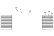
- FIG. 4 is a plan view schematically showing the noise reduction tool of the embodiment before winding together with the electric wire.
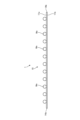
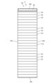
- FIG. 5 is a schematic diagram of the noise reduction device of the embodiment viewed from one plane side.
- FIG. 6 is a schematic diagram of another form of adhesive in the noise reduction tool of the embodiment, viewed from one plane side.
- FIG. 7 is a schematic diagram of a wire harness in which a modified noise reduction device is assembled, viewed in the axial direction.
- FIG. 8 is a perspective view schematically showing a modified example of a noise reduction tool.
- FIG. 9 is a plan view schematically showing a modified example of the noise reduction device together with the electric wire before winding.
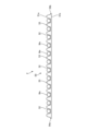
- FIG. 10 is a schematic diagram of a modified example of the noise reduction device viewed from one plane side.
- FIG. 11 is a schematic diagram of another form of adhesive in a modified noise reduction tool, viewed from one plane side.
- FIGS. 1 to 6 One embodiment of a noise reduction device and a wire harness according to the present invention will be described based on FIGS. 1 to 6.
- the reference numeral 1 shown in FIGS. 1 to 6 indicates the noise reduction tool of this embodiment.
- This noise reduction tool 1 is attached to a plurality of electric wires We through which noise current flows, and reduces the emission of radiated noise from each electric wire We to the outside, and also reduces the radiation noise between the respective electric wires We. Reduce impact.
- the symbol WH shown in FIGS. 1 and 2 indicates a wire harness in which the noise reduction tool 1 is assembled to a plurality of electric wires We.
- One or more noise reduction tools 1 are provided depending on the length of the electric wire We.
- This wire harness WH is mounted on an electric vehicle (not shown) such as a BEV (Battery Electric Vehicle) or a PHEV (Plug-in Hybrid Electric Vehicle), for example.
- this wire harness WH is installed between a secondary battery for driving an electric vehicle and a secondary battery for auxiliary equipment, and between a DC/DC converter and a secondary battery for auxiliary equipment interposed between the two. make a physical and electrical connection between the two.
- This wire harness WH is responsible for feeding power from the driving secondary battery to the auxiliary secondary battery when charging the auxiliary secondary battery.
- this wire harness WH is used, for example, in a charging system (not shown) for charging a secondary battery for driving and a secondary battery for auxiliary equipment of an electric vehicle.
- This charging system is configured for normal charging or quick charging, regardless of whether it is for business or home use.
- This charging system includes an external power source, a charger body supplied with power from the external power source, and a charging cable with a connector for feeding power from the charger body to the vehicle side.
- a charging cable with a connector is used by a worker when supplying power, and includes a charging cable provided with at least a plurality of power lines (wires We) and a charging connector attached to one terminal of the charging cable. and.
- some charging systems perform charging control while communicating between the vehicle and the charger body during power supply.
- the charging cable in this case is also provided with a communication signal line responsible for the communication.
- a three-phase AC power source is used as the external power source, and an AC/DC converter that converts the AC voltage to DC voltage is housed in the casing of the charger body. ing.
- the charging cable with a connector supplies the converted power to the vehicle side.
- the charging cable with a connector is assembled in advance to the charger main body, and may constitute the charger together with the charger main body.
- This charging cable with a connector is routed from the charger main body side to the vehicle side when charging, and the charging connector is physically and electrically connected to the connector of the electric vehicle (vehicle side connector).
- the charging cable with a connector may be a separate component that is housed in the luggage compartment of a vehicle, and a power source side connector may be attached to the other end of the charging cable.
- the charger body constitutes a charger.
- the power supply side connector is physically and electrically connected to the connector on the charger body, and the charging connector is physically and electrically connected to the vehicle side connector. Connect.
- This charging system is provided with an internal charging cable that electrically connects the AC/DC converter side and the charging cable side within the casing of the charger main body.
- This internal charging cable includes at least a plurality of internal power lines (electric wires We), and the internal power lines electrically connect the AC/DC converter side and the charging cable side. Therefore, in this charging system, the wire harness WH of this embodiment includes the noise reduction device 1 attached to the plurality of internal power lines (electric wires We) in this internal charging cable. Note that when performing the above communication during charging, the internal charging cable is also provided with an internal communication signal line.
- the wire harness WH of this embodiment is a charging cable with a connector, in which the noise reduction device 1 is attached to a plurality of power lines (electric wires We).
- the noise reduction tool 1 includes a windable sheet-like or band-like magnetic material 10 (FIGS. 1 to 6).
- the magnetic body 10 is made of a ferromagnetic material and is molded with flexibility. Ferrite or the like is used as the ferromagnetic material.
- This magnetic body 10 has a winding shape and is arranged with electric wires We arranged around the winding axis, the axial direction of which is aligned with the winding axis direction of the winding shape, on one plane 11a arranged on the inside. ( Figure 1).
- this noise reduction device 1 a plurality of electric wires We with the same axial direction are aligned along one plane 11a in a direction orthogonal to the axial direction with respect to one plane 11a of a sheet-like or band-like magnetic body 10. Line them up one by one.
- the magnetic body 10 is wound together with the respective electric wires We in a tassel-wound shape with one plane 11a inside (FIG. 1).
- the magnetic body 10 is interposed between the electric wires We that are adjacent in the radial direction of the wound shape, and a space can be maintained between the electric wires We. Therefore, this noise reduction tool 1 can not only reduce the emission of radiated noise from each electric wire We to the outside, but also reduce the influence of radiated noise between radially adjacent electric wires We. can.
- this noise reduction tool when looking at the respective electric wires We around the winding axis, the distance between adjacent electric wires We around this axis is found to be close in some cases and far away in others. For this reason, in this noise reduction device 1, a plurality of electric wires We with the same axial direction are arranged one by one at intervals in a direction perpendicular to the axial direction with respect to one plane 11a of the magnetic body 10. This is desirable. At that time, in this noise reduction tool 1, in order to maintain the distance between the electric wires We, for example, an adhesive (for example, an adhesive 22 described later) provided on one plane 11a of the magnetic body 10 is used. , it is desirable to attach each electric wire We to this one plane 11a.
- an adhesive for example, an adhesive 22 described later
- the magnetic body 10 is wound together with each of the electric wires We in a coiled form with one plane 11a inside (FIG. 1). Thereby, in this noise reduction tool 1, the magnetic body 10 is interposed between the electric wires We that are adjacent in the radial direction of the wound shape, and a space can be maintained between the electric wires We. Furthermore, in this noise reduction device 1, since the plurality of electric wires We are arranged side by side around the winding axis with a space between them, it is possible to provide a space between the electric wires We adjacent to each other around the axis. can.
- this noise reduction tool 1 can not only reduce the emission of radiated noise from each electric wire We to the outside, but also reduce the influence of radiated noise between radially adjacent electric wires We. In addition, the influence of radiation noise between adjacent electric wires We around the winding axis can be reduced.
- the noise reduction tool 1 includes, for example, one or more binding bands to be wrapped around the winding-shaped magnetic body 10 depending on the length in the winding axis direction. (not shown).
- the noise reduction tool 1 may use an adhesive instead of or together with the binding band.
- An adhesive 21 is provided to adhere to the other flat surface 11b of the magnetic body 10.
- the noise reduction device 1 shown in FIG. 6 has a winding shape in the magnetic body 10, and one plane 11a of each of the ends 14c and 14d perpendicular to the winding axis direction has at least the other plane of the magnetic body.
- An adhesive 22 is provided to adhere to 11b. Therefore, the noise reduction tool 1 can have the function of suppressing displacement of the electric wire We with respect to the one plane 11a and the function of holding it by the adhesive 22. Due to its holding function, this noise reduction tool 1 can improve the assembly workability until the winding work of the sheet-like or band-like magnetic material 10 is finished.
- the noise reduction tool 1 of this embodiment can reduce the emission of radiation noise from each electric wire We to the outside.
- This noise reduction tool 1 can maintain a distance between the respective electric wires We. For this reason, this noise reduction tool 1 reduces the influence of radiated noise between the individual wires We, compared to a device in which a sheet-like magnetic material is wrapped around a plurality of wires We that are bundled together. It can be reduced. Furthermore, this noise reduction tool 1 can be applied to a plurality of electric wires We even if the electric wires We have different diameters and electric wires We have different lengths.
- the wire harness WH of this embodiment includes this noise reduction tool 1, and can produce the same effects as those obtained by this noise reduction tool 1.
- Reference numeral 2 shown in FIGS. 7 to 11 indicates a noise reduction device of this modification. Similar to the noise reduction tool 1 of the embodiment described above, this noise reduction tool 2 is attached to a plurality of electric wires We through which noise current flows, and reduces the emission of radiated noise from each electric wire We to the outside. At the same time, the influence of radiation noise between the respective electric wires We is reduced. In the wire harness WH of this modification, the noise reduction tool 2 is assembled to a plurality of electric wires We. One or more noise reduction tools 2 are provided depending on the length of the electric wire We.
- the noise reduction tool 2 of this modification includes a windable sheet-like or band-like magnetic body 50 (FIGS. 7 to 11). Similar to the magnetic body 10 of the embodiment, this magnetic body 50 is made of a ferromagnetic material such as ferrite and is made of a flexible material, and is wound together with a plurality of electric wires We in a sash-like shape.
- This magnetic body 50 has a groove portion 52 for each electric wire We that can accommodate one electric wire We with the axial direction aligned with the winding axis direction of the wound shape in one plane 51a disposed inside the magnetic body 50. ( Figures 7 to 11).
- this noise reduction tool 2 one electric wire We is accommodated in each groove 52 in the sheet-like or band-like magnetic material 50 (FIG. 9).
- the magnetic body 50 is wound together with the respective electric wires We in a tassel-wound shape with one plane 51a inside (FIG. 6).
- this noise reduction tool 2 it is possible to provide a space between the respective electric wires We. Therefore, this noise reduction tool 2 can not only reduce the emission of radiated noise from each electric wire We to the outside, but also reduce the influence of radiated noise between each electric wire We.
- this noise reduction device 2 by forming all the grooves 52 (groove width and groove depth) into a uniform shape, it is necessary to specify the accommodation location in the groove 52 for electric wires We having the same diameter. Since there is no wire, it is possible to improve the workability of assembling between the magnetic body 50 and the electric wire We.
- the groove depth of the groove portion 52 be deeper than the diameter of the electric wire We.
- peaks 53 higher than the wire diameter are interposed between the respective wires We accommodated in adjacent grooves 52 (FIGS. 7 to 9). Therefore, this noise reduction tool 2 can further reduce the influence of radiation noise between the respective electric wires We.
- the groove portion 52 may be formed in a shape into which the electric wire We is inserted and sandwiched between the peak portions 53 on both sides.
- this noise reduction tool 2 by fitting the electric wire We into the groove 52, the electric wire We can be kept in the groove 52 until the winding work of the sheet-like or strip-like magnetic material 50 is finished. It can be kept as is. Thereby, this noise reduction tool 2 can improve the assembling workability until the winding work is finished.
- the noise reduction tool 2 includes, for example, one or more binding bands to be wrapped around the winding-shaped magnetic body 50 depending on the length in the winding axis direction. (not shown).
- the noise reduction tool 2 may use an adhesive instead of or together with the binding band.
- An adhesive 61 is provided to adhere to the other flat surface 51b of the magnetic body 10.
- the noise reduction tool 2 shown in FIG. 11 has a winding shape in the magnetic body 50, and one plane 51a of each end 54c, 54d perpendicular to the direction of the winding axis, at least the other plane of the magnetic body.
- An adhesive 62 is provided to adhere to 51b.
- the noise reduction tool 2 can have a function of preventing displacement of the electric wire We with respect to the groove 52 and a holding function using the adhesive 62 in the groove 52 .
- the noise reduction tool 2 can improve the assembly workability until the winding work of the sheet-like or band-like magnetic material 50 is completed without fitting the electric wire We into the groove 52.
- the adhesive 62 is represented by a chain line in the figure.
- the noise reduction tool 2 of this modification can reduce the emission of radiation noise emitted from each electric wire We to the outside.
- This noise reduction tool 2 can maintain a distance between the respective electric wires We by the groove portions 52. For this reason, this noise reduction tool 2 reduces the influence of radiated noise between the individual wires We, compared to a device in which a sheet-like magnetic material is wrapped around a plurality of wires We that are bundled together. It can be reduced.
- the noise reduction device 2 can It can be applied to the electric wire We.
- the wire harness WH of this modification includes this noise reduction tool 2, and can produce the same effects as those obtained by this noise reduction tool 2.
- the noise reduction device 1 and wire harness WH of the embodiment described so far and the noise reduction device 2 and wire harness WH of the modified example can obtain the effects with a simple and inexpensive configuration, so they can be used in electric vehicles and By applying it to charging systems (regardless of whether it is for normal charging or rapid charging), it will contribute to the spread of electric vehicles and charging systems.
- the noise reduction device 1 and wire harness WH of the embodiment and the noise reduction device 2 and wire harness WH of the modification are particularly useful in charging systems for rapid charging and electric vehicles capable of rapid charging using the charging system. Become something.
Landscapes
- Engineering & Computer Science (AREA)
- Power Engineering (AREA)
- Structural Engineering (AREA)
- Dispersion Chemistry (AREA)
- Architecture (AREA)
- Civil Engineering (AREA)
- Chemical & Material Sciences (AREA)
- Microelectronics & Electronic Packaging (AREA)
- Shielding Devices Or Components To Electric Or Magnetic Fields (AREA)
- Hard Magnetic Materials (AREA)
- Soft Magnetic Materials (AREA)
- Details Of Indoor Wiring (AREA)
- Coils Or Transformers For Communication (AREA)
Abstract
Description
本発明に係るノイズ低減具及びワイヤハーネスの実施形態の1つを図1から図6に基づいて説明する。
図7から図11に示す符号2は、本変形例のノイズ低減具を示す。このノイズ低減具2は、前述した実施形態のノイズ低減具1と同じように、ノイズ電流の流れる複数本の電線Weに取り付けて、それぞれの電線Weから出た放射ノイズの外部への放出を低減させると共に、それぞれの電線Weの間での放射ノイズの影響を軽減させる。本変形例のワイヤハーネスWHは、このノイズ低減具2が複数本の電線Weに組み付けられたものである。ノイズ低減具2は、電線Weの長さに応じて1つ又は複数設ける。
10,50 磁性体
11a,51a 一方の平面
11b,51b 他方の平面
52 溝部
14a,14b,14c,14d,54a,54b,54c,54d 端部
21,22,61,62 接着剤
We 電線
WH ワイヤハーネス
Claims (6)
- 巻回可能なシート状又は帯状の磁性体を備え、
前記磁性体は、巻回形状で内側に配置される一方の平面に対して、前記巻回形状の巻回軸方向に軸線方向を合わせた電線を巻回軸の軸周りに並べて配置するノイズ低減具。 - 前記磁性体は、前記一方の平面に、前記電線を前記巻回軸方向に軸線方向を合わせて1本ずつ収容可能な前記電線毎の溝部を有する請求項1に記載のノイズ低減具。
- 前記磁性体における前記巻回形状で前記巻回軸方向に沿う両端部の内の最外方に位置する端部の前記一方の平面に、前記磁性体の他方の平面に接着させる接着剤を設ける請求項1又は2に記載のノイズ低減具。
- 前記磁性体における前記巻回形状で前記巻回軸方向に直交するそれぞれの端部の前記一方の平面に、少なくとも前記磁性体の他方の平面に接着させる接着剤を設ける請求項1又は2に記載のノイズ低減具。
- 複数本の電線と、
それぞれの前記電線から出た放射ノイズの外部への放出を低減させるノイズ低減具と、
を備え、
前記ノイズ低減具は、巻回可能なシート状又は帯状の磁性体を備え、
前記磁性体は、巻回形状で内側に配置される一方の平面に対して、前記巻回形状の巻回軸方向に軸線方向を合わせた電線を巻回軸の軸周りに並べて配置するワイヤハーネス。 - 前記磁性体は、前記一方の平面に、前記電線を前記巻回軸方向に軸線方向を合わせて1本ずつ収容可能な前記電線毎の溝部を有する請求項5に記載のワイヤハーネス。
Priority Applications (3)
| Application Number | Priority Date | Filing Date | Title |
|---|---|---|---|
| DE112023001861.8T DE112023001861T5 (de) | 2022-04-11 | 2023-03-25 | Rauschreduktionseinrichtung und Kabelbaum |
| CN202380022017.4A CN118743324A (zh) | 2022-04-11 | 2023-03-25 | 降噪件和线束 |
| US18/799,073 US20240404725A1 (en) | 2022-04-11 | 2024-08-09 | Noise reduction tool and wire harness |
Applications Claiming Priority (2)
| Application Number | Priority Date | Filing Date | Title |
|---|---|---|---|
| JP2022-064953 | 2022-04-11 | ||
| JP2022064953A JP7538169B2 (ja) | 2022-04-11 | 2022-04-11 | ノイズ低減具及びワイヤハーネス |
Related Child Applications (1)
| Application Number | Title | Priority Date | Filing Date |
|---|---|---|---|
| US18/799,073 Continuation US20240404725A1 (en) | 2022-04-11 | 2024-08-09 | Noise reduction tool and wire harness |
Publications (1)
| Publication Number | Publication Date |
|---|---|
| WO2023199732A1 true WO2023199732A1 (ja) | 2023-10-19 |
Family
ID=88329479
Family Applications (1)
| Application Number | Title | Priority Date | Filing Date |
|---|---|---|---|
| PCT/JP2023/012057 Ceased WO2023199732A1 (ja) | 2022-04-11 | 2023-03-25 | ノイズ低減具及びワイヤハーネス |
Country Status (5)
| Country | Link |
|---|---|
| US (1) | US20240404725A1 (ja) |
| JP (1) | JP7538169B2 (ja) |
| CN (1) | CN118743324A (ja) |
| DE (1) | DE112023001861T5 (ja) |
| WO (1) | WO2023199732A1 (ja) |
Families Citing this family (2)
| Publication number | Priority date | Publication date | Assignee | Title |
|---|---|---|---|---|
| JP2025125995A (ja) | 2024-02-16 | 2025-08-28 | 三星エスディアイ株式会社 | 複合炭素質導電材及び非水電解質二次電池 |
| CN120636907B (zh) * | 2025-07-25 | 2026-01-27 | 东莞市成佳电线电缆有限公司 | 一种长距离工业机器人耐弯扭拖链电缆 |
Citations (1)
| Publication number | Priority date | Publication date | Assignee | Title |
|---|---|---|---|---|
| JPH10145073A (ja) * | 1996-11-13 | 1998-05-29 | Advanced Display:Kk | ノイズ低減用ケーブルカバーシートおよびそれを備えてなる液晶表示装置 |
Family Cites Families (2)
| Publication number | Priority date | Publication date | Assignee | Title |
|---|---|---|---|---|
| JP6398255B2 (ja) | 2014-03-27 | 2018-10-03 | 株式会社オートネットワーク技術研究所 | 電磁シールド部材 |
| JP7146668B2 (ja) | 2019-02-21 | 2022-10-04 | ラピスセミコンダクタ株式会社 | 容量センサ回路及び半導体集積回路 |
-
2022
- 2022-04-11 JP JP2022064953A patent/JP7538169B2/ja active Active
-
2023
- 2023-03-25 WO PCT/JP2023/012057 patent/WO2023199732A1/ja not_active Ceased
- 2023-03-25 CN CN202380022017.4A patent/CN118743324A/zh active Pending
- 2023-03-25 DE DE112023001861.8T patent/DE112023001861T5/de active Pending
-
2024
- 2024-08-09 US US18/799,073 patent/US20240404725A1/en active Pending
Patent Citations (1)
| Publication number | Priority date | Publication date | Assignee | Title |
|---|---|---|---|---|
| JPH10145073A (ja) * | 1996-11-13 | 1998-05-29 | Advanced Display:Kk | ノイズ低減用ケーブルカバーシートおよびそれを備えてなる液晶表示装置 |
Also Published As
| Publication number | Publication date |
|---|---|
| US20240404725A1 (en) | 2024-12-05 |
| JP7538169B2 (ja) | 2024-08-21 |
| CN118743324A (zh) | 2024-10-01 |
| JP2023155562A (ja) | 2023-10-23 |
| DE112023001861T5 (de) | 2025-02-20 |
Similar Documents
| Publication | Publication Date | Title |
|---|---|---|
| US9663046B2 (en) | Electric wire and wire harness | |
| EP2711937B1 (en) | Shielding wire | |
| WO2023199732A1 (ja) | ノイズ低減具及びワイヤハーネス | |
| JP5986812B2 (ja) | ワイヤハーネス | |
| KR20140125855A (ko) | 전선의 배색 구조, 및 외장부재붙이 전선 | |
| JP7537351B2 (ja) | ホルダ、及びワイヤハーネス | |
| JP6080341B2 (ja) | ワイヤハーネス | |
| JP2019032933A (ja) | ワイヤハーネス | |
| WO2013018812A1 (ja) | ワイヤハーネス | |
| JP6838576B2 (ja) | ワイヤハーネス | |
| JP7497692B2 (ja) | ワイヤハーネス | |
| JP2012085442A (ja) | 電線保護具及びワイヤハーネス | |
| US20230271570A1 (en) | Wire harness | |
| WO2020183944A1 (ja) | ワイヤハーネス | |
| JP2023155560A (ja) | コネクタ付き充電ケーブル及び充電器 | |
| WO2023199733A1 (ja) | ノイズ低減具及びワイヤハーネス | |
| JP2023155561A (ja) | ノイズ低減具及びワイヤハーネス | |
| JP3243908B2 (ja) | ワイヤハーネス用結束具およびワイヤハーネスの結束方法 | |
| JP7848929B2 (ja) | ワイヤハーネス | |
| JP2012242667A (ja) | ワイヤハーネスの配索構造 | |
| JP2022144697A (ja) | シールド外装および該シールド外装に備えられたワイヤーハーネス | |
| WO2021132020A1 (ja) | 配索部材及びワイヤハーネス | |
| JP2012085441A (ja) | 電線保護具及びワイヤハーネス |
Legal Events
| Date | Code | Title | Description |
|---|---|---|---|
| 121 | Ep: the epo has been informed by wipo that ep was designated in this application |
Ref document number: 23788152 Country of ref document: EP Kind code of ref document: A1 |
|
| WWE | Wipo information: entry into national phase |
Ref document number: 202380022017.4 Country of ref document: CN |
|
| WWE | Wipo information: entry into national phase |
Ref document number: 202447062185 Country of ref document: IN |
|
| WWE | Wipo information: entry into national phase |
Ref document number: 112023001861 Country of ref document: DE |
|
| WWP | Wipo information: published in national office |
Ref document number: 112023001861 Country of ref document: DE |
|
| 122 | Ep: pct application non-entry in european phase |
Ref document number: 23788152 Country of ref document: EP Kind code of ref document: A1 |