WO2023199634A1 - バルーンカテーテル用バルーン - Google Patents
バルーンカテーテル用バルーン Download PDFInfo
- Publication number
- WO2023199634A1 WO2023199634A1 PCT/JP2023/007705 JP2023007705W WO2023199634A1 WO 2023199634 A1 WO2023199634 A1 WO 2023199634A1 JP 2023007705 W JP2023007705 W JP 2023007705W WO 2023199634 A1 WO2023199634 A1 WO 2023199634A1
- Authority
- WO
- WIPO (PCT)
- Prior art keywords
- balloon
- film thickness
- distal
- thinnest
- longitudinal axis
- Prior art date
- Legal status (The legal status is an assumption and is not a legal conclusion. Google has not performed a legal analysis and makes no representation as to the accuracy of the status listed.)
- Ceased
Links
Images


Classifications
-
- A—HUMAN NECESSITIES
- A61—MEDICAL OR VETERINARY SCIENCE; HYGIENE
- A61M—DEVICES FOR INTRODUCING MEDIA INTO, OR ONTO, THE BODY; DEVICES FOR TRANSDUCING BODY MEDIA OR FOR TAKING MEDIA FROM THE BODY; DEVICES FOR PRODUCING OR ENDING SLEEP OR STUPOR
- A61M25/00—Catheters; Hollow probes
- A61M25/10—Balloon catheters
Definitions
- the present invention relates to a balloon for a balloon catheter and a balloon catheter equipped with the same.
- Angioplasty which involves inserting a balloon catheter into the narrowed part of a blood vessel and expanding the balloon to expand the blood vessel and ensure blood flow, is widely practiced as a minimally invasive therapy.
- Angioplasty is used, for example, to treat diseases such as myocardial infarction caused by stenosis in the coronary arteries of the heart, or to treat stenosis that occurs in a shunt for dialysis.
- a balloon used in a balloon catheter usually has a cylindrical shape with narrowed distal and proximal sides, and the cylindrical portion having the largest diameter dilates the blood vessel.
- Patent Documents 1 to 3 disclose balloons in which pressure resistance is attempted to be improved by controlling the molecular orientation of the resin constituting the balloon.
- the membrane main body of the balloon has an intermediate layer containing a non-elastomer, and an outer layer and an inner layer containing an elastomer disposed on the outer surface and inner surface of the intermediate layer, and the intermediate layer It is disclosed that by setting the average film thickness of the balloon to 30% to 70% of the average film thickness of the entire balloon, a balloon with improved compliance and a good balance between pressure resistance and passage performance was obtained.
- an object of the present invention is to provide a balloon for a balloon catheter that can easily suppress circumferential cracking even if the balloon is destroyed.
- An embodiment of the balloon for a balloon catheter of the present invention that can solve the above problems has a proximal end and a distal end in the longitudinal direction, and a straight pipe part and a balloon closer to the straight pipe part.
- the balloon has a proximal tapered part located on the side of the balloon, and a distal tapered part located on the distal side of the straight tube part, the balloon having a proximal tapered part located on the side of the straight tube,
- the film thickness is measured at 8 points equally spaced apart by 45° in the 360° circumferential direction of the balloon, and when the average of the 8 points is taken as the average film thickness at the predetermined position, the film thickness in the longitudinal axis direction is measured.
- the proximal end of the straight tube section is at the 0% position
- the distal end is at the 100% position
- the balloon has the thinnest average film thickness Tx in the central section from the 30% position to the 70% position.
- a position having a distance of 1/4 of the length of the straight pipe portion on the proximal side from the thinnest position X is a proximal position P
- a position far from the thinnest position A position located 1/4 of the length of the straight pipe portion on the proximal side is defined as a distal position D
- the amount of change in film thickness divided by 1/4 of the length is 2.0 ⁇ 10 ⁇ 4 or less
- the average film thickness Tx
- the coefficient of variation of the film thickness at the eight points is preferably 1.5 ⁇ 10 ⁇ 2 or more. This makes it easier to prevent stress concentration from occurring in the circumferential direction when internal pressure is applied to the balloon.
- the position where the average film thickness is the thinnest is the same as the thinnest position X in the entire section of the straight pipe section from the 0% position to the 100% position among the predetermined positions.
- the present invention also provides a balloon catheter including the balloon for a balloon catheter described above.
- FIG. 1 is a plan view of a balloon catheter according to an embodiment of the present invention.
- FIG. 2 is a plan view of the balloon of the balloon catheter shown in FIG. 1;
- FIG. 3 is a plan view of the balloon when cracking occurs in the longitudinal axis direction.
- FIG. 3 is a plan view when a circumferential crack occurs in the balloon.
- FIG. 3 is a plan view when a cross-shaped crack occurs in the balloon.
- 3 is a sectional view taken along the line VI-VI of the balloon shown in FIG. 2.
- FIG. It is a figure of the film thickness measurement result of the balloon concerning one embodiment of the present invention. It is a graph showing the average film thickness along the longitudinal axis direction of the balloon according to one embodiment of the present invention. It represents the stress strain curve of polyamide resin.
- FIG. 2 is a cross-sectional view showing a parison placed in a mold according to an embodiment of the present invention.
- FIG. 3 is a cross-sectional view showing a state in a first stretching step according to an embodiment of the present invention. It is a sectional view showing the state in the second stretching process concerning one embodiment of the present invention. It is a sectional view showing the state after the 2nd stretching process concerning one embodiment of the present invention ends.
- 3 is a diagram showing the results of measuring the film thickness of the balloon obtained in Example 1.
- FIG. 3 is a diagram showing the results of measuring the film thickness of another balloon obtained in Example 1.
- FIG. 3 is a diagram showing the results of measuring the film thickness of yet another balloon obtained in Example 1.
- FIG. 3 is a diagram showing the results of measuring the film thickness of yet another balloon obtained in Example 1.
- FIG. 3 is a diagram showing the results of measuring the film thickness of yet another balloon obtained in Example 1.
- FIG. 3 is a diagram showing the results of measuring the film thickness of a balloon obtained in Comparative Example 1.
- FIG. 3 is a diagram showing the results of measuring the film thickness of another balloon obtained in Comparative Example 1.
- FIG. 3 is a diagram showing the film thickness measurement results of yet another balloon obtained in Comparative Example 1.
- FIG. 3 is a diagram showing the film thickness measurement results of yet another balloon obtained in Comparative Example 1.
- FIG. 3 is a diagram showing the film thickness measurement results of yet another balloon obtained in Comparative Example 1.
- the balloon for a balloon catheter has a proximal end and a distal end in the longitudinal axis direction, and includes a straight tube section and a proximal end located on the proximal side of the straight tube section.
- the film thickness at 8 points equally spaced by 45° is measured, and the average of the above 8 points is taken as the average film thickness at a given position.
- the proximal end of the straight pipe part is 0%
- the position where the balloon has the thinnest average film thickness Tx in the central section from the 30% position to the 70% position is the thinnest position X, and the distal end is the 100% position.
- the proximal position P is a position 1/4 of the length of the straight tube part away from the thinnest position.
- the amount of film thickness change obtained by dividing the difference between the average film thickness Tp and the average film thickness Tx at the proximal position P by 1/4 of the length of the straight pipe section, with the position as the distal position D, and The amount of change in film thickness obtained by dividing the difference between the average film thickness Td and the average film thickness Tx at the distal position D by 1/4 of the length of the straight pipe part is 2.0 ⁇ 10 -4 or less in both cases.
- the average film thickness Tx is 30 ⁇ m or less.
- the balloon for a balloon catheter according to the embodiment of the present invention has an average film thickness Tx at the thinnest position X of 30 ⁇ m or less, and an average film thickness at the thinnest position X in the central section of the balloon. Since the average film thickness Tp at the proximal position P and the average film thickness Td at the distal position D with respect to Tx are both 2.0 ⁇ 10 -4 or less, the maximum thickness of the central section of the balloon is Since the film thickness change in the region along the longitudinal axis from the thin position X can be made gentler, it is possible to suppress the concentration of stress in the circumferential direction and prevent circumferential cracks. Thereby, the risk of a torn piece of the balloon for a balloon catheter remaining in the body can be avoided, and safe treatment using the balloon catheter is possible.
- FIG. 1 is a plan view of a balloon catheter according to an embodiment of the present invention.
- FIG. 2 is a plan view of the balloon of the balloon catheter shown in FIG. 3 to 5 are plan views showing examples of cracks occurring in the balloon for a balloon catheter according to an embodiment of the present invention, in which longitudinal cracks, circumferential cracks, and cross-shaped cracks occur, respectively.
- FIG. 6 is a sectional view taken along the line VI-VI of the balloon shown in FIG. 2, and is a diagram illustrating a method for determining the average film thickness at a predetermined position.
- FIG. 7 is a diagram showing the results of measuring the film thickness of a balloon according to an embodiment of the present invention.
- FIG. 8 is a graph showing the average film thickness at each position along the longitudinal axis of the balloon according to an embodiment of the present invention.
- the balloon for a balloon catheter may be simply referred to as a "balloon.”
- the balloon 20 is used for the balloon catheter 1.
- Balloon 20 is connected to the distal side of shaft 3 and can be expanded by introducing fluid through the lumen of shaft 3 and deflated by expelling fluid. Fluid can be introduced or expelled using an indeflator (balloon pressurizer) to control expansion and deflation of the balloon 20.
- the fluid may be a pressurized fluid pressurized by a pump or the like.
- the balloon 20 has a longitudinal axis direction x, a circumferential direction z along the outer edge of the balloon 20 in a section perpendicular to the longitudinal axis direction x, and a centroid of the outer edge of the balloon 20 in a cross section perpendicular to the longitudinal axis direction x. It has a radial direction y connecting the points on the outer edge.
- the direction toward the user's hand with respect to the longitudinal axis direction x is referred to as the proximal side
- the direction opposite to the proximal side, that is, the direction toward the treatment target side is referred to as the distal side.
- the balloon 20 has a proximal end and a distal end in the longitudinal axis direction x, and includes a straight tube section 23 and a proximal tapered section 22 located on the proximal side of the straight tube section 23. , and a distal tapered portion 24 located on the distal side of the straight tube portion 23.
- the straight tube portions 23 have approximately the same diameter in the longitudinal axis direction x, they may have different diameters in the longitudinal axis direction x.
- the proximal tapered portion 22 and the distal tapered portion 24 are formed so that their diameters decrease as they move away from the straight pipe portion 23.
- the straight tube part 23 has the maximum diameter, when the balloon 20 is expanded in a diseased area such as a stenosis, the straight tube part 23 comes into sufficient contact with the lesion, making it easy to perform treatments such as expansion of the lesion. can. Furthermore, since the proximal tapered portion 22 and the distal tapered portion 24 are reduced in diameter, when the balloon 20 is deflated, the outer diameters of the proximal and distal ends of the balloon 20 are reduced. Since the height difference between the shaft 3 and the balloon 20 can be reduced, the balloon 20 can be easily inserted into the body cavity.
- the balloon 20 may have a proximal sleeve portion 21 on the proximal side of the proximal tapered portion 22 and a distal sleeve portion 25 on the distal side of the distal tapered portion 24. At least a portion of the proximal sleeve portion 21 and the distal sleeve portion 25 may be fixed to the shaft 3.
- the straight tube section 23 of the balloon 20 has its proximal end set at a 0% position L 0 and its distal end set at a 100% position L 100 in the longitudinal axis direction x.
- it has a central section 23C from 30% position L 30 to 70% position L 70 , an end on the proximal side of the central section 23C, and an end on the distal side of the central section 23C. ing.
- the thinnest part of the balloon 20 is usually located in the central section 23C, so when the internal pressure of the balloon 20 becomes overpressurized, Cracks may occur in the central section 23C.
- the stress applied in the circumferential direction z is twice the stress applied in the longitudinal axis direction x, so in a normal thin cylindrical shell, as shown in FIG. Tends to crack in the longitudinal direction. For this reason, even in conventional balloons, cracking in the longitudinal axis direction is theoretically dominant.
- FIG. 6 is a sectional view taken along the line VI-VI of the balloon 20 shown in FIG. 2, and is a sectional view perpendicular to the longitudinal axis direction x at a predetermined position of the straight tube portion 23.
- the average film thickness of the balloon 20 at a predetermined position in the longitudinal axis direction x is determined by measuring the film thickness at eight points equally spaced by 45 degrees out of 360 degrees in the circumferential direction z of the balloon 20, and calculating the film thickness at the eight points. It is determined by finding the average of That is, when point a in FIG.
- the points where the central angle ⁇ is 45°, 90°, 135°, 180°, 225°, 270°, and 315° are Point b, point c, point d, point e, point f, point g, and point h, respectively, and measure the film thickness at eight points from point a to point h at predetermined positions in the longitudinal axis direction x, and from point a to point h.
- FIG. 7 shows an example of a chart obtained by actual measurement.
- the horizontal axis in FIG. 7 represents the position of the straight pipe portion 23 in the longitudinal axis direction x, with 0 at the left end corresponding to the 0% position L 0 and 150 at the right end corresponding to the 100% position L 100 .
- the vertical axis in FIG. 7 represents the central angle ⁇ in the circumferential direction z, and the gray scale represents the film thickness (unit: mm).
- the lines in the chart of FIG. 7 are isovalue lines connecting points having the same film thickness.
- the film thickness is measured at 8 points in 1000 predetermined positions in the longitudinal axis direction x.
- the average film thickness at each predetermined position is determined from the average of the eight points, and a graph showing the relationship between the position and the average film thickness as shown in FIG. 8 can be obtained.
- the measurement results show that the balloon 20 has the thinnest average film thickness Tx in the central section 23C at a position
- the average film thickness Tp at the proximal position P separated by 1/4 of the length, and 1/4 of the length of the straight pipe portion 23 distally from the position X in the longitudinal axis direction x.
- the average film thickness Td at the distal position D can be obtained.
- the thinnest position in the entire straight pipe section 23 matches the thinnest position X in the center section 23C, but these do not necessarily have to match, and other than the center section 23C There may be a position where the film thickness is thinner than the average film thickness Tx at the thinnest position in the entire straight pipe portion 23, that is, the thinnest position X.
- the amount of film thickness change obtained by dividing the difference between the average film thickness Td at the distal position D and the average film thickness Tx at the thinnest position X by 1/4 of the length of the straight pipe portion 23 is 2.0 in both cases. ⁇ 10 ⁇ 4 or less, and the average film thickness Tx at the thinnest position X is 30 ⁇ m or less.
- the straight pipe portion 23 has an average film thickness Tx of 30 ⁇ m or less at the thinnest position X of the central section 23C, and the amount of change in film thickness with respect to the average film thickness Tx in a predetermined section in the longitudinal axis direction x is within the above range. Therefore, the change in film thickness in the region along the longitudinal axis direction x from the thinnest position X of the central section 23C of the straight pipe portion 23 can be made gentle.
- the amount of film thickness change obtained by dividing the difference between the average film thickness Tp at the proximal position P and the average film thickness Tx at the thinnest position X by 1/4 of the length of the straight pipe portion 23 is a straight line.
- the film thickness change obtained by dividing the difference between the average film thickness Td at the distal position D and the average film thickness Tx at the thinnest position X by 1/4 of the length of the straight pipe portion 23 corresponds to the slope of the straight line Ld.
- the film thickness change amount is the absolute value of the slope of the straight line Lp and the straight line Ld.
- the average film thickness Tx at the thinnest position X is preferably 28 ⁇ m or less, more preferably 25 ⁇ m or less, and even more preferably 24 ⁇ m or less. If the upper limit of the average film thickness Tx at the thinnest position X is within the above range, stress concentration in the circumferential direction z can be easily suppressed when the film thickness change amount is within the above range, and circumferential cracks can be easily prevented. Furthermore, since the balloon 20 can be made flexible, the insertion performance of the balloon 20 can be improved.
- the average film thickness Tx at the thinnest position X is preferably 15 ⁇ m or more, more preferably 18 ⁇ m or more, and even more preferably 20 ⁇ m or more. If the lower limit of the average film thickness Tx at the thinnest position X is within the above range, the strength of the balloon 20 can be ensured.
- the amount of film thickness change is calculated by dividing the difference between the average film thickness Tp and the average film thickness Tx by 1/4 of the length of the straight pipe section 23, and the difference between the average film thickness Td and the average film thickness Tx is calculated as the difference between the average film thickness Td and the average film thickness Tx.
- the amount of change in film thickness divided by 1/4 of the length of 23 is preferably 1.9 ⁇ 10 ⁇ 4 or less, more preferably 1.85 ⁇ 10 ⁇ 4 or less, and 1.8 ⁇ 10 ⁇ 4 The following are more preferred. If the upper limit of the film thickness change is within the above range, stress concentration can be easily reduced by slowing the film thickness change in the region along the longitudinal axis direction x from the thinnest position X of the central section 23C of the straight pipe section 23.
- the lower limit of the amount of change in film thickness is not particularly limited, but may be, for example, 1.2 ⁇ 10 ⁇ 4 or more, 1.3 ⁇ 10 ⁇ 4 or more, or 1.4 ⁇ 10 ⁇ 4 or more.
- the film thickness is measured at eight points separated by 45 degrees in the circumferential direction z of a predetermined position.
- the coefficient of variation of the film thickness at these eight points is 1.5. It is preferably ⁇ 10 ⁇ 2 or more.
- the coefficient of variation in film thickness is a value obtained by dividing the standard deviation of eight measured values measured at eight points by the average value of the eight measured values, and indicates the degree of variation in film thickness at eight points.
- the coefficient of variation of the film thickness at eight points is greater than or equal to the above value, so that the film thickness at the eight points in the circumferential direction z of the balloon 20 at the thinnest position X is It is possible to have a configuration that is not too uniform.
- the film thickness in the circumferential direction z at the thinnest position X becomes uniform, that is, when the coefficient of variation of the film thickness at eight points is less than 1.5 Therefore, when stress is applied to the thinnest position X, stress concentration occurs in the circumferential direction z, which may lead to circumferential cracking.
- the coefficient of variation of the film thickness at eight points is more preferably 1.8 ⁇ 10 ⁇ 2 or more, even more preferably 2.0 ⁇ 10 ⁇ 2 or more, 2.1 ⁇ 10 ⁇ 2 or more, 2.3 ⁇ 10 ⁇ 2 Above, it may be 2.5 ⁇ 10 ⁇ 2 or more, 2.8 ⁇ 10 ⁇ 2 or more, and preferably 3.5 ⁇ 10 ⁇ 2 or less, more preferably 3.2 ⁇ 10 ⁇ 2 or less. If the coefficient of variation is within the above range, it is possible to have a configuration in which the variation in the film thickness in the circumferential direction z at the thinnest position X is within a predetermined range and not too uniform, and it is possible to easily prevent cracks in the circumferential direction.
- the position in the longitudinal axis direction x where the coefficient of variation is within the above range preferably extends over a certain range in the longitudinal axis direction x from the thinnest position X.
- the coefficient of variation is preferably within the above range in a section with a length of 1/20 of the length of the straight tube section 23 in the longitudinal axis direction x from the thinnest position X to the proximal side and the distal side, respectively. It is more preferable that the range is within the above range in a length section of 10.
- the coefficient of variation that is, whether the film thickness is uniform in the circumferential direction z can be visually determined from the chart shown in FIG.
- the lines in the chart are contour lines connecting points with the same film thickness, so the vertically straighter the line in the chart, the smaller the coefficient of variation, that is, the more uniform the film thickness is in the circumferential direction z. I understand that there is something.
- the position where the average film thickness is the thinnest in the entire section of the straight pipe section 23 from 0% position L 0 to 100% position L 100 is the same as the thinnest position X. It is preferable that there be. That is, it is preferable that the average film thickness Tx at the thinnest position X of the central section 23C is the thinnest film thickness in the entire section of the straight pipe section 23. As a result, it is possible to create a configuration in which there is no part of the film that is thinner than the average film thickness Tx at the thinnest position X in sections other than the central section 23C, so it is possible to prevent cracks from occurring in sections other than the central section 23C. .
- Materials constituting the balloon 20 include, for example, polyolefin resins such as polyethylene, polypropylene, and ethylene-propylene copolymers; polyester resins such as polyethylene terephthalate and polyester elastomers; polyurethane resins such as polyurethane and polyurethane elastomers; polyphenylene sulfide.
- polyamide resins, polyester resins, and polyurethane resins are preferred, polyamide resins such as nylon 12 and nylon 11 are more preferred, and nylon 12 is particularly preferred. From the viewpoint of thinning and flexibility of the balloon 20, it is preferable to use an elastomer resin, and a polyamide elastomer such as a polyamide ether elastomer is preferably used.
- the balloon 20 can be manufactured by placing a parison made of the above material in a mold and performing biaxial stretch blow molding. A preferred method for manufacturing the balloon 20 will be described later.
- the present invention also provides a balloon catheter 1 comprising the balloon 20 described above. As mentioned above, the balloon 20 is connected to the distal side of the shaft 3.
- the shaft 3 is preferably made of resin, metal, or a combination of resin and metal.
- resin By using resin as a constituent material of the shaft 3, flexibility and elasticity can be easily imparted to the shaft 3. Furthermore, by using metal as the constituent material of the shaft 3, the pushability of the balloon catheter 1 can be improved.
- the resin constituting the shaft 3 include polyamide resin, polyester resin, polyurethane resin, polyolefin resin, fluorine resin, vinyl chloride resin, silicone resin, and natural rubber. These may be used alone or in combination of two or more.
- the resin constituting the shaft 3 is preferably at least one of a polyamide resin, a polyolefin resin, and a fluororesin.
- the slipperiness of the surface of the shaft 3 can be increased, and the insertion of the balloon catheter 1 into the body cavity can be improved.
- the metal forming the shaft 3 include stainless steel such as SUS304 and SUS316, platinum, nickel, cobalt, chromium, titanium, tungsten, gold, Ni-Ti alloy, Co-Cr alloy, or a combination thereof. It will be done.
- One shaft 3 may extend from the distal side to the proximal side, or the shaft 3 may have a distal shaft and a proximal shaft that are separate members, The shaft 3 may be configured by connecting the proximal end of the distal shaft to the distal end of the proximal shaft.
- the distal shaft and the proximal shaft may further include a plurality of tube members.
- the shaft 3 is composed of a distal shaft and a proximal shaft, for example, the distal shaft and the proximal shaft may both be made of resin, or the distal shaft may be made of resin.
- the proximal shaft may be constructed of metal. Further, the shaft 3 may have a laminated structure made of different materials or the same material.
- the shaft 3 has an internal fluid flow path and further has a guide wire insertion path.
- the shaft 3 In order to configure the shaft 3 to have a fluid flow path and a guidewire insertion passage therein, for example, as shown in FIG. It is an over-the-wire type having an insertion passage, and the shaft 3 has an outer tube and an inner tube, the inner tube functions as an insertion passage for the guide wire, and the space between the inner tube and the outer tube is
- the structure may be such that the structure functions as a fluid flow path.
- the inner tube extends from the distal end of the outer tube and passes through the balloon 20 distally.
- the sides are joined to the inner tube and the proximal side of the balloon 20 is joined to the outer tube.
- the balloon catheter 1 has a guide wire port on the way from the distal side of the shaft to the proximal side, and the balloon catheter 1 has a guide wire port on the way from the distal side of the shaft to the proximal side. It may be a rapid exchange type in which a guide wire insertion path is provided.
- the balloon 20 and the shaft 3 may be joined by bonding with an adhesive, welding, or by attaching a ring-shaped member to the area where the end of the balloon 20 and the shaft 3 overlap and caulking. Above all, it is preferable that the balloon 20 and the shaft 3 be joined by welding. Since the balloon 20 and the shaft 3 are welded together, the connection between the balloon 20 and the shaft 3 is difficult to be released even if the balloon 20 is repeatedly expanded or deflated, and the strength of the connection between the balloon 20 and the shaft 3 can be easily increased. be able to.
- the distal end of the balloon catheter 1 is provided with a tip member.
- the tip member may be provided at the distal end of the balloon catheter 1 by being connected to the distal end of the balloon 20 as a separate member from the shaft 3, or may be provided at the distal end of the balloon catheter 1 as a separate member from the distal end of the balloon 20.
- the shaft 3 eg, the inner tube
- extending to the side may function as a tip member.
- an X-ray opaque marker may be placed on the balloon 20 and/or on the shaft 3 at the portion where the balloon 20 is located in the longitudinal axis direction x. It is preferable that the X-ray opaque markers are arranged so that the positions of both ends of the straight tube part 23 of the balloon 20 can be confirmed, or the positions of the center of the straight tube part 23 can be confirmed. Good too.
- a hub 4 may be provided on the proximal side of the shaft 1.
- an injection section 6 is provided.
- the hub 4 may be provided with a guide wire insertion portion 5 that communicates with a guide wire insertion path.
- FIG. 1 shows a so-called over-the-wire balloon catheter 1 in which a guide wire is inserted from the distal side to the proximal side of the shaft 3, the balloon 20 is inserted from the distal side to the proximal side of the shaft 3.
- the hub 4 does not need to have a bifurcated structure because the guide wire port is provided on the way from the distal side to the proximal side of the shaft 3.
- the shaft 3 and the hub 4 may be joined by, for example, adhesive bonding, welding, or the like. Above all, it is preferable that the shaft 3 and the hub 4 are joined by adhesive.
- the shaft 3 and the hub 4 are made of a highly flexible material and the hub 4 is made of a highly rigid material.
- the materials forming the shaft 3 and the hub 4 are different, the strength of the bond between the shaft 3 and the hub 4 can be increased and the durability of the balloon catheter 1 can be improved.
- the outer wall of the shaft 3 (for example, the above-mentioned outer tube) is appropriately coated.
- the outer wall of the shaft 3 on the distal side and/or proximal side of the guidewire port is appropriately coated. More preferably, the outer wall of the side shaft 3 is coated.
- the coating can be a hydrophilic coating or a hydrophobic coating depending on the purpose, and the shaft 3 is dipped in a hydrophilic coating agent or a hydrophobic coating agent, or the outer wall of the shaft 3 is coated with a hydrophilic coating agent or a hydrophobic coating agent. This can be done by coating the outer wall of the shaft 3 with a hydrophilic coating agent or a hydrophobic coating agent.
- the coating agent may contain drugs and additives.
- hydrophilic coating agent examples include hydrophilic polymers such as polyvinyl alcohol, polyethylene glycol, polyacrylamide, polyvinyl pyrrolidone, methyl vinyl ether maleic anhydride copolymer, or hydrophilic coating agents made from any combination thereof. It will be done.
- Hydrophobic coating agents include polytetrafluoroethylene (PTFE), fluorinated ethylene propylene (FEP), perfluoroalkoxyalkane (PFA), silicone oil, hydrophobic urethane resin, carbon coat, diamond coat, and diamond-like carbon (DLC). ) coat, ceramic coat, and substances terminated with alkyl groups or perfluoroalkyl groups with low surface free energy.
- PTFE polytetrafluoroethylene
- FEP fluorinated ethylene propylene
- PFA perfluoroalkoxyalkane
- silicone oil silicone oil
- hydrophobic urethane resin carbon coat
- diamond coat diamond-like carbon
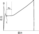
- FIG. 9 shows a stress strain curve of polyamide resin.
- FIG. 10 is a cross-sectional view showing a parison placed in a mold according to an embodiment of the present invention.
- FIG. 11 is a cross-sectional view showing a state in which the parison is stretched in the longitudinal axis direction x while heating the mold in the first stretching step according to an embodiment of the present invention.
- FIG. 12 is a cross section showing a state in which the parison stretched in the first stretching step is further stretched while being heated at a higher internal pressure than in the first stretching step in the second stretching step according to an embodiment of the present invention. represent a diagram
- FIG. 13 is a cross-sectional view showing the state after the second stretching step is completed.
- Balloon 20 can be manufactured by performing a second stretching process after the first stretching process.
- the parison is placed in a mold, and while the mold is heated, the parison is stretched longitudinally until it exceeds the necking region Rn of the stress strain curve of the resin constituting the balloon 20, for example, as shown in FIG. Stretch in the axial direction x.
- the parison that has been stretched beyond the necking region R n is further stretched while being heated while the internal pressure of the parison is higher than in the first stretching step.
- the molecular chains shift due to strain and exhibit a certain amount of stress, but when the strain exceeds a certain level, the molecular chains approach each other and become densely oriented, creating strong intermolecular forces between the molecular chains.
- the stress increases upwardly.
- the parison is first stretched in the longitudinal axis direction x until it exceeds the necking region Rn
- the parison stretched until it exceeds the necking region Rn is heated under a high internal pressure. Stretch it further.
- the average film thickness Tx at the thinnest position X of the central section 23C of the straight pipe portion 23 is 30 ⁇ m or less, and the amount of film thickness change in a predetermined section in the longitudinal axis direction x is 2.0 ⁇ 10 - 4 or less can be manufactured.
- the parison 30 is a cylindrical member having an inner cavity 31, and can be produced, for example, by extrusion molding.
- the parison 30 has one end and the other end, and extends in the longitudinal direction x from one end to the other end.
- the cross-sectional shape of the parison 30 in the direction perpendicular to the longitudinal axis direction x, that is, in the radial direction y, may be substantially the same in the longitudinal axis direction x.
- the cross-sectional shape of the parison 30 in the radial direction y may differ depending on the position in the longitudinal axis direction x.
- the material forming the parison 30 can refer to the material forming the balloon 20 described above.
- the inner wall surface forming the lumen 46 includes a straight pipe portion 43, a proximal tapered portion 42 located on the proximal side of the straight pipe portion 43, and a straight pipe portion 43.
- a mold 40 having a distal tapered portion 44 located distal to the tube portion 43 is prepared.
- the inner wall surface forming the inner cavity 46 of the mold 40 has a proximal sleeve portion 41 located more proximally than the proximal tapered portion 42 and a more distal side than the distal tapered portion 44 . It may have a distal sleeve portion 45 located therein.
- the mold 40 may be composed of one member or a plurality of members.
- the mold 40 may be composed of a plurality of half bodies, that is, a plurality of mold members may be connected so as to be divisible in the radial direction, or a plurality of mold members may be connected to each other so as to be divisible in the longitudinal direction. They may be connected so as to be divisible in the direction.
- the parison 30 is placed in the inner cavity 46 of the mold 40.
- the parison 30 has a part with a large outer diameter, that is, if the parison 30 has a bubble corresponding to the straight tube part 23, the proximal tapered part 22, and the distal tapered part 24 of the balloon 20,
- the parison 30 is preferably arranged so that the bubble is located in the straight pipe section 43 of the mold 40. This makes it easy to form the straight pipe portion 23, proximal tapered portion 22, and distal tapered portion 24 of the balloon 20 by stretching the portions.
- a first stretching step is performed in which the parison 30 is stretched in the longitudinal axis direction x while heating the mold 40. At this time, the parison 30 is stretched until it exceeds the necking region R n of the stress strain curve of the resin forming the parison 30 .
- the necking region Rn is a region exhibiting flat stress after the yield point B and the lower yield point L, and in this region, a phenomenon occurs in which the molecular chains of the resin that have started plastic deformation are shifted due to stress. ing.
- the parison 30 is stretched until it exceeds such necking region Rn .
- the internal pressure of the parison 30 in the first stretching step is preferably lower than the internal pressure of the parison 30 in the second stretching step. Thereby, in the first stretching step, the parison 30 can be stretched in the longitudinal axis direction x while being restrained from stretching in the circumferential direction z.
- the parison 30 is prepared by being stretched to some extent in the longitudinal axis direction x before the first stretching process, such as when the parison 30 is produced by extrusion molding, the parison 30 is stretched until it exceeds the necking region R n in the first stretching process.
- the amount of stretching in the longitudinal axis direction x varies depending on the degree of stretching in the preparation stage of the parison 30, such as during extrusion molding. That is, if the parison 30 has been stretched in the longitudinal axis direction x to some extent in the preparation stage, the amount by which the parison 30 is stretched in the longitudinal axis direction x in the first stretching step may be correspondingly small.
- a second stretching process is performed in which the parison 30 is further stretched in a state where the internal pressure of the parison 30 is higher than that in the first stretching process while heating the mold 40. Since the internal pressure of the parison 30 is higher in the second stretching step than in the first stretching step, the parison 30 is stretched in the longitudinal axis direction x while being restrained from stretching in the circumferential direction z in the first stretching step. In the second stretching step, the parison 30 is stretched in the radial direction y and also in the longitudinal axis direction x.
- the average film thickness Tx at the thinnest position The balloon 20 can have a variation of 2.0 ⁇ 10 ⁇ 4 or less.
- the stress-strain curve shown in Figure 9 clearly shows the necking region R n where the stress is constant, but depending on the resin, the region where the stress is constant may be short or the flat region may be unclear. be.
- the first point where the differential coefficient of the stress-strain curve becomes 5% or more of the average rate of change up to the yield point B is defined as the necking region R n .
- the first stretching step may be performed until the strain exceeds this strain.
- the heating temperature in the first stretching step and the second stretching step can be set to around the glass transition temperature of the resin forming the balloon 20.
- a heating means for the mold 40 a known heater or the like can be used as appropriate.
- a fluid is introduced into the inner cavity 31 of the parison 30 to pressurize the inside of the parison 30, and the pressure is preferably 3 MPa or less.
- the inner cavity 31 of the parison 30 and the outside of the parison 30 may have the same pressure, that is, the inner cavity 31 of the parison 30 may be in a state where no pressure is applied.
- a fluid is introduced into the inner cavity 31 of the parison 30 to pressurize the inside of the parison 30, and this pressure is applied to the inner cavity 31 of the parison 30 in the first stretching process.
- It is higher than the pressure, for example, preferably 1 MPa or more, more preferably 1.5 MPa or more, and even more preferably 2 MPa or more.
- it is preferably 5 MPa or less, more preferably 4.5 MPa or less, even more preferably 4 MPa or less, and may be 3 MPa or less.
- the parison 30 stretched in the longitudinal axis direction x to the state shown in FIG. 13 is further stretched in the radial direction y and the longitudinal direction It can be blow molded into a balloon shape.
- the parison 30 is not pressurized in the first stretching step, and that pressurization of the parison 30 is started after the necking region R n is exceeded in the second stretching step. This makes it easy to form the balloon 20 in which the amount of change in film thickness in a predetermined section in the longitudinal axis direction x is 2.0 ⁇ 10 ⁇ 4 or less.
- Example 1 A parison having a bubble length of 71 mm was prepared by extrusion molding a polyamide ether elastomer. The parison was placed in a mold with a length of 150 mm in the longitudinal direction of the straight pipe part, and while the mold was heated to 60° C., an internal pressure of 20 bar (2 MPa) was applied to the parison, and the parison was stretched at a speed of 10 mm/2 in the longitudinal direction. It was stretched at s. Next, while heating the mold to 60° C., the parison was blow-molded at a stretching speed of 140 mm/s while applying a pressure of 38 bar (3.8 MPa). Furthermore, a balloon was obtained by annealing at 130° C. for 50 seconds.
- the amount of change in film thickness shown in Table 1 is the value if the amount of change in film thickness is the same among the amount of change in the section from the thinnest position to a predetermined position on the proximal side or distal side; If they are different, the larger value is used.
- Example 2 Thirty more balloons were produced in the same manner as in Example 1. Internal pressure was continued to be applied to these 30 balloons until they were destroyed, and the state of the cracks after the destruction was observed. All 30 balloons were cracked in the longitudinal direction, but none of the balloons were cracked in the circumferential direction.
- Comparative example 1 A parison was prepared in the same manner as in Example 1. The parison was placed in the inner cavity of the same mold as in Example 1, and while the mold was heated to 60° C., an internal pressure of 32.5 bar (3.25 MPa) was applied to the parison and blow molding was performed at a stretching speed of 140 mm/s. Furthermore, a balloon was obtained by annealing at 130° C. for 50 seconds.
- the amount of change in film thickness shown in Table 1 is the value if the amount of change in film thickness is the same among the amount of change in the section from the thinnest position to a predetermined position on the proximal side or distal side; If they are different, the larger value is used.
- Example 1 and Comparative Example 1 both had a film thickness of about 25 ⁇ m at the thinnest position, the amount of film thickness change in a predetermined section in the longitudinal axis direction was that of Balloon No. 1 of Example 1.
- 1 ⁇ No. Balloon No. 5 of Comparative Example 1 was 1.62 ⁇ 10 ⁇ 4 to 1.83 ⁇ 10 ⁇ 4 . 6 ⁇ No. 9, it was as large as 2.09 ⁇ 10 ⁇ 4 to 2.43 ⁇ 10 ⁇ 4 .
- the balloon manufactured by the manufacturing method of Comparative Example 1 there was a part where the film thickness in the longitudinal axis direction suddenly changed, and it is thought that stress concentration in the circumferential direction occurred in this part, causing the cross-shaped crack. .
- the film thickness change in the longitudinal direction was gradual, stress concentration in the circumferential direction was suppressed, and it is thought that only longitudinal cracks occurred.
- Balloon catheter 3 Shaft 4: Hub 5: Guide wire insertion section 6: Fluid injection section 20: Balloon 21: Proximal sleeve section 22: Proximal tapered section 23: Straight tube section 23C: Central section 24: Distal tapered section 25: Distal sleeve portion 30: Parison 31: Parison lumen 40: Mold 41: Proximal sleeve portion 42 of the mold: Proximal tapered portion 43 of the mold: Straight pipe portion 44 of the mold: Distal tapered part 45 of the mold: Distal sleeve part 46 of the mold: Lumen a to h of the mold: 8 points X: Thinnest position P: Proximal position D: Distal position Tx: Average film thickness at the thinnest position Tp: Average film thickness at the proximal position Td: Average film thickness at the distal position L 0 : 0% position L 30 : 30% position L 70 : 70% position L 100 : 100% position B: Yield point L: Lower yield
Landscapes
- Health & Medical Sciences (AREA)
- Life Sciences & Earth Sciences (AREA)
- Heart & Thoracic Surgery (AREA)
- Engineering & Computer Science (AREA)
- Biophysics (AREA)
- Pulmonology (AREA)
- Child & Adolescent Psychology (AREA)
- Anesthesiology (AREA)
- Biomedical Technology (AREA)
- Hematology (AREA)
- Animal Behavior & Ethology (AREA)
- General Health & Medical Sciences (AREA)
- Public Health (AREA)
- Veterinary Medicine (AREA)
- Media Introduction/Drainage Providing Device (AREA)
Priority Applications (1)
| Application Number | Priority Date | Filing Date | Title |
|---|---|---|---|
| JP2024514837A JPWO2023199634A1 (https=) | 2022-04-15 | 2023-03-02 |
Applications Claiming Priority (2)
| Application Number | Priority Date | Filing Date | Title |
|---|---|---|---|
| JP2022-067321 | 2022-04-15 | ||
| JP2022067321 | 2022-04-15 |
Publications (1)
| Publication Number | Publication Date |
|---|---|
| WO2023199634A1 true WO2023199634A1 (ja) | 2023-10-19 |
Family
ID=88329294
Family Applications (1)
| Application Number | Title | Priority Date | Filing Date |
|---|---|---|---|
| PCT/JP2023/007705 Ceased WO2023199634A1 (ja) | 2022-04-15 | 2023-03-02 | バルーンカテーテル用バルーン |
Country Status (2)
| Country | Link |
|---|---|
| JP (1) | JPWO2023199634A1 (https=) |
| WO (1) | WO2023199634A1 (https=) |
Citations (3)
| Publication number | Priority date | Publication date | Assignee | Title |
|---|---|---|---|---|
| JPH0392173A (ja) * | 1989-08-25 | 1991-04-17 | C R Bard Inc | カテーテル |
| JP2000217924A (ja) * | 1999-02-01 | 2000-08-08 | Kanegafuchi Chem Ind Co Ltd | 拡張カテーテル用拡張体およびその製造方法 |
| JP2001314512A (ja) * | 2000-05-09 | 2001-11-13 | Kanegafuchi Chem Ind Co Ltd | 均一膜厚バルーンおよびバルーンカテーテル |
-
2023
- 2023-03-02 WO PCT/JP2023/007705 patent/WO2023199634A1/ja not_active Ceased
- 2023-03-02 JP JP2024514837A patent/JPWO2023199634A1/ja active Pending
Patent Citations (3)
| Publication number | Priority date | Publication date | Assignee | Title |
|---|---|---|---|---|
| JPH0392173A (ja) * | 1989-08-25 | 1991-04-17 | C R Bard Inc | カテーテル |
| JP2000217924A (ja) * | 1999-02-01 | 2000-08-08 | Kanegafuchi Chem Ind Co Ltd | 拡張カテーテル用拡張体およびその製造方法 |
| JP2001314512A (ja) * | 2000-05-09 | 2001-11-13 | Kanegafuchi Chem Ind Co Ltd | 均一膜厚バルーンおよびバルーンカテーテル |
Also Published As
| Publication number | Publication date |
|---|---|
| JPWO2023199634A1 (https=) | 2023-10-19 |
Similar Documents
| Publication | Publication Date | Title |
|---|---|---|
| KR100866340B1 (ko) | 의료용 벌룬 카테테르 | |
| CN100368034C (zh) | 气球导管 | |
| JP6706889B2 (ja) | バルーンカテーテル | |
| US8088121B2 (en) | Catheter | |
| JP4914281B2 (ja) | カテーテル | |
| JP5066992B2 (ja) | バルーンカテーテル | |
| US20240075258A1 (en) | Balloon for balloon catheter and method of manufacturing balloon catheter | |
| JP4815657B2 (ja) | 医療用ポリマーブレンド材料およびこの材料を用いた医療用バルーン | |
| WO2023199634A1 (ja) | バルーンカテーテル用バルーン | |
| JP4914282B2 (ja) | 押圧性を備えたカテーテル | |
| WO2024262529A1 (ja) | バルーンカテーテル、および該バルーンカテーテルにおけるバルーンの拡張方法 | |
| JP2004298354A (ja) | 拡張用バルーンおよびこれを備えたバルーンカテーテル | |
| JP4785567B2 (ja) | カテーテル | |
| JP2025002563A (ja) | バルーンカテーテル、および該バルーンカテーテルにおけるバルーンの拡張方法 | |
| WO2023176182A1 (ja) | バルーンカテーテル用バルーン | |
| JP4967258B2 (ja) | バルーンおよびバルーンカテーテル | |
| US20250269153A1 (en) | Balloon for balloon catheter, balloon catheter including same, and method for producing balloon catheter | |
| JP2025002564A (ja) | バルーンカテーテル | |
| US20250269155A1 (en) | Balloon for balloon catheter and balloon catheter including same | |
| JP2008264119A (ja) | 押圧性を備えたカテーテル | |
| US20260076709A1 (en) | Balloon for balloon catheter and balloon catheter including same | |
| US20250099722A1 (en) | Catheter balloon | |
| JP6184070B2 (ja) | バルーンカテーテル用バルーンの製造方法 | |
| JP2025002565A (ja) | バルーンカテーテル | |
| JP2024141505A (ja) | バルーンカテーテル |
Legal Events
| Date | Code | Title | Description |
|---|---|---|---|
| 121 | Ep: the epo has been informed by wipo that ep was designated in this application |
Ref document number: 23788056 Country of ref document: EP Kind code of ref document: A1 |
|
| ENP | Entry into the national phase |
Ref document number: 2024514837 Country of ref document: JP Kind code of ref document: A |
|
| NENP | Non-entry into the national phase |
Ref country code: DE |
|
| 122 | Ep: pct application non-entry in european phase |
Ref document number: 23788056 Country of ref document: EP Kind code of ref document: A1 |