WO2023199548A1 - インヒビタスイッチ - Google Patents
インヒビタスイッチ Download PDFInfo
- Publication number
- WO2023199548A1 WO2023199548A1 PCT/JP2022/045368 JP2022045368W WO2023199548A1 WO 2023199548 A1 WO2023199548 A1 WO 2023199548A1 JP 2022045368 W JP2022045368 W JP 2022045368W WO 2023199548 A1 WO2023199548 A1 WO 2023199548A1
- Authority
- WO
- WIPO (PCT)
- Prior art keywords
- movable member
- spool
- contact
- inhibitor switch
- movable
- Prior art date
- Legal status (The legal status is an assumption and is not a legal conclusion. Google has not performed a legal analysis and makes no representation as to the accuracy of the status listed.)
- Ceased
Links
Images






Classifications
-
- F—MECHANICAL ENGINEERING; LIGHTING; HEATING; WEAPONS; BLASTING
- F16—ENGINEERING ELEMENTS AND UNITS; GENERAL MEASURES FOR PRODUCING AND MAINTAINING EFFECTIVE FUNCTIONING OF MACHINES OR INSTALLATIONS; THERMAL INSULATION IN GENERAL
- F16H—GEARING
- F16H59/00—Control inputs to control units of change-speed- or reversing-gearings for conveying rotary motion
- F16H59/02—Selector apparatus
- F16H59/08—Range selector apparatus
- F16H59/10—Range selector apparatus comprising levers
- F16H59/105—Range selector apparatus comprising levers consisting of electrical switches or sensors
-
- F—MECHANICAL ENGINEERING; LIGHTING; HEATING; WEAPONS; BLASTING
- F16—ENGINEERING ELEMENTS AND UNITS; GENERAL MEASURES FOR PRODUCING AND MAINTAINING EFFECTIVE FUNCTIONING OF MACHINES OR INSTALLATIONS; THERMAL INSULATION IN GENERAL
- F16H—GEARING
- F16H61/00—Control functions within control units of change-speed- or reversing-gearings for conveying rotary motion ; Control of exclusively fluid gearing, friction gearing, gearings with endless flexible members or other particular types of gearing
- F16H61/02—Control functions within control units of change-speed- or reversing-gearings for conveying rotary motion ; Control of exclusively fluid gearing, friction gearing, gearings with endless flexible members or other particular types of gearing characterised by the signals used
- F16H61/0262—Control functions within control units of change-speed- or reversing-gearings for conveying rotary motion ; Control of exclusively fluid gearing, friction gearing, gearings with endless flexible members or other particular types of gearing characterised by the signals used the signals being hydraulic
- F16H61/0276—Elements specially adapted for hydraulic control units, e.g. valves
- F16H61/0286—Manual valves
Definitions
- the present invention relates to an inhibitor switch.
- Patent Document 1 discloses a range detection device for an automatic transmission.
- a movable member including a movable contact is connected to a spool of a manual valve.
- the movable member reciprocates with the spool in conjunction with rotation of the manual shaft.
- the movable member has a slider with a movable contact and a shaft portion that connects the slider and the spool.
- the shaft portion is connected to the spool in the radial direction of the forward and backward movement direction of the spool. Therefore, when the movable member moves in conjunction with the forward and backward movement of the spool, the movable member tends to tilt with respect to the forward and backward movement direction. If the movable member moves while being tilted, the movable contact may reciprocate while being locally strongly pressed against the fixed contact. This increases the sliding resistance when the movable member moves back and forth, leading to an increase in the amount of wear on the movable contact and the fixed contact.
- the inhibitor switch in an embodiment of the present invention is a movable member that moves relative to the fixed member in the first axial direction; a movable contact provided on a portion of the movable member facing the fixed member; A fixed contact provided on a portion of the fixed member facing the movable member, the inhibitor switch comprising:
- the movable member has a connecting portion with a shaft member that moves in the second axial direction according to the selection range, The connecting portion is connected to the shaft member from a radial direction of the second shaft, The connecting portion is provided with a regulating portion that restricts the inclination of the connecting portion with respect to the second axis.
- FIG. 1 is a schematic diagram showing a schematic configuration of a power transmission device.
- FIG. 2 is a diagram explaining the case.
- FIG. 3 is a diagram explaining the case.
- FIG. 4 is a perspective view illustrating the area around the inhibitor switch.
- FIG. 5 is a diagram illustrating the inhibitor switch.
- FIG. 6 is an enlarged view of the main parts of the inhibitor switch.
- FIG. 7 is a diagram illustrating the regulating section.
- FIG. 8 is an enlarged view of the main parts of the inhibitor switch.
- FIG. 9 is a diagram illustrating the operation of the inhibitor switch.
- FIG. 10 is a diagram illustrating the operation of the inhibitor switch.
- FIG. 11 is a diagram illustrating an inhibitor switch according to a comparative example.
- FIG. 12 is a diagram illustrating a regulating section according to modification 1.
- FIG. 13 is a diagram illustrating a regulating section according to modification 2.
- FIG. 14 is a diagram illustrating a regulating section according to modification 3.
- the power transmission device is a device having at least a power transmission mechanism, and the power transmission mechanism is, for example, at least one of a gear mechanism, a differential gear mechanism, and a speed reduction mechanism.
- the power transmission device 1 has a function of transmitting the output rotation of the engine, but the power transmission device 1 transmits the output rotation of at least one of the engine and the motor (rotating electric machine). It's fine as long as it's something you do.
- “Overlapping in a predetermined direction” means that a plurality of elements are lined up in a predetermined direction, and has the same meaning as "overlapping in a predetermined direction.”
- the "predetermined direction” is, for example, an axial direction, a radial direction, a gravity direction, a vehicle longitudinal direction, or the like. If a drawing shows multiple elements (parts, parts, etc.) lining up in a predetermined direction, there is a sentence in the description explaining that they overlap when viewed in the predetermined direction. It can be considered as.
- “Do not overlap when viewed in a predetermined direction” and “offset when viewed in a predetermined direction” mean that multiple elements are not lined up in a predetermined direction, and "do not overlap in a predetermined direction” , is synonymous with the expression “offset in a predetermined direction”.
- the "predetermined direction” is, for example, an axial direction, a radial direction, a gravity direction, a vehicle longitudinal direction (vehicle forward direction, vehicle backward direction), or the like. If a drawing shows that multiple elements (parts, parts, etc.) are not lined up in a predetermined direction, there is a sentence in the description explaining that they do not overlap when viewed in a predetermined direction. It can be considered as.
- the first element (component, section, etc.) is located between the second element (component, section, etc.) and the third element (component, section, etc.) when viewed from a predetermined direction" means In this case, the first element can be observed to be between the second and third elements.
- the "predetermined direction" includes an axial direction, a radial direction, a direction of gravity, a vehicle running direction (vehicle forward direction, vehicle backward direction), and the like.
- vehicle forward direction vehicle backward direction
- the first element is located between the second element and the third element when viewed in the radial direction. It can be said that it is located.
- Axial direction means the axial direction of the rotating shaft of the components that constitute the power transmission device.
- Ring direction means a direction perpendicular to the rotational axis of the components constituting the power transmission device.
- the parts are, for example, a motor, a gear mechanism, a differential gear mechanism, etc.
- FIG. 1 is a schematic diagram illustrating a schematic configuration of a power transmission device 1.
- the housing HS of the power transmission device 1 includes a case 10, a first cover 11, and a second cover 12.
- the first cover 11 and the second cover 12 are joined to one side and the other side of the case 10, respectively.
- a torque converter T/C, a forward/reverse switching mechanism 2, a variator 3, a deceleration mechanism 4, a differential device 5, a control valve 6, an inhibitor switch 7, a parking mechanism 8, etc. are housed inside the housing HS.
- the torque converter T/C, the forward/reverse switching mechanism 2, the variator 3, the speed reduction mechanism 4, and the differential gear 5 correspond to the power transmission mechanism of the power transmission device 1.
- the output rotation of the engine ENG (drive source) is input to the forward/reverse switching mechanism 2 via the torque converter T/C.
- the rotation input to the forward/reverse switching mechanism 2 is sequentially transmitted to the differential device 5 (differential gear mechanism) via the variator 3 and the speed reduction mechanism 4.
- the rotation of the differential gear 5 is transmitted to the drive wheels WH, WH via the left and right drive shafts DA, DB.
- the case 10 has a partition wall 102 that partitions the internal space of the case 10.
- the partition wall portion 102 is provided in the space within the case 10 in a direction that crosses the rotation axis X1 direction, which is a direction along the output rotation of the engine ENG (drive source).
- the partition wall portion 102 partitions the space inside the case 10 into two spaces in the direction of the rotation axis X1.
- One side of the partition wall 102 in the direction of the rotation axis X1 is the first chamber S1, and the other side is the third chamber S3.
- the opening on the side of the first chamber S1 is sealed with the second cover 12 (torque converter cover) to form a closed first chamber S1.
- the opening on the third chamber S3 side is sealed with the first cover 11 (side cover) to form a closed third chamber S3.
- the forward/reverse switching mechanism 2, the speed reduction mechanism 4, and the differential gear 5 are housed in the first chamber S1.
- the variator 3 is accommodated in the third chamber S3.
- a housing portion 14 is attached to the side surface on the front side of the vehicle.
- the housing portion 14 is provided with an opening facing toward the front side of the vehicle.
- the opening of the accommodating portion 14 is sealed with the third cover 13 to form a closed second chamber S2.
- the control valve 6 is housed in the second chamber S2.
- the selection range of the power transmission device 1 is set according to the driver's shift operation and button operation.
- the power transmission device 1 includes an inhibitor switch 7 for detecting a set selection range.
- driving range “reverse range”, “parking range”, etc. are examples of selected ranges.
- the inhibitor switch 7 outputs a signal indicating the detected selection range to a control device (not shown).
- a control device (not shown) controls the switching valve in the control valve 6 based on the selected range, and controls the oil supplied to the power transmission mechanism from the hydraulic control circuit in the control valve 6.
- the inhibitor switch 7 is arranged in the second chamber S2 described above.
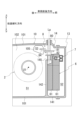
- FIG. 2 is a schematic diagram showing the case 10 viewed from the second cover 12 side.
- FIG. 2 is a schematic cross-sectional view taken along line AA in FIG.
- FIG. 3 is a diagram of the housing section 14 viewed from the front side of the vehicle.
- the first cover 11 and the second cover 12 are schematically shown with imaginary lines.
- the appearance of the control valve 6 and the inhibitor switch 7 housed in the housing portion 14 is schematically shown.
- the peripheral wall portion 141 and the wall portion 142 of the accommodating portion 14 are shown with crossed hatching.
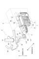
- FIG. 4 is a perspective view of the parking mechanism 8, control valve 6, and inhibitor switch 7 viewed from the third cover 13 side.
- the control valve 6 is schematically shown with a virtual line.
- the inhibitor switch 7 is arranged within the second chamber S2.
- the inhibitor switch 7 converts the rotation of the manual shaft 80 of the parking mechanism 8 into forward and backward movement of a movable member 72, which will be described later, and is used to specify the selection range of the power transmission device 1.
- the first chamber S1 and the second chamber S2 are separated by a wall 142 on the case 10 side.
- a through hole 145 is provided on the upper side of the wall portion 142 .
- the first chamber S1 and the second chamber S2 communicate with each other.
- a through hole 105 is provided on the upper side of the case 10. In the area where the through hole 105 is provided, the first chamber S1 and the third chamber S3 communicate with each other.
- the parking mechanism 8 includes a manual shaft 80, a detent plate 81, a manual plate 82, and a park rod 84. These components of the parking mechanism 8 are arranged across the first chamber S1, the second chamber S2, and the third chamber S3.
- the rotation axis Lp of the manual shaft 80 is oriented along the vertical line VL direction.
- the upper end of the manual shaft 80 passes through the peripheral wall 101 and is located outside the case 10 .
- the rotational driving force of an actuator (not shown) is input to the upper end side of the manual shaft 80.
- the manual shaft 80 rotates around the rotation axis Lp by the rotational driving force of the actuator.
- the actuator is driven according to a selection range of a select lever (not shown) to arrange the manual shaft 80 at an angular position around the rotation axis Lp.
- the angular position around the rotation axis Lp is predetermined according to the selection range.
- the manual shaft 80 may be designed to rotate around the rotation axis Lp by an operating force transmitted via a wire extending from the select lever.
- the detent plate 81 is fitted onto the manual shaft 80 so that it cannot rotate relative to the manual shaft 80.
- a park rod 84 is connected to the detent plate 81.
- the distal end side of the park rod 84 passes through the through hole 105 and is disposed in the third chamber S3.
- the park rod 84 operates to engage and disengage a park pole (not shown) and a park gear (not shown) in cooperation with a support actuator (not shown).
- a manual plate 82 is provided below the detent plate 81 in the direction of the vertical line VL.
- the manual plate 82 is connected to the detent plate 81 via a connecting portion 83 (see FIG. 3).
- the connecting portion 83 has a cylindrical shape surrounding the manual shaft 80. The detent plate 81, the manual plate 82, and the connecting portion 83 rotate together with the manual shaft 80.
- the manual plate 82 is provided with a plate-shaped arm portion 85.
- the arm portion 85 is formed integrally with the manual plate 82.
- the arm portion 85 extends from the manual plate 82 in the radial direction of the rotation axis Lp.
- a disk-shaped connection piece 86 is provided at the tip of the arm portion 85 .
- the arm portion 85 is bent in a direction along the rotation axis Lp at a position away from the manual plate 82.
- the arm portion 85 extends downward along the rotation axis Lp, and then the distal end side of the arm portion 85 is further bent in the radial direction of the rotation axis Lp.
- connection piece 86 is provided with a position shifted from the manual plate 82 in the direction of the rotation axis Lp, and is arranged substantially parallel to the manual plate 82.
- the connecting piece 86 is connected to a spool 66 of a manual valve 65, which will be described later.
- control valve 6 is housed in the second chamber S2.
- the control valve 6 has a basic configuration in which a separate plate (not shown) is sandwiched between valve bodies 61, 61.
- the control valve 6 is fixed to the wall portion 142 with bolts (not shown).
- the control valve 6 is vertically arranged with the stacking direction of the valve bodies 61, 61 aligned with the longitudinal direction of the vehicle.
- a manual valve 65 is provided inside the control valve 6 to switch the hydraulic pressure supply destination according to the selected range.
- the manual valve 65 has a spool 66 (shaft member) and a spool hole 67.
- the spool hole 67 has a plurality of ports open therein corresponding to shift ranges.
- the control valve 6 has a substantially L-shape in which a notch 610 is provided in a substantially rectangular valve body 61 when viewed from the front side of the vehicle.
- the notch 610 is provided on the upper second cover 12 side in the direction of the vertical line VL when viewed from the front side of the vehicle.
- the through hole 145 on the case 10 side is located in the notch 610 when viewed from the front side of the vehicle.
- an inhibitor switch 7 is provided in the second chamber S2.
- the inhibitor switch 7 is fixed to the side surface of the control valve 6 on the vehicle front side with a bolt (not shown).
- the inhibitor switch 7 is disposed at a position where a portion of the inhibitor switch 7 overlaps the through hole 145 when viewed from the front side of the vehicle.
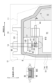
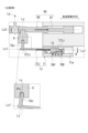
- FIG. 5 is a diagram illustrating the inhibitor switch 7.
- FIG. 5 is a schematic cross-sectional view taken along the line AA in FIG. 3.
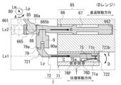
- FIG. 6 is an enlarged view of the main parts of the inhibitor switch 7.
- FIG. 6 is an enlarged view of area A in FIG.
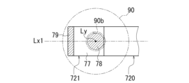
- FIG. 7 is a diagram illustrating the regulating portion 79 of the inhibitor switch 7.
- FIG. 7 is a schematic cross-sectional view taken along the line AA in FIG.
- FIG. 8 is an enlarged view of the main parts of the inhibitor switch 7.
- FIG. 8 is an enlarged view of region B in FIG. Note that FIGS. 5 to 8 show the case where the P range is selected.
- the connecting piece 86 of the arm portion 85 described above has a circular outer shape when viewed from the vertical line VL direction. As shown in FIG. 6, the width W2 of the connecting piece 86 is larger than the width W1 of the arm portion 85 (W2>W1).
- one end 661 side of the spool 66 of the manual valve 65 is connected to the connection piece 86.
- the axis Lx2 of the spool 66 is provided along the vehicle width direction.
- the other end 662 side of the spool 66 in the axis Lx2 direction is inserted into the spool hole 67.
- a groove 665 is provided on one end 661 side of the spool 66.
- the groove 665 crosses the spool 66 in the radial direction of the axis Lx2.
- a groove 665 is provided with an opening facing upward, and a connecting piece 86 is inserted into the groove 665 from the rear side of the vehicle.
- the groove 665 has side surfaces 665a and 665b that are parallel to each other.
- the side surfaces 665a and 665b are flat surfaces perpendicular to the axis Lx2.
- Side surfaces 665a and 665b of the groove 665 are provided on one side and the other side with the connecting piece 86 interposed therebetween.
- the interval between the side surfaces 665a and 665b of the groove 665 in the direction of the axis Lx2 is set to be slightly wider than the width W2 of the connecting piece 86.
- the depth L2 of the groove 665 is set deeper than the thickness L1 of the connecting piece 86 in the direction of the vertical line VL (L2>L1). Note that in the enlarged area of FIG. 3, a cross section around the connection piece 86 is schematically shown. When viewed from the vertical line VL direction, the connecting piece 86 is rotatable within the groove 665 (see FIG. 6).
- the manual shaft 80 rotates around the rotation axis Lp.
- the manual plate 82 which is connected to the manual shaft 80 in a relatively non-rotatable manner, also rotates around the rotation axis Lp.
- the arm portion 85 extending from the manual plate 82 and the connecting piece 86 at the tip of the arm portion 85 are displaced in the circumferential direction around the rotation axis Lp.
- the connecting piece 86 moves in the circumferential direction around the rotation axis Lp, as shown in FIG. Displace it to.
- the connecting piece 86 and the groove 665 constitute a link mechanism that converts rotational movement of the manual shaft 80 into linear movement of the spool 66.
- a connecting member 9 is connected to the spool 66.
- the connecting member 9 is connected at a position adjacent to the groove 665.
- the connecting member 9 is adjacent to the groove 665 on the other end 662 side in the direction of the axis Lx2.
- the connecting member 9 is a cylindrical member.
- the connecting member 9 is provided in a direction along the straight line Ly.
- the straight line Ly is a straight line along the radial direction of the axis Lx2.
- the connecting member 9 has a large diameter portion 90 and a small diameter portion 91.
- the large diameter portion 90 and the small diameter portion 91 are lined up in the direction of the straight line Ly.
- the large diameter portion 90 and the small diameter portion 91 are integrally provided in a concentric positional relationship.
- the small diameter portion 91 is press-fitted into the hole 663 of the spool 66 from the radial direction of the axis Lx2 (vehicle front side). Thereby, the connecting member 9 is connected to the spool 66 in a relatively non-rotatable manner.
- the end surface 90a of the large diameter portion 90 is a flat surface perpendicular to the straight line Ly.
- a hole 90b is opened in the end surface 90a.
- the hole 90b is formed along the straight line Ly and has a depth H1.
- the diameter of the hole 90b is set to D1.
- the inhibitor switch 7 is provided on the opposite side of the spool 66 across the connecting member 9 in the direction of the straight line Ly.
- the inhibitor switch 7 includes a movable member 72 connected to the connecting member 9 and a fixed member 71.
- the movable member 72 includes a beam portion 720, a connecting portion 721, and a contact support portion 722.
- the movable member 72 is arranged in parallel to the spool 66 on the front side of the vehicle when viewed from the spool 66.
- the movable member 72 is provided along the axis Lx1 (first axis).
- the axis Lx1 is a straight line parallel to the axis Lx2 of the spool 66.
- the beam portion 720 is a plate-like member having a predetermined width.
- a connecting portion 721 is integrally formed at one end of the beam portion 720 in the longitudinal direction.
- a contact support portion 722 is integrally formed at the other end of the beam portion 720 in the longitudinal direction.
- the straight line Ly is also a straight line along the radial direction of the axis Lx1.
- the connecting portion 721 has a base portion 77 provided at one end of the beam portion 720 .
- the base portion 77 is provided on the surface of the beam portion 720 on the spool 66 side.
- the base portion 77 extends in a direction (oblique direction) away from the contact support portion 722 as the base portion 77 moves away from the contact support portion 722 in the radial direction of the straight line Lx1.
- the base 77 is provided in a range that crosses the straight line Ly passing through the hole 90b of the connecting member 9 in the direction of the axis Lx1. ing.
- the distal end surface 77a of the base portion 77 is a flat surface perpendicular to the straight line Ly.
- the tip surface 77a is a flat surface that is also substantially parallel to the side surface 720a of the beam portion 720.
- An insertion portion 78 and a restriction portion 79 are provided on the distal end surface 77a.
- the restriction portion 79 is provided on the opposite side to the contact support portion 722 in the axis Lx1 direction. As shown in FIG. 6, the regulating portion 79 protrudes toward the spool 66 from the distal end surface 77a along the straight line Ly.
- the insertion portion 78 is a cylindrical projection centered on the straight line Ly.
- the diameter of the insertion portion 78 is set to D2.
- the diameter D2 of the insertion portion 78 is slightly smaller than the hole diameter D1 of the hole 90b on the side of the connecting member 9 (D2 ⁇ D1).
- the insertion portion 78 has a protrusion height set to H2 from the distal end surface 77a.
- the protrusion height H2 of the insertion portion 78 is set shorter than the depth H1 of the hole portion 90b (H2 ⁇ H1).
- the movable member 72 is connected to the connecting member 9 by inserting the insertion portion 78 into the hole 90b from the radial direction of the axis Lx2 of the spool 66 (direction of the straight line Ly).
- the insertion portion 78 is loosely fitted into the hole 90b of the connecting member 9, and relative rotation of the movable member 72 and the connecting member 9 about the straight line Ly is permitted.
- the movable member 72 is allowed to have a slight inclination with respect to the straight line Ly.
- the regulating portion 79 is provided at a position away from the insertion portion 78 in the radial direction of the straight line Ly.
- the regulating portion 79 is located on the opposite side (left side in the figure) from the contact support portion 722 when viewed from the insertion portion 78.
- the restriction portion 79 protrudes in the same direction as the insertion portion 78.
- the protruding height of the restricting portion 79 is smaller than the protruding height H2 of the insertion portion 78.
- the distal end surface 79a of the regulating portion 79 is a flat surface perpendicular to the straight line Ly.
- the restriction portion 79 is a continuous wall provided over the entire length of the base portion 77 in the direction orthogonal to the axis Lx1.
- the restricting portion 79 is provided in a range that crosses the insertion portion 78 in a direction orthogonal to the axis Lx1.
- the movable member 72 can swing about the insertion portion 78 as a fulcrum. Specifically, the movable member 72 can be slightly inclined with respect to a straight line Ly along the direction in which the movable member 72 and the connecting member 9 are connected. Therefore, the other end side of the movable member 72 where the contact support portion 722 is provided can tilt in the direction away from the spool 66 (vertical direction in FIG. 5: arrow direction).
- the restricting portion 79 is provided on the opposite side of the contact support portion 722 when viewed from the insertion portion 78 . Therefore, when the contact support part 722 side tries to displace in the direction away from the spool 66, when the distal end surface 79a of the regulating part 79 comes into contact with the end surface 90a of the connecting member 9, the contact support part 722 side moves away from the spool 66. displacement can be regulated.
- the insertion portion 78 is inserted into the hole 90b on the side of the connecting member 9, the distal end surface 79a of the regulating portion 79 is in contact with the end surface 90a of the connecting member 9, and the insertion portion 78 is Insertion into the hole 90b is restricted.
- the regulating portion 79 be provided at a position where the distance L79 from the straight line Ly is longer. This is because the reaction force in the direction that resists the inclination of the movable member 72 can be increased.
- the fixing member 71 of the inhibitor switch 7 is a housing fixed to the control valve 6.
- the internal space 710 of the fixing member 71 is open toward the connecting member 9 in the direction of the axis Lx1.
- the fixing member 71 when viewed from the vertical line VL direction, has inner peripheral surfaces 71a and 71b that are parallel to each other with the axis Lx1 in between.
- a region of the movable member 72 on the contact support portion 722 side is inserted between the inner peripheral surfaces 71a and 71b.
- a contact piece 75 is provided in the contact support portion 722 on a surface facing the inner circumferential surface 71a.
- the inner peripheral surface 71a is located on the opposite side of the spool 66 when viewed from the contact piece 75.
- a fixed contact 76 is exposed on the inner peripheral surface 71a at a portion facing the contact support portion 722 (a portion facing the inner peripheral surface 71b). That is, the fixed contact 76 is provided on the opposite side of the spool 66 when viewed from the contact piece 75.
- the fixed contact 76 has fixed contacts 76P, 76R, 76N, and 76D corresponding to each shift range (P range, R range, N range, and D range), respectively.
- P range corresponds to "parking range”.
- R range corresponds to the "reverse range”.
- N range corresponds to the "neutral range”.
- D range corresponds to the "driving range”.
- the fixed contacts 76P, 76R, 76N, and 76D are arranged in this order from one side toward the other side in the axis Lx1 direction. Protrusions T, T, and T are provided between the fixed contacts 76P, 76R, 76N, and 76D in the axis Lx1 direction.
- the contact support portion 722 of the movable member 72 includes a contact piece 75 that is a movable contact, and a support portion 723 that supports the contact piece 75.
- the contact piece 75 is a strip-shaped copper plate. A plurality of contact pieces 75 are lined up in the width direction of the support portion 723. The contact piece 75 is provided in a direction along the axis Lx1. The other end 75b of the contact piece 75 is fixed to the support portion 723. One end 75a of the contact piece 75 is a free end. The contact piece 75 is inclined away from the support portion 723 as it goes from the other end 75b to the one end 75a. One end 75a of the contact piece 75 contacts the fixed contact 76 of the fixed member 71.
- the support portion 723 has locking pieces 723a and 723b on one side and the other side, respectively, across the axis Lx1.
- the locking piece 723a faces the inner peripheral surface 71a of the fixing member 71 with a gap therebetween.
- the locking piece 723b comes into contact with the inner circumferential surface 71b of the fixing member 71.
- the locking piece 723a faces the inner circumferential surface 71a of the fixed member 71 with a gap therebetween, so that the contact between the one end 75a of the contact piece 75 and the fixed contact 76 is not obstructed.
- the locking piece 723b comes into contact with the inner circumferential surface 71b of the fixed member 71, thereby restricting one end 75a of the contact piece 75 from separating from the fixed contact 76 (in the direction of the bold arrow in the figure).
- FIG. 9 and 10 are diagrams illustrating the operation of the inhibitor switch 7.
- FIG. 9 shows a case where the P range is selected.
- FIG. 10 shows a case where the D range is selected.
- the manual shaft 80 rotates around the rotation axis Lp.
- the manual plate 82 (see FIG. 5), which is connected to the manual shaft 80 in a relatively non-rotatable manner, also rotates around the rotation axis Lp.
- the arm portion 85 extending from the manual plate 82 and the connecting piece 86 at the tip of the arm portion 85 are displaced in the circumferential direction around the rotation axis Lp, thereby displacing the spool 66 in the direction of the axis Lx1.
- the inhibitor switch 7 When the selected range of the power transmission device 1 is the "P range", as shown in FIG. 66 at a position perpendicular to the axis Lx2. In this state, in the inhibitor switch 7, one end 75a of the contact piece 75 of the movable member 72 is arranged at a position where it comes into contact with the fixed contact 76P of the fixed member 71. Therefore, the inhibitor switch 7 outputs a signal corresponding to the P range.
- the manual shaft 80 rotates around the rotation axis Lp. (in the direction of arrow A in the figure).
- the connecting piece 86 is displaced in the circumferential direction around the rotation axis Lp in conjunction with the rotation of the manual shaft 80.
- the displacement of the connecting piece 86 causes the spool 66 to be displaced in the direction of pushing the spool 66 into the spool hole 67 (in the direction of arrow B in the figure).
- the spool 66 moves forward and backward in the axis Lx2 direction in conjunction with the rotation of the manual shaft 80.
- the movable member 72 connected to the spool 66 via the connecting member 9 is also displaced to the right in the figure (in the direction of arrow C in the figure).
- the movable member 72 moves in the direction of the axis Lx1.
- one end 75a of the contact piece 75 slides on the inner peripheral surface 71a (fixed contact 76) of the fixed member 71.
- One end 75a of the contact piece 75 moves the protrusions T, T, T in order.
- the inhibitor switch 7 outputs a signal corresponding to the D range.
- the insertion portion 78 provided in the connecting portion 721 is loosely fitted into the hole portion 90b of the connecting member 9.
- the insertion portion 78 constitutes a loose fitting portion that loosely fits into the spool 66 via the connecting member 9.
- the movable member 72 tends to wobble with respect to the spool 66 and the connecting member 9.
- the movable member 72 may tilt away from the spool 66 as it moves from the connecting portion 721 toward the contact support portion 722.
- one end 75a of the contact piece 75 is strongly pressed against the inner circumferential surface 71a, so that sliding resistance during reciprocating movement increases.
- a restricting portion 79 is provided between the movable member 72 and the connecting member 9 in order to reduce rattling.
- the regulating portion 79 is provided on the opposite side of the contact support portion 722 (contact piece 75) in the axis Lx1 direction when viewed from the insertion portion 78 (see FIG. 5).
- the locking piece 723b of the contact support portion 722 is brought into contact with the inner circumferential surface 71b of the fixing member 71.
- the movable member 72 is tilted toward the spool 66, and one end 75a of the contact piece 75 is prevented from moving away from the fixed contact 76 (in the direction of arrow E in the figure). .
- FIG. 11 is a diagram illustrating an inhibitor switch 7J according to a comparative example.
- the insertion portion 78J is provided in the connecting portion 721J.
- the insertion portion 78J is only loosely fitted into the hole 90b of the connecting member 9.
- the insertion portion 78J may be arranged in the hole portion 90b in a direction along the straight line Ly' that is inclined with respect to the straight line Ly (see the enlarged area in FIG. 11). Then, the movable member 72J tilts away from the spool 66 as it moves toward the contact support portion 722J (in the direction of arrow D in the figure). The movable member 72J may reciprocate in a direction along an axis Lx1' that is inclined with respect to the axis Lx2 of the spool 66. In this case, one end 75a of the contact piece 75 slides while being strongly pressed against the inner circumferential surface 71a.
- a regulating portion 79 is provided between the movable member 72 and the connecting member 9.
- the restricting portion 79 is provided on the opposite side of the contact piece 75 in the direction of the axis Lx1 when viewed from the insertion portion 78.
- the distal end surface 79a of the regulating portion 79 is in contact with the end surface 90a of the connecting member 9. This prevents the movable member 72 from tilting away from the spool 66 as it moves from the connecting portion 721 toward the contact support portion 722 . This reduces sliding resistance when the movable member 72 moves back and forth, and reduces wear between the one end 75a of the contact piece 75 and the fixed contact 76.
- the inhibitor switch 7 includes a movable member 72 that moves relative to the fixed member 71 in the axis Lx1 direction (first axis direction); A contact piece 75 (movable contact) provided on a portion of the movable member 72 facing the fixed member 71; A fixed contact 76 is provided at a portion of the fixed member 71 facing the movable member 72.
- the connecting portion 721 of the movable member 72 is connected to the spool 66 of the manual valve 65 via the connecting member 9.
- the spool 66 is a shaft member that moves in the axis Lx2 direction (second axis direction) according to the selection range.
- the connecting portion 721 of the movable member 72 is connected to the connecting member 9 from the direction of the straight line Ly along the radial direction of the axis Lx1.
- the connecting portion 721 of the movable member 72 is provided with a regulating portion 79 that regulates the inclination of the movable member 72 with respect to the spool 66 .
- the movable member 72 and the spool 66 are arranged in parallel along axes Lx1 and Lx2 that are parallel to each other. In conjunction with the forward and backward movement of the spool 66 along the axis Lx2 direction, the movable member 72 reciprocates along the axis Lx1 direction.
- the fixed contact 76 is provided on the opposite side of the spool 66 when viewed from the contact piece 75.
- the connecting portion 721 of the movable member 72 has an insertion portion 78 (loosely fitting portion) that loosely fits into the spool 66 via the connecting member 9.
- the regulating portion 79 is provided on the opposite side of the contact piece 75 in the direction of the axis Lx1 when viewed from the insertion portion 78.
- the movable member 72 is prevented from tilting in the direction of strongly pressing at least the contact piece 75 against the fixed contact 76.
- the restricting portion 79 is a protrusion that projects from the connecting portion 721 of the movable member 72 toward the connecting member 9 side in the straight line Ly direction.
- a protrusion corresponding to the restricting portion 79 may be provided on the connecting member 9 side.
- the connecting member 9 is press-fitted into the spool 66. Therefore, when press-fitting the connecting member 9, the position of the protrusion must be determined before press-fitting, making installation difficult. Therefore, by configuring as described above and making the restricting portion 79 a protrusion provided on the movable member 72 side, the connecting member 9 only needs to be press-fitted into the spool 66 in any direction, and assembly is simple. .
- FIG. 12 is a diagram illustrating modification example 1.
- FIG. 13 is a diagram illustrating modification example 2.
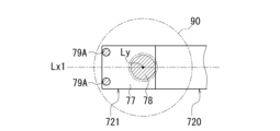
- the restricting portion 79 is a continuous wall provided over the entire length of the base portion 77 in the direction orthogonal to the axis Lx1 has been exemplified, but the present invention is not limited to this aspect.
- the restriction portions may be restriction portions 79A, 79A that are configured of dot-like protrusions provided on one side and the other side of the axis Lx1, respectively.
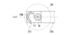
- the restricting portion may be a restricting portion 79B formed of an arc-shaped wall provided so as to surround the insertion portion 78.
- FIG. 14 is a diagram illustrating modification example 3.
- the fixed contact 76 is provided on the opposite side of the spool 66 when viewed from the contact piece 75 (see FIG. 5), but the present invention is not limited to this embodiment.
- the fixed contact 76 may be provided on the spool 66 side when viewed from the contact piece 75.
- the movable member 72 is inclined toward the spool 66 as it goes from the connecting portion 721 toward the contact support portion 722 .
- the restricting portion 79C is provided on the beam portion 720 side (on the right side in the figure) in the axis Lx1 direction when viewed from the insertion portion 78. Thereby, it is possible to prevent the contact piece 75 from sliding while being strongly pressed against the fixed contact 76.
- the restricting portion 79C may be configured with a point-like projection (see FIG. 12) or may be configured with an arc-shaped wall surrounding the insertion portion 78 (see FIG. 13).
- the restricting portion 79 is a protrusion protruding from the base 77, but the present invention is not limited to this embodiment.
- the protrusion projecting from the base 77 may not be provided.
- the tip end surface 77a (see FIG. 6) of the base 77 abuts against the connecting member 9 in the direction of the straight line Ly, thereby regulating the inclination of the movable member 72. That is, the base portion 77 of the movable member 72 functions as a restriction portion.
- connection member 9 was illustrated as being separate from the spool 66, but the connection member 9 is not limited to this aspect.
- the connecting member 9 may be formed integrally with the spool 66.
- the inhibitor switch 7 is fixed to the side surface of the control valve 6 as an example, the present invention is not limited to this embodiment.
- the inhibitor switch 7 may be fixed to the inner peripheral surface of the third cover 13 on the front side of the vehicle.
- the inhibitor switch 7 according to a certain aspect of the present invention is mounted on a vehicle, but the present invention is not limited to this aspect.
- the present invention can be applied to things other than vehicles. Further, in the case where a plurality of examples and modifications are described in this embodiment, these may be arbitrarily combined.
Landscapes
- Engineering & Computer Science (AREA)
- General Engineering & Computer Science (AREA)
- Mechanical Engineering (AREA)
- Control Of Transmission Device (AREA)
Abstract
Description
第1軸方向で、固定部材に対して相対移動する可動部材と、
前記可動部材の前記固定部材との対向部に設けられた可動接点と、
前記固定部材の前記可動部材との対向部に設けられた固定接点と、を有するインヒビタスイッチであって、
前記可動部材は、選択レンジに応じて第2軸方向に移動する軸部材との連結部を有しており、
前記連結部は、前記第2軸の径方向から前記軸部材に連結されており、
前記連結部には、当該連結部の前記第2軸に対する傾きを規制する規制部が設けられている。
動力伝達装置は、少なくとも動力伝達機構を有する装置であり、動力伝達機構は、例えば、歯車機構と差動歯車機構と減速機構の少なくともひとつである。
以下の実施形態では、動力伝達装置1がエンジンの出力回転を伝達する機能を有する場合を例示するが、動力伝達装置1は、エンジンとモータ(回転電機)のうちの少なくとも一方の出力回転を伝達するものであれば良い。
図面上において複数の要素(部品、部分等)が所定方向に並んでいることが図示されている場合は、明細書の説明において、所定方向視においてオーバーラップしていることを説明した文章があるとみなして良い。
図面上において複数の要素(部品、部分等)が所定方向に並んでいないことが図示されている場合は、明細書の説明において、所定方向視においてオーバーラップしていないことを説明した文章があるとみなして良い。
例えば、第2要素と第1要素と第3要素とが、この順で軸方向に沿って並んでいる場合は、径方向視において、第1要素は第2要素と第3要素との間に位置しているといえる。図面上において、所定方向視において第1要素が第2要素と第3要素との間にあることが図示されている場合は、明細書の説明において所定方向視において第1要素が第2要素と第3要素との間にあることを説明した文章があるとみなして良い。
「軸方向」とは、動力伝達装置を構成する部品の回転軸の軸方向を意味する。「径方向」とは、動力伝達装置を構成する部品の回転軸に直交する方向を意味する。部品は、例えば、モータ、歯車機構、差動歯車機構等である。
図1は、動力伝達装置1の概略構成を説明する模式図である。
図1に示すように、動力伝達装置1のハウジングHSは、ケース10と、第1カバー11と、第2カバー12と、とから構成される。第1カバー11と第2カバー12は、ケース10の一方側と他方側にそれぞれ接合されている。
前後進切替機構2に入力された回転は、バリエータ3、減速機構4を介して差動装置5(差動歯車機構)に順番に伝達される。差動装置5の回転は、左右の駆動軸DA、DBを介して駆動輪WH、WHに伝達される。
第1室S1には、前後進切替機構2と減速機構4と差動装置5と、が収容される。第3室S3には、バリエータ3が収容される。
第2室S2には、コントロールバルブ6が収容されている。
図3は、収容部14を車両前方側から見た図である。図3では、第1カバー11、第2カバー12を仮想線で模式的に示している。また、収容部14に収容されたコントロールバルブ6およびインヒビタスイッチ7の外観を模式的に示している。また、収容部14の周壁部141および壁部142に交差したハッチングを付して示している。
図4は、パーキング機構8、コントロールバルブ6およびインヒビタスイッチ7を第3カバー13側から見た斜視図である。図4では、コントロールバルブ6を仮想線で模式的に示している。
これらのパーキング機構8の構成要素は、第1室S1と、第2室S2と、第3室S3とに跨がって配置される。
マニュアルシャフト80の上端は、周壁部101を貫通して、ケース10の外部に位置している。マニュアルシャフト80の上端側には、図示しないアクチュエータの回転駆動力が入力される。マニュアルシャフト80は、アクチュエータの回転駆動力により回動軸Lp回りに回動する。なお、アクチュエータは、セレクトレバー(図示せず)の選択レンジに応じて駆動して、マニュアルシャフト80を、回動軸Lp回りの角度位置に配置する。回動軸Lp回りの角度位置は、選択レンジに応じてあらかじめ決められている。
なお、マニュアルシャフト80は、セレクトレバーから延びるワイヤを介して伝達される操作力により、回動軸Lp回りに回動する仕様であっても良い。
マニュアルバルブ65は、スプール66(軸部材)と、スプール孔67と、を有する。図示は省略するが、スプール孔67には、シフトレンジに対応した複数のポートが開口している。スプール66がスプール孔67内を軸線Lx2方向(第2軸方向)に進退移動することで、ポート間の連通が切り替わり、油圧の供給先が切り替えられる。
図6は、インヒビタスイッチ7の要部拡大図である。図6は、図5のA領域の拡大図である。
図7は、インヒビタスイッチ7の規制部79を説明する図である。図7は、図6のA-A断面の模式図である。
図8は、インヒビタスイッチ7の要部拡大図である。図8は、図5のB領域の拡大図である。なお、図5~図8は、Pレンジが選択されている場合を示している。
これにより、マニュアルプレート82から延びる腕部85と、腕部85の先端の接続片86が、回動軸Lp回りの周方向に変位する。
インヒビタスイッチ7は、連結部材9に接続された可動部材72と、固定部材71と、を有する。
可動部材72は、軸線Lx1(第1軸)に沿う向きに設けられている。軸線Lx1は、スプール66の軸線Lx2に平行な直線である。
連結部721は、梁部720の一端に設けられた基部77を有する。基部77は、梁部720のスプール66側の面に設けられている。図5に示すように、断面視において基部77は、直線Lx1の径方向に離れるにつれて、接点支持部722から離れる方向(斜め方向)に延びている。
基部77の先端面77aは、直線Lyに直交する平坦面である。先端面77aは、梁部720の側面720aとも略平行な平坦面である。先端面77aには、挿入部78と規制部79が設けられている。
図6に示すように、規制部79は、先端面77aから直線Lyに沿って、スプール66側に突出している。挿入部78は、直線Lyを中心とする円柱状の突起である。
挿入部78は、連結部材9の穴部90bに遊嵌しており、可動部材72と連結部材9との直線Ly回りの相対回転が許容されている。そして、可動部材72は、直線Lyに対する僅かな傾きが許容されている。
可動部材72の長手方向に沿う軸線Lx1方向において、規制部79は、挿入部78から見て接点支持部722とは反対側(図中、左側)に位置している。
規制部79は、挿入部78と同じ方向に突出している。規制部79の突出高さは、挿入部78の突出高さH2よりも小さい。規制部79の先端面79aは、直線Lyに直交する平坦面である。
そのため、可動部材72は、接点支持部722が設けられた他端側が、スプール66から離れる方向(図5における上下方向:矢印方向)に傾くことが可能である。
本実施形態では、挿入部78を、連結部材9側の穴部90bに挿入した際に、規制部79の先端面79aが、連結部材9の端面90aに当接した位置で、挿入部78の穴部90bへの挿入が規制される。
よって、この状態において、可動部材72の接点支持部722側のスプール66から離れる方向への変位が規制されている。
なお、規制部79は、直線Lyとの距離L79が長くなる位置に設けた方が好ましい。可動部材72の傾きに抗する方向の反力を増すことができるからである。
内周面71a、71bの間には、可動部材72の接点支持部722側の領域が挿入されている。接点支持部722では、内周面71aとの対向面に接片75が設けられている。
内周面71aは、接片75から見て、スプール66と反対側に位置している。この内周面71aには、接点支持部722との対向部(内周面71bとの対向部)に、固定接点76が露出している。すなわち、固定接点76は、接片75から見て、スプール66と反対側に設けられている。
一方、係止片723bが固定部材71の内周面71bに当接することで、接片75の一端部75aが固定接点76から離れることを規制している(図中、太線矢印方向)。
図9、図10は、インヒビタスイッチ7の動作を説明する図である。図9では、Pレンジが選択されている場合を示している。図10は、Dレンジが選択されている場合を示している。
これにより、マニュアルプレート82から延びる腕部85と、腕部85の先端の接続片86が、回動軸Lp回りの周方向に変位して、スプール66を軸線Lx1方向に変位させる。
そうすると、接続片86が、マニュアルシャフト80の回動に連動して、回動軸Lp周りの周方向に変位する。
接続片86の変位は、スプール66を、スプール孔67内に押し込む方向(図中、矢印B方向)に変位させる。スプール66は、マニュアルシャフト80の回動に連動して軸線Lx2方向に進退移動する。
そうすると、連結部材9を介してスプール66に連結された可動部材72もまた、図中右方向に変位する(図中、矢印C方向)。
そうすると、図5に示すように、可動部材72は、連結部721から接点支持部722に向かうにつれてスプール66から離れる向きに傾くことがある。この場合、接片75の一端部75aが内周面71a側に強く押し付けられるため、往復移動時の摺動抵抗が増加する。
これにより、図10に示すように、可動部材72がスプール66に近づく向きに傾いて、接片75の一端部75aが固定接点76から離れることを規制している(図中、矢印E方向)。
図11は、比較例に係るインヒビタスイッチ7Jを説明する図である。以下の比較例では、本実施形態と異なる部分のみを説明する。
図11に示すように、比較例にかかるインヒビタスイッチ7Jの可動部材72Jは、連結部721Jに挿入部78Jのみが設けられている。可動部材72Jでは、挿入部78Jが連結部材9の穴部90bに遊嵌しているのみである。
これにより、可動部材72が往復移動する際の摺動抵抗を低減して、接片75の一端部75aと固定接点76との摩耗を低減している。
(1、5)インヒビタスイッチ7は、軸線Lx1方向(第1軸方向)で、固定部材71に対して相対移動する可動部材72と、
可動部材72の固定部材71との対向部に設けられた接片75(可動接点)と、
固定部材71の可動部材72との対向部に設けられた固定接点76と、を有する。
可動部材72の連結部721は、連結部材9を介してマニュアルバルブ65のスプール66に連結する。スプール66は、選択レンジに応じて軸線Lx2方向(第2軸方向)に移動する軸部材である。
可動部材72の連結部721は、軸線Lx1の径方向に沿う直線Ly方向から連結部材9に連結されている。
可動部材72の連結部721には、可動部材72のスプール66に対する傾きを規制する規制部79が設けられている。
具体的には、規制部79が連結部材9に当接することによって、可動部材72はスプール66に対して傾きにくくなり、軸線Lx1方向に移動できる。これにより、接片75の一端部75aが固定接点76に強く押し付けられた状態で摺動することが低減される。
軸線Lx2方向に沿うスプール66の進退移動に連動して、可動部材72が軸線Lx1方向に沿って往復移動する。
可動部材72の連結部721は、連結部材9を介してスプール66に遊嵌する挿入部78(遊嵌部)を有している。
規制部79は、挿入部78から見て、軸線Lx1方向における接片75と反対側に設けられている。
そこで、上記のように構成して、規制部79を可動部材72側に設けた突起とすることで、連結部材9は任意の方向でスプール66に圧入するだけでよく、組付けが簡易である。
図12は、変形例1を説明する図である。
図13は、変形例2を説明する図である。
前記した実施形態では、規制部79が、軸線Lx1に直交する方向における基部77の全長に亘って設けられた連続壁である場合を例示したが、この態様に限定されない。
また、図13に示す変形例2のように、規制部は、挿入部78を囲むように設けた弧状壁で構成された規制部79Bとしてもよい。
これらのようにすることによっても、可動部材72がスプール66に対して傾くことを規制できる。よって、接片75が固定接点76に強く押し付けられた状態で摺動することを規制できる。
図14は、変形例3を説明する図である。
前記した実施形態では、固定接点76が接片75からみてスプール66と反対側に設けられている場合を例示した(図5参照)が、この態様に限定されない。固定接点76は、接片75から見てスプール66側に設けられていてもよい。この場合、可動部材72は、連結部721から接点支持部722に向かうにつれてスプール66に近づく向きに傾くことになる。
なお、前記した実施形態や変形例1~3では、規制部79が基部77から突出した突起である場合を例示したが、この態様に限定されない。例えば、基部77から突出する突起は設けなくてもよい。この場合、基部77の先端面77a(図6参照)が連結部材9に直線Ly方向で当接することで、可動部材72の傾きが規制される。すなわち、可動部材72の基部77が規制部として機能する。
7 インヒビタスイッチ
65 コントロールバルブ
66 スプール(軸部材)
71 固定部材
72 可動部材
75 接片(可動接点)
76 固定接点
78 挿入部(遊嵌部)
79 規制部(突起)
721 連結部
722 接点支持部
Lx1 第1軸
Lx2 第2軸
Ly 直線(第2軸の径方向)
Claims (5)
- 第1軸方向で、固定部材に対して相対移動する可動部材と、
前記可動部材の前記固定部材との対向部に設けられた可動接点と、
前記固定部材の前記可動部材との対向部に設けられた固定接点と、を有するインヒビタスイッチであって、
前記可動部材は、選択レンジに応じて第2軸方向に移動する軸部材との連結部を有しており、
前記連結部は、前記第2軸の径方向から前記軸部材に連結されており、
前記連結部には、当該連結部の前記第2軸に対する傾きを規制する規制部が設けられている、インヒビタスイッチ。 - 請求項1において、
前記可動部材と前記軸部材は、並列に配置されており、
前記第2軸方向に沿う前記軸部材の進退移動に連動して、前記可動部材が前記第1軸方向に沿って往復移動する、インヒビタスイッチ。 - 請求項2において、
前記固定接点は、前記可動接点から見て前記軸部材と反対側に設けられており、
前記連結部は、前記軸部材に遊嵌する遊嵌部を有しており、
前記規制部は、前記遊嵌部から見て、前記第1軸方向における前記可動接点と反対側に設けられている、インヒビタスイッチ。 - 請求項3において、
前記規制部は、前記可動部材から前記第1軸の径方向における前記軸部材側に突出する突起である、インヒビタスイッチ。 - 請求項1から4のいずれか一において、
前記軸部材は、マニュアルバルブのスプールである、インヒビタスイッチ。
Priority Applications (3)
| Application Number | Priority Date | Filing Date | Title |
|---|---|---|---|
| JP2024514800A JP7628386B2 (ja) | 2022-04-13 | 2022-12-08 | インヒビタスイッチ |
| US18/855,260 US20250273410A1 (en) | 2022-04-13 | 2022-12-08 | Inhibitor switch |
| CN202280094793.0A CN119013493A (zh) | 2022-04-13 | 2022-12-08 | 抑制开关 |
Applications Claiming Priority (2)
| Application Number | Priority Date | Filing Date | Title |
|---|---|---|---|
| JP2022066201 | 2022-04-13 | ||
| JP2022-066201 | 2022-04-13 |
Publications (1)
| Publication Number | Publication Date |
|---|---|
| WO2023199548A1 true WO2023199548A1 (ja) | 2023-10-19 |
Family
ID=88329497
Family Applications (1)
| Application Number | Title | Priority Date | Filing Date |
|---|---|---|---|
| PCT/JP2022/045368 Ceased WO2023199548A1 (ja) | 2022-04-13 | 2022-12-08 | インヒビタスイッチ |
Country Status (4)
| Country | Link |
|---|---|
| US (1) | US20250273410A1 (ja) |
| JP (1) | JP7628386B2 (ja) |
| CN (1) | CN119013493A (ja) |
| WO (1) | WO2023199548A1 (ja) |
Citations (4)
| Publication number | Priority date | Publication date | Assignee | Title |
|---|---|---|---|---|
| JP2001105925A (ja) * | 1999-10-08 | 2001-04-17 | Niles Parts Co Ltd | 車両用シフトスイッチ装置 |
| JP2004119244A (ja) * | 2002-09-27 | 2004-04-15 | Niles Co Ltd | スライドスイッチの可動接点構造及び可動接点取付方法 |
| JP2008302816A (ja) * | 2007-06-07 | 2008-12-18 | Honda Motor Co Ltd | レバー装置 |
| JP2015026592A (ja) * | 2013-07-29 | 2015-02-05 | 株式会社ヴァレオジャパン | スイッチ |
Family Cites Families (2)
| Publication number | Priority date | Publication date | Assignee | Title |
|---|---|---|---|---|
| JP2000055196A (ja) | 1998-08-05 | 2000-02-22 | Nidec Tosok Corp | 自動変速機のレンジ切換装置 |
| JP5621711B2 (ja) | 2011-05-27 | 2014-11-12 | 株式会社デンソー | インヒビタスイッチ |
-
2022
- 2022-12-08 JP JP2024514800A patent/JP7628386B2/ja active Active
- 2022-12-08 WO PCT/JP2022/045368 patent/WO2023199548A1/ja not_active Ceased
- 2022-12-08 CN CN202280094793.0A patent/CN119013493A/zh active Pending
- 2022-12-08 US US18/855,260 patent/US20250273410A1/en active Pending
Patent Citations (4)
| Publication number | Priority date | Publication date | Assignee | Title |
|---|---|---|---|---|
| JP2001105925A (ja) * | 1999-10-08 | 2001-04-17 | Niles Parts Co Ltd | 車両用シフトスイッチ装置 |
| JP2004119244A (ja) * | 2002-09-27 | 2004-04-15 | Niles Co Ltd | スライドスイッチの可動接点構造及び可動接点取付方法 |
| JP2008302816A (ja) * | 2007-06-07 | 2008-12-18 | Honda Motor Co Ltd | レバー装置 |
| JP2015026592A (ja) * | 2013-07-29 | 2015-02-05 | 株式会社ヴァレオジャパン | スイッチ |
Also Published As
| Publication number | Publication date |
|---|---|
| JPWO2023199548A1 (ja) | 2023-10-19 |
| CN119013493A (zh) | 2024-11-22 |
| US20250273410A1 (en) | 2025-08-28 |
| JP7628386B2 (ja) | 2025-02-10 |
Similar Documents
| Publication | Publication Date | Title |
|---|---|---|
| US9062765B2 (en) | Shift control device for vehicle transmission | |
| US10495211B2 (en) | Shifter assembly having a pivot mechanism | |
| CN111720540B (zh) | 车辆用驻车装置 | |
| EP3324081B1 (en) | Actuator for shift by wire automatic transmission | |
| US6877390B2 (en) | Shift range changeover mechanism | |
| US12565926B2 (en) | Power transmission device | |
| CN112178180B (zh) | 旋转致动器 | |
| WO2023199548A1 (ja) | インヒビタスイッチ | |
| KR100488706B1 (ko) | 수동 변속기의 변속 조작장치 | |
| CN101233348B (zh) | 自动变速器 | |
| CN217519191U (zh) | 用于变速器拨叉的致动器以及包括该致动器的变速器 | |
| JP2008232262A (ja) | 変速機の変速操作装置 | |
| KR20160082450A (ko) | 수동 변속기의 변속 조작장치 | |
| JP7375559B2 (ja) | 車両用変速機 | |
| JP7817055B2 (ja) | シフト装置 | |
| JP2003254434A (ja) | 車輌のレンジ切替え装置 | |
| JP7443771B2 (ja) | 変速装置 | |
| KR100568822B1 (ko) | 수동변속기의 변속조작기구 | |
| JP6090356B2 (ja) | 変速機の変速操作機構 | |
| JP2592773Y2 (ja) | 変速機のシフタ機構 | |
| JP3235518B2 (ja) | 摩擦車式無段変速機の油圧切換装置 | |
| JP2023114266A (ja) | 車両用変速機 | |
| JP2001304404A (ja) | 歯車式変速機の切換装置 | |
| JP2006029208A (ja) | バルブリフト制御装置のアクチュエータ | |
| JP2021110379A (ja) | 車両用変速機 |
Legal Events
| Date | Code | Title | Description |
|---|---|---|---|
| 121 | Ep: the epo has been informed by wipo that ep was designated in this application |
Ref document number: 22937523 Country of ref document: EP Kind code of ref document: A1 |
|
| WWE | Wipo information: entry into national phase |
Ref document number: 2024514800 Country of ref document: JP |
|
| WWE | Wipo information: entry into national phase |
Ref document number: 202280094793.0 Country of ref document: CN |
|
| NENP | Non-entry into the national phase |
Ref country code: DE |
|
| 122 | Ep: pct application non-entry in european phase |
Ref document number: 22937523 Country of ref document: EP Kind code of ref document: A1 |
|
| WWP | Wipo information: published in national office |
Ref document number: 18855260 Country of ref document: US |