WO2023199545A1 - 切断装置、及び、切断品の製造方法 - Google Patents
切断装置、及び、切断品の製造方法 Download PDFInfo
- Publication number
- WO2023199545A1 WO2023199545A1 PCT/JP2022/042718 JP2022042718W WO2023199545A1 WO 2023199545 A1 WO2023199545 A1 WO 2023199545A1 JP 2022042718 W JP2022042718 W JP 2022042718W WO 2023199545 A1 WO2023199545 A1 WO 2023199545A1
- Authority
- WO
- WIPO (PCT)
- Prior art keywords
- board
- dressing
- dress
- cutting
- cut
- Prior art date
- Legal status (The legal status is an assumption and is not a legal conclusion. Google has not performed a legal analysis and makes no representation as to the accuracy of the status listed.)
- Ceased
Links
Images







Classifications
-
- B—PERFORMING OPERATIONS; TRANSPORTING
- B24—GRINDING; POLISHING
- B24B—MACHINES, DEVICES, OR PROCESSES FOR GRINDING OR POLISHING; DRESSING OR CONDITIONING OF ABRADING SURFACES; FEEDING OF GRINDING, POLISHING, OR LAPPING AGENTS
- B24B53/00—Devices or means for dressing or conditioning abrasive surfaces
- B24B53/12—Dressing tools; Holders therefor
-
- B—PERFORMING OPERATIONS; TRANSPORTING
- B24—GRINDING; POLISHING
- B24B—MACHINES, DEVICES, OR PROCESSES FOR GRINDING OR POLISHING; DRESSING OR CONDITIONING OF ABRADING SURFACES; FEEDING OF GRINDING, POLISHING, OR LAPPING AGENTS
- B24B27/00—Other grinding machines or devices
- B24B27/06—Grinders for cutting-off
-
- B—PERFORMING OPERATIONS; TRANSPORTING
- B24—GRINDING; POLISHING
- B24B—MACHINES, DEVICES, OR PROCESSES FOR GRINDING OR POLISHING; DRESSING OR CONDITIONING OF ABRADING SURFACES; FEEDING OF GRINDING, POLISHING, OR LAPPING AGENTS
- B24B49/00—Measuring or gauging equipment for controlling the feed movement of the grinding tool or work; Arrangements of indicating or measuring equipment, e.g. for indicating the start of the grinding operation
- B24B49/12—Measuring or gauging equipment for controlling the feed movement of the grinding tool or work; Arrangements of indicating or measuring equipment, e.g. for indicating the start of the grinding operation involving optical means
-
- B—PERFORMING OPERATIONS; TRANSPORTING
- B24—GRINDING; POLISHING
- B24B—MACHINES, DEVICES, OR PROCESSES FOR GRINDING OR POLISHING; DRESSING OR CONDITIONING OF ABRADING SURFACES; FEEDING OF GRINDING, POLISHING, OR LAPPING AGENTS
- B24B53/00—Devices or means for dressing or conditioning abrasive surfaces
-
- H—ELECTRICITY
- H10—SEMICONDUCTOR DEVICES; ELECTRIC SOLID-STATE DEVICES NOT OTHERWISE PROVIDED FOR
- H10P—GENERIC PROCESSES OR APPARATUS FOR THE MANUFACTURE OR TREATMENT OF DEVICES COVERED BY CLASS H10
- H10P72/00—Handling or holding of wafers, substrates or devices during manufacture or treatment thereof
- H10P72/30—Handling or holding of wafers, substrates or devices during manufacture or treatment thereof for conveying, e.g. between different workstations
-
- H—ELECTRICITY
- H10—SEMICONDUCTOR DEVICES; ELECTRIC SOLID-STATE DEVICES NOT OTHERWISE PROVIDED FOR
- H10P—GENERIC PROCESSES OR APPARATUS FOR THE MANUFACTURE OR TREATMENT OF DEVICES COVERED BY CLASS H10
- H10P95/00—Generic processes or apparatus for manufacture or treatments not covered by the other groups of this subclass
Definitions
- the present invention relates to a cutting device and a method for manufacturing cut products.
- Patent Document 1 discloses a dicing device that performs grooving and cutting on a workpiece such as a wafer.
- this dicing apparatus various processes are performed on a workpiece by using a dicing blade that rotates at high speed. Further, dressing of the dicing blade is performed by cutting a groove in the dressing member with the dicing blade. In this dicing device, the dressing member is automatically replaced (see Patent Document 1).
- Patent Document 1 relates to a dicing device that performs grooving and cutting on a workpiece such as a wafer. It is not appropriate to directly apply the present technology to a cutting device configured to cut an object to be cut that is not targeted by a dicing device, for example, a sealed substrate sealed with resin.
- the present invention has been made to solve such problems, and its purpose is to cut objects to be cut including sealed substrates, and to automatically replace dress boards. It is an object of the present invention to provide a cutting device and a method for manufacturing cut products.
- a cutting device includes a cutting table, a cutting mechanism, a dressing table, a storage mechanism, and a transport mechanism.
- the cutting table is configured to hold an object to be cut.
- the cutting mechanism is configured to cut the object held on the cutting table with a blade.
- the dressing table is configured to hold a dressing board for dressing the blade.
- the storage mechanism is configured to store a plurality of dress boards in a stacked manner.
- the transport mechanism includes a substrate transport section and a dress board transport section that is movable together with the substrate transport section.
- the substrate transport section is configured to suck the object to be cut and to transport the attracted object to the cutting table.
- the dress board transport section is configured to transport the dress board between the storage mechanism and the dressing table.
- a method for manufacturing a cut product is a method for manufacturing a cut product using the above-mentioned cutting device.
- the method for manufacturing a cut product includes the steps of suctioning an object to be cut and transporting the suctioned object to a cutting table, a step of transporting a dressing board between a storage mechanism and a dressing table, and a step of transporting a dressing board between a storage mechanism and a dressing table. dressing the blade using a dressing board held on the table; and manufacturing a cut product by cutting the object held on the cutting table using the dressed blade. .
- a cutting device configured to cut an object to be cut including a sealed substrate and capable of automatically replacing a dress board, and a method for manufacturing a cut product. can.
- FIG. 2 is a plan view schematically showing a cutting device.
- 1 is a diagram schematically showing the hardware configuration of a computer.
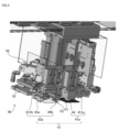
- FIG. 3 is a perspective view schematically showing the periphery of the accommodation mechanism. It is a figure which shows typically the conveyance mechanism seen diagonally from below. It is a figure which shows typically the conveyance mechanism seen diagonally from above.
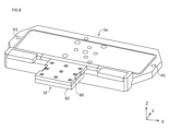
- FIG. 3 is a diagram for explaining the mutual relationship between a substrate transport section, a mounting loader, and a suction source. It is a figure which shows typically the side surface of a part of conveyance mechanism. It is a figure which shows typically the state which looked at the cutting table and the dressing table from diagonally above. It is a figure which shows typically the plane of a member for dress board arrangement
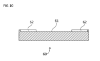
- FIG. 9 is a diagram schematically showing a cross section taken along line XX in FIG. 9.
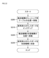
- FIG. 3 is a flowchart illustrating a procedure for automatic dress board replacement processing.
- 12 is a flowchart showing the processing executed in step S110 of FIG. 11. It is a figure which shows the positional relationship of the conveyance mechanism and a table at the timing of collecting
- 12 is a flowchart showing the processing executed in step S120 of FIG. 11. It is a figure which shows the positional relationship of the conveyance mechanism and a table at the timing which arrange
- 12 is a flowchart showing an example in which dress board collection processing and attachment processing are performed in parallel. It is a perspective view which shows typically the periphery of a new dress holder in other embodiments.
- this embodiment according to one aspect of the present invention will be described in detail using the drawings.
- the same reference numerals are attached to the same or corresponding parts in the drawings, and the description thereof will not be repeated.
- each drawing is schematically drawn with objects omitted or exaggerated as appropriate for ease of understanding.
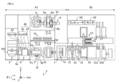
- FIG. 1 is a plan view schematically showing a cutting device 1 according to the present embodiment.
- the cutting device 1 is configured to cut a package substrate (an example of an object to be cut) into pieces into a plurality of electronic components (package components).
- package substrates include those on which a semiconductor chip is mounted or a lead frame sealed with resin, and those on which capacitors, resistors, etc. are sealed with resin.
- the package substrate is the object to be cut, but the object to be cut may be a substrate or a wafer that is not sealed with resin.
- package substrates include BGA (Ball Grid Array) package substrate, LGA (Land Grid Array) package substrate, CSP (Chip Size Package) package substrate, LED (Light Emitting Diode) package substrate, and QFN (Quad Flat No-leaded). ) package substrates.
- the cutting device 1 is configured to inspect each of the plurality of electronic components that have been separated into pieces.
- an image of each electronic component is captured, and each electronic component is inspected based on the image. Inspection data is generated through the inspection, and each electronic component is classified as a "good product” or a "defective product.”
- a package substrate P1 is used as the object to be cut, and the cutting device 1 separates the package substrate P1 into a plurality of electronic components S1.
- the resin-sealed surface will be referred to as a mold surface, and the surface opposite to the mold surface will be referred to as a ball/lead surface.
- the cutting device 1 includes a cutting module A1 and an inspection/storage module B1 as components.
- the cutting module A1 is configured to manufacture a plurality of electronic components S1 by cutting the package substrate P1.
- dressing of a blade 6a (described later) for cutting the package substrate P1 is performed.
- dressing the blade 6a means sharpening the blade 6a.
- dressing of the blade 6a is performed by forming grooves in the dressing board D1 (described later) with the blade 6a.
- the dressing board D1 is automatically replaced. The automatic replacement of the dress board D1 will be explained in detail later.
- the inspection/storage module B1 is configured to inspect each of the plurality of manufactured electronic components S1, and then store the electronic components S1 in a tray.
- each component is removable and replaceable with respect to other components.
- the cutting module A1 mainly includes a substrate supply section 3, a positioning section 4, a table 5, a spindle section 6, and a transport section 7.
- the substrate supply section 3 supplies the package substrates P1 one by one to the positioning section 4 by pushing out the package substrates P1 one by one from the magazine M1 that accommodates a plurality of package substrates P1. At this time, the package substrate P1 is placed with the ball/lead surface facing upward.
- the positioning section 4 includes a rail section 4a, a transport mechanism 4b, and a storage mechanism 43.
- the rail section 4a the package substrate P1 pushed out from the substrate supply section 3 is placed on the rail section 4a, and the package substrate P1 is positioned. Thereafter, the transport mechanism 4b transports the positioned package substrate P1 to the table 5.
- the storage mechanism 43 stores a plurality of dress boards D1 (FIG. 3) in a stacked manner.
- the transport mechanism 4b transports the dress board D1 accommodated in the storage mechanism 43 to the table 5 as necessary. Note that the transport mechanism 4b and the storage mechanism 43 will be explained in detail later.
- the table 5 holds the package substrate P1 to be cut.
- a cutting device 1 having a twin cut table configuration having two tables 5 is illustrated.
- the table 5 includes a cutting table 5a, a dressing table 5f, a rotating mechanism 5b, and a moving mechanism 5c.
- the cutting table 5a holds the package substrate P1 transported by the transport mechanism 4b by adsorbing it from below.
- the dressing table 5f holds the dress board D1 (FIG. 3) transported by the transport mechanism 4b by adsorbing it from below. Although details will be described later, the dressing board D1 held on the dressing table 5f is automatically replaced by the transport mechanism 4b.
- the rotation mechanism 5b is capable of rotating the cutting table 5a and the dressing table 5f in the ⁇ 1 direction in the figure (that is, rotating in the horizontal plane).
- the moving mechanism 5c can move the cutting table 5a and the dressing table 5f along the Y axis in the figure. More specifically, the moving mechanism 5c has a set position (hereinafter also simply referred to as "set position") where the package substrate P1 is held on the cutting table 5a, and a processing position (hereinafter also referred to simply as “set position”) where the package substrate P1 is cut. (also simply referred to as the "processing position").
- the spindle unit 6 separates the package substrate P1 into a plurality of electronic components S1 by cutting the package substrate P1.
- a cutting device 1 having a twin spindle configuration having two spindle sections 6 is illustrated.
- the spindle portion 6 is movable along the X-axis and Z-axis in the figure. Note that the cutting device 1 may have a single spindle configuration having one spindle portion 6.
- the spindle portion 6 includes a blade 6a and a rotating shaft 6c.
- the blade 6a cuts the package substrate P1 by rotating at high speed, and separates the package substrate P1 into a plurality of electronic components S1.
- the blade 6a is mounted on the rotating shaft 6c while being sandwiched between first and second flanges (not shown).
- the first and second flanges are fixed to the rotating shaft 6c by a fastening member (not shown) such as a nut.
- the first flange is also referred to as the inner flange
- the second flange is also referred to as the outer flange.
- dressing of the blade 6a is performed by rotating the blade 6a at high speed to form a groove in the dressing board D1 held on the dressing table 5f. As a result, the blade 6a is sharpened.
- the spindle part 6 is provided with a cutting water nozzle, a cooling water nozzle, an offcut water nozzle, and the like.
- the cutting water nozzle injects cutting water toward the blade 6a rotating at high speed.
- the cooling water nozzle injects cooling water toward the vicinity of the cut portion of the package substrate P1.
- the waste material removal water nozzle sprays waste material removal water that removes cutting waste and the like.
- the package substrate P1 is imaged by the first position confirmation camera 5d, and the position of the package substrate P1 is confirmed.
- the confirmation using the first position confirmation camera 5d is, for example, confirmation of the position of a mark provided on the package substrate P1.
- the mark indicates, for example, the cutting position of the package substrate P1.
- the table 5 moves toward the spindle section 6 along the Y axis in the figure.
- the package substrate P1 is cut by relatively moving the table 5 and the spindle part 6.
- the package board P1 is imaged by the second position confirmation camera 6b provided in the spindle section 6 as needed, and the position of the package board P1 and the like are confirmed.
- the confirmation using the second position confirmation camera 6b is, for example, confirmation of the cutting position and cutting width of the package substrate P1.
- the table 5 moves in a direction away from the spindle part 6 along the Y axis in the figure while adsorbing the plurality of individualized electronic components S1.
- the first cleaner 5e cleans and dries the upper surface (ball/lead surface) of the electronic component S1.
- the first cleaner 5e is provided in an area between the set position and the processing position.
- the cleaning in the first cleaner 5e may be performed, for example, by directly spraying cleaning water (an example of a liquid) onto the top surface of the electronic component S1, or by cleaning the top surface of the electronic component S1 with a brush or the like. This may be done by supplying water.
- the cutting device 1 is provided with two first cleaners 5e arranged in the X-axis direction in the figure, the number of first cleaners 5e is not limited to this.
- the first cleaner 5e may be able to clean the dressing board D1 held on the dressing table 5f.
- the dress board D1 may be cleaned, for example, by directly spraying cleaning water onto the top surface of the dress board D1.
- two fluids including liquid and gas may be directly injected onto the upper surface of the dress board D1.
- the dress board D1 can be cleaned, and the blade 6a can be cleaned using the cleaned dress board D1.
- Dressing can be done.
- the transport unit 7 sucks the electronic component S1 held on the cutting table 5a from above and transports the electronic component S1 to the inspection table 11 of the inspection/storage module B1.
- the second cleaner 7a cleans and dries the lower surface (mold surface) of the electronic component S1.
- This cleaning may be performed, for example, by directly spraying cleaning water onto the bottom surface of the electronic component S1, or by supplying cleaning water to the bottom surface of the electronic component S1 through a brush or the like. Good too.
- the inspection/storage module B1 mainly includes an inspection table 11, a first optical inspection camera 12, a second optical inspection camera 13, an arrangement section 14, and an extraction section 15. Note that the first optical inspection camera 12 may be provided in the cutting module A1.
- the inspection table 11 holds the electronic component S1 for optical inspection of the electronic component S1.
- the inspection table 11 is movable along the X-axis in the figure. Further, the inspection table 11 can be turned upside down.
- the inspection table 11 is provided with a holding member that holds the electronic component S1 by sucking the electronic component S1.
- the first optical inspection camera 12 and the second optical inspection camera 13 image both sides (ball/lead surface and mold surface) of the electronic component S1. Based on the captured images (image data) generated by the first optical inspection camera 12 and the second optical inspection camera 13, various inspections of the electronic component S1 are performed. Each of the first optical inspection camera 12 and the second optical inspection camera 13 is arranged in the vicinity of the inspection table 11 so as to image the upper part.
- the first optical inspection camera 12 images the mold surface of the electronic component S1 that is transported to the inspection table 11 by the transport unit 7. Thereafter, the transport section 7 places the electronic component S1 on the holding member of the inspection table 11. After the holding member adsorbs the electronic component S1, the inspection table 11 is turned upside down. The inspection table 11 moves above the second optical inspection camera 13, and the ball/lead surface of the electronic component S1 is imaged by the second optical inspection camera 13.
- the inspected electronic component S1 is placed in the placement section 14.
- the arrangement section 14 is movable along the Y axis in the figure.
- the inspection table 11 places the inspected electronic component S1 in the placement section 14.
- the extraction unit 15 transfers the electronic component S1 placed in the placement unit 14 to the tray.
- the electronic components S1 are classified into “defective products” or “defective products” based on the results of inspection using the first optical inspection camera 12 and the second optical inspection camera 13.
- the extraction unit 15 transfers each electronic component S1 to the non-defective tray 15a or the defective tray 15b based on the classification results. That is, non-defective products are stored in the tray 15a for non-defective products, and defective products are stored in the tray 15b for defective products. Once each of the non-defective tray 15a and the defective tray 15b is filled with electronic components S1, they are replaced with new trays.
- the cutting device 1 further includes a computer 50 and a monitor 20.
- Monitor 20 is configured to display images.
- the monitor 20 is configured with a display device such as a liquid crystal monitor or an organic EL (Electro Luminescence) monitor.
- the computer 50 controls, for example, the operation of each part of the cutting module A1 and the inspection/storage module B1.
- the computer 50 controls, for example, the substrate supply section 3, the positioning section 4, the table 5, the spindle section 6, the transport section 7, the inspection table 11, the first optical inspection camera 12, the second optical inspection camera 13, the arrangement section 14, and the extraction section. 15 and monitor 20 are controlled.
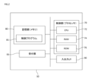
- FIG. 2 is a diagram schematically showing the hardware configuration of the computer 50.
- the computer 50 includes a control section 70, an input/output I/F (interface) 90, a reception section 95, and a storage section 80, and each component is electrically connected via a bus. It is connected to the.
- the control unit 70 includes a CPU (Central Processing Unit) 72, a RAM (Random Access Memory) 74, a ROM (Read Only Memory) 76, and the like.
- the control unit 70 is configured to control each component in the computer 50 and each component in the cutting device 1 according to information processing.
- the input/output I/F 90 is configured to communicate with each component included in the cutting device 1 via a signal line.
- the input/output I/F 90 is used to transmit data from the computer 50 to each component in the cutting device 1 and to receive data transmitted from each component in the cutting device 1 to the computer 50.
- the reception unit 95 is configured to receive instructions from a user (worker).
- the reception unit 95 includes, for example, a touch panel, a keyboard, a mouse, and a portion or all of a microphone.
- the storage unit 80 is, for example, an auxiliary storage device such as a hard disk drive or a solid state drive.
- the storage unit 80 is configured to store a control program 81, for example.
- a control program 81 By executing the control program 81 by the control unit 70, various operations in the cutting device 1 are realized.
- the control unit 70 executes the control program 81, the control program 81 is loaded into the RAM 74.
- the control unit 70 controls each component by having the CPU 72 interpret and execute the control program 81 loaded in the RAM 74.
- the cutting device 1 is provided with the dressing table 5f configured to hold the dressing board D1, and the dressing board D1 held by the dressing table 5f is automatically replaced. The reason for this will be explained next.
- the dressing table 5f it is conceivable to dress the blade 6a by arranging the dressing board D1 on the cutting table 5a. Furthermore, it is conceivable to arrange the dress board D1 manually. In such a case, the operator will temporarily stop the cutting device 1 and manually place the dress board D1 on the cutting table 5a. Since such work requires a certain amount of time, it takes a long time to dress the dressing board D1.
- the dressing table 5f that holds the dressing board D1 is provided separately from the cutting table 5a, and the dressing board D1 held on the dressing table 5f is replaced by the transport mechanism 4b. done automatically. Therefore, according to the cutting device 1, the dressing board D1 is basically held on the dressing table 5f, and even when the dressing board D1 needs to be replaced, the dressing board D1 can be replaced automatically. Therefore, the time required for dressing the dressing board D1 can be shortened.
- Each mechanism related to automatic replacement of the dress board D1 will be described in detail below.
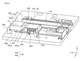
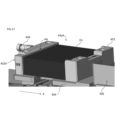
- FIG. 3 is a perspective view schematically showing the periphery of the accommodation mechanism 43. As shown in FIG. 3, the accommodation mechanism 43 is provided at a position adjacent to the rail portion 4a.
- the storage mechanism 43 includes a new dress holder 43a and a used dress box 43b.
- the new dress holder 43a is configured to stack and accommodate a plurality of new dress boards D1.
- the new dress holder 43a is assembled to a base portion 436, and includes a movable block 432 and a fixed block 433.
- the base portion 436 is a plate-shaped member whose bottom is raised by a plurality of legs.
- the fixed block 433 is fixed on the base part 436.
- a protrusion 437 that protrudes toward the movable block 432 in the X-axis direction is provided at each of both ends of the fixed block 433 in the Y-axis direction.
- the length between the two protrusions 437 is approximately the same as the length of the corresponding side of the dress board D1.
- the two protrusions 437 determine the position of the dress board D1 in the Y-axis direction with high precision.
- the movable block 432 has a movable range in the X-axis direction on the base portion 436.
- the movable block 432 can be fixed at a desired position within the movable range. By determining the position of the movable block 432, the position of the dress board D1 in the X-axis direction can be determined with high precision.
- a sensor 434 is attached to the lower surface of the base portion 436.
- the sensor 434 is composed of, for example, a reflective sensor.
- the dress board D1 housed lowest is exposed to the sensor 434 side.
- the sensor 434 detects whether or not the dress board D1 remains in the new dress holder 43a by emitting light toward the new dress holder 43a and detecting the presence or absence of reflected light, for example. For example, when the new dress holder 43a is empty, the cutting device 1 may generate a warning sound.
- the used dress box 43b is configured to stack and accommodate a plurality of used dress boards D1. For example, when the number of dress boards D1 housed in the used dress box 43b reaches a predetermined number, the used dress box 43b is replaced with a new empty one.
- the used dress box 43b is a box-shaped member with an open top. The used dress box 43b is placed on the base portion 436.
- the used dress box 43b includes a bottom portion 430 and side wall portions 431a, 431b, 431c, and 431d.
- a plurality of used dress boards D1 are accommodated in the space surrounded by the side walls 431a, 431b, 431c, and 431d.
- the side walls 431a and 431c face each other, and the side walls 431b and 431d face each other.
- a notch C1 is formed at the upper end of each of the side walls 431b and 431d. The reason why the notch portion C1 is formed at the upper end of each of the side wall portions 431b and 431d will be explained later.
- a sensor 435 is attached to the lower surface of the base portion 436.
- the sensor 435 is composed of, for example, a reflective sensor. At least a portion of the lower surface of the used dress box 43b is exposed to the sensor 435 side.
- the sensor 435 detects whether or not the used dress box 43b is present at a predetermined position, for example, by emitting light toward the used dress box 43b and detecting the presence or absence of reflected light. For example, when the used dressing box 43b is not present at a predetermined position, the cutting device 1 may generate a warning sound.
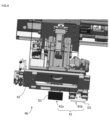
- FIG. 4 is a diagram schematically showing the transport mechanism 4b as seen diagonally from below.
- FIG. 5 is a diagram schematically showing the transport mechanism 4b as viewed diagonally from above.
- the transport mechanism 4b includes a substrate transport section 42 and a dress board transport section 41.
- the attachment loader 41a and the recovery loader 41b are each shown holding the dress board D1, and in particular, the recovery loader 41a and the recovery loader 41b are shown holding the dress board D1.
- the dress board D1 held by the loader 41b is shown transparent.
- the substrate conveyance section 42 is configured to suck the package substrate P1 positioned on the rail section 4a (FIG. 1) and convey the sucked package substrate P1 to the cutting table 5a.
- the substrate transport section 42 is connected to a suction source 65 (FIG. 6) such as a vacuum ejector via a connecting member 66.
- the suction source 65 will be explained later.
- the dress board transport section 41 includes an attachment loader 41a and a recovery loader 41b.
- the attachment loader 41a and the recovery loader 41b are provided at positions adjacent to each other in the X-axis direction (see FIG. 1).
- the dress board transport unit 41 is integrated with the board transport unit 42 and is configured to move in the X direction together with the board transport unit 42.
- the mounting loader 41a suctions the dress board D1 located uppermost among the plurality of dress boards D1 housed in the new dress holder 43a (FIG. 3), and dresses the suctioned dress board D1 from the new dress holder 43a. It is configured to transport the paper to the table 5f for use.
- the mounting loader 41a is connected to a suction source 65 such as a vacuum ejector via a connecting member 66.
- FIG. 6 is a diagram for explaining the mutual relationship between the substrate transport section 42, the mounting loader 41a, and the suction source 65.
- the substrate transport section 42 and the mounting loader 41a are each connected to a common suction source 65 via a switching valve V1.
- a state in which the substrate transport unit 42 and the suction source 65 are connected, and a state in which the mounting loader 41a and the suction source 65 are connected can be changed.
- the cutting device 1 since the suction source for suctioning the package substrate P1 and the suction source for suctioning the dress board D1 are common, an increase in the number of suction sources can be suppressed. As a result, according to the cutting device 1, it is possible to suppress the device from increasing in size.
- the mounting loader 41a includes an air cylinder 411a and a vacuum pad 44.
- the air cylinder 411a can be expanded and contracted in the vertical direction, and is configured to move the vacuum pad 44 in the vertical direction.
- the vacuum pad 44 is lowered and the dress board D1 is attracted to the dress board D1 while the vacuum pad 44 is in contact with the dress board D1. Thereby, the dress board D1 is held by the mounting loader 41a. Further, by connecting a pressure reducing valve to the air cylinder 411a, it is possible to appropriately pick up the dress boards D1 regardless of the number of dress boards D1 remaining in the new dress holder 43a.
- the recovery loader 41b is configured to mechanically hold the used dress board D1 held on the dressing table 5f and transport the held dress board D1 from the dressing table 5f to the used dress box 43b. has been done. The reason why the new dress board D1 is held by suction while the used dress board D1 is not held by suction but is held mechanically will be explained next.
- a large number of grooves are formed on the used dress board D1.
- the dress board D1 may not be stably held due to suction of the surface on which many grooves are formed. That is, holding of the used dress board D1 may become unstable.
- a new (unused) dress board D1 is suction-held by the mounting loader 41a, and a used dress board D1 is mechanically held by the recovery loader 41b. Therefore, according to the cutting device 1, since the new dress board D1 is held by suction, it is possible to suppress a decrease in the positional accuracy of the new dress board D1. Further, according to the cutting device 1, since the used dress board D1 is mechanically held, the used dress board D1 can be held stably.
- FIG. 7 is a diagram schematically showing a side surface of a portion of the transport mechanism 4b.
- recovery loader 41b includes an air cylinder 411b and claw portions 49a, 49b.
- the air cylinder 411b can be expanded and contracted in the vertical direction, and is configured to move the claws 49a and 49b in the vertical direction.
- the claw portions 49a and 49b face each other in the horizontal direction (X-axis direction).
- the claw portions 49a and 49b are configured to move in a direction toward each other and in a direction in which they move away from each other. That is, a pair of claws (hereinafter also simply referred to as a "pair of claws") constituted by the claws 49a and 49b are configured to open and close in the horizontal direction.
- the recovery loader 41b mechanically holds the dress board D1 by sandwiching the dress board D1 between a pair of claws.
- the claw portion 49a includes a claw 45a, a linear bush 47a, an air chuck 46a, and a spring 48a.
- the claw 45a is a plate-shaped member that has a width in the Y-axis direction and extends in the Z-axis direction. The lower end of the claw 45a is bent toward the claw 45b.
- the pawl 45a is attached to a linear bush 47a.
- a shaft extending in the X-axis direction passes through the linear bush 47a, and the linear bush 47a is configured to move on the shaft.
- a spring 48a is provided in a direction opposite to the direction in which the claw 45a exists with respect to the linear bush 47a.
- the air chuck 46a is configured to move in the X-axis direction.
- Linear bush 47a is attached to air chuck 46a.
- the claw portion 49b includes a claw 45b, a linear bush 47b, an air chuck 46b, and a spring 48b.
- the claw 45b is a plate-shaped member that has a width in the Y-axis direction and extends in the Z-axis direction. The lower end of the claw 45b is bent toward the claw 45a.
- the pawl 45b is attached to the linear bush 47b.
- a shaft extending in the X-axis direction passes through the linear bush 47b, and the linear bush 47b is configured to move on the shaft.
- a spring 48b is provided in a direction opposite to the direction in which the claw 45b exists with respect to the linear bush 47b.
- the air chuck 46b is configured to move in the X-axis direction.
- Linear bush 47b is attached to air chuck 46b.
- FIG. 8 is a diagram schematically showing the state in which the cutting table 5a and the dressing table 5f are viewed diagonally from above.
- the dressing table 5f is provided at a position adjacent to the cutting table 5a, and is fixed to the cutting table 5a.
- the dressing table 5f includes a base portion 63 and a dressing board arrangement member 60 fixed on the base portion 63.
- the dress board arrangement member 60 is made of an elastic member such as rubber, and is replaceable.
- the dress board D1 is arranged on the dress board arrangement member 60.
- the dress board D1 is held by suction on the dress board arrangement member 60.
- FIG. 9 is a diagram schematically showing a plane of the dress board arrangement member 60.
- FIG. 10 is a diagram schematically showing a cross section taken along line XX in FIG. Referring to FIGS. 9 and 10, the dress board arrangement member 60 has a bottom portion 61. As shown in FIG. A plurality of holes H2 are formed on the bottom surface part 61. Suction of the dress board D1 is performed through the hole H2. A notch C2 is formed in each of a pair of opposing sides of the plurality of sides of the bottom surface portion 61. The reason why the notch C2 is formed will be explained later.
- a protrusion 62 extending upward is formed on a portion of the outer periphery of the bottom surface portion 61 other than the portion where the cutout portion C2 is formed.
- Dress board D1 is arranged within the area surrounded by protrusion 62. Note that the shape and size of the dress board D1 in a plan view are substantially the same as the shape and size of the area surrounded by the protrusion 62 in a plan view.
- FIG. 11 is a flowchart showing the procedure for automatic replacement processing of the dress board D1.
- the processing shown in this flowchart is executed by the control unit 70 (FIG. 2) of the computer 50 when it is necessary to attach or replace the dress board D1.
- the control unit 70 places the used dress board D1 on the dressing table 5f by referring to the output of a sensor (not shown) that detects the suction state on the dressing table 5f, for example. It is determined whether or not there exists (step S100). If it is determined that there is no used dressing board D1 on the dressing table 5f (NO in step S100), the control unit 70 executes the process of step S120.
- step S100 determines that there is a used dress board D1 on the dressing table 5f (YES in step S100).
- the control unit 70 executes a collection process for the used dress board D1 (step S110).
- the recovery process for the dress board D1 will be explained in detail later.
- the control unit 70 executes the process of attaching a new dress board D1 (step S120). The process of attaching the dress board D1 will be explained in detail later.
- FIG. 12 is a flowchart showing the process executed in step S110 (recovery process of dress board D1) in FIG.
- the control unit 70 controls the drive unit (eg, motor) of the transport mechanism 4b so that the recovery loader 41b is positioned above the dressing table 5f (step S200). After that, the control unit 70 controls the pair of claws so that the pair of claws of the collection loader 41b descend and pick up the used dressing board D1 held on the dressing table 5f. (step S210).
- the drive unit eg, motor
- the pair of claws of the recovery loader 41b is lowered in an open state, and then the dress included in the dressing table 5f is closed. A pair of claws enters the notch C2 of the board placement member 60. The dress board D1 is picked up by raising the pair of claws while entering the notch C2.
- FIG. 13 is a diagram showing the positional relationship between the transport mechanism 4b and the table 5 at the timing of collecting the dressing board D1 held on the dressing table 5f.
- the collecting loader 41b is located above the dressing table 5f.
- the substrate transport section 42 and the cutting table 5a do not overlap. The reason why the dress board D1 is collected in such a positional relationship will be explained next.
- the substrate transport section 42 is provided with a pin PI1 extending downward, and the cutting table 5a is provided with a hole H1 into which the pin PI1 enters.
- the package substrate P1 is moved by the substrate transfer section 42 for cutting with the pin PI1 of the substrate transfer section 42 entering the hole H1 of the cutting table 5a. It is placed on the table 5a. If the recovery loader 41b attempts to recover the dress board D1 in a state where the substrate transfer section 42 and the cutting table 5a overlap in plan view, the pins PI1 of the substrate transfer section 42 will get in the way.
- the dress board D1 is collected by the collection loader 41b in a state where the substrate transport section 42 and the cutting table 5a do not overlap in a plan view, so that the dress board D1 can be collected appropriately. I can do it.
- the control unit 70 controls the drive unit of the transport mechanism 4b so that the collection loader 41b is positioned above the used dress box 43b. (Step S220). Thereafter, the control unit 70 controls the collection loader 41b so that the pair of claws descends and enters each notch C1 (FIG. 3) formed in the used dress box 43b. The drive units for the pair of claws are controlled so that the claws open (step S230). Thereby, the used dress board D1 is stored in the used dress box 43b. Since the pair of claws are opened with each claw entering each notch C1 (FIG. 3) formed in the used dress box 43b, the used dress board D1 is placed inside the used dress box 43b. The possibility of not falling is reduced.
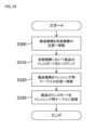
- FIG. 14 is a flowchart showing the process executed in step S120 (attachment process of dress board D1) in FIG. 11.
- the control unit 70 controls the drive unit of the transport mechanism 4b so that the mounting loader 41a is positioned above the new dress holder 43a (step S300).
- the control unit 70 controls the drive unit of the mounting loader 41a so that the vacuum pad 44 of the mounting loader 41a descends and the vacuum pad 44 suction-holds the new dress board D1 housed in the new dress holder 43a. control (step S310).
- the control unit 70 controls the drive unit of the transport mechanism 4b so that the mounting loader 41a is positioned above the dressing table 5f (step S320). After that, the control unit 70 controls the drive unit of the mounting loader 41a so that the vacuum pad 44 is lowered and the vacuum pad 44 places the dressing board D1 on the dressing table 5f (step S330).
- FIG. 15 is a diagram showing the positional relationship between the transport mechanism 4b and the table 5 at the timing when a new dressing board D1 is placed on the dressing table 5f.
- the mounting loader 41a is positioned above the dressing table 5f at the timing when a new dressing board D1 is placed on the dressing table 5f.
- the substrate transport section 42 and the cutting table 5a do not overlap.
- the dressing board D1 is not affected by the pin PI1.
- the dress board D1 can be appropriately placed on the table 5f.
- the transport mechanism 4b includes the dress board transport section 41.
- the dress board transport unit 41 automatically transports the dress board D1 between the storage mechanism 43 and the dressing table 5f. Therefore, according to the cutting device 1, since the dressing board D1 is automatically transported between the storage mechanism 43 and the dressing table 5f, the dressing board D1 attached to the dressing table 5f can be automatically replaced. As a result, the cutting device 1 can shorten the time required to replace the dress board D1.
- the cutting device 1 is an example of a "cutting device” in the present invention.
- the cutting table 5a is an example of a “cutting table” in the present invention.
- the spindle portion 6 is an example of a “cutting mechanism” in the present invention.
- the dressing table 5f is an example of a "dressing table” in the present invention.
- the accommodation mechanism 43 is an example of the "accommodation mechanism” in the present invention.
- the transport mechanism 4b is an example of a "transport mechanism” in the present invention.
- the substrate transport section 42 is an example of a "substrate transport section” in the present invention.
- the dress board transport section 41 is an example of a "dress board transport section” in the present invention.
- the mounting loader 41a is an example of the "mounting loader” in the present invention.
- the collection loader 41b is an example of a “recovery loader” in the present invention.
- the suction source 65 is an example of a "suction source” in the present invention.
- Each of the claw parts 49a and 49b is an example of a "claw part” in the present invention.
- the new dress holder 43a is an example of the "first accommodating part” in the present invention.
- the used dress box 43b is an example of a “second storage section” in the present invention.
- the moving mechanism 5c is an example of a "moving mechanism” in the present invention.
- the first cleaner 5e is an example of a "cleaning section” in the present invention.
- FIG. 16 is a flowchart showing an example in which the collection process and the attachment process of the dress board D1 are performed in parallel.
- the processing shown in this flowchart may be executed by the control unit 70, for example.
- control unit 70 controls the drive unit of the transport mechanism 4b so that the mounting loader 41a is positioned above the new dress holder 43a (step S400).
- the control unit 70 controls the drive unit of the mounting loader 41a so that the vacuum pad 44 of the mounting loader 41a descends and the vacuum pad 44 suction-holds the new dress board D1 housed in the new dress holder 43a. control (step S405).
- the control unit 70 determines whether or not there is a used dress board D1 on the dressing table 5f, for example, by referring to the output of a sensor (not shown) that detects the suction state on the dressing table 5f. Determination is made (step S410). If it is determined that there is no used dressing board D1 on the dressing table 5f (NO in step S410), the control unit 70 executes the process of step S425.
- step S410 the control unit 70 transports the collection loader 41b so that it is located above the dressing table 5f.
- the drive section of the mechanism 4b is controlled (step S415).
- the control unit 70 controls the pair of claws so that the pair of claws of the collection loader 41b descend and pick up the used dressing board D1 held on the dressing table 5f. (step S420).
- the control unit 70 controls the drive unit of the transport mechanism 4b so that the mounting loader 41a is positioned above the dressing table 5f (step S425). After that, the control unit 70 controls the drive unit of the mounting loader 41a so that the vacuum pad 44 is lowered and the vacuum pad 44 places the dressing board D1 on the dressing table 5f (step S430). Thereafter, the control unit 70 controls the drive unit of the transport mechanism 4b so that the collection loader 41b is positioned above the used dress box 43b (step S435).
- the control unit 70 determines whether the collection loader 41b holds the used dress board D1 by referring to the output of a sensor (not shown) provided on the collection loader 41b (step S440). If it is determined that the collection loader 41b does not hold the used dress board D1 (NO in step S440), the process shown in this flowchart ends. On the other hand, if it is determined that the recovery loader 41b is holding the used dress board D1 (YES in step S440), the control unit 70 causes the pair of claws of the recovery loader 41b to descend so that the used dress board D1 is not used. With each claw entering each notch C1 (FIG. 3) formed in the finished dressing box 43b, the driving parts of the pair of claws are controlled so that the pair of claws open (step S445). Thereby, the used dress board D1 is stored in the used dress box 43b.
- the collection loader 41b is configured to mechanically hold the used dress board D1.
- the recovery loader 41b does not necessarily have to mechanically hold the dress board D1.
- the recovery loader 41b may hold the dress board D1 by suction.
- the substrate transport section 42 and the mounting loader 41a are connected to a common suction source 65.
- the substrate transport section 42 and the mounting loader 41a do not necessarily need to be connected to the common suction source 65.
- the suction source connected to the substrate transport section 42 and the suction source connected to the attachment loader 41a may be different.
- the structure of the new dress holder is not limited to the structure of the new dress holder 43a in the above embodiment.
- the structure of the new dress holder may be as described below.
- FIG. 17 is a perspective view schematically showing the vicinity of a new dress holder 43aA in another embodiment.
- the new dress holder 43aA is configured to accommodate a plurality of dress boards D1 in a stacked manner.
- the new dress holder 43aA accommodates two dress boards D1 less than the maximum number of sheets accommodated (one example).
- the new dress holder 43aA is assembled to the base portion 436 and includes a movable block 432A and a fixed block 433.
- the movable block 432A has a movable range in the X-axis direction on the base portion 436.
- the movable block 432A can be fixed at a desired position within the movable range.
- the movable block 432A is formed with a through hole H4 that penetrates in the thickness direction (X-axis direction) of the movable block 432A.
- a through hole H4 is formed at the boundary between the uppermost dress board D1 and the second dress board D1 from the top. The center is located.
- a pipe 438 is connected to the through hole H4, and compressed air is sent to the through hole H4 through the pipe 438.
- the mounting loader 41a suction-holds the dress board D1 housed in the new dress holder 43a
- the discharge of compressed air from the through hole H4 is started.
- the dress board D1 rises to the position of the through hole H4 while being held by the attachment loader 41a
- the discharge of compressed air from the through hole H4 is stopped. Thereafter, the conveyance of the dress board D1 is continued.
- a wet dress board D1 may be unintentionally accommodated in the new dress holder 43aA.
- the plurality of dress boards D1 may stick to each other, and the plurality of dress boards D1 may be lifted up by suction and holding of the dress boards D1 by the attachment loader 41a.
- the board D1 can be dropped into the new dress holder 43aA. That is, according to such a configuration, it is possible to suppress the occurrence of a situation in which a plurality of new dress boards D1 are unintentionally transported.
- composition a cutting table configured to hold an object to be cut; a cutting mechanism configured to cut the object to be cut held on the cutting table with a blade; a dressing table configured to hold a dressing board for dressing the blade; a storage mechanism configured to stack and store a plurality of the dress boards;
- a transport mechanism including a substrate transport section and a dress board transport section that moves together with the substrate transport section, The substrate conveyance unit is configured to suck the object to be cut and to convey the attracted object to be cut to the cutting table,
- the dress board transport section is a cutting device configured to transport the dress board between the accommodation mechanism and the dressing table.
- the transport mechanism includes a dress board transport section.
- the dress board transport section automatically transports the dress board between the storage mechanism and the dressing table. Therefore, according to this cutting device, since the dressing board is automatically transported between the storage mechanism and the dressing table, the dressing board attached to the dressing table can be automatically replaced.
- the dress board conveyance section is an attachment loader configured to adsorb the unused dress board accommodated in the accommodation mechanism and to transport the adsorbed dress board from the accommodation mechanism to the dressing table;
- Technique 1 includes a recovery loader configured to mechanically hold the used dressing board and to transport the mechanically held dressing board from the dressing table to the storage mechanism. Cutting device as described.
- unused dress boards are suction-held by an attachment loader, and used dress boards are mechanically held by a recovery loader. Therefore, according to this cutting device, since the unused dress board is held by suction, it is possible to suppress a decrease in the positional accuracy of the unused dress board. Further, since many grooves are formed on the surface of the used dress board, suction and holding of the used dress board may become unstable. According to this cutting device, since the used dress board is mechanically held, the used dress board can be held stably.
- the recovery loader includes a pair of claws facing each other in the horizontal direction, The pair of claws are configured to open and close in a horizontal direction, The cutting device according to technique 2 or technique 3, wherein the recovery loader is configured to mechanically hold the dress board by sandwiching the dress board between the pair of claws.
- the accommodation mechanism is a first accommodating portion configured to accommodate the unused dress board; a second storage portion configured to receive the used dress board;
- the shape of the first accommodating part is different from the shape of the second accommodating part,
- the second accommodating portion includes a plurality of side wall portions,
- the used dress board is housed in a space surrounded by the plurality of side walls,
- the cutting device according to technique 4 wherein a notch is formed at an upper end of each of two opposing side wall portions among the plurality of side wall portions.
- the shape of the first accommodation part and the shape of the second accommodation part are different, and a notch is formed at the upper end of each of two opposing side walls of the plurality of side walls of the second accommodation part. ing.
- the pair of claws of the collection loader enters into the notch, opens the pair of claws, and drops the used dressboard, thereby ensuring that the used dressboard is placed in the first place. It can be accommodated in two accommodating parts.
- composition a movement mechanism configured to move both the cutting table and the dressing table; further comprising a cleaning section configured to clean each of the object to be cut and the dress board,
- the moving mechanism is configured to move between a set position where the object to be cut is held on the cutting table and a processing position where the object to be cut is subjected to a cutting process,
- the cutting device according to any one of techniques 1 to 5, wherein the cleaning section is provided in an area between the set position and the processing position.
- a cleaning section is provided in an area between a set position and a processing position. Therefore, according to this cutting device, the cleaning section can clean the dressing board held by the dressing table. As a result, with this cutting device, even if, for example, machining waste generated during the cutting process of the object to be cut adheres to the dress board, the dress board can be cleaned, and the dress board after cleaning can be cleaned. can be used to dress the blade.
- the dressing board held by the dressing table can be cleaned using at least the liquid.
- the substrate transfer unit includes pins extending downward, A hole is formed in the cutting table, The substrate transport unit is configured to hold the object to be cut on the cutting table in a state in which the pin enters the hole, Technique 1, wherein the dress board transfer unit is configured to transfer the dress board to and from the dressing table in a state where the substrate transfer unit and the cutting table do not overlap in plan view.
- Technique 1 wherein the dress board transfer unit is configured to transfer the dress board to and from the dressing table in a state where the substrate transfer unit and the cutting table do not overlap in plan view.
- the object to be cut in order to ensure positional accuracy of the object to be cut, the object to be cut is placed on the cutting table with the pins of the substrate transport section entering the holes of the cutting table. If the dressing board is transferred between the dressing board transporting part and the dressing table with the board transporting part and the cutting table overlapping in plan view, the pins of the board transporting part may get in the way. There is. According to this cutting device, the dress board is transferred between the dress board transfer section and the dressing table in a state where the substrate transfer section and the cutting table do not overlap in a plan view, so that the dress board is transferred and received appropriately. can be done.
- composition A method for manufacturing a cut product using the cutting device according to any one of techniques 1 to 8, comprising: adsorbing the object to be cut and transporting the adsorbed object to be cut to the cutting table; transporting the dressing board between the storage mechanism and the dressing table; dressing the blade using the dressing board held on the dressing table; A method for manufacturing a cut product, the method comprising: cutting the object to be cut held on the cutting table using the dressed blade to produce the cut product.
- the dressing board is automatically transported between the storage mechanism and the dressing table. Therefore, according to this method for manufacturing cut products, since the dressing board is automatically transported between the storage mechanism and the dressing table, the dressing board attached to the dressing table can be automatically replaced.
Landscapes
- Engineering & Computer Science (AREA)
- Mechanical Engineering (AREA)
- Grinding-Machine Dressing And Accessory Apparatuses (AREA)
- Finish Polishing, Edge Sharpening, And Grinding By Specific Grinding Devices (AREA)
- Dicing (AREA)
- Container, Conveyance, Adherence, Positioning, Of Wafer (AREA)
- Control Of Cutting Processes (AREA)
Abstract
Description
<1-1.切断装置の全体構成>
図1は、本実施の形態に従う切断装置1を模式的に示す平面図である。切断装置1は、パッケージ基板(切断対象物の一例)を切断することによって、該パッケージ基板を複数の電子部品(パッケージ部品)に個片化するように構成されている。パッケージ基板の一例としては、半導体チップが装着された基板又はリードフレームが樹脂封止されたもの、及び、コンデンサ、抵抗等が樹脂封止されたものが挙げられる。また、本実施の形態では、パッケージ基板を切断対象物としているが、樹脂封止されていない基板又はウエーハが切断対象物であってもよい。
図2は、コンピュータ50のハードウェア構成を模式的に示す図である。図2に示されるように、コンピュータ50は、制御部70と、入出力I/F(interface)90と、受付部95と、記憶部80とを含み、各構成は、バスを介して電気的に接続されている。
上述のように、切断装置1においては、ドレスボードD1を保持するように構成されたドレッシング用テーブル5fが設けられており、ドレッシング用テーブル5fに保持されるドレスボードD1の自動交換が行なわれる。この理由について次に説明する。
図3は、収容機構43の周辺を模式的に示す斜視図である。図3に示されるように、収容機構43は、レール部4aに隣接する位置に設けられている。収容機構43は、新品ドレスホルダ43aと、使用済ドレスボックス43bとを含んでいる。
図4は、斜め下方から見た搬送機構4bを模式的に示す図である。図5は、斜め上方から見た搬送機構4bを模式的に示す図である。図4及び図5を参照して、搬送機構4bは、基板搬送部42と、ドレスボード搬送部41とを含んでいる。なお、図4及び図5の各々においては、理解を容易にするために、取付用ローダ41a及び回収用ローダ41bの各々がドレスボードD1を保持した状態が表わされており、特に、回収用ローダ41bによって保持されているドレスボードD1は透明にして表わされている。
図8は、切断用テーブル5a及びドレッシング用テーブル5fを斜め上方から見た状態を模式的に示す図である。図8に示されるように、ドレッシング用テーブル5fは、切断用テーブル5aに隣接する位置に設けられており、切断用テーブル5aに対して固定されている。ドレッシング用テーブル5fは、ベース部63と、ベース部63上に固定されたドレスボード配置用部材60とを含む。ドレスボード配置用部材60は、例えば、ゴム等の弾性部材によって構成されており、交換可能である。ドレスボードD1は、ドレスボード配置用部材60上に配置される。ドレスボード配置用部材60上において、ドレスボードD1は吸着保持される。
図11は、ドレスボードD1の自動交換処理の手順を示すフローチャートである。このフローチャートに示される処理は、ドレスボードD1の取付け又は交換が必要な場合に、コンピュータ50の制御部70(図2)によって実行される。
以上のように、本実施の形態に従う切断装置1においては、搬送機構4bにドレスボード搬送部41が含まれている。ドレスボード搬送部41は、収容機構43及びドレッシング用テーブル5f間において、ドレスボードD1を自動搬送する。したがって、切断装置1によれば、ドレスボードD1が収容機構43及びドレッシング用テーブル5f間で自動搬送されるため、ドレッシング用テーブル5fに取り付けられるドレスボードD1を自動的に交換することができる。その結果、切断装置1によればドレスボードD1の交換に要する時間を短縮することができる。
上記実施の形態の思想は、以上で説明された実施の形態に限定されない。以下、上記実施の形態の思想を適用できる他の実施の形態の一例について説明する。
上記実施の形態においては、ドレスボードD1の自動交換において、使用済みのドレスボードD1の回収処理が終了した後に、新品のドレスボードD1の取付け処理が実行された。しかしながら、これらの処理手順はこれに限定されない。例えば、これらの処理は並行して実行されてもよい。
また、上記実施の形態において、回収用ローダ41bは、使用済みのドレスボードD1を機械的に保持することとした。しかしながら、回収用ローダ41bは、必ずしもドレスボードD1を機械的に保持しなくてもよい。例えば、ドレスボードD1に形成される溝が浅い場合又はドレスボードD1が軽量である場合等においては、回収用ローダ41bが吸引によってドレスボードD1を保持してもよい。
また、上記実施の形態においては、基板搬送部42と取付用ローダ41aとは共通の吸引源65に接続されていた。しかしながら、基板搬送部42と取付用ローダ41aとは必ずしも共通の吸引源65に接続されていなくてもよい。基板搬送部42に接続される吸引源と取付用ローダ41aに接続される吸引源とは異なるものであってもよい。
また、新品ドレスホルダの構造は、上記実施の形態における新品ドレスホルダ43aの構造に限定されない。例えば、新品ドレスホルダの構造は、以下に説明するような構造であってもよい。
[5.付記]
(構成)
切断対象物を保持するように構成された切断用テーブルと、
前記切断用テーブルに保持された前記切断対象物をブレードによって切断するように構成された切断機構と、
前記ブレードのドレッシングのためにドレスボードを保持するように構成されたドレッシング用テーブルと、
複数の前記ドレスボードを積層して収容するように構成された収容機構と、
基板搬送部と、前記基板搬送部と共に移動するドレスボード搬送部とを含む搬送機構とを備え、
前記基板搬送部は、前記切断対象物を吸着すると共に、吸着された前記切断対象物を前記切断用テーブルへ搬送するように構成されており、
前記ドレスボード搬送部は、前記収容機構及び前記ドレッシング用テーブル間において、前記ドレスボードを搬送するように構成されている、切断装置。
この切断装置においては、搬送機構にドレスボード搬送部が含まれている。ドレスボード搬送部は、収容機構及びドレッシング用テーブル間において、ドレスボードを自動搬送する。したがって、この切断装置によれば、ドレスボードが収容機構及びドレッシング用テーブル間で自動搬送されるため、ドレッシング用テーブルに取り付けられるドレスボードを自動的に交換することができる。
(構成)
前記ドレスボード搬送部は、
前記収容機構に収容された未使用の前記ドレスボードを吸着すると共に、吸着された前記ドレスボードを前記収容機構から前記ドレッシング用テーブルへ搬送するように構成された取付用ローダと、
使用済みの前記ドレスボードを機械的に保持すると共に、機械的に保持された前記ドレスボードを前記ドレッシング用テーブルから前記収容機構へ搬送するように構成された回収用ローダとを含む、技術1に記載の切断装置。
この切断装置においては、未使用のドレスボードが取付用ローダによって吸着保持され、使用済みのドレスボードが回収用ローダによって機械的に保持される。したがって、この切断装置によれば、未使用のドレスボードが吸着によって保持されるため、未使用のドレスボードの位置精度の低下を抑制することができる。また、使用済みのドレスボードの表面には多数の溝が形成されているため、使用済みのドレスボードの吸着保持は不安定になる場合がある。この切断装置によれば、使用済みのドレスボードが機械的に保持されるため、使用済みのドレスボードの保持を安定的に行なうことができる。
(構成)
前記基板搬送部による前記切断対象物の吸着における吸引源と、前記取付用ローダによる前記ドレスボードの吸着における吸引源とは共通である、技術2に記載の切断装置。
この切断装置によれば、切断対象物の吸着における吸引源とドレスボードの吸着における吸引源とが共通であるため、吸引源の数の増加を抑制することができる。その結果、この切断装置によれば、装置の大型化を抑制することができる。
(構成)
前記回収用ローダは、水平方向において互いに対向する一対の爪部を含み、
前記一対の爪部は、水平方向において開閉するように構成されており、
前記回収用ローダは、前記一対の爪部によって前記ドレスボードを挟むことにより前記ドレスボードを機械的に保持するように構成されている、技術2又は技術3に記載の切断装置。
この切断装置によれば、使用済みのドレスボードが一対の爪部で挟まれて機械的に保持されるため、使用済みのドレスボードの保持を安定的に行なうことができる。
(構成)
前記収容機構は、
未使用の前記ドレスボードを収容するように構成された第1収容部と、
使用済みの前記ドレスボードを収容するように構成された第2収容部とを含み、
前記第1収容部の形状と、前記第2収容部の形状とは異なり、
前記第2収容部は、複数の側壁部を含み、
前記複数の側壁部によって囲まれた空間内に使用済みの前記ドレスボードが収容され、
前記複数の側壁部のうち対向する2つの側壁部の各々の上端には切欠きが形成されている、技術4に記載の切断装置。
この収容機構においては、第1収容部の形状と第2収容部の形状とが異なり、第2収容部の複数の側壁部のうち対向する2つの側壁部の各々の上端に切欠きが形成されている。この切断装置によれば、回収用ローダの一対の爪部が切欠き内に進入した状態で一対の爪部を開き使用済みのドレスボードを落下させることによって、使用済みのドレスボードを確実に第2収容部内に収容することができる。
(構成)
前記切断用テーブル及び前記ドレッシング用テーブルの両方を移動させるように構成された移動機構と、
前記切断対象物及び前記ドレスボードの各々を洗浄するように構成されたクリーニング部とをさらに備え、
前記移動機構は、前記切断対象物を前記切断用テーブルに保持させるセット位置と、前記切断対象物に切断加工を施す加工位置との間を移動するように構成されており、
前記クリーニング部は、前記セット位置と前記加工位置との間の領域に設けられている、技術1から技術5のいずれか1つに記載の切断装置。
この切断装置においては、セット位置と加工位置との間の領域にクリーニング部が設けられている。したがって、この切断装置によれば、ドレッシング用テーブルによって保持されたドレスボードをクリーニング部で洗浄することができる。その結果、この切断装置によれば、例えば、切断対象物の切断加工を通じて生じた加工屑がドレスボードに付着した場合であっても、ドレスボードを洗浄することができ、洗浄後のドレスボードを用いてブレードのドレッシングを行なうことができる。
(構成)
前記クリーニング部は、少なくとも液体を用いることによって前記切断対象物及び前記ドレスボードの各々を洗浄するように構成されている、技術6に記載の切断装置。
この切断装置によれば、ドレッシング用テーブルによって保持されたドレスボードを少なくとも液体を用いて洗浄することができる。
(構成)
前記基板搬送部は、下方に延びるピンを含み、
前記切断用テーブルには孔が形成されており、
前記基板搬送部は、前記ピンが前記孔に進入した状態で、前記切断対象物を前記切断用テーブルに保持させるように構成されており、
前記ドレスボード搬送部は、平面視において前記基板搬送部と前記切断用テーブルとが重ならない状態で、前記ドレッシング用テーブルとの間で前記ドレスボードの授受を行なうように構成されている、技術1から技術7のいずれか1つに記載の切断装置。
この切断装置においては、切断対象物の位置精度を確保するために、基板搬送部のピンが切断用テーブルの孔に進入した状態で、切断対象物が切断用テーブル上に配置される。仮に、平面視において基板搬送部と切断用テーブルとが重なった状態でドレスボード搬送部とドレッシング用テーブルとの間でドレスボードの授受が行なわれると、基板搬送部のピンが邪魔になる可能性がある。この切断装置によれば、平面視において基板搬送部と切断用テーブルとが重ならない状態でドレスボード搬送部とドレッシング用テーブルとの間でドレスボードの授受が行なわれるため、ドレスボードの授受を適切に行なうことができる。
(構成)
技術1から技術8のいずれか1つに記載の切断装置を用いた切断品の製造方法であって、
前記切断対象物を吸着すると共に、吸着された前記切断対象物を前記切断用テーブルへ搬送するステップと、
前記収容機構及び前記ドレッシング用テーブル間において、前記ドレスボードを搬送するステップと、
前記ドレッシング用テーブルに保持された前記ドレスボードを用いて前記ブレードのドレッシングを行なうステップと、
前記ドレッシングが行なわれた前記ブレードを用いて前記切断用テーブルに保持された前記切断対象物を切断し、前記切断品を製造するステップとを含む、切断品の製造方法。
この切断品の製造方法においては、収容機構及びドレッシング用テーブル間において、ドレスボードが自動搬送される。したがって、この切断品の製造方法によれば、ドレスボードが収容機構及びドレッシング用テーブル間で自動搬送されるため、ドレッシング用テーブルに取り付けられるドレスボードを自動的に交換することができる。
Claims (9)
- 切断対象物を保持するように構成された切断用テーブルと、
前記切断用テーブルに保持された前記切断対象物をブレードによって切断するように構成された切断機構と、
前記ブレードのドレッシングのためにドレスボードを保持するように構成されたドレッシング用テーブルと、
複数の前記ドレスボードを積層して収容するように構成された収容機構と、
基板搬送部と、前記基板搬送部と共に移動可能なドレスボード搬送部とを含む搬送機構とを備え、
前記基板搬送部は、前記切断対象物を吸着すると共に、吸着された前記切断対象物を前記切断用テーブルへ搬送するように構成されており、
前記ドレスボード搬送部は、前記収容機構及び前記ドレッシング用テーブル間において、前記ドレスボードを搬送するように構成されている、切断装置。 - 前記ドレスボード搬送部は、
前記収容機構に収容された未使用の前記ドレスボードを吸着すると共に、吸着された前記ドレスボードを前記収容機構から前記ドレッシング用テーブルへ搬送するように構成された取付用ローダと、
使用済みの前記ドレスボードを機械的に保持すると共に、機械的に保持された前記ドレスボードを前記ドレッシング用テーブルから前記収容機構へ搬送するように構成された回収用ローダとを含む、請求項1に記載の切断装置。 - 前記基板搬送部による前記切断対象物の吸着における吸引源と、前記取付用ローダによる前記ドレスボードの吸着における吸引源とは共通である、請求項2に記載の切断装置。
- 前記回収用ローダは、水平方向において互いに対向する一対の爪部を含み、
前記一対の爪部は、水平方向において開閉するように構成されており、
前記回収用ローダは、前記一対の爪部によって前記ドレスボードを挟むことにより前記ドレスボードを機械的に保持するように構成されている、請求項2又は請求項3に記載の切断装置。 - 前記収容機構は、
未使用の前記ドレスボードを収容するように構成された第1収容部と、
使用済みの前記ドレスボードを収容するように構成された第2収容部とを含み、
前記第1収容部の形状と、前記第2収容部の形状とは異なり、
前記第2収容部は、複数の側壁部を含み、
前記複数の側壁部によって囲まれた空間内に使用済みの前記ドレスボードが収容され、
前記複数の側壁部のうち対向する2つの側壁部の各々の上端には切欠きが形成されている、請求項4に記載の切断装置。 - 前記切断用テーブル及び前記ドレッシング用テーブルの両方を移動させるように構成された移動機構と、
前記切断対象物及び前記ドレスボードの各々を洗浄するように構成されたクリーニング部とをさらに備え、
前記移動機構は、前記切断対象物を前記切断用テーブルに保持させるセット位置と、前記切断対象物に切断加工を施す加工位置との間を移動するように構成されており、
前記クリーニング部は、前記セット位置と前記加工位置との間の領域に設けられている、請求項1から請求項5のいずれか1項に記載の切断装置。 - 前記クリーニング部は、少なくとも液体を用いることによって前記切断対象物及び前記ドレスボードの各々を洗浄するように構成されている、請求項6に記載の切断装置。
- 前記基板搬送部は、下方に延びるピンを含み、
前記切断用テーブルには孔が形成されており、
前記基板搬送部は、前記ピンが前記孔に進入した状態で、前記切断対象物を前記切断用テーブルに保持させるように構成されており、
前記ドレスボード搬送部は、平面視において前記基板搬送部と前記切断用テーブルとが重ならない状態で、前記ドレッシング用テーブルとの間で前記ドレスボードの授受を行なうように構成されている、請求項1から請求項7のいずれか1項に記載の切断装置。 - 請求項1から請求項8のいずれか1項に記載の切断装置を用いた切断品の製造方法であって、
前記切断対象物を吸着すると共に、吸着された前記切断対象物を前記切断用テーブルへ搬送するステップと、
前記収容機構及び前記ドレッシング用テーブル間において、前記ドレスボードを搬送するステップと、
前記ドレッシング用テーブルに保持された前記ドレスボードを用いて前記ブレードのドレッシングを行なうステップと、
前記ドレッシングが行なわれた前記ブレードを用いて前記切断用テーブルに保持された前記切断対象物を切断し、前記切断品を製造するステップとを含む、切断品の製造方法。
Priority Applications (2)
| Application Number | Priority Date | Filing Date | Title |
|---|---|---|---|
| CN202280092892.5A CN118973763A (zh) | 2022-04-11 | 2022-11-17 | 切断装置及切断品的制造方法 |
| KR1020247028878A KR20240144273A (ko) | 2022-04-11 | 2022-11-17 | 절단 장치, 및 절단품의 제조 방법 |
Applications Claiming Priority (2)
| Application Number | Priority Date | Filing Date | Title |
|---|---|---|---|
| JP2022064914A JP7615080B2 (ja) | 2022-04-11 | 2022-04-11 | 切断装置、及び、切断品の製造方法 |
| JP2022-064914 | 2022-04-11 |
Publications (1)
| Publication Number | Publication Date |
|---|---|
| WO2023199545A1 true WO2023199545A1 (ja) | 2023-10-19 |
Family
ID=88329536
Family Applications (1)
| Application Number | Title | Priority Date | Filing Date |
|---|---|---|---|
| PCT/JP2022/042718 Ceased WO2023199545A1 (ja) | 2022-04-11 | 2022-11-17 | 切断装置、及び、切断品の製造方法 |
Country Status (5)
| Country | Link |
|---|---|
| JP (1) | JP7615080B2 (ja) |
| KR (1) | KR20240144273A (ja) |
| CN (1) | CN118973763A (ja) |
| TW (1) | TWI858554B (ja) |
| WO (1) | WO2023199545A1 (ja) |
Citations (3)
| Publication number | Priority date | Publication date | Assignee | Title |
|---|---|---|---|---|
| JP2013120794A (ja) * | 2011-12-06 | 2013-06-17 | Tokyo Seimitsu Co Ltd | ダイシング装置 |
| JP2020203358A (ja) * | 2019-06-18 | 2020-12-24 | 株式会社ディスコ | 切削装置及び交換方法 |
| JP2021022641A (ja) * | 2019-07-26 | 2021-02-18 | Towa株式会社 | 切断装置及び切断品の製造方法 |
-
2022
- 2022-04-11 JP JP2022064914A patent/JP7615080B2/ja active Active
- 2022-11-17 WO PCT/JP2022/042718 patent/WO2023199545A1/ja not_active Ceased
- 2022-11-17 CN CN202280092892.5A patent/CN118973763A/zh active Pending
- 2022-11-17 KR KR1020247028878A patent/KR20240144273A/ko active Pending
-
2023
- 2023-02-16 TW TW112105519A patent/TWI858554B/zh active
Patent Citations (3)
| Publication number | Priority date | Publication date | Assignee | Title |
|---|---|---|---|---|
| JP2013120794A (ja) * | 2011-12-06 | 2013-06-17 | Tokyo Seimitsu Co Ltd | ダイシング装置 |
| JP2020203358A (ja) * | 2019-06-18 | 2020-12-24 | 株式会社ディスコ | 切削装置及び交換方法 |
| JP2021022641A (ja) * | 2019-07-26 | 2021-02-18 | Towa株式会社 | 切断装置及び切断品の製造方法 |
Also Published As
| Publication number | Publication date |
|---|---|
| TWI858554B (zh) | 2024-10-11 |
| JP2023155541A (ja) | 2023-10-23 |
| JP7615080B2 (ja) | 2025-01-16 |
| KR20240144273A (ko) | 2024-10-02 |
| TW202339920A (zh) | 2023-10-16 |
| CN118973763A (zh) | 2024-11-15 |
Similar Documents
| Publication | Publication Date | Title |
|---|---|---|
| KR100596505B1 (ko) | 소잉/소팅 시스템 | |
| KR102446947B1 (ko) | 반도체 패키지 절단 및 분류 장치 | |
| JP5137747B2 (ja) | ワーク保持機構 | |
| JP2004088109A (ja) | ウェーハテーブル、およびこれを用いた半導体パッケージ製造装置 | |
| JP4309084B2 (ja) | ダイシング装置 | |
| KR100982478B1 (ko) | 반도체 패키지의 절단 및 소팅 시스템 | |
| TW202101640A (zh) | 半導體製造裝置 | |
| KR20090086708A (ko) | 쏘잉 앤 플레이스먼트 장비와 플립퍼링 장치 및 하프 컷팅방법 | |
| KR102000079B1 (ko) | 다이 본딩 장치 | |
| JP4649059B2 (ja) | ワーク搬送装置及びダイシング装置 | |
| JP6037372B2 (ja) | パッケージ基板分割装置 | |
| JP5635835B2 (ja) | ウェハ供給装置およびチップボンディング装置 | |
| WO2023199545A1 (ja) | 切断装置、及び、切断品の製造方法 | |
| JP4315788B2 (ja) | 半導体装置の製造方法及び製造装置 | |
| TWI819815B (zh) | 加工裝置以及加工品的製造方法 | |
| TWI806486B (zh) | 加工裝置及加工品的製造方法 | |
| JP6044986B2 (ja) | 切削装置 | |
| TWI785840B (zh) | 加工裝置以及加工品的製造方法 | |
| JP7068409B2 (ja) | 切断装置及び切断品の製造方法 | |
| TW202315711A (zh) | 切斷裝置及切斷品的製造方法 | |
| KR20250068349A (ko) | 반도체 자재 절단 및 분류 장치 및 방법 | |
| JP7645146B2 (ja) | 加工装置、及び加工品の製造方法 | |
| KR100864589B1 (ko) | 벤투리 튜브를 구비하는 기판 홀더 및 소잉/소팅 장치 | |
| KR20250040460A (ko) | 반도체 자재 절단 및 분류 장치 및 방법 | |
| TW202237326A (zh) | 加工裝置及加工品的製造方法 |
Legal Events
| Date | Code | Title | Description |
|---|---|---|---|
| 121 | Ep: the epo has been informed by wipo that ep was designated in this application |
Ref document number: 22937520 Country of ref document: EP Kind code of ref document: A1 |
|
| ENP | Entry into the national phase |
Ref document number: 20247028878 Country of ref document: KR Kind code of ref document: A |
|
| WWE | Wipo information: entry into national phase |
Ref document number: 202280092892.5 Country of ref document: CN |
|
| WWE | Wipo information: entry into national phase |
Ref document number: 11202405931S Country of ref document: SG |
|
| NENP | Non-entry into the national phase |
Ref country code: DE |
|
| 122 | Ep: pct application non-entry in european phase |
Ref document number: 22937520 Country of ref document: EP Kind code of ref document: A1 |