WO2023195146A1 - ロボット装置および超音波診断システム - Google Patents
ロボット装置および超音波診断システム Download PDFInfo
- Publication number
- WO2023195146A1 WO2023195146A1 PCT/JP2022/017321 JP2022017321W WO2023195146A1 WO 2023195146 A1 WO2023195146 A1 WO 2023195146A1 JP 2022017321 W JP2022017321 W JP 2022017321W WO 2023195146 A1 WO2023195146 A1 WO 2023195146A1
- Authority
- WO
- WIPO (PCT)
- Prior art keywords
- robot
- external force
- robot body
- control unit
- detected
- Prior art date
- Legal status (The legal status is an assumption and is not a legal conclusion. Google has not performed a legal analysis and makes no representation as to the accuracy of the status listed.)
- Ceased
Links
Images




Classifications
-
- A—HUMAN NECESSITIES
- A61—MEDICAL OR VETERINARY SCIENCE; HYGIENE
- A61B—DIAGNOSIS; SURGERY; IDENTIFICATION
- A61B8/00—Diagnosis using ultrasonic, sonic or infrasonic waves
- A61B8/12—Diagnosis using ultrasonic, sonic or infrasonic waves in body cavities or body tracts, e.g. by using catheters
-
- B—PERFORMING OPERATIONS; TRANSPORTING
- B25—HAND TOOLS; PORTABLE POWER-DRIVEN TOOLS; MANIPULATORS
- B25J—MANIPULATORS; CHAMBERS PROVIDED WITH MANIPULATION DEVICES
- B25J19/00—Accessories fitted to manipulators, e.g. for monitoring, for viewing; Safety devices combined with or specially adapted for use in connection with manipulators
- B25J19/06—Safety devices
Definitions
- This specification discloses a robotic device and an ultrasound diagnostic system.
- this type of robot device has a collision detection unit that detects when the robot has collided with an object, and a deceleration unit that drives each motor of the robot to decelerate when it is detected that the robot has collided with an object.
- a first control unit that executes control; and a second control unit that executes dynamic braking for a predetermined period of time after the deceleration control is executed, stopping power supply to each motor and short-circuiting power input and output terminals in each motor.
- a device comprising the following has been proposed (see, for example, Patent Document 1). With this robot device, when the robot collides with an object, the robot can be quickly decelerated, and injuries to workers can be suppressed. Additionally, the operator can push the robot to move or move away from the robot while dynamic braking is being performed.
- the main purpose of the present disclosure is to provide a robot device or an ultrasound diagnostic system equipped with a robot device that can further improve safety against collisions between a robot and an object.
- the present disclosure has taken the following measures to achieve the above-mentioned main objective.
- the robot device of the present disclosure includes: The robot body, a drive unit that drives the robot body; an external force detection unit that detects an external force acting on the robot body; a control unit that controls the drive unit to move to a safe state so that the robot body moves in a predetermined direction when an external force acting on the robot body is detected by the external force detection unit;
- the main point is to have the following.
- the robot device of the present disclosure controls the drive unit so that the robot body moves in a predetermined direction when an external force acting on the robot body due to contact with an object is detected.
- the ultrasound diagnostic system of the present disclosure includes an ultrasound probe and the robot device of the present disclosure that holds the ultrasound probe in its hand, it can achieve the same effects as the robot device of the present disclosure.
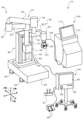
- FIG. 1 is an external perspective view of an ultrasonic diagnostic system including a robot device of this embodiment.
- FIG. 2 is a side view of the robot device.
- FIG. 2 is a block diagram showing an electrical connection relationship between a robot device and an ultrasonic diagnostic device.
- FIG. 3 is an explanatory diagram showing a movement trajectory of an ultrasound probe.
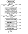
- 3 is a flowchart illustrating an example of collision determination processing. It is an explanatory diagram explaining a restricted area. It is a flowchart which shows an example of safety processing.
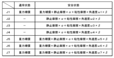
- FIG. 7 is an explanatory diagram showing compensation torques of the elevating axis J1 and each of the joint axes J2 to J7, which are set respectively in a normal state and a safe state.
- FIG. 1 is an external perspective view of an ultrasound diagnostic system 10 including a robot device 20 of this embodiment.
- FIG. 2 is a side view of the robot device 20.
- FIG. 3 is a block diagram showing the electrical connection relationship between the robot device 20 and the ultrasound diagnostic device 100.
- the left-right direction is the X-axis direction
- the front-back direction is the Y-axis direction
- the up-down direction is the Z-axis direction.
- the ultrasonic diagnostic system 10 of this embodiment holds an ultrasonic probe 101 at the tip of a robot arm 21, and operates the robot device 20 so that the ultrasonic probe 101 is pressed against the patient's body surface. Obtain an echo image.
- This ultrasonic diagnostic system 10 is used for catheter treatment, for example.
- the operator (operator) who operates the guide wire of the catheter presses the ultrasound probe 101 against the surface of the patient's thigh and recognizes the positional relationship between the tip of the guide wire and the blood vessel from the obtained ultrasound echo image.
- the ultrasound diagnostic system 10 of this embodiment includes a robot device 20, a console device 90, and an ultrasound diagnostic device 100, as shown in FIGS. 1 to 3.
- the ultrasound diagnostic device 100 includes an ultrasound probe 101 and an ultrasound diagnostic device main body 110 connected to the ultrasound probe 101 via a cable 102.
- the ultrasound diagnostic device main body 110 includes an ultrasound diagnostic control unit 111 that controls the entire device, and an image processing unit that processes received signals from the ultrasound probe 101 to generate ultrasound echo images. 112, an image display section 113 that displays an ultrasound echo image, and various operation switches (not shown).
- the console device 90 is provided separately from the robot device 20 and is used to instruct various operations of the robot device 20 and display various information including the status of the robot device 20.
- the console device 90 includes a console control section 91 that controls the entire device, an operation panel 92 that displays various information and can be touch-operated by an operator, a speaker 93, and a communication section 94 that communicates with the robot device 20.
- An emergency stop switch 95 is provided.
- the emergency stop switch 95 is a switch for stopping the operation of the robot device 20 in an emergency.
- the console device 90 is connected to a foot pedal 96 and a joint controller 97 via a cable.
- the foot pedal 96 and the joint controller 97 are operating members that can give various instructions.
- the robot device 20 includes a base 25, a robot arm 21 installed on the base 25, and a height adjustment mechanism 45 that adjusts the height of the robot arm 21 by manual operation. and a robot control device 80 (see FIG. 3) that controls the robot arm 21.
- Casters 26 with stoppers are attached to the four corners of the back surface of the base 25, as shown in FIGS. 1 and 2.
- the robot device 20 can be freely moved by casters 26.
- locking portions 28 are provided at multiple locations (for example, three locations) on the back surface of the base 25 to protrude vertically downward by pressing down on the lever 27 to lock (fix) the robot device 20 immovably. .
- the robot arm 21, as shown in FIG. has.
- the base end of the first arm 22 is connected to the base 24 via a first joint shaft 31 (hereinafter sometimes referred to as "joint shaft J2") that extends in the vertical direction (Z-axis direction).
- the first arm drive device 35 includes a motor 35a, an encoder 35b, and an amplifier 35c.
- the rotating shaft of the motor 35a is connected to the first joint shaft 31 via a reduction gear (not shown).
- the first arm driving device 35 rotates (swivels) the first arm 22 along a horizontal plane (XY plane) using the first joint axis 31 as a fulcrum by rotationally driving the first joint axis 31 with a motor 35a.
- the encoder 35b is attached to the rotating shaft of the motor 35a, and is configured as a rotary encoder that detects the amount of rotational displacement of the motor 35a.
- the amplifier 35c is a drive unit for driving the motor 35a by switching a switching element.
- the base end of the second arm 23 is connected to the distal end of the first arm 22 via a second joint shaft 32 (hereinafter sometimes referred to as "joint shaft J3") that extends in the vertical direction.
- the second arm drive device 36 includes a motor 36a, an encoder 36b, and an amplifier 36c.
- the rotating shaft of the motor 36a is connected to the second joint shaft 32 via a speed reducer (not shown).
- the second arm driving device 36 rotates (swivels) the second arm 23 along a horizontal plane using the second joint shaft 32 as a fulcrum by rotationally driving the second joint shaft 32 with a motor 36a.
- the encoder 36b is attached to the rotating shaft of the motor 36a, and is configured as a rotary encoder that detects the amount of rotational displacement of the motor 36a.
- the amplifier 36c is a drive section for driving the motor 35a by switching a switching element.
- the base 24 is provided so as to be movable up and down relative to the base 25 by a lifting device 40 installed on the base 25.
- the elevating device 40 includes a first slider 41 fixed to the base 24, a first guide member 42 that extends in the vertical direction and guides the movement of the first slider 41, and A first ball screw shaft 43 (hereinafter sometimes referred to as "elevating shaft J1") that extends in the direction and is screwed with a ball screw nut (not shown) fixed to the first slider 41;
- the motor 44a includes a motor 44a that rotationally drives a ball screw shaft 43, an encoder 44b (see FIG. 3), and an amplifier 44c that drives the motor 44a.
- the lifting device 40 moves the base 24 fixed to the first slider 41 up and down along the first guide member 42 by rotationally driving the first ball screw shaft 43 by the motor 44a. Therefore, the robot arm 21 moves up and down along the lifting axis J1.
- the encoder 44b is configured as a linear encoder that detects the vertical position (elevating position) of the first slider 41 (base 24).
- the height adjustment mechanism 45 includes a second slider 46 fixed to the first guide member 42 of the lifting device 40, and a second slider 46 fixed to the base 25 and extending in the vertical direction.
- a second guide member 47 that guides the movement of the second slider 46 and a second ball screw shaft 48 (elevating shaft) that extends in the vertical direction and is screwed with a ball screw nut (not shown) fixed to the second slider ) and an operation handle 49 connected to the second ball screw shaft 48 via a power transmission mechanism (bevel gear).
- the height adjustment mechanism 45 rotates the second ball screw shaft 48 by manually operating the operating handle 49, thereby moving the first guide member 42 of the lifting device 40 fixed to the second slider 46 to the second guide member 47. Move up and down along.
- the base end of the robot arm 21 is fixed to the base 24, and the base 24 is supported by the first guide member 42, so by moving the first guide member 42 up and down by the height adjustment mechanism 45, The height of the robot arm 21 can be adjusted. Thereby, for example, the height of the robot arm 21 can be adjusted according to the height of the bed on which the subject (patient) for ultrasound diagnosis lies.
- the three-axis rotating mechanism 50 rotates the second arm 23 via a posture maintaining shaft 33 (hereinafter sometimes referred to as "joint axis J4") that extends in the vertical direction. Connected to the tip.
- the three-axis rotating mechanism 50 includes a first rotating shaft 51 (hereinafter sometimes referred to as “joint axis J5"), a second rotating shaft 52 (hereinafter sometimes referred to as “joint axis J6”), and A third rotating shaft 53 (hereinafter sometimes referred to as "joint axis J7”), a first rotating device 55 that rotates the first rotating shaft 51, and a second rotating device 56 that rotates the second rotating shaft 52.
- the first rotating shaft 51 is supported in a position orthogonal to the position maintaining shaft 33.
- the second rotating shaft 52 is supported in a position perpendicular to the first rotating shaft 51 .
- the third rotating shaft 53 is supported in a position orthogonal to the second rotating shaft 52.
- the first rotating device 55 includes a motor 55a that rotationally drives the first rotating shaft 51, an encoder 55b that is attached to the rotating shaft of the motor 55a and detects the amount of rotational displacement of the motor 55a, and an amplifier 55c that drives the motor 55a. has.
- the second rotating device 56 includes a motor 56a that rotationally drives the second rotating shaft 52, an encoder 56b that is attached to the rotating shaft of the motor 56a and detects the amount of rotational displacement of the motor 56a, and an amplifier 56c that drives the motor 56a. has.
- the third rotating device 57 includes a motor 57a that rotationally drives the third rotating shaft 53, an encoder 57b that is attached to the rotating shaft of the motor 57a and detects the amount of rotational displacement of the motor 57a, and an amplifier 57c that drives the motor 56a. has. Further, the third rotating shaft 53 is provided with a holding section 60 for holding the ultrasound probe 101.
- the holding unit 60 holds the ultrasound probe 101 so as to be coaxial with the third rotating shaft 53.
- the holding part 60 has a teaching mode, which will be described later, in which a worker manually operates the ultrasonic probe 101 while holding the ultrasonic probe 101 at the tip (holding part 60) of the robot arm 21.
- a switch 62 is provided to permit manual operation. This may be used as a direct teaching enable switch 62 to add a function to stop the robot arm 21 in an emergency.
- the robot device 20 of the present embodiment can perform translational motion in three directions, that is, the X-axis direction, the Y-axis direction, and the Z-axis direction, by the first arm drive device 35, the second arm drive device 36, and the lifting device 40, and three rotational axes.
- the ultrasound probe 101 can be moved to any position in any posture within the movable area. can be moved to.
- the posture holding device 37 maintains the posture of the rotating three-axis mechanism 50 (orientation of the first rotating shaft 51) in a constant direction regardless of the postures of the first arm 22 and the second arm 23.
- the posture holding device 37 includes a motor 37a, an encoder 37b, and an amplifier 37c.
- the rotating shaft of the motor 37a is connected to the posture maintaining shaft 33 via a reduction gear (not shown).
- the posture maintaining device 37 maintains the posture based on the rotation angle of the first joint shaft 31 and the rotation angle of the second joint shaft 32 so that the axial direction of the first rotation shaft 51 is always in the left-right direction (X-axis direction).
- a target rotation angle of the holding shaft 33 is set, and the motor 37a is drive-controlled so that the posture holding shaft 33 reaches the target rotation angle. This makes it possible to independently control translational motion in three directions and rotational motion in three directions, thereby facilitating control.
- the force sensor 61 is attached to the tip of the robot arm 21, and detects force components acting in the directions of the X, Y, and Z axes and torque components acting around each axis as external forces acting on the robot arm 21. Detect.
- the robot control device 80 includes a robot control section 81, a monitoring section 82, an IO section 83, a communication section 84, and a storage section 85.
- the robot control unit 81 is configured as a processor including a CPU, ROM, RAM, peripheral circuits, and the like.
- the monitoring unit 82 is configured as a one-chip microcomputer including a CPU, ROM, RAM, peripheral circuits, and the like. Furthermore, the monitoring section 82 may be duplicated.
- the robot control unit 81 performs various processes related to controlling the robot arm 21 (motors 35a to 37a, 44a, 55a to 57a).
- the monitoring unit 82 monitors the status of each unit such as the IO unit 83, the communication unit 84, the amplifiers 35c to 37c, 44c, 55c to 57c, and the sensor unit including the encoders 35b to 37b, 44b, 55b to 57b, etc.
- the IO section 83 is an I/O port, and inputs a detection signal from the direct teaching enable switch 62 and inputs/outputs a signal from an external device.
- the communication unit 84 communicates with the robot control device 80 and the console device 90 by wire or wirelessly, and exchanges various control signals and data with each other.
- the amplifiers 35c to 37c, 44c, and 55c to 57c each include a motor control section 71, a drive power supply section 72, and an IO section 73.
- the motor control unit 71 has switching elements, and controls each motor 35a to 37a, 44a, 55a to 57a by controlling the switching elements based on feedback signals from encoders 35b to 37b, 44b, 55b to 57b, etc. control.
- the drive power supply section 72 supplies the power necessary to drive the motors 35a to 37a, 44a, and 55a to 57a.
- the IO section 83 is an I/O port, and receives position signals from the encoders 35b to 37b, 44b, and 55b to 57b, and current signals from current sensors that detect the current flowing through each motor 35a to 37a, 44a, and 55a to 57a. , various signals such as command signals (control signals) are input from the robot control unit 81 to the respective motors 35a to 37a, 44a, and 55a to 57a.
- the robot device 20 included in the ultrasonic diagnostic system 10 configured in this way has a direct teaching mode and an automatic operation mode as operating modes.
- the position and orientation of the ultrasound probe 101 are registered at multiple arbitrary points while the operator grasps the tip (holding part 60) of the robot arm 21 that holds the ultrasound probe 101 and manually operates it.
- the robot control unit 81 controls the vertical position Z1 of the vertical axis J1 and the vertical position of the joint axis J2 to J7 from each encoder 35b to 37b, 44b, 55b to 57b based on registration instructions from the operator. Obtain rotation angles ⁇ 2 to ⁇ 7.
- the robot control unit 81 determines the position and posture of the hand of the robot arm 21 using forward kinematics, that is, the ultrasonic The position and orientation of the probe 101 are calculated.
- the robot control unit 81 associates the acquired elevation position Z1 and rotation angles ⁇ 2 to ⁇ 7 with the calculated position and orientation of the ultrasound probe 101 and stores them in the storage unit 85 as registration points.
- the operator's registration instruction can be given by, for example, pressing the foot pedal 96, operating the operation panel 92, or using voice recognition.
- a movable area is defined for the robot device 20.
- each motor 35a is moved so that a load (resistance) is applied in the opposite direction to the direction in which the robot arm 21 is operated by the operator. ⁇ 37a, 44a, 55a ⁇ 57a.
- the operating direction of the robot arm 21 can be determined based on detection signals from the force sensor 61 and detection signals from the encoders 35b to 37b, 44b, and 55b to 57b.
- the automatic operation mode is a mode in which the robot device 20 automatically moves the ultrasound probe 101 so as to pass through a plurality of points registered in the direct teaching mode in a predetermined order.
- the robot controller 81 moves the ultrasound probe 101 to the first point among a plurality of points registered in advance.
- the movement of the ultrasonic probe 101 is performed by adjusting the lifting position of the lifting axis J1 and the rotation angle of the joint axes J2 to J7 of the robot arm 21 corresponding to the point to be moved (the position and posture of the hand of the robot arm 21) to the target lifting position Z1tag and the rotation angle of the joint axes J2 to J7.
- the target vertical position corresponding to the vertical position Z1 of the vertical axis J1 and the rotation angle ⁇ 2 to ⁇ 7 of the joint axes J2 to J7 which are set to the target rotation angles ⁇ 2tag to ⁇ 7tag and detected by each encoder 35b to 37b, 44b, 55b to 57b. This is done by controlling each of the motors 35a to 37a, 44a, and 55a to 57a to match Z1tag and target rotation angles ⁇ 2tag to ⁇ 7tag.
- the robot control unit 81 moves the ultrasonic probe 101 to the next point when the operator performs a forward operation. On the other hand, when the operator performs a return operation, the robot control unit 81 moves the ultrasound probe 101 to the previous point.
- the forward operation and return operation can be performed by, for example, depressing the foot pedal 96, operating the operation panel 92, or operating by voice recognition.
- the points (trajectory of movement) registered in the direct teaching mode are displayed in three dimensions on the operation panel 92 of the console device 90, as shown in FIG.
- the operator can confirm in advance the destination of the ultrasonic probe 101 using the operation panel 92.
- the robot device 20 of this embodiment determines whether or not there is a collision between the robot arm 21 (including the ultrasonic probe 101) and another object, and if it is determined that there has been a collision with another object, the robot arm 21 is moved away from the object. We are planning to move to a safe state where we will evacuate the area.
- FIG. 5 is a flowchart showing an example of a collision determination process executed by the robot control unit 81 of the robot control device 80. This process is repeatedly executed at predetermined time intervals (for example, every few milliseconds or tens of milliseconds).
- the robot control unit 81 When the collision determination process is executed, the robot control unit 81 first determines whether the current state of the robot device 20 is the normal state (S100). If the robot control unit 81 determines that the current state is not a normal state but a safe state, it ends the collision determination process. On the other hand, if the robot control unit 81 determines that the current state is the normal state, the robot control unit 81 determines the vertical position Z1 of the vertical axis J1 and the rotation angle ⁇ 2 of the joint axes J2 to J7 from each encoder 35b to 37b, 44b, 55b to 57b.
- the robot control unit 81 determines whether the vertical position Z1 is larger than the threshold Z1ref and whether the angular velocities ⁇ 2 to ⁇ 7 are larger than the corresponding thresholds ⁇ 2ref to ⁇ 7ref (S130).
- the thresholds Z1ref, ⁇ 2ref to ⁇ 7ref are thresholds for determining whether the displacement of the robot arm 21 is caused by a collision with another object, and usually the vertical axis when operating the robot arm 21 is The speed is set to be slightly higher than the upper limit of the speed range of the vertical speed of J1 and the angular speed of joint axes J2 to J7. If the robot control unit 81 determines that the vertical speed V1 is equal to or lower than the threshold value V1ref and any of the angular velocities ⁇ 2 to ⁇ 7 are equal to or lower than the corresponding thresholds ⁇ 2ref to ⁇ 7ref, the robot control unit 81 determines that no collision with another object has occurred. The collision determination process ends.
- the robot control unit 81 determines that the vertical speed V1 is greater than the threshold value V1ref, or if it determines that any of the angular velocities ⁇ 2 to ⁇ 7 is greater than the corresponding threshold values ⁇ 2ref to ⁇ 7ref, it determines that the robot has collided with another object. (S140). Next, the robot control unit 81 uses forward kinematics to determine the hand position P of the robot arm 21 (ultrasonic probe 101 position) is calculated (S150), and the restricted area is updated based on the calculated hand position P (S160). Then, the robot control unit 81 shifts to a safe state (S170) and ends the collision determination process.
- the restricted area is an area in the movable area where the movement of the robot arm 21 is restricted.
- the restriction area is an initial area, which is the assumed maximum radius of the thigh (assumed maximum It is set in a circular (fan-shaped) area surrounded by the thigh radius).
- the restricted area is defined as the distance between the hand position P (position of the ultrasound probe 101) and the predetermined position O at the time of the collision with a radius ( The area is updated (changed) to a circular (fan-shaped) area with the collision position radius).
- the shape of the restricted area is not limited to a circular (fan-shaped) shape in a cross-sectional view of the thigh, but may be an ellipse, an egg shape, or the like. Further, the restricted area may be set to have a cylindrical shape or a tapered shape in the depth direction in FIG. 6 . The operation of the robot device 20 when the tip of the robot arm 21 (ultrasonic probe 101) enters the restricted area in the safe state will be described later.
- FIG. 7 is a flowchart showing an example of safety processing executed by the robot control unit 81. This process is repeatedly executed at predetermined time intervals (for example, every several milliseconds or tens of milliseconds) from the transition to the safe state until the end of the safe state.
- the robot control unit 81 When the safety process is executed, the robot control unit 81 first inputs the elevation position Z1 of the elevation axis J1 and the rotation angles ⁇ 2 to ⁇ 7 of the joint axes J2 to J7 from the encoders 35b to 37b, 44b, and 55b to 57b ( S200), the hand position P, the retraction distance L, and the retraction speed V are calculated (S210).
- the calculation of the hand position P has been described above.
- the evacuation distance L is the cumulative amount of movement of the hand position P after transitioning to the safe state, and can be calculated by integrating the distance between the hand position P calculated this time and the hand position calculated last time. .
- the retreat speed V can be calculated by dividing the distance between the currently calculated hand position P and the previously calculated hand position by the safety process execution time interval.
- the robot control unit 81 determines whether the hand position P is within the restricted area (S220), whether the evacuation distance L exceeds the threshold Lref (S230), and whether the evacuation speed V exceeds the threshold Vref. (S240) and whether a predetermined time has elapsed since transition to the safe state (S250).
- the robot control unit 81 determines that the hand position P is not within the restricted area, the evacuation distance L is less than or equal to the threshold value Lref, the evacuation speed V is less than or equal to the threshold value Vref, and a predetermined period of time has elapsed since the transition to the safe state.
- the robot control unit 81 sets a compensation torque Tc1 for the vertical axis J1 based on the calculated vertical speed V1, and also sets a compensation torque Tc2 to Tc7 for the joint axes J2 to J7 based on the calculated angular velocities ⁇ 2 to ⁇ 7. (S270).
- the robot control unit 81 sets the torque that is the original torque that should be output to the lifting axis Z1 and the compensation torque Tc1 added to it as the torque command for the lifting axis Z1, and also sets the torque that is the original torque that should be output to the lifting axis Z1 to the original torque that should be output to each of the joint axes J2 to J7.
- the torque obtained by adding each compensation torque Tc2 to Tc7 to the torque is set as the torque command for the joint axes J2 to J7 (S280).
- the robot control unit 81 controls each motor 35a to 37a, 44a, and 55a to 57a so that a torque corresponding to the set torque command is output (S290), and ends the safety process.
- FIG. 8 is an explanatory diagram showing compensation torques of the elevating axis J1 and each of the joint axes J2 to J7, which are set respectively in the normal state and the safe state.
- the compensation torques Tc1 to Tc7 include a compensation torque for static friction (static friction compensation) and a compensation torque for viscous friction (viscous friction compensation).
- the above-mentioned torque corresponding to the vertical speed V1 and the angular velocities ⁇ 2 to ⁇ 7 is added to the viscous friction compensation term.
- the compensation torques of the lifting axis J1 and the joint axes J5 to J7 include a compensation torque (gravity compensation) in a direction that cancels out the load torque due to the body's own weight in both the normal state and the safe state. Since the joint axes J2 to J4 extend vertically in the axial direction, gravity compensation is not necessary.
- the robot device 20 can evacuate the robot arm 21 that collided with the object (worker) in a direction away from the object.
- the pressing force of the robot arm 21 can be quickly relaxed, and the safety of the worker can be sufficiently ensured.
- the retracting operation of the robot arm 21 is executed by a torque corresponding to an external force acting on the robot arm 21. Therefore, if the external force is no longer applied to the robot arm 21, the torque corresponding to the external force will not be output. This allows the robot device 20 to retreat the robot arm 21 by the amount necessary to alleviate the pushing force, thereby suppressing the occurrence of secondary damage such as collision with another object during the retreat operation, for example. be able to.
- the robot control unit 81 determines that the hand position P is within the restricted area in S220, determines that the retraction distance L exceeds the threshold value Lref in S230, or determines that the retraction speed V exceeds the threshold value Vref in S240. If it is determined that there is, or that a predetermined time has elapsed since the transition to the safe state in S250, the safe state is ended (S300) and the safety process is ended. Specifically, the robot control unit 81 controls each motor 35a to 37a, 44a, and 55a to 57a so that the retracting operation of the robot arm 21 is stopped. Thereby, it is possible to avoid an unexpected movement in the retracting operation of the robot arm 21, and to suppress the occurrence of secondary damage.
- the robot arm 21 of this embodiment corresponds to the robot main body
- the motors 35a to 37a, 44a, and 55a to 57a correspond to the drive section
- the encoders 35b to 37b, 44b, and 55b to 57b correspond to the external force detection section
- the robot control section 81 corresponds to the control section.
- the encoders 35b to 37b, 44b, and 55b to 57b also correspond to the position detection section.
- the ultrasonic probe 101 corresponds to an ultrasonic probe.
- the robot device 20 determines whether the vertical speed V1 of the vertical axis J1 and the angular velocities ⁇ 2 to ⁇ 7 of the joint axes J2 to J7 are larger than the corresponding thresholds Z1ref, ⁇ 2ref to ⁇ 7ref.
- the external force acting on the robot arm 21 due to a collision with another object is detected.
- the robot device 20 detects the external force acting on the robot arm 21 due to a collision with another object by detecting the torque acting on the lifting axis J1 and the joint axes J2 to J7 using a torque sensor. It's okay.
- the robot control unit 81 may set a compensation torque corresponding to (proportional to) the detected torque in the direction of the detected torque. Further, the robot device 20 may directly detect the external force acting on the robot arm 21 using the force sensor 61. In this case, as the external force acting on the robot arm 21, the force sensor 61 detects force components acting in the directions of the X, Y, and Z axes, and torque components acting around each axis. Therefore, the robot control unit 81 uses a conversion matrix to convert the force component and torque component detected by the force sensor 61 into the torque of the vertical axis J1 and each joint axis J2 to J7, and sets the compensation torque. good.
- the robot control unit 81 sets the robot arm 21 in the direction of the external force acting on the robot arm 21 due to the collision with another object (the direction of the vertical speed V1 and the angular velocities ⁇ 2 to ⁇ 7) as the retraction direction.
- the motors 35a to 37a, 44a, and 55a to 57a are controlled so that the motor 21 is retracted.
- the robot control unit 81 sets the direction of the retracting motion of the robot arm 21 to be opposite to the direction of the motion of the robot arm 21 at the time of the collision (the vertical direction of the vertical axis J1, the rotational direction of the joint axes J2 to J7). You may.
- the robot device 20 is configured as a seven-axis articulated robot capable of translational movement in three directions and rotational movement in three directions.
- the number of axes may be any number.
- the robot device 20 may be configured by a so-called vertically articulated robot, horizontally articulated robot, or the like.
- the robot device of the present disclosure controls the drive unit so that the robot body moves in a predetermined direction when an external force acting on the robot body due to contact with an object is detected.
- the pushing force of the robot body can be alleviated, and the safety of workers and the like can be further improved.
- control unit may control the drive unit so that, as the safe state, the larger the detected external force is, the larger the driving force is used to cause the robot main body to retreat. In this way, when the robot body collides with another object (worker), the pushing force of the robot body can be reduced by the necessary amount, and the safety of the worker etc. can be further improved.
- control unit may control the drive unit so that the robot main body performs a retracting operation in the direction of the detected external force as the safe state. In this way, the retraction direction of the robot body can be appropriately determined through simple processing.
- the robot device of the present disclosure includes a position detection unit that detects the position of the robot body, the robot body is a robot body of a medical robot used for diagnosis and treatment of patients, and the control unit includes: The robot controls the drive unit so that the robot body operates based on the assumed thigh position of the patient, and the robot body is detected by the position detection unit when an external force acting on the robot body is detected.
- the thigh position may be changed based on the position of the main body. In this way, when working on a patient's thigh, it is possible to appropriately grasp the position of the thigh, which varies from person to person.
- the control unit may terminate the retreating operation when the robot main body enters a restricted area set within a movable area due to the retreating operation in the safe state. .
- the controller includes a position detection unit that detects the position of the robot body, and the control unit controls the robot body detected by the position detection unit when an external force acting on the robot body is detected by the external force detection unit.
- a predetermined range with the position of the main body as a boundary may be set as the restricted area. In this way, the restriction area can be set appropriately.
- control unit may control, when a predetermined period of time has elapsed since the transition to the safe state, and when the amount of movement of the robot main body in the evacuation operation exceeds a predetermined amount in the safe state;
- the evacuation operation may be terminated when the moving speed of the robot main body during the evacuation operation exceeds a predetermined speed in the safe state. In this way, it is possible to avoid unexpected operations during the evacuation operation and to suppress the occurrence of secondary damage.
- the robot main body has an arm
- the drive section has a motor that drives a joint shaft of the arm
- the external force detection section is configured to detect an external force acting on the robot main body. detects the angular velocity of the joint shaft or the torque acting on the joint shaft, and the control unit, in the safe state, applies an additional torque corresponding to the detected angular velocity or torque to the detected angular velocity from the corresponding motor.
- the drive unit may be controlled so that the torque is output in the direction of torque. In this way, the evacuation operation can be performed appropriately.
- the robot main body includes an arm
- the drive unit includes a motor that drives a joint shaft of the arm
- the external force detection unit detects a force provided on the arm.
- the control unit controls the drive unit so that, in the safe state, an additional torque corresponding to the detected value of the force sensor is output from the corresponding motor in the direction of the detected external force. You may. In this way, the evacuation operation can be performed appropriately.
- the present disclosure is not limited to the form of a robot device, but can also be applied to an ultrasonic diagnostic system.
- the present disclosure can be used in the manufacturing industry of robotic devices and ultrasonic diagnostic systems.
Landscapes
- Engineering & Computer Science (AREA)
- Health & Medical Sciences (AREA)
- Life Sciences & Earth Sciences (AREA)
- Medical Informatics (AREA)
- Surgery (AREA)
- Pathology (AREA)
- Radiology & Medical Imaging (AREA)
- Biophysics (AREA)
- Biomedical Technology (AREA)
- Heart & Thoracic Surgery (AREA)
- Physics & Mathematics (AREA)
- Molecular Biology (AREA)
- Nuclear Medicine, Radiotherapy & Molecular Imaging (AREA)
- Animal Behavior & Ethology (AREA)
- General Health & Medical Sciences (AREA)
- Public Health (AREA)
- Veterinary Medicine (AREA)
- Robotics (AREA)
- Mechanical Engineering (AREA)
- Manipulator (AREA)
Priority Applications (2)
| Application Number | Priority Date | Filing Date | Title |
|---|---|---|---|
| PCT/JP2022/017321 WO2023195146A1 (ja) | 2022-04-08 | 2022-04-08 | ロボット装置および超音波診断システム |
| JP2024513657A JPWO2023195146A1 (https=) | 2022-04-08 | 2022-04-08 |
Applications Claiming Priority (1)
| Application Number | Priority Date | Filing Date | Title |
|---|---|---|---|
| PCT/JP2022/017321 WO2023195146A1 (ja) | 2022-04-08 | 2022-04-08 | ロボット装置および超音波診断システム |
Publications (1)
| Publication Number | Publication Date |
|---|---|
| WO2023195146A1 true WO2023195146A1 (ja) | 2023-10-12 |
Family
ID=88242825
Family Applications (1)
| Application Number | Title | Priority Date | Filing Date |
|---|---|---|---|
| PCT/JP2022/017321 Ceased WO2023195146A1 (ja) | 2022-04-08 | 2022-04-08 | ロボット装置および超音波診断システム |
Country Status (2)
| Country | Link |
|---|---|
| JP (1) | JPWO2023195146A1 (https=) |
| WO (1) | WO2023195146A1 (https=) |
Cited By (1)
| Publication number | Priority date | Publication date | Assignee | Title |
|---|---|---|---|---|
| WO2025191652A1 (ja) * | 2024-03-11 | 2025-09-18 | 株式会社Fuji | ロボットシステム、ロボット、及びロボットシステムの制御方法 |
Citations (5)
| Publication number | Priority date | Publication date | Assignee | Title |
|---|---|---|---|---|
| JP2005100143A (ja) * | 2003-09-25 | 2005-04-14 | Kobe Steel Ltd | モータ駆動装置の制御方法及び制御装置 |
| JP2015217451A (ja) * | 2014-05-14 | 2015-12-07 | ファナック株式会社 | 外力監視機能を有するワーク搬送方法システム |
| JP2018094639A (ja) * | 2016-12-08 | 2018-06-21 | ファナック株式会社 | ロボットシステム |
| JP2020192652A (ja) * | 2019-05-29 | 2020-12-03 | ファナック株式会社 | ロボットシステム |
| WO2021111581A1 (ja) * | 2019-12-05 | 2021-06-10 | 株式会社Fuji | 超音波診断システム |
-
2022
- 2022-04-08 JP JP2024513657A patent/JPWO2023195146A1/ja active Pending
- 2022-04-08 WO PCT/JP2022/017321 patent/WO2023195146A1/ja not_active Ceased
Patent Citations (5)
| Publication number | Priority date | Publication date | Assignee | Title |
|---|---|---|---|---|
| JP2005100143A (ja) * | 2003-09-25 | 2005-04-14 | Kobe Steel Ltd | モータ駆動装置の制御方法及び制御装置 |
| JP2015217451A (ja) * | 2014-05-14 | 2015-12-07 | ファナック株式会社 | 外力監視機能を有するワーク搬送方法システム |
| JP2018094639A (ja) * | 2016-12-08 | 2018-06-21 | ファナック株式会社 | ロボットシステム |
| JP2020192652A (ja) * | 2019-05-29 | 2020-12-03 | ファナック株式会社 | ロボットシステム |
| WO2021111581A1 (ja) * | 2019-12-05 | 2021-06-10 | 株式会社Fuji | 超音波診断システム |
Cited By (1)
| Publication number | Priority date | Publication date | Assignee | Title |
|---|---|---|---|---|
| WO2025191652A1 (ja) * | 2024-03-11 | 2025-09-18 | 株式会社Fuji | ロボットシステム、ロボット、及びロボットシステムの制御方法 |
Also Published As
| Publication number | Publication date |
|---|---|
| JPWO2023195146A1 (https=) | 2023-10-12 |
Similar Documents
| Publication | Publication Date | Title |
|---|---|---|
| US10300597B2 (en) | Robot and method of operating robot | |
| US6313595B2 (en) | Method of controlling an intelligent assist device in a plurality of distinct workspaces | |
| US10154822B2 (en) | Patient positioner system | |
| KR100483660B1 (ko) | 로봇 | |
| US9821459B2 (en) | Multi-joint robot having function for repositioning arm | |
| US6204620B1 (en) | Method of controlling an intelligent assist device | |
| US6738691B1 (en) | Control handle for intelligent assist devices | |
| US6612449B1 (en) | Intelligent power assisted manual manipulator | |
| US11668375B2 (en) | Parallel link mechanism and link actuation device | |
| WO2017094240A1 (ja) | ロボットシステムの監視装置 | |
| JP7826051B2 (ja) | ロボットの衝突検出方法及びロボットの衝突検出装置 | |
| CN209092068U (zh) | 一种上肢综合评估与康复训练机器人 | |
| JP6271835B2 (ja) | ロボットのハンドガイドシステム | |
| WO2023248327A1 (ja) | ロボット装置およびダイレクトティーチングのアシスト方法 | |
| WO2023195146A1 (ja) | ロボット装置および超音波診断システム | |
| JP7808107B2 (ja) | ロボットおよびアームの制御方法 | |
| CN112638600A (zh) | 机器人的控制装置 | |
| JP7605961B2 (ja) | 超音波診断システム | |
| WO2022153478A1 (ja) | 力覚センサ、協働ロボット及びロボット | |
| WO2023062737A1 (ja) | 超音波診断システムおよびその監視方法 | |
| JP7223608B2 (ja) | 作業用台車並びに作業用台車の制御装置および方法 | |
| US20210188600A1 (en) | System for operating a load-handling crane, and load-handling crane and method for operating same | |
| JPH11198067A (ja) | 双腕型マニピュレータ操縦装置 | |
| JP7285668B2 (ja) | ロボット及びそのブレーキ制御プログラム | |
| WO2024089813A1 (ja) | ロボット |
Legal Events
| Date | Code | Title | Description |
|---|---|---|---|
| 121 | Ep: the epo has been informed by wipo that ep was designated in this application |
Ref document number: 22936544 Country of ref document: EP Kind code of ref document: A1 |
|
| WWE | Wipo information: entry into national phase |
Ref document number: 2024513657 Country of ref document: JP |
|
| NENP | Non-entry into the national phase |
Ref country code: DE |
|
| 122 | Ep: pct application non-entry in european phase |
Ref document number: 22936544 Country of ref document: EP Kind code of ref document: A1 |