WO2023195146A1 - Robot device and ultrasound diagnostic system - Google Patents
Robot device and ultrasound diagnostic system Download PDFInfo
- Publication number
- WO2023195146A1 WO2023195146A1 PCT/JP2022/017321 JP2022017321W WO2023195146A1 WO 2023195146 A1 WO2023195146 A1 WO 2023195146A1 JP 2022017321 W JP2022017321 W JP 2022017321W WO 2023195146 A1 WO2023195146 A1 WO 2023195146A1
- Authority
- WO
- WIPO (PCT)
- Prior art keywords
- robot
- external force
- robot body
- control unit
- detected
- Prior art date
Links
- 238000002604 ultrasonography Methods 0.000 title description 37
- 230000007704 transition Effects 0.000 claims abstract description 7
- 239000000523 sample Substances 0.000 claims description 39
- 238000001514 detection method Methods 0.000 claims description 26
- 230000033001 locomotion Effects 0.000 claims description 18
- 210000000689 upper leg Anatomy 0.000 claims description 12
- 238000003745 diagnosis Methods 0.000 claims description 6
- 230000036544 posture Effects 0.000 description 14
- 238000000034 method Methods 0.000 description 13
- 238000012545 processing Methods 0.000 description 7
- 238000004891 communication Methods 0.000 description 6
- 238000010586 diagram Methods 0.000 description 6
- 238000006073 displacement reaction Methods 0.000 description 6
- 230000003028 elevating effect Effects 0.000 description 6
- 210000004204 blood vessel Anatomy 0.000 description 5
- 230000006378 damage Effects 0.000 description 5
- 238000012544 monitoring process Methods 0.000 description 5
- 238000003825 pressing Methods 0.000 description 4
- 238000006243 chemical reaction Methods 0.000 description 3
- 238000003860 storage Methods 0.000 description 3
- 230000005484 gravity Effects 0.000 description 2
- 238000012423 maintenance Methods 0.000 description 2
- 230000002093 peripheral effect Effects 0.000 description 2
- 230000003068 static effect Effects 0.000 description 2
- 238000013459 approach Methods 0.000 description 1
- 230000005540 biological transmission Effects 0.000 description 1
- 239000003638 chemical reducing agent Substances 0.000 description 1
- 230000001186 cumulative effect Effects 0.000 description 1
- 230000000881 depressing effect Effects 0.000 description 1
- 230000000694 effects Effects 0.000 description 1
- 238000004519 manufacturing process Methods 0.000 description 1
- 239000011159 matrix material Substances 0.000 description 1
- 238000005096 rolling process Methods 0.000 description 1
Images


Classifications
-
- A—HUMAN NECESSITIES
- A61—MEDICAL OR VETERINARY SCIENCE; HYGIENE
- A61B—DIAGNOSIS; SURGERY; IDENTIFICATION
- A61B8/00—Diagnosis using ultrasonic, sonic or infrasonic waves
- A61B8/12—Diagnosis using ultrasonic, sonic or infrasonic waves in body cavities or body tracts, e.g. by using catheters
-
- B—PERFORMING OPERATIONS; TRANSPORTING
- B25—HAND TOOLS; PORTABLE POWER-DRIVEN TOOLS; MANIPULATORS
- B25J—MANIPULATORS; CHAMBERS PROVIDED WITH MANIPULATION DEVICES
- B25J19/00—Accessories fitted to manipulators, e.g. for monitoring, for viewing; Safety devices combined with or specially adapted for use in connection with manipulators
- B25J19/06—Safety devices
Definitions
- This specification discloses a robotic device and an ultrasound diagnostic system.
- this type of robot device has a collision detection unit that detects when the robot has collided with an object, and a deceleration unit that drives each motor of the robot to decelerate when it is detected that the robot has collided with an object.
- a first control unit that executes control; and a second control unit that executes dynamic braking for a predetermined period of time after the deceleration control is executed, stopping power supply to each motor and short-circuiting power input and output terminals in each motor.
- a device comprising the following has been proposed (see, for example, Patent Document 1). With this robot device, when the robot collides with an object, the robot can be quickly decelerated, and injuries to workers can be suppressed. Additionally, the operator can push the robot to move or move away from the robot while dynamic braking is being performed.
- the main purpose of the present disclosure is to provide a robot device or an ultrasound diagnostic system equipped with a robot device that can further improve safety against collisions between a robot and an object.
- the present disclosure has taken the following measures to achieve the above-mentioned main objective.
- the robot device of the present disclosure includes: The robot body, a drive unit that drives the robot body; an external force detection unit that detects an external force acting on the robot body; a control unit that controls the drive unit to move to a safe state so that the robot body moves in a predetermined direction when an external force acting on the robot body is detected by the external force detection unit;
- the main point is to have the following.
- the robot device of the present disclosure controls the drive unit so that the robot body moves in a predetermined direction when an external force acting on the robot body due to contact with an object is detected.
- the ultrasound diagnostic system of the present disclosure includes an ultrasound probe and the robot device of the present disclosure that holds the ultrasound probe in its hand, it can achieve the same effects as the robot device of the present disclosure.
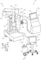
- FIG. 1 is an external perspective view of an ultrasonic diagnostic system including a robot device of this embodiment.
- FIG. 2 is a side view of the robot device.
- FIG. 2 is a block diagram showing an electrical connection relationship between a robot device and an ultrasonic diagnostic device.
- FIG. 3 is an explanatory diagram showing a movement trajectory of an ultrasound probe.
- 3 is a flowchart illustrating an example of collision determination processing. It is an explanatory diagram explaining a restricted area. It is a flowchart which shows an example of safety processing.
- FIG. 7 is an explanatory diagram showing compensation torques of the elevating axis J1 and each of the joint axes J2 to J7, which are set respectively in a normal state and a safe state.
- FIG. 1 is an external perspective view of an ultrasound diagnostic system 10 including a robot device 20 of this embodiment.
- FIG. 2 is a side view of the robot device 20.
- FIG. 3 is a block diagram showing the electrical connection relationship between the robot device 20 and the ultrasound diagnostic device 100.
- the left-right direction is the X-axis direction
- the front-back direction is the Y-axis direction
- the up-down direction is the Z-axis direction.
- the ultrasonic diagnostic system 10 of this embodiment holds an ultrasonic probe 101 at the tip of a robot arm 21, and operates the robot device 20 so that the ultrasonic probe 101 is pressed against the patient's body surface. Obtain an echo image.
- This ultrasonic diagnostic system 10 is used for catheter treatment, for example.
- the operator (operator) who operates the guide wire of the catheter presses the ultrasound probe 101 against the surface of the patient's thigh and recognizes the positional relationship between the tip of the guide wire and the blood vessel from the obtained ultrasound echo image.
- the ultrasound diagnostic system 10 of this embodiment includes a robot device 20, a console device 90, and an ultrasound diagnostic device 100, as shown in FIGS. 1 to 3.
- the ultrasound diagnostic device 100 includes an ultrasound probe 101 and an ultrasound diagnostic device main body 110 connected to the ultrasound probe 101 via a cable 102.
- the ultrasound diagnostic device main body 110 includes an ultrasound diagnostic control unit 111 that controls the entire device, and an image processing unit that processes received signals from the ultrasound probe 101 to generate ultrasound echo images. 112, an image display section 113 that displays an ultrasound echo image, and various operation switches (not shown).
- the console device 90 is provided separately from the robot device 20 and is used to instruct various operations of the robot device 20 and display various information including the status of the robot device 20.
- the console device 90 includes a console control section 91 that controls the entire device, an operation panel 92 that displays various information and can be touch-operated by an operator, a speaker 93, and a communication section 94 that communicates with the robot device 20.
- An emergency stop switch 95 is provided.
- the emergency stop switch 95 is a switch for stopping the operation of the robot device 20 in an emergency.
- the console device 90 is connected to a foot pedal 96 and a joint controller 97 via a cable.
- the foot pedal 96 and the joint controller 97 are operating members that can give various instructions.
- the robot device 20 includes a base 25, a robot arm 21 installed on the base 25, and a height adjustment mechanism 45 that adjusts the height of the robot arm 21 by manual operation. and a robot control device 80 (see FIG. 3) that controls the robot arm 21.
- Casters 26 with stoppers are attached to the four corners of the back surface of the base 25, as shown in FIGS. 1 and 2.
- the robot device 20 can be freely moved by casters 26.
- locking portions 28 are provided at multiple locations (for example, three locations) on the back surface of the base 25 to protrude vertically downward by pressing down on the lever 27 to lock (fix) the robot device 20 immovably. .
- the robot arm 21, as shown in FIG. has.
- the base end of the first arm 22 is connected to the base 24 via a first joint shaft 31 (hereinafter sometimes referred to as "joint shaft J2") that extends in the vertical direction (Z-axis direction).
- the first arm drive device 35 includes a motor 35a, an encoder 35b, and an amplifier 35c.
- the rotating shaft of the motor 35a is connected to the first joint shaft 31 via a reduction gear (not shown).
- the first arm driving device 35 rotates (swivels) the first arm 22 along a horizontal plane (XY plane) using the first joint axis 31 as a fulcrum by rotationally driving the first joint axis 31 with a motor 35a.
- the encoder 35b is attached to the rotating shaft of the motor 35a, and is configured as a rotary encoder that detects the amount of rotational displacement of the motor 35a.
- the amplifier 35c is a drive unit for driving the motor 35a by switching a switching element.
- the base end of the second arm 23 is connected to the distal end of the first arm 22 via a second joint shaft 32 (hereinafter sometimes referred to as "joint shaft J3") that extends in the vertical direction.
- the second arm drive device 36 includes a motor 36a, an encoder 36b, and an amplifier 36c.
- the rotating shaft of the motor 36a is connected to the second joint shaft 32 via a speed reducer (not shown).
- the second arm driving device 36 rotates (swivels) the second arm 23 along a horizontal plane using the second joint shaft 32 as a fulcrum by rotationally driving the second joint shaft 32 with a motor 36a.
- the encoder 36b is attached to the rotating shaft of the motor 36a, and is configured as a rotary encoder that detects the amount of rotational displacement of the motor 36a.
- the amplifier 36c is a drive section for driving the motor 35a by switching a switching element.
- the base 24 is provided so as to be movable up and down relative to the base 25 by a lifting device 40 installed on the base 25.
- the elevating device 40 includes a first slider 41 fixed to the base 24, a first guide member 42 that extends in the vertical direction and guides the movement of the first slider 41, and A first ball screw shaft 43 (hereinafter sometimes referred to as "elevating shaft J1") that extends in the direction and is screwed with a ball screw nut (not shown) fixed to the first slider 41;
- the motor 44a includes a motor 44a that rotationally drives a ball screw shaft 43, an encoder 44b (see FIG. 3), and an amplifier 44c that drives the motor 44a.
- the lifting device 40 moves the base 24 fixed to the first slider 41 up and down along the first guide member 42 by rotationally driving the first ball screw shaft 43 by the motor 44a. Therefore, the robot arm 21 moves up and down along the lifting axis J1.
- the encoder 44b is configured as a linear encoder that detects the vertical position (elevating position) of the first slider 41 (base 24).
- the height adjustment mechanism 45 includes a second slider 46 fixed to the first guide member 42 of the lifting device 40, and a second slider 46 fixed to the base 25 and extending in the vertical direction.
- a second guide member 47 that guides the movement of the second slider 46 and a second ball screw shaft 48 (elevating shaft) that extends in the vertical direction and is screwed with a ball screw nut (not shown) fixed to the second slider ) and an operation handle 49 connected to the second ball screw shaft 48 via a power transmission mechanism (bevel gear).
- the height adjustment mechanism 45 rotates the second ball screw shaft 48 by manually operating the operating handle 49, thereby moving the first guide member 42 of the lifting device 40 fixed to the second slider 46 to the second guide member 47. Move up and down along.
- the base end of the robot arm 21 is fixed to the base 24, and the base 24 is supported by the first guide member 42, so by moving the first guide member 42 up and down by the height adjustment mechanism 45, The height of the robot arm 21 can be adjusted. Thereby, for example, the height of the robot arm 21 can be adjusted according to the height of the bed on which the subject (patient) for ultrasound diagnosis lies.
- the three-axis rotating mechanism 50 rotates the second arm 23 via a posture maintaining shaft 33 (hereinafter sometimes referred to as "joint axis J4") that extends in the vertical direction. Connected to the tip.
- the three-axis rotating mechanism 50 includes a first rotating shaft 51 (hereinafter sometimes referred to as “joint axis J5"), a second rotating shaft 52 (hereinafter sometimes referred to as “joint axis J6”), and A third rotating shaft 53 (hereinafter sometimes referred to as "joint axis J7”), a first rotating device 55 that rotates the first rotating shaft 51, and a second rotating device 56 that rotates the second rotating shaft 52.
- the first rotating shaft 51 is supported in a position orthogonal to the position maintaining shaft 33.
- the second rotating shaft 52 is supported in a position perpendicular to the first rotating shaft 51 .
- the third rotating shaft 53 is supported in a position orthogonal to the second rotating shaft 52.
- the first rotating device 55 includes a motor 55a that rotationally drives the first rotating shaft 51, an encoder 55b that is attached to the rotating shaft of the motor 55a and detects the amount of rotational displacement of the motor 55a, and an amplifier 55c that drives the motor 55a. has.
- the second rotating device 56 includes a motor 56a that rotationally drives the second rotating shaft 52, an encoder 56b that is attached to the rotating shaft of the motor 56a and detects the amount of rotational displacement of the motor 56a, and an amplifier 56c that drives the motor 56a. has.
- the third rotating device 57 includes a motor 57a that rotationally drives the third rotating shaft 53, an encoder 57b that is attached to the rotating shaft of the motor 57a and detects the amount of rotational displacement of the motor 57a, and an amplifier 57c that drives the motor 56a. has. Further, the third rotating shaft 53 is provided with a holding section 60 for holding the ultrasound probe 101.
- the holding unit 60 holds the ultrasound probe 101 so as to be coaxial with the third rotating shaft 53.
- the holding part 60 has a teaching mode, which will be described later, in which a worker manually operates the ultrasonic probe 101 while holding the ultrasonic probe 101 at the tip (holding part 60) of the robot arm 21.
- a switch 62 is provided to permit manual operation. This may be used as a direct teaching enable switch 62 to add a function to stop the robot arm 21 in an emergency.
- the robot device 20 of the present embodiment can perform translational motion in three directions, that is, the X-axis direction, the Y-axis direction, and the Z-axis direction, by the first arm drive device 35, the second arm drive device 36, and the lifting device 40, and three rotational axes.
- the ultrasound probe 101 can be moved to any position in any posture within the movable area. can be moved to.
- the posture holding device 37 maintains the posture of the rotating three-axis mechanism 50 (orientation of the first rotating shaft 51) in a constant direction regardless of the postures of the first arm 22 and the second arm 23.
- the posture holding device 37 includes a motor 37a, an encoder 37b, and an amplifier 37c.
- the rotating shaft of the motor 37a is connected to the posture maintaining shaft 33 via a reduction gear (not shown).
- the posture maintaining device 37 maintains the posture based on the rotation angle of the first joint shaft 31 and the rotation angle of the second joint shaft 32 so that the axial direction of the first rotation shaft 51 is always in the left-right direction (X-axis direction).
- a target rotation angle of the holding shaft 33 is set, and the motor 37a is drive-controlled so that the posture holding shaft 33 reaches the target rotation angle. This makes it possible to independently control translational motion in three directions and rotational motion in three directions, thereby facilitating control.
- the force sensor 61 is attached to the tip of the robot arm 21, and detects force components acting in the directions of the X, Y, and Z axes and torque components acting around each axis as external forces acting on the robot arm 21. Detect.
- the robot control device 80 includes a robot control section 81, a monitoring section 82, an IO section 83, a communication section 84, and a storage section 85.
- the robot control unit 81 is configured as a processor including a CPU, ROM, RAM, peripheral circuits, and the like.
- the monitoring unit 82 is configured as a one-chip microcomputer including a CPU, ROM, RAM, peripheral circuits, and the like. Furthermore, the monitoring section 82 may be duplicated.
- the robot control unit 81 performs various processes related to controlling the robot arm 21 (motors 35a to 37a, 44a, 55a to 57a).
- the monitoring unit 82 monitors the status of each unit such as the IO unit 83, the communication unit 84, the amplifiers 35c to 37c, 44c, 55c to 57c, and the sensor unit including the encoders 35b to 37b, 44b, 55b to 57b, etc.
- the IO section 83 is an I/O port, and inputs a detection signal from the direct teaching enable switch 62 and inputs/outputs a signal from an external device.
- the communication unit 84 communicates with the robot control device 80 and the console device 90 by wire or wirelessly, and exchanges various control signals and data with each other.
- the amplifiers 35c to 37c, 44c, and 55c to 57c each include a motor control section 71, a drive power supply section 72, and an IO section 73.
- the motor control unit 71 has switching elements, and controls each motor 35a to 37a, 44a, 55a to 57a by controlling the switching elements based on feedback signals from encoders 35b to 37b, 44b, 55b to 57b, etc. control.
- the drive power supply section 72 supplies the power necessary to drive the motors 35a to 37a, 44a, and 55a to 57a.
- the IO section 83 is an I/O port, and receives position signals from the encoders 35b to 37b, 44b, and 55b to 57b, and current signals from current sensors that detect the current flowing through each motor 35a to 37a, 44a, and 55a to 57a. , various signals such as command signals (control signals) are input from the robot control unit 81 to the respective motors 35a to 37a, 44a, and 55a to 57a.
- the robot device 20 included in the ultrasonic diagnostic system 10 configured in this way has a direct teaching mode and an automatic operation mode as operating modes.
- the position and orientation of the ultrasound probe 101 are registered at multiple arbitrary points while the operator grasps the tip (holding part 60) of the robot arm 21 that holds the ultrasound probe 101 and manually operates it.
- the robot control unit 81 controls the vertical position Z1 of the vertical axis J1 and the vertical position of the joint axis J2 to J7 from each encoder 35b to 37b, 44b, 55b to 57b based on registration instructions from the operator. Obtain rotation angles ⁇ 2 to ⁇ 7.
- the robot control unit 81 determines the position and posture of the hand of the robot arm 21 using forward kinematics, that is, the ultrasonic The position and orientation of the probe 101 are calculated.
- the robot control unit 81 associates the acquired elevation position Z1 and rotation angles ⁇ 2 to ⁇ 7 with the calculated position and orientation of the ultrasound probe 101 and stores them in the storage unit 85 as registration points.
- the operator's registration instruction can be given by, for example, pressing the foot pedal 96, operating the operation panel 92, or using voice recognition.
- a movable area is defined for the robot device 20.
- each motor 35a is moved so that a load (resistance) is applied in the opposite direction to the direction in which the robot arm 21 is operated by the operator. ⁇ 37a, 44a, 55a ⁇ 57a.
- the operating direction of the robot arm 21 can be determined based on detection signals from the force sensor 61 and detection signals from the encoders 35b to 37b, 44b, and 55b to 57b.
- the automatic operation mode is a mode in which the robot device 20 automatically moves the ultrasound probe 101 so as to pass through a plurality of points registered in the direct teaching mode in a predetermined order.
- the robot controller 81 moves the ultrasound probe 101 to the first point among a plurality of points registered in advance.
- the movement of the ultrasonic probe 101 is performed by adjusting the lifting position of the lifting axis J1 and the rotation angle of the joint axes J2 to J7 of the robot arm 21 corresponding to the point to be moved (the position and posture of the hand of the robot arm 21) to the target lifting position Z1tag and the rotation angle of the joint axes J2 to J7.
- the target vertical position corresponding to the vertical position Z1 of the vertical axis J1 and the rotation angle ⁇ 2 to ⁇ 7 of the joint axes J2 to J7 which are set to the target rotation angles ⁇ 2tag to ⁇ 7tag and detected by each encoder 35b to 37b, 44b, 55b to 57b. This is done by controlling each of the motors 35a to 37a, 44a, and 55a to 57a to match Z1tag and target rotation angles ⁇ 2tag to ⁇ 7tag.
- the robot control unit 81 moves the ultrasonic probe 101 to the next point when the operator performs a forward operation. On the other hand, when the operator performs a return operation, the robot control unit 81 moves the ultrasound probe 101 to the previous point.
- the forward operation and return operation can be performed by, for example, depressing the foot pedal 96, operating the operation panel 92, or operating by voice recognition.
- the points (trajectory of movement) registered in the direct teaching mode are displayed in three dimensions on the operation panel 92 of the console device 90, as shown in FIG.
- the operator can confirm in advance the destination of the ultrasonic probe 101 using the operation panel 92.
- the robot device 20 of this embodiment determines whether or not there is a collision between the robot arm 21 (including the ultrasonic probe 101) and another object, and if it is determined that there has been a collision with another object, the robot arm 21 is moved away from the object. We are planning to move to a safe state where we will evacuate the area.
- FIG. 5 is a flowchart showing an example of a collision determination process executed by the robot control unit 81 of the robot control device 80. This process is repeatedly executed at predetermined time intervals (for example, every few milliseconds or tens of milliseconds).
- the robot control unit 81 When the collision determination process is executed, the robot control unit 81 first determines whether the current state of the robot device 20 is the normal state (S100). If the robot control unit 81 determines that the current state is not a normal state but a safe state, it ends the collision determination process. On the other hand, if the robot control unit 81 determines that the current state is the normal state, the robot control unit 81 determines the vertical position Z1 of the vertical axis J1 and the rotation angle ⁇ 2 of the joint axes J2 to J7 from each encoder 35b to 37b, 44b, 55b to 57b.
- the robot control unit 81 determines whether the vertical position Z1 is larger than the threshold Z1ref and whether the angular velocities ⁇ 2 to ⁇ 7 are larger than the corresponding thresholds ⁇ 2ref to ⁇ 7ref (S130).
- the thresholds Z1ref, ⁇ 2ref to ⁇ 7ref are thresholds for determining whether the displacement of the robot arm 21 is caused by a collision with another object, and usually the vertical axis when operating the robot arm 21 is The speed is set to be slightly higher than the upper limit of the speed range of the vertical speed of J1 and the angular speed of joint axes J2 to J7. If the robot control unit 81 determines that the vertical speed V1 is equal to or lower than the threshold value V1ref and any of the angular velocities ⁇ 2 to ⁇ 7 are equal to or lower than the corresponding thresholds ⁇ 2ref to ⁇ 7ref, the robot control unit 81 determines that no collision with another object has occurred. The collision determination process ends.
- the robot control unit 81 determines that the vertical speed V1 is greater than the threshold value V1ref, or if it determines that any of the angular velocities ⁇ 2 to ⁇ 7 is greater than the corresponding threshold values ⁇ 2ref to ⁇ 7ref, it determines that the robot has collided with another object. (S140). Next, the robot control unit 81 uses forward kinematics to determine the hand position P of the robot arm 21 (ultrasonic probe 101 position) is calculated (S150), and the restricted area is updated based on the calculated hand position P (S160). Then, the robot control unit 81 shifts to a safe state (S170) and ends the collision determination process.
- the restricted area is an area in the movable area where the movement of the robot arm 21 is restricted.
- the restriction area is an initial area, which is the assumed maximum radius of the thigh (assumed maximum It is set in a circular (fan-shaped) area surrounded by the thigh radius).
- the restricted area is defined as the distance between the hand position P (position of the ultrasound probe 101) and the predetermined position O at the time of the collision with a radius ( The area is updated (changed) to a circular (fan-shaped) area with the collision position radius).
- the shape of the restricted area is not limited to a circular (fan-shaped) shape in a cross-sectional view of the thigh, but may be an ellipse, an egg shape, or the like. Further, the restricted area may be set to have a cylindrical shape or a tapered shape in the depth direction in FIG. 6 . The operation of the robot device 20 when the tip of the robot arm 21 (ultrasonic probe 101) enters the restricted area in the safe state will be described later.
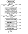
- FIG. 7 is a flowchart showing an example of safety processing executed by the robot control unit 81. This process is repeatedly executed at predetermined time intervals (for example, every several milliseconds or tens of milliseconds) from the transition to the safe state until the end of the safe state.
- the robot control unit 81 When the safety process is executed, the robot control unit 81 first inputs the elevation position Z1 of the elevation axis J1 and the rotation angles ⁇ 2 to ⁇ 7 of the joint axes J2 to J7 from the encoders 35b to 37b, 44b, and 55b to 57b ( S200), the hand position P, the retraction distance L, and the retraction speed V are calculated (S210).
- the calculation of the hand position P has been described above.
- the evacuation distance L is the cumulative amount of movement of the hand position P after transitioning to the safe state, and can be calculated by integrating the distance between the hand position P calculated this time and the hand position calculated last time. .
- the retreat speed V can be calculated by dividing the distance between the currently calculated hand position P and the previously calculated hand position by the safety process execution time interval.
- the robot control unit 81 determines whether the hand position P is within the restricted area (S220), whether the evacuation distance L exceeds the threshold Lref (S230), and whether the evacuation speed V exceeds the threshold Vref. (S240) and whether a predetermined time has elapsed since transition to the safe state (S250).
- the robot control unit 81 determines that the hand position P is not within the restricted area, the evacuation distance L is less than or equal to the threshold value Lref, the evacuation speed V is less than or equal to the threshold value Vref, and a predetermined period of time has elapsed since the transition to the safe state.
- the robot control unit 81 sets a compensation torque Tc1 for the vertical axis J1 based on the calculated vertical speed V1, and also sets a compensation torque Tc2 to Tc7 for the joint axes J2 to J7 based on the calculated angular velocities ⁇ 2 to ⁇ 7. (S270).
- the robot control unit 81 sets the torque that is the original torque that should be output to the lifting axis Z1 and the compensation torque Tc1 added to it as the torque command for the lifting axis Z1, and also sets the torque that is the original torque that should be output to the lifting axis Z1 to the original torque that should be output to each of the joint axes J2 to J7.
- the torque obtained by adding each compensation torque Tc2 to Tc7 to the torque is set as the torque command for the joint axes J2 to J7 (S280).
- the robot control unit 81 controls each motor 35a to 37a, 44a, and 55a to 57a so that a torque corresponding to the set torque command is output (S290), and ends the safety process.
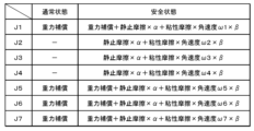
- FIG. 8 is an explanatory diagram showing compensation torques of the elevating axis J1 and each of the joint axes J2 to J7, which are set respectively in the normal state and the safe state.
- the compensation torques Tc1 to Tc7 include a compensation torque for static friction (static friction compensation) and a compensation torque for viscous friction (viscous friction compensation).
- the above-mentioned torque corresponding to the vertical speed V1 and the angular velocities ⁇ 2 to ⁇ 7 is added to the viscous friction compensation term.
- the compensation torques of the lifting axis J1 and the joint axes J5 to J7 include a compensation torque (gravity compensation) in a direction that cancels out the load torque due to the body's own weight in both the normal state and the safe state. Since the joint axes J2 to J4 extend vertically in the axial direction, gravity compensation is not necessary.
- the robot device 20 can evacuate the robot arm 21 that collided with the object (worker) in a direction away from the object.
- the pressing force of the robot arm 21 can be quickly relaxed, and the safety of the worker can be sufficiently ensured.
- the retracting operation of the robot arm 21 is executed by a torque corresponding to an external force acting on the robot arm 21. Therefore, if the external force is no longer applied to the robot arm 21, the torque corresponding to the external force will not be output. This allows the robot device 20 to retreat the robot arm 21 by the amount necessary to alleviate the pushing force, thereby suppressing the occurrence of secondary damage such as collision with another object during the retreat operation, for example. be able to.
- the robot control unit 81 determines that the hand position P is within the restricted area in S220, determines that the retraction distance L exceeds the threshold value Lref in S230, or determines that the retraction speed V exceeds the threshold value Vref in S240. If it is determined that there is, or that a predetermined time has elapsed since the transition to the safe state in S250, the safe state is ended (S300) and the safety process is ended. Specifically, the robot control unit 81 controls each motor 35a to 37a, 44a, and 55a to 57a so that the retracting operation of the robot arm 21 is stopped. Thereby, it is possible to avoid an unexpected movement in the retracting operation of the robot arm 21, and to suppress the occurrence of secondary damage.
- the robot arm 21 of this embodiment corresponds to the robot main body
- the motors 35a to 37a, 44a, and 55a to 57a correspond to the drive section
- the encoders 35b to 37b, 44b, and 55b to 57b correspond to the external force detection section
- the robot control section 81 corresponds to the control section.
- the encoders 35b to 37b, 44b, and 55b to 57b also correspond to the position detection section.
- the ultrasonic probe 101 corresponds to an ultrasonic probe.
- the robot device 20 determines whether the vertical speed V1 of the vertical axis J1 and the angular velocities ⁇ 2 to ⁇ 7 of the joint axes J2 to J7 are larger than the corresponding thresholds Z1ref, ⁇ 2ref to ⁇ 7ref.
- the external force acting on the robot arm 21 due to a collision with another object is detected.
- the robot device 20 detects the external force acting on the robot arm 21 due to a collision with another object by detecting the torque acting on the lifting axis J1 and the joint axes J2 to J7 using a torque sensor. It's okay.
- the robot control unit 81 may set a compensation torque corresponding to (proportional to) the detected torque in the direction of the detected torque. Further, the robot device 20 may directly detect the external force acting on the robot arm 21 using the force sensor 61. In this case, as the external force acting on the robot arm 21, the force sensor 61 detects force components acting in the directions of the X, Y, and Z axes, and torque components acting around each axis. Therefore, the robot control unit 81 uses a conversion matrix to convert the force component and torque component detected by the force sensor 61 into the torque of the vertical axis J1 and each joint axis J2 to J7, and sets the compensation torque. good.
- the robot control unit 81 sets the robot arm 21 in the direction of the external force acting on the robot arm 21 due to the collision with another object (the direction of the vertical speed V1 and the angular velocities ⁇ 2 to ⁇ 7) as the retraction direction.
- the motors 35a to 37a, 44a, and 55a to 57a are controlled so that the motor 21 is retracted.
- the robot control unit 81 sets the direction of the retracting motion of the robot arm 21 to be opposite to the direction of the motion of the robot arm 21 at the time of the collision (the vertical direction of the vertical axis J1, the rotational direction of the joint axes J2 to J7). You may.
- the robot device 20 is configured as a seven-axis articulated robot capable of translational movement in three directions and rotational movement in three directions.
- the number of axes may be any number.
- the robot device 20 may be configured by a so-called vertically articulated robot, horizontally articulated robot, or the like.
- the robot device of the present disclosure controls the drive unit so that the robot body moves in a predetermined direction when an external force acting on the robot body due to contact with an object is detected.
- the pushing force of the robot body can be alleviated, and the safety of workers and the like can be further improved.
- control unit may control the drive unit so that, as the safe state, the larger the detected external force is, the larger the driving force is used to cause the robot main body to retreat. In this way, when the robot body collides with another object (worker), the pushing force of the robot body can be reduced by the necessary amount, and the safety of the worker etc. can be further improved.
- control unit may control the drive unit so that the robot main body performs a retracting operation in the direction of the detected external force as the safe state. In this way, the retraction direction of the robot body can be appropriately determined through simple processing.
- the robot device of the present disclosure includes a position detection unit that detects the position of the robot body, the robot body is a robot body of a medical robot used for diagnosis and treatment of patients, and the control unit includes: The robot controls the drive unit so that the robot body operates based on the assumed thigh position of the patient, and the robot body is detected by the position detection unit when an external force acting on the robot body is detected.
- the thigh position may be changed based on the position of the main body. In this way, when working on a patient's thigh, it is possible to appropriately grasp the position of the thigh, which varies from person to person.
- the control unit may terminate the retreating operation when the robot main body enters a restricted area set within a movable area due to the retreating operation in the safe state. .
- the controller includes a position detection unit that detects the position of the robot body, and the control unit controls the robot body detected by the position detection unit when an external force acting on the robot body is detected by the external force detection unit.
- a predetermined range with the position of the main body as a boundary may be set as the restricted area. In this way, the restriction area can be set appropriately.
- control unit may control, when a predetermined period of time has elapsed since the transition to the safe state, and when the amount of movement of the robot main body in the evacuation operation exceeds a predetermined amount in the safe state;
- the evacuation operation may be terminated when the moving speed of the robot main body during the evacuation operation exceeds a predetermined speed in the safe state. In this way, it is possible to avoid unexpected operations during the evacuation operation and to suppress the occurrence of secondary damage.
- the robot main body has an arm
- the drive section has a motor that drives a joint shaft of the arm
- the external force detection section is configured to detect an external force acting on the robot main body. detects the angular velocity of the joint shaft or the torque acting on the joint shaft, and the control unit, in the safe state, applies an additional torque corresponding to the detected angular velocity or torque to the detected angular velocity from the corresponding motor.
- the drive unit may be controlled so that the torque is output in the direction of torque. In this way, the evacuation operation can be performed appropriately.
- the robot main body includes an arm
- the drive unit includes a motor that drives a joint shaft of the arm
- the external force detection unit detects a force provided on the arm.
- the control unit controls the drive unit so that, in the safe state, an additional torque corresponding to the detected value of the force sensor is output from the corresponding motor in the direction of the detected external force. You may. In this way, the evacuation operation can be performed appropriately.
- the present disclosure is not limited to the form of a robot device, but can also be applied to an ultrasonic diagnostic system.
- the present disclosure can be used in the manufacturing industry of robotic devices and ultrasonic diagnostic systems.
Abstract
This robot device comprises: a robot body; a driving unit that drives the robot body; an external force detecting unit that detects an external force acting on the robot body; and a control unit that transitions to a safe state for controlling the driving unit so that the robot body performs an evacuation action in a prescribed direction when an external force acting on the robot body has been detected by the external force detecting unit.
Description
本明細書は、ロボット装置および超音波診断システムについて開示する。
This specification discloses a robotic device and an ultrasound diagnostic system.
従来、この種のロボット装置としては、ロボットが物体に衝突したことを検知する衝突検知部と、ロボットが物体に衝突したことが検知された場合にロボットの各モータを減速させるように駆動する減速制御を実行する第1制御部と、減速制御が実行された後、各モータへの電力供給を停止させ且つ各モータにおいて電力入出力端子間を短絡させるダイナミックブレーキを所定時間実行する第2制御部と、を備えるものが提案されている(例えば、特許文献1参照)。このロボット装置では、ロボットが物体に衝突した場合に、ロボットを速やかに減速させることができ、作業者が負傷することを抑制することができる。また、作業者は、ダイナミックブレーキが実行されている間、ロボットを押して動かしたり、ロボットから離れたりすることができる。
Conventionally, this type of robot device has a collision detection unit that detects when the robot has collided with an object, and a deceleration unit that drives each motor of the robot to decelerate when it is detected that the robot has collided with an object. A first control unit that executes control; and a second control unit that executes dynamic braking for a predetermined period of time after the deceleration control is executed, stopping power supply to each motor and short-circuiting power input and output terminals in each motor. A device comprising the following has been proposed (see, for example, Patent Document 1). With this robot device, when the robot collides with an object, the robot can be quickly decelerated, and injuries to workers can be suppressed. Additionally, the operator can push the robot to move or move away from the robot while dynamic braking is being performed.
しかしながら、上述したロボット装置では、ロボットが作業者に衝突した場合に、ロボットの各モータを減速したり、ダイナミックブレーキを実行したりするだけでは、ロボットから作業者に加わる力(押し込み力)が残存し、作業者の安全性を十分に確保できない場合が生じる。
However, in the above-mentioned robot device, when the robot collides with a worker, it is not possible to simply decelerate each motor of the robot or perform dynamic braking, and the force (pushing force) applied from the robot to the worker remains. However, there may be cases where worker safety cannot be sufficiently ensured.
本開示は、ロボットと物体との衝突に対してより安全性を高めることができるロボット装置またはロボット装置を備える超音波診断システムを提供することを主目的とする。
The main purpose of the present disclosure is to provide a robot device or an ultrasound diagnostic system equipped with a robot device that can further improve safety against collisions between a robot and an object.
本開示は、上述の主目的を達成するために以下の手段を採った。
The present disclosure has taken the following measures to achieve the above-mentioned main objective.
本開示のロボット装置は、
ロボット本体と、
前記ロボット本体を駆動する駆動部と、
前記ロボット本体に作用する外力を検出する外力検出部と、
前記外力検出部により前記ロボット本体に作用する外力が検出されたとき、前記ロボット本体が所定の方向に退避動作するよう前記駆動部を制御する安全状態へ移行する制御部と、
を備えることを要旨とする。 The robot device of the present disclosure includes:
The robot body,
a drive unit that drives the robot body;
an external force detection unit that detects an external force acting on the robot body;
a control unit that controls the drive unit to move to a safe state so that the robot body moves in a predetermined direction when an external force acting on the robot body is detected by the external force detection unit;
The main point is to have the following.
この本開示のロボット装置は、物体との接触によりロボット本体に作用する外力が検出されると、ロボット本体が所定の方向に退避動作するよう駆動部を制御する。これにより、ロボット本体が物体と衝突した際に、ロボット本体の押し込み力を緩和することが可能となり、作業者等の安全性をより高めることができる。
The robot device of the present disclosure controls the drive unit so that the robot body moves in a predetermined direction when an external force acting on the robot body due to contact with an object is detected. As a result, when the robot body collides with an object, the pushing force of the robot body can be alleviated, and the safety of workers and the like can be further improved.
本開示の超音波診断システムは、超音波プローブと、超音波プローブを手先に保持する本開示のロボット装置と、を備えるため、本開示のロボット装置と同様の効果を奏することができる。
Since the ultrasound diagnostic system of the present disclosure includes an ultrasound probe and the robot device of the present disclosure that holds the ultrasound probe in its hand, it can achieve the same effects as the robot device of the present disclosure.
次に、本開示を実施するための形態について図面を参照しながら説明する。
Next, embodiments for carrying out the present disclosure will be described with reference to the drawings.
図1は、本実施形態のロボット装置20を含む超音波診断システム10の外観斜視図である。図2は、ロボット装置20の側面図である。図3は、ロボット装置20と超音波診断装置100との電気的な接続関係を示すブロック図である。なお、図1中、左右方向がX軸であり、前後方向がY軸方向であり、上下方向がZ軸方向である。
FIG. 1 is an external perspective view of an ultrasound diagnostic system 10 including a robot device 20 of this embodiment. FIG. 2 is a side view of the robot device 20. FIG. 3 is a block diagram showing the electrical connection relationship between the robot device 20 and the ultrasound diagnostic device 100. In addition, in FIG. 1, the left-right direction is the X-axis direction, the front-back direction is the Y-axis direction, and the up-down direction is the Z-axis direction.
本実施形態の超音波診断システム10は、ロボットアーム21の手先に超音波プローブ101を保持し、超音波プローブ101が患者の体表面に押し当てられるようにロボット装置20を動作させることにより超音波エコー画像を取得する。この超音波診断システム10は、例えばカテーテル治療に用いられる。カテーテルのガイドワイヤを操作する作業者(術者)は、超音波プローブ101を患者の大腿部表面に押し当て、得られる超音波エコー画像からガイドワイヤの先端と血管との位置関係を認識しながら、ガイドワイヤを進めることで、ガイドワイヤを正確に血管の閉塞部位や狭窄部位の中央を通すことができる。
The ultrasonic diagnostic system 10 of this embodiment holds an ultrasonic probe 101 at the tip of a robot arm 21, and operates the robot device 20 so that the ultrasonic probe 101 is pressed against the patient's body surface. Obtain an echo image. This ultrasonic diagnostic system 10 is used for catheter treatment, for example. The operator (operator) who operates the guide wire of the catheter presses the ultrasound probe 101 against the surface of the patient's thigh and recognizes the positional relationship between the tip of the guide wire and the blood vessel from the obtained ultrasound echo image. However, by advancing the guidewire, it is possible to accurately pass the guidewire through the center of the occluded or stenosed region of the blood vessel.
本実施形態の超音波診断システム10は、図1~図3に示すように、ロボット装置20と、コンソール装置90と、超音波診断装置100と、を備える。
The ultrasound diagnostic system 10 of this embodiment includes a robot device 20, a console device 90, and an ultrasound diagnostic device 100, as shown in FIGS. 1 to 3.
超音波診断装置100は、図1に示すように、超音波プローブ101と、超音波プローブ101とケーブル102を介して接続された超音波診断装置本体110と、を備える。超音波診断装置本体110は、図3に示すように、装置全体の制御を司る超音波診断制御部111と、超音波プローブ101からの受信信号を処理して超音波エコー画像を生成する画像処理部112と、超音波エコー画像を表示する画像表示部113と、各種操作スイッチ(図示せず)と、を備える。
As shown in FIG. 1, the ultrasound diagnostic device 100 includes an ultrasound probe 101 and an ultrasound diagnostic device main body 110 connected to the ultrasound probe 101 via a cable 102. As shown in FIG. 3, the ultrasound diagnostic device main body 110 includes an ultrasound diagnostic control unit 111 that controls the entire device, and an image processing unit that processes received signals from the ultrasound probe 101 to generate ultrasound echo images. 112, an image display section 113 that displays an ultrasound echo image, and various operation switches (not shown).
コンソール装置90は、ロボット装置20とは別体に設けられ、ロボット装置20の各種動作を指示すると共にロボット装置20の状態を含む各種情報を表示するものである。コンソール装置90は、装置全体の制御を司るコンソール制御部91と、各種情報を表示すると共に作業者によりタッチ操作可能な操作パネル92と、スピーカ93と、ロボット装置20と通信する通信部94と、非常停止スイッチ95と、を備える。非常停止スイッチ95は、非常時にロボット装置20の動作を停止させるためのスイッチである。更に、コンソール装置90は、フットペダル96やジョイントコントローラ97がケーブルを介して接続されている。フットペダル96やジョイントコントローラ97は、各種指示が可能な操作部材である。
The console device 90 is provided separately from the robot device 20 and is used to instruct various operations of the robot device 20 and display various information including the status of the robot device 20. The console device 90 includes a console control section 91 that controls the entire device, an operation panel 92 that displays various information and can be touch-operated by an operator, a speaker 93, and a communication section 94 that communicates with the robot device 20. An emergency stop switch 95 is provided. The emergency stop switch 95 is a switch for stopping the operation of the robot device 20 in an emergency. Further, the console device 90 is connected to a foot pedal 96 and a joint controller 97 via a cable. The foot pedal 96 and the joint controller 97 are operating members that can give various instructions.
ロボット装置20は、図1~図3に示すように、基台25と、基台25上に設置されたロボットアーム21と、手動操作によりロボットアーム21の高さを調整する高さ調整機構45と、ロボットアーム21を制御するロボット制御装置80(図3参照)と、を備える。
As shown in FIGS. 1 to 3, the robot device 20 includes a base 25, a robot arm 21 installed on the base 25, and a height adjustment mechanism 45 that adjusts the height of the robot arm 21 by manual operation. and a robot control device 80 (see FIG. 3) that controls the robot arm 21.
基台25の裏面の四隅には、図1,図2に示すように、ストッパ付きのキャスター26が取り付けられている。ロボット装置20は、キャスター26により自由に移動させることが可能である。また、基台25の裏面の複数箇所(例えば3箇所)には、レバー27を押し下げることにより鉛直下方向に突出してロボット装置20を移動不能にロック(固定)するロック部28が設けられている。
Casters 26 with stoppers are attached to the four corners of the back surface of the base 25, as shown in FIGS. 1 and 2. The robot device 20 can be freely moved by casters 26. Furthermore, locking portions 28 are provided at multiple locations (for example, three locations) on the back surface of the base 25 to protrude vertically downward by pressing down on the lever 27 to lock (fix) the robot device 20 immovably. .
ロボットアーム21は、図1に示すように、第1アーム22と第2アーム23とベース24と第1アーム駆動装置35と第2アーム駆動装置36と姿勢保持装置37と回転3軸機構50とを有する。
The robot arm 21, as shown in FIG. has.
第1アーム22の基端部は、上下方向(Z軸方向)に延在する第1関節軸31(以下、「関節軸J2」と称する場合がある)を介してベース24に連結されている。第1アーム駆動装置35は、モータ35aとエンコーダ35bとアンプ35cとを備える。モータ35aの回転軸は、図示しない減速機を介して第1関節軸31に接続されている。第1アーム駆動装置35は、モータ35aにより第1関節軸31を回転駆動することにより、第1関節軸31を支点に第1アーム22を水平面(XY平面)に沿って回動(旋回)させる。エンコーダ35bは、モータ35aの回転軸に取り付けられ、モータ35aの回転変位量を検出するロータリエンコーダとして構成される。アンプ35cは、スイッチング素子のスイッチングによりモータ35aを駆動するための駆動部である。
The base end of the first arm 22 is connected to the base 24 via a first joint shaft 31 (hereinafter sometimes referred to as "joint shaft J2") that extends in the vertical direction (Z-axis direction). . The first arm drive device 35 includes a motor 35a, an encoder 35b, and an amplifier 35c. The rotating shaft of the motor 35a is connected to the first joint shaft 31 via a reduction gear (not shown). The first arm driving device 35 rotates (swivels) the first arm 22 along a horizontal plane (XY plane) using the first joint axis 31 as a fulcrum by rotationally driving the first joint axis 31 with a motor 35a. . The encoder 35b is attached to the rotating shaft of the motor 35a, and is configured as a rotary encoder that detects the amount of rotational displacement of the motor 35a. The amplifier 35c is a drive unit for driving the motor 35a by switching a switching element.
第2アーム23の基端部は、上下方向に延在する第2関節軸32(以下、「関節軸J3」と称する場合がある)を介して第1アーム22の先端部に連結されている。第2アーム駆動装置36は、モータ36aとエンコーダ36bとアンプ36cとを備える。モータ36aの回転軸は、図示しない減速機を介して第2関節軸32に接続されている。第2アーム駆動装置36は、モータ36aにより第2関節軸32を回転駆動することにより、第2関節軸32を支点に第2アーム23を水平面に沿って回動(旋回)させる。エンコーダ36bは、モータ36aの回転軸に取り付けられ、モータ36aの回転変位量を検出するロータリエンコーダとして構成される。アンプ36cは、スイッチング素子のスイッチングによりモータ35aを駆動するための駆動部である。
The base end of the second arm 23 is connected to the distal end of the first arm 22 via a second joint shaft 32 (hereinafter sometimes referred to as "joint shaft J3") that extends in the vertical direction. . The second arm drive device 36 includes a motor 36a, an encoder 36b, and an amplifier 36c. The rotating shaft of the motor 36a is connected to the second joint shaft 32 via a speed reducer (not shown). The second arm driving device 36 rotates (swivels) the second arm 23 along a horizontal plane using the second joint shaft 32 as a fulcrum by rotationally driving the second joint shaft 32 with a motor 36a. The encoder 36b is attached to the rotating shaft of the motor 36a, and is configured as a rotary encoder that detects the amount of rotational displacement of the motor 36a. The amplifier 36c is a drive section for driving the motor 35a by switching a switching element.
ベース24は、基台25上に設置された昇降装置40により、基台25に対して昇降可能に設けられている。昇降装置40は、図1および図2に示すように、ベース24に固定された第1スライダ41と、上下方向に延出して第1スライダ41の移動をガイドする第1ガイド部材42と、上下方向に延出すると共に第1スライダ41に固定されたボールねじナット(図示せず)が螺合される第1ボールねじ軸43(以下、「昇降軸J1」と称する場合がある)と、第1ボールねじ軸43を回転駆動するモータ44aと、エンコーダ44b(図3参照)と、モータ44aを駆動するアンプ44cと、を備える。昇降装置40は、モータ44aにより第1ボールねじ軸43を回転駆動することにより、第1スライダ41に固定されたベース24を第1ガイド部材42に沿って上下に移動させる。このため、ロボットアーム21は、昇降軸J1に沿って上下に移動する。エンコーダ44bは、第1スライダ41(ベース24)の上下方向における位置(昇降位置)を検出するリニアエンコーダとして構成される。
The base 24 is provided so as to be movable up and down relative to the base 25 by a lifting device 40 installed on the base 25. As shown in FIGS. 1 and 2, the elevating device 40 includes a first slider 41 fixed to the base 24, a first guide member 42 that extends in the vertical direction and guides the movement of the first slider 41, and A first ball screw shaft 43 (hereinafter sometimes referred to as "elevating shaft J1") that extends in the direction and is screwed with a ball screw nut (not shown) fixed to the first slider 41; The motor 44a includes a motor 44a that rotationally drives a ball screw shaft 43, an encoder 44b (see FIG. 3), and an amplifier 44c that drives the motor 44a. The lifting device 40 moves the base 24 fixed to the first slider 41 up and down along the first guide member 42 by rotationally driving the first ball screw shaft 43 by the motor 44a. Therefore, the robot arm 21 moves up and down along the lifting axis J1. The encoder 44b is configured as a linear encoder that detects the vertical position (elevating position) of the first slider 41 (base 24).
高さ調整機構45は、図2に示すように、昇降装置40の第1ガイド部材42に固定された第2スライダ46と、基台25に固定されると共に上下方向に延出して第2スライダ46の移動をガイドする第2ガイド部材47と、上下方向に延出すると共に第2スライダ46に固定されたボールねじナット(図示せず)が螺合される第2ボールねじ軸48(昇降軸)と、動力伝達機構(傘歯車)を介して第2ボールねじ軸48に連結された操作ハンドル49と、を備える。高さ調整機構45は、操作ハンドル49の手動操作により第2ボールねじ軸48を回転駆動することにより、第2スライダ46に固定された昇降装置40の第1ガイド部材42を第2ガイド部材47に沿って上下に移動させる。ロボットアーム21の基端は、ベース24に固定され、当該ベース24は、第1ガイド部材42に支持されているから、高さ調整機構45により第1ガイド部材42を上下に移動させることで、ロボットアーム21の高さを調整することができる。これにより、例えば、超音波診断の被験者(患者)が横たわるベッドの高さに応じてロボットアーム21の高さを調整することができる。
As shown in FIG. 2, the height adjustment mechanism 45 includes a second slider 46 fixed to the first guide member 42 of the lifting device 40, and a second slider 46 fixed to the base 25 and extending in the vertical direction. A second guide member 47 that guides the movement of the second slider 46 and a second ball screw shaft 48 (elevating shaft) that extends in the vertical direction and is screwed with a ball screw nut (not shown) fixed to the second slider ) and an operation handle 49 connected to the second ball screw shaft 48 via a power transmission mechanism (bevel gear). The height adjustment mechanism 45 rotates the second ball screw shaft 48 by manually operating the operating handle 49, thereby moving the first guide member 42 of the lifting device 40 fixed to the second slider 46 to the second guide member 47. Move up and down along. The base end of the robot arm 21 is fixed to the base 24, and the base 24 is supported by the first guide member 42, so by moving the first guide member 42 up and down by the height adjustment mechanism 45, The height of the robot arm 21 can be adjusted. Thereby, for example, the height of the robot arm 21 can be adjusted according to the height of the bed on which the subject (patient) for ultrasound diagnosis lies.
回転3軸機構50は、図1,図2に示すように、上下方向に延在する姿勢保持用軸33(以下、「関節軸J4」と称する場合がある)を介して第2アーム23の先端部に連結されている。回転3軸機構50は、互いに直交する第1回転軸51(以下、「関節軸J5」と称する場合がある),第2回転軸52(以下、「関節軸J6」と称する場合がある)および第3回転軸53(以下、「関節軸J7」と称する場合がある)と、第1回転軸51を回転させる第1回転装置55と、第2回転軸52を回転させる第2回転装置56と、第3回転軸53を回転させる第3回転装置57と、を備える。第1回転軸51は、姿勢保持用軸33に対して直交姿勢で支持されている。第2回転軸52は、第1回転軸51に対して直交姿勢で支持されている。第3回転軸53は、第2回転軸52に対して直交姿勢で支持される。第1回転装置55は、第1回転軸51を回転駆動するモータ55aと、モータ55aの回転軸に取り付けられモータ55aの回転変位量を検出するエンコーダ55bと、モータ55aを駆動するアンプ55cと、を有する。第2回転装置56は、第2回転軸52を回転駆動するモータ56aと、モータ56aの回転軸に取り付けられモータ56aの回転変位量を検出するエンコーダ56bと、モータ56aを駆動するアンプ56cと、を有する。第3回転装置57は、第3回転軸53を回転駆動するモータ57aと、モータ57aの回転軸に取り付けられモータ57aの回転変位量を検出するエンコーダ57bと、モータ56aを駆動するアンプ57cと、を有する。また、第3回転軸53には、超音波プローブ101を保持するための保持部60が設けられている。
As shown in FIGS. 1 and 2, the three-axis rotating mechanism 50 rotates the second arm 23 via a posture maintaining shaft 33 (hereinafter sometimes referred to as "joint axis J4") that extends in the vertical direction. Connected to the tip. The three-axis rotating mechanism 50 includes a first rotating shaft 51 (hereinafter sometimes referred to as "joint axis J5"), a second rotating shaft 52 (hereinafter sometimes referred to as "joint axis J6"), and A third rotating shaft 53 (hereinafter sometimes referred to as "joint axis J7"), a first rotating device 55 that rotates the first rotating shaft 51, and a second rotating device 56 that rotates the second rotating shaft 52. , and a third rotation device 57 that rotates the third rotation shaft 53. The first rotating shaft 51 is supported in a position orthogonal to the position maintaining shaft 33. The second rotating shaft 52 is supported in a position perpendicular to the first rotating shaft 51 . The third rotating shaft 53 is supported in a position orthogonal to the second rotating shaft 52. The first rotating device 55 includes a motor 55a that rotationally drives the first rotating shaft 51, an encoder 55b that is attached to the rotating shaft of the motor 55a and detects the amount of rotational displacement of the motor 55a, and an amplifier 55c that drives the motor 55a. has. The second rotating device 56 includes a motor 56a that rotationally drives the second rotating shaft 52, an encoder 56b that is attached to the rotating shaft of the motor 56a and detects the amount of rotational displacement of the motor 56a, and an amplifier 56c that drives the motor 56a. has. The third rotating device 57 includes a motor 57a that rotationally drives the third rotating shaft 53, an encoder 57b that is attached to the rotating shaft of the motor 57a and detects the amount of rotational displacement of the motor 57a, and an amplifier 57c that drives the motor 56a. has. Further, the third rotating shaft 53 is provided with a holding section 60 for holding the ultrasound probe 101.
保持部60は、第3回転軸53と同軸上に位置するように超音波プローブ101を保持する。本実施形態では、保持部60には、後述するティーチングモードにおいて、ロボットアーム21の手先(保持部60)に超音波プローブ101を保持させた状態で当該超音波プローブ101を作業者が手動操作する際に、手動操作を許可するスイッチ62が設けられている。これを、ダイレクトティーチングイネーブルスイッチ62として、非常時にロボットアーム21を停止させる機能を追加してもよい。
The holding unit 60 holds the ultrasound probe 101 so as to be coaxial with the third rotating shaft 53. In this embodiment, the holding part 60 has a teaching mode, which will be described later, in which a worker manually operates the ultrasonic probe 101 while holding the ultrasonic probe 101 at the tip (holding part 60) of the robot arm 21. A switch 62 is provided to permit manual operation. This may be used as a direct teaching enable switch 62 to add a function to stop the robot arm 21 in an emergency.
本実施形態のロボット装置20は、第1アーム駆動装置35と第2アーム駆動装置36と昇降装置40とによるX軸方向,Y軸方向およびZ軸方向の3方向の並進運動と、回転3軸機構50によるX軸回り(ピッチング),Y軸回り(ローリング)およびZ軸回り(ヨーイング)の3方向の回転運動との組み合わせにより、可動エリア内において超音波プローブ101を任意の姿勢で任意の位置へ移動させることができる。
The robot device 20 of the present embodiment can perform translational motion in three directions, that is, the X-axis direction, the Y-axis direction, and the Z-axis direction, by the first arm drive device 35, the second arm drive device 36, and the lifting device 40, and three rotational axes. In combination with the rotation movement of the mechanism 50 in three directions around the X axis (pitching), around the Y axis (rolling), and around the Z axis (yawing), the ultrasound probe 101 can be moved to any position in any posture within the movable area. can be moved to.
姿勢保持装置37は、第1アーム22および第2アーム23の姿勢によらず回転3軸機構50の姿勢(第1回転軸51の向き)を一定の向きに保持するものである。姿勢保持装置37は、モータ37aとエンコーダ37bとアンプ37cとを備える。モータ37aの回転軸は、図示しない減速機を介して姿勢保持用軸33に接続されている。姿勢保持装置37は、第1回転軸51の軸方向が常時、左右方向(X軸方向)となるように第1関節軸31の回転角度と第2関節軸32の回転角度とに基づいて姿勢保持用軸33の目標回転角度を設定し、姿勢保持用軸33が目標回転角度となるようにモータ37aを駆動制御する。これにより、3方向の並進運動の制御と3方向の回転運動の制御とをそれぞれ独立して行なうことが可能となり、制御が容易となる。
The posture holding device 37 maintains the posture of the rotating three-axis mechanism 50 (orientation of the first rotating shaft 51) in a constant direction regardless of the postures of the first arm 22 and the second arm 23. The posture holding device 37 includes a motor 37a, an encoder 37b, and an amplifier 37c. The rotating shaft of the motor 37a is connected to the posture maintaining shaft 33 via a reduction gear (not shown). The posture maintaining device 37 maintains the posture based on the rotation angle of the first joint shaft 31 and the rotation angle of the second joint shaft 32 so that the axial direction of the first rotation shaft 51 is always in the left-right direction (X-axis direction). A target rotation angle of the holding shaft 33 is set, and the motor 37a is drive-controlled so that the posture holding shaft 33 reaches the target rotation angle. This makes it possible to independently control translational motion in three directions and rotational motion in three directions, thereby facilitating control.
力覚センサ61は、ロボットアーム21の先端に取り付けられ、ロボットアーム21に作用する外力としてX軸,Y軸およびZ軸の各軸方向に作用する力成分と各軸周りに作用するトルク成分とを検出する。
The force sensor 61 is attached to the tip of the robot arm 21, and detects force components acting in the directions of the X, Y, and Z axes and torque components acting around each axis as external forces acting on the robot arm 21. Detect.
ロボット制御装置80は、図3に示すように、ロボット制御部81と監視部82とIO部83と通信部84と記憶部85とを備える。ロボット制御部81は、CPUやROM,RAM、周辺回路などを含むプロセッサとして構成されるものである。監視部82は、CPUやROM,RAM、周辺回路などを含むワンチップマイクロコンピュータとして構成されるものである。また、監視部82は、二重化されることもある。ロボット制御部81は、ロボットアーム21(モータ35a~37a,44a,55a~57a)の制御に係る各種処理を行なう。監視部82は、IO部83や、通信部84、アンプ35c~37c,44c,55c~57c、エンコーダ35b~37b,44b,55b~57b等を含むセンサ部といった各部の状態を監視する。IO部83は、I/Oポートであり、ダイレクトティーチングイネーブルスイッチ62からの検出信号を入力すると共に、外部機器からの信号を入出力する。通信部84は、有線または無線によりロボット制御装置80とコンソール装置90との通信を行ない、互いに各種制御信号やデータのやり取りを行なう。
As shown in FIG. 3, the robot control device 80 includes a robot control section 81, a monitoring section 82, an IO section 83, a communication section 84, and a storage section 85. The robot control unit 81 is configured as a processor including a CPU, ROM, RAM, peripheral circuits, and the like. The monitoring unit 82 is configured as a one-chip microcomputer including a CPU, ROM, RAM, peripheral circuits, and the like. Furthermore, the monitoring section 82 may be duplicated. The robot control unit 81 performs various processes related to controlling the robot arm 21 (motors 35a to 37a, 44a, 55a to 57a). The monitoring unit 82 monitors the status of each unit such as the IO unit 83, the communication unit 84, the amplifiers 35c to 37c, 44c, 55c to 57c, and the sensor unit including the encoders 35b to 37b, 44b, 55b to 57b, etc. The IO section 83 is an I/O port, and inputs a detection signal from the direct teaching enable switch 62 and inputs/outputs a signal from an external device. The communication unit 84 communicates with the robot control device 80 and the console device 90 by wire or wirelessly, and exchanges various control signals and data with each other.
アンプ35c~37c,44c,55c~57cには、それぞれ、モータ制御部71と駆動電力供給部72とIO部73とが含まれる。モータ制御部71は、スイッチング素子を有し、エンコーダ35b~37b,44b,55b~57b等からのフィードバック信号に基づいて当該スイッチング素子をスイッチング制御することで各モータ35a~37a,44a,55a~57aを制御する。駆動電力供給部72は、モータ35a~37a,44a,55a~57aの駆動に必要な電力を供給する。IO部83は、I/Oポートであり、エンコーダ35b~37b,44b,55b~57bからの位置信号や各モータ35a~37a,44a,55a~57aを流れる電流を検知する電流センサからの電流信号、ロボット制御部81から各モータ35a~37a,44a,55a~57aへの指令信号(制御信号)等の各種信号を入力する。
The amplifiers 35c to 37c, 44c, and 55c to 57c each include a motor control section 71, a drive power supply section 72, and an IO section 73. The motor control unit 71 has switching elements, and controls each motor 35a to 37a, 44a, 55a to 57a by controlling the switching elements based on feedback signals from encoders 35b to 37b, 44b, 55b to 57b, etc. control. The drive power supply section 72 supplies the power necessary to drive the motors 35a to 37a, 44a, and 55a to 57a. The IO section 83 is an I/O port, and receives position signals from the encoders 35b to 37b, 44b, and 55b to 57b, and current signals from current sensors that detect the current flowing through each motor 35a to 37a, 44a, and 55a to 57a. , various signals such as command signals (control signals) are input from the robot control unit 81 to the respective motors 35a to 37a, 44a, and 55a to 57a.
次に、こうして構成された超音波診断システム10が備えるロボット装置20の動作について説明する。本実施形態のロボット装置20は、動作モードとして、ダイレクトティーチングモードと自動操作モードとを有する。
Next, the operation of the robot device 20 included in the ultrasonic diagnostic system 10 configured in this way will be described. The robot device 20 of this embodiment has a direct teaching mode and an automatic operation mode as operating modes.
ダイレクトティーチングモードは、超音波プローブ101を保持したロボットアーム21の手先(保持部60)を作業者が把持して手動操作しながら、超音波プローブ101の位置および姿勢を任意の複数のポイントで登録可能なモードである。ダイレクトティーチングモードでは、ロボット制御部81(CPU)は、作業者からの登録指示に基づいて各エンコーダ35b~37b,44b,55b~57bからの昇降軸J1の昇降位置Z1および関節軸J2~J7の回転角度θ2~θ7を取得する。続いて、ロボット制御部81は、取得した昇降軸J1の昇降位置Z1および関節軸J2~J7の回転角度θ2~θ7に基づいて順運動学によりロボットアーム21の手先の位置および姿勢、すなわち超音波プローブ101の位置および姿勢を算出する。そして、ロボット制御部81は、取得した昇降位置Z1および回転角度θ2~θ7と算出した超音波プローブ101の位置および姿勢とを対応付けて登録ポイントとして記憶部85に記憶する。なお、作業者の登録指示は、例えば、フットペダル96の踏み込み操作や、操作パネル92の操作、音声認識による操作などにより行なうことができる。
In the direct teaching mode, the position and orientation of the ultrasound probe 101 are registered at multiple arbitrary points while the operator grasps the tip (holding part 60) of the robot arm 21 that holds the ultrasound probe 101 and manually operates it. This is a possible mode. In the direct teaching mode, the robot control unit 81 (CPU) controls the vertical position Z1 of the vertical axis J1 and the vertical position of the joint axis J2 to J7 from each encoder 35b to 37b, 44b, 55b to 57b based on registration instructions from the operator. Obtain rotation angles θ2 to θ7. Next, the robot control unit 81 determines the position and posture of the hand of the robot arm 21 using forward kinematics, that is, the ultrasonic The position and orientation of the probe 101 are calculated. Then, the robot control unit 81 associates the acquired elevation position Z1 and rotation angles θ2 to θ7 with the calculated position and orientation of the ultrasound probe 101 and stores them in the storage unit 85 as registration points. Note that the operator's registration instruction can be given by, for example, pressing the foot pedal 96, operating the operation panel 92, or using voice recognition.
ここで、ロボット装置20には、可動エリアが定められている。ダイレクトティーチングモードでは、ロボットアーム21の手先(超音波プローブ101)が可動エリアの境界に近づくと、作業者によるロボットアーム21の操作方向とは反対方向に負荷(抵抗)が加わるように各モータ35a~37a,44a,55a~57aを制御する。これにより、ロボットアーム21の手先が可動エリアを超えて操作されるのを抑制することができる。なお、ロボットアーム21の操作方向は、力覚センサ61からの検出信号やエンコーダ35b~37b,44b,55b~57bからの検出信号に基づいて判定することができる。
Here, a movable area is defined for the robot device 20. In the direct teaching mode, when the tip of the robot arm 21 (ultrasonic probe 101) approaches the boundary of the movable area, each motor 35a is moved so that a load (resistance) is applied in the opposite direction to the direction in which the robot arm 21 is operated by the operator. ~37a, 44a, 55a~57a. Thereby, it is possible to prevent the tip of the robot arm 21 from being operated beyond the movable area. Note that the operating direction of the robot arm 21 can be determined based on detection signals from the force sensor 61 and detection signals from the encoders 35b to 37b, 44b, and 55b to 57b.
自動操作モードは、ダイレクトティーチングモードによって登録された複数のポイントを予め定められた順に通過するようにロボット装置20が超音波プローブ101を自動移動させるモードである。自動操作モードにおいて、ロボット制御部81は、作業者により診断開始が指示されると、超音波プローブ101を予め登録された複数のポイントのうち最初のポイントへ移動させる。超音波プローブ101の移動は、移動させるポイント(ロボットアーム21の手先の位置および姿勢)に対応するロボットアーム21の昇降軸J1の昇降位置および関節軸J2~J7の回転角度を目標昇降位置Z1tagおよび目標回転角度θ2tag~θ7tagに設定し、各エンコーダ35b~37b,44b,55b~57bにより検出される昇降軸J1の昇降位置Z1および関節軸J2~J7の回転角度θ2~θ7が対応する目標昇降位置Z1tagおよび目標回転角度θ2tag~θ7tagと一致するように各モータ35a~37a,44a,55a~57aを制御することにより行なわれる。ロボット制御部81は、作業者により進み操作がなされると、超音波プローブ101を一つ次のポイントへ移動させる。一方、ロボット制御部81は、作業者により戻り操作がなされると、超音波プローブ101を一つ前のポイントへ移動させる。なお、進み操作や戻り操作は、例えばフットペダル96の踏み込み操作や、操作パネル92の操作、音声認識による操作などにより行なうことができる。
The automatic operation mode is a mode in which the robot device 20 automatically moves the ultrasound probe 101 so as to pass through a plurality of points registered in the direct teaching mode in a predetermined order. In the automatic operation mode, when the operator instructs the robot controller 81 to start diagnosis, the robot controller 81 moves the ultrasound probe 101 to the first point among a plurality of points registered in advance. The movement of the ultrasonic probe 101 is performed by adjusting the lifting position of the lifting axis J1 and the rotation angle of the joint axes J2 to J7 of the robot arm 21 corresponding to the point to be moved (the position and posture of the hand of the robot arm 21) to the target lifting position Z1tag and the rotation angle of the joint axes J2 to J7. The target vertical position corresponding to the vertical position Z1 of the vertical axis J1 and the rotation angle θ2 to θ7 of the joint axes J2 to J7, which are set to the target rotation angles θ2tag to θ7tag and detected by each encoder 35b to 37b, 44b, 55b to 57b. This is done by controlling each of the motors 35a to 37a, 44a, and 55a to 57a to match Z1tag and target rotation angles θ2tag to θ7tag. The robot control unit 81 moves the ultrasonic probe 101 to the next point when the operator performs a forward operation. On the other hand, when the operator performs a return operation, the robot control unit 81 moves the ultrasound probe 101 to the previous point. Note that the forward operation and return operation can be performed by, for example, depressing the foot pedal 96, operating the operation panel 92, or operating by voice recognition.
自動操作モードにおいて、コンソール装置90の操作パネル92には、図4に示すように、ダイレクトティーチングモードで登録されたポイント(移動軌跡)が三次元表示されるようになっている。作業者は、超音波プローブ101をロボット装置20に移動させる際に、超音波プローブ101の移動先を操作パネル92にて事前確認することができる。
In the automatic operation mode, the points (trajectory of movement) registered in the direct teaching mode are displayed in three dimensions on the operation panel 92 of the console device 90, as shown in FIG. When moving the ultrasonic probe 101 to the robot device 20, the operator can confirm in advance the destination of the ultrasonic probe 101 using the operation panel 92.
超音波診断をカテーテル治療に適用する場合、作業者は、超音波プローブ101のスキャン方向を患者の血管の中心軸方向(長さ方向)と一致するように予めティーチングしておけば、自動操作モードを実行することにより、フットペダル96を操作するだけで超音波プローブ101を血管の中心軸方向に自動移動させることができる。これにより、作業者一人で、超音波プローブ101を操作して超音波エコー画像から患者の血管の位置を確認しながら、ガイドワイヤを進ませることができる。
When applying ultrasonic diagnosis to catheter treatment, if the operator teaches the scanning direction of the ultrasonic probe 101 to match the central axis direction (lengthwise direction) of the patient's blood vessel in advance, automatic operation mode can be activated. By executing this, the ultrasound probe 101 can be automatically moved in the direction of the central axis of the blood vessel simply by operating the foot pedal 96. This allows a single operator to advance the guide wire while operating the ultrasound probe 101 and confirming the position of the patient's blood vessels from ultrasound echo images.
このように本実施形態のロボット装置20は、作業者と同じ空間で作業を行なうことが想定されているため、他物体(作業者)と衝突する可能性がある。このため、本実施形態のロボット装置20は、ロボットアーム21(超音波プローブ101を含む)と他物体との衝突の有無を判定し、他物体と衝突したと判定した場合に物体からロボットアーム21を退避させる安全状態に移行することとしている。
As described above, since the robot device 20 of this embodiment is assumed to work in the same space as the worker, there is a possibility that it will collide with another object (the worker). Therefore, the robot device 20 of the present embodiment determines whether or not there is a collision between the robot arm 21 (including the ultrasonic probe 101) and another object, and if it is determined that there has been a collision with another object, the robot arm 21 is moved away from the object. We are planning to move to a safe state where we will evacuate the area.
図5は、ロボット制御装置80のロボット制御部81により実行される衝突判定処理の一例を示すフローチャートである。この処理は、所定時間毎(例えば、数msec毎や数十msec毎)に繰り返し実行される。
FIG. 5 is a flowchart showing an example of a collision determination process executed by the robot control unit 81 of the robot control device 80. This process is repeatedly executed at predetermined time intervals (for example, every few milliseconds or tens of milliseconds).
衝突判定処理が実行されると、ロボット制御部81は、まず、ロボット装置20の現在の状態が通常状態であるか否かを判定する(S100)。ロボット制御部81は、現在の状態が通常状態ではなく安全状態であると判定すると、衝突判定処理を終了する。一方、ロボット制御部81は、現在の状態が通常状態であると判定すると、各エンコーダ35b~37b,44b,55b~57bから昇降軸J1の昇降位置Z1および関節軸J2~J7の回転角度θ2~θ7を入力し(S110)、入力した昇降位置Z1に基づいて昇降速度V1を算出すると共に入力した回転角度θ2~θ7に基づいて角速度ω2~ω7を算出する(S120)。そして、ロボット制御部81は、昇降位置Z1が閾値Z1refよりも大きいか否か、角速度ω2~ω7が対応する閾値ω2ref~ω7refよりも大きいか否かを判定する(S130)。ここで、閾値Z1ref,ω2ref~ω7refは、ロボットアーム21の変位が他物体との衝突に起因したものであるかを判定するための閾値であり、通常、ロボットアーム21を動作させる際の昇降軸J1の昇降速度や関節軸J2~J7の角速度の速度範囲の上限よりも若干高い速度に定められている。ロボット制御部81は、昇降速度V1が閾値V1ref以下であり且ついずれの角速度ω2~ω7も対応する閾値ω2ref~ω7ref以下であると判定すると、他物体との衝突は生じていないと判断して、衝突判定処理を終了する。
When the collision determination process is executed, the robot control unit 81 first determines whether the current state of the robot device 20 is the normal state (S100). If the robot control unit 81 determines that the current state is not a normal state but a safe state, it ends the collision determination process. On the other hand, if the robot control unit 81 determines that the current state is the normal state, the robot control unit 81 determines the vertical position Z1 of the vertical axis J1 and the rotation angle θ2 of the joint axes J2 to J7 from each encoder 35b to 37b, 44b, 55b to 57b. θ7 is input (S110), and the vertical speed V1 is calculated based on the input vertical position Z1, and the angular velocities ω2 to ω7 are calculated based on the input rotation angles θ2 to θ7 (S120). Then, the robot control unit 81 determines whether the vertical position Z1 is larger than the threshold Z1ref and whether the angular velocities ω2 to ω7 are larger than the corresponding thresholds ω2ref to ω7ref (S130). Here, the thresholds Z1ref, ω2ref to ω7ref are thresholds for determining whether the displacement of the robot arm 21 is caused by a collision with another object, and usually the vertical axis when operating the robot arm 21 is The speed is set to be slightly higher than the upper limit of the speed range of the vertical speed of J1 and the angular speed of joint axes J2 to J7. If the robot control unit 81 determines that the vertical speed V1 is equal to or lower than the threshold value V1ref and any of the angular velocities ω2 to ω7 are equal to or lower than the corresponding thresholds ω2ref to ω7ref, the robot control unit 81 determines that no collision with another object has occurred. The collision determination process ends.
一方、ロボット制御部81は、昇降速度V1が閾値V1refよりも大きいと判定したり、いずれかの角速度ω2~ω7が対応する閾値ω2ref~ω7refよりも大きいと判定すると、他物体と衝突したと判定する(S140)。続いて、ロボット制御部81は、S110で入力した昇降軸J1の昇降位置Z1および関節軸J2~J7の回転角度θ2~θ7に基づいて順運動学によりロボットアーム21の手先位置P(超音波プローブ101の位置)を算出し(S150)、算出した手先位置Pに基づいて制限エリアを更新する(S160)。そして、ロボット制御部81は、安全状態へ移行して(S170)、衝突判定処理を終了する。
On the other hand, if the robot control unit 81 determines that the vertical speed V1 is greater than the threshold value V1ref, or if it determines that any of the angular velocities ω2 to ω7 is greater than the corresponding threshold values ω2ref to ω7ref, it determines that the robot has collided with another object. (S140). Next, the robot control unit 81 uses forward kinematics to determine the hand position P of the robot arm 21 (ultrasonic probe 101 position) is calculated (S150), and the restricted area is updated based on the calculated hand position P (S160). Then, the robot control unit 81 shifts to a safe state (S170) and ends the collision determination process.
制限エリアは、可動エリアのうちロボットアーム21の動作が制限されるエリアである。超音波プローブ101を患者の大腿部表面に押し当て超音波診断する場合、大腿部のある部分が制限エリアである。本実施形態では、制限エリアは、初期エリアとして、図6に示すように、大腿部の断面視において、所定位置Oを大腿部中心として大腿部の想定される最大半径(想定最大大腿部半径)で囲まれる円形(扇形)領域に設定される。そして、ロボットアーム21が他物体(患者)と衝突したと判定されると、制限エリアは、S160において衝突時の手先位置P(超音波プローブ101の位置)と所定位置Oとの距離を半径(衝突位置半径)とした円形(扇形)領域に更新(変更)される。なお、制限エリアの形状は、大腿部の断面視において、円形(扇形)とするものに限られず、楕円形やたまご形などであってもよい。また、制限エリアは、図6の奥行き方向において、円柱形状やテーパ形状に設定されてもよい。安全状態において、ロボットアーム21の手先(超音波プローブ101)が制限エリア内に浸入した際のロボット装置20の動作については後述する。
The restricted area is an area in the movable area where the movement of the robot arm 21 is restricted. When performing ultrasonic diagnosis by pressing the ultrasound probe 101 against the surface of a patient's thigh, a certain part of the thigh is a restricted area. In this embodiment, the restriction area is an initial area, which is the assumed maximum radius of the thigh (assumed maximum It is set in a circular (fan-shaped) area surrounded by the thigh radius). Then, when it is determined that the robot arm 21 has collided with another object (patient), the restricted area is defined as the distance between the hand position P (position of the ultrasound probe 101) and the predetermined position O at the time of the collision with a radius ( The area is updated (changed) to a circular (fan-shaped) area with the collision position radius). Note that the shape of the restricted area is not limited to a circular (fan-shaped) shape in a cross-sectional view of the thigh, but may be an ellipse, an egg shape, or the like. Further, the restricted area may be set to have a cylindrical shape or a tapered shape in the depth direction in FIG. 6 . The operation of the robot device 20 when the tip of the robot arm 21 (ultrasonic probe 101) enters the restricted area in the safe state will be described later.
次に、安全状態におけるロボット装置20の動作について説明する。図7は、ロボット制御部81により実行される安全処理の一例を示すフローチャートである。この処理は、安全状態に移行してから安全状態が終了するまでの間、所定時間毎(例えば、数msec毎や数十msec毎)に繰り返し実行される。
Next, the operation of the robot device 20 in a safe state will be described. FIG. 7 is a flowchart showing an example of safety processing executed by the robot control unit 81. This process is repeatedly executed at predetermined time intervals (for example, every several milliseconds or tens of milliseconds) from the transition to the safe state until the end of the safe state.
安全処理が実行されると、ロボット制御部81は、まず、エンコーダ35b~37b,44b,55b~57bから昇降軸J1の昇降位置Z1および関節軸J2~J7の回転角度θ2~θ7を入力し(S200)、手先位置P、退避距離Lおよび退避速度Vをそれぞれ算出する(S210)。手先位置Pの算出については上述した。また、退避距離Lは、安全状態に移行してからの手先位置Pの累積移動量であり、今回算出した手先位置Pと前回算出した手先位置との距離を積算することにより算出することができる。退避速度Vは、今回算出した手先位置Pと前回算出した手先位置との距離を安全処理の実行時間間隔で除することにより算出することができる。
When the safety process is executed, the robot control unit 81 first inputs the elevation position Z1 of the elevation axis J1 and the rotation angles θ2 to θ7 of the joint axes J2 to J7 from the encoders 35b to 37b, 44b, and 55b to 57b ( S200), the hand position P, the retraction distance L, and the retraction speed V are calculated (S210). The calculation of the hand position P has been described above. In addition, the evacuation distance L is the cumulative amount of movement of the hand position P after transitioning to the safe state, and can be calculated by integrating the distance between the hand position P calculated this time and the hand position calculated last time. . The retreat speed V can be calculated by dividing the distance between the currently calculated hand position P and the previously calculated hand position by the safety process execution time interval.
次に、ロボット制御部81は、手先位置Pが制限エリア内にあるか否か(S220)、退避距離Lが閾値Lrefを超えているか否か(S230)、退避速度Vが閾値Vrefを超えているか否か(S240)、安全状態に移行してから所定時間が経過したか否か(S250)、をそれぞれ判定する。ロボット制御部81は、手先位置Pが制限エリア内になく、退避距離Lが閾値Lref以下であり、退避速度Vが閾値Vref以下であり、且つ、安全状態に移行してから所定時間が経過していないと判定すると、S200で入力した昇降位置Z1に基づいて昇降速度V1を算出すると共にS200で入力した回転角度θ2~θ7に基づいて角速度ω2~ω7を算出する(S260)。続いて、ロボット制御部81は、算出した昇降速度V1に基づいて昇降軸J1の補償トルクTc1を設定すると共に算出した角速度ω2~ω7に基づいて関節軸J2~J7の補償トルクTc2~Tc7を設定する(S270)。次に、ロボット制御部81は、昇降軸Z1に出力すべき本来のトルクに補償トルクTc1を付加したトルクを昇降軸Z1のトルク指令に設定すると共に各関節軸J2~J7に出力すべき本来のトルクに各補償トルクTc2~Tc7を付加したトルクを関節軸J2~J7のトルク指令に設定する(S280)。そして、ロボット制御部81は、設定したトルク指令に応じたトルクが出力されるよう各モータ35a~37a,44a,55a~57aを制御して(S290)、安全処理を終了する。
Next, the robot control unit 81 determines whether the hand position P is within the restricted area (S220), whether the evacuation distance L exceeds the threshold Lref (S230), and whether the evacuation speed V exceeds the threshold Vref. (S240) and whether a predetermined time has elapsed since transition to the safe state (S250). The robot control unit 81 determines that the hand position P is not within the restricted area, the evacuation distance L is less than or equal to the threshold value Lref, the evacuation speed V is less than or equal to the threshold value Vref, and a predetermined period of time has elapsed since the transition to the safe state. If it is determined that it is not, the lifting speed V1 is calculated based on the lifting position Z1 input in S200, and the angular velocities ω2 to ω7 are calculated based on the rotation angles θ2 to θ7 input in S200 (S260). Next, the robot control unit 81 sets a compensation torque Tc1 for the vertical axis J1 based on the calculated vertical speed V1, and also sets a compensation torque Tc2 to Tc7 for the joint axes J2 to J7 based on the calculated angular velocities ω2 to ω7. (S270). Next, the robot control unit 81 sets the torque that is the original torque that should be output to the lifting axis Z1 and the compensation torque Tc1 added to it as the torque command for the lifting axis Z1, and also sets the torque that is the original torque that should be output to the lifting axis Z1 to the original torque that should be output to each of the joint axes J2 to J7. The torque obtained by adding each compensation torque Tc2 to Tc7 to the torque is set as the torque command for the joint axes J2 to J7 (S280). Then, the robot control unit 81 controls each motor 35a to 37a, 44a, and 55a to 57a so that a torque corresponding to the set torque command is output (S290), and ends the safety process.
安全状態では、他物体との衝突による反力でロボットアーム21が昇降軸Z1に沿って移動した場合には、その移動方向に昇降速度V1に応じた(比例した)トルクが出力される。また、他物体との衝突による反力でロボットアーム21が関節軸J2~J7周りに回転した場合には、その回転方向に角速度ω2~ω7に応じた(比例した)トルクが出力される。図8は、通常状態と安全状態とでそれぞれ設定される昇降軸J1および各関節軸J2~J7の補償トルクを示す説明図である。安全状態において、補償トルクTc1~Tc7には、静止摩擦に対する補償トルク(静止摩擦補償)や粘性摩擦に対する補償トルク(粘性摩擦補償)が含まれる。上述した昇降速度V1や角速度ω2~ω7に応じたトルクは、粘性摩擦補償の項に付加される。なお、昇降軸J1と関節軸J5~J7の補償トルクには、通常状態および安全状態のいずれの状態でも、自重による負荷トルクを打ち消す方向の補償トルク(重力補償)が含まれる。関節軸J2~J4は、軸方向が上下に延在しているため、重力補償は不要である。
In the safe state, when the robot arm 21 moves along the lifting axis Z1 due to a reaction force due to a collision with another object, a torque corresponding to (proportional to) the lifting speed V1 is output in the moving direction. Further, when the robot arm 21 rotates around the joint axes J2 to J7 due to a reaction force due to a collision with another object, a torque corresponding to (proportional to) the angular velocities ω2 to ω7 is output in the direction of rotation. FIG. 8 is an explanatory diagram showing compensation torques of the elevating axis J1 and each of the joint axes J2 to J7, which are set respectively in the normal state and the safe state. In the safe state, the compensation torques Tc1 to Tc7 include a compensation torque for static friction (static friction compensation) and a compensation torque for viscous friction (viscous friction compensation). The above-mentioned torque corresponding to the vertical speed V1 and the angular velocities ω2 to ω7 is added to the viscous friction compensation term. Note that the compensation torques of the lifting axis J1 and the joint axes J5 to J7 include a compensation torque (gravity compensation) in a direction that cancels out the load torque due to the body's own weight in both the normal state and the safe state. Since the joint axes J2 to J4 extend vertically in the axial direction, gravity compensation is not necessary.
こうした安全処理により、ロボット装置20は、物体(作業者)と衝突したロボットアーム21を物体から離間する方向に退避させることができる。この結果、ロボットアーム21の押し付け力を素早く緩和させることができ、作業者の安全性を十分に確保することができる。また、ロボットアーム21の退避動作は、ロボットアーム21に作用した外力に応じたトルクにより実行される。このため、ロボットアーム21に外力が加わらなくなれば、外力に応じたトルクは出力されない。これにより、ロボット装置20は、押し込み力を緩和させるのに必要な分だけロボットアーム21を退避させることができるため、例えば退避動作時に他物体と衝突する等の二次的被害の発生を抑制することができる。
Through such safety processing, the robot device 20 can evacuate the robot arm 21 that collided with the object (worker) in a direction away from the object. As a result, the pressing force of the robot arm 21 can be quickly relaxed, and the safety of the worker can be sufficiently ensured. Further, the retracting operation of the robot arm 21 is executed by a torque corresponding to an external force acting on the robot arm 21. Therefore, if the external force is no longer applied to the robot arm 21, the torque corresponding to the external force will not be output. This allows the robot device 20 to retreat the robot arm 21 by the amount necessary to alleviate the pushing force, thereby suppressing the occurrence of secondary damage such as collision with another object during the retreat operation, for example. be able to.
ロボット制御部81は、S220で手先位置Pが制限エリア内にあると判定したり、S230で退避距離Lが閾値Lrefを超えていると判定したり、S240で退避速度Vが閾値Vrefを超えていると判定したり、S250で安全状態に移行してから所定時間が経過していると判定したりすると、安全状態を終了して(S300)、安全処理を終了する。具体的には、ロボット制御部81は、ロボットアーム21の退避動作が停止されるように各モータ35a~37a,44a,55a~57aを制御する。これにより、ロボットアーム21の退避動作で予期しない動作が行なわれるのを回避し、二次的被害の発生を抑制することができる。
The robot control unit 81 determines that the hand position P is within the restricted area in S220, determines that the retraction distance L exceeds the threshold value Lref in S230, or determines that the retraction speed V exceeds the threshold value Vref in S240. If it is determined that there is, or that a predetermined time has elapsed since the transition to the safe state in S250, the safe state is ended (S300) and the safety process is ended. Specifically, the robot control unit 81 controls each motor 35a to 37a, 44a, and 55a to 57a so that the retracting operation of the robot arm 21 is stopped. Thereby, it is possible to avoid an unexpected movement in the retracting operation of the robot arm 21, and to suppress the occurrence of secondary damage.
ここで、実施形態の主要な要素と請求の範囲に記載した本開示の主要な要素との対応関係について説明する。即ち、本実施形態のロボットアーム21がロボット本体に相当し、モータ35a~37a,44a,55a~57aが駆動部に相当し、エンコーダ35b~37b,44b,55b~57bが外力検出部に相当し、ロボット制御部81が制御部に相当する。エンコーダ35b~37b,44b,55b~57bが位置検出部にも相当する。また、超音波プローブ101が超音波プローブに相当する。
Here, the correspondence between the main elements of the embodiment and the main elements of the present disclosure described in the claims will be explained. That is, the robot arm 21 of this embodiment corresponds to the robot main body, the motors 35a to 37a, 44a, and 55a to 57a correspond to the drive section, and the encoders 35b to 37b, 44b, and 55b to 57b correspond to the external force detection section. , the robot control section 81 corresponds to the control section. The encoders 35b to 37b, 44b, and 55b to 57b also correspond to the position detection section. Further, the ultrasonic probe 101 corresponds to an ultrasonic probe.
なお、本開示は上述した実施形態に何ら限定されることはなく、本開示の技術的範囲に属する限り種々の態様で実施し得ることはいうまでもない。
It goes without saying that the present disclosure is not limited to the embodiments described above, and can be implemented in various forms as long as they fall within the technical scope of the present disclosure.
例えば、上述した実施形態では、ロボット装置20は、昇降軸J1の昇降速度V1や関節軸J2~J7の角速度ω2~ω7が対応する閾値Z1ref,ω2ref~ω7refよりも大きいか否かを判定することにより他物体との衝突に起因してロボットアーム21に作用する外力を検出するものとした。しかし、ロボット装置20は、トルクセンサで昇降軸J1や関節軸J2~J7に作用するトルクを検出することにより、他物体との衝突に起因してロボットアーム21に作用する外力を検出するようにしてもよい。この場合、ロボット制御部81は、検出トルクの方向に検出トルクに応じた(比例した)補償トルクを設定すればよい。また、ロボット装置20は、力覚センサ61によりロボットアーム21に作用する外力を直接検出するようにしてもよい。この場合、ロボットアーム21に作用する外力として、力覚センサ61によりX軸,Y軸およびZ軸の各軸方向に作用する力成分と各軸周りに作用するトルク成分とが検出される。このため、ロボット制御部81は、変換行列を用いて力覚センサ61により検出される力成分およびトルク成分を昇降軸J1および各関節軸J2~J7のトルクに変換して補償トルクを設定すればよい。
For example, in the embodiment described above, the robot device 20 determines whether the vertical speed V1 of the vertical axis J1 and the angular velocities ω2 to ω7 of the joint axes J2 to J7 are larger than the corresponding thresholds Z1ref, ω2ref to ω7ref. The external force acting on the robot arm 21 due to a collision with another object is detected. However, the robot device 20 detects the external force acting on the robot arm 21 due to a collision with another object by detecting the torque acting on the lifting axis J1 and the joint axes J2 to J7 using a torque sensor. It's okay. In this case, the robot control unit 81 may set a compensation torque corresponding to (proportional to) the detected torque in the direction of the detected torque. Further, the robot device 20 may directly detect the external force acting on the robot arm 21 using the force sensor 61. In this case, as the external force acting on the robot arm 21, the force sensor 61 detects force components acting in the directions of the X, Y, and Z axes, and torque components acting around each axis. Therefore, the robot control unit 81 uses a conversion matrix to convert the force component and torque component detected by the force sensor 61 into the torque of the vertical axis J1 and each joint axis J2 to J7, and sets the compensation torque. good.
また、上述した実施形態では、ロボット制御部81は、他物体との衝突に起因してロボットアーム21に作用する外力の方向(昇降速度V1や角速度ω2~ω7の方向)を退避方向としてロボットアーム21が退避するように各モータ35a~37a,44a,55a~57aを制御するものとした。しかし、ロボット制御部81は、ロボットアーム21の退避動作の方向を、衝突時のロボットアーム21の動作の方向(昇降軸J1の昇降方向、関節軸J2~J7の回転方向)と反対方向に設定してもよい。
Further, in the embodiment described above, the robot control unit 81 sets the robot arm 21 in the direction of the external force acting on the robot arm 21 due to the collision with another object (the direction of the vertical speed V1 and the angular velocities ω2 to ω7) as the retraction direction. The motors 35a to 37a, 44a, and 55a to 57a are controlled so that the motor 21 is retracted. However, the robot control unit 81 sets the direction of the retracting motion of the robot arm 21 to be opposite to the direction of the motion of the robot arm 21 at the time of the collision (the vertical direction of the vertical axis J1, the rotational direction of the joint axes J2 to J7). You may.
また、上述した実施形態では、ロボット装置20は、3方向の並進運動と3方向の回転運動とが可能な7軸の多関節ロボットとして構成されるものとした。しかし、軸の数はいくつであっても構わない。また、ロボット装置20は、いわゆる垂直多関節ロボットや水平多関節ロボットなどにより構成されてもよい。
Furthermore, in the embodiment described above, the robot device 20 is configured as a seven-axis articulated robot capable of translational movement in three directions and rotational movement in three directions. However, the number of axes may be any number. Further, the robot device 20 may be configured by a so-called vertically articulated robot, horizontally articulated robot, or the like.
以上説明したように、本開示のロボット装置は、物体との接触によりロボット本体に作用する外力が検出されると、ロボット本体が所定の方向に退避動作するよう駆動部を制御する。これにより、ロボット本体が物体と衝突した際に、ロボット本体の押し込み力を緩和することが可能となり、作業者等の安全性をより高めることができる。
As described above, the robot device of the present disclosure controls the drive unit so that the robot body moves in a predetermined direction when an external force acting on the robot body due to contact with an object is detected. As a result, when the robot body collides with an object, the pushing force of the robot body can be alleviated, and the safety of workers and the like can be further improved.
こうした本開示のロボット装置において、前記制御部は、前記安全状態として、前記検出された外力が大きいほど大きな駆動力により前記ロボット本体が退避動作するよう前記駆動部を制御してもよい。こうすれば、ロボット本体が他物体(作業者)と衝突した際に、ロボット本体の押し込み力を必要な分だけ緩和することができ、作業者等の安全性をより高めることができる。
In such a robot device of the present disclosure, the control unit may control the drive unit so that, as the safe state, the larger the detected external force is, the larger the driving force is used to cause the robot main body to retreat. In this way, when the robot body collides with another object (worker), the pushing force of the robot body can be reduced by the necessary amount, and the safety of the worker etc. can be further improved.
また、本開示のロボット装置において、前記制御部は、前記安全状態として、前記検出された外力の方向に前記ロボット本体が退避動作するよう前記駆動部を制御してもよい。こうすれば、ロボット本体の退避方向を簡易な処理により適切に定めることができる。
Furthermore, in the robot device of the present disclosure, the control unit may control the drive unit so that the robot main body performs a retracting operation in the direction of the detected external force as the safe state. In this way, the retraction direction of the robot body can be appropriately determined through simple processing.
さらに、本開示のロボット装置において、前記ロボット本体の位置を検出する位置検出部を備え、前記ロボット本体は、患者の診断や治療に用いられる医療用ロボットのロボット本体であり、前記制御部は、前記患者の想定される大腿部位置に基づいて前記ロボット本体が動作するように前記駆動部を制御し、前記ロボット本体に作用する外力が検出されたときに前記位置検出部により検出されたロボット本体の位置に基づいて前記大腿部位置を変更してもよい。こうすれば、患者の大腿部に対して作業を行なう場合に、個体差のある大腿部の位置を適切に把握することができる。
Furthermore, the robot device of the present disclosure includes a position detection unit that detects the position of the robot body, the robot body is a robot body of a medical robot used for diagnosis and treatment of patients, and the control unit includes: The robot controls the drive unit so that the robot body operates based on the assumed thigh position of the patient, and the robot body is detected by the position detection unit when an external force acting on the robot body is detected. The thigh position may be changed based on the position of the main body. In this way, when working on a patient's thigh, it is possible to appropriately grasp the position of the thigh, which varies from person to person.
また、本開示のロボット装置において、前記制御部は、前記安全状態において、前記退避動作により前記ロボット本体が可動エリア内に設定されている制限エリアに侵入すると、前記退避動作を終了してもよい。こうすれば、退避動作で予期しない動作が行なわれるのを回避して、二次的被害の発生を抑制することができる。この場合、前記ロボット本体の位置を検出する位置検出部を備え、前記制御部は、前記外力検出部により前記ロボット本体に作用する外力が検出されたときに前記位置検出部により検出された前記ロボット本体の位置を境界とした所定範囲を前記制限エリアに設定してもよい。こうすれば、制限アリアを適切に設定することができる。
Further, in the robot device of the present disclosure, the control unit may terminate the retreating operation when the robot main body enters a restricted area set within a movable area due to the retreating operation in the safe state. . In this way, it is possible to avoid unexpected operations during the evacuation operation and to suppress the occurrence of secondary damage. In this case, the controller includes a position detection unit that detects the position of the robot body, and the control unit controls the robot body detected by the position detection unit when an external force acting on the robot body is detected by the external force detection unit. A predetermined range with the position of the main body as a boundary may be set as the restricted area. In this way, the restriction area can be set appropriately.
また、本開示のロボット装置において、前記制御部は、前記安全状態へ移行してから所定時間が経過したとき、前記安全状態において前記ロボット本体の退避動作における移動量が所定量を超えたとき、又は、前記安全状態において前記ロボット本体の退避動作における移動速度が所定速度を超えたときに前記退避動作を終了してもよい。こうすれば、退避動作で予期しない動作が行なわれるのを回避して、二次的被害の発生を抑制することができる。
Further, in the robot device of the present disclosure, the control unit may control, when a predetermined period of time has elapsed since the transition to the safe state, and when the amount of movement of the robot main body in the evacuation operation exceeds a predetermined amount in the safe state; Alternatively, the evacuation operation may be terminated when the moving speed of the robot main body during the evacuation operation exceeds a predetermined speed in the safe state. In this way, it is possible to avoid unexpected operations during the evacuation operation and to suppress the occurrence of secondary damage.
また、本開示のロボット装置において、前記ロボット本体は、アームを有し、前記駆動部は、前記アームの関節軸を駆動するモータを有し、前記外力検出部は、前記ロボット本体に作用する外力として前記関節軸の角速度または前記関節軸に作用するトルクを検出し、前記制御部は、前記安全状態において、前記検出された角速度またはトルクに応じた付加トルクが対応するモータから前記検出された角速度またはトルクの方向に出力されるよう前記駆動部を制御してもよい。こうすれば、退避動作を適切に行なうことができる。
Further, in the robot device of the present disclosure, the robot main body has an arm, the drive section has a motor that drives a joint shaft of the arm, and the external force detection section is configured to detect an external force acting on the robot main body. detects the angular velocity of the joint shaft or the torque acting on the joint shaft, and the control unit, in the safe state, applies an additional torque corresponding to the detected angular velocity or torque to the detected angular velocity from the corresponding motor. Alternatively, the drive unit may be controlled so that the torque is output in the direction of torque. In this way, the evacuation operation can be performed appropriately.
あるいは、本開示のロボット装置において、前記ロボット本体は、アームを有し、前記駆動部は、前記アームの関節軸を駆動するモータを有し、前記外力検出部は、前記アームに設けられた力覚センサを有し、前記制御部は、前記安全状態において、前記力覚センサの検出値に応じた付加トルクが対応するモータから前記検出された外力の方向に出力されるよう前記駆動部を制御してもよい。こうすれば、退避動作を適切に行なうことができる。
Alternatively, in the robot device of the present disclosure, the robot main body includes an arm, the drive unit includes a motor that drives a joint shaft of the arm, and the external force detection unit detects a force provided on the arm. the control unit controls the drive unit so that, in the safe state, an additional torque corresponding to the detected value of the force sensor is output from the corresponding motor in the direction of the detected external force. You may. In this way, the evacuation operation can be performed appropriately.
なお、本開示は、ロボット装置の形態に限られず、超音波診断システムの形態とすることもできる。
Note that the present disclosure is not limited to the form of a robot device, but can also be applied to an ultrasonic diagnostic system.
本開示は、ロボット装置や超音波診断システムの製造産業などに利用可能である。
The present disclosure can be used in the manufacturing industry of robotic devices and ultrasonic diagnostic systems.
10 超音波診断システム、20 ロボット装置、21 ロボットアーム、22 第1アーム、23 第2アーム、24 ベース、25 基台、26 キャスター、27 レバー、28 ロック部、31 第1関節軸、32 第2関節軸、33 姿勢保持用軸、35 第1アーム駆動装置、35a モータ、35b エンコーダ、35c アンプ、36 第2アーム駆動装置、36a モータ、36b エンコーダ、36c アンプ、37 姿勢保持装置、37a モータ、37b エンコーダ、37c アンプ、40 昇降装置、41 第1スライダ、42 第1ガイド部材、43 第1ボールねじ軸、44a モータ、44b エンコーダ、44c アンプ、45 高さ調整機構、46 第2スライダ、47 第2ガイド部材、48 第2ボールねじ軸、49 操作ハンドル、50 回転3軸機構、51 第1回転軸、52 第2回転軸、53 第3回転軸、55 第1回転装置、55a モータ、55b エンコーダ、55c アンプ、56 第2回転装置、56a モータ、56b エンコーダ、56c アンプ、57 第3回転装置57a モータ57b エンコーダ、57c アンプ、60 保持部、61 力覚センサ、62 スイッチ、71 モータ制御部、72 駆動電力供給部、73 IO部、80 ロボット制御装置、81 ロボット制御部、82 監視部、83 IO部、84 通信部、85 記憶部、90 コンソール装置、91 コンソール制御部、92 操作パネル、93 スピーカ、94 通信部、95 非常停止スイッチ、96 フットペダル、97 ジョイントコントローラ、100 超音波診断装置、101 超音波プローブ、102 ケーブル、110 超音波診断装置本体、111 超音波診断制御部、112 画像処理部、113 画像表示部、J1 昇降軸、J2,J3,J4,J5,J6,J7 関節軸。
10 Ultrasonic diagnostic system, 20 Robot device, 21 Robot arm, 22 First arm, 23 Second arm, 24 Base, 25 Base, 26 Caster, 27 Lever, 28 Lock part, 31 First joint axis, 32 Second Joint axis, 33 Posture maintenance axis, 35 First arm drive device, 35a Motor, 35b Encoder, 35c Amplifier, 36 Second arm drive device, 36a Motor, 36b Encoder, 36c Amplifier, 37 Posture maintenance device, 37a Motor, 37b Encoder, 37c amplifier, 40 lifting device, 41 first slider, 42 first guide member, 43 first ball screw shaft, 44a motor, 44b encoder, 44c amplifier, 45 height adjustment mechanism, 46 second slider, 47 second Guide member, 48 second ball screw shaft, 49 operating handle, 50 rotating three-axis mechanism, 51 first rotating shaft, 52 second rotating shaft, 53 third rotating shaft, 55 first rotating device, 55a motor, 55b encoder, 55c amplifier, 56 second rotation device, 56a motor, 56b encoder, 56c amplifier, 57 third rotation device 57a motor 57b encoder, 57c amplifier, 60 holding section, 61 force sensor, 62 switch, 71 motor control section, 72 drive Power supply unit, 73 IO unit, 80 robot control device, 81 robot control unit, 82 monitoring unit, 83 IO unit, 84 communication unit, 85 storage unit, 90 console device, 91 console control unit, 92 operation panel, 93 speaker, 94 Communication section, 95 Emergency stop switch, 96 Foot pedal, 97 Joint controller, 100 Ultrasonic diagnostic device, 101 Ultrasonic probe, 102 Cable, 110 Ultrasonic diagnostic device main body, 111 Ultrasonic diagnostic control section, 112 Image processing section, 113 Image display section, J1 lifting axis, J2, J3, J4, J5, J6, J7 joint axes.
Claims (10)
- ロボット本体と、
前記ロボット本体を駆動する駆動部と、
前記ロボット本体に作用する外力を検出する外力検出部と、
前記外力検出部により前記ロボット本体に作用する外力が検出されたとき、前記ロボット本体が所定の方向に退避動作するよう前記駆動部を制御する安全状態へ移行する制御部と、
を備えるロボット装置。 The robot body,
a drive unit that drives the robot body;
an external force detection unit that detects an external force acting on the robot body;
a control unit that controls the drive unit to move to a safe state so that the robot body moves in a predetermined direction when an external force acting on the robot body is detected by the external force detection unit;
A robot device equipped with. - 請求項1に記載のロボット装置であって、
前記制御部は、前記安全状態として、前記検出された外力が大きいほど大きな駆動力により前記ロボット本体が退避動作するよう前記駆動部を制御する、
ロボット装置。 The robot device according to claim 1,
The control unit controls the drive unit so that, as the safe state, the larger the detected external force is, the larger the driving force is used to cause the robot main body to perform a retracting operation.
robotic equipment. - 請求項1または2に記載のロボット装置であって、
前記制御部は、前記安全状態として、前記検出された外力の方向に前記ロボット本体が退避動作するよう前記駆動部を制御する、
ロボット装置。 The robot device according to claim 1 or 2,
The control unit controls the drive unit so that the robot main body retreats in the direction of the detected external force as the safe state.
robotic equipment. - 請求項1ないし3いずれか1項に記載のロボット装置であって、
前記ロボット本体の位置を検出する位置検出部を備え、
前記ロボット本体は、患者の診断や治療に用いられる医療用ロボットのロボット本体であり、
前記制御部は、前記患者の想定される大腿部位置に基づいて前記ロボット本体が動作するように前記駆動部を制御し、前記ロボット本体に作用する外力が検出されたときに前記位置検出部により検出されたロボット本体の位置に基づいて前記大腿部位置を変更する、
ロボット装置。 The robot device according to any one of claims 1 to 3,
comprising a position detection unit that detects the position of the robot main body,
The robot body is a robot body of a medical robot used for patient diagnosis and treatment,
The control unit controls the drive unit so that the robot body operates based on the assumed thigh position of the patient, and the position detection unit controls the drive unit when an external force acting on the robot body is detected. changing the thigh position based on the position of the robot body detected by;
robotic equipment. - 請求項1ないし4いずれか1項に記載のロボット装置であって、
前記制御部は、前記安全状態において、前記退避動作により前記ロボット本体が可動エリア内に設定されている制限エリアに侵入すると、前記退避動作を終了する、
ロボット装置。 The robot device according to any one of claims 1 to 4,
The control unit terminates the evacuation operation when the robot body enters a restricted area set within the movable area due to the evacuation operation in the safe state.
robotic equipment. - 請求項5に記載のロボット装置であって、
前記ロボット本体の位置を検出する位置検出部を備え、
前記制御部は、前記外力検出部により前記ロボット本体に作用する外力が検出されたときに前記位置検出部により検出された前記ロボット本体の位置を境界とした所定範囲を前記制限エリアに設定する、
ロボット装置。 The robot device according to claim 5,
comprising a position detection unit that detects the position of the robot main body,
The control unit sets the restricted area to a predetermined range whose boundary is the position of the robot body detected by the position detection unit when the external force detection unit detects an external force acting on the robot body.
robotic equipment. - 請求項1ないし6いずれか1項に記載のロボット装置であって、
前記制御部は、前記安全状態へ移行してから所定時間が経過したとき、前記安全状態において前記ロボット本体の退避動作における移動量が所定量を超えたとき、又は、前記安全状態において前記ロボット本体の退避動作における移動速度が所定速度を超えたときに前記退避動作を終了する、
ロボット装置。 The robot device according to any one of claims 1 to 6,
The control unit controls the robot body when a predetermined period of time has elapsed since the transition to the safe state, when the amount of movement of the robot body in the retreat operation exceeds a predetermined amount in the safe state, or when the robot body moves in the safe state. terminating the evacuation operation when the moving speed in the evacuation operation exceeds a predetermined speed;
robotic equipment. - 請求項1ないし7いずれか1項に記載のロボット装置であって、
前記ロボット本体は、アームを有し、
前記駆動部は、前記アームの関節軸を駆動するモータを有し、
前記外力検出部は、前記ロボット本体に作用する外力として前記関節軸の角速度または前記関節軸に作用するトルクを検出し、
前記制御部は、前記安全状態において、前記検出された角速度またはトルクに応じた付加トルクが対応するモータから前記検出された角速度またはトルクの方向に出力されるよう前記駆動部を制御する、
ロボット装置。 The robot device according to any one of claims 1 to 7,
The robot main body has an arm,
The drive unit includes a motor that drives a joint shaft of the arm,
The external force detection unit detects an angular velocity of the joint axis or a torque acting on the joint axis as an external force acting on the robot body,
The control unit controls the drive unit in the safe state so that an additional torque corresponding to the detected angular velocity or torque is output from the corresponding motor in the direction of the detected angular velocity or torque.
robotic equipment. - 請求項1ないし7いずれか1項に記載のロボット装置であって、
前記ロボット本体は、アームを有し、
前記駆動部は、前記アームの関節軸を駆動するモータを有し、
前記外力検出部は、前記アームに設けられた力覚センサを有し、
前記制御部は、前記安全状態において、前記力覚センサの検出値に応じた付加トルクが対応するモータから前記検出された外力の方向に出力されるよう前記駆動部を制御する、
ロボット装置。 The robot device according to any one of claims 1 to 7,
The robot main body has an arm,
The drive unit includes a motor that drives a joint shaft of the arm,
The external force detection unit includes a force sensor provided on the arm,
The control unit controls the drive unit in the safe state so that an additional torque according to the detected value of the force sensor is output from the corresponding motor in the direction of the detected external force.
robotic equipment. - 超音波プローブと、
前記超音波プローブを手先に保持するロボット本体と、
前記ロボット本体を駆動する駆動部と、
前記ロボット本体に作用する外力を検出する外力検出部と、
前記外力検出部により前記ロボット本体に作用する外力が検出されたとき、前記ロボット本体が所定の方向に退避動作するよう前記駆動部を制御する安全状態へ移行する制御部と、
を備える超音波診断システム。 an ultrasonic probe,
a robot body that holds the ultrasonic probe in its hand;
a drive unit that drives the robot body;
an external force detection unit that detects an external force acting on the robot body;
a control unit that controls the drive unit to move to a safe state so that the robot body moves in a predetermined direction when an external force acting on the robot body is detected by the external force detection unit;
An ultrasonic diagnostic system equipped with
Priority Applications (1)
| Application Number | Priority Date | Filing Date | Title |
|---|---|---|---|
| PCT/JP2022/017321 WO2023195146A1 (en) | 2022-04-08 | 2022-04-08 | Robot device and ultrasound diagnostic system |
Applications Claiming Priority (1)
| Application Number | Priority Date | Filing Date | Title |
|---|---|---|---|
| PCT/JP2022/017321 WO2023195146A1 (en) | 2022-04-08 | 2022-04-08 | Robot device and ultrasound diagnostic system |
Publications (1)
| Publication Number | Publication Date |
|---|---|
| WO2023195146A1 true WO2023195146A1 (en) | 2023-10-12 |
Family
ID=88242825
Family Applications (1)
| Application Number | Title | Priority Date | Filing Date |
|---|---|---|---|
| PCT/JP2022/017321 WO2023195146A1 (en) | 2022-04-08 | 2022-04-08 | Robot device and ultrasound diagnostic system |
Country Status (1)
| Country | Link |
|---|---|
| WO (1) | WO2023195146A1 (en) |
Citations (5)
| Publication number | Priority date | Publication date | Assignee | Title |
|---|---|---|---|---|
| JP2005100143A (en) * | 2003-09-25 | 2005-04-14 | Kobe Steel Ltd | Control method and control device for motor-driven device |
| JP2015217451A (en) * | 2014-05-14 | 2015-12-07 | ファナック株式会社 | Workpiece transporting method system having external force monitoring function |
| JP2018094639A (en) * | 2016-12-08 | 2018-06-21 | ファナック株式会社 | Robot system |
| JP2020192652A (en) * | 2019-05-29 | 2020-12-03 | ファナック株式会社 | Robot system |
| WO2021111581A1 (en) * | 2019-12-05 | 2021-06-10 | 株式会社Fuji | Ultrasonic diagnosis system |
-
2022
- 2022-04-08 WO PCT/JP2022/017321 patent/WO2023195146A1/en unknown
Patent Citations (5)
| Publication number | Priority date | Publication date | Assignee | Title |
|---|---|---|---|---|
| JP2005100143A (en) * | 2003-09-25 | 2005-04-14 | Kobe Steel Ltd | Control method and control device for motor-driven device |
| JP2015217451A (en) * | 2014-05-14 | 2015-12-07 | ファナック株式会社 | Workpiece transporting method system having external force monitoring function |
| JP2018094639A (en) * | 2016-12-08 | 2018-06-21 | ファナック株式会社 | Robot system |
| JP2020192652A (en) * | 2019-05-29 | 2020-12-03 | ファナック株式会社 | Robot system |
| WO2021111581A1 (en) * | 2019-12-05 | 2021-06-10 | 株式会社Fuji | Ultrasonic diagnosis system |
Similar Documents
| Publication | Publication Date | Title |
|---|---|---|
| US10300597B2 (en) | Robot and method of operating robot | |
| US6313595B2 (en) | Method of controlling an intelligent assist device in a plurality of distinct workspaces | |
| US10442080B2 (en) | Monitoring device of robot system | |
| EP2190530B1 (en) | Patient positioner system | |
| US9339934B2 (en) | Method for manually adjusting the pose of a manipulator arm of an industrial robot and industrial robots | |
| US6738691B1 (en) | Control handle for intelligent assist devices | |
| US6204620B1 (en) | Method of controlling an intelligent assist device | |
| US6612449B1 (en) | Intelligent power assisted manual manipulator | |
| US20150367510A1 (en) | Multi-joint robot having function for repositioning arm | |
| JP6799950B2 (en) | Work equipment and double-armed work equipment | |
| CN111902248A (en) | Robot control device | |
| US11668375B2 (en) | Parallel link mechanism and link actuation device | |
| JP6417034B2 (en) | Cobotic manipulator | |
| WO2023195146A1 (en) | Robot device and ultrasound diagnostic system | |
| JP6271835B2 (en) | Robot hand guide system | |
| WO2023248327A1 (en) | Robot device and method for assisting direct teaching | |
| JP7223608B2 (en) | WORKING CARRIER AND CONTROL DEVICE AND METHOD FOR WORKING CARRY | |
| WO2024089813A1 (en) | Robot | |
| WO2023062737A1 (en) | Ultrasound diagnostic system and monitoring method therefor | |
| JPH11198067A (en) | Dual-arm manipulator operating device | |
| US20210188600A1 (en) | System for operating a load-handling crane, and load-handling crane and method for operating same | |
| JP2008067836A (en) | Device for jaw movement | |
| WO2022153478A1 (en) | Force sensor, collaborative robot, and robot | |
| US20210178580A1 (en) | Control Method And Robot System | |
| US20210187743A1 (en) | Robot controlling device |
Legal Events
| Date | Code | Title | Description |
|---|---|---|---|
| 121 | Ep: the epo has been informed by wipo that ep was designated in this application |
Ref document number: 22936544 Country of ref document: EP Kind code of ref document: A1 |