WO2023191049A1 - 被覆工具および切削工具 - Google Patents
被覆工具および切削工具 Download PDFInfo
- Publication number
- WO2023191049A1 WO2023191049A1 PCT/JP2023/013549 JP2023013549W WO2023191049A1 WO 2023191049 A1 WO2023191049 A1 WO 2023191049A1 JP 2023013549 W JP2023013549 W JP 2023013549W WO 2023191049 A1 WO2023191049 A1 WO 2023191049A1
- Authority
- WO
- WIPO (PCT)
- Prior art keywords
- compound layer
- compound
- layer
- contained
- coated tool
- Prior art date
Links
- 238000005520 cutting process Methods 0.000 title claims description 38
- 150000001875 compounds Chemical class 0.000 claims abstract description 292
- 239000010410 layer Substances 0.000 claims description 285
- 239000000203 mixture Substances 0.000 claims description 57
- 239000011247 coating layer Substances 0.000 claims description 55
- 239000000758 substrate Substances 0.000 claims description 37
- 229910052782 aluminium Inorganic materials 0.000 claims description 10
- 229910052750 molybdenum Inorganic materials 0.000 claims description 7
- 229910052715 tantalum Inorganic materials 0.000 claims description 7
- 229910052719 titanium Inorganic materials 0.000 claims description 7
- 229910052804 chromium Inorganic materials 0.000 claims description 6
- 239000010936 titanium Substances 0.000 description 29
- 229910052751 metal Inorganic materials 0.000 description 25
- 239000002184 metal Substances 0.000 description 19
- 238000003801 milling Methods 0.000 description 12
- 239000002356 single layer Substances 0.000 description 12
- 239000007789 gas Substances 0.000 description 10
- 239000000919 ceramic Substances 0.000 description 9
- 238000000034 method Methods 0.000 description 9
- 230000008859 change Effects 0.000 description 8
- 238000009826 distribution Methods 0.000 description 8
- 230000004907 flux Effects 0.000 description 8
- 238000003754 machining Methods 0.000 description 8
- 238000012360 testing method Methods 0.000 description 8
- 238000004519 manufacturing process Methods 0.000 description 7
- 229910052582 BN Inorganic materials 0.000 description 6
- PZNSFCLAULLKQX-UHFFFAOYSA-N Boron nitride Chemical compound N#B PZNSFCLAULLKQX-UHFFFAOYSA-N 0.000 description 6
- 238000005336 cracking Methods 0.000 description 6
- 229910001385 heavy metal Inorganic materials 0.000 description 6
- 239000011195 cermet Substances 0.000 description 5
- 239000000463 material Substances 0.000 description 5
- 230000003647 oxidation Effects 0.000 description 5
- 238000007254 oxidation reaction Methods 0.000 description 5
- 238000007514 turning Methods 0.000 description 5
- IJGRMHOSHXDMSA-UHFFFAOYSA-N Atomic nitrogen Chemical compound N#N IJGRMHOSHXDMSA-UHFFFAOYSA-N 0.000 description 4
- PXHVJJICTQNCMI-UHFFFAOYSA-N nickel Substances [Ni] PXHVJJICTQNCMI-UHFFFAOYSA-N 0.000 description 4
- 239000002245 particle Substances 0.000 description 4
- 238000012545 processing Methods 0.000 description 4
- 229910052710 silicon Inorganic materials 0.000 description 4
- 229910018072 Al 2 O 3 Inorganic materials 0.000 description 3
- 239000011248 coating agent Substances 0.000 description 3
- 238000000576 coating method Methods 0.000 description 3
- 230000014509 gene expression Effects 0.000 description 3
- 238000007733 ion plating Methods 0.000 description 3
- VNWKTOKETHGBQD-UHFFFAOYSA-N methane Chemical compound C VNWKTOKETHGBQD-UHFFFAOYSA-N 0.000 description 3
- TWNQGVIAIRXVLR-UHFFFAOYSA-N oxo(oxoalumanyloxy)alumane Chemical compound O=[Al]O[Al]=O TWNQGVIAIRXVLR-UHFFFAOYSA-N 0.000 description 3
- 230000035939 shock Effects 0.000 description 3
- 229910052721 tungsten Inorganic materials 0.000 description 3
- 229910052727 yttrium Inorganic materials 0.000 description 3
- 229910000831 Steel Inorganic materials 0.000 description 2
- NRTOMJZYCJJWKI-UHFFFAOYSA-N Titanium nitride Chemical compound [Ti]#N NRTOMJZYCJJWKI-UHFFFAOYSA-N 0.000 description 2
- 238000013459 approach Methods 0.000 description 2
- 230000015572 biosynthetic process Effects 0.000 description 2
- 239000011575 calcium Substances 0.000 description 2
- -1 cemented carbide Substances 0.000 description 2
- 238000010586 diagram Methods 0.000 description 2
- 230000000694 effects Effects 0.000 description 2
- 238000010891 electric arc Methods 0.000 description 2
- 229910052735 hafnium Inorganic materials 0.000 description 2
- 238000003475 lamination Methods 0.000 description 2
- 239000011777 magnesium Substances 0.000 description 2
- 229910052752 metalloid Inorganic materials 0.000 description 2
- 150000002739 metals Chemical class 0.000 description 2
- 229910052759 nickel Inorganic materials 0.000 description 2
- 229910052758 niobium Inorganic materials 0.000 description 2
- 230000000737 periodic effect Effects 0.000 description 2
- 238000005240 physical vapour deposition Methods 0.000 description 2
- 239000010959 steel Substances 0.000 description 2
- MTPVUVINMAGMJL-UHFFFAOYSA-N trimethyl(1,1,2,2,2-pentafluoroethyl)silane Chemical compound C[Si](C)(C)C(F)(F)C(F)(F)F MTPVUVINMAGMJL-UHFFFAOYSA-N 0.000 description 2
- 229910052720 vanadium Inorganic materials 0.000 description 2
- 229910052726 zirconium Inorganic materials 0.000 description 2
- OYPRJOBELJOOCE-UHFFFAOYSA-N Calcium Chemical compound [Ca] OYPRJOBELJOOCE-UHFFFAOYSA-N 0.000 description 1
- OKTJSMMVPCPJKN-UHFFFAOYSA-N Carbon Chemical compound [C] OKTJSMMVPCPJKN-UHFFFAOYSA-N 0.000 description 1
- 229910001018 Cast iron Inorganic materials 0.000 description 1
- 229910052684 Cerium Inorganic materials 0.000 description 1
- FYYHWMGAXLPEAU-UHFFFAOYSA-N Magnesium Chemical compound [Mg] FYYHWMGAXLPEAU-UHFFFAOYSA-N 0.000 description 1
- ZOKXTWBITQBERF-UHFFFAOYSA-N Molybdenum Chemical compound [Mo] ZOKXTWBITQBERF-UHFFFAOYSA-N 0.000 description 1
- XUIMIQQOPSSXEZ-UHFFFAOYSA-N Silicon Chemical compound [Si] XUIMIQQOPSSXEZ-UHFFFAOYSA-N 0.000 description 1
- RTAQQCXQSZGOHL-UHFFFAOYSA-N Titanium Chemical compound [Ti] RTAQQCXQSZGOHL-UHFFFAOYSA-N 0.000 description 1
- 229910045601 alloy Inorganic materials 0.000 description 1
- 239000000956 alloy Substances 0.000 description 1
- HSFWRNGVRCDJHI-UHFFFAOYSA-N alpha-acetylene Natural products C#C HSFWRNGVRCDJHI-UHFFFAOYSA-N 0.000 description 1
- 238000004458 analytical method Methods 0.000 description 1
- QVGXLLKOCUKJST-UHFFFAOYSA-N atomic oxygen Chemical compound [O] QVGXLLKOCUKJST-UHFFFAOYSA-N 0.000 description 1
- 239000011230 binding agent Substances 0.000 description 1
- 230000005540 biological transmission Effects 0.000 description 1
- 229910052791 calcium Inorganic materials 0.000 description 1
- 229910052799 carbon Inorganic materials 0.000 description 1
- 229910017052 cobalt Inorganic materials 0.000 description 1
- 239000010941 cobalt Substances 0.000 description 1
- GUTLYIVDDKVIGB-UHFFFAOYSA-N cobalt atom Chemical compound [Co] GUTLYIVDDKVIGB-UHFFFAOYSA-N 0.000 description 1
- 230000000052 comparative effect Effects 0.000 description 1
- 239000002131 composite material Substances 0.000 description 1
- 238000007796 conventional method Methods 0.000 description 1
- 230000007423 decrease Effects 0.000 description 1
- 229910001873 dinitrogen Inorganic materials 0.000 description 1
- 238000007599 discharging Methods 0.000 description 1
- 238000005516 engineering process Methods 0.000 description 1
- 125000002534 ethynyl group Chemical group [H]C#C* 0.000 description 1
- 238000011156 evaluation Methods 0.000 description 1
- 229910021478 group 5 element Inorganic materials 0.000 description 1
- 229910021476 group 6 element Inorganic materials 0.000 description 1
- 238000010438 heat treatment Methods 0.000 description 1
- 230000006872 improvement Effects 0.000 description 1
- 238000009434 installation Methods 0.000 description 1
- 150000002500 ions Chemical class 0.000 description 1
- 229910052749 magnesium Inorganic materials 0.000 description 1
- 229910021645 metal ion Inorganic materials 0.000 description 1
- 238000012986 modification Methods 0.000 description 1
- 230000004048 modification Effects 0.000 description 1
- 239000011733 molybdenum Substances 0.000 description 1
- 150000004767 nitrides Chemical class 0.000 description 1
- 229910052757 nitrogen Inorganic materials 0.000 description 1
- 239000001301 oxygen Substances 0.000 description 1
- 229910052760 oxygen Inorganic materials 0.000 description 1
- 239000000843 powder Substances 0.000 description 1
- 239000012495 reaction gas Substances 0.000 description 1
- 230000000452 restraining effect Effects 0.000 description 1
- 239000010703 silicon Substances 0.000 description 1
- 238000004544 sputter deposition Methods 0.000 description 1
- 229910052712 strontium Inorganic materials 0.000 description 1
- CIOAGBVUUVVLOB-UHFFFAOYSA-N strontium atom Chemical compound [Sr] CIOAGBVUUVVLOB-UHFFFAOYSA-N 0.000 description 1
- GUVRBAGPIYLISA-UHFFFAOYSA-N tantalum atom Chemical compound [Ta] GUVRBAGPIYLISA-UHFFFAOYSA-N 0.000 description 1
- WFKWXMTUELFFGS-UHFFFAOYSA-N tungsten Chemical compound [W] WFKWXMTUELFFGS-UHFFFAOYSA-N 0.000 description 1
- 239000010937 tungsten Substances 0.000 description 1
- UONOETXJSWQNOL-UHFFFAOYSA-N tungsten carbide Chemical compound [W+]#[C-] UONOETXJSWQNOL-UHFFFAOYSA-N 0.000 description 1
- 229910052984 zinc sulfide Inorganic materials 0.000 description 1
Images


Classifications
-
- B—PERFORMING OPERATIONS; TRANSPORTING
- B23—MACHINE TOOLS; METAL-WORKING NOT OTHERWISE PROVIDED FOR
- B23B—TURNING; BORING
- B23B27/00—Tools for turning or boring machines; Tools of a similar kind in general; Accessories therefor
- B23B27/14—Cutting tools of which the bits or tips or cutting inserts are of special material
-
- C—CHEMISTRY; METALLURGY
- C23—COATING METALLIC MATERIAL; COATING MATERIAL WITH METALLIC MATERIAL; CHEMICAL SURFACE TREATMENT; DIFFUSION TREATMENT OF METALLIC MATERIAL; COATING BY VACUUM EVAPORATION, BY SPUTTERING, BY ION IMPLANTATION OR BY CHEMICAL VAPOUR DEPOSITION, IN GENERAL; INHIBITING CORROSION OF METALLIC MATERIAL OR INCRUSTATION IN GENERAL
- C23C—COATING METALLIC MATERIAL; COATING MATERIAL WITH METALLIC MATERIAL; SURFACE TREATMENT OF METALLIC MATERIAL BY DIFFUSION INTO THE SURFACE, BY CHEMICAL CONVERSION OR SUBSTITUTION; COATING BY VACUUM EVAPORATION, BY SPUTTERING, BY ION IMPLANTATION OR BY CHEMICAL VAPOUR DEPOSITION, IN GENERAL
- C23C14/00—Coating by vacuum evaporation, by sputtering or by ion implantation of the coating forming material
- C23C14/06—Coating by vacuum evaporation, by sputtering or by ion implantation of the coating forming material characterised by the coating material
-
- C—CHEMISTRY; METALLURGY
- C23—COATING METALLIC MATERIAL; COATING MATERIAL WITH METALLIC MATERIAL; CHEMICAL SURFACE TREATMENT; DIFFUSION TREATMENT OF METALLIC MATERIAL; COATING BY VACUUM EVAPORATION, BY SPUTTERING, BY ION IMPLANTATION OR BY CHEMICAL VAPOUR DEPOSITION, IN GENERAL; INHIBITING CORROSION OF METALLIC MATERIAL OR INCRUSTATION IN GENERAL
- C23C—COATING METALLIC MATERIAL; COATING MATERIAL WITH METALLIC MATERIAL; SURFACE TREATMENT OF METALLIC MATERIAL BY DIFFUSION INTO THE SURFACE, BY CHEMICAL CONVERSION OR SUBSTITUTION; COATING BY VACUUM EVAPORATION, BY SPUTTERING, BY ION IMPLANTATION OR BY CHEMICAL VAPOUR DEPOSITION, IN GENERAL
- C23C14/00—Coating by vacuum evaporation, by sputtering or by ion implantation of the coating forming material
- C23C14/22—Coating by vacuum evaporation, by sputtering or by ion implantation of the coating forming material characterised by the process of coating
- C23C14/24—Vacuum evaporation
- C23C14/32—Vacuum evaporation by explosion; by evaporation and subsequent ionisation of the vapours, e.g. ion-plating
-
- B—PERFORMING OPERATIONS; TRANSPORTING
- B23—MACHINE TOOLS; METAL-WORKING NOT OTHERWISE PROVIDED FOR
- B23B—TURNING; BORING
- B23B2228/00—Properties of materials of tools or workpieces, materials of tools or workpieces applied in a specific manner
- B23B2228/10—Coatings
Definitions
- the present disclosure relates to coated tools and cutting tools.
- Coated tools which have improved wear resistance by coating the surface of a base material such as cemented carbide, cermet, or ceramics with a coating layer, are known as tools used for cutting processes such as turning or milling. ing.
- a coated tool includes a base and a coating layer located on the base.
- the covering layer includes a plurality of Ta-containing laminate structures and a plurality of Mo-containing laminate structures.
- Each of the plurality of Ta-containing laminated structures includes a first compound layer containing Ta at a first composition ratio, and a second compound layer containing Ta at a second composition ratio different from the first composition ratio.
- Each of the plurality of Mo-containing laminated structures includes a third compound layer containing Mo at a third composition ratio, and a fourth compound layer containing Mo at a fourth composition ratio different from the third composition ratio. including.
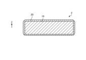
- FIG. 1 is a perspective view showing an example of a coated tool according to an embodiment.
- FIG. 2 is a side sectional view showing an example of the coated tool according to the embodiment.
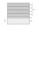
- FIG. 3 is a cross-sectional view showing an example of the coating layer according to the embodiment.
- FIG. 4 is a cross-sectional view showing an example of a Ta-containing laminate structure and a Mo-containing laminate structure that constitute the coating layer according to the embodiment.
- FIG. 5 is a cross-sectional view showing an example of the first compound layer and the second compound layer constituting the Ta-containing laminated structure.
- FIG. 6 is a cross-sectional view showing an example of the third compound layer and the fourth compound layer that constitute the Mo-containing laminated structure.
- FIG. 1 is a perspective view showing an example of a coated tool according to an embodiment.
- FIG. 2 is a side sectional view showing an example of the coated tool according to the embodiment.
- FIG. 3 is a cross-sectional view showing an example of the coating layer according to the
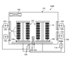
- FIG. 7 is a diagram schematically showing an example of a film forming apparatus for forming a coating layer on a substrate.
- FIG. 8 is a front view showing an example of the cutting tool according to the embodiment.
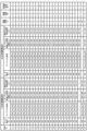
- FIG. 9 is a table showing manufacturing conditions for the coating layer formed on the substrate.
- FIG. 10 is a table showing the structure of the coating layer formed on the substrate.
- FIG. 11A shows sample No. 2 is a photograph showing the distribution of Ta in the cross section of Ta-containing laminated structures Nos. 4 to 15 and 19 to 21.
- FIG. 11B shows sample No. 2 is a graph showing the distribution of Ta in the cross section of Ta-containing laminated structures Nos. 4 to 15 and Nos. 19 to 21.
- FIG. 12A shows sample No.
- FIG. 2 is a photograph showing the distribution of Mo in the cross section of Mo-containing laminated structures Nos. 1 to 3, 7 to 12, 16 to 18, 22, and 23.
- FIG. 12B shows sample No. 2 is a graph showing the distribution of Mo in the cross sections of Mo-containing laminated structures Nos. 1 to 3, 7 to 12, 16 to 18, 22, and 23.
- FIG. 13 shows sample No. 1 ⁇ No. 27 is a table showing the results of a cutting test for No. 27 coated tools.
- Coated tools which have improved wear resistance by coating the surface of a base material such as cemented carbide, cermet, or ceramics with a coating layer, are known as tools used for cutting processes such as turning or milling. ing.
- FIG. 1 is a perspective view showing an example of a coated tool according to an embodiment.
- FIG. 2 is a side sectional view showing an example of the coated tool 1 according to the embodiment.
- the coated tool 1 according to the embodiment has a tip body 2.
- FIG. 1 is a perspective view showing an example of a coated tool according to an embodiment.
- FIG. 2 is a side sectional view showing an example of the coated tool 1 according to the embodiment.
- the coated tool 1 according to the embodiment has a tip body 2.
- FIG. 1 is a perspective view showing an example of a coated tool according to an embodiment.
- FIG. 2 is a side sectional view showing an example of the coated tool 1 according to the embodiment.
- the coated tool 1 according to the embodiment has a tip body 2.
- FIG. 1 is a perspective view showing an example of a coated tool according to an embodiment.
- FIG. 2 is a side sectional view showing an example of the coated tool 1 according to the embodiment.
- the coated tool 1 according to the embodiment has a tip body 2.
- Chip body 2 has, for example, a hexahedral shape in which the top surface and the bottom surface (the surface intersecting the Z axis shown in FIG. 1) are parallelograms.
- the cutting edge has a first surface (for example, an upper surface) and a second surface (for example, a side surface) connected to the first surface.
- the first surface functions as a "rake surface” that scoops up chips generated by cutting
- the second surface functions as a "relief surface.”
- a cutting blade is located on at least a portion of the ridgeline where the first surface and the second surface intersect, and the coated tool 1 cuts the workpiece by applying the cutting blade to the workpiece.
- a through hole 5 that vertically passes through the chip body 2 is located in the center of the chip body 2.
- a screw 75 for attaching the coated tool 1 to a holder 70, which will be described later, is inserted into the through hole 5 (see FIG. 8).
- the chip body 2 has a base 10 and a covering layer 20.
- the base body 10 is made of cemented carbide, for example.
- the cemented carbide contains W (tungsten), specifically, WC (tungsten carbide).
- the cemented carbide may contain Ni (nickel) or Co (cobalt).
- the base body 10 is made of a WC-based cemented carbide having WC particles as a hard phase component and Co as a main binder phase component.
- the base body 10 may be formed of cermet.
- the cermet contains, for example, Ti (titanium), specifically TiC (titanium carbide) or TiN (titanium nitride).
- the cermet may contain Ni or Co.
- the base body 10 may be formed of a cubic boron nitride sintered body containing cubic boron nitride (cBN) particles.
- the substrate 10 is not limited to cubic boron nitride (cBN) particles, but may also contain particles such as hexagonal boron nitride (hBN), rhombohedral boron nitride (rBN), or wurtzite boron nitride (wBN). good.
- the base body 10 may be made of ceramics. Ceramics contain, for example, oxidized Al 2 O 3 (aluminum oxide), such as ⁇ -Al 2 O 3 and ⁇ -Al 2 O 3 . Ceramics may contain other elements in aluminum oxide. For example, in addition to aluminum oxide, ceramics contain at least one of magnesium (Mg), calcium (Ca), strontium (Sr), silicon (Si), and a Group 3 element of the periodic table. Good too.
- aluminum oxide oxidized Al 2 O 3
- ceramics may contain other elements in aluminum oxide.
- ceramics contain at least one of magnesium (Mg), calcium (Ca), strontium (Sr), silicon (Si), and a Group 3 element of the periodic table. Good too.
- the coating layer 20 is coated on the base body 10 for the purpose of improving the wear resistance, heat resistance, etc. of the base body 10, for example.
- a covering layer 20 completely covers the substrate 10.
- the covering layer 20 is located at least on the base 10 .
- the coating layer 20 is located on the first surface (here, the upper surface) of the base 10, the first surface has high wear resistance and high heat resistance.
- the coating layer 20 is located on the second surface (here, the side surface) of the base 10, the second surface has high wear resistance and high heat resistance.
- FIG. 3 is a cross-sectional view showing an example of the coating layer 20 according to the embodiment.
- FIG. 4 is a cross-sectional view showing an example of a Ta-containing laminate structure and a Mo-containing laminate structure that constitute the coating layer 20 according to the embodiment.
- FIG. 5 is a cross-sectional view showing an example of the first compound layer and the second compound layer constituting the Ta-containing laminated structure.
- FIG. 6 is a cross-sectional view showing an example of the third compound layer and the fourth compound layer that constitute the Mo-containing laminated structure.
- the covering layer 20 includes a plurality of Ta-containing laminate structures 22 and a plurality of Mo-containing laminate structures 23 located on the intermediate layer 21.
- Each of the plurality of Ta-containing laminated structures 22 is a laminated structure containing at least Ta.
- Each of the plurality of Mo-containing laminated structures 23 is a laminated structure containing at least Mo.
- the plurality of Ta-containing laminate structures 22 and the plurality of Mo-containing laminate structures 23 may be alternately stacked within the coating layer 20.
- the residual stress between the Ta-containing laminate structure 22 and the Mo-containing laminate structure 23 can be reduced. Thereby, peeling or cracking between the Ta-containing laminate structure 22 and the Mo-containing laminate structure 23 can be reduced. Further, the effects of the Ta-containing laminated structure 22 and the Mo-containing laminated structure 23, which will be described later, can be improved. As a result, the life of the coated tool 1 can be extended.
- the average thickness of each of the plurality of Ta-containing laminate structures 22 and the plurality of Mo-containing laminate structures 23 may be 300 nm or more and 500 nm or less.
- the residual stress between the Ta-containing laminate structure 22 and the Mo-containing laminate structure 23 can be reduced. Thereby, peeling or cracking between the Ta-containing laminate structure 22 and the Mo-containing laminate structure 23 can be reduced. Further, the effects of the Ta-containing laminated structure 22 and the Mo-containing laminated structure 23, which will be described later, can be improved. As a result, the life of the coated tool 1 can be extended.
- An intermediate layer 21 may be located between the base body 10 and the covering layer 20. Specifically, the intermediate layer 21 is in contact with the upper surface of the base 10 on one surface (here, the lower surface), and in contact with the covering layer 20 (for example, the Ta-containing laminate structure 22) on the other surface (here, the upper surface). touches the bottom surface of
- the intermediate layer 21 has higher adhesion to the base 10 than the covering layer 20.
- metal elements having such characteristics include Zr, Hf, V, Nb, Ta, Cr, Mo, W, Al, Si, Y, and Ti.
- the intermediate layer 21 contains at least one metal element among the above metal elements.
- the intermediate layer 21 may contain Ti.
- Si is a metalloid element, in this specification, metalloid elements are also included in metal elements.
- the content rate of Ti in the intermediate layer 21 may be 1.5 atomic % or more.
- the Ti content in the intermediate layer 21 may be 2 atomic % or more.
- the intermediate layer 21 may contain components other than the above metal elements (Zr, Hf, V, Nb, Ta, Cr, Mo, W, Al, Si, Y, and Ti). However, from the viewpoint of adhesion to the base 10, the intermediate layer 21 may contain at least 95 atomic % or more of the above metal elements in total. The intermediate layer 21 may contain the above metal elements in a total amount of 98 atomic % or more. The proportion of the metal component in the intermediate layer 21 can be determined, for example, by analysis using an EDS (energy dispersive X-ray spectrometer) attached to a STEM (scanning transmission electron microscope).
- EDS energy dispersive X-ray spectrometer
- the intermediate layer 21 which has higher wettability with the substrate 10 than the coating layer 20, between the substrate 10 and the coating layer 20, the adhesion between the substrate 10 and the coating layer 20 can be improved. can. Since the intermediate layer 21 has high adhesion to the coating layer 20, peeling of the coating layer 20 from the intermediate layer 21 is unlikely to occur.
- the thickness of the intermediate layer 21 may be, for example, 0.1 nm or more and less than 20 nm.
- each of the plurality of Ta-containing laminated structures 22 includes a first compound layer 22a and a second compound layer 22b.
- the first compound layer 22a contains Ta in a first composition ratio.
- the second compound layer 22b contains Ta at a second composition ratio different from the first composition ratio. Note that one of the first composition ratio and the second composition ratio may be 0.
- each of the plurality of Ta-containing laminated structures 22 includes a first compound layer 22a containing Ta at a first composition ratio and a second compound layer 22a containing Ta at a second composition ratio different from the first composition ratio.
- the second compound layer 22b By including the second compound layer 22b, the thermal shock resistance, oxidation resistance, and hardness at high temperatures of the coating layer 20 can be improved. As a result, the life of the coated tool 1 can be extended.
- the first compound layer 22a and the second compound layer 22b may each contain Al, Ti, and Ta.
- the Ta content Ta(2) contained in the second compound layer 22b is Al(1) ⁇ Al(2), Ti(1) ⁇ Ti(2), and Ta(1)>Ta(2 ).
- Ta(2) may also be 0.
- Al(1), Ti(1), Ta(1), Al(2), Ti(2), and Ta(2) satisfy Al(1) ⁇ Al(2), Ti(1) ⁇ Ti(2) ), and when the relationship Ta(1)>Ta(2) is satisfied, the residual stress between the first compound layer 22a and the second compound layer 22b is reduced, and the first compound layer 22a And the hardness and adhesion of the second compound layer 22b can be maintained. Thereby, peeling or cracking between the first compound layer 22a and the second compound layer 22b can be reduced, and the strength of the coating layer 20 can be improved. As a result, the life of the coated tool 1 can be extended.
- the hardness and wear resistance of the coating layer 20 can be maintained.
- b and c satisfy the relationships of 0.3 ⁇ b ⁇ 0.5 and 0.02 ⁇ c ⁇ 0.2, the oxidation resistance of the coating layer 20 is maintained and the strength of the coating layer 20 at high temperatures is improved. can be improved. As a result, the life of the coated tool 1 can be extended.
- c of the Ta-containing compound contained in the first compound layer 22a may change continuously in the thickness direction of the first compound layer 22a.
- c of the Ta-containing compound contained in the second compound layer 22b may change continuously in the thickness direction of the second compound layer 22b.
- c for the Ta-containing compound contained in the first compound layer 22a may be maximum near the center of the distance in the thickness direction of the first compound layer 22a.
- c for the Ta-containing compound contained in the second compound layer 22b may be minimal near the center of the distance in the thickness direction of the second compound layer 22b.
- the residual stress between the first compound layer 22a and the second compound layer 22b can be further reduced. Thereby, peeling or cracking between the first compound layer 22a and the second compound layer 22b can be reduced. As a result, the life of the coated tool 1 can be extended.
- each of the plurality of Mo-containing laminated structures 23 includes a third compound layer 23a and a fourth compound layer 23b.
- the third compound layer 23a contains Mo at a third composition ratio.
- the fourth compound layer 23b contains Mo at a fourth composition ratio different from the third composition ratio.
- One of the third composition ratio and the fourth composition ratio may be zero.
- each of the plurality of Mo-containing laminated structures 23 includes a third compound layer 23a containing Mo at a third composition ratio, and a fourth compound layer 23a containing Mo at a fourth composition ratio different from the third composition ratio.
- the fourth compound layer 23b By including the fourth compound layer 23b, the toughness and strength of the covering layer 20 can be improved. Furthermore, the lubricity of the coating layer 20 can be maintained even at high temperatures. As a result, the life of the coated tool 1 can be extended.
- Each of the third compound layer 23a and the fourth compound layer 23b may contain Al, Cr, and Mo.
- the Mo content Mo(4) contained in the fourth compound layer 23b is Al(3) ⁇ Al(4), Cr(3)>Cr(4), and Mo(3)>Mo(4). ).
- Mo(4) may also be 0.
- Al(3), Cr(3), Mo(3), Al(4), Cr(4), and Mo(4) are Al(3) ⁇ Al(4), Cr(3)>Cr(4 ), and the relationship Mo(3)>Mo(4), the residual stress between the third compound layer 23a and the fourth compound layer 23b can be reduced. Thereby, peeling or cracking between the third compound layer 23a and the fourth compound layer 23b can be reduced. Furthermore, the lubricity of the coating layer 20 can be maintained even at high temperatures, and the thermal shock resistance, strength, oxidation resistance, and hardness at high temperatures of the coating layer 20 can be further improved. As a result, the life of the coated tool 1 can be extended.
- the hardness and wear resistance of the coating layer 20 can be maintained.
- e, f, and g satisfy the relationships of 0.2 ⁇ e ⁇ 0.45, 0.03 ⁇ f ⁇ 0.15, and 0.02 ⁇ g ⁇ 0.2, the coating layer at high temperature
- the thermal shock resistance, strength, and oxidation resistance of the coating layer 20 can be improved while maintaining the lubricity of the coating layer 20. As a result, the life of the coated tool 1 can be extended.
- g of the Mo-containing compound contained in the third compound layer 23a may change continuously in the thickness direction of the third compound layer 23a.
- g of the Mo-containing compound contained in the fourth compound layer 23b may change continuously in the thickness direction of the fourth compound layer 23b.
- g of the Mo-containing compound contained in the third compound layer 23a may be maximum near the center of the distance in the thickness direction of the third compound layer 23a.
- g of the Mo-containing compound contained in the fourth compound layer 23b may be minimal near the center of the distance in the thickness direction of the fourth compound layer 23b.
- the residual stress between the third compound layer 23a and the fourth compound layer 23b can be further reduced.
- peeling or cracking between the third compound layer 23a and the fourth compound layer 23b can be reduced.
- the life of the coated tool 1 can be extended.
- the average value of the thicknesses of the first compound layer 22a, the second compound layer 22b, the third compound layer 23a, and the fourth compound layer 23b may be 3 nm or more and 15 nm or less.
- the Ta-containing laminated structure 22 including the first compound layer 22a and the second compound layer 22b is a laminated structure of a plurality of layers having nanoscale thickness.
- the Mo-containing laminated structure 23 including the third compound layer 23a and the fourth compound layer 23b is a laminated structure of a plurality of layers having nanoscale thickness.
- FIG. 7 is a diagram schematically showing an example of a film forming apparatus for forming a coating layer on a substrate. Note that the method for manufacturing the coated tool 1 is not limited to the method shown below.
- a base body 10 having the shape of the coated tool 1 is produced using a conventionally known method.
- a coating layer 20 is formed on the surface of the base 10.
- a method for forming the coating layer 20 for example, a physical vapor deposition (PVD) method such as an ion plating method or a sputtering method can be used.
- PVD physical vapor deposition
- an arc ion plating film forming apparatus hereinafter referred to as an AIP apparatus 1000 as shown in FIG. 7 can be used, for example.
- the AIP device 1000 shown in FIG. 7 introduces a gas such as N 2 or Ar into a vacuum chamber 101 from a gas inlet 102, and creates a high temperature gap between a cathode electrode 103 and an anode electrode 104 arranged in the AIP device 1000.
- a voltage is applied to generate a gas plasma.
- Such plasma evaporates and ionizes the desired metal or ceramic from the target 105 to generate metal or ceramic ions in a high energy state.
- This ionized metal or ceramic is attached to the surface of the base 10 as a sample, and the surface of the base 10 is coated with the coating layer 20 .
- a plurality of substrates 10 may be set on the tower 107 and placed on the sample support stand 106.
- a plurality of sample support stands 106 (two sets in the figure) may be placed on a table (not shown).
- a heater 108 for heating the base 10 a gas exhaust port 109 for discharging gas out of the system, and a bias power supply 110 for applying a bias voltage to the base 10 are provided. .
- the target 105 may include, for example, one or more metal tantalum (Ta), metal molybdenum (Mo), a group 5 element or a group 6 element of the periodic table, Si, Y, and Ce.
- Ta metal tantalum
- Mo metal molybdenum
- a metal target containing each metal independently, an alloy target made of a composite of these, and a mixture target consisting of a powder or sintered body of carbide, nitride, or boride thereof can be used.
- the metal source is evaporated by arc discharge or glow discharge, and the metal of the metal source is ionized.
- nitrogen ( N2 ) gas as a nitrogen source and methane ( CH4 )/acetylene (carbon source) are ionized.
- the coating layer 20 is deposited on the surface of the substrate 10 by reacting with C 2 H 2 ) gas or oxygen (O 2 ) gas.
- the sample support stand 106 is controlled so that the distance from the position of the target 105 to the position of the base 10 is 160 mm or more, preferably 260 mm or more.
- a large number of highly straight lines of magnetic force are generated from the center of the surface of the target 105 toward the base 10, and the magnetic flux density near the base 10 is set to 0.2 to 0.8 mT (millitesla).
- Nitrogen gas may be introduced into the AIP apparatus 1000 as a reaction gas to create an atmospheric pressure of 2 to 10 Pa.
- the temperature of the substrate 10 is maintained at 300 to 500°C.
- a bias voltage of -50 to -200 V is applied to the base 10, and an arc discharge of 80 to 200 A is generated between the target 105 (cathode electrode 103) and the anode electrode 104.
- Metal is deposited on the base 10 while rotating and revolving the base 10.
- an electromagnetic coil or a permanent magnet as a magnetic field generation source is installed around the target 105, or a permanent magnet is placed inside the AIP device 1000, for example, in the center.
- the magnetic field can be controlled by adjusting the position of adjacent targets 105.
- the magnetic force is calculated by measuring the magnetic flux density at the position of the base 10 using a magnetic flux density meter.
- the magnetic flux density is expressed in the unit mT (millitesla).
- the distance from the position of the target 105 to the position of the base 10 represents the distance measured at the position where the base 10 is closest to the target 105 and the distance where the base 10 is farthest from the target 105.
- the rotation speed of the sample is set to the period in which the substrate 10 approaches the target 105 at each position on the substrate 10 as shown in FIG.
- the period of the difference in the composition of heavy metals and light metals in the thickness direction of 20 can be adjusted.
- the rotational speeds of the base 10 and the sample support 106 may be adjusted to have a period of 2 to 20 rpm (rotations per minute).
- each of the sample supports 106 on which the substrate 10 is placed rotates while the tower 107 rotates, and the table may also be rotated so that the plurality of sample supports 106 revolve.
- the thickness of each compound layer constituting the Ta-containing laminated structure 22 and the Mo-containing laminated structure 23 can be controlled.
- the time or distance that metal ions fly from the target 105 to the base 10 can be adjusted. Thereby, it is also possible to differentiate the compositions of heavy metal components and light metal components during film formation.
- the base body 10 is arranged so that the base body 10 approaches and faces the target 105, heavy metal components from the target 105 will fly straight to the base body 10, and the amount of heavy metals will be larger than that of light metals. It is deposited on the substrate 10.
- the base body 10 is arranged so that the base body 10 is away from the target 105 and does not face the target 105, it is thought that the amount of heavy metal components deposited decreases because the light metal components go around and are deposited on the base body 10.
- FIG. 8 is a front view showing an example of the cutting tool according to the embodiment.
- the cutting tool 100 includes a covered tool 1 and a holder 70 for fixing the covered tool 1.
- the holder 70 is a rod-shaped member that extends from a first end (upper end in FIG. 8) to a second end (lower end in FIG. 8).
- the holder 70 is made of steel or cast iron, for example. In particular, among these materials, steel with high toughness is sometimes used.
- the holder 70 has a pocket 73 at the first end.
- the pocket 73 is a portion on which the coated tool 1 is mounted, and has a seating surface that intersects with the rotational direction of the workpiece, and a restraining side surface that is inclined with respect to the seating surface.
- the seating surface is provided with a screw hole into which a screw 75 (described later) is screwed.
- the covered tool 1 is located in the pocket 73 of the holder 70 and is attached to the holder 70 by screws 75. That is, the screw 75 is inserted into the through hole 5 of the covered tool 1, and the tip of the screw 75 is inserted into a screw hole formed in the seating surface of the pocket 73, so that the screw portions are screwed together. Thereby, the coated tool 1 is attached to the holder 70 such that the cutting edge portion 3 protrudes outward from the holder 70.
- a cutting tool used for so-called turning is exemplified.
- turning processing include inner diameter processing, outer diameter processing, and grooving.
- the cutting tool is not limited to those used for turning.
- the coated tool 1 may be used as a cutting tool used for milling.
- Cutting tools used for milling include, for example, milling cutters such as flat milling cutters, face milling cutters, side milling cutters, and groove milling cutters, and end mills such as single-flute end mills, multi-flute end mills, tapered-flute end mills, and ball end mills. Examples include.
- FIG. 9 is a table showing manufacturing conditions for the coating layer formed on the substrate.
- FIG. 10 is a table showing the structure of the coating layer formed on the substrate.
- FIG. 11A shows sample No. 2 is a photograph showing the distribution of Ta in the cross section of Ta-containing laminated structures Nos. 4 to 15 and 19 to 21.
- FIG. 11B shows sample No. 2 is a graph showing the distribution of Ta in the cross section of Ta-containing laminated structures Nos. 4 to 15 and Nos. 19 to 21.
- FIG. 12A shows sample No. 2 is a photograph showing the distribution of Mo in the cross section of Mo-containing laminated structures Nos.
- FIG. 12B shows sample No. 2 is a graph showing the distribution of Mo in the cross sections of Mo-containing laminated structures Nos. 1 to 3, 7 to 12, 16 to 18, 22, and 23.
- FIG. 13 shows sample No. 1 ⁇ No. 27 is a table showing the results of a cutting test for No. 27 coated tools.
- FIG. 11A The photograph shown in FIG. 11A was taken using an energy dispersive spectrometer (EDS) for sample No. These are photographs taken of cross sections of Ta-containing laminated structures Nos. 4 to 15 and 19 to 21.
- the photograph shown in FIG. 12A was taken using EDS for sample No. 1-3, 7-12, 16-18, 22, and 23 are photographs taken of cross sections of Mo-containing laminated structures.
- the horizontal direction in FIGS. 11A and 12A is a direction perpendicular to the surface of the base.
- the vertical direction in FIGS. 11A and 12A is the direction along the surface of the base.
- the horizontal axis indicates the distance (nm) in the direction perpendicular to the surface of the substrate, and the vertical axis indicates the value of c of the Ta-containing compound contained in the Ta-containing laminate structure.
- the horizontal axis indicates the distance (nm) in the direction perpendicular to the surface of the substrate, and the vertical axis indicates the g value of the Mo-containing compound contained in the Mo-containing laminate structure.
- sample No. 1 ⁇ No. Twenty-seven coated tools were made.
- a coating layer was formed on the surface of the substrate under the following conditions.
- the distance (mm) between the target and the substrate was varied within the range of values shown in FIG. 9 by rotation of the sample support.
- the magnetic flux density (mT) near the substrate also varied within the range of values shown in FIG.
- each of the number of Ta-containing laminated structures, the number of Mo-containing laminated structures, the number of Ta-containing single-layer structures, and the number of Mo-containing single-layer structures is determined by the number of laminations (times) as shown in FIG. ).
- Each of the Ta-containing laminate structure, Mo-containing laminate structure, Ta-containing single-layer structure, and Mo-containing single-layer structure was formed on the surface of the substrate during the lamination time (minutes) shown in FIG. .
- Sample No. 1 ⁇ No. No. 23 coated tools correspond to embodiments of the present disclosure.
- Sample No. 24 ⁇ No. Coated tool No. 27 corresponds to a comparative example of the present disclosure.
- Sample No. For coated tool No. 26 the Ta-containing laminate structure was composed of a first compound layer and a second compound layer.
- the coating layer did not include either the Ta-containing laminate structure or the Mo-containing laminate structure, and had a Ta-containing single-layer structure having the same composition as the composition of each target as shown in FIG. The structure contained a Mo-containing monolayer structure.
- Each of the first compound layer and the second compound layer contained a Ta- containing compound represented by ( AlaTibTac ) N .
- a, b, and c were the values shown in FIG.
- the values of a, b, and c shown in FIG. 10 are averages for the Ta-containing compounds contained in the plurality of first compound layers or the plurality of second compound layers contained in the Ta-containing laminated structure. It was a value.
- the average composition of the Ta-containing laminate structure composed of the first compound layer and the second compound layer matched the composition of the target for producing the Ta-containing laminate structure shown in FIG.
- Each of the third compound layer and the fourth compound layer contained a Mo-containing compound represented by (Al d Cre Si f Mo g ).
- d, e, f, and g were the values shown in FIG.
- the values of d, e, f, and g shown in FIG. was the average value.
- the average composition of the Mo-containing laminate structure composed of the third compound layer and the fourth compound matched the composition of the target for manufacturing the Mo-containing laminate structure shown in FIG.
- each of the Ta-containing laminate structure and the Mo-containing laminate structure was the thickness (nm) of each laminate structure as shown in FIG. Sample No. For coated tool No. 25, the thickness of the Mo-containing laminate structure was 4000 nm as shown in FIG. Sample No. For coated tool No. 26, the thickness of the Ta-containing laminate structure was 4000 nm as shown in FIG. Sample No. For coated tool No. 27, the thickness of each of the Ta-containing single layer structure and the Mo-containing single layer structure was 400 nm as shown in FIG.
- Sample No. 1 ⁇ No. For the No. 24 coated tool, the average thickness of the first compound layer, second compound layer, third compound layer, and fourth compound layer is the average thickness of the compound layer as shown in FIG. It was the value of diameter (nm).
- Sample No. For coated tools No. 25 the average thickness of the third and fourth compound layers was 8 nm as shown in FIG.
- Sample No. for No. 26 coated tools, the average thickness of the first compound layer and the second compound layer was 8 nm as shown in FIG. Sample No. Regarding the coated tool No. 27, the coating layer did not include any of the first compound layer, the second compound layer, the third compound layer, and the fourth compound layer.
- the Ta-containing laminated structure includes a plurality of first compound layers composed of a Ta-containing compound having a relatively high value of c and a relatively high value of c. It was confirmed that a plurality of second compound layers composed of a low Ta-containing compound were included. That is, it was confirmed that in the Ta-containing laminated structure, a plurality of first compound layers and a plurality of second compound layers were alternately laminated.
- the value of c of the Ta-containing compound contained in the first compound layer is continuous with respect to the distance from the surface of the substrate in the direction of the thickness of the first compound layer, that is, in the direction perpendicular to the surface of the substrate.
- the value of c of the Ta-containing compound contained in the second compound layer is continuous with respect to the distance from the surface of the substrate in the direction of the thickness of the second compound layer, that is, in the direction perpendicular to the surface of the substrate.
- the Mo-containing laminate structure includes a plurality of third compounds composed of Mo-containing compounds having relatively high values of g. It was confirmed that the fourth compound layer was composed of a Mo-containing compound having a relatively low value of g. That is, it was confirmed that in the Mo-containing laminated structure, a plurality of third compound layers and a plurality of fourth compound layers were alternately laminated.
- the value of g of the Mo-containing compound contained in the third compound layer is continuous with respect to the distance from the surface of the substrate in the direction of the thickness of the third compound layer, that is, in the direction perpendicular to the surface of the substrate.
- the value of g of the Mo-containing compound contained in the fourth compound layer is continuous with respect to the distance from the surface of the substrate in the direction of the thickness of the fourth compound layer, that is, in the direction perpendicular to the surface of the substrate.
- Cutting method Shoulder milling using a square material with a size of 170 mm x 260 mm x 110 mm (2) Work material: SC ⁇ 440 (3) Cutting speed Vc: low speed (160m/min) and high speed (300m/min) (4) Feed amount per tooth fz: 0.12mm/t (5) Axial cutting depth ap: 2mm (6) Radial cutting depth ae: 63mm (7) Machining form: Dry and wet (8) Evaluation method: Milling the workpiece under the above conditions, and measuring the time when the Vb wear width of the tool flank reaches 0.1 mm is the point at which the coated tool I judged it to be the end of its lifespan.
- FIG. 13 shows sample No. 1 ⁇ No. 27 is a table showing the results of a cutting test for No. 27 coated tools.
- At least the coating layer includes a plurality of Ta-containing laminate structures and a plurality of Mo-containing laminate structures, and each of the plurality of Ta-containing laminate structures includes a first layer containing Ta at a first composition ratio. and a second compound layer containing Ta at a second composition ratio different from the first composition ratio, and each of the plurality of Mo-containing laminate structures contains Mo at a third composition ratio.
- each of the first compound layer and the second compound layer contains Al, Ti, and Ta, and as shown in FIG.
- b of the first compound layer, c of the first compound layer, a of the second compound layer, b of the second compound layer, and c of the second compound layer are such that a of the first compound layer ⁇ second compound layer a, b of the first compound layer ⁇ b of the second compound layer, and c of the first compound layer>c of the second compound layer, and the third compound layer and the third compound layer
- Each of the four compound layers contains Al, Cr, and Mo, and d of the third compound layer, e of the third compound layer, g of the third compound layer, and g of the fourth compound layer.
- d, e of the fourth compound layer, and g of the fourth compound layer are such that d of the third compound layer ⁇ d of the fourth compound layer, e of the third compound layer>e of the fourth compound layer. It was confirmed that the life of the coated tool can be further extended when the relationship of g of the third compound layer>g of the fourth compound layer is satisfied.
- sample No. 1 ⁇ No. Among the 18 coated tools, sample No. 3 and no. 7 ⁇ No.
- the service life of the coated tool No. 12 was the same for sample No. 12 in both dry and wet machining, and in both low-speed and high-speed machining. 1.No. 2.No. 4 ⁇ No. 6, and no. 13 ⁇ No.
- the lifespan was equal to or longer than that of No. 18 coated tools.
- the coated tool according to the embodiment includes a base body (for example, base body 10) and a coating layer located on the base body (for example, coating layer 20). Be prepared.
- the coating layer includes a plurality of Ta-containing laminate structures (for example, the Ta-containing laminate structure 22) and a plurality of Mo-containing laminate structures (for example, the Mo-containing laminate structure 23).
- Each of the plurality of Ta-containing laminated structures includes a first compound layer (for example, the first compound layer 22a) containing Ta at a first composition ratio, and a second composition that is different from the first composition ratio.
- a second compound layer (for example, the second compound layer 22b) containing Ta at a certain ratio.
- Each of the plurality of Mo-containing laminated structures includes a third compound layer (for example, the third compound layer 23a) containing Mo at a third composition ratio, and a fourth composition different from the third composition ratio.
- a fourth compound layer (for example, the fourth compound layer 23b) containing Mo in the ratio.
- the life of the tool can be extended.
- a coated tool according to the present disclosure includes, for example, a rod-shaped main body having a rotating shaft and extending from a first end to a second end, a cutting blade located at the first end of the main body, and a second end of the main body from the cutting blade. It may have a groove extending spirally toward the side.
- each of the containing laminated structures includes a first compound layer containing Ta at a first composition ratio, and a second compound layer containing Ta at a second composition ratio different from the first composition ratio.
- each of the plurality of Mo-containing laminated structures includes a third compound layer containing Mo at a third composition ratio, and a third compound layer containing Mo at a fourth composition ratio different from the third composition ratio.
- a coated tool comprising a compound layer of 4.
- Additional Note (2) The coated tool according to Additional Note (1), wherein the plurality of Ta-containing laminate structures and the plurality of Mo-containing laminate structures are alternately laminated within the coating layer.
- the Al content Al(2), the Ti content Ti(2) contained in the second compound layer, and the Ta content Ta(2) contained in the second compound layer are:
- the coated tool according to appendix (1) or (2) which has the following relationships: Al(1) ⁇ Al(2), Ti(1) ⁇ Ti(2), and Ta(1)>Ta(2).
- Each of the third compound layer and the fourth compound layer contains Al, Cr, and Mo, and the content of Al contained in the third compound layer is Al( 3), the content of Cr contained in the third compound layer Cr(3), the content of Mo contained in the third compound layer Mo(3), the content of Mo contained in the fourth compound layer
- the Al content Al(4), the Cr content Cr(4) contained in the fourth compound layer, and the Mo content Mo(4) contained in the fourth compound layer are: Described in any one of supplementary notes (1) to (4), having the relationships Al(3) ⁇ Al(4), Cr(3)>Cr(4), and Mo(3)>Mo(4). coated tools.
- the coated tool according to any one of (5).
- the average thickness of each of the plurality of Ta-containing laminate structures and the plurality of Mo-containing laminate structures is 300 nm or more and 500 nm or less, and The coated tool according to any one of appendixes (1) to (6), wherein the compound layer, the third compound layer, and the fourth compound layer have an average thickness of 3 nm or more and 15 nm or less.
Landscapes
- Chemical & Material Sciences (AREA)
- Engineering & Computer Science (AREA)
- Mechanical Engineering (AREA)
- Chemical Kinetics & Catalysis (AREA)
- Materials Engineering (AREA)
- Metallurgy (AREA)
- Organic Chemistry (AREA)
- Cutting Tools, Boring Holders, And Turrets (AREA)
- Physical Vapour Deposition (AREA)
Abstract
本開示による被覆工具は、基体と、基体の上に位置する被覆層とを備える。被覆層は、複数のTa含有積層構造体と、複数のMo含有積層構造体とを含む。複数のTa含有積層構造体の各々は、第1の組成比でTaを含有する第1の化合物層と、第1の組成比と異なる第2の組成比でTaを含有する第2の化合物層とを含む。複数のMo含有積層構造体の各々は、第3の組成比でMoを含有する第3の化合物層と、第3の組成比と異なる第4の組成比でMoを含有する第4の化合物層とを含む。
Description
本開示は、被覆工具および切削工具に関する。
旋削加工または転削加工等の切削加工に用いられる工具として、超硬合金、サーメット、またはセラミックス等の基体の表面を被覆層でコーティングすることによって耐摩耗性等を向上させた被覆工具が知られている。
本開示の一態様による被覆工具は、基体と、基体の上に位置する被覆層とを備える。被覆層は、複数のTa含有積層構造体と、複数のMo含有積層構造体とを含む。複数のTa含有積層構造体の各々は、第1の組成比でTaを含有する第1の化合物層と、第1の組成比と異なる第2の組成比でTaを含有する第2の化合物層とを含む。複数のMo含有積層構造体の各々は、第3の組成比でMoを含有する第3の化合物層と、第3の組成比と異なる第4の組成比でMoを含有する第4の化合物層とを含む。
以下に、本開示による被覆工具および切削工具を実施するための形態(以下、「実施形態」と記載する)について図面を参照しつつ詳細に説明する。この実施形態により本開示による被覆工具および切削工具が限定されるものではない。各実施形態は、処理内容を矛盾させない範囲で適宜組み合わせることが可能である。以下の各実施形態において同一の部位には同一の符号を付し、重複する説明は省略される。
以下に示す実施形態では、「一定」、「直交」、「垂直」あるいは「平行」といった表現が用いられる場合があるが、これらの表現は、厳密に「一定」、「直交」、「垂直」あるいは「平行」であることを要しない。すなわち、上記した各表現は、例えば製造精度、または設置精度などのずれを許容するものとする。
旋削加工または転削加工等の切削加工に用いられる工具として、超硬合金、サーメット、またはセラミックス等の基体の表面を被覆層でコーティングすることによって耐摩耗性等を向上させた被覆工具が知られている。
上述した従来技術には、工具の寿命を延ばすという点で更なる改善の余地がある。
そこで、上述の問題点を克服し、工具の寿命を延ばすことができる技術の実現が期待されている。
<被覆工具>
図1は、実施形態に係る被覆工具の一例を示す斜視図である。図2は、実施形態に係る被覆工具1の一例を示す側断面図である。図1に示すように、実施形態に係る被覆工具1は、チップ本体2を有する。
図1は、実施形態に係る被覆工具の一例を示す斜視図である。図2は、実施形態に係る被覆工具1の一例を示す側断面図である。図1に示すように、実施形態に係る被覆工具1は、チップ本体2を有する。
(チップ本体2)
チップ本体2は、たとえば、上面および下面(図1に示すZ軸と交わる面)の形状が平行四辺形である六面体形状を有する。
チップ本体2は、たとえば、上面および下面(図1に示すZ軸と交わる面)の形状が平行四辺形である六面体形状を有する。
チップ本体2の1つのコーナー部は、切刃部として機能する。切刃部は、第1面(たとえば上面)と、第1面に連接する第2面(たとえば側面)とを有する。実施形態において、第1面は切削により生じた切屑をすくい取る「すくい面」として機能し、第2面は「逃げ面」として機能する。第1面および第2面が交わる稜線の少なくとも一部には、切刃が位置しており、被覆工具1は、かかる切刃を被削材に当てることによって被削材を切削する。
チップ本体2の中央部には、チップ本体2を上下に貫通する貫通孔5が位置する。貫通孔5には、後述するホルダ70に被覆工具1を取り付けるためのネジ75が挿入される(図8参照)。
図2に示すように、チップ本体2は、基体10と、被覆層20とを有する。
(基体10)
基体10は、たとえば超硬合金で形成される。超硬合金は、W(タングステン)、具体的には、WC(炭化タングステン)を含有する。超硬合金は、Ni(ニッケル)またはCo(コバルト)を含有していてもよい。具体的には、基体10は、WC粒子を硬質相成分とし、Coを結合相の主成分とするWC基超硬合金からなる。
基体10は、たとえば超硬合金で形成される。超硬合金は、W(タングステン)、具体的には、WC(炭化タングステン)を含有する。超硬合金は、Ni(ニッケル)またはCo(コバルト)を含有していてもよい。具体的には、基体10は、WC粒子を硬質相成分とし、Coを結合相の主成分とするWC基超硬合金からなる。
基体10は、サーメットで形成されてもよい。サーメットは、たとえばTi(チタン)、具体的には、TiC(炭化チタン)またはTiN(窒化チタン)を含有する。サーメットは、NiまたはCoを含有していてもよい。
基体10は、立方晶窒化硼素(cBN)粒子を含有する立方晶窒化硼素質焼結体で形成されてもよい。基体10は、立方晶窒化硼素(cBN)粒子に限らず、六方晶窒化硼素(hBN)、菱面体晶窒化硼素(rBN)、またはウルツ鉱窒化硼素(wBN)等の粒子を含有していてもよい。
基体10は、セラミックスで形成されてもよい。セラミックスは、たとえば酸化Al2O3(酸化アルミニウム)、例えば、κ-Al2O3及びα-Al2O3を含有する。セラミックスは、酸化アルミニウムに他の元素を含有していてもよい。例えば、セラミックスは、酸化アルミニウムに加えて、マグネシウム(Mg)、カルシウム(Ca)、ストロンチウム(Sr)、珪素(Si)及び周期律表の第3族元素のうち、少なくとも1つを含有していてもよい。
(被覆層20)
被覆層20は、例えば、基体10の耐摩耗性、および耐熱性等を向上させることを目的として基体10に被覆される。図2の例では、被覆層20が基体10を全体的に被覆している。被覆層20は、少なくとも基体10の上に位置していればよい。被覆層20が基体10の第1面(ここでは、上面)に位置する場合、第1面の耐摩耗性、および耐熱性が高い。被覆層20が基体10の第2面(ここでは、側面)に位置する場合、第2面の耐摩耗性、および耐熱性が高い。
被覆層20は、例えば、基体10の耐摩耗性、および耐熱性等を向上させることを目的として基体10に被覆される。図2の例では、被覆層20が基体10を全体的に被覆している。被覆層20は、少なくとも基体10の上に位置していればよい。被覆層20が基体10の第1面(ここでは、上面)に位置する場合、第1面の耐摩耗性、および耐熱性が高い。被覆層20が基体10の第2面(ここでは、側面)に位置する場合、第2面の耐摩耗性、および耐熱性が高い。
ここで、被覆層20の具体的な構成について図3、図4、図5、および図6を参照して説明する。図3は、実施形態に係る被覆層20の一例を示す断面図である。図4は、実施形態に係る被覆層20を構成するTa含有積層構造体およびMo含有積層構造体の一例を示す断面図である。図5は、Ta含有積層構造体を構成する第1の化合物層および第2の化合物層の一例を示す断面図である。図6は、Mo含有積層構造体を構成する第3の化合物層および第4の化合物層の一例を示す断面図である。
図3に示すように、被覆層20は、中間層21の上に位置する複数のTa含有積層構造体22と、複数のMo含有積層構造体23とを含む。複数のTa含有積層構造体22の各々は、少なくともTaを含有する積層構造体である。複数のMo含有積層構造体23の各々は、少なくともMoを含有する積層構造体である。
図3に示すように、複数のTa含有積層構造体22および複数のMo含有積層構造体23は、被覆層20内において交互に積層されることがある。
この場合には、Ta含有積層構造体22とMo含有積層構造体23との間の残留応力を低減することができる。それにより、Ta含有積層構造体22とMo含有積層構造体23との間の剥離またはクラックを低減することができる。また、後述するようなTa含有積層構造体22およびMo含有積層構造体23の効果を向上させることができる。その結果、被覆工具1の寿命を延ばすことができる。
複数のTa含有積層構造体22および複数のMo含有積層構造体23の各々の厚さの平均値は、300nm以上500nm以下であることがある。
この場合には、Ta含有積層構造体22とMo含有積層構造体23との間の残留応力を低減することができる。それにより、Ta含有積層構造体22とMo含有積層構造体23との間の剥離またはクラックを低減することができる。また、後述するようなTa含有積層構造体22およびMo含有積層構造体23の効果を向上させることができる。その結果、被覆工具1の寿命を延ばすことができる。
(中間層21)
基体10と被覆層20との間には、中間層21が位置していてもよい。具体的には、中間層21は、一方の面(ここでは下面)において基体10の上面に接し、且つ、他方の面(ここでは上面)において被覆層20(例えば、Ta含有積層構造体22)の下面に接する。
基体10と被覆層20との間には、中間層21が位置していてもよい。具体的には、中間層21は、一方の面(ここでは下面)において基体10の上面に接し、且つ、他方の面(ここでは上面)において被覆層20(例えば、Ta含有積層構造体22)の下面に接する。
中間層21は、基体10との密着性が被覆層20と比べて高い。このような特性を有する金属元素としては、たとえば、Zr、Hf、V、Nb、Ta、Cr、Mo、W、Al、Si、Y、およびTiが挙げられる。中間層21は、上記金属元素のうち少なくとも1種以上の金属元素を含有する。たとえば、中間層21は、Tiを含有していても良い。Siは、半金属元素であるが、本明細書においては、半金属元素も金属元素に含まれるものとする。
中間層21がTiを含有する場合、中間層21におけるTiの含有率は、1.5原子%以上であってもよい。たとえば、中間層21におけるTiの含有率は、2原子%以上であってもよい。
中間層21は、上記金属元素(Zr、Hf、V、Nb、Ta、Cr、Mo、W、Al、Si、Y、およびTi)以外の成分を含有していてもよい。ただし、基体10との密着性の観点から、中間層21は、上記金属元素を合量で少なくとも95原子%以上含有していてもよい。中間層21は、上記金属元素を合量で98原子%以上含有してもよい。中間層21における金属成分の割合は、たとえば、STEM(走査透過電子顕微鏡)に付属しているEDS(エネルギー分散型X線分光器)を用いた分析により特定可能である。
このように、基体10との濡れ性が被覆層20と比べて高い中間層21を基体10と被覆層20との間に設けることにより、基体10および被覆層20の密着性を向上させることができる。中間層21は、被覆層20との密着性も高いため、被覆層20が中間層21から剥離するといったことも生じにくい。
中間層21の厚みは、たとえば0.1nm以上、20nm未満であってもよい。
(Ta含有積層構造体22)
図4に示すように、複数のTa含有積層構造体22の各々は、第1の化合物層22aと、第2の化合物層22bとを含む。第1の化合物層22aは、第1の組成比でTaを含有する。第2の化合物層22bは、第1の組成比と異なる第2の組成比でTaを含有する。なお、第1の組成比および第2の組成比の一方は、0であることもある。
図4に示すように、複数のTa含有積層構造体22の各々は、第1の化合物層22aと、第2の化合物層22bとを含む。第1の化合物層22aは、第1の組成比でTaを含有する。第2の化合物層22bは、第1の組成比と異なる第2の組成比でTaを含有する。なお、第1の組成比および第2の組成比の一方は、0であることもある。
このように、複数のTa含有積層構造体22の各々が、第1の組成比でTaを含有する第1の化合物層22aと、第1の組成比と異なる第2の組成比でTaを含有する第2の化合物層22bとを含むことによって、被覆層20の耐熱衝撃性、耐酸化性、および高温における硬度を向上させることができる。その結果、被覆工具1の寿命を延ばすことができる。
第1の化合物層22aおよび第2の化合物層22bの各々は、Alと、Tiと、Taとを含有してもよい。この場合には、第1の化合物層22aに含有されるAlの含有率Al(1)、第1の化合物層22aに含有されるTiの含有率Ti(1)、第1の化合物層22aに含有されるTaの含有率Ta(1)、第2の化合物層22bに含有されるAlの含有率Al(2)、第2の化合物層22bに含有されるTiの含有率Ti(2)、および第2の化合物層22bに含有されるTaの含有率Ta(2)は、Al(1)<Al(2)、Ti(1)<Ti(2)、およびTa(1)>Ta(2)の関係を有することがある。Ta(2)は、0であることもある。
Al(1)、Ti(1)、Ta(1)、Al(2)、Ti(2)、およびTa(2)が、Al(1)<Al(2)、Ti(1)<Ti(2)、およびTa(1)>Ta(2)の関係を有する場合には、第1の化合物層22aと第2の化合物層22bとの間の残留応力を低減すると共に、第1の化合物層22aおよび第2の化合物層22bの硬度および密着性を維持することができる。それにより、第1の化合物層22aと第2の化合物層22bとの間の剥離またはクラックを低減すると共に被覆層20の強度を向上させることができる。その結果、被覆工具1の寿命を延ばすことができる。
第1の化合物層22aおよび第2の化合物層22bの各々は、式
(AlaTibTac)N・・・(1)
(式中、a、b、およびcは、0.35≦a≦0.65、0.3≦b≦0.5、0.02≦c≦0.2、およびa+b+c=1の関係を満たす)
によって表されるTa含有化合物を含んでもよい。
(AlaTibTac)N・・・(1)
(式中、a、b、およびcは、0.35≦a≦0.65、0.3≦b≦0.5、0.02≦c≦0.2、およびa+b+c=1の関係を満たす)
によって表されるTa含有化合物を含んでもよい。
aが、0.35≦a≦0.65の関係を満たす場合には、被覆層20の硬度および耐摩耗性を維持することができる。bおよびcが、0.3≦b≦0.5および0.02≦c≦0.2の関係を満たす場合には、被覆層20の耐酸化性を維持すると共に高温における被覆層20の強度を向上させることができる。その結果、被覆工具1の寿命を延ばすことができる。
図5に示すように、第1の化合物層22aに含まれるTa含有化合物についてのcは、第1の化合物層22aの厚さの方向において連続的に変化してもよい。第2の化合物層22bに含まれるTa含有化合物についてのcは、第2の化合物層22bの厚さの方向において連続的に変化してもよい。例えば、図5に示すように、第1の化合物層22aに含まれるTa含有化合物についてのcは、第1の化合物層22aの厚さの方向における距離の中央付近で極大であってもよい。第2の化合物層22bに含まれるTa含有化合物についてのcは、第2の化合物層22bの厚さの方向における距離の中央付近で極小であってもよい。
この場合には、第1の化合物層22aと第2の化合物層22bとの間の残留応力をさらに低減することができる。それにより、第1の化合物層22aと第2の化合物層22bとの間の剥離またはクラックを低減することができる。その結果、被覆工具1の寿命を延ばすことができる。
(Mo含有積層構造体23)
図4に示すように、複数のMo含有積層構造体23の各々は、第3の化合物層23aと、第4の化合物層23bとを含む。第3の化合物層23aは、第3の組成比でMoを含有する。第4の化合物層23bは、第3の組成比と異なる第4の組成比でMoを含有する。第3の組成比および第4の組成比の一方は、0であることもある。
図4に示すように、複数のMo含有積層構造体23の各々は、第3の化合物層23aと、第4の化合物層23bとを含む。第3の化合物層23aは、第3の組成比でMoを含有する。第4の化合物層23bは、第3の組成比と異なる第4の組成比でMoを含有する。第3の組成比および第4の組成比の一方は、0であることもある。
このように、複数のMo含有積層構造体23の各々が、第3の組成比でMoを含有する第3の化合物層23aと、第3の組成比と異なる第4の組成比でMoを含有する第4の化合物層23bとを含むことによって、被覆層20の靭性および強度を向上させることができる。また、高温においても被覆層20の潤滑性を維持することができる。その結果、被覆工具1の寿命を延ばすことができる。
第3の化合物層23aおよび第4の化合物層23bの各々は、Alと、Crと、Moとを含有してもよい。この場合には、第3の化合物層23aに含有されるAlの含有率Al(3)、第3の化合物層23aに含有されるCrの含有率Cr(3)、第3の化合物層23aに含有されるMoの含有率Mo(3)、第4の化合物層23bに含有されるAlの含有率Al(4)、第4の化合物層23bに含有されるCrの含有率Cr(4)、および第4の化合物層23bに含有されるMoの含有率Mo(4)は、Al(3)<Al(4)、Cr(3)>Cr(4)、およびMo(3)>Mo(4)の関係を有することがある。Mo(4)は、0であることもある。
Al(3)、Cr(3)、Mo(3)、Al(4)、Cr(4)、およびMo(4)が、Al(3)<Al(4)、Cr(3)>Cr(4)、およびMo(3)>Mo(4)の関係を有する場合には、第3の化合物層23aと第4の化合物層23bとの間の残留応力を低減することができる。それにより、第3の化合物層23aと第4の化合物層23bとの間の剥離またはクラックを低減することができる。また、高温においても被覆層20の潤滑性を維持し、被覆層20の耐熱衝撃性、強度、耐酸化性、および高温における硬度をさらに向上させることができる。その結果、被覆工具1の寿命を延ばすことができる。
第3の化合物層23aおよび第4の化合物層23bの各々は、式
(AldCreSifMog)N・・・(2)
(式中、d、e、f、およびgは、0.35≦d≦0.65、0.2≦e≦0.45、0.03≦f≦0.15、0.02≦g≦0.2、およびd+e+f+g=1の関係を満たす)
によって表されるMo含有化合物を含んでもよい。
(AldCreSifMog)N・・・(2)
(式中、d、e、f、およびgは、0.35≦d≦0.65、0.2≦e≦0.45、0.03≦f≦0.15、0.02≦g≦0.2、およびd+e+f+g=1の関係を満たす)
によって表されるMo含有化合物を含んでもよい。
dが、0.35≦d≦0.65の関係を満たす場合には、被覆層20の硬度および耐摩耗性を維持することができる。e、f、およびgが、0.2≦e≦0.45、0.03≦f≦0.15、および0.02≦g≦0.2の関係を満たす場合には、高温における被覆層20の潤滑性を維持すると共に被覆層20の耐熱衝撃性、強度、および耐酸化性を向上させることができる。その結果、被覆工具1の寿命を延ばすことができる。
図6に示すように、第3の化合物層23aに含まれるMo含有化合物についてのgは、第3の化合物層23aの厚さの方向において連続的に変化してもよい。第4の化合物層23bに含まれるMo含有化合物についてのgは、第4の化合物層23bの厚さの方向において連続的に変化してもよい。例えば、図6に示すように、第3の化合物層23aに含まれるMo含有化合物についてのgは、第3の化合物層23aの厚さの方向における距離の中央付近で極大であってもよい。第4の化合物層23bに含まれるMo含有化合物についてのgは、第4の化合物層23bの厚さの方向における距離の中央付近で極小であってもよい。
この場合には、第3の化合物層23aと第4の化合物層23bとの間の残留応力をさらに低減することができる。それにより、第3の化合物層23aと第4の化合物層23bとの間の剥離またはクラックを低減することができる。その結果、被覆工具1の寿命を延ばすことができる。
第1の化合物層22a、第2の化合物層22b、第3の化合物層23a、および第4の化合物層23bの厚さの平均値は、3nm以上15nm以下であることがある。
この場合には、第1の化合物層22aおよび第2の化合物層22bを含むTa含有積層構造体22は、ナノスケールの厚さを有する複数の層の積層構造体である。第3の化合物層23aおよび第4の化合物層23bを含むMo含有積層構造体23は、ナノスケールの厚さを有する複数の層の積層構造体である。それにより、外力に対する被覆層20の強度を向上させることができる。また、被覆層20の耐酸化性および高温における硬度を向上させることができる。その結果、被覆工具1の寿命を延ばすことができる。
<被覆工具の製造方法>
次に、図7を参照して、実施形態に係る被覆工具1を製造する方法の一例を説明する。図7は、基体に被覆層を形成する成膜装置の一例を模式的に示す図である。なお、被覆工具1を製造する方法は、以下に示す方法に限定されない。
次に、図7を参照して、実施形態に係る被覆工具1を製造する方法の一例を説明する。図7は、基体に被覆層を形成する成膜装置の一例を模式的に示す図である。なお、被覆工具1を製造する方法は、以下に示す方法に限定されない。
まず、従来公知の方法を用いて被覆工具1の形状を有する基体10を作製する。次に、基体10の表面に被覆層20を形成する。被覆層20の成膜方法としては、例えば、イオンプレーティング法またはスパッタリング法等の物理蒸着(PVD)法を使用することができる。一例として、イオンプレーティング法で被覆層20を作製する場合には、例えば、図7に示すようなアークイオンプレーティング成膜装置(以下、AIP装置と記載する)1000を使用することができる。
図7に示すAIP装置1000は、真空チャンバ101の中にN2またはAr等のガスをガス導入口102から導入し、AIP装置1000に配置されたカソード電極103とアノード電極104との間に高電圧を印加して、ガスのプラズマを発生させる。このようなプラズマによって、ターゲット105から所望の金属またはセラミックスを蒸発させるとともにイオン化させて、高エネルギー状態の金属またはセラミックのイオンを生成させる。このイオン化した金属またはセラミックを試料としての基体10の表面に付着させて基体10の表面に被覆層20を被覆する。
図7に示すように、複数個の基体10がタワー107にセットされて試料支持台106上に載置されてもよい。複数(図では2セット)の試料支持台106が図示されないテーブルに載置されてもよい。図7に示すように、基体10を加熱するためのヒータ108、ガスを系外に排出するためのガス排出口109、および基体10にバイアス電圧を印加するためのバイアス電源110が設けられている。
ターゲット105としては、例えば、金属タンタル(Ta)と、金属モリブデン(Mo)と、周期表の第5族元素または第6族元素、Si、Y、およびCeのうちから選択された1種以上の金属とをそれぞれ独立に含有する金属ターゲット、これらを複合化した合金ターゲット、これらの炭化物、窒化物、または硼化物の粉末または焼結体からなる混合物ターゲットを用いることができる。
ターゲット105を用いて、アーク放電またはグロー放電などにより金属源を蒸発させて、金属源の金属をイオン化すると同時に、窒素源の窒素(N2)ガス、炭素源のメタン(CH4)/アセチレン(C2H2)ガス、または酸素(O2)ガスと反応させることにより、基体10の表面に被覆層20が堆積する。
その際、ターゲット105の位置から基体10の位置までの距離が160mm以上、好ましくは260mm以上となるように試料支持台106を制御する。ターゲット105の表面の中心部分から基体10の方向に直進性の高い多数の磁力線を発生させ、基体10付近での磁束密度を0.2~0.8mT(ミリテスラ)となるようにする。
AIP装置1000内に反応ガスとして窒素ガスを導入し、2~10Paの雰囲気圧力とすることがある。基体10の温度を300~500℃に維持する。基体10に-50~-200Vのバイアス電圧を印加し、ターゲット105(カソード電極103)とアノード電極104との間に80~200Aのアーク放電を発生させる。基体10を自公転させつつ基体10に金属を蒸着させる。
基体10付近の磁束密度の制御方法としては、例えば、ターゲット105の周辺に磁場発生源である電磁コイル又は永久磁石を設置すること、AIP装置1000の内部、例えば、中心部に永久磁石を配置すること、または、隣接するターゲット105の位置を調整することによって、磁場を制御することができる。
磁力を、磁束密度計にて、基体10の位置の磁束密度を測定することにより算出する。磁束密度を単位mT(ミリテスラ)で表す。ここでターゲット105の位置から基体10の位置までの距離は、基体10がターゲット105に最近接する位置で測定した距離および基体10がターゲット105から最も離れた距離を表す。
成膜に際しては、図7に示すような基体10の各位置においてターゲット105に対して基体10が最も近づく向きになる周期を試料の回転数としたとき、回転数を調整することで、被覆層20の厚さの方向における重金属および軽金属の組成の差の周期を調整することができる。具体的には、2~20rpm(回転毎分)の周期となるように基体10および試料支持台106の回転数を調整することがある。
成膜の際に、タワー107が自転しながら基体10が載置された試料支持台106の各々が自転し、さらに複数の試料支持台106が公転するようにテーブルを回転させてもよい。このような公転のタイミングを調整することによって、Ta含有積層構造体22およびMo含有積層構造体23を構成する各化合物層の厚さを制御することができる。
パルス状のバイアス電圧を印加することで、ターゲット105から基体10までの金属イオンが飛来する時間または距離を調整することができる。それにより、成膜の際に、重金属成分および軽金属成分の組成の差をつけることもできる。
例えば、基体10がターゲット105に近づきかつ対向するように基体10が配置された場合には、ターゲット105からの重金属成分が基体10へ直線的に飛来することになり、重金属のほうが軽金属よりも多く基体10に堆積する。一方、基体10がターゲット105から遠ざかりかつ対向しないように基体10が配置された場合には、軽金属成分が回り込んで基体10に堆積するので重金属成分の堆積量は減少すると考えられる。その際、ターゲット105の位置から基体10の位置までの距離を長く、かつ、基体10付近においてある程度の磁束密度を維持することで、軽金属成分の回り込みが促進され、重金属成分と軽金属成分の組成差が増加すると考えられる。
<切削工具>
次に、図8を参照して上述した被覆工具1を備える切削工具の構成を説明する。図8は、実施形態に係る切削工具の一例を示す正面図である。
次に、図8を参照して上述した被覆工具1を備える切削工具の構成を説明する。図8は、実施形態に係る切削工具の一例を示す正面図である。
図8に示すように、実施形態に係る切削工具100は、被覆工具1と、被覆工具1を固定するためのホルダ70とを備える。
ホルダ70は、第1端(図8における上端)から第2端(図8における下端)に向かって伸びる棒状の部材である。ホルダ70は、たとえば、鋼、または鋳鉄製である。特に、これらの材料の中で靱性の高い鋼を用いることがある。
ホルダ70は、第1端側の端部にポケット73を有する。ポケット73は、被覆工具1が装着される部分であり、被削材の回転方向と交わる着座面と、着座面に対して傾斜する拘束側面とを有する。着座面には、後述するネジ75を螺合させるネジ孔が設けられている。
被覆工具1は、ホルダ70のポケット73に位置し、ネジ75によってホルダ70に装着される。すなわち、被覆工具1の貫通孔5にネジ75を挿入し、このネジ75の先端をポケット73の着座面に形成されたネジ孔に挿入してネジ部同士を螺合させる。これにより、被覆工具1は、切刃部3がホルダ70から外方に突出するようにホルダ70に装着される。
実施形態においては、いわゆる旋削加工に用いられる切削工具を例示している。旋削加工としては、例えば、内径加工、外径加工及び溝入れ加工が挙げられる。切削工具としては旋削加工に用いられるものに限定されない。例えば、転削加工に用いられる切削工具に被覆工具1を用いてもよい。転削加工に用いられる切削工具としては、たとえば、平フライス、正面フライス、側フライス、および溝切りフライスなどフライス、および、1枚刃エンドミル、複数刃エンドミル、テーパ刃エンドミル、およびボールエンドミルなどのエンドミルなどが挙げられる。
以下、図9~図13を参照して、本開示の実施例を具体的に説明する。本開示は以下に示す実施例に限定されるものではない。図9は、基体に形成された被覆層の製造条件を示す表である。図10は、基体に形成された被覆層の構成を示す表である。図11Aは、試料No.4~15および19~21のTa含有積層構造体の断面におけるTaの分布を示す写真である。図11Bは、試料No.4~15および19~21のTa含有積層構造体の断面におけるTaの分布を示すグラフである。図12Aは、試料No.1~3、7~12、16~18、22、および23のMo含有積層構造体の断面におけるMoの分布を示す写真である。図12Bは、試料No.1~3、7~12、16~18、22、および23のMo含有積層構造体の断面におけるMoの分布を示すグラフである。図13は、試料No.1~No.27の被覆工具に対する切削試験の結果を示す表である。
図11Aに示す写真は、エネルギー分散型分光計(EDS)を用いて、試料No.4~15および19~21のTa含有積層構造体の断面について得られた写真である。図12Aに示す写真は、EDSを用いて、試料No.1~3、7~12、16~18、22、および23のMo含有積層構造体の断面について得られた写真である。図11Aおよび図12Aにおける水平方向が基体の表面に垂直な方向である。図11Aおよび図12Aにおける垂直方向が基体の表面に沿った方向である。
図11Bに示すグラフにおいて、横軸は、基板の表面に対して垂直な方向における距離(nm)を示し、縦軸は、Ta含有積層構造体に含まれたTa含有化合物のcの値である。図12Bに示すグラフにおいて、横軸は、基板の表面に対して垂直な方向における距離(nm)を示し、縦軸は、Mo含有積層構造体に含まれたMo含有化合物のgの値である。
図7に示すようなAIP装置において、図9に示す製造条件に従って、WC基超硬合金からなる基体の上に被覆層を形成することによって、試料No.1~No.27の被覆工具を作製した。すなわち、図9に示すようなアーク電流(mA)、ターゲットの組成、ターゲットと基体との間の距離(mm)、基体付近の磁束密度(mT)、および、試料支持台の回転数(回転毎分)の条件で、基体の表面に被覆層を形成した。ターゲットと基体との間の距離(mm)は、試料支持台の回転によって、図9に示す値の範囲内で変動した。それに応じて、基体付近の磁束密度(mT)もまた図9に示す値の範囲内で変動した。
試料No.1~No.23の被覆工具については、基体の表面に複数のTa含有積層構造体および複数のMo含有積層構造体を形成した。ここで、複数のTa含有積層構造体および複数のMo含有積層構造体は、交互に積層された。試料No.24の被覆工具については、基体の表面に単数のTa含有積層構造体および単数のMo含有積層構造体を形成した。試料No.25の被覆工具については、基体の表面に複数のMo含有積層構造体のみを形成した。試料No.26の被覆工具については、基体の表面に複数のTa含有積層構造体のみを形成した。試料No.27の被覆工具については、複数のTa含有積層構造体および複数のMo含有積層構造体の代わりに、複数のTa含有単層構造体および複数のMo含有単層構造体を基体の表面に形成した。
ここで、基体の表面に、図9に示すような積層回数(回)だけ、Ta含有積層構造体およびMo含有積層構造体の組、Ta含有積層構造体のみ、Mo含有積層構造体のみ、または、Ta含有単層構造体およびMo含有単層構造体の組、を形成した。すなわち、Ta含有積層構造体の数、Mo含有積層構造体の数、Ta含有単層構造体の数、およびMo含有単層構造体の数の各々は、図9に示すような積層回数(回)と同一とした。図9に示すような積層時間(分)の間、基体の表面に、Ta含有積層構造体、Mo含有積層構造体、Ta含有単層構造体、およびMo含有単層構造体の各々を形成した。
試料No.1~No.23の被覆工具は、本開示の実施例に相当する。試料No.24~No.27の被覆工具は、本開示の比較例に相当する。
図10に示すように、試料No.1~No.24の被覆工具については、Ta含有積層構造体は、第1の化合物層および第2の化合物層で構成され、Mo含有積層構造体は、第3の化合物層および第4の化合物層で構成されたものであった。試料No.25の被覆工具については、Mo含有積層構造体は、第3の化合物層および第4の化合物層で構成されたものであった。試料No.26の被覆工具については、Ta含有積層構造体は、第1の化合物層および第2の化合物層で構成されたものであった。試料No.27の被覆工具については、被覆層が、Ta含有積層構造体およびMo含有積層構造体のいずれも含まず、図9に示すようなそれぞれのターゲットの組成と同一の組成を有するTa含有単層構造体およびMo含有単層構造体を含むものであった。
第1の化合物層および第2の化合物層の各々は、(AlaTibTac)Nによって表されたTa含有化合物を含むものであった。ここで、a、b、およびcは、図10に示された値であった。図10に示されたa、b、およびcの値は、Ta含有積層構造体に含まれた複数の第1の化合物層または複数の第2の化合物層に含まれたTa含有化合物についての平均値であった。第1の化合物層および第2の化合物層で構成されたTa含有積層構造体の平均の組成は、図9に示されたTa含有積層構造体を製造するためのターゲットの組成と一致した。
第3の化合物層および第4の化合物層の各々は、(AldCreSifMog)によって表されたMo含有化合物を含むものであった。ここで、d、e、f、およびgは、図10に示された値であった。図10に示されたd、e、f、およびgの値は、Mo含有積層構造体に含まれた複数の第3の化合物層または複数の第4の化合物層に含まれたMo含有化合物についての平均値であった。第3の化合物層および第4の化合物で構成されたMo含有積層構造体の平均組成は、図9に示されたMo含有積層構造体を製造するためのターゲットの組成と一致した。
試料No.1~No.24の被覆工具については、Ta含有積層構造体およびMo含有積層構造体の各々の厚さは、図10に示すような各積層構造体の厚さ(nm)の値であった。試料No.25の被覆工具については、Mo含有積層構造体の厚さは、図10に示すような4000nmであった。試料No.26の被覆工具については、Ta含有積層構造体の厚さは、図10に示すような4000nmであった。試料No.27の被覆工具については、Ta含有単層構造体およびMo含有単層構造体の各々の厚さは、図10に示すような400nmであった。
試料No.1~No.24の被覆工具については、第1の化合物層、第2の化合物層、第3の化合物層、および第4の化合物層の平均の厚さは、図10に示すような化合物層の平均の厚さ(nm)の値であった。試料No.25の被覆工具については、第3の化合物層および第4の化合物層の平均の厚さは、図10に示すような8nmであった。試料No.26の被覆工具については、第1の化合物層および第2の化合物層の平均の厚さは、図10に示すような8nmであった。試料No.27の被覆工具については、被覆層が、第1の化合物層、第2の化合物層、第3の化合物層、および第4の化合物層のいずれをも含むものではなかった。
図11Aおよび図11Bに示すように、試料No.4~15および19~21の被覆工具については、Ta含有積層構造体は、cの値が相対的に高いTa含有化合物で構成された複数の第1の化合物層およびcの値が相対的に低いTa含有化合物で構成された複数の第2の化合物層を含むことを確認することができた。すなわち、Ta含有積層構造体において、複数の第1の化合物層および複数の第2の化合物層が交互に積層されたものであることを確認することができた。
第1の化合物層に含まれるTa含有化合物のcの値は、第1の化合物層の厚さの方向、すなわち、基板の表面に垂直な方向において、基板の表面からの距離に対して連続的に変化することを確認することができた。第2の化合物層に含まれるTa含有化合物のcの値は、第2の化合物層の厚さの方向、すなわち、基板の表面に垂直な方向において、基板の表面からの距離に対して連続的に変化することを確認することができた。
図12Aおよび図12Bに示すように、試料No.1~3、7~12、16~18、22、および23の被覆工具については、Mo含有積層構造体は、gの値が相対的に高いMo含有化合物で構成された複数の第3の化合物層およびgの値が相対的に低いMo含有化合物で構成された複数の第4の化合物層を含むことを確認することができた。すなわち、Mo含有積層構造体において、複数の第3の化合物層および複数の第4の化合物層が交互に積層されたものであることを確認することができた。
第3の化合物層に含まれるMo含有化合物のgの値は、第3の化合物層の厚さの方向、すなわち、基板の表面に垂直な方向において、基板の表面からの距離に対して連続的に変化することを確認することができた。第4の化合物層に含まれるMo含有化合物のgの値は、第4の化合物層の厚さの方向、すなわち、基板の表面に垂直な方向において、基板の表面からの距離に対して連続的に変化することを確認することができた。
<切削試験>
試料No.1~No.27の被覆工具について切削試験を行った。切削試験の試験条件は、以下の通りであった。基体としてミーリング加工用超硬材種(型番:PNMU1205ANER-GM)を用いて、以下の条件にて切削試験を行った。
(1)切削方法:170mm×260mm×110mmのサイズの角材を用いた肩削り加工
(2)被削材:SCМ440
(3)切削速度Vc:低速(160m/分)および高速(300m/分)
(4)1刃当たりの送り量fz:0.12mm/t
(5)軸方向の切込み深さap:2mm
(6)半径方向の切込み深さae:63mm
(7)加工形態:乾式および湿式
(8)評価方法:上記の条件にて被削材に対してミーリング加工を行い、工具逃げ面のVb摩耗幅が0.1mmに到達した時点を被覆工具の寿命と判断した。
図13は、試料No.1~No.27の被覆工具に対する切削試験の結果を示す表である。
図13に示すように、試料No.1~No.23の被覆工具の寿命は、乾式加工および湿式加工のいずれについても、低速加工および高速加工のいずれの場合にも、試料No.24~No.27の被覆工具の寿命よりも長かった。よって、少なくとも、被覆層が、複数のTa含有積層構造体と、複数のMo含有積層構造体とを含み、複数のTa含有積層構造体の各々が、第1の組成比でTaを含有する第1の化合物層と、第1の組成比と異なる第2の組成比でTaを含有する第2の化合物層とを含み、複数のMo含有積層構造体の各々が、第3の組成比でMoを含有する第3の化合物層と、第3の組成比と異なる第4の組成比でMoを含有する第4の化合物層とを含み、複数のTa含有積層構造体および複数のMo含有積層構造体が、被覆層内において交互に積層される場合には、被覆工具の寿命を延ばすことができることを確認することができた。
図13に示すように、試料No.1~No.23の被覆工具のうち、試料No.1~No.18の被覆工具の寿命は、乾式加工および湿式加工のいずれについても、低速加工および高速加工のいずれの場合にも、試料No.19~No.23の被覆工具の寿命よりも長かった。よって、第1の化合物層および第2の化合物層の各々が、Alと、Tiと、Taとを含有し、図10に示されるような、第1の化合物層のa、第1の化合物層のb、第1の化合物層のc、第2の化合物層のa、第2の化合物層のb、および第2の化合物層のcが、第1の化合物層のa<第2の化合物層のa、第1の化合物層のb<第2の化合物層のb、および第1の化合物層のc>第2の化合物層のcの関係を有し、かつ、第3の化合物層および第4の化合物層の各々が、Alと、Crと、Moとを含有し、第3の化合物層のd、第3の化合物層のe、第3の化合物層のg、第4の化合物層のd、第4の化合物層のe、および第4の化合物層のgが、第3の化合物層のd<第4の化合物層のd、第3の化合物層のe>第4の化合物層のe、および第3の化合物層のg>第4の化合物層のgの関係を有する場合には、被覆工具の寿命をさらに延ばすことができることを確認することができた。
図13に示すように、試料No.1~No.18の被覆工具のうち、試料No.3およびNo.7~No.12の被覆工具の寿命は、乾式加工および湿式加工のいずれについても、低速加工および高速加工のいずれの場合にも、試料No.1、No.2、No.4~No.6、およびNo.13~No.18の被覆工具の寿命と同じかまたはそれよりも長かった。よって、第1の化合物層および第2の化合物層の各々は、式
(AlaTibTac)N・・・(1)
(式中、a、b、およびcは、0.35≦a≦0.65、0.3≦b≦0.5、0.02≦c≦0.2、およびa+b+c=1の関係を満たす)
によって表されるTa含有化合物を含み、かつ、第3の化合物層および第4の化合物層の各々は、式
(AldCreSifMog)N・・・(2)
(式中、d、e、f、およびgは、0.35≦d≦0.65、0.2≦e≦0.45、0.03≦f≦0.15、0.02≦g≦0.2、およびd+e+f+g=1の関係を満たす)によって表されるMo含有化合物を含む場合には、被覆工具の寿命をさらに延ばすことができることを確認することができた。
(AlaTibTac)N・・・(1)
(式中、a、b、およびcは、0.35≦a≦0.65、0.3≦b≦0.5、0.02≦c≦0.2、およびa+b+c=1の関係を満たす)
によって表されるTa含有化合物を含み、かつ、第3の化合物層および第4の化合物層の各々は、式
(AldCreSifMog)N・・・(2)
(式中、d、e、f、およびgは、0.35≦d≦0.65、0.2≦e≦0.45、0.03≦f≦0.15、0.02≦g≦0.2、およびd+e+f+g=1の関係を満たす)によって表されるMo含有化合物を含む場合には、被覆工具の寿命をさらに延ばすことができることを確認することができた。
上述してきたように、実施形態に係る被覆工具(一例として、被覆工具1)は、基体(一例として、基体10)と、基体の上に位置する被覆層(一例として、被覆層20)とを備える。被覆層は、複数のTa含有積層構造体(一例として、Ta含有積層構造体22)と、複数のMo含有積層構造体(一例として、Mo含有積層構造体23)とを含む。複数のTa含有積層構造体の各々は、第1の組成比でTaを含有する第1の化合物層(一例として、第1の化合物層22a)と、第1の組成比と異なる第2の組成比でTaを含有する第2の化合物層(一例として、第2の化合物層22b)とを含む。複数のMo含有積層構造体の各々は、第3の組成比でMoを含有する第3の化合物層(一例として、第3の化合物層23a)と、第3の組成比と異なる第4の組成比でMoを含有する第4の化合物層(一例として、第4の化合物層23b)とを含む。
したがって、実施形態に係る被覆工具によれば、工具の寿命を延ばすことができる。
図1に示した被覆工具1の形状はあくまで一例であって、本開示による被覆工具の形状を限定するものではない。本開示による被覆工具は、たとえば、回転軸を有し、第1端から第2端にかけて延びる棒形状の本体と、本体の第1端に位置する切刃と、切刃から本体の第2端の側に向かって螺旋状に延びた溝とを有していてもよい。
付記(1):基体と、前記基体の上に位置する被覆層とを備え、前記被覆層は、複数のTa含有積層構造体と、複数のMo含有積層構造体とを含み、前記複数のTa含有積層構造体の各々は、第1の組成比でTaを含有する第1の化合物層と、前記第1の組成比と異なる第2の組成比でTaを含有する第2の化合物層とを含み、前記複数のMo含有積層構造体の各々は、第3の組成比でMoを含有する第3の化合物層と、前記第3の組成比と異なる第4の組成比でMoを含有する第4の化合物層とを含む、被覆工具。
付記(2):前記複数のTa含有積層構造体および前記複数のMo含有積層構造体は、前記被覆層内において交互に積層される、付記(1)に記載の被覆工具。
付記(3):前記第1の化合物層および前記第2の化合物層の各々は、Alと、Tiと、Taとを含有し、前記第1の化合物層に含有されるAlの含有率Al(1)、前記第1の化合物層に含有されるTiの含有率Ti(1)、前記第1の化合物層に含有されるTaの含有率Ta(1)、前記第2の化合物層に含有されるAlの含有率Al(2)、前記第2の化合物層に含有されるTiの含有率Ti(2)、および前記第2の化合物層に含有されるTaの含有率Ta(2)は、Al(1)<Al(2)、Ti(1)<Ti(2)、およびTa(1)>Ta(2)の関係を有する、付記(1)または(2)に記載の被覆工具。
付記(4):前記第1の化合物層および前記第2の化合物層の各々は、式
(AlaTibTac)N・・・(1)
(式中、a、b、およびcは、0.35≦a≦0.65、0.3≦b≦0.5、0.02≦c≦0.2、およびa+b+c=1の関係を満たす)によって表されるTa含有化合物を含み、前記第1の化合物層に含まれる前記Ta含有化合物についてのcは、前記第1の化合物層の厚さの方向において連続的に変化し、前記第2の化合物層に含まれる前記Ta含有化合物についてのcは、前記第2の化合物層の厚さの方向において連続的に変化する、付記(1)~(3)のいずれか一つに記載の被覆工具。
付記(5):前記第3の化合物層および前記第4の化合物層の各々は、Alと、Crと、Moとを含有し、前記第3の化合物層に含有されるAlの含有率Al(3)、前記第3の化合物層に含有されるCrの含有率Cr(3)、前記第3の化合物層に含有されるMoの含有率Mo(3)、前記第4の化合物層に含有されるAlの含有率Al(4)、前記第4の化合物層に含有されるCrの含有率Cr(4)、および前記第4の化合物層に含有されるMoの含有率Mo(4)は、Al(3)<Al(4)、Cr(3)>Cr(4)、およびMo(3)>Mo(4)の関係を有する、付記(1)~(4)のいずれか一つに記載の被覆工具。
付記(6):前記第3の化合物層および前記第4の化合物層の各々は、式
(AldCreSifMog)N・・・(2)
(式中、d、e、f、およびgは、0.35≦d≦0.65、0.2≦e≦0.45、0.03≦f≦0.15、0.02≦g≦0.2、およびd+e+f+g=1の関係を満たす)によって表されるMo含有化合物を含み、前記第3の化合物層に含まれる前記Mo含有化合物についてのgは、前記第3の化合物層の厚さの方向において連続的に変化し、前記第4の化合物層に含まれる前記Mo含有化合物についてのgは、前記第4の化合物層の厚さの方向において連続的に変化する、付記(1)~(5)のいずれか一つに記載の被覆工具。
付記(7):前記複数のTa含有積層構造体および前記複数のMo含有積層構造体の各々の厚さの平均値は、300nm以上500nm以下であり、前記第1の化合物層、前記第2の化合物層、前記第3の化合物層、および前記第4の化合物層の厚さの平均値は、3nm以上15nm以下である、付記(1)~(6)のいずれか一つに記載の被覆工具。
付記(8):端部にポケットを有する棒状のホルダと、前記ポケット内に位置する、付記(1)~(7)のいずれか一つに記載の被覆工具とを備える、切削工具。
さらなる効果および/または変形例は、当業者によって容易に導き出すことができる。このため、本発明のより広範な態様は、以上のように表しかつ記述した特定の詳細および代表的な実施形態に限定されるものではない。したがって、添付の請求の範囲およびその均等物によって定義される総括的な発明の概念の精神または範囲から逸脱することなく、様々な変更が可能である。
1 被覆工具
2 チップ本体
3 切刃部
5 貫通孔
10 基体
20 被覆層
21 中間層
22 Ta含有積層構造体
22a 第1の化合物層
22b 第2の化合物層
23 Mo含有積層構造体
23a 第3の化合物層
23b 第4の化合物層
70 ホルダ
73 ポケット
75 ネジ
100 切削工具
101 真空チャンバ
102 ガス導入口
103 カソード電極
104 アノード電極
105 ターゲット
106 試料支持台
107 タワー
108 ヒータ
109 ガス排出口
110 バイアス電源
1000 AIP装置
2 チップ本体
3 切刃部
5 貫通孔
10 基体
20 被覆層
21 中間層
22 Ta含有積層構造体
22a 第1の化合物層
22b 第2の化合物層
23 Mo含有積層構造体
23a 第3の化合物層
23b 第4の化合物層
70 ホルダ
73 ポケット
75 ネジ
100 切削工具
101 真空チャンバ
102 ガス導入口
103 カソード電極
104 アノード電極
105 ターゲット
106 試料支持台
107 タワー
108 ヒータ
109 ガス排出口
110 バイアス電源
1000 AIP装置
Claims (8)
- 基体と、
前記基体の上に位置する被覆層と
を備え、
前記被覆層は、
複数のTa含有積層構造体と、
複数のMo含有積層構造体と
を含み、
前記複数のTa含有積層構造体の各々は、
第1の組成比でTaを含有する第1の化合物層と、
前記第1の組成比と異なる第2の組成比でTaを含有する第2の化合物層と
を含み、
前記複数のMo含有積層構造体の各々は、
第3の組成比でMoを含有する第3の化合物層と、
前記第3の組成比と異なる第4の組成比でMoを含有する第4の化合物層と
を含む、
被覆工具。 - 前記複数のTa含有積層構造体および前記複数のMo含有積層構造体は、前記被覆層内において交互に積層される、
請求項1に記載の被覆工具。 - 前記第1の化合物層および前記第2の化合物層の各々は、Alと、Tiと、Taとを含有し、
前記第1の化合物層に含有されるAlの含有率Al(1)、
前記第1の化合物層に含有されるTiの含有率Ti(1)、
前記第1の化合物層に含有されるTaの含有率Ta(1)、
前記第2の化合物層に含有されるAlの含有率Al(2)、
前記第2の化合物層に含有されるTiの含有率Ti(2)、および
前記第2の化合物層に含有されるTaの含有率Ta(2)は、
Al(1)<Al(2)、Ti(1)<Ti(2)、およびTa(1)>Ta(2)の関係を有する、
請求項1または2に記載の被覆工具。 - 前記第1の化合物層および前記第2の化合物層の各々は、式
(AlaTibTac)N・・・(1)
(式中、a、b、およびcは、0.35≦a≦0.65、0.3≦b≦0.5、0.02≦c≦0.2、およびa+b+c=1の関係を満たす)
によって表されるTa含有化合物を含み、
前記第1の化合物層に含まれる前記Ta含有化合物についてのcは、前記第1の化合物層の厚さの方向において連続的に変化し、
前記第2の化合物層に含まれる前記Ta含有化合物についてのcは、前記第2の化合物層の厚さの方向において連続的に変化する、
請求項1~3のいずれか一つに記載の被覆工具。 - 前記第3の化合物層および前記第4の化合物層の各々は、Alと、Crと、Moとを含有し、
前記第3の化合物層に含有されるAlの含有率Al(3)、
前記第3の化合物層に含有されるCrの含有率Cr(3)、
前記第3の化合物層に含有されるMoの含有率Mo(3)、
前記第4の化合物層に含有されるAlの含有率Al(4)、
前記第4の化合物層に含有されるCrの含有率Cr(4)、および
前記第4の化合物層に含有されるMoの含有率Mo(4)は、
Al(3)<Al(4)、Cr(3)>Cr(4)、およびMo(3)>Mo(4)の関係を有する、
請求項1~4のいずれか一つに記載の被覆工具。 - 前記第3の化合物層および前記第4の化合物層の各々は、式
(AldCreSifMog)N・・・(2)
(式中、d、e、f、およびgは、0.35≦d≦0.65、0.2≦e≦0.45、0.03≦f≦0.15、0.02≦g≦0.2、およびd+e+f+g=1の関係を満たす)
によって表されるMo含有化合物を含み、
前記第3の化合物層に含まれる前記Mo含有化合物についてのgは、前記第3の化合物層の厚さの方向において連続的に変化し、
前記第4の化合物層に含まれる前記Mo含有化合物についてのgは、前記第4の化合物層の厚さの方向において連続的に変化する、
請求項1~5のいずれか一つに記載の被覆工具。 - 前記複数のTa含有積層構造体および前記複数のMo含有積層構造体の各々の厚さの平均値は、300nm以上500nm以下であり、
前記第1の化合物層、前記第2の化合物層、前記第3の化合物層、および前記第4の化合物層の厚さの平均値は、3nm以上15nm以下である、
請求項1~6のいずれか一つに記載の被覆工具。 - 端部にポケットを有する棒状のホルダと、
前記ポケット内に位置する、請求項1~7のいずれか一つに記載の被覆工具と
を備える、切削工具。
Priority Applications (3)
| Application Number | Priority Date | Filing Date | Title |
|---|---|---|---|
| CN202380027370.1A CN119013112A (zh) | 2022-03-31 | 2023-03-31 | 涂层刀具和切削刀具 |
| DE112023001766.2T DE112023001766T5 (de) | 2022-03-31 | 2023-03-31 | Beschichtetes werkzeug und schneidwerkzeug |
| JP2024512901A JPWO2023191049A1 (ja) | 2022-03-31 | 2023-03-31 |
Applications Claiming Priority (2)
| Application Number | Priority Date | Filing Date | Title |
|---|---|---|---|
| JP2022-059194 | 2022-03-31 | ||
| JP2022059194 | 2022-03-31 |
Publications (1)
| Publication Number | Publication Date |
|---|---|
| WO2023191049A1 true WO2023191049A1 (ja) | 2023-10-05 |
Family
ID=88202417
Family Applications (1)
| Application Number | Title | Priority Date | Filing Date |
|---|---|---|---|
| PCT/JP2023/013549 WO2023191049A1 (ja) | 2022-03-31 | 2023-03-31 | 被覆工具および切削工具 |
Country Status (4)
| Country | Link |
|---|---|
| JP (1) | JPWO2023191049A1 (ja) |
| CN (1) | CN119013112A (ja) |
| DE (1) | DE112023001766T5 (ja) |
| WO (1) | WO2023191049A1 (ja) |
Cited By (1)
| Publication number | Priority date | Publication date | Assignee | Title |
|---|---|---|---|---|
| WO2024190269A1 (ja) * | 2023-03-14 | 2024-09-19 | 京セラ株式会社 | 被覆工具及び切削工具 |
Citations (6)
| Publication number | Priority date | Publication date | Assignee | Title |
|---|---|---|---|---|
| JP2007105841A (ja) * | 2005-10-14 | 2007-04-26 | Mitsubishi Materials Corp | 高反応性被削材の高速切削加工で硬質被覆層がすぐれた耐摩耗性を発揮する表面被覆切削工具 |
| JP2010099769A (ja) * | 2008-10-23 | 2010-05-06 | Kyocera Corp | 表面被覆工具 |
| CN103789726A (zh) * | 2014-02-17 | 2014-05-14 | 四川大学 | 与工具表面结合牢固的AlTiCrN/MoN纳米多层涂层及其制备方法 |
| CN106256922A (zh) * | 2016-08-31 | 2016-12-28 | 西安理工大学 | 一种含钼复合氮化物减摩镀层及其制备方法 |
| JP2018164974A (ja) * | 2017-03-28 | 2018-10-25 | 株式会社タンガロイ | 被覆切削工具 |
| WO2021193860A1 (ja) * | 2020-03-27 | 2021-09-30 | 京セラ株式会社 | 被覆工具および切削工具 |
Family Cites Families (1)
| Publication number | Priority date | Publication date | Assignee | Title |
|---|---|---|---|---|
| JP2008023284A (ja) | 2006-07-19 | 2008-02-07 | Keetekku:Kk | 折りたたみテ−ブル |
-
2023
- 2023-03-31 DE DE112023001766.2T patent/DE112023001766T5/de active Pending
- 2023-03-31 JP JP2024512901A patent/JPWO2023191049A1/ja active Pending
- 2023-03-31 CN CN202380027370.1A patent/CN119013112A/zh active Pending
- 2023-03-31 WO PCT/JP2023/013549 patent/WO2023191049A1/ja active Application Filing
Patent Citations (6)
| Publication number | Priority date | Publication date | Assignee | Title |
|---|---|---|---|---|
| JP2007105841A (ja) * | 2005-10-14 | 2007-04-26 | Mitsubishi Materials Corp | 高反応性被削材の高速切削加工で硬質被覆層がすぐれた耐摩耗性を発揮する表面被覆切削工具 |
| JP2010099769A (ja) * | 2008-10-23 | 2010-05-06 | Kyocera Corp | 表面被覆工具 |
| CN103789726A (zh) * | 2014-02-17 | 2014-05-14 | 四川大学 | 与工具表面结合牢固的AlTiCrN/MoN纳米多层涂层及其制备方法 |
| CN106256922A (zh) * | 2016-08-31 | 2016-12-28 | 西安理工大学 | 一种含钼复合氮化物减摩镀层及其制备方法 |
| JP2018164974A (ja) * | 2017-03-28 | 2018-10-25 | 株式会社タンガロイ | 被覆切削工具 |
| WO2021193860A1 (ja) * | 2020-03-27 | 2021-09-30 | 京セラ株式会社 | 被覆工具および切削工具 |
Cited By (1)
| Publication number | Priority date | Publication date | Assignee | Title |
|---|---|---|---|---|
| WO2024190269A1 (ja) * | 2023-03-14 | 2024-09-19 | 京セラ株式会社 | 被覆工具及び切削工具 |
Also Published As
| Publication number | Publication date |
|---|---|
| CN119013112A (zh) | 2024-11-22 |
| JPWO2023191049A1 (ja) | 2023-10-05 |
| DE112023001766T5 (de) | 2025-01-16 |
Similar Documents
| Publication | Publication Date | Title |
|---|---|---|
| US7901796B2 (en) | Coated cutting tool and manufacturing method thereof | |
| US8945251B2 (en) | Cutting tool | |
| WO2011149064A1 (ja) | 切削工具 | |
| WO2013131961A1 (en) | Nanolaminated coated cutting tool | |
| JP2009034781A (ja) | 表面被覆切削工具 | |
| WO2019171648A1 (ja) | 表面被覆切削工具及びその製造方法 | |
| WO2013015302A1 (ja) | 切削工具 | |
| KR20220024491A (ko) | 코팅된 절삭 공구를 제조하는 방법 및 코팅된 절삭 공구 | |
| JP2022115929A (ja) | 切削工具 | |
| WO2023191049A1 (ja) | 被覆工具および切削工具 | |
| JP7420317B1 (ja) | 切削工具 | |
| JP4921984B2 (ja) | 表面被覆切削工具 | |
| JP7338827B1 (ja) | 切削工具 | |
| CN112805109A (zh) | 切削工具及其制造方法 | |
| WO2024048672A1 (ja) | 被覆工具および切削工具 | |
| WO2024190288A1 (ja) | 被覆工具及び切削工具 | |
| WO2024190269A1 (ja) | 被覆工具及び切削工具 | |
| CN112262006B (zh) | 切削工具 | |
| WO2022176057A1 (ja) | 切削工具 | |
| WO2023191078A1 (ja) | 被覆工具および切削工具 | |
| WO2024079891A1 (ja) | 切削工具 | |
| WO2024048757A1 (ja) | 被覆工具および切削工具 | |
| JP7537631B1 (ja) | 切削工具 | |
| JP7409561B1 (ja) | 切削工具 | |
| JP7537628B1 (ja) | 切削工具 |
Legal Events
| Date | Code | Title | Description |
|---|---|---|---|
| 121 | Ep: the epo has been informed by wipo that ep was designated in this application |
Ref document number: 23781057 Country of ref document: EP Kind code of ref document: A1 |
|
| ENP | Entry into the national phase |
Ref document number: 2024512901 Country of ref document: JP Kind code of ref document: A |
|
| WWE | Wipo information: entry into national phase |
Ref document number: 202380027370.1 Country of ref document: CN |
|
| WWE | Wipo information: entry into national phase |
Ref document number: 112023001766 Country of ref document: DE |