WO2021193860A1 - 被覆工具および切削工具 - Google Patents
被覆工具および切削工具 Download PDFInfo
- Publication number
- WO2021193860A1 WO2021193860A1 PCT/JP2021/012688 JP2021012688W WO2021193860A1 WO 2021193860 A1 WO2021193860 A1 WO 2021193860A1 JP 2021012688 W JP2021012688 W JP 2021012688W WO 2021193860 A1 WO2021193860 A1 WO 2021193860A1
- Authority
- WO
- WIPO (PCT)
- Prior art keywords
- metal
- hardness
- layer
- metal nitride
- nitride layer
- Prior art date
Links
Images


Classifications
-
- C—CHEMISTRY; METALLURGY
- C23—COATING METALLIC MATERIAL; COATING MATERIAL WITH METALLIC MATERIAL; CHEMICAL SURFACE TREATMENT; DIFFUSION TREATMENT OF METALLIC MATERIAL; COATING BY VACUUM EVAPORATION, BY SPUTTERING, BY ION IMPLANTATION OR BY CHEMICAL VAPOUR DEPOSITION, IN GENERAL; INHIBITING CORROSION OF METALLIC MATERIAL OR INCRUSTATION IN GENERAL
- C23C—COATING METALLIC MATERIAL; COATING MATERIAL WITH METALLIC MATERIAL; SURFACE TREATMENT OF METALLIC MATERIAL BY DIFFUSION INTO THE SURFACE, BY CHEMICAL CONVERSION OR SUBSTITUTION; COATING BY VACUUM EVAPORATION, BY SPUTTERING, BY ION IMPLANTATION OR BY CHEMICAL VAPOUR DEPOSITION, IN GENERAL
- C23C28/00—Coating for obtaining at least two superposed coatings either by methods not provided for in a single one of groups C23C2/00 - C23C26/00 or by combinations of methods provided for in subclasses C23C and C25C or C25D
- C23C28/04—Coating for obtaining at least two superposed coatings either by methods not provided for in a single one of groups C23C2/00 - C23C26/00 or by combinations of methods provided for in subclasses C23C and C25C or C25D only coatings of inorganic non-metallic material
- C23C28/044—Coating for obtaining at least two superposed coatings either by methods not provided for in a single one of groups C23C2/00 - C23C26/00 or by combinations of methods provided for in subclasses C23C and C25C or C25D only coatings of inorganic non-metallic material coatings specially adapted for cutting tools or wear applications
-
- B—PERFORMING OPERATIONS; TRANSPORTING
- B23—MACHINE TOOLS; METAL-WORKING NOT OTHERWISE PROVIDED FOR
- B23B—TURNING; BORING
- B23B27/00—Tools for turning or boring machines; Tools of a similar kind in general; Accessories therefor
- B23B27/14—Cutting tools of which the bits or tips or cutting inserts are of special material
- B23B27/148—Composition of the cutting inserts
-
- C—CHEMISTRY; METALLURGY
- C23—COATING METALLIC MATERIAL; COATING MATERIAL WITH METALLIC MATERIAL; CHEMICAL SURFACE TREATMENT; DIFFUSION TREATMENT OF METALLIC MATERIAL; COATING BY VACUUM EVAPORATION, BY SPUTTERING, BY ION IMPLANTATION OR BY CHEMICAL VAPOUR DEPOSITION, IN GENERAL; INHIBITING CORROSION OF METALLIC MATERIAL OR INCRUSTATION IN GENERAL
- C23C—COATING METALLIC MATERIAL; COATING MATERIAL WITH METALLIC MATERIAL; SURFACE TREATMENT OF METALLIC MATERIAL BY DIFFUSION INTO THE SURFACE, BY CHEMICAL CONVERSION OR SUBSTITUTION; COATING BY VACUUM EVAPORATION, BY SPUTTERING, BY ION IMPLANTATION OR BY CHEMICAL VAPOUR DEPOSITION, IN GENERAL
- C23C14/00—Coating by vacuum evaporation, by sputtering or by ion implantation of the coating forming material
- C23C14/02—Pretreatment of the material to be coated
- C23C14/024—Deposition of sublayers, e.g. to promote adhesion of the coating
- C23C14/025—Metallic sublayers
-
- C—CHEMISTRY; METALLURGY
- C23—COATING METALLIC MATERIAL; COATING MATERIAL WITH METALLIC MATERIAL; CHEMICAL SURFACE TREATMENT; DIFFUSION TREATMENT OF METALLIC MATERIAL; COATING BY VACUUM EVAPORATION, BY SPUTTERING, BY ION IMPLANTATION OR BY CHEMICAL VAPOUR DEPOSITION, IN GENERAL; INHIBITING CORROSION OF METALLIC MATERIAL OR INCRUSTATION IN GENERAL
- C23C—COATING METALLIC MATERIAL; COATING MATERIAL WITH METALLIC MATERIAL; SURFACE TREATMENT OF METALLIC MATERIAL BY DIFFUSION INTO THE SURFACE, BY CHEMICAL CONVERSION OR SUBSTITUTION; COATING BY VACUUM EVAPORATION, BY SPUTTERING, BY ION IMPLANTATION OR BY CHEMICAL VAPOUR DEPOSITION, IN GENERAL
- C23C14/00—Coating by vacuum evaporation, by sputtering or by ion implantation of the coating forming material
- C23C14/22—Coating by vacuum evaporation, by sputtering or by ion implantation of the coating forming material characterised by the process of coating
- C23C14/221—Ion beam deposition
-
- C—CHEMISTRY; METALLURGY
- C23—COATING METALLIC MATERIAL; COATING MATERIAL WITH METALLIC MATERIAL; CHEMICAL SURFACE TREATMENT; DIFFUSION TREATMENT OF METALLIC MATERIAL; COATING BY VACUUM EVAPORATION, BY SPUTTERING, BY ION IMPLANTATION OR BY CHEMICAL VAPOUR DEPOSITION, IN GENERAL; INHIBITING CORROSION OF METALLIC MATERIAL OR INCRUSTATION IN GENERAL
- C23C—COATING METALLIC MATERIAL; COATING MATERIAL WITH METALLIC MATERIAL; SURFACE TREATMENT OF METALLIC MATERIAL BY DIFFUSION INTO THE SURFACE, BY CHEMICAL CONVERSION OR SUBSTITUTION; COATING BY VACUUM EVAPORATION, BY SPUTTERING, BY ION IMPLANTATION OR BY CHEMICAL VAPOUR DEPOSITION, IN GENERAL
- C23C30/00—Coating with metallic material characterised only by the composition of the metallic material, i.e. not characterised by the coating process
- C23C30/005—Coating with metallic material characterised only by the composition of the metallic material, i.e. not characterised by the coating process on hard metal substrates
-
- B—PERFORMING OPERATIONS; TRANSPORTING
- B23—MACHINE TOOLS; METAL-WORKING NOT OTHERWISE PROVIDED FOR
- B23B—TURNING; BORING
- B23B2228/00—Properties of materials of tools or workpieces, materials of tools or workpieces applied in a specific manner
- B23B2228/10—Coatings
- B23B2228/105—Coatings with specified thickness
Definitions
- This disclosure relates to covering tools and cutting tools.
- a coated tool having improved wear resistance by coating the surface of a substrate such as cemented carbide, cermet, or ceramic with a coating film is known. (See Patent Document 1).
- the covering tool has a substrate and a covering film.
- the substrate is made of cemented carbide or cermet.
- the coating film is located on the substrate.
- FIG. 1 is a perspective view showing an example of a covering tool according to an embodiment.
- FIG. 2 is a side sectional view showing an example of the covering tool according to the embodiment.
- FIG. 3 is a cross-sectional view showing an example of the coating film according to the embodiment.
- FIG. 4 is a schematic enlarged view of the H portion shown in FIG.
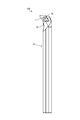
- FIG. 5 is a front view showing an example of a cutting tool according to the embodiment.
- FIG. 6 is a table showing the configuration of each sample.
- FIG. 7 is a table showing the results of the indentation hardness test for each sample.
- FIG. 8 is a graph showing the results of the indentation hardness test for cemented carbide with a metal layer and cemented carbide without a metal layer.
- FIG. 9 is a graph showing the results of the indentation hardness test for the cemented carbide with the metal layer and the cemented carbide without the metal layer, and is a graph showing the results of the indentation hardness test for the cermet with the metal layer and the cermet without the metal layer.
- FIG. 10 is a graph showing changes in the residual stress of the coating film when the film thickness of the metal layer is changed.
- the embodiment a mode for carrying out the covering tool and the cutting tool according to the present disclosure (hereinafter, referred to as “the embodiment”) will be described in detail with reference to the drawings. It should be noted that this embodiment does not limit the covering tool and the cutting tool according to the present disclosure. In addition, each embodiment can be appropriately combined as long as the processing contents do not contradict each other. Further, in each of the following embodiments, the same parts are designated by the same reference numerals, and duplicate description is omitted.
- the present disclosure is made in view of the above, and provides a coating tool and a cutting tool capable of improving the adhesion between the coating film and the substrate.
- FIG. 1 is a perspective view showing an example of a covering tool according to an embodiment.
- FIG. 2 is a side sectional view showing an example of the covering tool according to the embodiment.
- the covering tool 1 according to the embodiment has a tip body 2.
- Chip body 2 has, for example, a hexahedron shape in which the shapes of the upper surface and the lower surface (the surface intersecting the Z axis shown in FIG. 1) are parallelograms.
- the cutting edge portion has a first surface (for example, an upper surface) and a second surface (for example, a side surface) connected to the first surface.
- the first surface functions as a "scoop surface” for scooping chips generated by cutting
- the second surface functions as a "relief surface”.
- a cutting edge is located at least a part of the ridge line where the first surface and the second surface intersect, and the covering tool 1 cuts the work material by hitting the cutting edge against the work material.
- a through hole 5 that penetrates the chip body 2 up and down is located in the center of the chip body 2.
- a screw 75 for attaching the covering tool 1 to the holder 70, which will be described later, is inserted into the through hole 5 (see FIG. 5).
- the chip body 2 has a substrate 10 and a coating film 20.
- the substrate 10 is formed of, for example, a cemented carbide.
- the cemented carbide contains W (tungsten), specifically WC (tungsten carbide). Further, the cemented carbide may contain Ni (nickel) or Co (cobalt).
- the substrate 10 may be formed of cermet.
- the cermet contains, for example, Ti (titanium), specifically TiC (titanium carbide) or TiN (titanium nitride). Further, the cermet may contain Ni or Co.
- the coating film 20 will be described later.
- the coating film 20 is coated on the substrate 10 for the purpose of improving the abrasion resistance, heat resistance, etc. of the substrate 10.
- the coating film 20 covers the substrate 10 as a whole.
- the coating film 20 may be located at least on the substrate 10.
- the coating film 20 is located on the first surface (here, the upper surface) of the substrate 10, the wear resistance and heat resistance of the first surface are high.
- the coating film 20 is located on the second surface (here, the side surface) of the substrate 10, the wear resistance and heat resistance of the second surface are high.
- FIG. 3 is a cross-sectional view showing an example of the coating film 20 according to the embodiment.
- the coating film 20 has a hard layer 21.
- the hard layer 21 is a layer having excellent wear resistance as compared with the metal layer 22 described later.
- the hard layer 21 has one or more metal nitride layers.
- the hard layer 21 may be one layer. Further, as shown in FIG. 3, a plurality of metal nitride layers may be overlapped. Further, the hard layer 21 may have a laminated portion 23 in which a plurality of metal nitride layers are laminated, and a third metal nitride layer 24 located on the laminated portion 23. The configuration of the hard layer 21 will be described later.
- the coating film 20 has a metal layer 22.
- the metal layer 22 is located between the substrate 10 and the hard layer 21. Specifically, the metal layer 22 is in contact with the upper surface of the substrate 10 on one surface (here, the lower surface) and is in contact with the lower surface of the hard layer 21 on the other surface (here, the upper surface).
- the metal layer 22 has higher adhesion to the substrate 10 than the hard layer 21.
- metal elements having such properties include Zr, Hf, V, Nb, Ta, Cr, Mo, W, Al, Si, Y, and Ti.
- the metal layer 22 contains at least one of the above metal elements.
- the simple substance of Ti, the simple substance of Zr, the simple substance of V, the simple substance of Cr, and the simple substance of Al are not used as the metal layer 22. This is because all of these have a low melting point and low oxidation resistance, and thus are not suitable for use in cutting tools. Further, the simple substance of Hf, the simple substance of Nb, the simple substance of Ta, and the simple substance of Mo have low adhesion to the substrate 10. However, this does not apply to alloys containing Ti, Zr, V, Cr, Ta, Nb, Hf, and Al.
- the metal layer 22 may be an Al—Cr alloy layer containing an Al—Cr alloy. Since the metal layer 22 has particularly high adhesion to the substrate 10, the effect of improving the adhesion between the substrate 10 and the coating film 20 is high.
- the Al content in the metal layer 22 may be higher than the Cr content in the metal layer 22.
- the composition ratio (atomic%) of Al and Cr in the metal layer 22 may be 70:30. With such a composition ratio, the adhesion between the substrate 10 and the metal layer 22 is higher.
- the metal layer 22 may contain components other than the above metal elements (Zr, Hf, V, Nb, Ta, Cr, Mo, W, Al, Si, Y, Ti). However, from the viewpoint of adhesion to the substrate 10, the metal layer 22 may contain at least 95 atomic% or more of the above metal elements in total. More preferably, the metal layer 22 may contain the above metal elements in a total amount of 98 atomic% or more. For example, when the metal layer 22 is an Al—Cr alloy layer, the metal layer 22 may contain at least 95% or more of Al and Cr in total. Further, the metal layer 22 may contain at least 98% or more of Al and Cr in total. The proportion of the metal component in the metal layer 22 can be specified by, for example, analysis using an EDS (energy dispersive X-ray spectrometer).
- EDS energy dispersive X-ray spectrometer
- the substrate 10 may have a bonding phase such as Co.
- the bonded phase composed of metal has a high affinity with the metal layer 22. Therefore, by providing the bonding phase on the substrate 10, the adhesion between the substrate 10 and the metal layer 22 can be further enhanced.
- the metal layer 22 having a higher wettability with the base 10 than the hard layer 21 is provided between the base 10 and the hard layer 21 to cover the base 10 and the coating tool 1.
- the adhesion with the film 20 can be improved. Since the metal layer 22 has high adhesion to the hard layer 21, it is unlikely that the hard layer 21 will peel off from the metal layer 22.
- the covering tool 1 may have a compound containing a metal element contained in the base 10 and a metal element contained in the metal layer 22 at the interface F between the base 10 and the metal layer 22. ..
- the substrate 10 may be a cemented carbide
- the metal layer 22 may be a TiSi layer containing Ti and Si.
- the covering tool 1 may have TiW (titanium tungsten) at the interface F between the substrate 10 and the metal layer 22.
- the presence of the compound containing the metal element contained in the base 10 and the metal element contained in the metal layer 22 at the interface F between the base 10 and the metal layer 22 causes the base 10 and the metal to be present.
- the adhesion with the layer 22 can be enhanced. Therefore, according to the coating tool 1, the adhesion between the coating film 20 and the substrate (here, the substrate 10) can be improved.
- the metal layer 22 is formed by using the arc ion plating method (AIP method).
- the AIP method is a method of forming a metal nitride by evaporating a target metal using an arc discharge in a vacuum atmosphere and combining it with an N 2 gas.
- the bias voltage applied to the substrate 10 to be coated may be 400 V or more.
- the hard layer 21 described later may also be formed by the AIP method.
- FIG. 4 is a schematic enlarged view of the H portion shown in FIG.
- the hard layer 21 has a laminated portion 23 located on the metal layer 22 and a third metal nitride layer 24 located on the laminated portion 23.
- the laminated portion 23 has a plurality of first metal nitride layers 23a and a plurality of second metal nitride layers 23b.
- the laminated portion 23 has a structure in which the first metal nitride layer 23a and the second metal nitride layer 23b are alternately laminated.
- the thickness of the first metal nitride layer 23a and the thickness of the second metal nitride layer 23b may be 50 nm or less, respectively.
- the first metal nitride layer 23a is a layer in contact with the metal layer 22, and the second metal nitride layer 23b is formed on the first metal nitride layer 23a.
- the first metal nitride layer 23a and the second metal nitride layer 23b may contain the metal contained in the metal layer 22.
- the metal layer 22 contains two types of metals (here, "first metal” and "second metal”).
- the first metal nitride layer 23a contains the nitrides of the first metal and the third metal.
- the third metal is a metal that is not contained in the metal layer 22.
- the second metal nitride layer 23b contains a first metal and a second metal nitride.
- the metal layer 22 may contain Al and Cr.
- the first metal nitride layer 23a may contain Al.
- the first metal nitride layer 23a may be an AlTiN layer containing AlTiN, which is a nitride of Al and Ti.
- the second metal nitride layer 23b may be an AlCrN layer containing AlCrN, which is a nitride of Al and Cr.
- the adhesion between the metal layer 22 and the hard layer 21 is high. This makes it difficult for the hard layer 21 to peel off from the metal layer 22, so that the coating film 20 has high durability.
- the first metal nitride layer 23a that is, the AlTiN layer is excellent in, for example, wear resistance in addition to the adhesion to the metal layer 22 described above.
- the second metal nitride layer 23b that is, the AlCrN layer is excellent in heat resistance and oxidation resistance, for example.
- the coating film 20 contains the first metal nitride layer 23a and the second metal nitride layer 23b having different compositions to control the properties such as wear resistance and heat resistance of the hard layer 21. be able to. As a result, the tool life of the covering tool 1 can be extended.
- the hard layer 21 according to the embodiment it is possible to improve mechanical properties such as adhesion to the metal layer 22 and abrasion resistance while maintaining the excellent heat resistance of AlCrN.
- the third metal nitride layer 24 may be located on the laminated portion 23. Specifically, the third metal nitride layer 24 is in contact with the second metal nitride layer 23b of the laminated portion 23.
- the third metal nitride layer 24 is, for example, a metal nitride layer (AlTiN layer) containing Ti and Al, like the first metal nitride layer 23a.
- the thickness of the third metal nitride layer 24 may be thicker than the thickness of each of the first metal nitride layer 23a and the second metal nitride layer 23b. Specifically, when the thickness of the first metal nitride layer 23a and the second metal nitride layer 23b is 50 nm or less as described above, the thickness of the third metal nitride layer 24 may be 1 ⁇ m or more. For example, the thickness of the third metal nitride layer 24 may be 1.2 ⁇ m.
- the welding resistance of the covering tool 1 can be improved.
- the wear resistance of the covering tool 1 can be improved.
- the oxidation start temperature of the third metal nitride layer 24 is high, the oxidation resistance of the covering tool 1 can be improved.
- the thickness of the third metal nitride layer 24 may be thicker than the thickness of the laminated portion 23. Specifically, in the embodiment, when the thickness of the laminated portion 23 is 0.5 ⁇ m or less, the thickness of the third metal nitride layer 24 may be 1 ⁇ m or more. For example, when the thickness of the laminated portion 23 is 0.3 ⁇ m, the thickness of the third metal nitride layer 24 may be 1.2 ⁇ m.
- the thickness of the metal layer 22 may be, for example, 0.1 ⁇ m or more and less than 0.6 ⁇ m. That is, the metal layer 22 may be thicker than each of the first metal nitride layer 23a and the second metal nitride layer 23b, and may be thinner than the laminated portion 23.
- the first metal nitride layer 23a may be a nitride layer containing Al, Cr and Si (AlCrSiN layer), and the second metal nitride layer 23b is Ti. It may be a nitride layer (TiSiN layer) containing Si and Si.
- the composition ratio of Cr in the first metal nitride layer 23a is preferably higher than the composition ratio of Al in the first metal nitride layer 23a. That is, the first metal nitride layer 23a is preferably Cr-rich.
- the composition ratio (atomic%) of Al and Cr in the AlCrSiN layer is preferably 40:50. With such a composition ratio, the peeling resistance of the coating film 20 can be improved as compared with the case where Al-rich is used.
- FIG. 5 is a front view showing an example of a cutting tool according to the embodiment.
- the cutting tool 100 has a covering tool 1 and a holder 70 for fixing the covering tool 1.
- the holder 70 is a rod-shaped member extending from the first end (upper end in FIG. 5) to the second end (lower end in FIG. 5).
- the holder 70 is made of, for example, steel or cast iron. In particular, it is preferable to use steel having high toughness among these members.
- the holder 70 has a pocket 73 at the end on the first end side.
- the pocket 73 is a portion on which the covering tool 1 is mounted, and has a seating surface that intersects the rotation direction of the work material and a restraining side surface that is inclined with respect to the seating surface.
- the seating surface is provided with a screw hole for screwing a screw 75, which will be described later.
- the covering tool 1 is located in the pocket 73 of the holder 70 and is attached to the holder 70 by the screw 75. That is, the screw 75 is inserted into the through hole 5 of the covering tool 1, and the tip of the screw 75 is inserted into the screw hole formed on the seating surface of the pocket 73 to screw the screw portions together. As a result, the covering tool 1 is attached to the holder 70 so that the cutting edge portion protrudes outward from the holder 70.
- a cutting tool used for so-called turning is illustrated.
- the turning process include inner diameter processing, outer diameter processing, and grooving processing.
- the cutting tool is not limited to the one used for turning.
- the covering tool 1 may be used as the cutting tool used for the milling process.
- the cutting process of the work material includes (1) a process of rotating the work material, (2) a process of bringing the cutting edge of the covering tool 1 into contact with the rotating work material to cut the work material, and (3) Includes a step of separating the covering tool 1 from the work material.
- Typical examples of the material of the work material include carbon steel, alloy steel, stainless steel, cast iron, non-ferrous metal and the like.
- Example 1 Push-in hardness test
- the inventor of the present application conducted an indentation hardness test on each of a sample in which a coating film was formed on a cemented carbide and a sample in which a coating film was formed on a cermet.
- the samples are the following four types.
- FIG. 6 is a table showing the configuration of each sample.
- cemented carbide with a metal layer has a coating film composed of a metal layer and a hard layer on a substrate made of cemented carbide. Specifically, the metal layer is located on the substrate, and the hard layer is located on the metal layer.
- cemented carbide without a metal layer has a coating film made of a hard layer on a substrate made of cemented carbide.
- a cermet with a metal layer has a coating film composed of a metal layer and a hard layer on a substrate made of cermet
- a cermet without a metal layer has a coating made of a hard layer on a substrate made of cermet. It has a cermet membrane.
- the metal layer in cemented carbide with metal layer and cermet with metal layer contains Al and Cr.
- the specific composition of such a metal layer is Al 70 Cr 30 . That is, the metal layer contains 70 atomic% of Al and 30 atomic% of Cr.
- the thickness of the metal layer is 0.2 ⁇ m.
- the hard layer of each sample has a first metal nitride layer, a second metal nitride layer, and a third metal nitride layer.
- the first metal nitride layer and the second metal nitride layer are laminated alternately.
- the third metal nitride layer is located on the first metal nitride layer and the second metal nitride layer which are alternately laminated.
- the ratio of only the metal component of the first metal nitride layer described as TiAlNbWSiN in FIG. 6 is 42 atomic% for Ti, 48 atomic% for Al, 3 atomic% for Nb, 4 atomic% for W, and 3 atoms for Si. %. Further, the first metal nitride layer contains approximately 100 atomic% of N with respect to 100 atomic% of the metal component. The thickness of one first metal nitride layer is 50 nm.
- the ratio of only the metal component of the second metal nitride layer described as AlCrN in FIG. 6 is 70 atomic% for Al and 30 atomic% for Cr. Further, the second metal nitride layer contains approximately 100 atomic% of N with respect to 100 atomic% of the metal component. The thickness of one second metal nitride layer is 50 nm.
- the total thickness of the plurality of first metal nitride layers and the plurality of second metal nitride layers is 0.5 ⁇ m.
- the composition of the third metal nitride layer is the same as the composition of the first metal nitride layer.
- the thickness of the third metal nitride layer is 2 ⁇ m.
- FIGS. 7 to 9 The results of the indentation hardness test for such a sample are shown in FIGS. 7 to 9.
- FIG. 7 is a table showing the results of the indentation hardness test for each sample.
- FIG. 8 is a graph showing the results of the indentation hardness test for the superhard with the metal layer and the superhard without the metal layer
- FIG. 9 is the indentation hardness test for the superhard with the metal layer and the superhard without the metal layer. It is a graph which shows the result of the indentation hardness test for the cermet with a metal layer and the cermet without a metal layer.
- the thickness of the coating film was measured in the cross section of the substrate orthogonal to the surface of the substrate.
- the thickness of the coating film was 2.7 ⁇ m when it had a metal layer. When the metal layer was not provided, the thickness of the coating film was 2.5 ⁇ m.
- the indenter was pushed from the surface of the coating film by 20% of the thickness of the coating film.
- the indentation of the indenter onto the surface of the coating film was increased approximately every 0.02 ⁇ m. This pushing depth can be increased by increasing the pushing load. Increasing the indentation depth by 0.02 ⁇ m is, in other words, increasing the indentation load by approximately 5 mN.
- the hardness from the surface of the coating film to the vicinity of the surface of the substrate can be measured.
- the hardness of the coating film is, as described above, the hardness obtained by pushing the indenter from the surface of the coating film to a depth of 20% of the coating film while changing the pushing load of the indenter. Is. In the indentation hardness test, the deeper the indentation depth, the deeper the hardness of the region from the surface of the coating film can be measured.
- the measurement result of cemented carbide with a metal layer is shown by a white circle, and the measurement result of cemented carbide without a metal layer is shown by a black triangle.
- the measurement result of the cermet with a metal layer is shown by a white circle, and the measurement result of the cermet without a metal layer is shown by a black triangle.
- the cemented carbide with a metal layer has a higher hardness as a whole than the cemented carbide without a metal layer.
- This increase in hardness is remarkable in the region where the indentation depth is 100 nm or more and 200 nm or less.
- the hardness at a pressing depth of 100 nm or more and 200 nm or less indicates the hardness of the hard layer. From this, it can be seen that the cemented carbide with a metal layer has a higher hardness in the hard layer than the cemented carbide without a metal layer.
- This tendency is the same for cermets with a metal layer. That is, as shown in FIG. 9, it can be seen that the cermet with a metal layer also has a higher hardness in the hard layer than the cermet without a metal layer.
- FIG. 10 is a graph showing changes in the residual stress of the coating film when the film thickness of the metal layer is changed.
- FIG. 10 shows the result of measuring the residual stress of the coating film based on the amount of warping of the stainless steel plate on which the coating film with the metal layer is formed.
- the result of the film thickness of 0 ⁇ m shows the residual stress of the coating film without the metal layer, that is, the coating film with only the hard layer.
- the results of the film thicknesses of 0.2 ⁇ m, 0.4 ⁇ m, and 0.6 ⁇ m indicate the residual stress of the coating film with the metal layer.
- the coating film with the metal layer has a higher residual stress than the coating film without the metal layer.
- the higher the residual stress the higher the hardness of the coating film. Therefore, it can be seen that the hardness of the coating film is increased by forming the metal layer.
- the following can be considered as one of the reasons why the residual stress of the coating film is increased by the metal layer. That is, in PVD coating, a bias voltage is applied to an object to be filmed (cemented carbide, etc.), but by forming a metal layer, more ions are filmed when the bias voltage is applied. You will be attracted to the object. As a result, it is considered that a larger residual stress was generated in the coating film with the metal layer as compared with the coating film without the metal layer.
- the film thickness of the metal layer is preferably 0.1 ⁇ m or more and less than 0.6 ⁇ m.
- the cemented carbide with a metal layer and the cermet with a metal layer have a hardness valley in the vicinity of a pressing depth of 300 to 350 nm. This is a feature not found in metal-less carbide and metal-less cermets.
- the hardness in the vicinity of the indentation depth of 300 to 350 nm indicates the hardness of the metal layer, and since the metal layer is softer than the hard layer, it is considered that such a valley of hardness is formed.
- the "maximum hardness” is the maximum value of hardness in the measurement range (range from the surface of the coating layer to 20% of the depth of the coating layer), and the “minimum hardness” is It is the minimum value of hardness in the above measurement range.
- the “maximum hardness load” is the indenter pushing load at the maximum hardness
- the “maximum hardness depth” is the pushing depth of the indenter at the maximum hardness.
- the “minimum hardness load” is the indenter pushing load at the minimum hardness
- the “minimum hardness depth” is the pushing depth of the indenter at the minimum hardness.
- the “maximum hardness difference” is the difference between the maximum hardness and the minimum hardness.
- the “average hardness” is an average value of hardness in the measurement range.
- first hardness the minimum hardness
- second hardness the maximum hardness
- first hardness depth the indentation depth in the second hardness
- the second hardness depth is shallower than the first hardness depth in both the cemented carbide with a metal layer and the cermet with a metal layer. That is, it can be seen that both the cemented carbide with the metal layer and the cermet with the metal layer have the maximum hardness on the surface layer side of the coating film. Further, in both the cemented carbide with a metal layer and the cermet with a metal layer, the difference between the first hardness and the second hardness (maximum hardness difference) is larger than 7 GPa.
- the coating film may have a region having a high hardness and a region having a low hardness. Further, the region having high hardness may be located closer to the surface side of the coating film than the region having low altitude, and the difference may be larger than 7 GPa. In this case, the region with high hardness has high wear resistance, and the region with low hardness has high fracture resistance. Therefore, a coating tool having such a coating film has a long life.
- the first hardness depth is larger than 100 nm, which is the minimum value of the indentation depth.
- a region having a hardness lower than the first hardness is located on the surface side of the coating film. Therefore, a coating tool having such a coating film has relatively high toughness on the surface side, and initial defects are unlikely to occur.
- the minimum value (100 nm) of the indentation depth is defined as the "third hardness depth”
- the hardness at the third hardness depth is defined as the "third hardness”.
- the cemented carbide with a metal layer has a fourth hardness, which is lower than the third hardness, between the third load and the first load.
- a coating tool having a coating film in which low hardness regions and high hardness regions are alternately located has a long life.
- the first hardness depth of cemented carbide with a metal layer may be 300 nm or more and 600 nm or less.
- the region with high hardness is located near the surface of the coating layer, and the region with the best wear resistance is exposed at a relatively early stage. Therefore, a coating tool having such a coating film has a long life.
- Example 2 Scratch test and peeling test
- the inventor of the present application conducted a scratch test and a peeling test on each of the above-mentioned samples of cemented carbide without a metal layer, cemented carbide with a metal layer, cermet without a metal layer, and cermet with a metal layer.
- the scratch test is evaluated by the magnitude of the peeling load, and the larger the peeling load, the more difficult it is to peel off. Further, the longer the peeling time, the more difficult it is to peel.
- the scratch test was performed on a diamond indenter having a tip shape with an R (radius of curvature) of 200 ⁇ m under the conditions of a speed of 10 mm / min and a load speed of 100 N per minute.
- a tool-shaped sample of CNGA120408S01225 was used for the hardened material of the work material SCM415, and the cutting speed was 150 m / min, the feed rate was 0.1 mm / rotation, and the depth of cut was 0.2 mm. The time required for the hard layer to peel off was evaluated.
- the cemented carbide with the metal layer has a larger peeling load and a significantly longer peeling time than the cemented carbide without the metal layer. Further, when comparing the cermet without the metal layer and the cermet with the metal layer, the cermet with the metal layer had a larger peeling load and a significantly longer peeling time than the cermet without the metal layer. As described above, the cemented carbide with a metal layer and the cermet with a metal layer are less likely to cause peeling of the coating film as compared with the cemented carbide without a metal layer and the cermet without a metal layer, that is, the durability of the coating film is high.
- ⁇ Modification example> In the above-described embodiment, an example is shown in which the shapes of the upper surface and the lower surface of the covering tool 1 are parallelograms, but the shapes of the upper surface and the lower surface of the covering tool 1 may be rhombuses, squares, or the like. Further, the shape of the upper surface and the lower surface of the covering tool 1 may be a triangle, a pentagon, a hexagon, or the like.
- the shape of the covering tool 1 may be a positive type or a negative type.
- the positive type is a type in which the side surface is inclined with respect to the central axis passing through the center of the upper surface and the center of the lower surface of the covering tool 1
- the negative type is a type in which the side surface is parallel to the central axis.
- the covering tool 1 has been described as being used for cutting, but the covering tool according to the present application can be applied to other than cutting tools such as excavation tools and cutting tools.
- Base 20 Coating film 21
- Hard layer 22 Metal layer 23 Laminated part 23a 1st metal nitride layer 23b 2nd metal nitride layer 24 3rd metal nitride layer 70 Holder 73 Pocket 75 Screw 100 cutting tool
Landscapes
- Chemical & Material Sciences (AREA)
- Engineering & Computer Science (AREA)
- Mechanical Engineering (AREA)
- Chemical Kinetics & Catalysis (AREA)
- Materials Engineering (AREA)
- Metallurgy (AREA)
- Organic Chemistry (AREA)
- Inorganic Chemistry (AREA)
- Cutting Tools, Boring Holders, And Turrets (AREA)
- Physical Vapour Deposition (AREA)
Abstract
本開示による被覆工具(1)は、基体(10)と、被覆膜(20)とを有する。基体(10)は、超硬合金またはサーメットからなる。被覆膜(20)は、基体(10)の上に位置する。また、被覆膜(20)の表面から、圧子の押し込み荷重を変化させながら被覆膜(20)の20%の深さまで圧子を押し込んで硬度を測定した場合において、硬度のうち最小硬度を第1硬度、最大硬度を第2硬度とし、第1硬度における深さを第1硬度深さ、第2硬度における深さを第2硬度深さとしたとき、第2硬度深さは、第1硬度深さよりも浅く、第1硬度と第2硬度との差は、7GPaよりも大きい。
Description
本開示は、被覆工具および切削工具に関する。
旋削加工や転削加工等の切削加工に用いられる工具として、超硬合金、サーメット、セラミックス等の基体の表面を被覆膜でコーティングすることによって耐摩耗性等を向上させた被覆工具が知られている(特許文献1参照)。
本開示の一態様による被覆工具は、基体と、被覆膜とを有する。基体は、超硬合金またはサーメットからなる。被覆膜は、基体の上に位置する。また、被覆膜の表面から、圧子の押し込み荷重を変化させながら被覆膜の20%の深さまで圧子を押し込んで硬度を測定した場合において、硬度のうち最小硬度を第1硬度、最大硬度を第2硬度とし、第1硬度における深さを第1硬度深さ、第2硬度における深さを第2硬度深さとしたとき、第2硬度深さは、第1硬度深さよりも浅く、第1硬度と第2硬度との差は、7GPaよりも大きい。
以下に、本開示による被覆工具および切削工具を実施するための形態(以下、「実施形態」と記載する)について図面を参照しつつ詳細に説明する。なお、この実施形態により本開示による被覆工具および切削工具が限定されるものではない。また、各実施形態は、処理内容を矛盾させない範囲で適宜組み合わせることが可能である。また、以下の各実施形態において同一の部位には同一の符号を付し、重複する説明は省略される。
また、以下に示す実施形態では、「一定」、「直交」、「垂直」あるいは「平行」といった表現が用いられる場合があるが、これらの表現は、厳密に「一定」、「直交」、「垂直」あるいは「平行」であることを要しない。すなわち、上記した各表現は、例えば製造精度、設置精度などのずれを許容するものとする。
上述した従来技術には、被覆膜と基体との密着性を向上させるという点で更なる改善の余地がある。
本開示は、上記に鑑みてなされたものであって、被覆膜と基体との密着性を向上させることができる被覆工具および切削工具を提供する。
<被覆工具>
図1は、実施形態に係る被覆工具の一例を示す斜視図である。また、図2は、実施形態に係る被覆工具の一例を示す側断面図である。図1に示すように、実施形態に係る被覆工具1は、チップ本体2を有する。
図1は、実施形態に係る被覆工具の一例を示す斜視図である。また、図2は、実施形態に係る被覆工具の一例を示す側断面図である。図1に示すように、実施形態に係る被覆工具1は、チップ本体2を有する。
(チップ本体2)
チップ本体2は、たとえば、上面および下面(図1に示すZ軸と交わる面)の形状が平行四辺形である六面体形状を有する。
チップ本体2は、たとえば、上面および下面(図1に示すZ軸と交わる面)の形状が平行四辺形である六面体形状を有する。
チップ本体2の1つのコーナー部は、切刃部として機能する。切刃部は、第1面(たとえば上面)と、第1面に連接する第2面(たとえば側面)とを有する。実施形態において、第1面は切削により生じた切屑をすくい取る「すくい面」として機能し、第2面は「逃げ面」として機能する。第1面と第2面とが交わる稜線の少なくとも一部には、切刃が位置しており、被覆工具1は、かかる切刃を被削材に当てることによって被削材を切削する。
チップ本体2の中央部には、チップ本体2を上下に貫通する貫通孔5が位置する。貫通孔5には、後述するホルダ70に被覆工具1を取り付けるためのネジ75が挿入される(図5参照)。
図2に示すように、チップ本体2は、基体10と、被覆膜20とを有する。
(基体10)
基体10は、基体10は、たとえば超硬合金で形成される。超硬合金は、W(タングステン)、具体的には、WC(炭化タングステン)を含有する。また、超硬合金は、Ni(ニッケル)やCo(コバルト)を含有していてもよい。また、基体10は、サーメットで形成されてもよい。サーメットは、たとえばTi(チタン)、具体的には、TiC(炭化チタン)またはTiN(窒化チタン)を含有する。また、サーメットは、NiやCoを含有していてもよい。被覆膜20については後述する。
基体10は、基体10は、たとえば超硬合金で形成される。超硬合金は、W(タングステン)、具体的には、WC(炭化タングステン)を含有する。また、超硬合金は、Ni(ニッケル)やCo(コバルト)を含有していてもよい。また、基体10は、サーメットで形成されてもよい。サーメットは、たとえばTi(チタン)、具体的には、TiC(炭化チタン)またはTiN(窒化チタン)を含有する。また、サーメットは、NiやCoを含有していてもよい。被覆膜20については後述する。
(被覆膜20)
被覆膜20は、例えば、基体10の耐摩耗性、耐熱性等を向上させることを目的として基体10に被覆される。図2の例では、被覆膜20が基体10を全体的に被覆している。被覆膜20は、少なくとも基体10の上に位置していればよい。被覆膜20が基体10の第1面(ここでは、上面)に位置する場合、第1面の耐摩耗性、耐熱性が高い。被覆膜20が基体10の第2面(ここでは、側面)に位置する場合、第2面の耐摩耗性、耐熱性が高い。
被覆膜20は、例えば、基体10の耐摩耗性、耐熱性等を向上させることを目的として基体10に被覆される。図2の例では、被覆膜20が基体10を全体的に被覆している。被覆膜20は、少なくとも基体10の上に位置していればよい。被覆膜20が基体10の第1面(ここでは、上面)に位置する場合、第1面の耐摩耗性、耐熱性が高い。被覆膜20が基体10の第2面(ここでは、側面)に位置する場合、第2面の耐摩耗性、耐熱性が高い。
ここで、被覆膜20の具体的な構成について図3を参照して説明する。図3は、実施形態に係る被覆膜20の一例を示す断面図である。
図3に示すように、被覆膜20は、硬質層21を有する。硬質層21は、後述する金属層22と比較して耐摩耗性に優れた層である。硬質層21は、1層以上の金属窒化物層を有する。硬質層21は1層であってもよい。また、図3に示すように複数の金属窒化物層が重なっていてもよい。また、硬質層21は、複数の金属窒化物層が積層された積層部23と、積層部23の上に位置する第3金属窒化物層24とを有していてもよい。かかる硬質層21の構成については後述する。
(金属層22)
また、被覆膜20は、金属層22を有する。金属層22は、基体10と硬質層21との間に位置する。具体的には、金属層22は、一方の面(ここでは下面)において基体10の上面に接し、且つ、他方の面(ここでは上面)において硬質層21の下面に接する。
また、被覆膜20は、金属層22を有する。金属層22は、基体10と硬質層21との間に位置する。具体的には、金属層22は、一方の面(ここでは下面)において基体10の上面に接し、且つ、他方の面(ここでは上面)において硬質層21の下面に接する。
金属層22は、基体10との密着性が硬質層21と比べて高い。このような特性を有する金属元素としては、たとえば、Zr、Hf、V、Nb、Ta、Cr、Mo、W、Al、Si、Y、Tiが挙げられる。金属層22は、上記金属元素のうち少なくとも1種以上の金属元素を含有する。
なお、Tiの単体、Zrの単体、Vの単体、Crの単体およびAlの単体は、金属層22としては用いられない。これらはいずれも融点が低く、耐酸化性が低いことから、切削工具への使用に適さないためである。また、Hfの単体、Nbの単体、Taの単体、Moの単体は基体10との密着性が低い。ただし、Ti、Zr、V、Cr、Ta、Nb、Hf、Alを含む合金については、この限りではない。
金属層22は、Al-Cr合金を含有するAl-Cr合金層であってもよい。かかる金属層22は、基体10との密着性が特に高いことから、基体10と被覆膜20との密着性を向上させる効果が高い。
金属層22がAl-Cr合金層である場合、金属層22におけるAlの含有量は、金属層22におけるCrの含有量よりも多くてもよい。たとえば、金属層22におけるAlとCrとの組成比(原子%)は、70:30であってもよい。このような組成比率とすることで、基体10と金属層22との密着性はより高い。
金属層22は、上記金属元素(Zr、Hf、V、Nb、Ta、Cr、Mo、W、Al、Si、Y、Ti)以外の成分を含有していてもよい。ただし、基体10との密着性の観点から、金属層22は、上記金属元素を合量で少なくとも95原子%以上含有していてもよい。より好ましくは、金属層22は、上記金属元素を合量で98原子%以上含有してもよい。たとえば、金属層22がAl-Cr合金層である場合、金属層22は、少なくとも、AlおよびCrを合量で95%以上含有していてもよい。さらに金属層22は、少なくとも、AlおよびCrを合量で98%以上含有していてもよい。なお、金属層22における金属成分の割合は、たとえば、EDS(エネルギー分散型X線分光器)を用いた分析により特定可能である。
基体10は、Co等の結合相を有していてもよい。金属で構成される結合相は、金属層22との親和性が高い。このため、基体10に結合相を設けることで、基体10と金属層22との密着性をより高めることができる。
このように、実施形態に係る被覆工具1では、基体10との濡れ性が硬質層21と比べて高い金属層22を基体10と硬質層21との間に設けることにより、基体10と被覆膜20との密着性を向上させることができる。なお、金属層22は、硬質層21との密着性も高いため、硬質層21が金属層22から剥離するといったことも生じにくい。
また、被覆工具1は、基体10と金属層22との界面Fに、基体10に含有される金属元素と、金属層22に含有される金属元素とを含有する化合物を有していてもよい。
たとえば、基体10は、超硬合金であり、金属層22は、TiおよびSiを含有するTiSi層であってもよい。この場合、被覆工具1は、基体10と金属層22との界面Fに、TiW(チタンタングステン)を有していてもよい。
このように、基体10と金属層22との界面Fに、基体10に含有される金属元素と、金属層22に含有される金属元素とを含有する化合物が存在することで、基体10と金属層22との密着力を高めることができる。したがって、被覆工具1によれば、被覆膜20と基体(ここでは、基体10)との密着性を向上させることができる。
金属層22は、アークイオンプレーティング法(AIP法)を用いて成膜される。AIP法は、真空雰囲気でアーク放電を利用してターゲット金属を蒸発させ、N2ガスと結合することによって金属窒化物を成膜する方法である。このとき、被コーティング物である基体10に印加されるバイアス電圧は、400V以上であってもよい。後述する硬質層21も、AIP法により成膜されてもよい。
(硬質層21)
次に、硬質層21の構成について図4を参照して説明する。図4は、図3に示すH部の模式拡大図である。
次に、硬質層21の構成について図4を参照して説明する。図4は、図3に示すH部の模式拡大図である。
図4に示すように、硬質層21は、金属層22の上に位置する積層部23と、積層部23の上に位置する第3金属窒化物層24とを有する。
積層部23は、複数の第1金属窒化物層23aと複数の第2金属窒化物層23bとを有する。積層部23は、第1金属窒化物層23aと第2金属窒化物層23bとが交互に積層された構成を有している。
第1金属窒化物層23aおよび第2金属窒化物層23bの厚みは、それぞれ50nm以下としてもよい。このように、第1金属窒化物層23aおよび第2金属窒化物層23bを薄く形成することで、第1金属窒化物層23aおよび第2金属窒化物層23bの残留応力が小さい。これにより、たとえば、第1金属窒化物層23aおよび第2金属窒化物層23bの剥離やクラック等が生じ難くなることから、被覆膜20の耐久性が高い。
第1金属窒化物層23aは、金属層22に接する層であり、第2金属窒化物層23bは、第1金属窒化物層23a上に形成される。
第1金属窒化物層23aおよび第2金属窒化物層23bは、金属層22に含まれる金属を含有していてもよい。
たとえば、金属層22に2種類の金属(ここでは、「第1の金属」、「第2の金属」とする)が含まれているとする。この場合、第1金属窒化物層23aは、第1の金属および第3の金属の窒化物を含有する。第3の金属は、金属層22に含まれない金属である。また、第2金属窒化物層23bは、第1の金属および第2の金属の窒化物を含有する。
たとえば、実施形態において、金属層22は、AlおよびCrを含有してもよい。この場合、第1金属窒化物層23aは、Alを含有してもよい。具体的には、第1金属窒化物層23aは、AlおよびTiの窒化物であるAlTiNを含有するAlTiN層であってもよい。また、第2金属窒化物層23bは、AlおよびCrの窒化物であるAlCrNを含有するAlCrN層であってもよい。
このように、金属層22に含まれる金属を含有する第1金属窒化物層23aを金属層22の上に位置させることで、金属層22と硬質層21との密着性が高い。これにより、硬質層21が金属層22から剥離し難くなるため、被覆膜20の耐久性が高い。
第1金属窒化物層23aすなわちAlTiN層は、上述した金属層22との密着性の他、たとえば耐摩耗性に優れる。また、第2金属窒化物層23bすなわちAlCrN層は、たとえば耐熱性、耐酸化性に優れる。このように、被覆膜20は、互いに異なる組成の第1金属窒化物層23aおよび第2金属窒化物層23bを含むことで、硬質層21の耐摩耗性や耐熱性等の特性を制御することができる。これにより、被覆工具1の工具寿命を延ばすことができる。たとえば、実施形態に係る硬質層21においては、AlCrNが持つ優れた耐熱性を維持しつつ、金属層22との密着性や耐摩耗性といった機械的性質を向上させることができる。
第3金属窒化物層24は、積層部23の上に位置してもよい。具体的には、第3金属窒化物層24は、積層部23のうち第2金属窒化物層23bと接する。第3金属窒化物層24は、たとえば、第1金属窒化物層23aと同様、TiおよびAlを含有する金属窒化物層(AlTiN層)である。
第3金属窒化物層24の厚みは、第1金属窒化物層23aおよび第2金属窒化物層23bの各厚みよりも厚くてもよい。具体的には、上述したように第1金属窒化物層23aおよび第2金属窒化物層23bの厚みは50nm以下とした場合、第3金属窒化物層24の厚みは、1μm以上としてもよい。たとえば、第3金属窒化物層24の厚みは、1.2μmであってもよい。
これにより、たとえば、第3金属窒化物層24の摩擦係数が低い場合には、被覆工具1の耐溶着性を向上させることができる。また、たとえば、第3金属窒化物層24の硬度が高い場合には、被覆工具1の耐摩耗性を向上させることができる。また、たとえば、第3金属窒化物層24の酸化開始温度が高い場合には、被覆工具1の耐酸化性を向上させることができる。
また、第3金属窒化物層24の厚みは、積層部23の厚みよりも厚くてもよい。具体的には、実施形態において、積層部23の厚みは0.5μm以下とした場合、第3金属窒化物層24の厚みは、1μm以上であってもよい。たとえば、積層部23の厚みが0.3μmである場合、第3金属窒化物層24の厚みは1.2μmであってもよい。このように、第3金属窒化物層24を積層部23よりも厚くすることで、上述した耐溶着性、耐摩耗性等を向上させる効果がさらに高い。
なお、金属層22の厚みは、たとえば0.1μm以上、0.6μm未満であってもよい。すなわち、金属層22は、第1金属窒化物層23aおよび第2金属窒化物層23bの各々よりも厚く、且つ、積層部23よりも薄くてもよい。
金属層22がTiSi層である場合、第1金属窒化物層23aは、Al,CrおよびSiを含有する窒化物層(AlCrSiN層)であってもよく、第2金属窒化物層23bは、TiおよびSiを含有する窒化物層(TiSiN層)であってもよい。
第1金属窒化物層23aがAlCrSiN層である場合、第1金属窒化物層23aにおけるCrの組成比率は、第1金属窒化物層23aにおけるAlの組成比率よりも多いことが好ましい。すなわち、第1金属窒化物層23aは、Crリッチであることが好ましい。たとえば、AlCrSiN層におけるAlとCrとの組成比(原子%)は、40:50であることが好ましい。このような組成比率とすることで、Alリッチとした場合と比較して、被覆膜20の耐剥離性を向上させることができる。
<切削工具>
次に、上述した被覆工具1を備えた切削工具の構成について図5を参照して説明する。図5は、実施形態に係る切削工具の一例を示す正面図である。
次に、上述した被覆工具1を備えた切削工具の構成について図5を参照して説明する。図5は、実施形態に係る切削工具の一例を示す正面図である。
図5に示すように、実施形態に係る切削工具100は、被覆工具1と、被覆工具1を固定するためのホルダ70とを有する。
ホルダ70は、第1端(図5における上端)から第2端(図5における下端)に向かって伸びる棒状の部材である。ホルダ70は、たとえば、鋼、鋳鉄製である。特に、これらの部材の中で靱性の高い鋼が用いられることが好ましい。
ホルダ70は、第1端側の端部にポケット73を有する。ポケット73は、被覆工具1が装着される部分であり、被削材の回転方向と交わる着座面と、着座面に対して傾斜する拘束側面とを有する。着座面には、後述するネジ75を螺合させるネジ孔が設けられている。
被覆工具1は、ホルダ70のポケット73に位置し、ネジ75によってホルダ70に装着される。すなわち、被覆工具1の貫通孔5にネジ75を挿入し、このネジ75の先端をポケット73の着座面に形成されたネジ孔に挿入してネジ部同士を螺合させる。これにより、被覆工具1は、切刃部分がホルダ70から外方に突出するようにホルダ70に装着される。
実施形態においては、いわゆる旋削加工に用いられる切削工具を例示している。旋削加工としては、例えば、内径加工、外径加工及び溝入れ加工が挙げられる。なお、切削工具としては旋削加工に用いられるものに限定されない。例えば、転削加工に用いられる切削工具に被覆工具1を用いてもよい。
たとえば、被削材の切削加工は、(1)被削材を回転させる工程、(2)回転する被削材に被覆工具1の切刃を接触させて被削材を切削する工程、および、(3)被覆工具1を被削材から離す工程を含む。なお、被削材の材質の代表例としては、炭素鋼、合金鋼、ステンレス、鋳鉄、または非鉄金属などが挙げられる。
(実施例1:押し込み硬さ試験)
本願発明者は、超硬合金上に被覆膜を形成したサンプルと、サーメット上に被覆膜を形成したサンプルのそれぞれについて、押し込み硬さ試験を行った。
本願発明者は、超硬合金上に被覆膜を形成したサンプルと、サーメット上に被覆膜を形成したサンプルのそれぞれについて、押し込み硬さ試験を行った。
サンプルは、以下の4種類である。
(1a)金属層を有する被覆膜を超硬合金上に形成したもの(以下、「金属層あり超硬」と記載する)
(1b)金属層を有しない被覆膜を超硬合金上に形成したもの(以下、「金属層なし超硬」と記載する)
(2a)金属層を有する被覆膜をサーメット上に形成したもの(以下、「金属層ありサーメット」と記載する)
(2b)金属層を有しない被覆膜をサーメット上に形成したもの(以下、「金属層なしサーメット」と記載する)
(1a)金属層を有する被覆膜を超硬合金上に形成したもの(以下、「金属層あり超硬」と記載する)
(1b)金属層を有しない被覆膜を超硬合金上に形成したもの(以下、「金属層なし超硬」と記載する)
(2a)金属層を有する被覆膜をサーメット上に形成したもの(以下、「金属層ありサーメット」と記載する)
(2b)金属層を有しない被覆膜をサーメット上に形成したもの(以下、「金属層なしサーメット」と記載する)
各サンプルの具体的な構成について図6を参照して説明する。図6は、各サンプルの構成を示す表である。
図6に示すように、金属層あり超硬は、超硬合金からなる基体の上に、金属層および硬質層からなる被覆膜を有する。具体的には、基体の上に金属層が位置し、金属層の上に硬質層が位置する。一方、金属層なし超硬は、超硬からなる基体の上に、硬質層からなる被覆膜を有する。同様に、金属層ありサーメットは、サーメットからなる基体の上に、金属層および硬質層からなる被覆膜を有し、金属層なしサーメットは、サーメットからなる基体の上に、硬質層からなる被覆膜を有する。
金属層あり超硬および金属層ありサーメットにおける金属層は、AlおよびCrを含有する。かかる金属層の具体的な組成は、Al70Cr30である。すなわち、金属層は、Alを70原子%、Crを30原子%含有する。また、金属層の厚みは、0.2μmである。
各サンプルの硬質層は、第1金属窒化物層、第2金属窒化物層および第3金属窒化物層を有する。第1金属窒化物層および第2金属窒化物層は、交互に積層される。また、第3金属窒化物層は、交互に積層された第1金属窒化物層および第2金属窒化物層の上に位置する。
図6においてTiAlNbWSiNと記載された第1金属窒化物層の金属成分のみの比率は、Tiが42原子%、Alが48原子%、Nbが3原子%、Wが4原子%、Siが3原子%である。また、第1金属窒化物層は、金属成分の100原子%に対しておよそ100原子%のNを含有している。1つの第1金属窒化物層の厚みは、50nmである。
図6においてAlCrNと記載された第2金属窒化物層の金属成分のみの比率は、Alが70原子%、Crが30原子%である。また、第2金属窒化物層は、金属成分の100原子%に対しておよそ100原子%のNを含有している。1つの第2金属窒化物層の厚みは、50nmである。
複数の第1金属窒化物層および複数の第2金属窒化物層の合計の厚みは、0.5μmである。
第3金属窒化物層の組成は、第1金属窒化物層の組成と同じである。第3金属窒化物層の厚みは、2μmである。
かかるサンプルに対する押し込み硬さ試験の結果を図7~図9に示す。図7は、各サンプルに対する押し込み硬さ試験の結果を示す表である。また、図8は、金属層あり超硬および金属層なし超硬に対する押し込み硬さ試験の結果を示すグラフであり、図9は、金属層あり超硬および金属層なし超硬に対する押し込み硬さ試験の結果を示すグラフで金属層ありサーメットおよび金属層なしサーメットに対する押し込み硬さ試験の結果を示すグラフである。
なお、本試験は、微小押し込み硬さ試験機「ENT-1100b/a」((株)エリオニクス製)を用いて行われた。
硬度の測定に先立ち、基体の表面に直交する基体の断面において被覆膜の厚みを測定した。被覆膜の厚みは、金属層を有する場合2.7μmであった。金属層を有しない場合被覆膜の厚みは2.5μmであった。圧子を被覆膜の表面から、被覆膜の厚みの20%分だけ押し込んだ。被覆膜の表面への圧子の押し込みは、およそ0.02μm毎に増加させた。この押し込み深さは押し込み荷重を増加させることで深くすることができる。押し込み深さを0.02μmずつ増加させるとは、言い換えると押し込み荷重をおおよそ5mNずつ増加させたことと同じである。
本試験では、被覆膜の厚みの20%の深さまで圧子を押し込むとほぼ被覆膜の表面から基体の表面付近の硬度が測定することができる。本開示において、被覆膜の硬度とは、上述したように、被覆膜の表面から、圧子の押し込み荷重を変化させながら被覆膜の20%の深さまで圧子を押し込んで得られる硬度のことである。押し込み硬さ試験では、押し込み深さが深いほど、被覆膜の表面からより深い領域の硬度を測定することが可能である。
図8には、金属層あり超硬の測定結果を白抜きの丸で、金属層なし超硬の測定結果を黒塗りの三角で示している。また、図9には、金属層ありサーメットの測定結果を白抜きの丸で、金属層なしサーメットの測定結果を黒塗りの三角で示している。
図8に示すように、金属層あり超硬は、金属層なし超硬と比較して全体的に硬度が高くなっていることがわかる。この硬度の上昇は、押し込み深さ100nm以上200nm以下の領域において顕著である。押し込み深さ100nm以上200nm以下における硬度は、硬質層の硬度を示している。このことから、金属層あり超硬は、金属層なし超硬と比較して、硬質層における硬度が高くなっていることがわかる。
この傾向は、金属層ありサーメットについても同様である。すなわち、図9に示すように、金属層ありサーメットも金属層なしサーメットと比較して硬質層における硬度が高くなっていることがわかる。
この点について図10を参照して説明する。図10は、金属層の膜厚を変化させた場合における被覆膜の残留応力の変化を示すグラフである。
図10には、金属層ありの被覆膜が成膜されたステンレス板の反り量に基づいて被覆膜の残留応力を測定した結果を示している。図10において、膜厚0μmの結果は、金属層なしの被覆膜すなわち硬質層のみの被覆膜の残留応力を示している。また、膜厚0.2μm、0.4μm、0.6μmの結果は、金属層ありの被覆膜の残留応力を示している。
図10に示すように、金属層ありの被覆膜は、金属層なしの被覆膜と比べて残留応力が高くなることがわかる。残留応力が高くなるほど、被覆膜の硬度は高くなる。したがって、金属層を形成することにより、被覆膜の硬度が高まることがわかる。
金属層によって被覆膜の残留応力が高まる理由の一つとしては、たとえば以下のことが考えられる。すなわち、PVDコーティングでは、被成膜対象物(超硬合金など)に対してバイアス電圧が印加されが、金属層を成膜することで、バイアス電圧を印加した際により多くのイオンが被成膜対象物に引きつけられるようになる。この結果、金属層なしの被覆膜と比較してより大きな残留応力が金属層ありの被覆膜に生じたと考えられる。
なお、金属層の膜厚を0.6μmとした場合、被覆膜の剥離が生じて残留応力が低下した。この結果から、金属層の膜厚は、0.1μm以上0.6μm未満であることが好ましい。
また、図8および図9に示すように、金属層あり超硬および金属層ありサーメットは、押し込み深さ300~350nm付近に硬度の谷を有する。これは、金属層なし超硬および金属層なしサーメットには見られない特徴である。押し込み深さ300~350nm付近の硬度は、金属層の硬度を示しており、金属層は硬質層と比較して柔らかいことから、このような硬度の谷ができたものと考えられる。
図7に示す結果のうち、「最大硬度」とは、測定範囲(被覆層の表面から被覆層の深さの20%までの範囲)における硬度の最大値であり、「最小硬度」とは、上記測定範囲における硬度の最小値である。「最大硬度荷重」とは、最大硬度における圧子の押し込み荷重であり、「最大硬度深さ」とは、最大硬度における圧子の押し込み深さである。「最小硬度荷重」とは、最小硬度における圧子の押し込み荷重であり、「最小硬度深さ」とは、最小硬度における圧子の押し込み深さである。
「最大硬度差」とは、最大硬度と最小硬度との差である。「平均硬度」とは、測定範囲における硬度の平均値である。
ここで、金属層あり超硬および金属層ありサーメットのそれぞれについて、最小硬度を「第1硬度」、最大硬度を「第2硬度」と記載する。また、第1硬度における押し込み深さを「第1硬度深さ」、第2硬度における押し込み深さを「第2硬度深さ」と記載する。
図8および図9に示すように、金属層あり超硬および金属層ありサーメットのいずれにおいても、第2硬度深さは、第1硬度深さよりも浅い。すなわち、金属層あり超硬および金属層ありサーメットのいずれも、被覆膜の表層側に最大硬度を有することがわかる。また、金属層あり超硬および金属層ありサーメットのいずれにおいても、第1硬度と第2硬度との差(最大硬度差)は、7GPaよりも大きい。
このように、被覆膜は、硬度の高い領域と硬度の低い領域とを有していてもよい。また、硬度の高い領域が高度の低い領域よりも被覆膜の表面側に位置し、その差が7GPaよりも大きくてもよい。この場合、硬度の高い領域が高い耐摩耗性を有し、硬度の低い領域が高い耐欠損性を有する。したがって、このような被覆膜を有する被覆工具は、長寿命を有する。
また、金属層あり超硬および金属層ありサーメットにおいて、第1硬度深さは、押し込み深さの最小値である100nmよりも大きい。
この場合、第1硬度よりも低い硬度を有する領域が被覆膜の表面側に位置する。したがって、このような被覆膜を有する被覆工具は、表面側において比較的靭性が高く、初期欠損が発生しにくい。
また、金属層あり超硬および金属層ありサーメットについて、押し込み深さの最小値(100nm)を「第3硬度深さ」とし、第3硬度深さにおける硬度を「第3硬度」とする。この場合、金属層あり超硬は、第3荷重と第1荷重との間に、第3硬度よりも硬度が低い第4硬度を有する。
このように、硬度の低い領域と硬度の高い領域とが交互に位置する被覆膜を有する被覆工具は、長寿命を有する。
金属層あり超硬における第1硬度深さは、300nm以上600nm以下であってもよい。
この場合、硬度の高い領域が被覆層の表面近傍に位置することになり、比較的早い時点で最も耐摩耗性に優れた領域が露出することになる。したがって、このような被覆膜を有する被覆工具は、長寿命を有する。
(実施例2:スクラッチ試験および剥離試験)
また、本願発明者は、上述した金属層なし超硬、金属層あり超硬、金属層なしサーメットおよび金属層ありサーメットの各サンプルについて、スクラッチ試験および剥離試験を行った。スクラッチ試験は剥離荷重の大きさで評価しており、剥離荷重が大きいほど、剥離しにくい。また、剥離時間は長いほど剥離しにくい。
また、本願発明者は、上述した金属層なし超硬、金属層あり超硬、金属層なしサーメットおよび金属層ありサーメットの各サンプルについて、スクラッチ試験および剥離試験を行った。スクラッチ試験は剥離荷重の大きさで評価しており、剥離荷重が大きいほど、剥離しにくい。また、剥離時間は長いほど剥離しにくい。
スクラッチ試験は、R(曲率半径)が200μmの先端形状のダイヤモンド圧子を10mm/分の速度および1分間に100Nの荷重速度の条件で行った。
剥離試験は、被加工材SCM415の焼き入れ材に対して、CNGA120408S01225の工具形状の試料を用いて、切削速度:150m/分、送り速度:0.1mm/回転、切込み:0.2mmの加工条件で行い、硬質層が剥離するまでの時間を評価した。
金属層なし超硬と金属層あり超硬とを比較すると、金属層あり超硬は、金属層なし超硬と比較して、剥離荷重は大きくなり、剥離時間も大幅に長くなった。また、金属層なしサーメットと金属層ありサーメットとを比較すると、金属層ありサーメットは、金属層なしサーメットと比較して、剥離荷重は大きくなり、剥離時間も大幅に長くなった。このように、金属層あり超硬および金属層ありサーメットは、金属層なし超硬および金属層なしサーメットと比較して被覆膜の剥離が生じ難い、すなわち、被覆膜の耐久性が高い。
<変形例>
上述した実施形態では、被覆工具1の上面および下面の形状が平行四辺形である場合の例を示したが、被覆工具1の上面および下面の形状は、ひし形や正方形等であってもよい。また、被覆工具1の上面および下面の形状は、三角形、五角形、六角形等であってもよい。
上述した実施形態では、被覆工具1の上面および下面の形状が平行四辺形である場合の例を示したが、被覆工具1の上面および下面の形状は、ひし形や正方形等であってもよい。また、被覆工具1の上面および下面の形状は、三角形、五角形、六角形等であってもよい。
また、被覆工具1の形状は、ポジティブ型であってもよいしネガティブ型であってもよい。ポジティブ型は、被覆工具1の上面の中心および下面の中心を通る中心軸に対して側面が傾斜しているタイプであり、ネガティブ型は、上記中心軸に対して側面が平行なタイプである。
上述した実施形態では、被覆工具1が切削加工に用いられるものとして説明したが、本願による被覆工具は、たとえば掘削用の工具や刃物など、切削工具以外への適用も可能である。
さらなる効果や変形例は、当業者によって容易に導き出すことができる。このため、本発明のより広範な態様は、以上のように表しかつ記述した特定の詳細および代表的な実施形態に限定されるものではない。したがって、添付の請求の範囲およびその均等物によって定義される総括的な発明の概念の精神または範囲から逸脱することなく、様々な変更が可能である。
1 被覆工具
2 チップ本体
5 貫通孔
10 基体
20 被覆膜
21 硬質層
22 金属層
23 積層部
23a 第1金属窒化物層
23b 第2金属窒化物層
24 第3金属窒化物層
70 ホルダ
73 ポケット
75 ネジ
100 切削工具
2 チップ本体
5 貫通孔
10 基体
20 被覆膜
21 硬質層
22 金属層
23 積層部
23a 第1金属窒化物層
23b 第2金属窒化物層
24 第3金属窒化物層
70 ホルダ
73 ポケット
75 ネジ
100 切削工具
Claims (18)
- 超硬合金またはサーメットからなる基体と、
前記基体の上に位置する被覆膜と
を有し、
前記被覆膜の表面から、圧子の押し込み荷重を変化させながら前記被覆膜の20%の深さまで前記圧子を押し込んで硬度を測定した場合において、
前記硬度のうち最小硬度を第1硬度、最大硬度を第2硬度とし、前記第1硬度における深さを第1硬度深さ、前記第2硬度における深さを第2硬度深さとしたとき、
前記第2硬度深さは、前記第1硬度深さよりも浅く、
前記第1硬度と前記第2硬度との差は、7GPaよりも大きい、被覆工具。 - 前記第1硬度深さは、100nmよりも大きい、請求項1に記載の被覆工具。
- 前記深さが100nmであるときの前記硬度を第3硬度としたとき、100nmと前記第1硬度深さとの間に、前記第3硬度よりも硬度が低い第4硬度を有する、請求項1または2に記載の被覆工具。
- 前記基体は、超硬合金であり、
前記第1硬度深さは、300nm以上600nm以下である、請求項1~3の何れか一つに記載の被覆工具。 - 前記被覆膜は、
硬質層と、
前記基体と前記硬質層との間に位置する、Ti、Zr、V、Cr、Ta、Nb、Hf、Alの単体以外の金属層と
を含む、請求項1~4の何れか一つに記載の被覆工具。 - 前記金属層は、
Zr、Hf、V、Nb、Ta、Cr、Mo、W、Al、Si、Y、Tiのうち少なくとも一種以上の金属元素を含有する、請求項5に記載の被覆工具。 - 前記金属層は、前記金属元素を95原子%以上含有する、請求項6に記載の被覆工具。
- 前記金属層は、AlおよびCrを合量で95原子%以上含有する、請求項5~7の何れか一つに記載の被覆工具。
- 前記基体は、結合相を有する、請求項5~8の何れか一つに記載の被覆工具。
- 前記硬質層は、
1層以上の金属窒化物層を有する、請求項5~9の何れか一つに記載の被覆工具。 - 前記金属層と接する前記金属窒化物層は、前記金属層に含まれる金属を含有する、請求項10に記載の被覆工具。
- 前記金属窒化物層は、
第1金属窒化物層と、
前記第1金属窒化物層と異なる組成を有する第2金属窒化物層と
を含む、請求項10または11に記載の被覆工具。 - 前記第1金属窒化物層および前記第2金属窒化物層の各厚みは、50nm以下である、請求項12に記載の被覆工具。
- 前記金属層は、第1の金属および第2の金属を含有し、
前記第1金属窒化物層は、前記第1の金属および第3の金属の窒化物を含有し、
前記第2金属窒化物層は、前記第1の金属および前記第2の金属の窒化物を含有する、請求項12または13に記載の被覆工具。 - 前記第1金属窒化物層は、AlとCrとSiとを含有し、
前記第2金属窒化物層は、TiとSiとを含有する、請求項14に記載の被覆工具。 - 前記硬質層は、
複数の前記第1金属窒化物層と複数の前記第2金属窒化物層とを含み、前記第1金属窒化物層と前記第2金属窒化物層とが交互に積層された積層部と、
前記積層部よりも前記基体から離れた位置に位置する第3金属窒化物層と
を有し、
前記第3金属窒化物層の厚みは、
前記第1金属窒化物層および前記第2金属窒化物層の各厚みよりも厚い、請求項12~15の何れか一つに記載の被覆工具。 - 前記第3金属窒化物層の厚みは、
前記積層部の厚みよりも厚い、請求項16に記載の被覆工具。 - 端部にポケットを有する棒状のホルダと、
前記ポケット内に位置する、請求項1~17の何れか一つに記載の被覆工具と
を有する、切削工具。
Priority Applications (4)
| Application Number | Priority Date | Filing Date | Title |
|---|---|---|---|
| DE112021001910.4T DE112021001910T5 (de) | 2020-03-27 | 2021-03-25 | Beschichtetes werkzeug und schneidwerkzeug |
| US17/906,860 US20230173587A1 (en) | 2020-03-27 | 2021-03-25 | Coated tool and cutting tool |
| JP2022510688A JP7422863B2 (ja) | 2020-03-27 | 2021-03-25 | 被覆工具および切削工具 |
| CN202180022498.XA CN115297981A (zh) | 2020-03-27 | 2021-03-25 | 涂层刀具和切削刀具 |
Applications Claiming Priority (2)
| Application Number | Priority Date | Filing Date | Title |
|---|---|---|---|
| JP2020-059024 | 2020-03-27 | ||
| JP2020059024 | 2020-03-27 |
Publications (1)
| Publication Number | Publication Date |
|---|---|
| WO2021193860A1 true WO2021193860A1 (ja) | 2021-09-30 |
Family
ID=77892717
Family Applications (1)
| Application Number | Title | Priority Date | Filing Date |
|---|---|---|---|
| PCT/JP2021/012688 WO2021193860A1 (ja) | 2020-03-27 | 2021-03-25 | 被覆工具および切削工具 |
Country Status (5)
| Country | Link |
|---|---|
| US (1) | US20230173587A1 (ja) |
| JP (1) | JP7422863B2 (ja) |
| CN (1) | CN115297981A (ja) |
| DE (1) | DE112021001910T5 (ja) |
| WO (1) | WO2021193860A1 (ja) |
Cited By (1)
| Publication number | Priority date | Publication date | Assignee | Title |
|---|---|---|---|---|
| WO2023191049A1 (ja) * | 2022-03-31 | 2023-10-05 | 京セラ株式会社 | 被覆工具および切削工具 |
Citations (5)
| Publication number | Priority date | Publication date | Assignee | Title |
|---|---|---|---|---|
| JP2006137982A (ja) * | 2004-11-11 | 2006-06-01 | Hitachi Tool Engineering Ltd | 硬質皮膜被覆部材及びその被覆方法 |
| JP2006152321A (ja) * | 2004-11-25 | 2006-06-15 | Hitachi Tool Engineering Ltd | 硬質皮膜被覆部材及びその被覆方法 |
| US20150307998A1 (en) * | 2012-12-27 | 2015-10-29 | Korloy Inc. | Multilayer thin film for cutting tool and cutting tool including the same |
| JP2016107396A (ja) * | 2014-11-27 | 2016-06-20 | 三菱マテリアル株式会社 | 耐チッピング性、耐摩耗性にすぐれた表面被覆切削工具 |
| WO2019189775A1 (ja) * | 2018-03-29 | 2019-10-03 | 京セラ株式会社 | 超硬合金、被覆工具及び切削工具 |
Family Cites Families (2)
| Publication number | Priority date | Publication date | Assignee | Title |
|---|---|---|---|---|
| AT7941U1 (de) | 2004-12-02 | 2005-11-15 | Ceratizit Austria Gmbh | Werkzeug zur spanabhebenden bearbeitung |
| JP2012045661A (ja) | 2010-08-26 | 2012-03-08 | Sumitomo Metal Ind Ltd | 切削工具の製造方法 |
-
2021
- 2021-03-25 CN CN202180022498.XA patent/CN115297981A/zh active Pending
- 2021-03-25 WO PCT/JP2021/012688 patent/WO2021193860A1/ja active Application Filing
- 2021-03-25 US US17/906,860 patent/US20230173587A1/en active Pending
- 2021-03-25 JP JP2022510688A patent/JP7422863B2/ja active Active
- 2021-03-25 DE DE112021001910.4T patent/DE112021001910T5/de active Pending
Patent Citations (5)
| Publication number | Priority date | Publication date | Assignee | Title |
|---|---|---|---|---|
| JP2006137982A (ja) * | 2004-11-11 | 2006-06-01 | Hitachi Tool Engineering Ltd | 硬質皮膜被覆部材及びその被覆方法 |
| JP2006152321A (ja) * | 2004-11-25 | 2006-06-15 | Hitachi Tool Engineering Ltd | 硬質皮膜被覆部材及びその被覆方法 |
| US20150307998A1 (en) * | 2012-12-27 | 2015-10-29 | Korloy Inc. | Multilayer thin film for cutting tool and cutting tool including the same |
| JP2016107396A (ja) * | 2014-11-27 | 2016-06-20 | 三菱マテリアル株式会社 | 耐チッピング性、耐摩耗性にすぐれた表面被覆切削工具 |
| WO2019189775A1 (ja) * | 2018-03-29 | 2019-10-03 | 京セラ株式会社 | 超硬合金、被覆工具及び切削工具 |
Cited By (1)
| Publication number | Priority date | Publication date | Assignee | Title |
|---|---|---|---|---|
| WO2023191049A1 (ja) * | 2022-03-31 | 2023-10-05 | 京セラ株式会社 | 被覆工具および切削工具 |
Also Published As
| Publication number | Publication date |
|---|---|
| DE112021001910T5 (de) | 2023-01-12 |
| US20230173587A1 (en) | 2023-06-08 |
| JPWO2021193860A1 (ja) | 2021-09-30 |
| JP7422863B2 (ja) | 2024-01-26 |
| CN115297981A (zh) | 2022-11-04 |
Similar Documents
| Publication | Publication Date | Title |
|---|---|---|
| EP0191554B2 (en) | Coated cemented carbides and manufacture thereof | |
| WO2021193860A1 (ja) | 被覆工具および切削工具 | |
| CN111148591B (zh) | 涂层刀具和具备其的切削刀具 | |
| CN110709197B (zh) | 被覆工具和具备其的切削工具 | |
| US11471948B2 (en) | Coated tool and cutting tool including same | |
| WO2021193875A1 (ja) | 被覆工具および切削工具 | |
| WO2021193859A1 (ja) | 被覆工具および切削工具 | |
| US20090226715A1 (en) | Coated article and method of making the same | |
| US11040403B2 (en) | Cutting insert, cutting tool including same, and method for manufacturing machined product | |
| WO2021193876A1 (ja) | 被覆工具および切削工具 | |
| WO2021193867A1 (ja) | 被覆工具および切削工具 | |
| WO2023008188A1 (ja) | 被覆工具および切削工具 | |
| WO2023008130A1 (ja) | 被覆工具および切削工具 | |
| WO2023162683A1 (ja) | 被覆工具および切削工具 | |
| WO2023008134A1 (ja) | 被覆工具および切削工具 | |
| WO2023008189A1 (ja) | 被覆工具および切削工具 | |
| WO2023162682A1 (ja) | 被覆工具および切削工具 | |
| US20240181539A1 (en) | Coated tool and cutting tool | |
| WO2023032582A1 (ja) | 被覆工具および切削工具 | |
| WO2022138147A1 (ja) | 被覆工具および切削工具 | |
| WO2023074277A1 (ja) | インサートおよび切削工具 | |
| JP7211656B2 (ja) | 被覆工具及びこれを備えた切削工具 | |
| JPS58500068A (ja) | 金属切削工具の多層コ−ティング |
Legal Events
| Date | Code | Title | Description |
|---|---|---|---|
| 121 | Ep: the epo has been informed by wipo that ep was designated in this application |
Ref document number: 21775780 Country of ref document: EP Kind code of ref document: A1 |
|
| ENP | Entry into the national phase |
Ref document number: 2022510688 Country of ref document: JP Kind code of ref document: A |
|
| 122 | Ep: pct application non-entry in european phase |
Ref document number: 21775780 Country of ref document: EP Kind code of ref document: A1 |