WO2023190871A1 - 二次電池 - Google Patents
二次電池 Download PDFInfo
- Publication number
- WO2023190871A1 WO2023190871A1 PCT/JP2023/013184 JP2023013184W WO2023190871A1 WO 2023190871 A1 WO2023190871 A1 WO 2023190871A1 JP 2023013184 W JP2023013184 W JP 2023013184W WO 2023190871 A1 WO2023190871 A1 WO 2023190871A1
- Authority
- WO
- WIPO (PCT)
- Prior art keywords
- negative electrode
- secondary battery
- resin
- resin film
- positive electrode
- Prior art date
Links
- 229920005989 resin Polymers 0.000 claims abstract description 154
- 239000011347 resin Substances 0.000 claims abstract description 154
- 239000011255 nonaqueous electrolyte Substances 0.000 claims abstract description 43
- 239000011149 active material Substances 0.000 claims abstract description 26
- 239000000463 material Substances 0.000 claims description 149
- 229910052744 lithium Inorganic materials 0.000 claims description 122
- 239000010953 base metal Substances 0.000 claims description 55
- 238000007600 charging Methods 0.000 claims description 44
- -1 polyethylene terephthalate Polymers 0.000 claims description 42
- HBBGRARXTFLTSG-UHFFFAOYSA-N Lithium ion Chemical compound [Li+] HBBGRARXTFLTSG-UHFFFAOYSA-N 0.000 claims description 30
- 229910001416 lithium ion Inorganic materials 0.000 claims description 30
- 238000007599 discharging Methods 0.000 claims description 28
- 239000007773 negative electrode material Substances 0.000 claims description 23
- 239000007774 positive electrode material Substances 0.000 claims description 19
- 238000004804 winding Methods 0.000 claims description 15
- 229920000139 polyethylene terephthalate Polymers 0.000 claims description 12
- 239000005020 polyethylene terephthalate Substances 0.000 claims description 12
- 229920005672 polyolefin resin Polymers 0.000 claims description 11
- 239000004743 Polypropylene Substances 0.000 claims description 9
- 229920001155 polypropylene Polymers 0.000 claims description 9
- 239000004698 Polyethylene Substances 0.000 claims description 8
- 229920001225 polyester resin Polymers 0.000 claims description 8
- 239000004645 polyester resin Substances 0.000 claims description 8
- 229920000573 polyethylene Polymers 0.000 claims description 8
- 229920001721 polyimide Polymers 0.000 claims description 8
- 239000009719 polyimide resin Substances 0.000 claims description 7
- 229920006122 polyamide resin Polymers 0.000 claims description 6
- 229920000178 Acrylic resin Polymers 0.000 claims description 5
- 239000004925 Acrylic resin Substances 0.000 claims description 5
- 229920001577 copolymer Polymers 0.000 claims description 4
- 239000004696 Poly ether ether ketone Substances 0.000 claims description 3
- 239000004695 Polyether sulfone Substances 0.000 claims description 3
- 239000004734 Polyphenylene sulfide Substances 0.000 claims description 3
- 229920003207 poly(ethylene-2,6-naphthalate) Polymers 0.000 claims description 3
- 229920001707 polybutylene terephthalate Polymers 0.000 claims description 3
- 229920005668 polycarbonate resin Polymers 0.000 claims description 3
- 239000004431 polycarbonate resin Substances 0.000 claims description 3
- 229920006393 polyether sulfone Polymers 0.000 claims description 3
- 229920002530 polyetherether ketone Polymers 0.000 claims description 3
- 239000011112 polyethylene naphthalate Substances 0.000 claims description 3
- 229920000069 polyphenylene sulfide Polymers 0.000 claims description 3
- 229920000219 Ethylene vinyl alcohol Polymers 0.000 claims description 2
- 239000004677 Nylon Substances 0.000 claims description 2
- 239000004372 Polyvinyl alcohol Substances 0.000 claims description 2
- 229920001328 Polyvinylidene chloride Polymers 0.000 claims description 2
- 239000003822 epoxy resin Substances 0.000 claims description 2
- 239000007769 metal material Substances 0.000 claims description 2
- 229920001778 nylon Polymers 0.000 claims description 2
- 229920000647 polyepoxide Polymers 0.000 claims description 2
- 229920005990 polystyrene resin Polymers 0.000 claims description 2
- 229920002451 polyvinyl alcohol Polymers 0.000 claims description 2
- 239000005033 polyvinylidene chloride Substances 0.000 claims description 2
- 229920002803 thermoplastic polyurethane Polymers 0.000 claims description 2
- 239000004715 ethylene vinyl alcohol Substances 0.000 claims 1
- LNEPOXFFQSENCJ-UHFFFAOYSA-N haloperidol Chemical compound C1CC(O)(C=2C=CC(Cl)=CC=2)CCN1CCCC(=O)C1=CC=C(F)C=C1 LNEPOXFFQSENCJ-UHFFFAOYSA-N 0.000 claims 1
- RZXDTJIXPSCHCI-UHFFFAOYSA-N hexa-1,5-diene-2,5-diol Chemical compound OC(=C)CCC(O)=C RZXDTJIXPSCHCI-UHFFFAOYSA-N 0.000 claims 1
- 239000002131 composite material Substances 0.000 description 71
- WHXSMMKQMYFTQS-UHFFFAOYSA-N Lithium Chemical compound [Li] WHXSMMKQMYFTQS-UHFFFAOYSA-N 0.000 description 39
- 238000002360 preparation method Methods 0.000 description 22
- 125000006850 spacer group Chemical group 0.000 description 21
- 150000001450 anions Chemical class 0.000 description 15
- 239000012071 phase Substances 0.000 description 15
- 230000014759 maintenance of location Effects 0.000 description 13
- 238000000034 method Methods 0.000 description 13
- OKTJSMMVPCPJKN-UHFFFAOYSA-N Carbon Chemical compound [C] OKTJSMMVPCPJKN-UHFFFAOYSA-N 0.000 description 12
- RYGMFSIKBFXOCR-UHFFFAOYSA-N Copper Chemical compound [Cu] RYGMFSIKBFXOCR-UHFFFAOYSA-N 0.000 description 12
- PXHVJJICTQNCMI-UHFFFAOYSA-N Nickel Chemical compound [Ni] PXHVJJICTQNCMI-UHFFFAOYSA-N 0.000 description 12
- 239000010954 inorganic particle Substances 0.000 description 12
- 239000002245 particle Substances 0.000 description 12
- 238000001556 precipitation Methods 0.000 description 11
- VYPSYNLAJGMNEJ-UHFFFAOYSA-N Silicium dioxide Chemical compound O=[Si]=O VYPSYNLAJGMNEJ-UHFFFAOYSA-N 0.000 description 10
- 229910052802 copper Inorganic materials 0.000 description 9
- 239000010949 copper Substances 0.000 description 9
- 229910000314 transition metal oxide Inorganic materials 0.000 description 9
- SECXISVLQFMRJM-UHFFFAOYSA-N N-Methylpyrrolidone Chemical compound CN1CCCC1=O SECXISVLQFMRJM-UHFFFAOYSA-N 0.000 description 8
- MUBZPKHOEPUJKR-UHFFFAOYSA-N Oxalic acid Chemical compound OC(=O)C(O)=O MUBZPKHOEPUJKR-UHFFFAOYSA-N 0.000 description 8
- XUIMIQQOPSSXEZ-UHFFFAOYSA-N Silicon Chemical compound [Si] XUIMIQQOPSSXEZ-UHFFFAOYSA-N 0.000 description 8
- 229910052782 aluminium Inorganic materials 0.000 description 8
- 230000002093 peripheral effect Effects 0.000 description 8
- 238000007789 sealing Methods 0.000 description 8
- 229910052710 silicon Inorganic materials 0.000 description 8
- 239000010703 silicon Substances 0.000 description 8
- 239000002002 slurry Substances 0.000 description 8
- 239000003575 carbonaceous material Substances 0.000 description 7
- 230000000694 effects Effects 0.000 description 7
- 239000010439 graphite Substances 0.000 description 7
- 229910002804 graphite Inorganic materials 0.000 description 7
- 238000004519 manufacturing process Methods 0.000 description 7
- 229910052751 metal Inorganic materials 0.000 description 7
- 239000002184 metal Substances 0.000 description 7
- 229910052723 transition metal Inorganic materials 0.000 description 7
- 239000002033 PVDF binder Substances 0.000 description 6
- 210000001787 dendrite Anatomy 0.000 description 6
- 239000011888 foil Substances 0.000 description 6
- 239000011796 hollow space material Substances 0.000 description 6
- 239000007788 liquid Substances 0.000 description 6
- 229910003002 lithium salt Inorganic materials 0.000 description 6
- 159000000002 lithium salts Chemical class 0.000 description 6
- 229910052759 nickel Inorganic materials 0.000 description 6
- 229920002981 polyvinylidene fluoride Polymers 0.000 description 6
- 229910001220 stainless steel Inorganic materials 0.000 description 6
- 239000010935 stainless steel Substances 0.000 description 6
- RTZKZFJDLAIYFH-UHFFFAOYSA-N Diethyl ether Chemical compound CCOCC RTZKZFJDLAIYFH-UHFFFAOYSA-N 0.000 description 5
- YCKRFDGAMUMZLT-UHFFFAOYSA-N Fluorine atom Chemical compound [F] YCKRFDGAMUMZLT-UHFFFAOYSA-N 0.000 description 5
- 239000011230 binding agent Substances 0.000 description 5
- 230000015572 biosynthetic process Effects 0.000 description 5
- 239000004020 conductor Substances 0.000 description 5
- 238000010586 diagram Methods 0.000 description 5
- 229910052731 fluorine Inorganic materials 0.000 description 5
- 239000011737 fluorine Substances 0.000 description 5
- 239000000203 mixture Substances 0.000 description 5
- 239000004745 nonwoven fabric Substances 0.000 description 5
- 229910052814 silicon oxide Inorganic materials 0.000 description 5
- 239000000126 substance Substances 0.000 description 5
- XTHFKEDIFFGKHM-UHFFFAOYSA-N Dimethoxyethane Chemical compound COCCOC XTHFKEDIFFGKHM-UHFFFAOYSA-N 0.000 description 4
- XAGFODPZIPBFFR-UHFFFAOYSA-N aluminium Chemical compound [Al] XAGFODPZIPBFFR-UHFFFAOYSA-N 0.000 description 4
- PNEYBMLMFCGWSK-UHFFFAOYSA-N aluminium oxide Inorganic materials [O-2].[O-2].[O-2].[Al+3].[Al+3] PNEYBMLMFCGWSK-UHFFFAOYSA-N 0.000 description 4
- 239000003125 aqueous solvent Substances 0.000 description 4
- 125000003118 aryl group Chemical group 0.000 description 4
- 239000011248 coating agent Substances 0.000 description 4
- 238000000576 coating method Methods 0.000 description 4
- 239000011889 copper foil Substances 0.000 description 4
- 238000004090 dissolution Methods 0.000 description 4
- 150000002170 ethers Chemical class 0.000 description 4
- 239000002244 precipitate Substances 0.000 description 4
- 229910052719 titanium Inorganic materials 0.000 description 4
- 239000010936 titanium Substances 0.000 description 4
- UHOVQNZJYSORNB-UHFFFAOYSA-N Benzene Chemical group C1=CC=CC=C1 UHOVQNZJYSORNB-UHFFFAOYSA-N 0.000 description 3
- OIFBSDVPJOWBCH-UHFFFAOYSA-N Diethyl carbonate Chemical compound CCOC(=O)OCC OIFBSDVPJOWBCH-UHFFFAOYSA-N 0.000 description 3
- XEKOWRVHYACXOJ-UHFFFAOYSA-N Ethyl acetate Chemical compound CCOC(C)=O XEKOWRVHYACXOJ-UHFFFAOYSA-N 0.000 description 3
- KMTRUDSVKNLOMY-UHFFFAOYSA-N Ethylene carbonate Chemical compound O=C1OCCO1 KMTRUDSVKNLOMY-UHFFFAOYSA-N 0.000 description 3
- 229910013870 LiPF 6 Inorganic materials 0.000 description 3
- GWEVSGVZZGPLCZ-UHFFFAOYSA-N Titan oxide Chemical compound O=[Ti]=O GWEVSGVZZGPLCZ-UHFFFAOYSA-N 0.000 description 3
- 239000002390 adhesive tape Substances 0.000 description 3
- 229910003481 amorphous carbon Inorganic materials 0.000 description 3
- 239000004760 aramid Substances 0.000 description 3
- 229920003235 aromatic polyamide Polymers 0.000 description 3
- 238000006243 chemical reaction Methods 0.000 description 3
- 239000011246 composite particle Substances 0.000 description 3
- 238000001035 drying Methods 0.000 description 3
- PAZHGORSDKKUPI-UHFFFAOYSA-N lithium metasilicate Chemical compound [Li+].[Li+].[O-][Si]([O-])=O PAZHGORSDKKUPI-UHFFFAOYSA-N 0.000 description 3
- 229910052912 lithium silicate Inorganic materials 0.000 description 3
- 229910052749 magnesium Inorganic materials 0.000 description 3
- 239000011777 magnesium Substances 0.000 description 3
- 229910052748 manganese Inorganic materials 0.000 description 3
- 239000012982 microporous membrane Substances 0.000 description 3
- 229920000642 polymer Polymers 0.000 description 3
- 239000002904 solvent Substances 0.000 description 3
- 239000002562 thickening agent Substances 0.000 description 3
- 238000003466 welding Methods 0.000 description 3
- YEJRWHAVMIAJKC-UHFFFAOYSA-N 4-Butyrolactone Chemical compound O=C1CCCO1 YEJRWHAVMIAJKC-UHFFFAOYSA-N 0.000 description 2
- SBLRHMKNNHXPHG-UHFFFAOYSA-N 4-fluoro-1,3-dioxolan-2-one Chemical compound FC1COC(=O)O1 SBLRHMKNNHXPHG-UHFFFAOYSA-N 0.000 description 2
- 229910000881 Cu alloy Inorganic materials 0.000 description 2
- 229910000733 Li alloy Inorganic materials 0.000 description 2
- 229910013075 LiBF Inorganic materials 0.000 description 2
- BPQQTUXANYXVAA-UHFFFAOYSA-N Orthosilicate Chemical compound [O-][Si]([O-])([O-])[O-] BPQQTUXANYXVAA-UHFFFAOYSA-N 0.000 description 2
- BQCADISMDOOEFD-UHFFFAOYSA-N Silver Chemical compound [Ag] BQCADISMDOOEFD-UHFFFAOYSA-N 0.000 description 2
- FAPWRFPIFSIZLT-UHFFFAOYSA-M Sodium chloride Chemical compound [Na+].[Cl-] FAPWRFPIFSIZLT-UHFFFAOYSA-M 0.000 description 2
- WYURNTSHIVDZCO-UHFFFAOYSA-N Tetrahydrofuran Chemical compound C1CCOC1 WYURNTSHIVDZCO-UHFFFAOYSA-N 0.000 description 2
- RTAQQCXQSZGOHL-UHFFFAOYSA-N Titanium Chemical compound [Ti] RTAQQCXQSZGOHL-UHFFFAOYSA-N 0.000 description 2
- 239000006230 acetylene black Substances 0.000 description 2
- 239000000853 adhesive Substances 0.000 description 2
- 230000001070 adhesive effect Effects 0.000 description 2
- WNROFYMDJYEPJX-UHFFFAOYSA-K aluminium hydroxide Chemical compound [OH-].[OH-].[OH-].[Al+3] WNROFYMDJYEPJX-UHFFFAOYSA-K 0.000 description 2
- RDOXTESZEPMUJZ-UHFFFAOYSA-N anisole Chemical compound COC1=CC=CC=C1 RDOXTESZEPMUJZ-UHFFFAOYSA-N 0.000 description 2
- VHSLGFZDYCMVHY-UHFFFAOYSA-N boric acid;oxalyl difluoride Chemical compound OB(O)O.FC(=O)C(F)=O VHSLGFZDYCMVHY-UHFFFAOYSA-N 0.000 description 2
- 229910052796 boron Inorganic materials 0.000 description 2
- 229910052791 calcium Inorganic materials 0.000 description 2
- 229910052799 carbon Inorganic materials 0.000 description 2
- 150000001733 carboxylic acid esters Chemical class 0.000 description 2
- 210000004027 cell Anatomy 0.000 description 2
- 229910052804 chromium Inorganic materials 0.000 description 2
- 239000011651 chromium Substances 0.000 description 2
- 230000000052 comparative effect Effects 0.000 description 2
- 230000008602 contraction Effects 0.000 description 2
- 150000004292 cyclic ethers Chemical class 0.000 description 2
- 230000006866 deterioration Effects 0.000 description 2
- MHDVGSVTJDSBDK-UHFFFAOYSA-N dibenzyl ether Chemical compound C=1C=CC=CC=1COCC1=CC=CC=C1 MHDVGSVTJDSBDK-UHFFFAOYSA-N 0.000 description 2
- USIUVYZYUHIAEV-UHFFFAOYSA-N diphenyl ether Chemical compound C=1C=CC=CC=1OC1=CC=CC=C1 USIUVYZYUHIAEV-UHFFFAOYSA-N 0.000 description 2
- 239000002612 dispersion medium Substances 0.000 description 2
- 239000003792 electrolyte Substances 0.000 description 2
- 150000002148 esters Chemical class 0.000 description 2
- FJKIXWOMBXYWOQ-UHFFFAOYSA-N ethenoxyethane Chemical compound CCOC=C FJKIXWOMBXYWOQ-UHFFFAOYSA-N 0.000 description 2
- JBTWLSYIZRCDFO-UHFFFAOYSA-N ethyl methyl carbonate Chemical compound CCOC(=O)OC JBTWLSYIZRCDFO-UHFFFAOYSA-N 0.000 description 2
- 229920006242 ethylene acrylic acid copolymer Polymers 0.000 description 2
- 229920005648 ethylene methacrylic acid copolymer Polymers 0.000 description 2
- 238000011156 evaluation Methods 0.000 description 2
- GAEKPEKOJKCEMS-UHFFFAOYSA-N gamma-valerolactone Chemical compound CC1CCC(=O)O1 GAEKPEKOJKCEMS-UHFFFAOYSA-N 0.000 description 2
- 229910021385 hard carbon Inorganic materials 0.000 description 2
- 150000002500 ions Chemical class 0.000 description 2
- 229910052742 iron Inorganic materials 0.000 description 2
- 238000002955 isolation Methods 0.000 description 2
- 238000010030 laminating Methods 0.000 description 2
- 239000001989 lithium alloy Substances 0.000 description 2
- 239000012528 membrane Substances 0.000 description 2
- 229910044991 metal oxide Inorganic materials 0.000 description 2
- 150000004706 metal oxides Chemical class 0.000 description 2
- 239000012046 mixed solvent Substances 0.000 description 2
- 238000012986 modification Methods 0.000 description 2
- 230000004048 modification Effects 0.000 description 2
- 239000000178 monomer Substances 0.000 description 2
- TWNQGVIAIRXVLR-UHFFFAOYSA-N oxo(oxoalumanyloxy)alumane Chemical compound O=[Al]O[Al]=O TWNQGVIAIRXVLR-UHFFFAOYSA-N 0.000 description 2
- 230000000704 physical effect Effects 0.000 description 2
- 229920003229 poly(methyl methacrylate) Polymers 0.000 description 2
- 229920000447 polyanionic polymer Polymers 0.000 description 2
- 229920000728 polyester Polymers 0.000 description 2
- 239000004926 polymethyl methacrylate Substances 0.000 description 2
- 229920001343 polytetrafluoroethylene Polymers 0.000 description 2
- 239000004810 polytetrafluoroethylene Substances 0.000 description 2
- 239000011148 porous material Substances 0.000 description 2
- 238000003825 pressing Methods 0.000 description 2
- 238000005096 rolling process Methods 0.000 description 2
- 239000000377 silicon dioxide Substances 0.000 description 2
- LIVNPJMFVYWSIS-UHFFFAOYSA-N silicon monoxide Chemical compound [Si-]#[O+] LIVNPJMFVYWSIS-UHFFFAOYSA-N 0.000 description 2
- 229910052709 silver Inorganic materials 0.000 description 2
- 239000004332 silver Substances 0.000 description 2
- 239000011780 sodium chloride Substances 0.000 description 2
- 235000002639 sodium chloride Nutrition 0.000 description 2
- 229910021384 soft carbon Inorganic materials 0.000 description 2
- 229910052718 tin Inorganic materials 0.000 description 2
- 239000011135 tin Substances 0.000 description 2
- 150000003624 transition metals Chemical class 0.000 description 2
- 229910052721 tungsten Inorganic materials 0.000 description 2
- 238000007738 vacuum evaporation Methods 0.000 description 2
- 229910052725 zinc Inorganic materials 0.000 description 2
- 239000011701 zinc Substances 0.000 description 2
- 229910052726 zirconium Inorganic materials 0.000 description 2
- LZDKZFUFMNSQCJ-UHFFFAOYSA-N 1,2-diethoxyethane Chemical compound CCOCCOCC LZDKZFUFMNSQCJ-UHFFFAOYSA-N 0.000 description 1
- WNXJIVFYUVYPPR-UHFFFAOYSA-N 1,3-dioxolane Chemical compound C1COCO1 WNXJIVFYUVYPPR-UHFFFAOYSA-N 0.000 description 1
- JWUJQDFVADABEY-UHFFFAOYSA-N 2-methyltetrahydrofuran Chemical compound CC1CCCO1 JWUJQDFVADABEY-UHFFFAOYSA-N 0.000 description 1
- UNDXPKDBFOOQFC-UHFFFAOYSA-N 4-[2-nitro-4-(trifluoromethyl)phenyl]morpholine Chemical compound [O-][N+](=O)C1=CC(C(F)(F)F)=CC=C1N1CCOCC1 UNDXPKDBFOOQFC-UHFFFAOYSA-N 0.000 description 1
- SBUOHGKIOVRDKY-UHFFFAOYSA-N 4-methyl-1,3-dioxolane Chemical compound CC1COCO1 SBUOHGKIOVRDKY-UHFFFAOYSA-N 0.000 description 1
- 229910000838 Al alloy Inorganic materials 0.000 description 1
- 238000012935 Averaging Methods 0.000 description 1
- ZOXJGFHDIHLPTG-UHFFFAOYSA-N Boron Chemical compound [B] ZOXJGFHDIHLPTG-UHFFFAOYSA-N 0.000 description 1
- 229910000975 Carbon steel Inorganic materials 0.000 description 1
- 229920002134 Carboxymethyl cellulose Polymers 0.000 description 1
- 229920003043 Cellulose fiber Polymers 0.000 description 1
- VYZAMTAEIAYCRO-UHFFFAOYSA-N Chromium Chemical compound [Cr] VYZAMTAEIAYCRO-UHFFFAOYSA-N 0.000 description 1
- 229910020366 ClO 4 Inorganic materials 0.000 description 1
- 241001391944 Commicarpus scandens Species 0.000 description 1
- VGGSQFUCUMXWEO-UHFFFAOYSA-N Ethene Chemical compound C=C VGGSQFUCUMXWEO-UHFFFAOYSA-N 0.000 description 1
- 239000005977 Ethylene Substances 0.000 description 1
- 229920012753 Ethylene Ionomers Polymers 0.000 description 1
- FYYHWMGAXLPEAU-UHFFFAOYSA-N Magnesium Chemical compound [Mg] FYYHWMGAXLPEAU-UHFFFAOYSA-N 0.000 description 1
- 239000004712 Metallocene polyethylene (PE-MC) Substances 0.000 description 1
- RJUFJBKOKNCXHH-UHFFFAOYSA-N Methyl propionate Chemical compound CCC(=O)OC RJUFJBKOKNCXHH-UHFFFAOYSA-N 0.000 description 1
- 229910000990 Ni alloy Inorganic materials 0.000 description 1
- OAICVXFJPJFONN-UHFFFAOYSA-N Phosphorus Chemical compound [P] OAICVXFJPJFONN-UHFFFAOYSA-N 0.000 description 1
- 239000004642 Polyimide Substances 0.000 description 1
- 229910004298 SiO 2 Inorganic materials 0.000 description 1
- ATJFFYVFTNAWJD-UHFFFAOYSA-N Tin Chemical compound [Sn] ATJFFYVFTNAWJD-UHFFFAOYSA-N 0.000 description 1
- 238000002441 X-ray diffraction Methods 0.000 description 1
- HCHKCACWOHOZIP-UHFFFAOYSA-N Zinc Chemical compound [Zn] HCHKCACWOHOZIP-UHFFFAOYSA-N 0.000 description 1
- 230000002159 abnormal effect Effects 0.000 description 1
- DPXJVFZANSGRMM-UHFFFAOYSA-N acetic acid;2,3,4,5,6-pentahydroxyhexanal;sodium Chemical compound [Na].CC(O)=O.OCC(O)C(O)C(O)C(O)C=O DPXJVFZANSGRMM-UHFFFAOYSA-N 0.000 description 1
- 229910045601 alloy Inorganic materials 0.000 description 1
- 239000000956 alloy Substances 0.000 description 1
- 230000004075 alteration Effects 0.000 description 1
- 150000001408 amides Chemical class 0.000 description 1
- 229920006321 anionic cellulose Polymers 0.000 description 1
- 229910052787 antimony Inorganic materials 0.000 description 1
- 239000012300 argon atmosphere Substances 0.000 description 1
- 229910052789 astatine Inorganic materials 0.000 description 1
- 239000012298 atmosphere Substances 0.000 description 1
- 238000005452 bending Methods 0.000 description 1
- 239000011127 biaxially oriented polypropylene Substances 0.000 description 1
- 229920006378 biaxially oriented polypropylene Polymers 0.000 description 1
- 229910052797 bismuth Inorganic materials 0.000 description 1
- 229920001400 block copolymer Polymers 0.000 description 1
- 229910001593 boehmite Inorganic materials 0.000 description 1
- 239000002041 carbon nanotube Substances 0.000 description 1
- 229910021393 carbon nanotube Inorganic materials 0.000 description 1
- 239000010962 carbon steel Substances 0.000 description 1
- 150000004649 carbonic acid derivatives Chemical class 0.000 description 1
- 239000001768 carboxy methyl cellulose Substances 0.000 description 1
- 239000012461 cellulose resin Substances 0.000 description 1
- 230000008859 change Effects 0.000 description 1
- 238000010280 constant potential charging Methods 0.000 description 1
- 238000010277 constant-current charging Methods 0.000 description 1
- 238000001816 cooling Methods 0.000 description 1
- 238000003851 corona treatment Methods 0.000 description 1
- 230000007797 corrosion Effects 0.000 description 1
- 238000005260 corrosion Methods 0.000 description 1
- 239000013078 crystal Substances 0.000 description 1
- 150000005676 cyclic carbonates Chemical class 0.000 description 1
- 230000001351 cycling effect Effects 0.000 description 1
- 238000000151 deposition Methods 0.000 description 1
- 230000008021 deposition Effects 0.000 description 1
- 238000003795 desorption Methods 0.000 description 1
- SBZXBUIDTXKZTM-UHFFFAOYSA-N diglyme Chemical compound COCCOCCOC SBZXBUIDTXKZTM-UHFFFAOYSA-N 0.000 description 1
- URSLCTBXQMKCFE-UHFFFAOYSA-N dihydrogenborate Chemical compound OB(O)[O-] URSLCTBXQMKCFE-UHFFFAOYSA-N 0.000 description 1
- IEJIGPNLZYLLBP-UHFFFAOYSA-N dimethyl carbonate Chemical compound COC(=O)OC IEJIGPNLZYLLBP-UHFFFAOYSA-N 0.000 description 1
- 229920001971 elastomer Polymers 0.000 description 1
- 238000007772 electroless plating Methods 0.000 description 1
- 238000009713 electroplating Methods 0.000 description 1
- 239000005038 ethylene vinyl acetate Substances 0.000 description 1
- 229920006244 ethylene-ethyl acrylate Polymers 0.000 description 1
- 229920006225 ethylene-methyl acrylate Polymers 0.000 description 1
- 229920005680 ethylene-methyl methacrylate copolymer Polymers 0.000 description 1
- 238000001125 extrusion Methods 0.000 description 1
- 239000002657 fibrous material Substances 0.000 description 1
- 238000011049 filling Methods 0.000 description 1
- 239000010419 fine particle Substances 0.000 description 1
- 150000002222 fluorine compounds Chemical class 0.000 description 1
- 125000001153 fluoro group Chemical group F* 0.000 description 1
- 229910052733 gallium Inorganic materials 0.000 description 1
- 239000007789 gas Substances 0.000 description 1
- 229910052732 germanium Inorganic materials 0.000 description 1
- 239000003365 glass fiber Substances 0.000 description 1
- PCHJSUWPFVWCPO-UHFFFAOYSA-N gold Chemical compound [Au] PCHJSUWPFVWCPO-UHFFFAOYSA-N 0.000 description 1
- 229910052737 gold Inorganic materials 0.000 description 1
- 239000010931 gold Substances 0.000 description 1
- 229910021469 graphitizable carbon Inorganic materials 0.000 description 1
- 230000020169 heat generation Effects 0.000 description 1
- 229920001903 high density polyethylene Polymers 0.000 description 1
- 239000004700 high-density polyethylene Substances 0.000 description 1
- 229920001519 homopolymer Polymers 0.000 description 1
- FAHBNUUHRFUEAI-UHFFFAOYSA-M hydroxidooxidoaluminium Chemical compound O[Al]=O FAHBNUUHRFUEAI-UHFFFAOYSA-M 0.000 description 1
- 230000006872 improvement Effects 0.000 description 1
- 229910052738 indium Inorganic materials 0.000 description 1
- APFVFJFRJDLVQX-UHFFFAOYSA-N indium atom Chemical compound [In] APFVFJFRJDLVQX-UHFFFAOYSA-N 0.000 description 1
- 229910010272 inorganic material Inorganic materials 0.000 description 1
- 239000011147 inorganic material Substances 0.000 description 1
- 238000009413 insulation Methods 0.000 description 1
- 239000012212 insulator Substances 0.000 description 1
- 230000003993 interaction Effects 0.000 description 1
- 238000009830 intercalation Methods 0.000 description 1
- 230000002687 intercalation Effects 0.000 description 1
- 230000010220 ion permeability Effects 0.000 description 1
- 239000003273 ketjen black Substances 0.000 description 1
- 238000003475 lamination Methods 0.000 description 1
- 229910052745 lead Inorganic materials 0.000 description 1
- 229920000092 linear low density polyethylene Polymers 0.000 description 1
- 239000004707 linear low-density polyethylene Substances 0.000 description 1
- 150000002642 lithium compounds Chemical class 0.000 description 1
- 229920001684 low density polyethylene Polymers 0.000 description 1
- 239000004702 low-density polyethylene Substances 0.000 description 1
- VTHJTEIRLNZDEV-UHFFFAOYSA-L magnesium dihydroxide Chemical compound [OH-].[OH-].[Mg+2] VTHJTEIRLNZDEV-UHFFFAOYSA-L 0.000 description 1
- 239000000347 magnesium hydroxide Substances 0.000 description 1
- 229910001862 magnesium hydroxide Inorganic materials 0.000 description 1
- 239000000395 magnesium oxide Substances 0.000 description 1
- CPLXHLVBOLITMK-UHFFFAOYSA-N magnesium oxide Inorganic materials [Mg]=O CPLXHLVBOLITMK-UHFFFAOYSA-N 0.000 description 1
- AXZKOIWUVFPNLO-UHFFFAOYSA-N magnesium;oxygen(2-) Chemical compound [O-2].[Mg+2] AXZKOIWUVFPNLO-UHFFFAOYSA-N 0.000 description 1
- 229920001179 medium density polyethylene Polymers 0.000 description 1
- 239000004701 medium-density polyethylene Substances 0.000 description 1
- 238000002844 melting Methods 0.000 description 1
- 230000008018 melting Effects 0.000 description 1
- UZKWTJUDCOPSNM-UHFFFAOYSA-N methoxybenzene Substances CCCCOC=C UZKWTJUDCOPSNM-UHFFFAOYSA-N 0.000 description 1
- MHAIQPNJLRLFLO-UHFFFAOYSA-N methyl 2-fluoropropanoate Chemical compound COC(=O)C(C)F MHAIQPNJLRLFLO-UHFFFAOYSA-N 0.000 description 1
- 229940017219 methyl propionate Drugs 0.000 description 1
- 238000002156 mixing Methods 0.000 description 1
- 229910052758 niobium Inorganic materials 0.000 description 1
- 150000002825 nitriles Chemical class 0.000 description 1
- 229910021470 non-graphitizable carbon Inorganic materials 0.000 description 1
- RVTZCBVAJQQJTK-UHFFFAOYSA-N oxygen(2-);zirconium(4+) Chemical compound [O-2].[O-2].[Zr+4] RVTZCBVAJQQJTK-UHFFFAOYSA-N 0.000 description 1
- 229910052698 phosphorus Inorganic materials 0.000 description 1
- 239000011574 phosphorus Substances 0.000 description 1
- 238000009832 plasma treatment Methods 0.000 description 1
- 229920001200 poly(ethylene-vinyl acetate) Polymers 0.000 description 1
- 229920002239 polyacrylonitrile Polymers 0.000 description 1
- 239000002952 polymeric resin Substances 0.000 description 1
- 238000012545 processing Methods 0.000 description 1
- 239000000047 product Substances 0.000 description 1
- QQONPFPTGQHPMA-UHFFFAOYSA-N propylene Natural products CC=C QQONPFPTGQHPMA-UHFFFAOYSA-N 0.000 description 1
- RUOJZAUFBMNUDX-UHFFFAOYSA-N propylene carbonate Chemical compound CC1COC(=O)O1 RUOJZAUFBMNUDX-UHFFFAOYSA-N 0.000 description 1
- 125000004805 propylene group Chemical group [H]C([H])([H])C([H])([*:1])C([H])([H])[*:2] 0.000 description 1
- 229920005604 random copolymer Polymers 0.000 description 1
- 239000011435 rock Substances 0.000 description 1
- 239000005060 rubber Substances 0.000 description 1
- 239000004576 sand Substances 0.000 description 1
- 229910052706 scandium Inorganic materials 0.000 description 1
- 235000012239 silicon dioxide Nutrition 0.000 description 1
- 239000011734 sodium Substances 0.000 description 1
- 235000019812 sodium carboxymethyl cellulose Nutrition 0.000 description 1
- 229920001027 sodium carboxymethylcellulose Polymers 0.000 description 1
- 238000004544 sputter deposition Methods 0.000 description 1
- 230000000087 stabilizing effect Effects 0.000 description 1
- 238000003756 stirring Methods 0.000 description 1
- 238000003860 storage Methods 0.000 description 1
- 229910052712 strontium Inorganic materials 0.000 description 1
- 229920003048 styrene butadiene rubber Polymers 0.000 description 1
- 229920003002 synthetic resin Polymers 0.000 description 1
- 229920001897 terpolymer Polymers 0.000 description 1
- ZDCRNXMZSKCKRF-UHFFFAOYSA-N tert-butyl 4-(4-bromoanilino)piperidine-1-carboxylate Chemical compound C1CN(C(=O)OC(C)(C)C)CCC1NC1=CC=C(Br)C=C1 ZDCRNXMZSKCKRF-UHFFFAOYSA-N 0.000 description 1
- 238000012360 testing method Methods 0.000 description 1
- YLQBMQCUIZJEEH-UHFFFAOYSA-N tetrahydrofuran Natural products C=1C=COC=1 YLQBMQCUIZJEEH-UHFFFAOYSA-N 0.000 description 1
- OGIDPMRJRNCKJF-UHFFFAOYSA-N titanium oxide Inorganic materials [Ti]=O OGIDPMRJRNCKJF-UHFFFAOYSA-N 0.000 description 1
- 229910021561 transition metal fluoride Inorganic materials 0.000 description 1
- 238000001771 vacuum deposition Methods 0.000 description 1
- 229910052720 vanadium Inorganic materials 0.000 description 1
- 238000007740 vapor deposition Methods 0.000 description 1
- 239000012808 vapor phase Substances 0.000 description 1
- 238000009423 ventilation Methods 0.000 description 1
- 239000011800 void material Substances 0.000 description 1
- XLYOFNOQVPJJNP-UHFFFAOYSA-N water Substances O XLYOFNOQVPJJNP-UHFFFAOYSA-N 0.000 description 1
- 239000002759 woven fabric Substances 0.000 description 1
- 229910052727 yttrium Inorganic materials 0.000 description 1
- 229910001928 zirconium oxide Inorganic materials 0.000 description 1
Images


Classifications
-
- H—ELECTRICITY
- H01—ELECTRIC ELEMENTS
- H01M—PROCESSES OR MEANS, e.g. BATTERIES, FOR THE DIRECT CONVERSION OF CHEMICAL ENERGY INTO ELECTRICAL ENERGY
- H01M10/00—Secondary cells; Manufacture thereof
- H01M10/05—Accumulators with non-aqueous electrolyte
- H01M10/052—Li-accumulators
-
- H—ELECTRICITY
- H01—ELECTRIC ELEMENTS
- H01M—PROCESSES OR MEANS, e.g. BATTERIES, FOR THE DIRECT CONVERSION OF CHEMICAL ENERGY INTO ELECTRICAL ENERGY
- H01M10/00—Secondary cells; Manufacture thereof
- H01M10/05—Accumulators with non-aqueous electrolyte
- H01M10/058—Construction or manufacture
- H01M10/0587—Construction or manufacture of accumulators having only wound construction elements, i.e. wound positive electrodes, wound negative electrodes and wound separators
-
- H—ELECTRICITY
- H01—ELECTRIC ELEMENTS
- H01M—PROCESSES OR MEANS, e.g. BATTERIES, FOR THE DIRECT CONVERSION OF CHEMICAL ENERGY INTO ELECTRICAL ENERGY
- H01M4/00—Electrodes
- H01M4/02—Electrodes composed of, or comprising, active material
- H01M4/13—Electrodes for accumulators with non-aqueous electrolyte, e.g. for lithium-accumulators; Processes of manufacture thereof
- H01M4/134—Electrodes based on metals, Si or alloys
-
- H—ELECTRICITY
- H01—ELECTRIC ELEMENTS
- H01M—PROCESSES OR MEANS, e.g. BATTERIES, FOR THE DIRECT CONVERSION OF CHEMICAL ENERGY INTO ELECTRICAL ENERGY
- H01M4/00—Electrodes
- H01M4/02—Electrodes composed of, or comprising, active material
- H01M4/36—Selection of substances as active materials, active masses, active liquids
- H01M4/38—Selection of substances as active materials, active masses, active liquids of elements or alloys
- H01M4/40—Alloys based on alkali metals
-
- H—ELECTRICITY
- H01—ELECTRIC ELEMENTS
- H01M—PROCESSES OR MEANS, e.g. BATTERIES, FOR THE DIRECT CONVERSION OF CHEMICAL ENERGY INTO ELECTRICAL ENERGY
- H01M4/00—Electrodes
- H01M4/02—Electrodes composed of, or comprising, active material
- H01M4/64—Carriers or collectors
-
- H—ELECTRICITY
- H01—ELECTRIC ELEMENTS
- H01M—PROCESSES OR MEANS, e.g. BATTERIES, FOR THE DIRECT CONVERSION OF CHEMICAL ENERGY INTO ELECTRICAL ENERGY
- H01M4/00—Electrodes
- H01M4/02—Electrodes composed of, or comprising, active material
- H01M4/64—Carriers or collectors
- H01M4/66—Selection of materials
-
- H—ELECTRICITY
- H01—ELECTRIC ELEMENTS
- H01M—PROCESSES OR MEANS, e.g. BATTERIES, FOR THE DIRECT CONVERSION OF CHEMICAL ENERGY INTO ELECTRICAL ENERGY
- H01M50/00—Constructional details or processes of manufacture of the non-active parts of electrochemical cells other than fuel cells, e.g. hybrid cells
- H01M50/40—Separators; Membranes; Diaphragms; Spacing elements inside cells
- H01M50/409—Separators, membranes or diaphragms characterised by the material
- H01M50/44—Fibrous material
-
- H—ELECTRICITY
- H01—ELECTRIC ELEMENTS
- H01M—PROCESSES OR MEANS, e.g. BATTERIES, FOR THE DIRECT CONVERSION OF CHEMICAL ENERGY INTO ELECTRICAL ENERGY
- H01M50/00—Constructional details or processes of manufacture of the non-active parts of electrochemical cells other than fuel cells, e.g. hybrid cells
- H01M50/40—Separators; Membranes; Diaphragms; Spacing elements inside cells
- H01M50/409—Separators, membranes or diaphragms characterised by the material
- H01M50/446—Composite material consisting of a mixture of organic and inorganic materials
-
- H—ELECTRICITY
- H01—ELECTRIC ELEMENTS
- H01M—PROCESSES OR MEANS, e.g. BATTERIES, FOR THE DIRECT CONVERSION OF CHEMICAL ENERGY INTO ELECTRICAL ENERGY
- H01M50/00—Constructional details or processes of manufacture of the non-active parts of electrochemical cells other than fuel cells, e.g. hybrid cells
- H01M50/40—Separators; Membranes; Diaphragms; Spacing elements inside cells
- H01M50/409—Separators, membranes or diaphragms characterised by the material
- H01M50/449—Separators, membranes or diaphragms characterised by the material having a layered structure
- H01M50/451—Separators, membranes or diaphragms characterised by the material having a layered structure comprising layers of only organic material and layers containing inorganic material
-
- H—ELECTRICITY
- H01—ELECTRIC ELEMENTS
- H01M—PROCESSES OR MEANS, e.g. BATTERIES, FOR THE DIRECT CONVERSION OF CHEMICAL ENERGY INTO ELECTRICAL ENERGY
- H01M50/00—Constructional details or processes of manufacture of the non-active parts of electrochemical cells other than fuel cells, e.g. hybrid cells
- H01M50/40—Separators; Membranes; Diaphragms; Spacing elements inside cells
- H01M50/463—Separators, membranes or diaphragms characterised by their shape
-
- Y—GENERAL TAGGING OF NEW TECHNOLOGICAL DEVELOPMENTS; GENERAL TAGGING OF CROSS-SECTIONAL TECHNOLOGIES SPANNING OVER SEVERAL SECTIONS OF THE IPC; TECHNICAL SUBJECTS COVERED BY FORMER USPC CROSS-REFERENCE ART COLLECTIONS [XRACs] AND DIGESTS
- Y02—TECHNOLOGIES OR APPLICATIONS FOR MITIGATION OR ADAPTATION AGAINST CLIMATE CHANGE
- Y02E—REDUCTION OF GREENHOUSE GAS [GHG] EMISSIONS, RELATED TO ENERGY GENERATION, TRANSMISSION OR DISTRIBUTION
- Y02E60/00—Enabling technologies; Technologies with a potential or indirect contribution to GHG emissions mitigation
- Y02E60/10—Energy storage using batteries
-
- Y—GENERAL TAGGING OF NEW TECHNOLOGICAL DEVELOPMENTS; GENERAL TAGGING OF CROSS-SECTIONAL TECHNOLOGIES SPANNING OVER SEVERAL SECTIONS OF THE IPC; TECHNICAL SUBJECTS COVERED BY FORMER USPC CROSS-REFERENCE ART COLLECTIONS [XRACs] AND DIGESTS
- Y02—TECHNOLOGIES OR APPLICATIONS FOR MITIGATION OR ADAPTATION AGAINST CLIMATE CHANGE
- Y02P—CLIMATE CHANGE MITIGATION TECHNOLOGIES IN THE PRODUCTION OR PROCESSING OF GOODS
- Y02P70/00—Climate change mitigation technologies in the production process for final industrial or consumer products
- Y02P70/50—Manufacturing or production processes characterised by the final manufactured product
Definitions
- the present disclosure relates to a secondary battery including a non-aqueous electrolyte.
- the secondary battery includes a wound electrode group and a non-aqueous electrolyte.
- a wound type electrode group is constructed by spirally winding a positive electrode and a negative electrode with a separator in between.
- nonaqueous electrolyte secondary batteries include lithium ion secondary batteries, lithium secondary batteries (lithium metal secondary batteries), and the like.
- the negative electrode of a lithium ion secondary battery includes a negative electrode active material that occludes lithium ions during charging and releases lithium ions during discharging. Examples of such negative electrode active materials include graphite, silicon-containing materials, and the like.
- lithium metal is deposited on the negative electrode during charging, dissolves during discharge, and is released as lithium ions into the nonaqueous electrolyte.
- Patent Document 1 discloses a cylindrical lithium ion battery in which a positive electrode plate and a negative electrode plate are wound around an axis via a separator to create a wound group, and the wound group is housed in a cylindrical battery container.
- the winding group uses two sets of two stacked separators between the positive electrode plate and the negative electrode plate, and the tip portions of each separator are integrated by welding, and the integrated tip portion
- a cylindrical lithium ion battery has been proposed in which each of the cylindrical lithium ion batteries is joined at a different position on the axis.
- One aspect of the present disclosure provides a wound-type electrode group including a pair of electrodes and a separator disposed between the pair of electrodes, a core member disposed in a hollow of the electrode group, and a non-aqueous
- the present invention relates to a secondary battery comprising an electrolyte, wherein at least one of the pair of electrodes has an active material layer and a resin film supporting the active material layer.
- the cycle characteristics of a secondary battery can be improved.
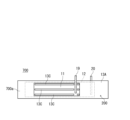
- FIG. 1 is a vertical cross-sectional view schematically showing a secondary battery according to an embodiment of the present disclosure.
- FIG. 3 is a diagram schematically showing an example of the configuration of an electrode group.
- FIG. 7 is a diagram schematically showing another example of the configuration of an electrode group.
- (a) It is a top view showing an example of a first base material and a negative electrode arranged on the first base material.
- (b) It is a top view showing an example of a negative electrode composite.
- (a) It is a top view which shows an example of a 2nd base material and the positive electrode arrange
- a top view showing an example of a positive electrode composite It is a top view showing an example of a positive and negative electrode laminated body.
- FIG. 3 is a top view showing an example of a positive electrode with a convex portion. It is a top view which shows still another example of a positive and negative electrode laminated body.
- FIG. 3 is a diagram schematically showing an example of an electrode.
- a secondary battery includes a wound electrode group and a nonaqueous electrolyte.
- the wound electrode group includes a pair of electrodes and a separator disposed between the pair of electrodes.
- a core member is arranged in the hollow of the electrode group.
- At least one of the pair of electrodes has an active material layer and a resin film supporting the active material layer.
- a wound type electrode group in which a core member is disposed in a hollow space will also be referred to as an "electrode group with a core member.”
- An electrode in which an active material layer is supported on a resin film is also referred to as a “resin film-attached electrode.”
- the active material layer may be supported on one surface of the resin film, or may be supported on both surfaces of the resin film.
- the electrode deforms near the hollow part of the electrode group during charging and discharging, causing buckling of the electrode, breakage of the electrode, etc., and deterioration of cycle characteristics.
- the negative electrode of a lithium secondary battery lithium metal precipitates during charging, the volume changes greatly during charging and discharging, and large stress is likely to occur, making it easy to break.
- the negative electrode breaks due to embrittlement of the negative electrode current collector during charging and discharging.
- the secondary battery according to the present disclosure by arranging the core member in the hollow part of the electrode group, deformation of the electrode near the hollow part of the electrode group is suppressed, and breakage of the electrode etc. is suppressed. . Furthermore, by supporting the active material layer on a flexible resin film, stress generated in the electrode during charging and discharging is alleviated, and breakage of the electrode is suppressed.
- the use of a resin film suppresses rupture of the negative electrode due to precipitation of lithium metal and embrittlement of the negative electrode current collector, and the core member can be arranged. This greatly stabilizes the shape of the electrode group. As a result, surface pressure is stably applied to the entire electrode group when lithium metal is deposited at the negative electrode, and the formation of lithium metal dendrites is suppressed. Isolation of lithium metal and increase in negative electrode resistance due to dendrite formation are suppressed.
- the use of a resin film suppresses electrode breakage due to expansion and contraction of the active material, and the arrangement of the core member , the shape of the electrode group is significantly stabilized.
- surface pressure is stably applied to the entire electrode group during charging and discharging, and isolation due to expansion and contraction of the active material is suppressed.
- the resin film is elastically deformed within the electrode group during charging and discharging, the effect of applying surface pressure to the entire electrode group during charging and discharging cycles is likely to be achieved continuously and stably. As a result of the above, the capacity retention rate during cycling is significantly increased.
- the electrode group is usually in contact with the inner surface of the battery can during charging and discharging.
- the shape of the electrode group becomes more stable, and surface pressure can be more stably applied to the entire electrode group.
- the pair of electrodes is a positive electrode and a negative electrode. At least one of the positive electrode and the negative electrode may be an electrode with a resin film. It is preferable that both the positive electrode and the negative electrode are electrodes with resin films.
- the pair of electrodes and the separator each have, for example, a long sheet shape.
- the electrode group with a core member is produced, for example, by winding a pair of electrodes around a core member with a separator in between.
- the winding may be performed after the electrode is placed and fixed on a base material (or a base material having a convex portion) constituting the separator, or may be performed after the convex portion is placed on the electrode.
- a core member at a predetermined position of a laminate of a pair of electrodes and a separator (a positive and negative electrode laminate to be described later), and to fix and wind the core member.
- the fixing method is not particularly limited, and examples include methods using tape, adhesive, heat welding, ultrasonic welding, and the like.
- the core member is fixed to the end of the electrode group on the winding start side, and the core member is fixed and arranged in the hollow of the electrode group.
- the shape of the entire electrode group is further stabilized, and buckling or bending of the electrodes near the hollow portion of the electrode group is significantly suppressed.
- surface pressure is easily applied uniformly to the entire electrode group, and the effect of suppressing the formation of lithium metal dendrites can be stably obtained, and the cycle characteristics are further improved.
- the positive electrode and the negative electrode are wound around a predetermined core through a separator, the core is pulled out, an electrode group with a hollow is obtained, and the core member is inserted into the hollow of the electrode group. It may be produced by doing the following. In this case, although the core member is not fixed to the end of the electrode group on the winding start side, the effect of stabilizing the shape of the electrode group can be obtained by arranging the core member.
- the resin film has good flexibility and can relieve stress generated in the electrodes during charging.
- the above stress is caused by expansion of the active material that stores lithium ions and/or precipitation of lithium metal during charging.
- the stress generated in the electrode by winding can be alleviated. Therefore, breakage of the electrode, etc. can be suppressed.
- resin films are lightweight and easily increase the energy density of the secondary battery. Furthermore, the resin film is difficult to break during roll conveyance and is easy to handle.
- expansion of the negative electrode means that the total volume of the negative electrode and the volume of deposited lithium metal increases.
- the amount of expansion becomes even larger. This tends to cause stress in the negative electrode (an electrode group including the negative electrode). Therefore, in the case of a lithium secondary battery, the effect of stress relaxation by the resin film can be significantly obtained.
- a resin film is a film whose main component is a resin or an organic substance, and 51% by mass or more of the resin film is composed of a resin or an organic substance.
- the resin film may also contain inorganic substances such as inorganic particles.
- the resin film may have a thin layer containing an inorganic substance on at least one surface.
- the resin film may be a stretched film, a nonporous film (a film without holes), or a film having a plurality of regularly arranged holes. The holes may be formed by bombarding the resin film with particles such as sand.
- the resin film may be insulating, electrically conductive, or non-conductive. The form and physical properties of the resin film are not particularly limited.
- the resin contained in the resin film is not particularly limited, but includes, for example, polyester resin, olefin resin, polyphenylene sulfide resin, acrylic resin, polycarbonate resin, polyether ether ketone resin, polyether sulfone resin, polyamide resin, polyimide resin, and nylon resin. , polyvinylidene chloride resin, ethylene-vinyl alcohol copolymer, polyvinyl alcohol resin, polystyrene resin, urethane resin, epoxy resin and the like.
- the resins contained in the resin film may be used alone or in combination of two or more.
- the resin contained in the resin film may have an aromatic ring, or may be a resin containing no fluorine atoms or an olefin resin. When the resin has an aromatic ring (for example, a benzene ring) in its molecule, the affinity between the resin film and the lithium metal layer increases, and the adhesive force between the two increases.
- polyester resin aromatic polyester is preferable, and polyethylene terephthalate, polybutylene terephthalate, polyethylene naphthalate, etc. are preferable.
- the film containing polyethylene terephthalate or the like may be an unstretched film or a biaxially stretched film.
- acrylic resin include polymethyl methacrylate.
- polyimide resin aromatic polyimide is preferred.
- polyamide resin aromatic polyamide (aramid resin) is preferable.
- polypropylene As the olefin resin, polypropylene, polyethylene, etc. are preferable.
- Polypropylene includes unstretched polypropylene, biaxially oriented polypropylene, and the like.
- Polyethylene includes low density polyethylene, medium density polyethylene, high density polyethylene, linear low density polyethylene, metallocene polyethylene, and the like.
- olefin resins include ethylene-vinyl acetate copolymer, ethylene-methyl acrylate copolymer, ethylene-ethyl acrylate copolymer, ethylene-methyl methacrylate copolymer, and ethylene-acrylic acid copolymer. Examples include polymer resins, ethylene-methacrylic acid copolymers, and ionomer resins (for example, those containing at least one of ethylene-acrylic acid copolymers and ethylene-methacrylic acid copolymers).
- Examples of the method for producing the resin film include an extrusion molding method, and examples thereof include a T-die method, an inflation method, and the like.
- the film may be an unstretched film or a stretched film.
- the stretched film may be a uniaxially stretched film or a sequentially (or simultaneously) biaxially stretched film.
- the number of monomers constituting the resin (polymer) is not particularly limited.
- the polymer may be a homopolymer, a copolymer, or a terpolymer.
- the arrangement form of the monomers is not particularly limited, and may be a random copolymer or a block copolymer.
- the resin film may be constructed by laminating two or more types of resin films.
- the resin may be in a crystalline state, an amorphous state obtained by a rapid cooling method, or a mixture of both.
- the surface of the resin film may be subjected to corona treatment or plasma treatment.
- the thickness of the resin film may be, for example, 5 ⁇ m or more and 80 ⁇ m or less, or 5 ⁇ m or more and 30 ⁇ m or less.
- the resin film is usually an insulator and does not have a current collecting function.
- the surface of the resin film may be coated with a base metal layer.
- a resin film whose surface is coated with a base metal layer will also be referred to as a "resin film with a base metal layer.”
- the base metal layer may cover, for example, the area on the surface of the resin film that supports the active material layer (for example, 90% or more of the area) and the area where the electrode lead is attached.
- the base metal layer preferably contains, for example, copper, nickel, chromium, stainless steel, titanium, silver, gold, tin, or the like.
- the base metal layer preferably contains, for example, aluminum, stainless steel, or the like. In this case, the base metal layer can easily ensure corrosion resistance, conductivity, etc., and is difficult to alloy with lithium.
- the thickness of the base metal layer may be, for example, 2 ⁇ m or less, or 1 ⁇ m or less. From the viewpoint of ensuring current collecting property and adhesion, the thickness of the base metal layer may be, for example, 0.001 ⁇ m or more.
- the lithium metal layer may have a current collecting function. That is, the negative electrode may be configured by arranging a lithium metal layer on a resin film. In this case, a base metal layer may be provided on the surface of the resin film at the connection portion with the negative electrode lead.
- the lithium metal layer may be brought into close contact with a resin film having a base metal layer.
- a base metal layer is provided, even if the lithium metal layer is locally reduced during charge/discharge cycles or the lithium metal changes into a lithium compound, resulting in lithium metal becoming isolated in the form of an island, current collection will still be possible. Functional deterioration can be suppressed.
- the base metal layer can be formed by, for example, a vapor phase method such as vapor deposition or sputtering, an electroless plating method, an electrolytic plating method, a laminating method, etc., but the method of forming it is not particularly limited.
- FIG. 11 is a cross-sectional view schematically showing an example of an electrode with a resin film.
- the electrode 50 includes an active material layer 51 and a resin film 52.
- the active material layer 51 is supported on both sides of the resin film 52. Both sides of the resin film 52 may be coated with a base metal layer.
- a base metal layer may be interposed between the active material layer 51 and the resin film 52.
- the active material layer 51 is, for example, a lithium metal layer.
- the material of the core member may be a metal material. Among these, stainless steel and nickel-plated carbon steel are preferred from the viewpoint of strength and durability.
- the material of the core member may be a resin material, such as polyester resin (e.g., polyethylene terephthalate, polyethylene naphthalate, polybutylene terephthalate, etc.), olefin resin (e.g., polyethylene, polypropylene, etc.), polyphenylene sulfide resin.
- acrylic resins for example, polymethyl methacrylate, etc.
- polycarbonate resins for example, polyetheretherketone resins, polyethersulfone resins, polyamide resins (for example, aramid resins), polyimide resins, and the like.
- the resin material of the core member one type may be used alone, or two or more types may be used in combination.
- polypropylene, polyethylene, and polyethylene terephthalate are preferable from the viewpoint of electrolyte resistance and the like.
- the shape of the core member may be selected according to the hollow shape of the electrode group.
- the shape of the core member may be cylindrical, preferably cylindrical.
- the cylindrical core member can be expanded and contracted appropriately, and can play a role like a spring. Furthermore, since the cylindrical core member can accommodate the nonaqueous electrolyte in its hollow space, it is possible to improve the retention of the nonaqueous electrolyte in the electrode group.
- the thickness of the material of the core member in the radial direction may be, for example, 0.1 mm or more and 2 mm or less.
- the outer diameter D1 of the core member is, for example, the same as the inner peripheral surface of the electrode group during initial discharge (for example, the first discharge after purchasing the battery or the discharge after several charging and discharging cycles after manufacturing the battery).
- the size may be such that it makes contact with the core member. In this case, at all times from charging to discharging, moderate pressure is applied from the core member to the electrode group from the inner peripheral side, so deformation of the electrodes is suppressed. Note that during discharge is when the amount of lithium metal precipitated at the negative electrode is small (or when the amount of lithium ions stored at the negative electrode is small), and for example, when the rated capacity of the battery is C, the state of charge ( SOC) is 0.1 ⁇ C or less.
- the outer diameter D1 of the core member and the outer diameter D2 of the electrode group during discharge satisfy the relationship D1/D2 ⁇ 1/4.
- D1/D2 is 1/4 or less, the portion that does not contribute to the charge/discharge reaction can be reduced.
- the pressure applied from the core member toward the inner circumferential surface of the electrode group and the pressure applied from the battery can toward the outer circumferential surface of the electrode group each tend to have appropriate magnitudes, and charging The retention of the non-aqueous electrolyte within the electrode group is easily ensured during discharge.
- the inner diameter of the battery can is determined by the distance between the outer circumferential surface of the electrode group and the battery can during initial discharge (for example, the first discharge after purchasing the battery or the discharge after several charging and discharging cycles after manufacturing the battery).
- the size may be such that it makes contact with the inner circumferential surface.
- appropriate pressure is applied from the battery can to the electrode group from the outer peripheral side at all times from charging to discharging, thereby suppressing deformation of the electrodes.
- the outer diameter D2 of the electrode group is approximately the same size as the inner diameter of the battery can.
- the secondary battery according to the present disclosure may be, for example, a lithium secondary battery (lithium metal secondary battery).
- the lithium secondary battery will be explained in detail below.
- a lithium secondary battery for example, 70% or more of the rated capacity is developed by precipitation and dissolution of lithium metal.
- the movement of electrons in the negative electrode during charging and discharging is mainly due to the precipitation and dissolution of lithium metal in the negative electrode.
- 70 to 100% (for example, 80 to 100% or 90 to 100%) of the movement of electrons (current from another point of view) in the negative electrode during charging and discharging is due to precipitation and dissolution of lithium metal.
- the movement of electrons in the negative electrode of a lithium secondary battery during charging and discharging is mainly due to the intercalation and desorption of lithium ions by the negative electrode active material (such as graphite). is different.
- the open circuit voltage (OCV) of the negative electrode at full charge is, for example, 70 mV or less with respect to lithium metal (lithium dissolution deposition potential).
- Fully charged is a state in which the battery is charged to a state of charge (SOC) of, for example, 0.98 ⁇ C or higher, where C is the rated capacity of the battery.
- SOC state of charge
- the open circuit potential (OCV) of the negative electrode when fully charged can be measured by disassembling a fully charged battery in an argon atmosphere, taking out the negative electrode, and assembling a cell using lithium metal as a counter electrode.
- the non-aqueous electrolyte in the cell may have the same composition as the non-aqueous electrolyte in the disassembled battery.
- the negative electrode of a lithium secondary battery may include a lithium metal layer as an active material layer and a resin film supporting the lithium metal layer.
- the negative electrode may include a base metal layer covering the surface of the resin film, or the base metal layer may be interposed between the lithium metal layer and the resin film.
- the lithium metal layer functions as a negative electrode current collector.
- lithium ions contained in the nonaqueous electrolyte receive electrons on the lithium metal layer to become lithium metal, which is deposited on the surface of the lithium metal layer.
- the lithium metal deposited on the surface of the lithium metal layer is dissolved into the nonaqueous electrolyte as lithium ions by discharge.
- the lithium ion contained in the non-aqueous electrolyte may be derived from a lithium salt added to the non-aqueous electrolyte, or may be supplied from the positive electrode active material by charging, and both of these may be derived from the lithium salt added to the non-aqueous electrolyte. There may be.
- the lithium metal layer may be a layer formed of at least one of lithium metal and lithium alloy.
- the lithium alloy may contain elements such as aluminum, magnesium, indium, zinc, copper, and silver.
- the thickness of the lithium metal layer may be any thickness that can ensure sufficient current collection during discharge, and may be, for example, 1 ⁇ m or more, or 5 ⁇ m or more in a discharge state of 90% or more depth of discharge (DOD). good.
- the thickness of the lithium metal layer may be 40 ⁇ m or less or 30 ⁇ m or less in a discharge state with a depth of discharge of 90% or more.
- a discharge state with a depth of discharge (DOD) of 90% or more is synonymous with a state of charge (SOC) of 0.1 ⁇ C or less, where C is the rated capacity of the battery.
- the relationship between the thickness X of lithium metal deposited on the negative electrode during charging and the distance Y between the positive and negative electrodes during discharging (hereinafter also referred to as "interelectrode distance Y") is Y/X>1.5. It is preferable to satisfy the following.
- the charging time here refers to a time when the amount of lithium metal precipitated at the negative electrode is large, and refers to, for example, a time when the SOC is 0.9 ⁇ C or more.
- the term “during discharge” refers to a time when the amount of lithium metal precipitated at the negative electrode is small, for example, when the SOC is 0.1 ⁇ C or less.
- the above thickness X is the difference between the thickness of the lithium metal layer when the amount of lithium metal precipitated during charging is large and the thickness of the lithium metal layer when the amount of lithium metal precipitated during discharging is small.
- the inter-electrode distance Y can also be said to be the thickness of the separator between the positive and negative electrodes during discharge.
- the thickness of the separator is the total thickness of the plurality of base materials (or a base material and a convex part).
- a negative electrode current collector may be used in place of the resin film (resin film with underlying metal layer) in the negative electrode.
- the material for the negative electrode current collector include copper, copper alloy, oxygen-free copper, and stainless steel.
- the positive electrode includes, for example, a positive electrode active material layer containing a positive electrode active material that inserts and releases lithium ions.
- the positive electrode may include a resin film with a base metal layer that supports the positive electrode active material layer. That is, the positive electrode may include a resin film supporting the positive electrode active material layer and a base metal layer covering the surface of the resin film, and the base metal layer may be interposed between the positive electrode active material layer and the resin film. It's okay.
- the positive electrode active material layer is also referred to as a "positive electrode composite material layer.”
- the positive electrode composite material layer includes a positive electrode active material and, if necessary, components other than the positive electrode active material.
- Components other than the positive electrode active material may include a binder, a conductive material, and the like.
- Known materials can be used as the positive electrode active material, binder, conductive material, and the like.
- the positive electrode is obtained, for example, by applying a positive electrode composite slurry to the surface of a resin film with a base metal layer, drying the coating film, and then rolling it to form a positive electrode composite material layer.
- the positive electrode composite material layer may be formed on only one side of the resin film with a base metal layer, or may be formed on both sides.
- the positive electrode active material examples include lithium-containing transition metal oxides, transition metal fluorides, polyanions, fluorinated polyanions, transition metal sulfides, and the like. Among these, lithium-containing transition metal oxides are preferred because of their low manufacturing cost and high average discharge voltage.
- a lithium-containing transition metal oxide is a composite oxide containing lithium and a metal Me other than lithium, where the metal Me includes at least a transition metal.
- the lithium-containing transition metal oxides composite oxides having a rock salt type (layered rock salt type) crystal structure having a layered structure are preferable in terms of obtaining high capacity.
- the metal Me may include Sc, Ti, V, Cr, Mn, Fe, Co, Ni, Cu, Y, Zr, W, etc. as transition metal elements.
- the lithium-containing transition metal oxide may contain one type of transition metal element, or may contain two or more types of transition metal elements.
- the metal Me desirably contains at least one selected from the group consisting of Co, Ni, and Mn as a transition metal element, and desirably contains at least Ni as a transition metal.
- the lithium-containing transition metal oxide may contain one or more typical elements as necessary. Typical elements include Mg, Al, Ca, Zn, Ga, Ge, Sn, Sb, Pb, Bi, and the like.
- the typical element may be Al or the like. That is, the metal Me may contain Al as an optional component.
- the lithium-containing transition metal oxide is represented by, for example, the general formula (1): Li a Ni b M 1-b O 2 .
- general formula (1) 0.9 ⁇ a ⁇ 1.2 and 0.65 ⁇ b ⁇ 1 are satisfied, and M is Co, Mn, Al, Ti, Fe, Nb, B, Mg, Ca, Sr, At least one element selected from the group consisting of Zr and W.
- mLi/mMe The molar ratio of the total amount mLi of Li in the positive electrode and the negative electrode to the amount mMe of metal Me in the lithium-containing transition metal oxide: mLi/mMe is, for example, 1.2 or less, and may be 1.1 or less.
- a positive electrode current collector may be used in place of the resin film with a base metal layer in the positive electrode.
- the material for the positive electrode current collector include stainless steel, aluminum, aluminum alloy, and titanium.
- the separator may be composed of one base material or a plurality of base materials.
- the base material may be in the form of a sheet.
- the separator may be a laminate of multiple base materials. Alternatively, it may be configured by a laminate of a base material and a convex portion (spacer). A space may be formed between the electrode and the base material by a convex portion (spacer).
- the convex portions may be provided in a plurality of lines along the longitudinal direction of the separator, may be provided in a honeycomb shape, or may be dispersed in a dot shape.
- Examples of the base material include microporous membranes, woven fabrics, nonwoven fabrics, heat-resistant layers, and the like.
- a resin material is used as the material of the microporous membrane, and examples thereof include olefin resin, polyamide resin, polyimide resin, polyester resin, and cellulose resin.
- Examples of the olefin resin include polyethylene, polypropylene, and a copolymer of ethylene and propylene.
- the polyester resin include polyethylene terephthalate.
- glass fibers, cellulose fibers, olefin resins, polyamide resins, polyimide resins, polyester resins, etc. are used as the fiber materials constituting the nonwoven fabric.
- the heat-resistant layer is, for example, a mixed layer of an inorganic material (eg, aluminum oxide, aluminum hydroxide) and a resin material.
- the thickness of the separator is not particularly limited, but is, for example, 10 ⁇ m or more and 80 ⁇ m or less, and may be 20 ⁇ m or more and 70 ⁇ m or less.
- the thickness of the separator is the total thickness of the laminate.
- the separator may include at least one base material selected from the group consisting of microporous sheets (sheet-like microporous membranes) and nonwoven fabric sheets.
- the separator may include a microporous sheet and a heat-resistant layer disposed on at least one surface of the microporous sheet.
- a heat-resistant layer may be disposed between at least one of the positive electrode and the negative electrode and the microporous sheet.
- the heat-resistant layer may be arranged to cover the entire surface of at least one of the microporous sheets, or may be arranged in a line on at least one surface of the microporous sheet.
- a space may be provided between at least one of the positive electrode and the negative electrode and the microporous sheet by the linear heat-resistant layer.
- the heat-resistant layer includes, for example, inorganic particles and a resin material supporting the inorganic particles.
- the resin material include fluorine-containing resins such as polyvinylidene fluoride (PVdF) and polytetrafluoroethylene, and fluorine-containing rubbers such as vinylidene fluoride-tetrafluoroethylene copolymer.
- the inorganic particles include insulating metal oxides. Examples of metal oxides include aluminum oxide (alumina and boehmite), magnesium oxide, titanium oxide (titania), zirconium oxide, silicon oxide (silica), magnesium hydroxide, aluminum hydroxide, and the like.
- the average particle diameter of the inorganic particles is not particularly limited, but is preferably 10 ⁇ m or less, and more preferably 0.1 ⁇ m or more and 2.0 ⁇ m or less.
- the particle size of the inorganic particles is determined by photographing a cross section of the separator with an electron microscope, performing image processing such as binarization to identify the particles, and determining the diameter of an equivalent circle having the same area as the particles.
- the average particle size is determined, for example, by determining the particle diameters of 100 or more particles and averaging them.
- the heat-resistant layer may be formed, for example, by applying a treatment liquid containing a resin material and inorganic particles to the surface of the base material, the positive electrode, or the negative electrode and drying it.
- a treatment liquid containing a resin material and inorganic particles for example, N-methyl-2-pyrrolidone (NMP) is used as the solvent or dispersion medium for the treatment liquid.
- NMP N-methyl-2-pyrrolidone
- the content of the inorganic particles in the heat-resistant layer (treatment liquid) is, for example, 70 parts by mass or more and 100 parts by mass or less per 100 parts by mass of the resin material. In this case, the strength and heat resistance of the heat-resistant layer can be easily ensured.
- the separator may include a base material and a protrusion (spacer).
- a spacer is interposed between at least one of the positive electrode and the negative electrode and the base material.
- a space is formed between at least one of the positive electrode and the negative electrode and the base material.
- the discharge state is a state after a large amount of lithium metal has been dissolved from the negative electrode, and may be, for example, a state of SOC of 0.1 ⁇ C or less.
- the space since the space does not need to be completely filled with lithium metal in the charged state, the space may exist even in the fully charged state, for example.
- the spacer is arranged on at least one selected from the group consisting of the surface of the positive electrode, the surface of the negative electrode, and the surface of the base material.
- the spacer is preferably arranged on the surface of the positive electrode or the surface of the base material on the positive electrode side. In this case, surface pressure from the base material is easily applied to the negative electrode, making it difficult for dendrite-like lithium metal to precipitate, which is advantageous for improving capacity retention during charge/discharge cycles.
- the height of the spacer may be appropriately designed according to the thickness of the sheet-like base material and the distance between the electrode plates.
- the negative electrode has a first region facing the spacer and a second region not facing the spacer.
- the inter-plate space is formed corresponding to the second region.
- the ratio of the area of the first region to the total area of the first region and the second region is not particularly limited, but considering the balance between cycle characteristics and internal resistance, it may be, for example, 5% or more and 30% or less. It may be 5% or more and 20% or less.
- Nonaqueous electrolyte The nonaqueous electrolyte has ionic conductivity (for example, lithium ion conductivity).
- a non-aqueous electrolyte having lithium ion conductivity includes, for example, a non-aqueous solvent, and lithium ions and anions dissolved in the non-aqueous solvent.
- the non-aqueous electrolyte may be in liquid form or gel form.
- a liquid non-aqueous electrolyte is prepared, for example, by dissolving a lithium salt in a non-aqueous solvent. Lithium ions and anions are generated by dissolving the lithium salt in a nonaqueous solvent.
- lithium salt or anion known materials used in nonaqueous electrolytes of lithium secondary batteries can be used. Specific examples include BF 4 ⁇ , ClO 4 ⁇ , PF 6 ⁇ , CF 3 SO 3 ⁇ , CF 3 CO 2 ⁇ , imide anions, oxalate complex anions, and the like.
- the anion of the oxalate complex may contain boron and/or phosphorus.
- the non-aqueous electrolyte may contain one or more of these anions.
- the nonaqueous electrolyte preferably contains at least an anion of an oxalate complex, and more preferably an anion of an oxalate complex containing fluorine.
- the interaction between the fluorine-containing oxalate complex anion and lithium facilitates the uniform precipitation of lithium metal in the form of fine particles. Therefore, local precipitation of lithium metal can be easily suppressed.
- the fluorine-containing oxalate complex anion and other anions may be combined. Other anions may be PF 6 - and/or imide anions.
- anions of the oxalate complex include bisoxalate borate anion, difluorooxalate borate anion (BF 2 (C 2 O 4 ) ⁇ ), PF 4 (C 2 O 4 ) ⁇ , PF 2 (C 2 O 4 ) 2 ⁇ etc., and it is desirable to use at least a difluorooxalate borate anion.
- nonaqueous solvent examples include esters, ethers, nitriles, amides, and halogen-substituted products thereof.
- the non-aqueous electrolyte may contain one or more of these non-aqueous solvents.
- halogen-substituted substances include fluorides and the like.
- esters include carbonate esters and carboxylic acid esters.
- examples of the cyclic carbonate include ethylene carbonate, propylene carbonate, fluoroethylene carbonate (FEC), and the like.
- Examples of chain carbonate esters include dimethyl carbonate (DMC), ethylmethyl carbonate (EMC), diethyl carbonate, and the like.
- Examples of the cyclic carboxylic acid ester include ⁇ -butyrolactone and ⁇ -valerolactone.
- chain carboxylic acid esters include ethyl acetate, methyl propionate, methyl fluoropropionate, and the like.
- Ethers include cyclic ethers and chain ethers.
- the cyclic ether include 1,3-dioxolane, 4-methyl-1,3-dioxolane, tetrahydrofuran, and 2-methyltetrahydrofuran.
- the chain ether include 1,2-dimethoxyethane, diethyl ether, ethyl vinyl ether, methylphenyl ether, benzyl ethyl ether, diphenyl ether, dibenzyl ether, 1,2-diethoxyethane, diethylene glycol dimethyl ether, and the like.
- the concentration of the lithium salt in the nonaqueous electrolyte is, for example, 0.5 mol/L or more and 3.5 mol/L or less.
- the concentration of anions in the non-aqueous electrolyte may be 0.5 mol/L or more and 3.5 mol/L or less.
- the concentration of the anion of the oxalate complex in the nonaqueous electrolyte may be 0.05 mol/L or more and 1 mol/L or less.
- the secondary battery of the present disclosure may be a lithium ion secondary battery.
- the lithium ion secondary battery will be explained in detail below.
- the positive electrode and non-aqueous electrolyte of a lithium ion secondary battery those that can be used as positive electrodes and non-aqueous electrolytes for lithium secondary batteries can be used.
- the positive electrode and the non-aqueous electrolyte those exemplified above can be used.
- the separator a base material that can be used as a separator for lithium secondary batteries can be used.
- the separator may be composed of a first base material 13A and a second base material 13B shown in FIG. 2.
- the negative electrode of a lithium ion secondary battery includes, for example, a negative electrode active material layer (negative electrode composite material layer) containing a negative electrode active material that inserts and releases lithium ions.
- the negative electrode may include a resin film with a base metal layer that supports a negative electrode active material layer. That is, the negative electrode may include a resin film supporting the negative electrode active material layer and a base metal layer covering the surface of the resin film, and the base metal layer may be interposed between the negative electrode active material layer and the resin film. It's okay.
- the negative electrode composite material layer includes a negative electrode active material and, if necessary, components other than the negative electrode active material.
- Components other than the negative electrode active material may include a binder, a thickener, a conductive material, and the like.
- Known materials can be used as the negative electrode active material, binder, conductive material, thickener, and the like.
- the negative electrode is obtained, for example, by applying a negative electrode composite material slurry to the surface of a resin film with a base metal layer, drying the coating film, and then rolling it to form a negative electrode composite material layer.
- the negative electrode composite material layer may be formed on only one side of the resin film with a base metal layer, or may be formed on both sides.
- the negative electrode active material examples include carbonaceous materials, Si-containing materials, and the like.
- the Si-containing material may be a composite particle that includes an ion-conducting phase and a silicon phase dispersed within the ion-conducting phase.
- the ion conductive phase includes at least one selected from the group consisting of a silicate phase, a silicon oxide phase, and a carbon phase.
- the main component (eg 95-100% by weight) of the silicon oxide phase may be silicon dioxide.
- the ion conductive phase is a silicon oxide phase, it is expressed by the formula, for example, SiO x (0.5 ⁇ x ⁇ 1.6).
- the carbon phase may be comprised of amorphous carbon.
- the amorphous carbon may be hard carbon, soft carbon, or other materials.
- Amorphous carbon generally refers to a carbon material in which the average interplanar spacing d002 of (002) planes measured by X-ray diffraction exceeds 0.34 nm.
- the negative electrode may contain one type of negative electrode active material, or may contain a combination of two or more types.
- the negative electrode active material may be a mixture of a carbonaceous material and a Si-containing material.
- the conductive material is, for example, a carbon material.
- the carbon material include carbon black, acetylene black, Ketjen black, carbon nanotubes, and graphite.
- binder examples include fluororesin, polyacrylonitrile, polyimide resin, acrylic resin, polyolefin resin, rubber-like polymer, and the like.
- fluororesin examples include polytetrafluoroethylene and polyvinylidene fluoride.
- thickener examples include anionic cellulose ethers such as carboxymethyl cellulose (CMC).
- a negative electrode current collector may be used in the negative electrode instead of the resin film with a base metal layer.
- the material for the negative electrode current collector include stainless steel, nickel, nickel alloy, copper, copper alloy, and oxygen-free copper.
- FIG. 1 is a vertical cross-sectional view schematically showing a cross section parallel to the winding axis of a secondary battery according to an embodiment of the present disclosure.
- FIG. 2 is a diagram schematically showing an example of the configuration of an electrode group.
- FIG. 3 is a diagram schematically showing another example of the configuration of the electrode group.
- the lithium secondary battery 10 includes a cylindrical battery case, a wound electrode group 14 housed in the battery case, and a non-aqueous electrolyte (not shown).
- the battery case includes a cylindrical battery can 15 with a bottom and a sealing body 16 that seals the opening of the battery can 15.
- the battery can 15 has an annular step 21 formed by partially pressing the side wall from the outside near the opening.
- the sealing body 16 is supported by the opening side surface of the stepped portion 21 .
- a gasket 27 is disposed between the battery can 15 and the sealing body 16, thereby ensuring the hermeticity of the battery can.
- insulating plates 17 and 18 are arranged at both ends of the electrode group 14 in the winding axis direction, respectively.
- the sealing body 16 includes a filter 22, a lower valve body 23, an insulating member 24, an upper valve body 25, and a cap 26.
- the cap 26 is placed on the outside of the battery can 15, and the filter 22 is placed on the inside of the battery can 15.
- the lower valve body 23 and the upper valve body 25 are connected to each other at their central portions, and an insulating member 24 is interposed between their peripheral edges.
- the filter 22 and the lower valve body 23 are connected to each other at their respective peripheral edges.
- the upper valve body 25 and the cap 26 are connected to each other at their respective peripheral edges.
- a ventilation hole is formed in the lower valve body 23.
- the electrode group 14 is composed of a positive electrode 11, a negative electrode 12, and a separator 13.
- the positive electrode 11, the negative electrode 12, and the separator 13 interposed between them are all in the form of a long sheet (or band), and are wound so that their respective width directions are parallel to the winding axis.
- a core member 29 is arranged in the hollow of the electrode group 14 .
- the core member 29 in the illustrated example has a cylindrical shape, its shape is not limited to this, and may be, for example, cylindrical.
- the positive electrode 11 includes, for example, a resin film with a base metal layer and a positive electrode composite material layer supported on both sides of the resin film.
- the positive electrode 11 is electrically connected via a positive electrode lead 19 to a cap 26 that also serves as a positive electrode terminal.
- One end of the positive electrode lead 19 is connected, for example, to a predetermined location where the base metal layer of the positive electrode 11 is exposed.
- the other end of the positive electrode lead 19 extending from the positive electrode 11 passes through a through hole formed in the insulating plate 17 and is welded to the inner surface of the filter 22 .
- the negative electrode 12 includes a resin film (or a resin film with a base metal layer) and a lithium metal layer supported on both sides of the resin film.
- both the positive electrode and the negative electrode are electrodes with a resin film, but either the positive electrode or the negative electrode may be an electrode with a resin film.
- the negative electrode 12 is electrically connected via a negative electrode lead 20 to a battery can 15 that also serves as a negative electrode terminal.
- One end of the negative electrode lead 20 is connected, for example, to a predetermined location of the lithium metal layer of the negative electrode 12 (or a predetermined location where the base metal layer is exposed), and the other end is welded to the inner bottom surface of the battery can 15. .
- the separator 13 is composed of a first base material 13A and a second base material 13B.
- the materials of the first base material and the second base material may be the same or different.
- the thickness of the first base material and the second base material may be the same or different.
- the base material is a microporous sheet
- the current can be interrupted by melting the microporous sheet and closing the pores when the battery temperature rises due to a short circuit or the like.
- the base material is a nonwoven fabric sheet, relatively large voids (pores) in the base material can be ensured.
- the separator 13 of the electrode group 14 may be composed of a first base material 13A and a linear convex portion 13C.
- the first base material 13A may be a microporous sheet
- the convex portions 13C may be a heat-resistant layer.
- the convex portion 13C functions as a spacer, and a space 28 is formed between the positive electrode 11 and the negative electrode 12 by the convex portion 13C.
- the cross-sectional shape of the convex portion 13C is rectangular, but is not limited to this, and may be, for example, trapezoidal.
- the convex portion 13C is provided between the positive electrode 11 and the first base material 13A, but may be provided between the negative electrode 12 and the first base material 13A.
- the plurality of convex portions 13C are They are provided at regular intervals in the width direction of the material 13A. Further, the plurality of convex portions 13C are provided in parallel along the length direction of the first base material 13A.
- the three linear protrusions 13C are arranged in parallel along the length direction of the first base material 13A, but the number of linear protrusions is not limited to this. Further, the arrangement form of the linear convex portions is not limited to this.
- the convex portions may be arranged in a straight line or may be arranged in a curved shape, They may be arranged in a mesh pattern or a dot pattern.
- a space 28 is provided between the positive electrode 11 and the negative electrode 12 by the separator 13 having the convex portion 13C.
- the amount of lithium metal precipitated at the negative electrode is small (the thickness of the lithium metal layer is small), and the space 28 is maintained.
- the amount of lithium metal precipitated at the negative electrode is large (the thickness of the lithium metal layer is large), and the precipitated lithium metal is accommodated in the space 28 while being subjected to the pressing force of the first base material 13A.
- FIG. 2 which includes a separator 13 composed of a first base material 13A and a second base material 13B, will be described with reference to FIGS. 4 to 6. .
- the band-shaped first base material 13A is folded in half along the width direction at the center in the longitudinal direction, and a crease 130a is formed.
- a negative electrode 12 with a negative electrode lead 19 is prepared, and the negative electrode 12 is placed at a predetermined position on the first base material 13A (FIG. 4(a)).
- the end portion of the negative electrode 12 (the portion not facing the positive electrode) is fixed to the first base material 13A using, for example, double-sided tape 12a or the like.
- the first base material 13A is folded in half to obtain a negative electrode composite 200 in which the first base material 13A is arranged on both sides of the negative electrode 12 (FIG. 4(b)).
- the band-shaped second base material 13B is folded in half along the width direction at the center in the longitudinal direction, and a crease 130b is formed.
- a positive electrode 13 with a positive electrode lead 20 is prepared, and the positive electrode 11 is placed at a predetermined position on the second base material 13B (FIG. 5(a)).
- the second base material 13B is folded in half to obtain a positive electrode composite 100 in which the second base material 13B is arranged on both sides of the positive electrode 11 (FIG. 5(b)).
- double-sided tape 11a is pasted along the fold line 130b of the second base material 130b, and the end of the positive electrode 11 is fixed to the second base material 13B with the double-sided tape 11a.
- the positive electrode composite 100 is placed at a predetermined position on the negative electrode composite 200, and the ends of the positive electrode composite 100 are fixed with adhesive tape 100a or the like to obtain a positive and negative electrode laminate 300 (FIG. 6).
- a core member is arranged at one end 200a (on the opposite side of the positive electrode composite 100) in the length direction of the positive and negative electrode stack 300 (negative electrode composite 200) and fixed with tape or the like, so that the negative electrode composite 200 is placed inside (
- the positive and negative electrode composites 300 are wound around the core member so that the positive electrode composites 100 are on the outside.
- FIG. 3 which includes a separator 13 composed of a first base material 13A and a linear convex portion 13C, will be described with reference to FIGS. 7 and 8. .
- a convex portion 13C is arranged on one surface of the first base material 13A (FIG. 7(a)). At this time, the convex portion 13C is not arranged in a portion that will be a fold line 130a (a portion to which the core member is attached), which will be described later.
- the first base material 13A is folded in half and a crease 130a is formed.
- the negative electrode 12 is placed at a predetermined position on the other surface of the first base material 13A (FIG. 7(a)).
- the first base material 13A is folded in half to obtain a negative electrode composite 400 in which the first base material 13A having convex portions 13C on both sides of the negative electrode 12 is arranged (FIG. 4(b)).
- the positive electrode 11 is placed at a predetermined position on the negative electrode composite 400 and fixed with an adhesive tape or the like to obtain a positive and negative electrode laminate 500 (FIG. 8).
- a core member is arranged at one end 500a (surface opposite to the positive electrode 11) in the length direction of the positive and negative electrode laminate 500 (negative electrode composite 400) and fixed with tape etc.
- the positive and negative electrode laminate 500 is wound around the core member so that the positive and negative electrodes are on the outside).
- FIGS. 9 and 10 another example of a method for manufacturing an electrode group with a core member having the configuration shown in FIG. explain.
- Convex portions 13C are arranged on both sides of the positive electrode 11 to obtain a positive electrode composite 600 (FIG. 9). At this time, the convex portion 13C is not arranged in the portion where the positive electrode lead 19 is attached.
- the negative electrode composite 200 shown in FIG. 4(b) is prepared, and the positive electrode composite 600 is placed at a predetermined position on the negative electrode composite 200 and fixed with tape or the like to obtain a positive and negative electrode stack 700 (FIG. 10).
- a core member is placed on one end 700a (on the opposite side of the positive electrode composite 600) of the positive and negative electrode stack 700 (negative electrode composite 200) in the length direction, and fixed with tape or the like, and the negative electrode composite 200 is placed inside (
- the positive and negative electrode composites 700 are wound around the core member so that the positive electrode composites 600 are on the outside.
- a cylindrical lithium secondary battery has been described as an example of a secondary battery, but the secondary battery is not limited to this.
- the shape of the secondary battery is not limited to this, but may be square, and can be appropriately selected from various shapes depending on the purpose and the like. Further, known configurations other than those described above can be used without particular restriction.
- ⁇ Secondary batteries E1, E3 to E12 ⁇ Preparation of resin film for negative electrode or resin film with base metal layer
- a polyethylene terephthalate (PET) film (thickness: 20 ⁇ m) was prepared as a resin film. If necessary, copper base metal layers (thickness: 0.2 ⁇ m) were formed on both sides of the resin film by vacuum evaporation to obtain a resin film with base metal layers.
- a strip-shaped first base material 13A shown in FIG. 4(a) was prepared.
- a sheet-like microporous membrane made of polyethylene was used as the first base material 13A.
- the thickness Y1 of the first base material 13A was 15 ⁇ m or 30 ⁇ m.
- the negative electrode 12 was placed at a predetermined position on the first base material 13A (FIG. 4(a)). At this time, the end portion of the negative electrode 12 (the portion not facing the positive electrode) was fixed to the first base material 13A using double-sided tape 12a. Next, the first base material 13A was folded in half along the fold line 130a to obtain a negative electrode composite 200 in which the first base material 13A was arranged on both sides of the negative electrode 12 (FIG. 4(b)).
- Al foil or resin film with base metal layer for positive electrode An Al foil (thickness: 20 ⁇ m) or a resin film with a base metal layer was prepared.
- the resin film with a base metal layer was obtained by forming an aluminum base metal layer (thickness: 1.5 ⁇ m) on both sides of a polyethylene terephthalate (PET) film (thickness: 20 ⁇ m) using a vacuum evaporation method.
- PET polyethylene terephthalate
- the positive electrode composite slurry is applied to both sides of the resin film with a base metal layer or Al foil, dried, and the coating film is rolled. A laminate having a thickness of 65 ⁇ m was obtained. The laminate was cut into a predetermined electrode size to obtain a strip-shaped positive electrode 11. A positive electrode lead 19 made of Al was attached to a predetermined position of the positive electrode 11 . The filling amount of the positive electrode composite layer (positive electrode active material) was adjusted as appropriate so that the thickness X of lithium metal deposited on the negative electrode during charging was 25 ⁇ m.
- the band-shaped second base material 13B shown in FIG. 5(a) was prepared.
- the second base material 13B a sheet-shaped polyethylene microporous membrane or a sheet-shaped polyester nonwoven fabric was used.
- the thickness Y2 of the second base material 13B was 30 ⁇ m.
- the positive electrode 11 was placed at a predetermined position on the second base material 13B (FIG. 5(a)). At this time, the end of the positive electrode 11 was fixed to the second base material 13B using double-sided tape 11a. Next, the second base material 13B was folded in half along the fold line 130b to obtain a positive electrode composite 100 in which the second base material 13B was disposed on both sides of the positive electrode 11 (FIG. 5(b)).
- a core member made of SUS304 or polypropylene (PP) was prepared.
- the shape of the core member was cylindrical or cylindrical.
- the outer diameter D1 of the core member was 1.8 mm or 3 mm.
- the outer peripheral surface of the electrode group and the inner peripheral surface of the battery can were in contact, and the outer diameter D2 of the electrode group was a value corresponding to the inner diameter (9 mm) of the battery can.
- the ratio of the outer diameter D1 of the core member to the outer diameter D2 of the electrode group during discharge: D1/D2 was 1/3 or 1/5.
- the core member 29 was placed on the end 200a (the surface opposite to the positive electrode composite 100) of the positive and negative electrode stack 300 (negative electrode composite 200) and fixed with tape or the like.
- the positive and negative electrode laminate 300 was wound around the core member 29 with the negative electrode composite 200 on the inside (with the positive electrode composite 100 on the outside).
- the electrode group 14 with the core member 29 was constructed.
- the separator 13 was composed of a first base material 13A and a second base material 13B.
- a positive electrode lead 19 and a negative electrode lead 20 were exposed from one end surface of the columnar wound electrode group.
- the positive electrode 11 was arranged at a predetermined position of the negative electrode composite 200 to constitute a positive and negative electrode stack, and the electrode group 14 with the core member 29 was constructed in the same manner as above.
- the separator 13 was composed of the first base material 13A.
- LiPF 6 and LiBF 2 (C 2 O 4 ) are dissolved in a mixed solvent of 1,2-dimethoxyethane and 1,1,2,2-tetrafluoroethyl-2,2,2-trifluoroethyl ether, respectively, A non-aqueous electrolyte was prepared.
- the concentration of LiPF 6 in the nonaqueous electrolyte was 1 mol/L.
- the concentration of LiBF 2 (C 2 O 4 ) in the nonaqueous electrolyte was 0.1 mol/L.
- the electrode group was inserted into a cylindrical battery can with a bottom, a nonaqueous electrolyte was injected, and the opening of the battery can was sealed with a sealing body. At this time, the positive electrode lead was connected to the sealing body, and the negative electrode lead was connected to the battery can. A gasket was placed between the sealing body and the battery can. In this way, a lithium secondary battery was completed.
- ⁇ Secondary batteries E2, E13, E14 ⁇ Preparation of resin film with base metal layer for negative electrode
- a polyethylene terephthalate (PET) film (thickness: 20 ⁇ m) was prepared as a resin film.
- a copper base metal layer (thickness: 0.2 ⁇ m) was formed on both sides of the resin film by vacuum evaporation. In this way, a resin film with a base metal layer was obtained.
- batteries E2 and E13 a mixture of 50 parts by mass of a silicon-containing material and 50 parts by mass of graphite was used as the negative electrode active material.
- a silicon-containing material was used as the negative electrode active material.
- the composite particle had a conductive layer containing a conductive carbon material on its surface. Note that Gr and Si of the active materials in Tables 2 and 3 represent graphite and silicon-containing materials, respectively.
- the negative electrode composite slurry was applied to both sides of the resin film with the base metal layer, dried, and the coating film was rolled to form negative electrode composite material layers (thickness 50 ⁇ m per side) on both sides of the resin film with the base metal layer.
- a laminate was obtained. The laminate was cut into a predetermined electrode size to obtain a strip-shaped negative electrode 12.
- a negative electrode lead 20 made of Ni was attached to a predetermined position of the negative electrode 12.
- a nonaqueous electrolyte was prepared by dissolving LiPF 6 at a concentration of 1.0 mol/L in a mixed solvent containing ethylene carbonate (EC) and diethyl carbonate (DEC) at a volume ratio of 3:7.
- EC ethylene carbonate
- DEC diethyl carbonate
- Battery E2 was produced in the same manner as Battery E1 except that the above negative electrode and non-aqueous electrolyte were used.
- Batteries E13 and E14 were produced in the same manner as battery E11 except that the above negative electrode and non-aqueous electrolyte were used. Note that the batteries E2, E13, and E14 are lithium ion secondary batteries.
- a spacer ink was prepared by mixing 90 parts by mass of inorganic particles, 10 parts by mass of polyvinylidene fluoride (PVdF) as a resin material, and N-methyl-2-pyrrolidone as a dispersion medium.
- PVdF polyvinylidene fluoride
- Alumina particles (containing alumina with an average particle size of 1 ⁇ m and alumina with an average particle size of 0.1 ⁇ m in a mass ratio of 10/1) were used as the inorganic particles.
- first base material with spacer Arrangement of linear convex portion on first base material
- first base material The same first base material as used in Example 6 was prepared as the first base material.
- a spacer ink was applied to one surface (positive electrode side surface) of the first base material using a dispenser and dried with hot air to form linear protrusions (spacers).
- spacers linear protrusions
- FIG. 7(a) on one surface of the first base material 13A, a total of three mutually connected wires are formed along the length direction at both ends and the center in the width direction.
- Parallel linear convex portions 13C (width 1 mm, height 30 ⁇ m) were formed.
- spacer ink was applied intermittently to the portion that would become the crease 130a (the portion where the core member 29 was attached) so as not to form the convex portion 13C.
- the negative electrode 12 was placed at a predetermined position on the other surface (the side on which the convex portion 13C is not formed) of the first base material 13A (FIG. 7(a)).
- the first base material 13A was folded in half, and the first base material 13A with convex portions 13C was placed on both sides of the negative electrode 12 to obtain a negative electrode composite 400 (FIG. 7(b)).
- the positive electrode 11 was placed at a predetermined position on the negative electrode composite 400 and fixed with tape or the like to obtain a positive and negative electrode laminate 500 (FIG. 8).
- the core member 29 was placed at one end 500a (the surface opposite to the positive electrode 11) of the positive and negative electrode stack 500 (negative electrode composite 400) in the length direction, and fixed with tape or the like.
- the positive and negative electrode laminate 500 was wound around the core member 29 so that the negative electrode composite 400 was on the inside (the positive electrode 11 was on the outside).
- the electrode group 14 with the core member 29 was constructed.
- the separator 13 was composed of a first base material 13A and a linear convex portion 13C.
- Battery E15 was obtained in the same manner as battery E11 except that the electrode group with a core member obtained above was used.
- the negative electrode composite 200 shown in FIG. 4(a) was prepared, and the positive electrode composite 600 was placed at a predetermined position on the negative electrode composite 200 and fixed with tape or the like to obtain a positive and negative electrode laminate 700 (FIG. 10).
- the core member 29 was placed at one end 700a (the surface opposite to the positive electrode composite 600) of the positive and negative electrode stack 700 (negative electrode composite 200) in the length direction, and fixed with tape or the like.
- the positive and negative electrode laminate 700 was wound around the core member 29 so that the negative electrode composite 200 was on the inside (the positive electrode composite 600 was on the outside). In this way, the electrode group 14 with the core member 29 was constructed.
- the separator 13 was composed of a first base material 13A and a linear convex portion 13C.
- Battery E16 was obtained in the same manner as battery E11 except that the electrode group with a core member obtained above was used.
- ⁇ Secondary battery R2 ⁇ Battery R2 was obtained in the same manner as Battery E11, except that the positive and negative electrode laminate was wound using a winding core to obtain an electrode group, and the winding core was removed to obtain an electrode group having a hollow space.
- Battery R3 was obtained in the same manner as battery R1, except that the positive and negative electrode laminate was wound using a winding core to obtain an electrode group, and the winding core was removed to obtain an electrode group having a hollow space.
- the evaluation results are shown in Tables 1 to 3.
- E1 to E16 are examples, and R1 to R3 are comparative examples.
- the cycle capacity retention rate in the table is expressed as a relative value (index) when the cycle capacity retention rate of secondary battery R3 is set to 100.
- Batteries E1 to E16 had higher capacity retention rates than batteries R1 to R3.
- the capacity retention rate increased by about 1% (R3 ⁇ R1) compared to battery R3 using an electrode group with a hollow space.
- the electrolytic copper foil serving as the negative electrode current collector became brittle and broke, so that almost no improvement in capacity retention was observed.
- Battery R2 using a positive electrode and negative electrode including a resin film has a lower capacity retention rate than battery R3 using a positive electrode including a positive electrode current collector (Al foil) and a negative electrode including a negative electrode current collector (electrolytic copper foil). increased by about 6% (R3 ⁇ R2).
- the secondary battery of the present disclosure can be used in electronic devices such as mobile phones, smartphones, and tablet terminals, electric vehicles, hybrid vehicles, plug-in hybrid vehicles, household storage batteries, and the like.
Landscapes
- Chemical & Material Sciences (AREA)
- Chemical Kinetics & Catalysis (AREA)
- Electrochemistry (AREA)
- General Chemical & Material Sciences (AREA)
- Engineering & Computer Science (AREA)
- Materials Engineering (AREA)
- Manufacturing & Machinery (AREA)
- Inorganic Chemistry (AREA)
- Composite Materials (AREA)
- Secondary Cells (AREA)
Abstract
二次電池は、一対の電極と、一対の電極の間に配置されたセパレータと、を有する巻回型の電極群と、電極群の中空に配置された芯部材と、非水電解質と、を具備する。一対の電極の少なくとも一方は、活物質層と、活物質層を担持する樹脂フィルムと、を有する。
Description
本開示は、非水電解質を備える二次電池に関する。
二次電池は、巻回型の電極群と、非水電解質と、を具備する。巻回型の電極群は、正極と負極とを、セパレータを介して渦巻状に巻回することにより構成される。非水電解質二次電池としては、例えば、リチウムイオン二次電池、リチウム二次電池(リチウム金属二次電池)等が挙げられる。リチウムイオン二次電池の負極は、充電時にリチウムイオンを吸蔵し、放電時にリチウムイオンを放出する負極活物質を含む。このような負極活物質としては、黒鉛、ケイ素含有材料等が挙げられる。リチウム二次電池では、充電時に、負極にリチウム金属が析出し、放電時にリチウム金属が溶解し、非水電解質中にリチウムイオンとして放出される。
特許文献1では、正極板、負極板をセパレータを介して軸芯のまわりに捲回して捲回群を作成し、該捲回群を円筒形電池容器に収納した円筒形リチウムイオン電池において、前記捲回群は、前記正極板と前記負極板との間に2枚重ねをしたセパレータを2組用い、該セパレータのそれぞれの先端部分は溶着により一体化されており、該一体化された先端部分のそれぞれは前記軸芯の異なる位置に接合されていることを特徴とする円筒形リチウムイオン電池が提案されている。
二次電池では、サイクル特性の向上が求められている。特許文献1に記載の軸心を巻回型の電極群の中空部に配置すると、充放電時の電極群の中空部近傍での電極の変形による電極の座屈、電極の破断等が抑制され得る。しかし、サイクル特性は依然として不十分である。
本開示の一側面は、一対の電極と、前記一対の電極の間に配置されたセパレータと、を有する巻回型の電極群と、前記電極群の中空に配置された芯部材と、非水電解質と、を具備し、前記一対の電極の少なくとも一方は、活物質層と、前記活物質層を担持する樹脂フィルムと、を有する、二次電池に関する。
本開示によれば、二次電池のサイクル特性を高めることができる。
本発明の新規な特徴を添付の請求の範囲に記述するが、本発明は、構成および内容の両方に関し、本発明の他の目的および特徴と併せ、図面を照合した以下の詳細な説明によりさらによく理解されるであろう。
以下では、本開示の実施形態について例を挙げて説明するが、本開示は以下で説明する例に限定されない。以下の説明では、具体的な数値や材料を例示する場合があるが、本開示の効果が得られる限り、他の数値や材料を適用してもよい。この明細書において、「数値A~数値B」という記載は、数値Aおよび数値Bを含み、「数値A以上で数値B以下」と読み替えることが可能である。以下の説明において、特定の物性や条件などに関する数値の下限と上限とを例示した場合、下限が上限以上とならない限り、例示した下限のいずれかと例示した上限のいずれかを任意に組み合わせることができる。複数の材料が例示される場合、その中から1種を選択して単独で用いてもよく、2種以上を組み合わせて用いてもよい。
本開示の一実施形態に係る二次電池は、巻回型の電極群と、非水電解質と、を具備する。巻回型の電極群は、一対の電極と、一対の電極の間に配置されたセパレータと、を有する。電極群の中空に芯部材が配置されている。一対の電極の少なくとも一方は、活物質層と、活物質層を担持する樹脂フィルムと、を有する。以下、中空に芯部材が配置された巻回型の電極群は、「芯部材付き電極群」とも称する。樹脂フィルムに活物質層が担持された電極は、「樹脂フィルム付き電極」とも称する。活物質層は、樹脂フィルムの一方の表面に担持されていてもよく、樹脂フィルムの両方の表面に担持されていてもよい。
従来、中空を有する巻回型電極群を備える二次電池では、充放電時に電極群の中空部近傍で電極が変形し、電極の座屈、電極の破断等が生じ、サイクル特性が低下する。特にリチウム二次電池の負極は、充電時にリチウム金属が析出し、充放電時の体積変化が大きく、大きな応力が生じ易く、破断等が生じ易い。リチウム二次電池では、負極集電体に電解銅箔等を用いる場合、充放電時に負極集電体の脆化により負極が破断する。
これに対して、本開示に係る二次電池では、電極群の中空に芯部材を配置することで、電極群の中空部近傍での電極の変形が抑制され、電極の破断等が抑制される。また、柔軟性を有する樹脂フィルムに活物質層を担持させることで、充放電時に電極に生じる応力が緩和され、電極の破断等が抑制される。
電極群の中空に芯部材を配置するとともに、活物質層の担持体として樹脂フィルムを用いる場合、サイクル特性が大幅に向上する。
充電時に負極でリチウム金属が析出するリチウム二次電池の場合、樹脂フィルムの使用によりリチウム金属の析出および負極集電体の脆化による負極の破断が抑制されるとともに、芯部材が配置されることにより、電極群の形状が大幅に安定化する。これにより、負極でのリチウム金属の析出時に電極群全体に面圧が安定して加わり、リチウム金属のデンドライトの生成が抑制される。デンドライト生成によるリチウム金属の孤立化、負極抵抗の増大等が抑制される。
また、負極活物質がシリコン含有材料や黒鉛であるリチウムイオン二次電池の場合でも、樹脂フィルムの使用により活物質の膨張収縮による電極の破断が抑制されるとともに、芯部材が配置されることにより、電極群の形状が大幅に安定化する。これにより、充放電時に電極群全体に面圧が安定して加わり、活物質の膨張収縮による孤立化が抑制される。
さらに、樹脂フィルムは充放電時に電極群内で弾性変形するため、充放電サイクル時において、電極群全体に面圧がかかる効果が継続的かつ安定的に得られ易い。
以上のことから、サイクル時の容量維持率が大幅に増大する。
さらに、樹脂フィルムは充放電時に電極群内で弾性変形するため、充放電サイクル時において、電極群全体に面圧がかかる効果が継続的かつ安定的に得られ易い。
以上のことから、サイクル時の容量維持率が大幅に増大する。
電極群は、通常、充放電時において電池缶の内面に接している。電池缶および芯部材により電極群の外周側および内周側が固定されることで、電極群の形状がより安定化し、電極群全体に面圧がより安定して付与され易い。
一対の電極は、正極および負極である。正極および負極の少なくとも一方が、樹脂フィルム付き電極であればよい。正極および負極の両方が、樹脂フィルム付き電極であることが好ましい。
一対の電極およびセパレータは、それぞれ、例えば長尺シート状である。芯部材付き電極群は、例えば、一対の電極をセパレータを介して芯部材の周囲に巻回することにより作製される。巻回は、例えば、セパレータを構成する基材(もしくは凸部を有する基材)に電極を配置し、固定してから行ってもよく、電極に凸部を配置してから行ってもよい。
例えば、一対の電極とセパレータとの積層体(後述の正負極積層体)の所定位置に芯部材を配置し、固定して巻回すること好ましい。固定の方法は特に限定されず、テープ、接着剤、熱溶接、超音波溶接等による方法が挙げられる。この場合、芯部材は電極群の巻き始め側の端部に固定され、電極群の中空に芯部材が固定して配置される。この場合、電極群全体の形状が更に安定化し、電極群の中空部近傍での電極の座屈や折れ曲がりが顕著に抑制される。また、電極群全体に面圧が均一にかかり易く、リチウム金属のデンドライト生成の抑制効果が安定して得られ、サイクル特性が更に向上する。
また、芯部材付き電極群は、正極と負極とをセパレータを介して所定の巻き芯の周囲に巻回し、巻き芯を抜き取り、中空を有する電極群を得、電極群の中空に芯部材を挿入することにより作製してもよい。この場合、芯部材は電極群の巻き始め側の端部に固定されないが、芯部材の配置により電極群の形状安定化の効果は得られる。
(樹脂フィルム)
樹脂フィルムは、良好な柔軟性を有し、充電時に電極に生じる応力を緩和できる。上記の応力は、充電時のリチウムイオンを吸蔵する活物質の膨張および/またはリチウム金属の析出により生じる。また、巻回により電極に生じる応力も緩和できる。よって、電極の破断等を抑制できる。また、樹脂フィルムは、軽量であり、二次電池のエネルギー密度を高めやすい。さらに、樹脂フィルムは、ロール搬送で切れにくく、ハンドリングが容易である。
樹脂フィルムは、良好な柔軟性を有し、充電時に電極に生じる応力を緩和できる。上記の応力は、充電時のリチウムイオンを吸蔵する活物質の膨張および/またはリチウム金属の析出により生じる。また、巻回により電極に生じる応力も緩和できる。よって、電極の破断等を抑制できる。また、樹脂フィルムは、軽量であり、二次電池のエネルギー密度を高めやすい。さらに、樹脂フィルムは、ロール搬送で切れにくく、ハンドリングが容易である。
リチウム二次電池は、充電時に、負極にリチウム金属が析出するため、負極の膨張の程度が大きくなりやすい。ここで、「負極の膨張」とは、負極の体積と析出したリチウム金属の体積との合計の体積が増えることである。特に、リチウム金属がデンドライト状に析出する場合、膨張量はさらに大きくなる。これにより負極(当該負極を含む電極群)に応力が生じやすい。よって、リチウム二次電池の場合、樹脂フィルムによる応力緩和の効果が顕著に得られる。
樹脂フィルムは、樹脂もしくは有機物を主成分とするフィルムであり、樹脂フィルムの51質量%以上が樹脂もしくは有機物で構成されている。樹脂フィルムは、無機粒子のような無機物を含んでもよい。樹脂フィルムは、少なくとも一方の表面に無機物を含む薄い層を有してもよい。樹脂フィルムは、延伸フィルムであってもよく、無孔性フィルム(孔が無いフィルム)であってもよく、規則的に配列した複数の孔を有するフィルムであってもよい。樹脂フィルムに砂等の粒子を衝突させて孔を形成してもよい。樹脂フィルムは、絶縁性を有してもよく、導電性を有してもよく、非導電性であってもよい。樹脂フィルムの形態および物性は特に限定されない。
樹脂フィルムに含まれる樹脂は、特に限定されないが、例えば、ポリエステル樹脂、オレフィン樹脂、ポリフェニレンスルフィド樹脂、アクリル樹脂、ポリカーボネート樹脂、ポリエーテルエーテルケトン樹脂、ポリエーテルスルホン樹脂、ポリアミド樹脂、ポリイミド樹脂、ナイロン樹脂、ポリ塩化ビニリデン樹脂、エチレン-ビニルアルコール共重合体、ポリビニルアルコール樹脂、ポリスチレン樹脂、ウレタン樹脂、エポキシ樹脂等が挙げられる。樹脂フィルムに含まれる樹脂は、1種を単独で用いてもよく、2種以上を組み合わせて用いてもよい。樹脂フィルムに含まれる樹脂は、芳香環を有するものであってもよく、フッ素原子を含まない樹脂やオレフィン樹脂であってもよい。樹脂がその分子内に芳香環(例えばベンゼン環)を有する場合、樹脂フィルムとリチウム金属層との親和性が高くなり、両者間の接着力が向上する。
ポリエステル樹脂としては、芳香族ポリエステルが好ましく、ポリエチレンテレフタレート、ポリブチレンテレフタレート、ポリエチレンナフタレート等が好ましい。ポリエチレンテレフタレート等を含むフィルムは、無延伸フィルムでもよく、二軸延伸フィルムでもよい。アクリル樹脂としては、ポリメタクリル酸メチル等が挙げられる。ポリイミド樹脂としては、芳香族ポリイミドが好ましい。また、ポリアミド樹脂としては芳香族ポリアミド(アラミド樹脂)が好ましい。
オレフィン樹脂としては、ポリプロピレン、ポリエチレン等が好ましい。ポリプロピレンは、無延伸ポリプロピレン、二軸延伸ポリプロピレン等を含む。ポリエチレンは、低密度ポリエチレン、中密度ポリエチレン、高密度ポリエチレン、リニア低密度ポリエチレン、メタロセンポリエチレン等を含む。また、オレフィン樹脂としては、上記以外に、エチレン-酢酸ビニル共重合体、エチレン-メチルアクリレート共重合体、エチレン-エチルアクリレート共重合体、エチレン-メチルメタアクリレート共重合体、エチレン-アクリル酸共重合体、エチレン-メタアクリル酸共重合体、アイオノマー樹脂(例えば、エチレン-アクリル酸共重合体およびエチレン-メタアクリル酸共重合体の少なくとも一方を含むもの)等が挙げられる。
樹脂フィルムの作製法は、押出成形法等が挙げられ、例えば、Tダイ法、インフレーション法等が挙げられる。フィルムは、無延伸フィルムでもよく、延伸フィルムでもよい。延伸フィルムは、一軸延伸フィルムでもよく、逐次(もしくは同時)二軸延伸フィルムでもよい。樹脂(ポリマー)を構成するモノマーの数は特に限定されない。当該ポリマーは、ホモポリマーでもよく、コポリマーでもよく、ターポリマーでもよい。モノマーの配列形態は、特に限定されず、ランダムコポリマーでもよく、ブロックコポリマーでもよい。樹脂フィルムは、2種類以上の樹脂フィルムを積層して構成されていてもよい。樹脂は結晶状態であってもよく、急冷法等により得られた非晶質状態であってもよく、両者の混合状態であってもよい。密着性の向上を目的として、樹脂フィルムの表面は、コロナ処理またはプラズマ処理されていてもよい。
樹脂フィルムの厚みは、リチウム二次電池のエネルギー密度を高める観点から、機械的強度が確保される限り、薄いほど望ましい。樹脂フィルムの厚みは、例えば、5μm以上、80μm以下でもよく、5μm以上、30μm以下でもよい。
(下地金属層)
樹脂フィルムは、通常絶縁体であり、集電機能を有さない。電極の集電機能の確保のため、樹脂フィルムの表面は下地金属層で被覆されていてもよい。以下、表面が下地金属層で被覆された樹脂フィルムを、「下地金属層付き樹脂フィルム」とも称する。下地金属層は、例えば、樹脂フィルム表面の活物質層を担持する領域(例えば当該領域の90%以上)および電極リードを取り付ける領域を覆っていればよい。
樹脂フィルムは、通常絶縁体であり、集電機能を有さない。電極の集電機能の確保のため、樹脂フィルムの表面は下地金属層で被覆されていてもよい。以下、表面が下地金属層で被覆された樹脂フィルムを、「下地金属層付き樹脂フィルム」とも称する。下地金属層は、例えば、樹脂フィルム表面の活物質層を担持する領域(例えば当該領域の90%以上)および電極リードを取り付ける領域を覆っていればよい。
負極の場合、下地金属層は、例えば、銅、ニッケル、クロム、ステンレス鋼、チタン、銀、金、錫等を含むことが好ましい。正極の場合、下地金属層は、例えば、アルミニウム、ステンレス鋼等を含むことが好ましい。この場合、下地金属層は、耐腐食性、導電性等を確保しやすく、リチウムと合金化しにくい。
電池のエネルギー密度の向上の観点から、下地金属層の厚みは、例えば、2μm以下でもよく、1μm以下でもよい。集電性および密着性の確保の観点から、下地金属層の厚みは、例えば、0.001μm以上であってもよい。
リチウム二次電池の負極の場合、リチウム金属層が集電機能を担ってもよい。すなわち、樹脂フィルムにリチウム金属層を配置して負極を構成してもよい。この場合、樹脂フィルムの表面の負極リードとの接続部分に下地金属層を設けてもよい。
また、下地金属層を有する樹脂フィルムにリチウム金属層を密着させてもよい。下地金属層を設ける場合、充放電サイクルの際にリチウム金属層が局所的に減少し、もしくは、リチウム金属がリチウム化合物に変化しすることで、リチウム金属が島状に孤立した場合でも、集電機能の低下を抑制することができる。
下地金属層は、例えば、蒸着、スパッタリングなどの気相法、無電解めっき法、電解めっき法、ラミネート法などで形成することができるが、その形成方法は特に限定されない。
図11は、樹脂フィルム付き電極の一例を模式的に示す断面図である。
電極50は、活物質層51と樹脂フィルム52とを備える。活物質層51は、樹脂フィルム52の両面に担持されている。樹脂フィルム52の両面は下地金属層で被覆されていてもよい。活物質層51と樹脂フィルム52との間に下地金属層が介在していてもよい。活物質層51は、例えば、リチウム金属層である。
電極50は、活物質層51と樹脂フィルム52とを備える。活物質層51は、樹脂フィルム52の両面に担持されている。樹脂フィルム52の両面は下地金属層で被覆されていてもよい。活物質層51と樹脂フィルム52との間に下地金属層が介在していてもよい。活物質層51は、例えば、リチウム金属層である。
(芯部材)
電極群の中空に挿入される芯部材には、相当に大きな圧力が充放電に伴って繰り返し印加される。そのため、芯部材の材料には、相当な機械的強度と耐久性が求められる。芯部材の材料は、金属材料であってもよい。中でも、強度および耐久性の観点から、ステンレス鋼、ニッケルめっき炭素鋼が望ましい。また、芯部材の材料は、樹脂材料であってもよく、例えば、ポリエステル樹脂(例えば、ポリエチレンテレフタレート、ポリエチレンナフタレート、ポリブチレンテレフタレート等)、オレフィン樹脂(例えば、ポリエチレン、ポリプロピレン等)、ポリフェニレンスルフィド樹脂、アクリル樹脂(例えば、ポリメタクリル酸メチル等)、ポリカーボネート樹脂、ポリエーテルエーテルケトン樹脂、ポリエーテルスルホン樹脂、ポリアミド樹脂(例えばアラミド樹脂)、ポリイミド樹脂等が挙げられる。芯部材の樹脂材料は、1種を単独で用いてもよく、2種以上を組み合わせて用いてもよい。中でも、耐電解液性等の観点から、ポリプロピレン、ポリエチレン、ポリエチレンテレフタレートが望ましい。
電極群の中空に挿入される芯部材には、相当に大きな圧力が充放電に伴って繰り返し印加される。そのため、芯部材の材料には、相当な機械的強度と耐久性が求められる。芯部材の材料は、金属材料であってもよい。中でも、強度および耐久性の観点から、ステンレス鋼、ニッケルめっき炭素鋼が望ましい。また、芯部材の材料は、樹脂材料であってもよく、例えば、ポリエステル樹脂(例えば、ポリエチレンテレフタレート、ポリエチレンナフタレート、ポリブチレンテレフタレート等)、オレフィン樹脂(例えば、ポリエチレン、ポリプロピレン等)、ポリフェニレンスルフィド樹脂、アクリル樹脂(例えば、ポリメタクリル酸メチル等)、ポリカーボネート樹脂、ポリエーテルエーテルケトン樹脂、ポリエーテルスルホン樹脂、ポリアミド樹脂(例えばアラミド樹脂)、ポリイミド樹脂等が挙げられる。芯部材の樹脂材料は、1種を単独で用いてもよく、2種以上を組み合わせて用いてもよい。中でも、耐電解液性等の観点から、ポリプロピレン、ポリエチレン、ポリエチレンテレフタレートが望ましい。
芯部材の形状は、電極群の中空の形状に合わせて選択すればよい。芯部材の形状は、円柱状であってもよく、円筒状が好ましい。円筒状の芯部材は適度に膨張と収縮が可能であり、バネのような役割を果たし得る。また、円筒状の芯部材は、中空に非水電解質を収容できるため、電極群の非水電解質の保持性を改善することができる。芯部材の材料の径方向における厚みは、例えば、0.1mm以上、2mm以下であってもよい。
芯部材の外径D1は、例えば、初期の放電時(例えば、電池購入後の初回放電時もしくは電池を製造してから数サイクルの充放電後の放電時)において、電極群の内周面と芯部材とが接触する大きさとしてよい。この場合、充電時から放電時に至る常時において、芯部材から適度な圧力が電極群に内周側から印加されるため、電極の変形が抑制される。
なお、放電時とは、負極でのリチウム金属の析出量が少ないとき(もしくは負極でのリチウムイオンの吸蔵量が少ないとき)であり、例えば、電池の定格容量をCとするときの充電状態(SOC)が0.1×C以下であるときを指す。
なお、放電時とは、負極でのリチウム金属の析出量が少ないとき(もしくは負極でのリチウムイオンの吸蔵量が少ないとき)であり、例えば、電池の定格容量をCとするときの充電状態(SOC)が0.1×C以下であるときを指す。
サイクル特性の向上の観点から、芯部材の外径D1と、放電時の電極群の外径D2とは、D1/D2≦1/4の関係を満たすことが好ましい。D1/D2が1/4以下である場合、充放電反応に寄与しない部分を小さくできる。また、この場合、芯部材から電極群の内周面に向けて印加される圧力、および、電池缶から電極群の外周面に向けて印加される圧力は、それぞれ適度な大きさとなり易く、充放電時において電極群内の非水電解質の保持性が確保され易い。
なお、電池缶の内径は、初期の放電時(例えば、電池購入後の初回放電時もしくは電池を製造してから数サイクルの充放電後の放電時)において、電極群の外周面と電池缶の内周面とが接触する大きさとしてよい。この場合、充電時から放電時に至る常時において、電池缶から適度な圧力が電極群に外周側から印加され、電極の変形が抑制される。この場合、電極群の外径D2は、電池缶の内径とほぼ同じ寸法である。
(リチウム二次電池)
本開示に係る二次電池は、例えば、リチウム二次電池(リチウム金属二次電池)であってもよい。以下、リチウム二次電池について詳述する。
本開示に係る二次電池は、例えば、リチウム二次電池(リチウム金属二次電池)であってもよい。以下、リチウム二次電池について詳述する。
(負極)
リチウム二次電池の負極では、充電時にリチウム金属が析出し、放電時にリチウム金属が溶解する。
リチウム二次電池の負極では、充電時にリチウム金属が析出し、放電時にリチウム金属が溶解する。
リチウム二次電池では、定格容量の例えば70%以上がリチウム金属の析出と溶解により発現する。充電時および放電時の負極における電子の移動は、主に負極におけるリチウム金属の析出および溶解による。具体的には、充電時および放電時の負極における電子の移動(別の観点では電流)の70~100%(例えば80~100%や90~100%)がリチウム金属の析出および溶解による。すなわち、リチウム二次電池の負極は、充電時および放電時の負極における電子の移動が主に負極活物質(黒鉛など)によるリチウムイオンの吸蔵および放出による負極(リチウムイオン二次電池の負極)とは異なる。
充電時に負極においてリチウム金属を析出させる電池では、満充電時における負極の開回路電位(OCV:Open Circuit Voltage)は、リチウム金属(リチウムの溶解析出電位)に対して、例えば70mV以下である。満充電時とは、電池の定格容量をCとするとき、例えば0.98×C以上の充電状態(SOC:State of Charge)となるまで電池を充電した状態である。満充電時における負極の開回路電位(OCV)は、満充電状態の電池をアルゴン雰囲気下で分解して負極を取り出し、リチウム金属を対極としてセルを組み立てて測定すればよい。セルの非水電解質は、分解した電池中の非水電解質と同じ組成でもよい。
リチウム二次電池の負極は、活物質層としてリチウム金属層と、リチウム金属層を担持する樹脂フィルムと、を備えてもよい。負極は、樹脂フィルムの表面を覆う下地金属層を備えてもよく、リチウム金属層と樹脂フィルムとの間に下地金属層が介在していてもよい。
リチウム金属層は、負極集電体として機能する。充電時には、非水電解質に含まれるリチウムイオンが、リチウム金属層上で電子を受け取ってリチウム金属になり、リチウム金属層の表面に析出する。リチウム金属層の表面に析出したリチウム金属は、放電により非水電解質中にリチウムイオンとして溶解する。なお、非水電解質に含まれるリチウムイオは、非水電解質に添加したリチウム塩に由来するものであってもよく、充電により正極活物質から供給されるものであってもよく、これらの双方であってもよい。
リチウム金属層は、リチウム金属もしくはリチウム合金の少なくとも一方で形成された層であればよい。リチウム合金は、リチウム以外に、アルミニウム、マグネシウム、インジウム、亜鉛、銅、銀などの元素を含み得る。
リチウム金属層の厚みは、放電時に十分な集電性を確保できる厚みであればよく、放電深度(DOD:Depth of Discharge)90%以上の放電状態において、例えば、1μm以上でもよく、5μm以上でもよい。一方、リチウム二次電池のエネルギー密度を高める観点から、リチウム金属層の厚みは、放電深度90%以上の放電状態において、40μm以下もしくは30μm以下であってもよい。なお、放電深度(DOD)が90%以上の放電状態とは、電池の定格容量をCとするときの0.1×C以下の充電状態(SOC)と同義である。
充電時に負極に析出するリチウム金属の厚みXと、放電時の正極と負極との間の距離Y(以下、「電極間距離Y」とも称する。)とは、Y/X>1.5の関係を満たすことが好ましい。なお、ここでいう充電時とは、負極でのリチウム金属の析出量が多いときであり、例えば、SOCが0.9×C以上であるときを指す。放電時とは、負極でのリチウム金属の析出量が少ないときであり、例えば、SOCが0.1×C以下であるときを指す。
上記の厚みXは、充電時のリチウム金属の析出量が多いときのリチウム金属層の厚みと、放電時のリチウム金属の析出量が少ないときのリチウム金属層の厚みとの差である。また、電極間距離Yは、放電時の正負極間のセパレータの厚みとも言える。セパレータが複数の基材(もしくは基材および凸部)で構成される場合、セパレータの厚みとは、当該複数の基材(もしくは基材および凸部)の合計厚みである。
上記の厚みXは、充電時のリチウム金属の析出量が多いときのリチウム金属層の厚みと、放電時のリチウム金属の析出量が少ないときのリチウム金属層の厚みとの差である。また、電極間距離Yは、放電時の正負極間のセパレータの厚みとも言える。セパレータが複数の基材(もしくは基材および凸部)で構成される場合、セパレータの厚みとは、当該複数の基材(もしくは基材および凸部)の合計厚みである。
Y/X>1.5を満たす場合、電極間距離が適度に確保され、充電時の析出Liによりセパレータが適度に押され、セパレータが圧縮される(例えば空隙部分が小さくなる)ことにより、析出Liに生じる応力が緩和され易い。Y/X>1.5を満たす場合、樹脂フィルムおよびセパレータにより充放電時に電極に生じる応力が効果的に緩和され、充放電サイクル時に電極群全体に面圧が適度にかかる効果が継続的かつ安定的に得られ易い。よって、デンドライト生成の抑制効果、サイクル特性の向上効果等が顕著に得られる。
正極が樹脂フィルム付き電極である場合、負極では、樹脂フィルム(下地金属層付き樹脂フィルム)の代わりに負極集電体を用いてもよい。負極集電体の材質としては、銅、銅合金、無酸素銅、ステンレス鋼などが例示できる。
(正極)
正極は、例えば、リチウムイオンを吸蔵および放出する正極活物質を含む正極活物質層を備える。正極は、正極活物質層を担持する下地金属層付き樹脂フィルムを備えてもよい。すなわち、正極は、正極活物質層を担持する樹脂フィルムと、樹脂フィルムの表面を覆う下地金属層とを備えてもよく、正極活物質層と樹脂フィルムとの間に下地金属層が介在していてもよい。以下、正極活物質層は、「正極合材層」とも称する。
正極は、例えば、リチウムイオンを吸蔵および放出する正極活物質を含む正極活物質層を備える。正極は、正極活物質層を担持する下地金属層付き樹脂フィルムを備えてもよい。すなわち、正極は、正極活物質層を担持する樹脂フィルムと、樹脂フィルムの表面を覆う下地金属層とを備えてもよく、正極活物質層と樹脂フィルムとの間に下地金属層が介在していてもよい。以下、正極活物質層は、「正極合材層」とも称する。
正極合材層は、正極活物質と、必要に応じて正極活物質以外の成分と、を含む。正極活物質以外の成分は、結着材、導電材等を含んでもよい。正極活物質、結着材、導電材等としては、公知の材料を用い得る。正極は、例えば、下地金属層付き樹脂フィルムの表面に正極合材スラリーを塗布し、塗膜を乾燥させた後、圧延し、正極合材層を形成することにより得られる。正極合材層は、下地金属層付き樹脂フィルムの片面のみに形成されてもよく、両面に形成されてもよい。
正極活物質としては、例えば、リチウム含有遷移金属酸化物、遷移金属フッ化物、ポリアニオン、フッ素化ポリアニオン、遷移金属硫化物等が挙げられる。中でも、製造コストが安く、平均放電電圧が高い点で、リチウム含有遷移金属酸化物が好ましい。
リチウム含有遷移金属酸化物とは、リチウムと、リチウム以外の金属Meとを含み、金属Meが、少なくとも遷移金属を含む複合酸化物である。リチウム含有遷移金属酸化物の中でも、層状構造を有する岩塩型(層状岩塩型)の結晶構造を有する複合酸化物が、高容量を得る点で好ましい。
金属Meは、遷移金属元素として、Sc、Ti、V、Cr、Mn、Fe、Co、Ni、Cu、Y、Zr、W等を含み得る。リチウム含有遷移金属酸化物は、遷移金属元素を一種含んでもよく、二種以上含んでいてもよい。金属Meは、遷移金属元素としてCo、NiおよびMnからなる群より選択される少なくとも1種を含むことが望ましく、少なくとも遷移金属としてNiを含むことが望ましい。
リチウム含有遷移金属酸化物は、必要に応じて1種以上の典型元素を含み得る。典型元素としては、Mg、Al、Ca、Zn、Ga、Ge、Sn、Sb、Pb、Bi等が挙げられる。典型元素はAl等であってもよい。すなわち、金属Meは、任意成分としてAlを含んでもよい。
リチウム含有遷移金属酸化物は、例えば、一般式(1):LiaNibM1-bO2で表される。一般式(1)中、0.9≦a≦1.2および0.65≦b≦1を満たし、Mは、Co、Mn、Al、Ti、Fe、Nb、B、Mg、Ca、Sr、ZrおよびWからなる群より選択される少なくとも1種の元素である。
リチウム含有遷移金属酸化物が有する金属Meの量mMeに対する、正極および負極が有するLiの合計量mLiのモル比:mLi/mMeは、例えば、1.2以下であり、1.1以下でもよい。
負極が樹脂フィルム付き電極である場合、正極では、下地金属層付き樹脂フィルムの代わりに正極集電体を用いてもよい。正極集電体の材質としては、例えば、ステンレス鋼、アルミニウム、アルミニウム合金、チタンなどが例示できる。
(セパレータ)
セパレータには、イオン透過性および絶縁性を有する多孔性の基材が用いられる。セパレータは、1つの基材により構成されていてもよく、複数の基材により構成されていてもよい。基材はシート状であればよい。セパレータは、複数の基材の積層体であってもよい。また、基材および凸部(スペーサ)の積層体により構成されていてもよい。凸部(スペーサ)により電極と基材との間に空間が形成されていてもよい。凸部は、例えば、セパレータの長手方向に沿った複数のライン状に設けてもよく、ハニカム状に設けてもよく、ドット状に分散配置してもよい。
セパレータには、イオン透過性および絶縁性を有する多孔性の基材が用いられる。セパレータは、1つの基材により構成されていてもよく、複数の基材により構成されていてもよい。基材はシート状であればよい。セパレータは、複数の基材の積層体であってもよい。また、基材および凸部(スペーサ)の積層体により構成されていてもよい。凸部(スペーサ)により電極と基材との間に空間が形成されていてもよい。凸部は、例えば、セパレータの長手方向に沿った複数のライン状に設けてもよく、ハニカム状に設けてもよく、ドット状に分散配置してもよい。
基材としては、微多孔膜、織布、不織布、耐熱層等が挙げられる。微多孔膜の材料には、樹脂材料が用いられ、例えば、オレフィン樹脂、ポリアミド樹脂、ポリイミド樹脂、ポリエステル樹脂、セルロース樹脂等が用いられる。オレフィン樹脂としては、ポリエチレン、ポリプロピレン、エチレンとプロピレンとの共重合体等が挙げられる。ポリエステル樹脂としては、ポリエチレンテレフタレート等が挙げられる。不織布を構成する繊維材料には、例えば、ガラス繊維、セルロース繊維、オレフィン樹脂、ポリアミド樹脂、ポリイミド樹脂、ポリエステル樹脂等が用いられる。耐熱層は、例えば、無機材料(例えば、アルミニウム酸化物、アルミニウム水酸化物)と樹脂材料との混合層である。
セパレータの厚みは、特に限定されないが、例えば10μm以上、80μm以下であり、20μm以上、70μm以下であってもよい。セパレータが複数の基材の積層体である場合、セパレータの厚みは、積層体の総厚みである。
セパレータは、微多孔シート(シート状の微多孔膜)および不織布シートからなる群より選択される少なくとも1種の基材を含んでもよい。セパレータは、微多孔シートと、微多孔シートの少なくとも一方の表面に配置された耐熱層とを含んでもよい。電極群において、正極および負極の少なくとも一方と、微多孔シートとの間に、耐熱層が配置されていてもよい。耐熱層は、微多孔シートの少なくとも一方の表面の全てを覆うように配置されていてもよく、微多孔シートの少なくとも一方の表面にライン状に配置されていてもよい。ライン状の耐熱層により、正極および負極の少なくとも一方と微多孔シートとの間に空間が設けられていてもよい。
耐熱層は、例えば、無機粒子と、無機粒子を担持する樹脂材料と、を含む。樹脂材料としては、例えば、ポリフッ化ビニリデン(PVdF)、ポリテトラフルオロエチレン等の含フッ素樹脂、フッ化ビニリデン-テトラフルオロエチレン共重合体等の含フッ素ゴム等が挙げられる。無機粒子は、絶縁性の金属酸化物等が挙げられる。金属酸化物としては、酸化アルミニウム(アルミナやベーマイト)、酸化マグネシウム、酸化チタン(チタニア)、酸化ジルコニウム、酸化ケイ素(シリカ)、水酸化マグネシウム、水酸化アルミニウム等が挙げられる。
無機粒子の平均粒径は、特に限定されないが、例えば10μm以下が好ましく、0.1μm以上、2.0μm以下がより好ましい。無機粒子の粒径は、セパレータの断面を電子顕微鏡で撮影し、二値化などの画像処理を行って粒子を特定し、粒子と同じ面積を有する相当円の直径として求める。平均粒径は、例えば100個以上の粒子の粒径を求め、それらを平均して求める。
耐熱層は、例えば、基材、正極または負極の表面に、樹脂材料および無機粒子を含む処理液を塗布して乾燥させることにより形成してもよい。処理液の溶媒もしくは分散媒には、例えば、N-メチル-2-ピロリドン(NMP)が用いられる。耐熱層(処理液)中の無機粒子の含有量は、例えば、樹脂材料100質量部あたり、70質量部以上、100質量部以下である。この場合、耐熱層の強度および耐熱性が確保され易い。
セパレータは、基材および凸部(スペーサ)を備えていてもよい。この場合、正極および負極の少なくとも一方と基材との間にスペーサが介在する。これにより、正極および負極の少なくとも一方と基材との間に空間が形成される。上記空間の形成により、負極のリチウム金属の析出による体積増加分が吸収され、負極に生じる応力が緩和される。また、当該空間に非水電解質が留まり、液枯れが抑制され、電極群内における反応のばらつき(反応ムラ)が抑制される。凸部は、例えば、樹脂材料を含んでもよく、樹脂材料と無機粒子とを含んでもよい。樹脂材料および無機粒子には、上記の耐熱層で例示するものを用いることができる。
当該空間は、少なくとも放電状態において存在すればよい。ここで、放電状態とは、負極から多くのリチウム金属が溶解した後の状態であり、例えば、0.1×C以下のSOCの状態であってよい。ただし、充電状態において当該空間が完全にリチウム金属で埋められる必要はないため、例えば、満充電状態でも、当該空間が存在し得る。
スペーサは、正極の表面、負極の表面、および基材の表面からなる群より選択される少なくとも1つに配置されている。スペーサは、正極の表面または基材の正極側の表面に配置されていることが好ましい。この場合、負極に基材からの面圧が印加されやすく、デンドライト状のリチウム金属が析出しにくくなり、充放電サイクルにおける容量維持率の向上に有利である。
スペーサの高さは、シート状基材の厚みおよび極板間距離に合わせて適宜設計すればよい。セパレータがスペーサを備える場合、負極は、スペーサと対向する第1領域と、スペーサと対向しない第2領域と、を有する。極板間空間は、第2領域に対応して形成される。第1領域と第2領域との合計面積に対する第1領域の面積の割合は、特に限定されないが、サイクル特性と内部抵抗とのバランスを考慮すると、例えば5%以上、30%以下であってもよく、5%以上、20%以下であってもよい。
(非水電解質)
非水電解質は、イオン伝導性(例えば、リチウムイオン伝導性)を有する。リチウムイオン伝導性を有する非水電解質は、例えば、非水溶媒と、非水溶媒に溶解したリチウムイオンとアニオンとを含んでいる。非水電解質は、液状でもよいし、ゲル状でもよい。液状の非水電解質は、例えば、リチウム塩を非水溶媒に溶解させることにより調製される。リチウム塩が非水溶媒中に溶解することにより、リチウムイオンおよびアニオンが生成する。
非水電解質は、イオン伝導性(例えば、リチウムイオン伝導性)を有する。リチウムイオン伝導性を有する非水電解質は、例えば、非水溶媒と、非水溶媒に溶解したリチウムイオンとアニオンとを含んでいる。非水電解質は、液状でもよいし、ゲル状でもよい。液状の非水電解質は、例えば、リチウム塩を非水溶媒に溶解させることにより調製される。リチウム塩が非水溶媒中に溶解することにより、リチウムイオンおよびアニオンが生成する。
リチウム塩またはアニオンとしては、リチウム二次電池の非水電解質に利用される公知の材料が使用できる。具体的には、BF4
-、ClO4
-、PF6
-、CF3SO3
-、CF3CO2
-、イミド類のアニオン、オキサレート錯体のアニオン等が挙げられる。イミド類のアニオンとしては、N(SO2CF3)2
-、N(CmF2m+1SO2)x(CnF2n+1SO2)y
-(mおよびnは、それぞれ独立して0または1以上の整数であり、xおよびyは、それぞれ独立して0、1または2であり、x+y=2を満たす。)等が挙げられる。オキサレート錯体のアニオンは、ホウ素および/またはリンを含有してもよい。非水電解質は、これらのアニオンを単独で含んでもよく、2種以上含んでもよい。
リチウム金属がデンドライト状に析出するのを抑制する観点から、非水電解質は、少なくともオキサレート錯体のアニオンを含むことが好ましく、中でもフッ素を有するオキサレート錯体アニオンを含むことが望ましい。フッ素を有するオキサレート錯体アニオンとリチウムとの相互作用により、リチウム金属が細かい粒子状で均一に析出し易くなる。そのため、リチウム金属の局所的な析出を抑制しやすくなる。フッ素を有するオキサレート錯体アニオンと他のアニオンとを組み合わせてもよい。他のアニオンは、PF6
-および/またはイミド類のアニオンであってもよい。オキサレート錯体のアニオンとしては、ビスオキサレートボレートアニオン、ジフルオロオキサレートボレートアニオン(BF2(C2O4)-)、PF4(C2O4)-、PF2(C2O4)2
-等が挙げられ、少なくともジフルオロオキサレートボレートアニオンを用いることが望ましい。
非水溶媒としては、例えば、エステル、エーテル、ニトリル、アミド、またはこれらのハロゲン置換体が挙げられる。非水電解質は、これらの非水溶媒を単独で含んでもよく、2種以上含んでもよい。ハロゲン置換体としては、フッ化物等が挙げられる。
エステルとしては、例えば、炭酸エステル、カルボン酸エステル等が挙げられる。環状炭酸エステルとしては、エチレンカーボネート、プロピレンカーボネート、フルオロエチレンカーボネート(FEC)等が挙げられる。鎖状炭酸エステルとしては、ジメチルカーボネート(DMC)、エチルメチルカーボネート(EMC)、ジエチルカーボネート等が挙げられる。環状カルボン酸エステルとしては、γ-ブチロラクトン、γ-バレロラクトン等が挙げられる。鎖状カルボン酸エステルとしては、酢酸エチル、プロピオン酸メチル、フルオロプロピオン酸メチル等が挙げられる。
エーテルとしては、環状エーテルおよび鎖状エーテルが挙げられる。環状エーテルとしては、1,3-ジオキソラン、4-メチル-1,3-ジオキソラン、テトラヒドロフラン、2-メチルテトラヒドロフラン等が挙げられる。鎖状エーテルとしては、1,2-ジメトキシエタン、ジエチルエーテル、エチルビニルエーテル、メチルフェニルエーテル、ベンジルエチルエーテル、ジフェニルエーテル、ジベンジルエーテル、1,2-ジエトキシエタン、ジエチレングリコールジメチルエーテル等が挙げられる。
非水電解質中のリチウム塩の濃度は、例えば、0.5mol/L以上、3.5mol/L以下である。非水電解質中のアニオンの濃度を、0.5mol/L以上、3.5mol/L以下としてもよい。非水電解質中のオキサレート錯体のアニオンの濃度を、0.05mol/L以上、1mol/L以下としてもよい。
(リチウムイオン二次電池)
また、本開示の二次電池は、リチウムイオン二次電池であってもよい。以下、リチウムイオン二次電池について詳述する。
また、本開示の二次電池は、リチウムイオン二次電池であってもよい。以下、リチウムイオン二次電池について詳述する。
リチウムイオン二次電池の正極および非水電解質には、リチウム二次電池の正極および非水電解質で使用可能なものを用いることができる。正極および非水電解質には、上記で例示するものを用いることができる。セパレータには、リチウム二次電池のセパレータで使用可能な基材を用いることができる。セパレータは、図2に示す第1基材13Aおよび第2基材13Bにより構成してもよい。
リチウムイオン二次電池の負極は、例えば、リチウムイオンを吸蔵および放出する負極活物質を含む負極活物質層(負極合材層)を備える。負極は、負極活物質層を担持する下地金属層付き樹脂フィルムを備えてもよい。すなわち、負極は、負極活物質層を担持する樹脂フィルムと、樹脂フィルムの表面を覆う下地金属層とを備えてもよく、負極活物質層と樹脂フィルムとの間に下地金属層が介在していてもよい。
負極合材層は、負極活物質と、必要に応じて負極活物質以外の成分と、を含む。負極活物質以外の成分は、結着材、増粘材、導電材などを含んでもよい。負極活物質、結着材、導電材、増粘材等としては、公知の材料を用い得る。負極は、例えば、下地金属層付き樹脂フィルムの表面に負極合材スラリーを塗布し、塗膜を乾燥させた後、圧延し、負極合材層を形成することにより得られる。負極合材層は、下地金属層付き樹脂フィルムの片面のみに形成されてもよく、両面に形成されてもよい。
負極活物質としては、炭素質材料、Si含有材料などが挙げられる。Si含有材料は、イオン伝導相と、イオン伝導相内に分散しているシリコン相と、を含む複合粒子であってもよい。イオン伝導相は、シリケート相、酸化シリコン相、および炭素相からなる群より選択される少なくとも1種を含む。シリケート相は、リチウムシリケート相であってもよく、リチウムシリケートの組成は、式:Li2zSiO2+z(0<z<2)で表すことができる。安定性、作製容易性、リチウムイオン伝導性等の観点から、zは、0<z<1の関係を満たすことが好ましく、z=1/2がより好ましい。z=1/2を満たすリチウムシリケートは、Li2Si2O5で表すことができる。酸化シリコン相の主成分(例えば95~100質量%)は、二酸化ケイ素であってもよい。イオン伝導相が酸化シリコン相の場合、例えば、SiOX(0.5≦x<1.6)の式で表される。炭素相は、無定形炭素(すなわちアモルファス炭素)で構成されてもよい。無定形炭素は、ハードカーボンでもよいし、ソフトカーボンでもよいし、それ以外でもよい。無定形炭素(アモルファス炭素)とは、一般には、X線回折法により測定される(002)面の平均面間隔d002が0.34nmを超える炭素材料を言う。
炭素質材料としては、例えば、黒鉛、易黒鉛化炭素(ソフトカーボン)、難黒鉛化炭素(ハードカーボン)が挙げられる。負極は、負極活物質を1種含んでいてもよく、2種以上組み合わせて含んでもよい。負極活物質は、炭素質材料とSi含有材料との混合物であってもよい。
導電材は、例えば、炭素材料である。炭素材料としては、カーボンブラック、アセチレンブラック、ケッチェンブラック、カーボンナノチューブ、および黒鉛等が挙げられる。
結着材としては、例えば、フッ素樹脂、ポリアクリロニトリル、ポリイミド樹脂、アクリル樹脂、ポリオレフィン樹脂、ゴム状重合体等が挙げられる。フッ素樹脂としては、ポリテトラフルオロエチレン、ポリフッ化ビニリデン等が挙げられる。増粘材としては、例えば、カルボキシメチルセルロース(CMC)等のアニオン性セルロースエーテルが挙げられる。
正極が樹脂フィルム付き電極である場合、負極では、下地金属層付き樹脂フィルムの代わりに負極集電体を用いてもよい。負極集電体の材質としては、ステンレス鋼、ニッケル、ニッケル合金、銅、銅合金、無酸素銅などが例示できる。
以下、図面を参照して本開示に係る二次電池の実施形態を更に説明する。各図面において、各構成部品の形状または特徴は、必ずしも実際の寸法を反映していないし、必ずしも同一の縮尺比で表されていない。各図面において同一の構成部品には同一の符号を用いる。
図1は、本開示の一実施形態に係る二次電池の巻回軸に平行な断面を模式的に示す縦断面図である。図2は、電極群の構成の一例を模式的に示す図である。図3は、電極群の構成の他の例を模式的に示す図である。
リチウム二次電池10は、円筒形の電池ケースと、電池ケース内に収容された巻回型の電極群14および図示しない非水電解質とを備える。電池ケースは、有底円筒状の電池缶15と、電池缶15の開口を封口する封口体16とで構成される。電池缶15は、開口付近に側壁を部分的に外側からプレスして形成された環状の段部21を有する。封口体16は、段部21の開口側の面により支持される。電池缶15と封口体16との間には、ガスケット27が配置されており、これにより電池缶の密閉性が確保されている。電池缶15内において、電極群14の巻回軸方向の両端部には、絶縁板17、18がそれぞれ配置されている。
封口体16は、フィルタ22、下弁体23、絶縁部材24、上弁体25およびキャップ26を備えている。キャップ26は電池缶15の外側に配置され、フィルタ22は電池缶15の内側に配置される。下弁体23と上弁体25とは、各々の中央部で互いに接続されるとともに、各々の周縁部の間には絶縁部材24が介在している。フィルタ22と下弁体23とは、各々の周縁部で互いに接続している。上弁体25とキャップ26とは、各々の周縁部で互いに接続している。下弁体23には、通気孔が形成されている。異常発熱等により電池缶の内圧が上昇すると、上弁体25がキャップ26側に膨れて、下弁体23から離間する。これにより、下弁体23と上弁体25との電気的接続が遮断される。さらに内圧が上昇すると、上弁体25が破断し、キャップ26に形成された開口からガスが排出される。
電極群14は、正極11、負極12およびセパレータ13とで構成されている。正極11、負極12およびこれらの間に介在するセパレータ13は、いずれも長尺シート状(もしくは帯状)であり、それぞれの幅方向が巻回軸と平行となるように巻回されている。電極群14の中空に芯部材29が配置されている。図示例の芯部材29は円筒状であるが、その形状はこれに限定されず、例えば円柱状であってもよい。
正極11は、例えば、下地金属層付き樹脂フィルムと、当該樹脂フィルムの両面に担持される正極合材層と、を備える。正極11は、正極リード19を介して、正極端子を兼ねるキャップ26と電気的に接続されている。正極リード19の一端は、例えば、正極11の下地金属層が露出する所定箇所に接続されている。正極11から延出した正極リード19の他端は、絶縁板17に形成された貫通孔を通ってフィルタ22の内側面に溶接されている。
負極12は、樹脂フィルム(もしくは下地金属層付き樹脂フィルム)と、当該樹脂フイルムの両面に担持されるリチウム金属層と、を備える。本実施形態では、正極および負極の両方が、樹脂フィルム付き電極であるが、正極および負極のいずれか一方が樹脂フイルム付き電極であってもよい。負極12は、負極リード20を介して負極端子を兼ねる電池缶15と電気的に接続されている。負極リード20の一端は、例えば、負極12におけるリチウム金属層の所定箇所(もしくは下地金属層が露出する所定箇所)に接続されており、他端は、電池缶15の内底面に溶接されている。
図2に示すように、セパレータ13は第1基材13Aおよび第2基材13Bで構成されている。第1基材および第2基材の材料は、互いに同じであってもよく、異なっていてもよい。第1基材および第2基材の厚みは、互いに同じであってもよく、異なっていてもよい。基材が微多孔シートである場合、短絡等による電池温度の上昇時に微多孔シートが溶融して孔が閉塞することで電流を遮断できる。基材が不織布シートである場合、基材の空隙(孔)を比較的大きく確保できる。
また、図3に示すように、電極群14のセパレータ13は、第1基材13Aとライン状凸部13Cとで構成されていてもよい。この場合、第1基材13Aは微多孔シートであってもよく、凸部13Cは耐熱層であってもよい。凸部13Cは、スペーサとして機能し、凸部13Cにより、正極11と負極12との間に空間28が形成される。
凸部13Cの断面形状は、断面形状が矩形であるが、これに限定されず、例えば、台形などであってよい。凸部13Cは、正極11と第1基材13Aとの間に設けられているが、負極12と第1基材13Aとの間に設けられてもよい。
図7に示すように、電極群の構成前において、ライン状凸部13Cを有する第1基材13Aを、その主面の法線方向から見たとき、複数の凸部13Cは、第1基材13Aの幅方向において一定の間隔で設けられている。また、複数の凸部13Cは、第1基材13Aの長さ方向に沿って平行に設けられている。
本実施形態では、3本のライン状凸部13Cが、第1基材13Aの長さ方向に沿って平行に配置されているが、ライン状凸部の本数はこれに限定されない。また、ライン状凸部の配置形態はこれに限定されない。電極群の構成前において凸部を有する第1基材を、その主面の法線方向から見たとき、凸部は直線状に配置されていてもよく曲線状に配置されていてもよく、網目状、ドット状に配置されていてもよい。
凸部13Cを有するセパレータ13により、正極11と負極12との間に空間28が設けられている。放電状態では、負極でのリチウム金属の析出量が少なく(リチウム金属層の厚みが小さく)、空間28が保持されている。一方、充電状態では、負極でのリチウム金属の析出量が多く(リチウム金属層の厚みが大きく)、析出したリチウム金属は第1基材13Aの押圧力を受けながら空間28に収容される。
リチウム金属は、正極11とセパレータ13との間の空間28に収容されるため、充放電サイクルにおいてリチウム金属の析出に伴う電極群の見かけの体積変化が低減される。よって、負極に付与される応力も抑制される。また、負極12と第1基材13Aとの間に収容されたリチウム金属には第1基材13Aから圧力が加わるため、リチウム金属の析出状態が制御され、リチウム金属が孤立しにくく、充放電効率の低下が抑制される。
以下、第1基材13Aおよび第2基材13Bで構成されるセパレータ13を備える、図2に示す構成の芯部材付き電極群の作製方法の一例を、図4~6を参照しながら説明する。
帯状の第1基材13Aを、長手方向の中央部において幅方向に沿って2つ折りにし、折り目130aを付ける。負極リード19付き負極12を準備し、第1基材13Aの所定位置に負極12を配置する(図4(a))。このとき、例えば、両面テープ12a等を用いて、負極12の端部(正極と対向しない部分)を第1基材13Aに固定する。第1基材13Aを2つ折りにし、負極12の両面に第1基材13Aが配置された負極複合体200を得る(図4(b))。
帯状の第2基材13Bを、長手方向の中央部において幅方向に沿って2つ折りにし、折り目130bを付ける。正極リード20付き正極13を準備し、第2基材13Bの所定位置に正極11を配置する(図5(a))。第2基材13Bを2つ折りにし、正極11の両面に第2基材13Bが配置された正極複合体100を得る(図5(b))。このとき、例えば、第2基材130bの折り目130bに沿って両面テープ11aを貼り付けておき、両面テープ11aにより正極11の端部を第2基材13Bに固定する。
負極複合体200の所定位置に正極複合体100を配置し、正極複合体100の端部を粘着テープ100a等で固定し、正負極積層体300を得る(図6)。正負極積層体300(負極複合体200)の長さ方向の一端部200a(正極複合体100と反対側の表面)に芯部材を配置し、テープ等で固定し、負極複合体200が内側(正極複合体100が外側)になるように正負極複合体300を芯部材に巻き付ける。
以下、第1基材13Aおよびライン状凸部13Cで構成されるセパレータ13を備える、図3に示す構成の芯部材付き電極群の作製方法の一例を、図7~8を参照しながら説明する。
第1基材13Aの一方の表面に凸部13Cを配置する(図7(a))。このとき、後述の折り目130aとなる部分(芯部材を取り付ける部分)には凸部13Cを配置しない。第1基材13Aを2つ折りにし、折り目130aを付ける。第1基材13Aの他方の表面の所定位置に負極12を配置する(図7(a))。第1基材13Aを2つ折りにし、負極12の両面に凸部13Cを有する第1基材13Aが配置された負極複合体400を得る(図4(b))。
負極複合体400の所定位置に正極11を配置し、粘着テープ等で固定し、正負極積層体500を得る(図8)。正負極積層体500(負極複合体400)の長さ方向の一端部500a(正極11と反対側の表面)に芯部材を配置し、テープ等で固定し、負極複合体400が内側(正極11が外側)になるように正負極積層体500を芯部材に巻き付ける。
以下、第1基材13Aおよびライン状凸部13Cで構成されるセパレータ13を備える、図3に示す構成の芯部材付き電極群の作製方法の他の例を、図9~10を参照しながら説明する。
正極11両面に凸部13Cを配置し、正極複合体600を得る(図9)。このとき、正極リード19を取り付ける部分には凸部13Cを配置しない。図4(b)の負極複合体200を準備し、負極複合体200の所定位置に正極複合体600を配置し、テープ等で固定し、正負極積層体700を得る(図10)。正負極積層体700(負極複合体200)の長さ方向の一端部700a(正極複合体600と反対側の表面)に芯部材を配置し、テープ等で固定し、負極複合体200が内側(正極複合体600が外側)になるように正負極複合体700を芯部材に巻き付ける。
図示例では、二次電池の一例として円筒形のリチウム二次電池について説明したが、二次電池はこれに限定されない。二次電池の形状等はこれに限らず、角型でもよく、用途等に応じて各種形状から適宜選択することができる。また、上記以外の公知の構成を特に制限なく利用できる。
[実施例]
以下、本開示に係る二次電池を実施例および比較例に基づいて更に具体的に説明する。ただし、本開示は以下の実施例に限定されるものではない。
以下、本開示に係る二次電池を実施例および比較例に基づいて更に具体的に説明する。ただし、本開示は以下の実施例に限定されるものではない。
《二次電池E1、E3~E12》
(負極用の樹脂フィルムまたは下地金属層付き樹脂フィルムの準備)
樹脂フィルムとしてポリエチレンテレフタレート(PET)製のフィルム(厚み20μm)を準備した。必要に応じて、樹脂フィルムの両面に銅の下地金属層(厚み0.2μm)を真空蒸着法により形成し、下地金属層付き樹脂フィルムを得た。
(負極用の樹脂フィルムまたは下地金属層付き樹脂フィルムの準備)
樹脂フィルムとしてポリエチレンテレフタレート(PET)製のフィルム(厚み20μm)を準備した。必要に応じて、樹脂フィルムの両面に銅の下地金属層(厚み0.2μm)を真空蒸着法により形成し、下地金属層付き樹脂フィルムを得た。
(負極の作製)
露点がマイナス30℃以下のドライ雰囲気中で、樹脂フィルムまたは下地金属層付き樹脂フィルムの両面にリチウム金属箔(厚み30μm)を圧着し、樹脂フィルムまたは下地金属層付き樹脂フィルムの両面にリチウム金属層を配置した。このようにして負極12を作製し、負極12の所定位置にNi製の負極リード20を取り付けた。なお、リチウム金属層は、充電時の厚み55μmおよび放電時の厚み30μmであった。すなわち、充電時に負極に析出するリチウム金属の厚みXは、25μmであった。
露点がマイナス30℃以下のドライ雰囲気中で、樹脂フィルムまたは下地金属層付き樹脂フィルムの両面にリチウム金属箔(厚み30μm)を圧着し、樹脂フィルムまたは下地金属層付き樹脂フィルムの両面にリチウム金属層を配置した。このようにして負極12を作製し、負極12の所定位置にNi製の負極リード20を取り付けた。なお、リチウム金属層は、充電時の厚み55μmおよび放電時の厚み30μmであった。すなわち、充電時に負極に析出するリチウム金属の厚みXは、25μmであった。
(第1基材の準備)
図4(a)の帯状の第1基材13Aを準備した。第1基材13Aには、シート状のポリエチレン製の微多孔膜を用いた。第1基材13Aの厚みY1は、15μmまたは30μmとした。
図4(a)の帯状の第1基材13Aを準備した。第1基材13Aには、シート状のポリエチレン製の微多孔膜を用いた。第1基材13Aの厚みY1は、15μmまたは30μmとした。
(負極複合体の作製)
第1基材13Aの所定位置に負極12を配置した(図4(a))。このとき、両面テープ12aを用いて負極12の端部(正極と対向しない部分)を第1基材13Aに固定した。次に、折り目130aに沿って第1基材13Aを2つ折りにして、負極12の両面に第1基材13Aが配置された負極複合体200を得た(図4(b))。
第1基材13Aの所定位置に負極12を配置した(図4(a))。このとき、両面テープ12aを用いて負極12の端部(正極と対向しない部分)を第1基材13Aに固定した。次に、折り目130aに沿って第1基材13Aを2つ折りにして、負極12の両面に第1基材13Aが配置された負極複合体200を得た(図4(b))。
(正極用のAl箔または下地金属層付き樹脂フィルムの準備)
Al箔(厚み20μm)または下地金属層付き樹脂フィルムを準備した。下地金属層付き樹脂フィルムは、真空蒸着法により、ポリエチレンテレフタレート(PET)製のフィルム(厚み20μm)の両面にアルミニウムの下地金属層(厚み1.5μm)を形成して得られた。
Al箔(厚み20μm)または下地金属層付き樹脂フィルムを準備した。下地金属層付き樹脂フィルムは、真空蒸着法により、ポリエチレンテレフタレート(PET)製のフィルム(厚み20μm)の両面にアルミニウムの下地金属層(厚み1.5μm)を形成して得られた。
(正極合材スラリーの調製)
正極活物質95質量部に、アセチレンブラック2.5質量部と、ポリフッ化ビニリデン2.5質量部とを加え、さらにN-メチル-2-ピロリドンを適量加えて撹拌し、正極合材スラリーを調製した。正極活物質には、Li、Ni、CoおよびAl(Ni、CoおよびAlの合計に対するLiのモル比は1.0)を含有し、層状構造を有する岩塩型のリチウム含有遷移金属酸化物を用いた。
正極活物質95質量部に、アセチレンブラック2.5質量部と、ポリフッ化ビニリデン2.5質量部とを加え、さらにN-メチル-2-ピロリドンを適量加えて撹拌し、正極合材スラリーを調製した。正極活物質には、Li、Ni、CoおよびAl(Ni、CoおよびAlの合計に対するLiのモル比は1.0)を含有し、層状構造を有する岩塩型のリチウム含有遷移金属酸化物を用いた。
(正極の作製)
正極合材スラリーを、下地金属層付き樹脂フィルムまたはAl箔の両面に塗布し、乾燥し、塗膜を圧延し、下地金属層付き樹脂フィルムまたはAl箔の両面に正極合材層(片面当たりの厚み65μm)が形成された積層体を得た。積層体を所定の電極サイズに切断し、帯状の正極11を得た。正極11の所定位置にAl製の正極リード19を取り付けた。充電時に負極に析出するリチウム金属の厚みXが25μmとなるように、正極合材層(正極活物質)の充填量を適宜調整した。
正極合材スラリーを、下地金属層付き樹脂フィルムまたはAl箔の両面に塗布し、乾燥し、塗膜を圧延し、下地金属層付き樹脂フィルムまたはAl箔の両面に正極合材層(片面当たりの厚み65μm)が形成された積層体を得た。積層体を所定の電極サイズに切断し、帯状の正極11を得た。正極11の所定位置にAl製の正極リード19を取り付けた。充電時に負極に析出するリチウム金属の厚みXが25μmとなるように、正極合材層(正極活物質)の充填量を適宜調整した。
(第2基材の準備)
E6~E12では、図5(a)の帯状の第2基材13Bを準備した。第2基材13Bには、シート状のポリエチレン製の微多孔膜またはシート状のポリエステル製の不織布を用いた。第2基材13Bの厚みY2は、30μmとした。
E6~E12では、図5(a)の帯状の第2基材13Bを準備した。第2基材13Bには、シート状のポリエチレン製の微多孔膜またはシート状のポリエステル製の不織布を用いた。第2基材13Bの厚みY2は、30μmとした。
(正極複合体の作製)
第2基材13Bの所定位置に正極11を配置した(図5(a))。このとき、両面テープ11aを用いて正極11の端部を第2基材13Bに固定した。次に、折り目130bに沿って第2基材13Bを2つ折りにして、正極11の両面に第2基材13Bが配置された正極複合体100を得た(図5(b))。
第2基材13Bの所定位置に正極11を配置した(図5(a))。このとき、両面テープ11aを用いて正極11の端部を第2基材13Bに固定した。次に、折り目130bに沿って第2基材13Bを2つ折りにして、正極11の両面に第2基材13Bが配置された正極複合体100を得た(図5(b))。
(芯部材の準備)
SUS304製またはポリプロピレン(PP)製の芯部材を準備した。芯部材の形状は、円柱状または円筒状とした。芯部材の外径D1は、1.8mmまたは3mmとした。
初期の放電時において、電極群の外周面と電池缶の内周面が接触し、電極群の外径D2は電池缶の内径(9mm)に相当する値であった。放電時の電極群の外径D2に対する芯部材の外径D1の比:D1/D2は、1/3または1/5であった。
SUS304製またはポリプロピレン(PP)製の芯部材を準備した。芯部材の形状は、円柱状または円筒状とした。芯部材の外径D1は、1.8mmまたは3mmとした。
初期の放電時において、電極群の外周面と電池缶の内周面が接触し、電極群の外径D2は電池缶の内径(9mm)に相当する値であった。放電時の電極群の外径D2に対する芯部材の外径D1の比:D1/D2は、1/3または1/5であった。
(芯部材付き電極群の作製)
E6~E12では、図6に示すように、負極複合体200の所定位置に正極複合体100を配置し、正極複合体100の端部を粘着テープ100a等で固定し、正負極積層体300を得た。
E6~E12では、図6に示すように、負極複合体200の所定位置に正極複合体100を配置し、正極複合体100の端部を粘着テープ100a等で固定し、正負極積層体300を得た。
正負極積層体300(負極複合体200)の端部200a(正極複合体100と反対側側の表面)に芯部材29を配置し、テープ等で固定した。負極複合体200を内側にして(正極複合体100を外側にして)、正負極積層体300を芯部材29に巻き付けた。このようにして、芯部材29付き電極群14を構成した。電極群14において、セパレータ13は、第1基材13Aおよび第2基材13Bで構成された。柱状の巻回型電極群の一方の端面から正極リード19および負極リード20を露出させた。
E1、E3~E5では、負極複合体200の所定位置に正極11を配置して正負極積層体を構成し、上記と同様にして、芯部材29付き電極群14を構成した。電極群14において、セパレータ13は第1基材13Aで構成された。
(非水電解質の調製)
1,2-ジメトキシエタンおよび1,1,2,2-テトラフルオロエチル-2,2,2-トリフルオロエチルエーテルの混合溶媒にLiPF6およびLiBF2(C2O4)をそれぞれ溶解させて、非水電解質を調製した。非水電解質中のLiPF6の濃度は1モル/Lとした。非水電解質中のLiBF2(C2O4)の濃度は0.1モル/Lとした。
1,2-ジメトキシエタンおよび1,1,2,2-テトラフルオロエチル-2,2,2-トリフルオロエチルエーテルの混合溶媒にLiPF6およびLiBF2(C2O4)をそれぞれ溶解させて、非水電解質を調製した。非水電解質中のLiPF6の濃度は1モル/Lとした。非水電解質中のLiBF2(C2O4)の濃度は0.1モル/Lとした。
(電池の組み立て)
電極群を有底円筒状の電池缶に挿入し、非水電解質を注入し、封口体で電池缶の開口を封口した。このとき、正極リードを封口体に接続し、負極リードを電池缶に接続した。封口体と電池缶との間にガスケットを配置した。このようにして、リチウム二次電池を完成させた。
電極群を有底円筒状の電池缶に挿入し、非水電解質を注入し、封口体で電池缶の開口を封口した。このとき、正極リードを封口体に接続し、負極リードを電池缶に接続した。封口体と電池缶との間にガスケットを配置した。このようにして、リチウム二次電池を完成させた。
《二次電池E2、E13、E14》
(負極用の下地金属層付き樹脂フィルムの準備)
樹脂フィルムとしてポリエチレンテレフタレート(PET)製のフィルム(厚み20μm)を準備した。真空蒸着法により、樹脂フィルムの両面に銅の下地金属層(厚み0.2μm)を形成した。このようにして、下地金属層付き樹脂フィルムを得た。
(負極用の下地金属層付き樹脂フィルムの準備)
樹脂フィルムとしてポリエチレンテレフタレート(PET)製のフィルム(厚み20μm)を準備した。真空蒸着法により、樹脂フィルムの両面に銅の下地金属層(厚み0.2μm)を形成した。このようにして、下地金属層付き樹脂フィルムを得た。
(負極合材スラリーの調製)
負極活物質97.5質量部に、カルボキシメチルセルロースナトリウム(CMC-Na)1質量部と、スチレン-ブタジエンゴム(SBR)1.5質量部とを加え、さらに水を適量加えて攪拌し、負極合材スラリーを調製した。
負極活物質97.5質量部に、カルボキシメチルセルロースナトリウム(CMC-Na)1質量部と、スチレン-ブタジエンゴム(SBR)1.5質量部とを加え、さらに水を適量加えて攪拌し、負極合材スラリーを調製した。
電池E2、E13では、負極活物質として、ケイ素含有材料50質量部と黒鉛50質量部との混合物を用いた。電池E14では、負極活物質としてケイ素含有材料を用いた。ケイ素含有材料には、酸化シリコン相内にシリコン相が分散している複合粒子(SiOx粒子)を用いた。複合粒子は、その表面に導電性炭素材料を含む導電層を有していた。
なお、表2および表3中の活物質のGrおよびSiは、それぞれ黒鉛およびケイ素含有材料を表す。
なお、表2および表3中の活物質のGrおよびSiは、それぞれ黒鉛およびケイ素含有材料を表す。
(負極の作製)
負極合材スラリーを、下地金属層付き樹脂フィルムの両面に塗布し、乾燥し、塗膜を圧延し、下地金属層付き樹脂フィルムの両面に負極合材層(片面当たりの厚み50μm)が形成された積層体を得た。積層体を所定の電極サイズに切断し、帯状の負極12を得た。負極12の所定位置にNi製の負極リード20を取り付けた。
負極合材スラリーを、下地金属層付き樹脂フィルムの両面に塗布し、乾燥し、塗膜を圧延し、下地金属層付き樹脂フィルムの両面に負極合材層(片面当たりの厚み50μm)が形成された積層体を得た。積層体を所定の電極サイズに切断し、帯状の負極12を得た。負極12の所定位置にNi製の負極リード20を取り付けた。
(非水電解質の調製)
エチレンカーボネート(EC)とジエチルカーボネート(DEC)とを3:7の体積比で含む混合溶媒にLiPF6を1.0mol/Lの濃度で溶解して非水電解液を調製した。
エチレンカーボネート(EC)とジエチルカーボネート(DEC)とを3:7の体積比で含む混合溶媒にLiPF6を1.0mol/Lの濃度で溶解して非水電解液を調製した。
上記負極および非水電解質を用いた以外、電池E1と同様にして電池E2を作製した。上記負極および非水電解質を用いた以外、電池E11と同様にして電池E13、E14を作製した。なお、電池E2、E13、E14は、リチウムイオン二次電池である。
《二次電池E15》
(スペーサインクの調製)
無機粒子90質量部と、樹脂材料であるポリフッ化ビニリデン(PVdF)10質量部と、分散媒N-メチル-2-ピロリドンとを混合して、スペーサインクを調製した。無機粒子には、アルミナ粒子(平均粒径1μmのアルミナと平均粒径0.1μmのアルミナとを10/1の質量比で含む)を用いた。
(スペーサインクの調製)
無機粒子90質量部と、樹脂材料であるポリフッ化ビニリデン(PVdF)10質量部と、分散媒N-メチル-2-ピロリドンとを混合して、スペーサインクを調製した。無機粒子には、アルミナ粒子(平均粒径1μmのアルミナと平均粒径0.1μmのアルミナとを10/1の質量比で含む)を用いた。
(スペーサ付き第1基材の作製:ライン状凸部の第1基材への配置)
第1基材には、実施例6で用いた第1基材と同じものを準備した。ディスペンサを用いて第1基材の一方の表面(正極側の表面)にスペーサインクを塗布し、熱風乾燥させて、ライン状凸部(スペーサ)を形成した。具体的には、図7(a)に示すように、第1基材13Aの一方の表面において、その幅方向の両端部および中央部に、その長さ方向に沿って、合計3本の互いに平行なライン状凸部13C(幅1mm、高さ30μm)を形成した。このとき、折り目130aとなる部分(芯部材29を取り付ける部分)には凸部13Cを形成しないように、スペーサインクを間欠的に塗布した。
第1基材には、実施例6で用いた第1基材と同じものを準備した。ディスペンサを用いて第1基材の一方の表面(正極側の表面)にスペーサインクを塗布し、熱風乾燥させて、ライン状凸部(スペーサ)を形成した。具体的には、図7(a)に示すように、第1基材13Aの一方の表面において、その幅方向の両端部および中央部に、その長さ方向に沿って、合計3本の互いに平行なライン状凸部13C(幅1mm、高さ30μm)を形成した。このとき、折り目130aとなる部分(芯部材29を取り付ける部分)には凸部13Cを形成しないように、スペーサインクを間欠的に塗布した。
(芯部材付き電極群の作製)
第1基材13Aの他方の表面(凸部13Cを形成しない側)の所定位置に負極12を配置した(図7(a))。第1基材13Aを2つ折りにして、負極12の両面に凸部13C付き第1基材13Aを配置し、負極複合体400を得た(図7(b))。負極複合体400の所定位置に正極11を配置し、テープ等で固定し、正負極積層体500を得た(図8)。正負極積層体500(負極複合体400)の長さ方向の一端部500a(正極11と反対側の表面)に芯部材29を配置し、テープ等で固定した。負極複合体400が内側(正極11が外側)になるように正負極積層体500を芯部材29に巻き付けた。このようにして、芯部材29付き電極群14を構成した。電極群14において、セパレータ13は、第1基材13Aおよびライン状凸部13Cで構成された。
第1基材13Aの他方の表面(凸部13Cを形成しない側)の所定位置に負極12を配置した(図7(a))。第1基材13Aを2つ折りにして、負極12の両面に凸部13C付き第1基材13Aを配置し、負極複合体400を得た(図7(b))。負極複合体400の所定位置に正極11を配置し、テープ等で固定し、正負極積層体500を得た(図8)。正負極積層体500(負極複合体400)の長さ方向の一端部500a(正極11と反対側の表面)に芯部材29を配置し、テープ等で固定した。負極複合体400が内側(正極11が外側)になるように正負極積層体500を芯部材29に巻き付けた。このようにして、芯部材29付き電極群14を構成した。電極群14において、セパレータ13は、第1基材13Aおよびライン状凸部13Cで構成された。
上記で得られた芯部材付き電極群を用いた以外、電池E11と同様にして、電池E15を得た。
《二次電池E16》
(スペーサ付き正極の作製:ライン状凸部の正極への配置)
ディスペンサを用いて正極の両方の表面に上記スペーサインクを塗布し、熱風乾燥させ、ライン状凸部(スペーサ)を形成した。具体的には、図9に示すように、正極11の両方の表面において、その幅方向の両端部および中央部に、その長さ方向に沿って、合計3本の互いに平行なライン状の凸部13C(幅1mm、高さ30μm)を形成した。このとき、正極リード19を取り付ける部分には凸部13Cを形成しないように、スペーサインクを間欠的に塗布した。このようにして、正極11の両面に凸部13Cを配置し、正極複合体600を得た(図9)。
(スペーサ付き正極の作製:ライン状凸部の正極への配置)
ディスペンサを用いて正極の両方の表面に上記スペーサインクを塗布し、熱風乾燥させ、ライン状凸部(スペーサ)を形成した。具体的には、図9に示すように、正極11の両方の表面において、その幅方向の両端部および中央部に、その長さ方向に沿って、合計3本の互いに平行なライン状の凸部13C(幅1mm、高さ30μm)を形成した。このとき、正極リード19を取り付ける部分には凸部13Cを形成しないように、スペーサインクを間欠的に塗布した。このようにして、正極11の両面に凸部13Cを配置し、正極複合体600を得た(図9)。
(芯部材付き電極群の作製)
図4(a)の負極複合体200を準備し、負極複合体200の所定位置に正極複合体600を配置し、テープ等で固定し、正負極積層体700を得た(図10)。正負極積層体700(負極複合体200)の長さ方向の一端部700a(正極複合体600と反対側の表面)に芯部材29を配置し、テープ等で固定した。負極複合体200が内側(正極複合体600が外側)になるように正負極積層体700を芯部材29に巻き付けた。このようにして、芯部材29付き電極群14を構成した。電極群14において、セパレータ13は、第1基材13Aおよびライン状凸部13Cで構成された。
図4(a)の負極複合体200を準備し、負極複合体200の所定位置に正極複合体600を配置し、テープ等で固定し、正負極積層体700を得た(図10)。正負極積層体700(負極複合体200)の長さ方向の一端部700a(正極複合体600と反対側の表面)に芯部材29を配置し、テープ等で固定した。負極複合体200が内側(正極複合体600が外側)になるように正負極積層体700を芯部材29に巻き付けた。このようにして、芯部材29付き電極群14を構成した。電極群14において、セパレータ13は、第1基材13Aおよびライン状凸部13Cで構成された。
上記で得られた芯部材付き電極群を用いた以外、電池E11と同様にして、電池E16を得た。
《二次電池R1》
電解銅箔(厚み12μm)の両面にリチウム金属箔(厚み30μm)を圧着し、負極を得た。正極には、電池E1の正極と同じものを用いた。
上記の負極および正極を用いた以外、電池E11と同様にして、電池R1を得た。
電解銅箔(厚み12μm)の両面にリチウム金属箔(厚み30μm)を圧着し、負極を得た。正極には、電池E1の正極と同じものを用いた。
上記の負極および正極を用いた以外、電池E11と同様にして、電池R1を得た。
《二次電池R2》
正負極積層体を巻き芯を用いて巻回して電極群を得、巻き芯を取り外し、中空を有する電極群を得た以外、電池E11と同様にして、電池R2を得た。
正負極積層体を巻き芯を用いて巻回して電極群を得、巻き芯を取り外し、中空を有する電極群を得た以外、電池E11と同様にして、電池R2を得た。
《二次電池R3》
正負極積層体を巻き芯を用いて巻回して電極群を得、巻き芯を取り外し、中空を有する電極群を得た以外、電池R1と同様にして、電池R3を得た。
正負極積層体を巻き芯を用いて巻回して電極群を得、巻き芯を取り外し、中空を有する電極群を得た以外、電池R1と同様にして、電池R3を得た。
[評価]
得られた各電池について、25℃の環境下で充放電サイクル試験を行った。充放電は、以下の条件で行った。充電と放電との間は、20分間の休止を行った。
得られた各電池について、25℃の環境下で充放電サイクル試験を行った。充放電は、以下の条件で行った。充電と放電との間は、20分間の休止を行った。
(充電)
電池電圧が4.1Vになるまで10mAで定電流充電を行い、その後、電流値が1mAになるまで4.1Vの電圧で定電圧充電を行った。
電池電圧が4.1Vになるまで10mAで定電流充電を行い、その後、電流値が1mAになるまで4.1Vの電圧で定電圧充電を行った。
(放電)
電池電圧が3.0Vになるまで10mAで定電流放電を行った。
電池電圧が3.0Vになるまで10mAで定電流放電を行った。
充放電を100サイクルまで繰り返し行い、1サイクル目の放電容量C1に対する100サイクル目の放電容量C2の割合:(C2/C1)×100を、サイクル容量維持率(%)として求めた。
評価結果を表1~表3に示す。なお、表中、E1~E16は実施例であり、R1~R3は比較例である。表中のサイクル容量維持率は、二次電池R3のサイクル容量維持率を100とするときの相対値(指数)として表した。


電池E1~E16では、電池R1~R3と比べて高い容量維持率が得られた。
芯部材付き電極群を用いた電池R1では、中空を有する電極群を用いた電池R3に対して、容量維持率が約1%増大した(R3→R1)。電池R1では、芯部材を配置したが、負極集電体である電解銅箔の脆化により箔切れを生じたため、容量維持率の改善はほとんど見られなかった。樹脂フィルムを含む正極および負極を用いた電池R2では、正極集電体(Al箔)を含む正極および負極集電体(電解銅箔)を含む負極を用いた電池R3に対して、容量維持率が約6%程度増大した(R3→R2)。
これに対して、樹脂フィルム付き電極を用いて芯部材付き電極群を構成した電池E11では、電池R3に対して、容量維持率が約41%程度に大幅に増大した(R3→E11)。電池E11では、柔軟性を有する樹脂フィルムの使用および芯部材の配置により、充放電サイクル時に電極群全体に面圧が安定的に付与され、リチウム金属のデンドライト生成が抑制され、容量維持率が大幅に増大した。
本開示の二次電池は、携帯電話、スマートフォン、タブレット端末のような電子機器、電気自動車、ハイブリッド自動車、プラグインハイブリッド自動車、家庭用蓄電池等に用いることができる。
本発明を現時点での好ましい実施態様に関して説明したが、そのような開示を限定的に解釈してはならない。種々の変形および改変は、上記開示を読むことによって本発明に属する技術分野における当業者には間違いなく明らかになるであろう。したがって、添付の請求の範囲は、本発明の真の精神および範囲から逸脱することなく、すべての変形および改変を包含する、と解釈されるべきものである。
10 リチウム二次電池
11 正極
12 負極
13 セパレータ
13A 第1基材
13B 第2基材
13C ライン状凸部
14 電極群
15 電池缶
16 封口体
17、18 絶縁板
19 正極リード
20 負極リード
21 段部
22 フィルタ
23 下弁体
24 絶縁部材
25 上弁体
26 キャップ
27 ガスケット
28 空間
29 芯部材
50 電極
51 活物質層
52 樹脂フィルム
100、600 正極複合体
200、400 負極複合体
300、500、700 正負極積層体
11 正極
12 負極
13 セパレータ
13A 第1基材
13B 第2基材
13C ライン状凸部
14 電極群
15 電池缶
16 封口体
17、18 絶縁板
19 正極リード
20 負極リード
21 段部
22 フィルタ
23 下弁体
24 絶縁部材
25 上弁体
26 キャップ
27 ガスケット
28 空間
29 芯部材
50 電極
51 活物質層
52 樹脂フィルム
100、600 正極複合体
200、400 負極複合体
300、500、700 正負極積層体
Claims (17)
- 一対の電極と、前記一対の電極の間に配置されたセパレータと、を有する巻回型の電極群と、
前記電極群の中空に配置された芯部材と、
非水電解質と、
を具備し、
前記一対の電極の少なくとも一方は、活物質層と、前記活物質層を担持する樹脂フィルムと、を有する、二次電池。 - 前記一対の電極は、正極および負極であり、
前記負極は、
前記活物質層として、リチウムイオンを吸蔵および放出する負極活物質を含む負極活物質層と、
前記負極活物質層を担持する前記樹脂フィルムと、
前記樹脂フィルムの表面を覆う下地金属層と、を有し、
前記負極活物質層と前記樹脂フィルムとの間に前記下地金属層が介在している、請求項1に記載の二次電池。 - 前記一対の電極は、正極および負極であり、
前記負極では、充電時にリチウム金属が析出し、放電時に前記リチウム金属が溶解し、
前記負極は、
前記活物質層としてリチウム金属層と、
前記リチウム金属層を担持する前記樹脂フィルムと、を有する、請求項1に記載の二次電池。 - 前記負極は、前記樹脂フィルムの表面を覆う下地金属層を有し、
前記リチウム金属層と前記樹脂フィルムとの間に前記下地金属層が介在している、請求項3に記載の二次電池。 - 充電時に前記負極に析出するリチウム金属の厚みXと、放電時の前記正極と前記負極との間の距離Yとは、Y/X>1.5の関係を満たす、請求項3または4に記載の二次電池。
- 前記正極は、
前記活物質層として、リチウムイオンを吸蔵および放出する正極活物質を含む正極活物質層と、
前記正極活物質層を担持する前記樹脂フィルムと、
前記樹脂フィルムの表面を覆う下地金属層と、を有し、
前記正極活物質層と前記樹脂フィルムとの間に前記下地金属層が介在している、請求項2~5のいずれか1項に記載の二次電池。 - 前記芯部材は、前記電極群の巻き始め側の端部に固定されている、請求項1~6のいずれか1項に記載の二次電池。
- 前記樹脂フィルムは、ポリエステル樹脂、オレフィン樹脂、ポリフェニレンスルフィド樹脂、アクリル樹脂、ポリカーボネート樹脂、ポリエーテルエーテルケトン樹脂、ポリエーテルスルホン樹脂、ポリアミド樹脂、ポリイミド樹脂、ナイロン樹脂、ポリ塩化ビニリデン樹脂、エチレン-ビニルアルコール共重合体、ポリビニルアルコール樹脂、ポリスチレン樹脂、ウレタン樹脂、およびエポキシ樹脂からなる群より選択される少なくとも1種を含む、請求項1~7のいずれか1項に記載の二次電池。
- 前記ポリエステル樹脂は、ポリエチレンテレフタレート、ポリブチレンテレフタレート、およびポリエチレンナフタレートからなる群より選択される少なくとも1種を含む、請求項8に記載の二次電池。
- 前記オレフィン樹脂は、ポリエチレンおよびポリプロピレンからなる群より選択される少なくとも1種を含む、請求項8または9に記載の二次電池。
- 前記セパレータは、微多孔シートおよび不織布シートからなる群より選択される少なくとも1種の基材を含む、請求項1~10のいずれか1項に記載の二次電池。
- 前記セパレータは、複数の前記基材により構成されている、請求項11に記載の二次電池。
- 前記セパレータは、微多孔シートと、前記微多孔シートの少なくとも一方の表面に配置された耐熱層とを含み、
前記電極群において、前記一対の電極の少なくとも一方と、前記微多孔シートとの間に、前記耐熱層が配置されている、請求項1~10のいずれか1項に記載の二次電池。 - 前記セパレータは、基材および凸部の積層体により構成され、
前記凸部により、前記一対の電極の少なくとも一方と、前記基材との間に、空間が設けられている、請求項3~5のいずれか1項に記載の二次電池。 - 前記芯部材の材料が、金属材料または樹脂材料である、請求項1~14のいずれか1項に記載の二次電池。
- 前記芯部材の形状が、円筒状である、請求項1~15のいずれか1項に記載の二次電池。
- 前記芯部材の外径D1と、放電時の前記電極群の外径D2とは、D1/D2≦1/4の関係を満たす、請求項1~16のいずれか1項に記載の二次電池。
Applications Claiming Priority (2)
| Application Number | Priority Date | Filing Date | Title |
|---|---|---|---|
| JP2022-060745 | 2022-03-31 | ||
| JP2022060745 | 2022-03-31 |
Publications (1)
| Publication Number | Publication Date |
|---|---|
| WO2023190871A1 true WO2023190871A1 (ja) | 2023-10-05 |
Family
ID=88202889
Family Applications (1)
| Application Number | Title | Priority Date | Filing Date |
|---|---|---|---|
| PCT/JP2023/013184 WO2023190871A1 (ja) | 2022-03-31 | 2023-03-30 | 二次電池 |
Country Status (1)
| Country | Link |
|---|---|
| WO (1) | WO2023190871A1 (ja) |
Citations (7)
| Publication number | Priority date | Publication date | Assignee | Title |
|---|---|---|---|---|
| JPH05314984A (ja) * | 1992-05-12 | 1993-11-26 | Yuasa Corp | 電池用集電体 |
| JPH09213338A (ja) * | 1996-01-30 | 1997-08-15 | Shin Kobe Electric Mach Co Ltd | 電池及びリチウムイオン二次電池 |
| JP2003031224A (ja) * | 2001-04-10 | 2003-01-31 | Toyo Kohan Co Ltd | 二次電池用の軽量集電体 |
| JP2005108835A (ja) * | 2003-09-26 | 2005-04-21 | Samsung Sdi Co Ltd | リチウムイオン二次電池 |
| JP2009087889A (ja) * | 2007-10-03 | 2009-04-23 | Sony Corp | 耐熱絶縁層付きセパレータ及び非水電解質二次電池 |
| JP2016134296A (ja) * | 2015-01-20 | 2016-07-25 | 株式会社カネカ | セパレータ一体型電極、及びその製造方法、並びにこれを有するリチウムイオン二次電池 |
| WO2019087709A1 (ja) * | 2017-10-30 | 2019-05-09 | パナソニックIpマネジメント株式会社 | 非水電解質二次電池及びその製造方法 |
-
2023
- 2023-03-30 WO PCT/JP2023/013184 patent/WO2023190871A1/ja unknown
Patent Citations (7)
| Publication number | Priority date | Publication date | Assignee | Title |
|---|---|---|---|---|
| JPH05314984A (ja) * | 1992-05-12 | 1993-11-26 | Yuasa Corp | 電池用集電体 |
| JPH09213338A (ja) * | 1996-01-30 | 1997-08-15 | Shin Kobe Electric Mach Co Ltd | 電池及びリチウムイオン二次電池 |
| JP2003031224A (ja) * | 2001-04-10 | 2003-01-31 | Toyo Kohan Co Ltd | 二次電池用の軽量集電体 |
| JP2005108835A (ja) * | 2003-09-26 | 2005-04-21 | Samsung Sdi Co Ltd | リチウムイオン二次電池 |
| JP2009087889A (ja) * | 2007-10-03 | 2009-04-23 | Sony Corp | 耐熱絶縁層付きセパレータ及び非水電解質二次電池 |
| JP2016134296A (ja) * | 2015-01-20 | 2016-07-25 | 株式会社カネカ | セパレータ一体型電極、及びその製造方法、並びにこれを有するリチウムイオン二次電池 |
| WO2019087709A1 (ja) * | 2017-10-30 | 2019-05-09 | パナソニックIpマネジメント株式会社 | 非水電解質二次電池及びその製造方法 |
Similar Documents
| Publication | Publication Date | Title |
|---|---|---|
| EP3188298B1 (en) | Stacked cell and production method for same | |
| TWI536637B (zh) | 鋰電極以及含彼之鋰二次電池組 | |
| KR101985041B1 (ko) | 내열 절연층을 갖는 세퍼레이터 | |
| US7927740B2 (en) | Battery pack and vehicle | |
| KR101689496B1 (ko) | 비수 전해액계 이차 전지 | |
| US20160276652A1 (en) | Electrode, nonaqueous electrolyte battery, and battery pack | |
| WO2022045127A1 (ja) | リチウム二次電池 | |
| JP2013201077A (ja) | 非水電解質二次電池 | |
| WO2017007015A1 (ja) | 非水電解質電池及び電池パック | |
| JPWO2020059131A1 (ja) | 電池及び電池パック | |
| JP2012156405A (ja) | 蓄電デバイス | |
| KR101863399B1 (ko) | 축전 디바이스 | |
| WO2022000307A1 (zh) | 一种电化学装置及包含该电化学装置的电子装置 | |
| JP7212629B2 (ja) | リチウムイオン二次電池 | |
| JPH11144764A (ja) | リチウムイオン二次電池およびリチウムイオン二次電池を用いた組電池 | |
| JP2018137133A (ja) | 非水電解質蓄電素子用の負極、非水電解質蓄電素子及び非水電解質蓄電素子用の負極の製造方法 | |
| WO2022209601A1 (ja) | リチウム二次電池 | |
| WO2022224872A1 (ja) | リチウム二次電池 | |
| JP6083289B2 (ja) | リチウムイオン二次電池 | |
| US20230041063A1 (en) | Electrode Rolling Apparatus and Electrode Rolling Method | |
| WO2023190871A1 (ja) | 二次電池 | |
| JP2015210848A (ja) | 非水電解質二次電池 | |
| CN112840477B (zh) | 非水电解质二次电池用负极以及使用了该负极的非水电解质二次电池 | |
| JP7040364B2 (ja) | 非水電解質二次電池 | |
| JP2018078029A (ja) | 負極及び非水電解質蓄電素子 |
Legal Events
| Date | Code | Title | Description |
|---|---|---|---|
| 121 | Ep: the epo has been informed by wipo that ep was designated in this application |
Ref document number: 23780879 Country of ref document: EP Kind code of ref document: A1 |