WO2023189794A1 - 金属張積層板及びその製造方法 - Google Patents
金属張積層板及びその製造方法 Download PDFInfo
- Publication number
- WO2023189794A1 WO2023189794A1 PCT/JP2023/010803 JP2023010803W WO2023189794A1 WO 2023189794 A1 WO2023189794 A1 WO 2023189794A1 JP 2023010803 W JP2023010803 W JP 2023010803W WO 2023189794 A1 WO2023189794 A1 WO 2023189794A1
- Authority
- WO
- WIPO (PCT)
- Prior art keywords
- layer
- adhesive layer
- metal
- inorganic filler
- clad laminate
- Prior art date
- Legal status (The legal status is an assumption and is not a legal conclusion. Google has not performed a legal analysis and makes no representation as to the accuracy of the status listed.)
- Ceased
Links
Images


Classifications
-
- B—PERFORMING OPERATIONS; TRANSPORTING
- B32—LAYERED PRODUCTS
- B32B—LAYERED PRODUCTS, i.e. PRODUCTS BUILT-UP OF STRATA OF FLAT OR NON-FLAT, e.g. CELLULAR OR HONEYCOMB, FORM
- B32B15/00—Layered products comprising a layer of metal
- B32B15/04—Layered products comprising a layer of metal comprising metal as the main or only constituent of a layer, which is next to another layer of the same or of a different material
- B32B15/08—Layered products comprising a layer of metal comprising metal as the main or only constituent of a layer, which is next to another layer of the same or of a different material of synthetic resin
- B32B15/082—Layered products comprising a layer of metal comprising metal as the main or only constituent of a layer, which is next to another layer of the same or of a different material of synthetic resin comprising vinyl resins; comprising acrylic resins
-
- B—PERFORMING OPERATIONS; TRANSPORTING
- B32—LAYERED PRODUCTS
- B32B—LAYERED PRODUCTS, i.e. PRODUCTS BUILT-UP OF STRATA OF FLAT OR NON-FLAT, e.g. CELLULAR OR HONEYCOMB, FORM
- B32B27/00—Layered products comprising a layer of synthetic resin
- B32B27/18—Layered products comprising a layer of synthetic resin characterised by the use of special additives
- B32B27/20—Layered products comprising a layer of synthetic resin characterised by the use of special additives using fillers, pigments, thixotroping agents
-
- B—PERFORMING OPERATIONS; TRANSPORTING
- B32—LAYERED PRODUCTS
- B32B—LAYERED PRODUCTS, i.e. PRODUCTS BUILT-UP OF STRATA OF FLAT OR NON-FLAT, e.g. CELLULAR OR HONEYCOMB, FORM
- B32B27/00—Layered products comprising a layer of synthetic resin
- B32B27/30—Layered products comprising a layer of synthetic resin comprising vinyl (co)polymers; comprising acrylic (co)polymers
-
- B—PERFORMING OPERATIONS; TRANSPORTING
- B32—LAYERED PRODUCTS
- B32B—LAYERED PRODUCTS, i.e. PRODUCTS BUILT-UP OF STRATA OF FLAT OR NON-FLAT, e.g. CELLULAR OR HONEYCOMB, FORM
- B32B7/00—Layered products characterised by the relation between layers; Layered products characterised by the relative orientation of features between layers, or by the relative values of a measurable parameter between layers, i.e. products comprising layers having different physical, chemical or physicochemical properties; Layered products characterised by the interconnection of layers
- B32B7/04—Interconnection of layers
- B32B7/12—Interconnection of layers using interposed adhesives or interposed materials with bonding properties
-
- H—ELECTRICITY
- H05—ELECTRIC TECHNIQUES NOT OTHERWISE PROVIDED FOR
- H05K—PRINTED CIRCUITS; CASINGS OR CONSTRUCTIONAL DETAILS OF ELECTRIC APPARATUS; MANUFACTURE OF ASSEMBLAGES OF ELECTRICAL COMPONENTS
- H05K1/00—Printed circuits
- H05K1/02—Details
- H05K1/03—Use of materials for the substrate
Definitions
- the present invention relates to a method for manufacturing a metal-clad laminate useful as, for example, a circuit board material.
- FPCs flexible printed circuit boards
- demand for circuits is increasing.
- FPCs can be mounted three-dimensionally and with high density even in limited spaces, so their use is expanding, for example, for wiring of electronic devices such as HDDs, DVDs, and smartphones, as well as parts such as cables and connectors. .
- FPC is manufactured by etching the metal layer of a metal clad laminate such as a copper clad laminate (CCL) to form wiring.
- a metal clad laminate such as a copper clad laminate (CCL)
- CCL copper clad laminate
- metal-clad laminates in which highly heat-resistant polyimide is used for the insulating resin layer in contact with the metal foil are commonly used.
- circuit board materials are also becoming more suitable for millimeter wave radar boards, antenna boards, etc. that can support high-speed communication standards. Materials are currently being considered. Among such materials, fluororesins are attracting attention because they have a low dielectric loss tangent and are expected to reduce signal transmission loss.
- Patent Document 1 in the process of manufacturing a composite material layer containing an inorganic filler in a fluororesin matrix, a casting process is performed in which a dispersion composition containing a fluororesin and an inorganic filler is applied to a base material and dried. ing.
- a composite material containing an inorganic filler is formed in a casting process in this way, voids are generated in the coating film.
- Patent Document 1 does not provide a layer that is clearly positioned as an adhesive layer adjacent to the metal layer, and therefore does not consider suppressing the flow of the adhesive layer.
- the present invention aims to eliminate voids in the inorganic filler-containing fluororesin layer and ensure adhesion to the metal foil, while preventing the adhesive layer from flowing out and uneven thickness during thermocompression bonding. purpose.
- the above problem can be solved by focusing on the melting point of the inorganic filler-containing fluororesin layer and considering the relationship between this melting point and the melting point or storage modulus of the adhesive layer. They discovered this and completed the present invention.
- the metal-clad laminate of the present invention is a metal layer; an adhesive layer in direct contact with the metal layer; an inorganic filler-containing fluororesin layer containing an inorganic filler in the fluororesin, which is laminated directly or indirectly on the adhesive layer; It is equipped with
- the adhesive layer and the inorganic filler-containing fluororesin layer are a) or b) as follows: a) When the main resin constituting the adhesive layer is a crystalline resin, the melting point Tm1 of the adhesive layer is higher than the melting point Tm2 of the inorganic filler-containing fluororesin layer; b) When the main resin constituting the adhesive layer is an amorphous resin, the storage elastic modulus E' of the adhesive layer at the melting point Tm2 of the inorganic filler-containing fluororesin layer is 1 x 10 6 Pa or more; The inorganic filler-containing fluororesin layer has a coefficient of thermal expansion (CTE) of 60
- the metal-clad laminate of the present invention was measured using a split cylinder resonator (SCR resonator) after controlling the humidity of the inorganic filler-containing fluororesin layer for 24 hours under constant temperature and humidity conditions of 23° C. and 50% RH.
- the dielectric loss tangent at 60 GHz may be less than 0.0025.
- the metal-clad laminate of the present invention may have a layer structure in which metal layer/adhesive layer/inorganic filler-containing fluororesin layer/adhesive layer/metal layer are laminated in this order.
- the ratio of the thickness of the adhesive layer to the total thickness of the adhesive layer and the inorganic filler-containing fluororesin layer may be within a range of 1 to 25%.
- the method for manufacturing a metal-clad laminate of the present invention is a method for manufacturing the metal-clad laminate described above, comprising: preparing a first laminate in which an adhesive layer is laminated on a metal layer; A second laminate in which the adhesive layer and the dispersion composition layer are laminated on the metal layer is formed by applying a dispersion composition containing an inorganic filler and a fluororesin on the adhesive layer and heat-treating the adhesive layer.
- a step of forming By using two of the second laminates and thermocompression bonding with the dispersion composition layers facing each other, or by using the first laminate and the second laminate, the adhesive layer and the By thermocompression bonding the dispersion composition layers facing each other, a metal-clad laminate having a layer structure in which metal layer/adhesive layer/inorganic filler-containing fluororesin layer/adhesive layer/metal layer is laminated in this order is formed.
- the process of Contains By using two of the second laminates and thermocompression bonding with the dispersion composition layers facing each other, or by using the first laminate and the second laminate, the adhesive layer and the By thermocompression bonding the dispersion composition layers facing each other, a metal-clad laminate having a layer structure in which metal layer/adhesive layer/inorganic filler-containing fluororesin layer/adhesive layer/metal layer is laminated in this order is formed.
- the melting point Tm1 or storage modulus E' of the adhesive layer is taken into consideration in relation to the melting point Tm2 of the inorganic filler-containing fluororesin layer, so the adhesive layer flows out during thermocompression bonding.
- This attempt is made to both eliminate voids in the inorganic filler-containing fluororesin layer and ensure adhesion to the metal foil while preventing the occurrence of thickness unevenness. Therefore, the metal-clad laminate of the present invention is useful as a circuit board material compatible with high-speed communication standards.
- FIG. 1 is a schematic cross-sectional view showing the layer structure of a metal-clad laminate according to a preferred embodiment of the present invention.
- FIG. 2 is an explanatory diagram of the manufacturing process of the metal-clad laminate shown in FIG. 1.
- FIG. 2 is an explanatory diagram of another manufacturing process of the metal-clad laminate shown in FIG. 1.
- FIG. FIG. 2 is an explanatory diagram of still another manufacturing process of the metal-clad laminate of FIG. 1.
- FIG. FIG. 2 is an explanatory diagram of still another manufacturing process of the metal-clad laminate of FIG. 1.
- FIG. 1 is a schematic cross-sectional view showing the layer structure of a metal-clad laminate according to a preferred embodiment of the present invention.
- FIG. 2 is an explanatory diagram of the manufacturing process of the metal-clad laminate shown in FIG. 1.
- FIG. 2 is an explanatory diagram of another manufacturing process of the metal-clad laminate shown in FIG. 1.
- FIG. 2 is an explanatory diagram of still another manufacturing process
- the metal-clad laminate of the present invention includes a metal foil, an adhesive layer in direct contact with the metal foil, and an inorganic filler containing an inorganic filler in a fluororesin that is laminated directly or indirectly on the adhesive layer.
- a fluororesin layer may be any layer other than the above.
- the metal-clad laminate of the present invention satisfies either of the following conditions a) or b).
- the term "main resin” refers to a resin that is contained in an amount exceeding 50% by weight based on all the resin components constituting the adhesive layer (the same applies hereinafter).
- the melting point Tm1 of the adhesive layer is higher than the melting point Tm2 of the inorganic filler-containing fluororesin layer. Because the melting point Tm1 is higher than the melting point Tm2 (Tm1>Tm2), flow out occurs in the adhesive layer when thermocompression bonding is performed at a temperature exceeding the melting point Tm2 in order to eliminate voids in the inorganic filler-containing fluororesin layer. It is possible to effectively prevent the occurrence of uneven thickness.
- the metal-clad laminate it is possible to reduce the voids in the inorganic filler-containing fluororesin layer and ensure adhesion to the metal foil while preventing the adhesive layer from flowing out or causing thickness unevenness.
- the melting point Tm1 is the same as or lower than the melting point Tm2 (Tm1 ⁇ Tm2), flow may occur in the adhesive layer or thickness unevenness may occur during thermocompression bonding at a temperature exceeding the melting point Tm2.
- the melting point Tm1 of the adhesive layer is preferably +5°C or more higher than the melting point Tm2 of the inorganic filler-containing fluororesin layer, and more preferably within the range of +10°C to +50°C.
- the reason why it is defined as the "melting point of the fluororesin layer containing inorganic filler" rather than the “melting point of the fluororesin” is that even if the same fluororesin is used, it is compared to the state without the inorganic filler. This is because when an inorganic filler is contained, the melting point increases due to the influence of the inorganic filler. Therefore, the melting point is not the melting point of the resin alone, but of the "layer” containing the inorganic filler.
- the melting point Tm2 also changes depending on the content of the inorganic filler, and as the amount of the inorganic filler increases, the melting point Tm2 also increases. Therefore, the melting point Tm2 is a physical property value determined depending on the content of the inorganic filler.
- Preferred combinations of resins in which the melting point Tm1 of the crystalline resin constituting the adhesive layer is higher than the melting point Tm2 of the inorganic filler-containing fluororesin layer include, for example: -
- a combination that is a layer of ETFE; Tm2 270-315°C); ⁇
- FEP tetrafluoroethylene-hexafluoropropylene copolymer
- ETFE ethylene-tetrafluoroethylene copolymer
- PFA tetrafluoroethylene-perfluoroalkyl vinyl ether copolymer
- the storage elastic modulus E' of the adhesive layer at the melting point Tm2 of the inorganic filler-containing fluororesin layer is 1 ⁇ 10 6 Pa or more. Since the storage elastic modulus E' of the adhesive layer at the melting point Tm2 is 1 x 10 6 Pa or more, in order to eliminate voids in the inorganic filler-containing fluororesin layer, when thermocompression bonding is performed at a temperature exceeding the melting point Tm2. In addition, it is possible to effectively prevent the adhesive layer from flowing out or becoming uneven in thickness.
- the metal-clad laminate it is possible to reduce the voids in the inorganic filler-containing fluororesin layer and ensure adhesion to the metal foil while preventing the adhesive layer from flowing out or causing thickness unevenness.
- the storage elastic modulus E' of the adhesive layer at the melting point Tm2 is less than 1 x 10 6 Pa, flow may occur in the adhesive layer or thickness unevenness may occur during thermocompression bonding at a temperature exceeding the melting point Tm2. There is a possibility that this may occur.
- the storage elastic modulus E' of the adhesive layer at the melting point Tm2 is preferably 1 ⁇ 10 7 Pa or more.
- Preferred combinations of amorphous resins in which the storage modulus E' at the melting point Tm2 of the inorganic filler-containing fluororesin layer is 1 x 10 6 Pa or more include, for example: -
- the material of the metal layer is not particularly limited, but examples include copper, stainless steel, iron, nickel, beryllium, aluminum, zinc, indium, silver, gold, tin, zirconium, tantalum, titanium, lead, magnesium, manganese, and these. Examples include alloys of Among these, copper or copper alloy is particularly preferred. Note that the material of the wiring layer in the circuit board of this embodiment, which will be described later, is also the same as that of the metal layer.
- the thickness of the metal layer is not particularly limited, but if a metal foil such as copper foil is used, it is preferably 35 ⁇ m or less, more preferably within the range of 5 to 25 ⁇ m. From the viewpoint of production stability and handling properties, the lower limit of the thickness of the metal foil is preferably 5 ⁇ m.
- a metal foil such as copper foil
- the lower limit of the thickness of the metal foil is preferably 5 ⁇ m.
- rolled copper foil or electrolytic copper foil may be used.
- commercially available copper foil can be used as the copper foil.
- the surface roughness of the metal layer is not particularly limited, but from the viewpoint of ensuring both adhesion with the adhesive layer and conductor loss, the ten-point average roughness (Rzjis) is 0.3 to 1.5. It is preferred to have a roughened surface within the range of . Note that the lower the surface roughness of the metal layer, the greater the effect of providing the adhesive layer, so the ten-point average roughness (Rzjis) is more preferably within the range of 0.3 to 1.0. Further, the metal foil may be subjected to a surface treatment using, for example, siding, aluminum alcoholate, aluminum chelate, a silane coupling agent, etc., for the purpose of antirust treatment or improvement of adhesive strength.
- the resin constituting the adhesive layer is not particularly limited, but for example, thermoplastic polyimide, thermoplastic polyamideimide, thermoplastic polyamide, fluororesin, liquid crystal polymer, etc. are preferable.
- the fluororesin the same fluororesin as used in the inorganic filler-containing fluororesin layer described below can be used, provided that condition a or b is satisfied.
- the inorganic filler-containing fluororesin layer contains a fluororesin as a matrix resin and an inorganic filler dispersed in the matrix resin.
- the fluororesin constituting the inorganic filler-containing fluororesin layer is a polymer containing fluorine atoms, and its type is not particularly limited, but examples include polytetrafluoroethylene (PTFE), tetrafluoroethylene-perfluoroalkyl vinyl ether, etc.
- a carbonyl group-containing group, a hydroxy group, an epoxy group, an amide group, an amino group, and an isocyanate group are preferable.
- fluororesins those showing low dielectric loss tangent include polytetrafluoroethylene (PTFE), tetrafluoroethylene-perfluoroalkyl vinyl ether copolymer (PFA), and tetrafluoroethylene-hexafluoropropylene copolymer ( FEP) is more preferred.
- PTFE polytetrafluoroethylene
- PFA tetrafluoroethylene-perfluoroalkyl vinyl ether copolymer
- FEP tetrafluoroethylene-hexafluoropropylene copolymer
- the type of inorganic filler is not particularly limited, but from the viewpoint of reducing the thermal expansion coefficient of the inorganic filler-containing fluororesin layer, for example, silicon dioxide (silica), aluminum oxide (alumina), magnesium oxide (magnesia), beryllium oxide, Niobium oxide, titanium oxide, boron nitride, aluminum nitride, silicon nitride, aluminum fluoride, calcium fluoride, magnesium fluoride, potassium silicofluoride, talc, glass, barium titanate, and the like are preferred. These may be used in combination of two or more types. Among these, silicon dioxide (silica), aluminum oxide, boron nitride, glass, etc. are more preferable as they have a low coefficient of thermal expansion.
- the average particle diameter (D 50 ) of the inorganic filler is not particularly limited, but it should be taken into consideration the ratio to the thickness of the insulating resin layer when used in a circuit board, and from the viewpoint of ensuring the punchability of the insulating resin layer.
- D 50 The average particle diameter of the inorganic filler is not particularly limited, but it should be taken into consideration the ratio to the thickness of the insulating resin layer when used in a circuit board, and from the viewpoint of ensuring the punchability of the insulating resin layer.
- it is within the range of 0.05 to 50 ⁇ m, preferably within the range of 0.1 to 20 ⁇ m.
- the specific surface area is not particularly limited, but from the viewpoint of suppressing deterioration of the dielectric loss tangent, it is preferably within the range of 0.1 to 20 m 2 /g, preferably within the range of 0.1 to 10 m 2 /g.
- the average particle diameter of the inorganic filler can be determined by measuring the particle size distribution of the powder particles using, for example, a laser diffraction/scattering method, calculating a cumulative curve with the total volume of the powder particles as 100%, and determining the cumulative volume on the cumulative curve of 50%. % by measuring the particle diameter, and the specific surface area can be measured by the BET method.
- the shape of the inorganic filler is not particularly limited, but from the viewpoint of reducing the difference in coefficient of thermal expansion in the thickness direction and in the surface direction, for example, spherical shape, crushed spherical shape, etc. are preferable. Further, the inorganic filler may be hollow.
- the inorganic filler is surface-treated with a coupling agent or the like.
- coupling agents used for surface treatment include 3-aminopropylethoxysilane, vinyltrimethoxysilane, 3-mercaptopropyltrimethoxysilane, 3-glycidoxypropylmethyldiethoxysilane, 3-methacryloxypropylethoxysilane, Examples include 3-isocyanatepropylethoxysilane and hexamethyldisilazane.
- the dispersion composition used to form the inorganic filler-containing fluororesin layer preferably contains a dispersant.
- the type of dispersant is not particularly limited, but from the viewpoint of dispersing the fluororesin well, for example, a fluorine surfactant is preferable.
- a fluorine surfactant is preferable.
- the fluorine-based surfactant for example, a nonionic fluorine-based surfactant having a perfluoroalkenyl structure having a double bond in the molecule is more preferable.
- the weight ratio of the fluororesin in the inorganic filler-containing fluororesin layer is 15 parts by weight per 100 parts by weight of the total solid content of the inorganic filler-containing fluororesin layer, from the viewpoint of lowering the dielectric loss tangent and supporting high-frequency signal transmission. It is preferably within the range of ⁇ 40 parts by weight, and more preferably within the range of 20-35 parts by weight.
- the weight ratio of the inorganic filler is determined based on 100 parts by weight of the total solid content of the fluororesin layer containing the inorganic filler, from the viewpoint of lowering the coefficient of thermal expansion (CTE) and ensuring dimensional stability when applied to a circuit board.
- CTE coefficient of thermal expansion
- the content ratio of the inorganic filler in the fluororesin layer containing inorganic filler is determined by the total solid content of the fluororesin layer containing inorganic filler. For example, it is preferably within the range of 55 to 75 volume %, more preferably 60 to 70 volume %.
- the inorganic filler at a high concentration of 60% by volume or more, voids are likely to occur in the coating film, so that the effects of the invention are more likely to be exhibited.
- the content of the dispersant in the dispersion composition used to form the inorganic filler-containing fluororesin layer is, for example, 10 parts by weight as the dispersant active ingredient, based on 100 parts by weight of the total solid content of the inorganic filler-containing fluororesin layer. It is preferably within the range of 0.5 to 5 parts by weight, and more preferably within the range of 0.5 to 5 parts by weight.
- the coefficient of thermal expansion (CTE) of the fluororesin layer containing an inorganic filler is preferably 60 ppm/K or less, and more preferably within the range of 10 ppm/K or more and 30 ppm/K or less. If the coefficient of thermal expansion (CTE) of the fluororesin layer containing inorganic filler exceeds 60 ppm/K, the dimensional stability of the metal-clad laminate cannot be guaranteed, and problems such as misalignment of wiring positions may occur after circuit processing. There are cases.
- the inorganic filler-containing fluororesin layer has a dielectric loss tangent of 0 at 60 GHz as measured by a split cylinder resonator (SCR resonator) after 24 hours of humidity control under constant temperature and humidity conditions of 23°C and 50% RH. It is preferably less than .0025, more preferably less than 0.0020. Further, the dielectric constant measured under the same conditions is preferably 4.0 or less, more preferably 3.5 or less, and still more preferably 3.0 or less.
- dielectric loss tangent and relative permittivity exceed the above values, when applied to a circuit board, it will lead to an increase in dielectric loss and cause electrical signal loss on the transmission path of high-frequency signals in the GHz band (for example, 1 to 80 GHz). Such inconveniences are likely to occur.
- FIG. 1 shows a cross-sectional configuration of a metal-clad laminate 100 according to a preferred embodiment of the present invention.
- the metal-clad laminate 100 has a structure in which metal layer 10A/adhesive layer 20A/inorganic filler-containing fluororesin layer 30/adhesive layer 20B/metal layer 10B are laminated in this order.
- the metal layer 10A and the metal layer 10B are located at the outermost sides, and the adhesive layer 20A and the adhesive layer 20B are arranged inside them, and between the adhesive layer 20A and the adhesive layer 20B, a fluororesin containing an inorganic filler is arranged.
- a layer 30 is interposed.
- the metal-clad laminate is not limited to the layer configuration shown in FIG. 1, and may have any layers, for example.
- the metal clad laminate 100 includes: a) When the main resin constituting the adhesive layer 20A and the adhesive layer 20B is a crystalline resin, the melting point Tm1 of the adhesive layer 20A and the adhesive layer 20B is higher than the melting point Tm2 of the inorganic filler-containing fluororesin layer 30; b) When the main resin constituting the adhesive layer 20A and the adhesive layer 20B is an amorphous resin, the storage elastic modulus E' of the adhesive layer 20A and the adhesive layer 20B at the melting point Tm2 of the inorganic filler-containing fluororesin layer 30 is 1. ⁇ 10 6 Pa or more; meets any of the following conditions.
- the adhesive layer 20A and the adhesive layer 20B may have the same configuration or different configurations, but preferably have the same configuration. Note that when the adhesive layer 20A and the adhesive layer 20B have different configurations, it is preferable that each of them satisfy the above conditions a) or b).
- the thickness of the adhesive layer 20A and the adhesive layer 20B is preferably within the range of 1 to 20 ⁇ m, and more preferably within the range of 2 to 10 ⁇ m. If the thickness is less than 1 ⁇ m, sufficient adhesion to the metal layers 10A and 10B may not be obtained, and if it exceeds 20 ⁇ m, the dimensional stability of the entire metal-clad laminate 100 may be impaired and the dielectric properties may deteriorate. there is a possibility. Note that the thicknesses of the adhesive layer 20A and the adhesive layer 20B may be the same or different, but are preferably the same.
- the thickness of the inorganic filler-containing fluororesin layer 30 is preferably within the range of 60 to 150 ⁇ m, more preferably within the range of 80 to 130 ⁇ m. If the thickness is less than 60 ⁇ m, it may be difficult to suppress transmission loss when the metal-clad laminate 100 is used as a circuit board, making it difficult to support high-frequency signal transmission. Handling may be difficult.
- the total thickness T AD of the adhesive layers relative to the total thickness T of the adhesive layers 20A and 20B and the inorganic filler-containing fluororesin layer 30 (that is, the total thickness of the adhesive layers 20A and 20B)
- the ratio [(T AD /T) ⁇ 100] is preferably within the range of 1 to 25%, more preferably within the range of 2 to 20%.
- the ratio [(T AD /T) x 100] is less than 1%, sufficient adhesion to the metal layers 10A and 10B may not be obtained, and when it exceeds 25%, the dimensional stability of the entire metal-clad laminate 100 may be impaired. properties and dielectric properties may deteriorate.
- the metal-clad laminate 100 can be manufactured, for example, by Method 1 or Method 2 below.
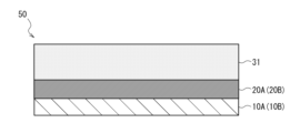
- Method 1 First, as shown in FIG. 2, a laminate in which a metal layer 10A and an adhesive layer 20A are laminated, and a laminate in which a metal layer 10B and an adhesive layer 20B are laminated are respectively prepared. These will be referred to as a first laminate 40.
- a dispersion composition that will become the inorganic filler-containing fluororesin layer 30 is applied to the adhesive layer 20A and the adhesive layer 20B of the first laminate 40 to a predetermined thickness, and after drying, the fluororesin is melted.
- a dispersed composition layer 31 is formed as shown in FIG. 3, and two second laminates 50 are produced.
- the dispersed composition layer 31 of the second laminate 50 includes voids.
- the two second laminates 50 are bonded together by thermocompression so that the dispersed composition layers 31 face each other.
- the fluororesin layer 31 is cooled and solidified to eliminate voids and form the fluororesin layer 30 containing an inorganic filler.
- the thermocompression bonding temperature may be at least the melting point Tm2 of the inorganic filler-containing fluororesin layer 30, and the upper limit can be set as appropriate depending on the resin type, but for example, within the range of 10 to 80 °C below the melting point Tm2.
- the temperature is high.
- the pressure during thermocompression bonding can be determined as appropriate depending on the type of resin, but is preferably within the range of 2 to 12 MPa, for example.
- metal layer 10A/adhesive layer 20A/inorganic filler-containing fluororesin layer 30 (however, a layer in which two dispersed composition layers 31 are bonded together)/adhesive layer 20B/ A metal-clad laminate 100 having a layered structure in which the metal layers 10B are laminated in this order can be manufactured.
- Method 2 First, a laminate in which the metal layer 10A and the adhesive layer 20A are laminated, and a laminate in which the metal layer 10B and the adhesive layer 20B are laminated are respectively prepared, and these are referred to as the first laminate 40 (FIG. 2 ).
- a dispersion composition that will become the inorganic filler-containing fluororesin layer 30 is applied to a predetermined thickness on the adhesive layer 20A of the first laminate, and after drying, the fluororesin is heated to a temperature higher than its melting temperature and dispersed.
- a composition layer 31 is formed to form a second laminate 50 (see FIG. 3).
- the thickness of the dispersed composition layer 31 is made approximately twice as thick as in method 1.
- the dispersed composition layer 31 of the second laminate 50 includes voids.
- the second laminate 50 and the first laminate are placed so that the dispersed composition layer 31 of the second laminate 50 and the adhesive layer 20B of the first laminate 40 face each other.
- the laminate 40 is bonded by thermocompression. After the fluororesin in the dispersion composition layer 31 is melted by thermocompression bonding, the fluororesin in the dispersed composition layer 31 is cooled and solidified to eliminate voids and become the inorganic filler-containing fluororesin layer 30.
- the conditions for thermocompression bonding can be the same as in Method 1.
- metal-clad laminate 100 having a layer structure in which metal layer 10A/adhesive layer 20A/inorganic filler-containing fluororesin layer 30/adhesive layer 20B/metal layer 10B are laminated in this order can be manufactured. .
- the dispersion composition used in Methods 1 and 2 preferably contains a fluororesin powder and an inorganic filler, and further contains a dispersant, an organic solvent, etc., if necessary.
- the weight proportion of the fluororesin powder in the dispersion composition is determined based on 100 parts by weight of the total solid content in the dispersion composition, from the viewpoint of lowering the dielectric loss tangent when formed into a film and making it compatible with high-frequency signal transmission. It is preferably within the range of 15 to 40 parts by weight, and more preferably within the range of 20 to 35 parts by weight.
- the weight ratio of the inorganic filler in the dispersion composition is determined from the viewpoint of lowering the coefficient of thermal expansion (CTE) when formed into a film and ensuring dimensional stability when applied to a circuit board. It is preferably within the range of 55 to 75 parts by weight, and more preferably within the range of 60 to 70 parts by weight, based on 100 parts by weight of solid content. Furthermore, when a dispersant is included, the content is preferably 10 parts by weight or less, for example, 0.5 to 5 parts by weight, as an active ingredient of the dispersant, based on 100 parts by weight of the total solid content of the dispersion composition. It is more preferable to set it within the range of 1.
- the total amount of fluororesin powder and inorganic filler should be within the range of 50 to 80% by weight of the entire composition. It is preferable that the content be within the range of 60 to 70% by weight, and more preferably within the range of 60 to 70% by weight.
- the solid content in the dispersion composition means the total of the components excluding the solvent.
- the viscosity of the dispersion composition is not particularly limited, but for example, when the purpose is to coat a thick film of 30 ⁇ m or more, it is preferably within the range of 500 to 50,000 cP, and more preferably within the range of 500 to 30,000 cP.
- the viscosity of the dispersion composition can be measured at a temperature of 25° C. using an E-type viscometer.
- the first laminate 40 used in Methods 1 and 2 can be manufactured, for example, by applying and drying a solution of the adhesive composition onto the metal foil that will become the metal layers 10A and 10B.
- the method of applying the solution of the dispersion composition or adhesive composition onto the metal foil or the adhesive layers 20A, 20B is not particularly limited, and for example, it may be applied using a comma, die, knife, lip, etc. coater. Is possible.
- the metal-clad laminate 100 of the present embodiment obtained as described above can be used as a single-sided circuit board or a double-sided circuit board by processing the wiring circuit by etching the metal layer 10A and/or the metal layer 10B. Circuit boards can be manufactured.
- the metal-clad laminate 100 of this embodiment is mainly useful as a material for circuit boards such as FPCs, rigid-flex circuit boards, and rigid boards.
- circuit boards such as FPCs, rigid-flex circuit boards, and rigid boards.
- one or both of the two metal layers 10A and 10B of the metal-clad laminate 100 shown in FIG. 1 is processed into a pattern by a conventional method to form a wiring layer. It is possible to manufacture circuit boards such as certain FPCs.
- a circuit was processed on only one copper foil side of the double-sided copper-clad laminate to a width of 1 mm in the resin coating direction at 10 mm intervals, and the circuit was cut into 8 cm width x 4 cm length to prepare a measurement sample. Peel strength was measured using a Tensilon tester (manufactured by Toyo Seiki Seisakusho Co., Ltd., product name: Strograph VE-1D). The copper foil was peeled off in a 180° direction at a rate of 50 mm/min, and the median strength was determined when 10 mm was peeled off.
- the ratio of the voids to the entire image was calculated, and the average value of the ratios of the voids in the five images was taken as the porosity.
- the porosity calculated from the image is an area ratio, it was treated as equivalent to a volume ratio by calculating the average value of a plurality of images.
- CTE coefficient of thermal expansion
- the dielectric loss tangent (Df) of the film at 60 GHz was measured using a network analyzer (manufactured by Keysight Technologies, trade name: PNA N5227B) and a split cylinder resonator (SCR resonator). Note that Df during humidity control was measured after the film used for measurement was left for 24 hours under conditions of temperature: 22 to 24° C. and humidity: 45 to 55%.
- the surface roughness of the copper foil was measured using AFM (manufactured by Bruker AXS, trade name: Dimension Icon type SPM), probe (manufactured by Bruker AXS, trade name: TESPA (NCHV), tip radius of curvature 10 nm, Using a spring constant of 42 N/m), measurement was performed in a tapping mode in an area of 80 ⁇ m x 80 ⁇ m on the surface of the copper foil, and the ten-point average roughness (Rzjis) was determined.
- AFM manufactured by Bruker AXS, trade name: Dimension Icon type SPM
- probe manufactured by Bruker AXS, trade name: TESPA (NCHV)
- tip radius of curvature 10 nm Using a spring constant of 42 N/m), measurement was performed in a tapping mode in an area of 80 ⁇ m x 80 ⁇ m on the surface of the copper foil, and the ten-point average roughness (Rzjis) was determined.
- Fluorine resin powder (1) Fluon+ (Fluon is a registered trademark) EA-2000PW 10, AGC fluorine resin powder, tetrafluoroethylene-perfluoroalkyl vinyl ether copolymer, average particle size: 2 to 3 ⁇ m
- Dispersion Composition 1-1 was judged to be a "solid" because it had no fluidity and its viscosity could not be measured.
- dispersion composition 1-1 was diluted and stirred in stages with DMAc so that the total proportion of fluororesin powder (1) and silica filler (1) was 70% by weight based on the total amount, and the mixture was stirred at 100 rpm.
- a dispersion composition 1-2 having a viscosity of 1080 cP as measured was obtained.
- Dispersant composition preparation example 2 In a 310 ml polypropylene container, 100.0 g of fluororesin dispersion (1) (FEP 25.0 g), 59.7 g of silica filler (1), and 6.0 g of dispersant (1) (dispersant active ingredient 3) .0g) were added. Next, the two samples were set in a rotation-revolution stirrer [SK-350G manufactured by Photo Kagaku Co., Ltd.] and stirred for 4 minutes at a revolution speed of 1060 rpm and an autorotation speed of 1060 rpm. I got it.
- SK-350G manufactured by Photo Kagaku Co., Ltd.
- Dispersion Composition 3-1 was judged to be a "solid" because it had no fluidity and its viscosity could not be measured.
- dispersion composition 3-1 was diluted stepwise with DMAc and stirred so that the total proportion of fluororesin powder (1) and silica filler (1) was 65% by weight based on the total amount, and the mixture was stirred at 100 rpm.
- a dispersion composition 3-2 having a viscosity of 1480 cP was obtained when measured.
- Dispersant composition preparation example 4 Two samples were prepared by adding 100.0 g of fluororesin powder (1), 10.0 g of dispersant (1) (5.0 g of dispersant active ingredient), and 90 g of DMAc in a 310 ml polypropylene container. Next, the two samples were set in a rotation-revolution stirrer [SK-350G manufactured by Photo Kagaku Co., Ltd.] and stirred for 4 minutes under the conditions of revolution of 1060 rpm and rotation of 1060 rpm.Dispersion Composition 4 with a viscosity of 130 cP when measured at 100 rpm I got it.
- SK-350G manufactured by Photo Kagaku Co., Ltd.
- the copper foil of the double-sided copper-clad laminate 1 was removed by etching using a ferric chloride aqueous solution to prepare a fluororesin film 1.
- the CTE of the fluororesin film 1 was 23 ppm/K, and the melting point (Tm) was 350°C.
- the copper foil of the double-sided copper-clad laminate 2 was removed by etching using a ferric chloride aqueous solution to prepare a fluororesin film 2.
- the CTE of the fluororesin film 2 was 23 ppm/K, and the melting point (Tm) was 303°C.
- the copper foil of the double-sided copper-clad laminate 3 was removed by etching using a ferric chloride aqueous solution to prepare a fluororesin film 3.
- the CTE of the fluororesin film 3 was 52 ppm/K, and the melting point (Tm) was 325°C.
- the copper foil of the double-sided copper-clad laminate 4 was removed by etching using a ferric chloride aqueous solution to prepare a fluororesin film 4.
- the CTE of the fluororesin film 4 was 240 ppm/K, and the melting point (Tm) was 305°C.
- the copper foil of the double-sided copper-clad laminate 5 was removed by etching using a ferric chloride aqueous solution to prepare a fluororesin film 5.
- the CTE of the fluororesin film 5 was 180 ppm/K, and the melting point (Tm) was 260°C.
- Polyamic acid solution A was evenly applied onto a copper foil (electrolytic copper foil, thickness: 12 ⁇ m, ten-point average roughness Rzjis on the resin layer side: 0.6 ⁇ m) so that the thickness after curing was approximately 25 ⁇ m. After that, heat drying was performed at 120° C. for 2 minutes to remove the solvent. Furthermore, stepwise heat treatment was performed from 120° C. to 360° C. for 10 minutes to complete imidization and obtain a single-sided copper-clad laminate 6.
- Polyimide film A had a CTE of 51 ppm/K, a glass transition temperature of 227°C, a storage modulus of 2.7 x 10 7 Pa at 300°C, and a storage modulus of 1.1 x 10 7 Pa at 350°C. This confirmed that it was a thermoplastic polyimide and had a storage modulus of 1 ⁇ 10 6 Pa or more at 325°C.
- Polyamic acid solution B was evenly applied onto a copper foil (electrolytic copper foil, thickness: 12 ⁇ m, ten-point average roughness Rzjis on the resin layer side: 0.6 ⁇ m) so that the thickness after curing was approximately 25 ⁇ m. After that, heat drying was performed at 120° C. for 2 minutes to remove the solvent. Furthermore, stepwise heat treatment was performed from 120° C. to 360° C. for 10 minutes to complete imidization and obtain a single-sided copper-clad laminate 7.
- a copper foil electrolytic copper foil, thickness: 12 ⁇ m, ten-point average roughness Rzjis on the resin layer side: 0.6 ⁇ m
- Polyimide film B has a CTE of 55 ppm/K, a glass transition temperature of 332°C, a storage modulus of 1.0 x 10 9 Pa at 300°C, and a storage modulus of 5.6 x 10 7 Pa at 350°C. It was a thermoplastic polyimide.
- Example 1> After applying polyamic acid solution A as an adhesive layer on a copper foil (electrolytic copper foil, thickness: 12 ⁇ m, ten-point average roughness Rzjis on the resin layer side: 0.6 ⁇ m), it was heated at 120°C for 1 minute. The solvent was removed by heating and drying. Furthermore, stepwise heat treatment was performed from 120° C. to 360° C. for 5 minutes to complete imidization.
- a copper foil electrolytic copper foil, thickness: 12 ⁇ m, ten-point average roughness Rzjis on the resin layer side: 0.6 ⁇ m
- drying treatment was performed at 80° C. for 1 minute and at 120° C. for 3 minutes using a hot air oven.
- heat treatment was performed at 280° C. for 3 minutes and at 340° C. for 6 minutes to obtain a single-sided copper-clad laminate 8.
- ⁇ Peel strength 0.7 kN/m or more was rated as ⁇ (good), and less than 0.7 kN/m was rated as ⁇ (unsatisfactory).
- ⁇ Resin flow A case where the maximum amount of resin flowing out from the edge of the double-sided copper-clad laminate was less than 1 mm was rated as ⁇ (good), and a case where the maximum amount of resin flowing out from the edge of the double-sided copper-clad laminate was 1 mm or more was rated as ⁇ (unsatisfactory).
- ⁇ Void A cross-sectional observation using SEM revealed that the void was 5 vol. % is ⁇ (good), and the void is 5 vol.
- ⁇ CTE 30 ppm/K or less was rated ⁇ (excellent), more than 30 ppm/K and less than 60 ppm/K was rated ⁇ (good), and more than 60 ppm/K was rated ⁇ (unsatisfactory).
- ⁇ Dielectric loss tangent Those less than 0.0020 were rated ⁇ (excellent), those greater than 0.0020 and less than 0.0025 were rated ⁇ (good), and those greater than 0.0025 were rated ⁇ (unsatisfactory).
- Example 2 A single-sided copper-clad laminate 9 was produced in the same manner as in Example 1, except that polyamic acid solution B was applied as an adhesive layer, and then a double-sided copper-clad laminate 7 was produced by pressing. A fluororesin film 7 was obtained by removing the copper foil of the plate 7. The obtained double-sided copper-clad laminate 7 and fluororesin film 7 were evaluated. The evaluation results are shown in Table 1. Note that the evaluation results were determined in the same manner as in Example 1.
- Example 3 After producing a single-sided copper-clad laminate 10 in the same manner as in Example 2 except for changing the thickness of the adhesive layer and the inorganic filler-containing fluororesin layer, pressing was performed to produce a double-sided copper-clad laminate 8, A fluororesin film 8 was obtained by removing the copper foil from the double-sided copper-clad laminate 8. The obtained double-sided copper-clad laminate 8 and fluororesin film 8 were evaluated. The evaluation results are shown in Table 1. Note that the evaluation results were determined in the same manner as in Example 1.
- Example 4> After applying the dispersion composition 4 as an adhesive layer on a copper foil (electrolytic copper foil, thickness: 12 ⁇ m, ten-point average roughness Rzjis on the resin layer side: 0.6 ⁇ m), at 80° C. for 1 minute, The solvent was removed by heating and drying at 120° C. for 3 minutes. Furthermore, heat treatment was performed at 280°C for 1.5 minutes and at 340°C for 3 minutes.
- a copper foil electrolytic copper foil, thickness: 12 ⁇ m, ten-point average roughness Rzjis on the resin layer side: 0.6 ⁇ m
- Dispersion Composition 2 After coating Dispersion Composition 2 on the adhesive layer as an inorganic filler-containing fluororesin layer, drying treatment was performed at 80° C. for 1 minute and at 120° C. for 3 minutes using a hot air oven. Next, heat treatment was performed at 240° C. for 3 minutes and at 300° C. for 6 minutes to obtain a single-sided copper-clad laminate 11.
- Example 5> After producing the single-sided copper-clad laminate 12 in the same manner as in Example 1, except that the dispersion composition 3-2 was applied as the inorganic filler-containing fluororesin layer and the pressing temperature was 335° C., pressing was performed. A double-sided copper-clad laminate 10 was prepared, and the copper foil of the double-sided copper-clad laminate 10 was removed to obtain a fluororesin film 10. The obtained double-sided copper-clad laminate 10 and fluororesin film 10 were evaluated. The evaluation results are shown in Table 1. Note that the evaluation results were determined in the same manner as in Example 1.
- drying treatment was performed at 80° C. for 1 minute and at 120° C. for 3 minutes using a hot air oven.
- heat treatment was performed at 280° C. for 3 minutes and at 340° C. for 6 minutes to obtain a single-sided copper-clad laminate 13.
- Dispersion Composition 2 After coating Dispersion Composition 2 on the adhesive layer as an inorganic filler-containing fluororesin layer, drying treatment was performed at 80° C. for 1 minute and at 120° C. for 3 minutes using a hot air oven. Next, heat treatment was performed at 240° C. for 3 minutes and at 300° C. for 6 minutes to obtain a single-sided copper-clad laminate 15.
- 10A, 10B ...metal layer, 20A, 20B...adhesive layer, 30...inorganic filler-containing fluororesin layer, 31...dispersed composition layer, 40...first laminate, 50...second laminate, 100...metal tension laminate
Landscapes
- Engineering & Computer Science (AREA)
- Microelectronics & Electronic Packaging (AREA)
- Laminated Bodies (AREA)
Priority Applications (1)
| Application Number | Priority Date | Filing Date | Title |
|---|---|---|---|
| JP2024511860A JPWO2023189794A1 (https=) | 2022-03-31 | 2023-03-20 |
Applications Claiming Priority (2)
| Application Number | Priority Date | Filing Date | Title |
|---|---|---|---|
| JP2022-060071 | 2022-03-31 | ||
| JP2022060071 | 2022-03-31 |
Publications (1)
| Publication Number | Publication Date |
|---|---|
| WO2023189794A1 true WO2023189794A1 (ja) | 2023-10-05 |
Family
ID=88201054
Family Applications (1)
| Application Number | Title | Priority Date | Filing Date |
|---|---|---|---|
| PCT/JP2023/010803 Ceased WO2023189794A1 (ja) | 2022-03-31 | 2023-03-20 | 金属張積層板及びその製造方法 |
Country Status (3)
| Country | Link |
|---|---|
| JP (1) | JPWO2023189794A1 (https=) |
| TW (1) | TW202404808A (https=) |
| WO (1) | WO2023189794A1 (https=) |
Cited By (3)
| Publication number | Priority date | Publication date | Assignee | Title |
|---|---|---|---|---|
| WO2025120893A1 (ja) * | 2023-12-07 | 2025-06-12 | 富士高分子工業株式会社 | フッ素樹脂シート、その製造方法及びこれを含む金属張フッ素樹脂基板 |
| WO2025134699A1 (ja) * | 2023-12-22 | 2025-06-26 | 株式会社村田製作所 | 積層基板 |
| KR20260002216A (ko) | 2024-06-28 | 2026-01-06 | 닛테츠 케미컬 앤드 머티리얼 가부시키가이샤 | 수지 필름, 다층 필름, 금속장 적층판 및 그 제조 방법, 수지 조성물, 회로 기판, 전자 디바이스 그리고 전자 기기 |
Citations (3)
| Publication number | Priority date | Publication date | Assignee | Title |
|---|---|---|---|---|
| JP2011137126A (ja) * | 2009-12-02 | 2011-07-14 | Toagosei Co Ltd | 接着剤組成物並びにこれを用いたカバーレイフィルム及びフレキシブル銅張積層板 |
| JP2017024265A (ja) * | 2015-07-22 | 2017-02-02 | 株式会社カネカ | 絶縁性フィルム、絶縁性フィルムの製造方法、および金属張積層板の製造方法 |
| JP2021070160A (ja) * | 2019-10-29 | 2021-05-06 | 昭和電工マテリアルズ株式会社 | フッ素樹脂基板積層体 |
-
2023
- 2023-03-20 WO PCT/JP2023/010803 patent/WO2023189794A1/ja not_active Ceased
- 2023-03-20 JP JP2024511860A patent/JPWO2023189794A1/ja active Pending
- 2023-03-25 TW TW112111327A patent/TW202404808A/zh unknown
Patent Citations (3)
| Publication number | Priority date | Publication date | Assignee | Title |
|---|---|---|---|---|
| JP2011137126A (ja) * | 2009-12-02 | 2011-07-14 | Toagosei Co Ltd | 接着剤組成物並びにこれを用いたカバーレイフィルム及びフレキシブル銅張積層板 |
| JP2017024265A (ja) * | 2015-07-22 | 2017-02-02 | 株式会社カネカ | 絶縁性フィルム、絶縁性フィルムの製造方法、および金属張積層板の製造方法 |
| JP2021070160A (ja) * | 2019-10-29 | 2021-05-06 | 昭和電工マテリアルズ株式会社 | フッ素樹脂基板積層体 |
Cited By (4)
| Publication number | Priority date | Publication date | Assignee | Title |
|---|---|---|---|---|
| WO2025120893A1 (ja) * | 2023-12-07 | 2025-06-12 | 富士高分子工業株式会社 | フッ素樹脂シート、その製造方法及びこれを含む金属張フッ素樹脂基板 |
| JP7713117B1 (ja) * | 2023-12-07 | 2025-07-24 | 富士高分子工業株式会社 | フッ素樹脂シート、その製造方法及びこれを含む金属張フッ素樹脂基板 |
| WO2025134699A1 (ja) * | 2023-12-22 | 2025-06-26 | 株式会社村田製作所 | 積層基板 |
| KR20260002216A (ko) | 2024-06-28 | 2026-01-06 | 닛테츠 케미컬 앤드 머티리얼 가부시키가이샤 | 수지 필름, 다층 필름, 금속장 적층판 및 그 제조 방법, 수지 조성물, 회로 기판, 전자 디바이스 그리고 전자 기기 |
Also Published As
| Publication number | Publication date |
|---|---|
| JPWO2023189794A1 (https=) | 2023-10-05 |
| TW202404808A (zh) | 2024-02-01 |
Similar Documents
| Publication | Publication Date | Title |
|---|---|---|
| WO2023189794A1 (ja) | 金属張積層板及びその製造方法 | |
| US10377110B2 (en) | Copper clad laminate | |
| JP7559767B2 (ja) | 非水系分散液、積層体の製造方法及び成形物 | |
| CN113227232B (zh) | 粉末分散液、层叠体和印刷基板 | |
| JP7283208B2 (ja) | パウダー分散液、積層体の製造方法、積層体及びプリント基板の製造方法 | |
| JP7093608B2 (ja) | フッ素系樹脂含有ポリイミド前駆体溶液組成物、それを用いたポリイミド、ポリイミドフィルム、およびそれらの製造方法 | |
| JP6491947B2 (ja) | フッ素系樹脂含有ポリイミド前駆体溶液組成物、それを用いたポリイミド、ポリイミドフィルム、およびそれらの製造方法 | |
| JP7141446B2 (ja) | 多層フィルム及び金属積層板 | |
| WO2020158604A1 (ja) | 積層体及びその製造方法、複合積層体の製造方法、並びにポリマーフィルムの製造方法 | |
| JP7371681B2 (ja) | 液状組成物、パウダー、及び、パウダーの製造方法 | |
| JP7635715B2 (ja) | 非水系分散液及び積層体の製造方法 | |
| KR20030071840A (ko) | 폴리아릴케톤수지 필름과 그 금속적층체 | |
| JP2021075030A (ja) | 積層体、積層体の製造方法、シート、及びプリント回路基板 | |
| JP2024109088A (ja) | フッ素樹脂シート、銅張積層体、回路用基板及びアンテナ | |
| JP7441029B2 (ja) | 樹脂フィルム及び金属張積層板 | |
| JP7722194B2 (ja) | 積層体の製造方法及び液状組成物 | |
| JP7740231B2 (ja) | 多層フィルム、その製造方法、金属張積層体及びプリント配線基板の製造方法 | |
| JP2025049784A (ja) | 金属張積層板及びその製造方法 | |
| JP7468520B2 (ja) | 液状組成物 | |
| WO2023189795A1 (ja) | 分散組成物、フッ素系樹脂フィルム、金属張積層板及びその製造方法 | |
| JP7762314B2 (ja) | 分散組成物、フッ素系樹脂フィルム、金属張積層板及びその製造方法 | |
| WO2023080113A1 (ja) | 誘電体シート、高周波プリント配線板用基板及び高周波プリント配線板 | |
| JP2024142753A (ja) | 両面金属張積層板の製造方法 | |
| CN100415831C (zh) | 薄膜及其金属积层体 | |
| JP7713117B1 (ja) | フッ素樹脂シート、その製造方法及びこれを含む金属張フッ素樹脂基板 |
Legal Events
| Date | Code | Title | Description |
|---|---|---|---|
| 121 | Ep: the epo has been informed by wipo that ep was designated in this application |
Ref document number: 23779810 Country of ref document: EP Kind code of ref document: A1 |
|
| ENP | Entry into the national phase |
Ref document number: 2024511860 Country of ref document: JP Kind code of ref document: A |
|
| NENP | Non-entry into the national phase |
Ref country code: DE |
|
| 122 | Ep: pct application non-entry in european phase |
Ref document number: 23779810 Country of ref document: EP Kind code of ref document: A1 |