WO2023189751A1 - 端子の接続モジュール及び端子 - Google Patents
端子の接続モジュール及び端子 Download PDFInfo
- Publication number
- WO2023189751A1 WO2023189751A1 PCT/JP2023/010666 JP2023010666W WO2023189751A1 WO 2023189751 A1 WO2023189751 A1 WO 2023189751A1 JP 2023010666 W JP2023010666 W JP 2023010666W WO 2023189751 A1 WO2023189751 A1 WO 2023189751A1
- Authority
- WO
- WIPO (PCT)
- Prior art keywords
- terminal
- friction coefficient
- contact surface
- plating layer
- clamping
- Prior art date
- Legal status (The legal status is an assumption and is not a legal conclusion. Google has not performed a legal analysis and makes no representation as to the accuracy of the status listed.)
- Ceased
Links
Images






Classifications
-
- H—ELECTRICITY
- H01—ELECTRIC ELEMENTS
- H01R—ELECTRICALLY-CONDUCTIVE CONNECTIONS; STRUCTURAL ASSOCIATIONS OF A PLURALITY OF MUTUALLY-INSULATED ELECTRICAL CONNECTING ELEMENTS; COUPLING DEVICES; CURRENT COLLECTORS
- H01R13/00—Details of coupling devices of the kinds covered by groups H01R12/70 or H01R24/00 - H01R33/00
- H01R13/02—Contact members
- H01R13/10—Sockets for co-operation with pins or blades
- H01R13/11—Resilient sockets
- H01R13/113—Resilient sockets co-operating with pins or blades having a rectangular transverse section
-
- H—ELECTRICITY
- H01—ELECTRIC ELEMENTS
- H01R—ELECTRICALLY-CONDUCTIVE CONNECTIONS; STRUCTURAL ASSOCIATIONS OF A PLURALITY OF MUTUALLY-INSULATED ELECTRICAL CONNECTING ELEMENTS; COUPLING DEVICES; CURRENT COLLECTORS
- H01R4/00—Electrically-conductive connections between two or more conductive members in direct contact, i.e. touching one another; Means for effecting or maintaining such contact; Electrically-conductive connections having two or more spaced connecting locations for conductors and using contact members penetrating insulation
- H01R4/28—Clamped connections, spring connections
- H01R4/48—Clamped connections, spring connections utilising a spring, clip, or other resilient member
-
- H—ELECTRICITY
- H01—ELECTRIC ELEMENTS
- H01R—ELECTRICALLY-CONDUCTIVE CONNECTIONS; STRUCTURAL ASSOCIATIONS OF A PLURALITY OF MUTUALLY-INSULATED ELECTRICAL CONNECTING ELEMENTS; COUPLING DEVICES; CURRENT COLLECTORS
- H01R13/00—Details of coupling devices of the kinds covered by groups H01R12/70 or H01R24/00 - H01R33/00
- H01R13/02—Contact members
- H01R13/15—Pins, blades or sockets having separate spring member for producing or increasing contact pressure
-
- H—ELECTRICITY
- H01—ELECTRIC ELEMENTS
- H01R—ELECTRICALLY-CONDUCTIVE CONNECTIONS; STRUCTURAL ASSOCIATIONS OF A PLURALITY OF MUTUALLY-INSULATED ELECTRICAL CONNECTING ELEMENTS; COUPLING DEVICES; CURRENT COLLECTORS
- H01R4/00—Electrically-conductive connections between two or more conductive members in direct contact, i.e. touching one another; Means for effecting or maintaining such contact; Electrically-conductive connections having two or more spaced connecting locations for conductors and using contact members penetrating insulation
- H01R4/58—Electrically-conductive connections between two or more conductive members in direct contact, i.e. touching one another; Means for effecting or maintaining such contact; Electrically-conductive connections having two or more spaced connecting locations for conductors and using contact members penetrating insulation characterised by the form or material of the contacting members
-
- H—ELECTRICITY
- H01—ELECTRIC ELEMENTS
- H01R—ELECTRICALLY-CONDUCTIVE CONNECTIONS; STRUCTURAL ASSOCIATIONS OF A PLURALITY OF MUTUALLY-INSULATED ELECTRICAL CONNECTING ELEMENTS; COUPLING DEVICES; CURRENT COLLECTORS
- H01R13/00—Details of coupling devices of the kinds covered by groups H01R12/70 or H01R24/00 - H01R33/00
- H01R13/02—Contact members
- H01R13/03—Contact members characterised by the material, e.g. plating, or coating materials
Definitions
- the present disclosure relates to a terminal connection module and a terminal.
- Patent Document 1 includes a plate-shaped connection terminal, a spring portion, and a housing that has an insertion port into which the mating terminal is inserted and holds the spring portion, and is connected to the mating terminal inserted into the insertion port.
- a connector is disclosed in which a terminal is sandwiched between spring parts.
- an object of the present disclosure is to improve the holding force of the terminals and further enhance the wear resistance between the terminals when the terminals are held between the holding members.
- the terminal connection module of the present disclosure includes a first terminal including a first terminal connection part, a second terminal including a second terminal connection part, and the first terminal connection part and the second terminal connection part stacked together. a clamping member that clamps the first terminal connecting part in a state where the first terminal connecting part contacts the second terminal connecting part; and a clamping member that is located on the opposite side of the first terminal contacting surface.
- the second terminal connecting portion has a second terminal contacting surface that contacts the first terminal connecting portion, and the second terminal contacting portion is located on the opposite side from the second terminal contacting surface, and the second terminal connecting portion has a second terminal contacting surface that contacts the first terminal connecting portion and the clamping member has a first clamping surface that contacts the first clamping surface, and a second clamping surface that contacts the second clamping surface, the clamping member has a second clamping surface that contacts the first clamping surface;
- the maximum friction coefficient between the terminal contact surface and the second terminal contact surface is the maximum friction coefficient between the first receiving surface and the first clamping surface, and the maximum friction coefficient between the second receiving surface and the second clamping surface.
- the terminal of the present disclosure includes a terminal connection portion, and the terminal connection portion is located on a side opposite to the terminal contact surface that contacts the mating terminal, and the terminal contact surface is connected to the mating terminal.
- the terminal includes a receiving surface that receives a pressing force, and the terminal contact surface and the receiving surface have plating layers of different materials.
- the present disclosure when the terminals are held between the holding members, it is possible to improve the holding force of the terminals and further enhance the wear resistance between the terminals.
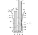
- FIG. 1 is an exploded perspective view showing a terminal connection module according to an embodiment.
- FIG. 2 is a sectional view showing a terminal connection module.
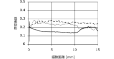
- FIG. 3 is a diagram showing the change in friction coefficient with respect to the sliding distance in Experimental Example 1.
- FIG. 4 is a diagram showing the change in the friction coefficient with respect to the sliding distance in Experimental Example 2.
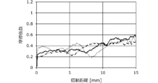
- FIG. 5 is a diagram showing changes in the friction coefficient with respect to the sliding distance in Experimental Example 3.
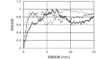
- FIG. 6 is a diagram showing changes in the friction coefficient with respect to the sliding distance in Experimental Example 4.
- FIG. 7 is a diagram showing changes in friction coefficient with respect to sliding distance in Experimental Example 5.
- FIG. 8 is a diagram showing changes in the friction coefficient with respect to the sliding distance in Experimental Example 6.
- FIG. 9 is a diagram showing changes in the friction coefficient with respect to the sliding distance in Experimental Example 7.
- FIG. 10 is a diagram showing the relationship between the purity of the silver plating layer and the maximum coefficient of friction.
- FIG. 11 is a diagram showing the presence or absence of plating cracks for Experimental Examples 10, 11, and 12.
- FIG. 12 is a diagram showing the state of cracks that occurred in the silver plating layer in Experimental Example 10.
- FIG. 13 is a diagram showing the change in the friction coefficient with respect to the sliding distance in Experimental Example 13.
- FIG. 14 is a diagram showing the change in the friction coefficient with respect to the sliding distance in Experimental Example 14.
- the terminal connection module of the present disclosure is as follows.
- a clamping member that clamps a first terminal including a first terminal connecting portion, a second terminal including a second terminal connecting portion, and the first terminal connecting portion and the second terminal connecting portion in an overlapping state. and a first terminal contact surface in which the first terminal connection portion contacts the second terminal connection portion, and a first terminal contact surface located on the opposite side of the first terminal contact surface and in contact with the holding member.
- the second terminal contact surface has a second terminal contact surface in contact with the first terminal contact surface; and a second terminal contact surface located on the opposite side of the second terminal contact surface and in contact with the holding member.
- the holding member has a first holding surface in contact with the first receiving surface, and a second holding surface in contact with the second receiving surface, and the holding member has a first holding surface in contact with the first receiving surface, and a second holding surface in contact with the second receiving surface, and
- the maximum friction coefficient between the two terminal contact surfaces is the maximum friction coefficient between the first receiving surface and the first clamping surface, and the maximum friction between the second receiving surface and the second clamping surface.
- the terminal connection module has at least one of the coefficients less than the maximum friction coefficient.
- this terminal connection module since the maximum coefficient of friction between the first terminal contact surface and the second terminal contact surface is relatively small, slight sliding due to insertion/removal of the first terminal or second terminal, cooling/heating cycle, etc. The resulting wear is less likely to occur on the first terminal contact surface and the second terminal contact surface. Thereby, wear resistance can be improved between the first terminal contact surface and the second terminal contact surface.
- at least one of the maximum friction coefficient between the first receiving surface and the first clamping surface and the maximum friction coefficient between the second clamping surface and the second clamping surface is relatively large. , the holding force of at least one of the first terminal and the second terminal can be increased.
- the holding force of at least one of the first terminal and the second terminal is improved, and the holding force between the first terminal and the second terminal is improved. It is possible to further improve the wear resistance between the parts.
- the maximum friction coefficient between the first terminal contact surface and the second terminal contact surface is the maximum friction coefficient between the first receiving surface and the first clamping surface.
- the maximum friction coefficient between the second receiving surface and the second clamping surface may be smaller than both of the maximum friction coefficient between the second receiving surface and the second holding surface.
- At least one surface of the first receiving surface and the second receiving surface has a high friction coefficient plating layer, and the high friction coefficient
- the plating layer may be a plating layer that increases the maximum coefficient of friction with respect to the first clamping surface or the second clamping surface compared to a case without the high friction coefficient plating layer.
- the high friction coefficient plating layer can increase the maximum friction coefficient at least between the first receiving surface and the first clamping surface and between the second receiving surface and the second clamping surface. can.
- the clamping member is a clip made of stainless steel, and at least one of the first clamping surface and the second clamping surface has the stainless steel exposed.
- the high friction coefficient plating layer is a tin plating layer, and between the first receiving surface and the first clamping surface and between the second receiving surface and the second clamping surface. At least one of the stainless steel and the tin plating layer may be in direct contact with each other.
- the stainless steel and the tin plating layer are in direct contact with each other, there is a gap between the first receiving surface and the first clamping surface and between the second receiving surface and the second clamping surface. In at least one of the above, the maximum coefficient of friction can be increased.
- a terminal connection module according to any one of (1) to (4), wherein each of the first terminal contact surface and the second terminal contact surface has a low friction coefficient plating layer,
- the low friction coefficient plating layer is a plating layer that reduces the maximum friction coefficient between the first terminal contact surface and the second terminal contact surface compared to a case where the low friction coefficient plating layer does not exist, and the first The low friction coefficient plating layers may be in direct contact with each other between the terminal contact surface and the second terminal contact surface.
- the low friction coefficient plating layers are in direct contact with each other between the first terminal contact surface and the second terminal contact surface.
- the maximum coefficient of friction can be reduced.
- the low friction coefficient plating layer may be a silver plating layer with a purity of 95.0 mass percent or more and less than 99.0 mass percent.
- the silver plating layers with a purity of 95.0 mass percent or more and less than 99.0 mass percent are in direct contact with each other between the first terminal contact surface and the second terminal contact surface.
- the maximum coefficient of friction between the first terminal contact surface and the second terminal contact surface can be reduced while suppressing cracks.
- oil may be present between the first terminal contact surface and the second terminal contact surface.
- the oil can reduce the maximum coefficient of friction between the first terminal contact surface and the second terminal contact surface.
- terminals of the present disclosure are as follows.
- a terminal connecting portion is provided, the terminal connecting portion is located on the opposite side of the terminal contact surface that contacts the mating terminal, and the terminal contact surface is pressed against the mating terminal.
- the terminal includes a receiving surface for receiving the terminal, and the terminal contact surface and the receiving surface have plating layers of different materials.
- the terminal contact surface and the receiving surface have plating layers made of different materials, so that the maximum coefficient of friction between the terminal contact surface and the mating terminal is reduced between the receiving surface and the member that presses the receiving surface. It is easy to make the maximum coefficient of friction smaller than the maximum coefficient of friction.
- the maximum friction coefficient between the terminal contact surface and the other terminal is made smaller than the maximum friction coefficient between the receiving surface and the member that presses the receiving surface. easy.
- FIG. 1 is an exploded perspective view showing a terminal connection module 10.
- FIG. 2 is a sectional view showing the terminal connection module 10. As shown in FIG.
- the terminal connection module 10 includes a first terminal 20, a second terminal 30, and a clamping member 40.
- the terminal connection module 10 is used, for example, as a component that electrically connects electrical components in a vehicle.
- the first terminal 20 includes a first terminal connecting portion 24 .
- the first terminal 20 is formed, for example, by pressing a metal plate.
- the first terminal 20 is assumed to be a terminal connected to the end of the electric wire 18.
- the electric wire 18 is, for example, a covered electric wire that includes a core wire 18a and a covering 18b that covers the core wire 18a.
- a core wire 18a is exposed at the end of the electric wire 18.
- the first terminal 20 includes a wire connecting portion 22 that is connected to a first terminal connecting portion 24 .
- the wire connection portion 22 is a portion connected to the core wire 18a exposed at the end of the wire 18.
- the wire connection portion 22 is formed into a plate shape. By welding, soldering, or the like, the core wire 18a at the end of the electric wire 18 to the wire connection portion 22, the core wire 18a is fixed to the wire connection portion 22 and electrically connected.
- the wire connecting portion 22 may have a configuration including a crimping piece that is crimped onto the core wire 18a.
- the first terminal 20 be a terminal connected to the electric wire 18.
- the first terminal 20 may be directly screwed, soldered, etc. to a circuit in an electrical component.
- the first terminal connecting portion 24 is formed into a plate shape. More specifically, the first terminal connection portion 24 is formed into a rectangular plate shape that is long in one direction.
- the first terminal connecting portion 24 has a first terminal contact surface 25 and a first receiving surface 26 .
- One main surface of the first terminal connecting portion 24 is the first terminal contact surface 25 .
- the main surface of the first terminal connecting portion 24 opposite to the first terminal contact surface 25 is the first receiving surface 26 .
- the first terminal contact surface 25 and the first receiving surface 26 are surfaces facing opposite to each other in the thickness direction of the first terminal connecting portion 24.
- the first terminal contact surface 25 is a surface that faces the second terminal connection portion 34 and is in contact with the second terminal connection portion 34 .
- the first receiving surface 26 is a surface that faces the clamping member 40 and receives clamping force from the clamping member 40 .
- the first terminal connection section 24 has a contact section 25P.
- the number of contact portions 25P is not particularly limited, in this embodiment, a plurality of (here, two) contact portions 25P are formed at intervals in the longitudinal direction of the first terminal connection portion 24.
- the contact portion 25P is a portion of the first terminal connecting portion 24 that partially projects toward the first terminal contact surface 25 side. Therefore, from the first terminal contact surface 25 side, the contact portion 25P is observed as a partially protruding portion, and from the first receiving surface 26, the contact portion 25P is observed as a partially recessed portion.
- the most protruding portion of the contact portion 25P may be formed in a planar shape. Thereby, the contact area between the contact portion 25P and the second terminal connection portion 34 can be increased.
- the shape of the contact portion 25P is not particularly limited, it may be formed, for example, in a rectangular shape, an elongated shape, an elliptical shape, or the like.
- the contact portion 25P may have an outer circumferential surface that slopes inward toward the most protruding portion. Thereby, the second terminal connecting portion 34 easily slides on the outer peripheral surface of the contact portion 25P and is guided onto the contact portion 25P.
- the most protruding portion of the contact portion 25P of the first terminal connection portion 24 can be in contact with the second terminal connection portion 34. This makes it possible to destroy the oxide film on the surface of the terminal and improve contact pressure. Note that it is not essential that the contact portion 25P be formed in the first terminal connection portion 24.
- the second terminal 30 includes a second terminal connection part 34.
- the second terminal 30 is formed, for example, by pressing a metal plate.
- the second terminal 30 is, for example, a terminal connected to the end of an electric wire like the first terminal 20.
- the wire connection portion of the second terminal 30 is omitted.
- the second terminal 30 is not necessarily a terminal connected to an electric wire, but may be a terminal connected to a circuit in an electric component.
- the second terminal connection portion 34 is formed into a plate shape. More specifically, the second terminal connecting portion 34 is formed into a rectangular plate shape that is long in one direction.
- the second terminal connecting portion 34 has a second terminal contact surface 35 and a second receiving surface 36 .
- One main surface of the second terminal connecting portion 34 is the second terminal contact surface 35 .
- the main surface of the second terminal connecting portion 34 opposite to the second terminal contact surface 35 is the second receiving surface 36 . That is, the second terminal contact surface 35 and the second receiving surface 36 are surfaces facing opposite to each other in the thickness direction of the second terminal connecting portion 34.
- the second terminal contact surface 35 is a surface that faces the first terminal connection section 24 and is in contact with the first terminal connection section 24 .
- the second receiving surface 36 is a surface that faces the clamping member 40 and receives clamping force from the clamping member 40 .
- the second terminal connecting portion 34 and the second receiving surface 36 on both sides of the second terminal connecting portion 34 are formed flat.
- the second terminal connecting portion 34 may have a contact portion protruding toward the first terminal connecting portion 24 side.
- the holding member 40 is a member that holds the first terminal connecting portion 24 and the second terminal connecting portion 34 in an overlapping state.
- the holding member 40 is formed, for example, by pressing a metal plate.
- the holding member 40 may be a member called a clip.
- the holding member 40 includes a first holding piece 42 , a second holding piece 44 , and a connecting piece 46 .
- the first holding piece 42 is formed into a plate shape, more specifically, a rectangular plate shape that is long in one direction.
- the first clamping piece 42 has a first clamping surface 43 that faces the first receiving surface 26 , and this first clamping surface 43 contacts the first receiving surface 26 .
- the first holding piece 42 has a first pressing portion 42P.
- the first pressing portion 42P is formed by partially protruding the first holding piece 42 inward.
- the first pressing portion 42P protrudes in an elongated dome shape, and its most protruding portion has a gentle spherical shape close to a flat surface.
- the shape of the first pressing portion 42P is arbitrary. It is not essential that the first pressing portion 42P be formed.
- the second holding piece 44 is formed into a plate shape, more specifically, a rectangular plate shape that is long in one direction.
- the second clamping piece 44 has a second clamping surface 45 that faces the second receiving surface 36 , and this second clamping surface 45 contacts the second receiving surface 36 .
- the second holding piece 44 has a second pressing portion 44P.
- the second pressing portion 44P is formed by partially protruding the second holding piece 44 inward.
- the second pressing portion 44P protrudes in an elongated dome shape, and its most protruding portion has a gentle spherical shape close to a flat surface.
- the shape of the second pressing portion 44P is arbitrary. It is not essential that the second pressing portion 44P be formed.
- the tip edges of the first clamping piece 42 and the second clamping piece 44 on the opposite side from the part where the connecting piece 46 is continuous are formed into guide edges 42g and 44g that slope outward in a direction away from each other.
- the first terminal connecting portion 24 and the second terminal connecting portion 34 can be easily guided between the first holding piece 42 and the second holding piece 44 by the guide edges 42g and 44g.
- the connecting piece 46 is a part that continues to the base ends of the first clamping piece 42 and the second clamping piece 44 and connects the first clamping piece 42 and the second clamping piece 44 in a parallel state with an interval between them. That is, the first clamping piece 42, the connecting piece 46, and the second clamping piece 44 are connected in a U-shape.
- the first clamping piece 42 and the second clamping piece 44 change the interval between the first clamping piece 42 and the second clamping piece 44 by utilizing the connecting part to the connecting piece 46 and the elastic deformation of the connecting piece 46. can do.
- the minimum distance between the first clamping piece 42 and the second clamping piece 44 is smaller than the sum of the thickness of the first terminal connecting part 24 and the thickness of the second terminal connecting part 34. Therefore, by elastically deforming the holding member 40 and widening the interval between the first holding piece 42 and the second holding piece 44, a first terminal contact surface is created between the first holding piece 42 and the second holding piece 44. 25 and the second terminal connecting portion 34 can be arranged in a superimposed manner. In this state, the first clamping surface 43 pushes the first receiving surface 26 and the second clamping surface 45 pushes the second receiving surface 36 due to the elastic force that causes the clamping member 40 to return to its original shape.
- first terminal connecting part 24 and the second terminal connecting part 34 are pushed toward each other, and the first terminal contact surface 25 and the second terminal contact surface 35 can contact each other in a pressed state. . Thereby, electrical continuity is obtained between the first terminal 20 and the second terminal 30.
- the holding member 40 has the above configuration. It is not essential that the holding member be electrically conductive; for example, it may be formed of resin or a combination of resin and metal.
- the first terminal 20 and the second terminal 30 are parts through which electricity flows, they may be formed of a material with excellent conductivity.
- the first terminal 20 and the second terminal 30 may be made of copper or a copper alloy.
- the first terminal contact surface 25 and the second terminal contact surface 35 are surfaces that come into contact with each other to obtain electrical continuity. Therefore, in order to suppress oxidation of the first terminal contact surface 25 and the second terminal contact surface 35 and maintain a good electrical connection state between the first terminal contact surface 25 and the second terminal contact surface 35, the first terminal contact surface 25 and the second terminal contact surface 35 are It is envisaged that contact surface 25 and second terminal contact surface 35 have a plating layer. As a plating layer for this purpose, a silver plating layer, a tin plating layer, etc. are assumed.
- the first receiving surface 26 and the second receiving surface 36 are surfaces that receive the force from the holding member 40, and it is not so important to maintain a good electrical connection with the holding member 40. Therefore, regarding the first receiving surface 26 and the second receiving surface 36, the base materials forming the first terminal 20 and the second terminal 30 are exposed as they are, and therefore, the first receiving surface 26 and the second receiving surface 36 are exposed as they are. It is assumed that 36 is a surface where copper or copper alloy is exposed.
- the holding member 40 may be formed of a material with excellent spring properties in order to maintain the first terminal 20 and the second terminal 30 in a sandwiched state.
- the holding member 40 may be formed of stainless steel (including, for example, stainless steel classified as SUS in the JIS standard), particularly stainless steel for springs.
- the contact point between the first terminal contact surface 25 and the second terminal contact surface 35 becomes a contact point between the silver plating layers.
- the contact points between the first receiving surface 26 and the first clamping surface 43 and the contact points between the second receiving surface 36 and the second clamping surface 45 (hereinafter referred to as the contact points between the terminals 20, 30 and the clamping member 40 are referred to as “clamping” points).
- Contact point refers to the contact point between the copper or copper alloy surface and the stainless steel surface.
- the inventor of the present application aims to increase the holding force of the holding member 40 for the first terminal 20 or the second terminal 30, and to improve the wear resistance between the first terminal 20 and the second terminal 30. We have found that it is difficult to balance this with improving sexual performance.
- the maximum friction coefficient at the terminal-to-terminal contact location is larger than the maximum friction coefficient at the clamping contact location.
- the contact points between terminals are required to have wear resistance that can withstand wear caused by insertion and removal of terminals and slight sliding wear caused by cooling and heating cycles.
- wear resistance that can withstand wear caused by insertion and removal of terminals and slight sliding wear caused by cooling and heating cycles.
- wear resistance tends to decrease. For this reason, it is preferable to reduce the maximum coefficient of friction at the contact points between the terminals in order to improve wear resistance.
- the clamping contact portion is required to have a holding performance that can withstand force or vibration in the insertion/extraction direction of the terminals 20, 30 so as not to move.
- the maximum coefficient of friction is small, the terminals 20 and 30 tend to move easily between the clamping members 40, and the holding performance tends to decrease. For this reason, it is preferable to increase the maximum coefficient of friction at the pinching contact location in order to improve the holding performance.
- the inventor of the present application has determined that the maximum friction coefficient ⁇ a between the first terminal contact surface 25 and the second terminal contact surface 35 is the maximum friction coefficient ⁇ b1 between the first receiving surface 26 and the first clamping surface 43. , the maximum friction coefficient ⁇ b2 between the second receiving surface 36 and the second clamping surface 45.
- the maximum friction coefficient ⁇ a is smaller than the maximum friction coefficient ⁇ b1.
- the maximum coefficient of friction between the first member and the second member is, for example, the maximum value of the coefficient of friction measured when the second member is pulled against the first member while applying a constant load. It may be.
- the maximum value may be, for example, the maximum value within a sliding distance range of 15 mm or less.
- the friction coefficient may be measured, for example, by a method based on the Japan Copper Brass Association technical standard (JCBA T311:2002).
- the first terminal contact surface 25 and the second terminal contact surface 35 each have a low friction coefficient plating layer 25F, 35F.
- These low friction coefficient plating layers 25F, 35F are platings that make the maximum friction coefficient ⁇ a between the first terminal contact surface 25 and the second terminal contact surface 35 smaller than when the low friction coefficient plating layers 25F, 35F are not present. It is a layer. It is conceivable that the low friction coefficient plating layers 25F and 35F are in direct contact with each other between the first terminal contact surface 25 and the second terminal contact surface 35.
- a silver plating layer with a purity of 95.0 mass percent or more and less than 99.0 mass percent may be used. This is because a silver plating layer in which the silver purity is less than 95.0 mass percent makes the plating brittle, and plating cracks are likely to occur. In particular, plating cracks are likely to occur when forming the contact portion 25P. This is because when plating cracks occur, the underlying plating or base material may be exposed and the contact resistance at the contact point between the terminals may increase. Further, when the purity of silver exceeds 99.0% by mass, the maximum coefficient of friction ⁇ a tends to increase.
- the silver plating layer with a purity of 95.0 mass percent or more and less than 99.0 mass percent may contain an organic compound, an S (sulfur)-containing material, or an additive element as a content other than silver.
- oil 60 may be interposed between the first terminal contact surface 25 and the second terminal contact surface 35 (see the two-dot chain line in FIG. 2). Due to the lubricity of the oil 60, the maximum friction coefficient ⁇ a at the contact point between the terminals can be reduced.
- At least one surface of the first receiving surface 26 and the second receiving surface 36 is plated with a high friction coefficient.
- a configuration having layers 26F and 36F is conceivable.
- the high friction coefficient plating layers 26F and 36F are plating layers that increase the maximum friction coefficient with respect to the second clamping surface 45 or the second clamping surface 45 compared to the case where there is no high friction coefficient plating layer.
- the clamping member 40 is a clip made of stainless steel, and at least one of the first clamping surface 43 and the second clamping surface 45 is a surface with exposed stainless steel, and has a high coefficient of friction.
- the plating layers 26F and 36F are tin plating layers. The stainless steel and the tin plating layer are in direct contact between at least one or both of the first receiving surface 26 and the first holding surface 43 and between the second receiving surface 36 and the second holding surface 45. It is conceivable that the situation could be set as follows.
- a plating layer that increases the maximum coefficient of friction may be formed on the clamping surfaces 43 and 45 of the clamping member 40.
- a silver plating layer with a purity of 95.0 mass percent or more and less than 99.0 mass percent is adopted, and the silver plating layers of the purity are in contact with each other at the contact point between the terminals.
- a tin plating layer is adopted as the high friction coefficient plating layers 26F and 36F, and the tin plating layer and the stainless steel surface are in contact with each other at the sandwiching contact point, thereby increasing the maximum friction coefficient at the contact point between the terminals.
- ⁇ a can be easily made smaller than the maximum friction coefficients ⁇ b1 and ⁇ b2 at the clamping contact points.
- the terminal connection module 10 configured as described above, since the maximum friction coefficient ⁇ a between the first terminal contact surface 25 and the second terminal contact surface 35 is relatively small, the first terminal 20 or the second terminal Abrasion due to slight sliding due to insertion/removal of the terminal 30, cooling/heating cycles, etc. is unlikely to occur on the first terminal contact surface 25 and the second terminal contact surface 35. Thereby, the wear resistance between the first terminal contact surface 25 and the second terminal contact surface 35 can be improved.
- the maximum friction coefficient ⁇ b1 between the first receiving surface 26 and the first clamping surface 43 and ⁇ b2 between the second receiving surface 36 and the second clamping surface 45 is relatively large, The holding force of at least one of the first terminal 20 and the second terminal 30 by the holding member 40 can be increased. Thereby, the first terminal 20 or the second terminal 30 is difficult to come off from the holding member 40. Further, increasing the maximum friction coefficients ⁇ b1 and ⁇ b2 contributes to making the first terminal 20 and the second terminal 30 difficult to move, and thus also helps to improve wear resistance.
- the holding force of at least one of the first terminal 20 and the second terminal 30 is increased, and the first terminal 20 is The wear resistance between the terminal 30 and the second terminal 30 can be further improved.
- both the maximum friction coefficients ⁇ b1 and ⁇ b2 larger than the maximum friction coefficient ⁇ a, it is difficult for both the first terminal 20 and the second terminal 30 to come off from the holding member 40.
- the maximum friction coefficient ⁇ b1 or the maximum friction coefficient ⁇ b2 can be increased by having the high friction coefficient plating layers 26F, 36F on at least one surface of the first receiving surface 26 and the second receiving surface 36.
- a tin plating layer is adopted as the high friction coefficient plating layers 26F and 36F, and between the first receiving surface 26 and the first clamping surface 43 and between the second receiving surface 36 and the second clamping surface 45.
- the first terminal contact surface 25 and the second terminal contact surface 35 each have a low friction coefficient plating layer 25F, 35F, thereby making it possible to reduce the maximum friction coefficient ⁇ a.
- the maximum friction coefficient ⁇ a can be reduced by interposing the oil 60 between the first terminal contact surface 25 and the second terminal contact surface 35. I can do it.
- the terminal contact surface 25 (or 35) and the receiving surface 26 (or 36) have plating layers of different materials (for example, a combination of a low friction coefficient plating layer 25F and a high friction coefficient plating layer 26F), the terminal contact surface 25 (or 35) and the mating terminal 30 (or 20) can be easily made smaller than the maximum friction coefficient ⁇ b1 (or ⁇ b2) between the receiving surface 26 (or 36) and the holding member 40 that presses the receiving surface.
- the terminal contact surface 25 (or 35) has a silver plating layer with a purity of 95.0 mass percent or more and less than 99.0 mass percent, and the receiving surface 26 (or 36) has a tin plating layer. If it has, it is easy to make the maximum friction coefficient ⁇ a smaller than the maximum friction coefficient ⁇ b1 (or ⁇ b2).
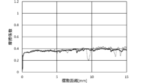
- FIG. 3 shows the change in the friction coefficient with respect to the sliding distance in Experimental Example 1.
- FIG. 4 shows the change in the friction coefficient with respect to the sliding distance in Experimental Example 2. Note that each curve in FIG. 3 shows measurement results for a plurality of samples.
- FIG. 3 shows a legend showing the correspondence of sample numbers (n1, n2, n3) to each curve. Legends are omitted in each figure below.
- the maximum friction coefficient was approximately 0.36, and in the case of FIG. 4, the maximum friction coefficient was approximately 0.29. From FIGS. 3 and 4, it was found that the maximum coefficient of friction between the stainless steel and the copper plate was a relatively small value. Furthermore, from FIGS. 3 and 4, the shape of the copper plate, that is, whether the contact portion 25P is provided as in the first terminal 20 or the contact portion is not provided as in the second terminal 30, the coefficient of friction is greatly affected. I found out that it doesn't give.
- the maximum friction coefficient originally means the maximum value of the friction coefficient between specific objects.
- the maximum value of the multiple measurement results is taken as the maximum friction coefficient.
- FIG. 5 shows the change in the friction coefficient with respect to the sliding distance in Experimental Example 3.
- the maximum coefficient of friction between stainless steel and a copper plate with a tin plating layer is approximately 0.6. Therefore, when a tin plating layer is formed on the first receiving surface 26 and the second receiving surface 36 and stainless steel is exposed on the first holding surface 43 and the second holding surface 45, the maximum friction coefficient ⁇ b1, It is predicted that ⁇ b2 becomes larger and the holding force of the terminals 20 and 30 can be improved. Therefore, it has been found that the tin plating layer can be employed as an example of the high friction coefficient plating layers 26F and 36F.
- Example 4 the coefficient of friction between two copper plates having tin plating layers was measured.
- Experimental Example 5 the coefficient of friction between copper plates having a silver plating layer with a silver purity of 99% by mass or more was measured.
- one copper plate was formed in the same shape as the first terminal 20, and the other copper plate was formed in the same shape as the second terminal 30.
- FIG. 6 shows the change in the friction coefficient with respect to the sliding distance in Experimental Example 4.
- FIG. 7 shows the change in the friction coefficient with respect to the sliding distance in Experimental Example 5.
- the maximum coefficient of friction between the two copper plates with tin plating layers was approximately 0.82.
- the maximum coefficient of friction between the copper plates having silver plating layers with a purity of 99% by mass or more was about 1.00.
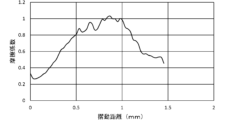
- the maximum friction coefficient between the copper plates having a silver plating layer with a silver purity of 97.6 mass percent was a small value of 0.43.
- FIG. 9 shows the change in the friction coefficient with respect to the sliding distance in Experimental Example 7.
- the maximum friction coefficient between the copper plates having a silver plating layer with a silver purity of 99.6 mass percent was 1.00.
- the maximum coefficient of friction versus purity of silver is shown in FIG. From the figure, it can be seen that the maximum friction coefficient becomes small when the silver purity is less than 99 mass percent, and that the maximum friction coefficient suddenly increases when it exceeds 99 mass percent. Therefore, it has been found that when the purity of silver is less than 99% by mass, the maximum friction coefficient between the copper plates having silver plating layers can be reduced, and it can be used as the low friction coefficient plating layers 25F and 35F.
- the maximum friction coefficient is 0.60
- silver plating with a silver purity of less than 99% is used.
- the maximum coefficient of friction is clearly smaller than 0.60. Therefore, such a combination of plating layers is suitable as an example of making the maximum friction coefficient ⁇ a smaller than at least one of the maximum friction coefficients ⁇ b1 and ⁇ b2, preferably smaller than both.
- Experimental Examples 10, 11, and 12 processing was performed to form a contact portion 25P on a copper plate on which a silver plating layer had already been formed, and it was observed whether or not plating cracking occurred.
- a silver plating layer with a purity of 96.7% by mass was formed
- Experimental Example 11 a silver plating layer with a purity of 97.6% by mass was formed
- Experimental Example 12 a silver plating layer with a purity of 98.5% by mass was formed.
- a layer was formed.
- FIG. 11 shows the presence or absence of plating cracks for each of Experimental Examples 10, 11, and 12.
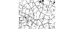
- FIG. 12 shows a microscopic photograph of the surface of the experimental piece in Experimental Example 10 (silver purity 96.7% by mass). As shown in the figure, in the case of Experimental Example 10 (silver purity 96.7% by mass), numerous fine cracks were observed on the surface of the silver plating layer.
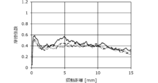
- Example 13 the friction coefficient was measured when oil was interposed between the tin plating layers in Experimental Example 4.
- Experimental Example 14 the friction coefficient when oil was interposed between the silver plating layers in Experimental Example 5 was measured.
- FIG. 13 shows the change in the friction coefficient with respect to the sliding distance in Experimental Example 13.
- FIG. 14 shows the change in the friction coefficient with respect to the sliding distance in Experimental Example 14.
- the maximum friction coefficient was approximately 0.59.
- the maximum friction coefficient was approximately 0.58.
- the maximum friction coefficient ⁇ a when oil is interposed between the first terminal contact surface 25 and the second terminal contact surface 35, the maximum friction coefficient ⁇ a can be made smaller than when no oil is present. Therefore, depending on the values of the maximum friction coefficients ⁇ b1 and ⁇ b2, by interposing oil between the first terminal contact surface 25 and the second terminal contact surface 35, the maximum friction coefficient ⁇ a can be made smaller than the maximum friction coefficients ⁇ b1 and ⁇ b2. can also be made smaller.
- Connection module 18 Wire 18a Core wire 18b Covering 20 First terminal 22 Wire connection portion 24 First terminal connection portion 25 First terminal contact surface 25F Low friction coefficient plating layer 25P Contact portion 26 First receiving surface 26F High friction coefficient plating layer 30 Second terminal 34 Second terminal connecting portion 35 Second terminal contact surface 35F Low friction coefficient plating layer 36 Second receiving surface 36F High friction coefficient plating layer 40 Holding member 42 First holding piece 42P First pressing portion 42g, 44g Guide edge 43 First clamping surface 44 Second clamping piece 44P Second pressing part 45 Second clamping surface 46 Connection piece 60 Oil
Landscapes
- Electroplating Methods And Accessories (AREA)
- Connections Arranged To Contact A Plurality Of Conductors (AREA)
- Coupling Device And Connection With Printed Circuit (AREA)
- Connections By Means Of Piercing Elements, Nuts, Or Screws (AREA)
- Connections Effected By Soldering, Adhesion, Or Permanent Deformation (AREA)
Abstract
Description
最初に本開示の実施態様を列記して説明する。
本開示の端子の接続モジュール及び端子の具体例を、以下に図面を参照しつつ説明する。なお、本開示はこれらの例示に限定されるものではなく、請求の範囲によって示され、請求の範囲と均等の意味および範囲内でのすべての変更が含まれることが意図される。
以下、実施形態に係る端子の接続モジュール及び端子について説明する。図1は端子の接続モジュール10を示す分解斜視図である。図2は端子の接続モジュール10を示す断面図である。
端子の接続モジュール10は、第1端子20と、第2端子30と、挟持部材40とを備える。端子の接続モジュール10は、例えば、車両における電気部品同士を電気的に接続する部品として用いられる。
上記第1端子20及び第2端子30は、電気が流れる部分であるため、導電性に優れた材質で形成されることが考えられる。例えば、第1端子20及び第2端子30は、銅又は銅合金によって形成されていることが考えられる。
以上のように構成された端子の接続モジュール10によると、第1端子接触面25と第2端子接触面35との間の最大摩擦係数μaが比較的小さいため、第1端子20又は第2端子30の挿抜及び冷熱サイクル等による微摺動に起因する摩耗が第1端子接触面25と第2端子接触面35とに生じ難い。これにより、第1端子接触面25と第2端子接触面35との間で耐摩耗性を高めることができる。また、第1受面26と第1挟持面43との間の最大摩擦係数μb1と、第2受面36と第2挟持面45との間のμb2のうちの少なくとも一方が比較的大きいため、挟持部材40による第1端子20及び第2端子30の少なくとも一方の保持力を高めることができる。これにより、第1端子20又は第2端子30が挟持部材40から抜け難い。また、最大摩擦係数μb1、μb2を大きくすることは、第1端子20及び第2端子30を動き難くすることにも貢献するため、耐摩耗性の向上にも役立つ。これにより、第1端子20と第2端子30とを挟持部材40によって挟持した端子の接続モジュール10において、第1端子20及び第2端子30の少なくとも一方の保持力を高めつつ、第1端子20と第2端子30との間での耐摩耗性をより高めることができる。
<挟持接触箇所に関する実験例>
実験例1及び2として、ステンレス鋼と銅板との間の摩擦係数を測定した。実験例1では、銅板を上記第2端子30と同様形状に形成した。実験例2では銅板を第1端子20と同様形状に形成した。実験例1における摺動距離に対する摩擦係数の変化が図3に示される。実験例2における摺動距離に対する摩擦係数の変化が図4に示される。なお、図3における各曲線は、複数のサンプルに対する測定結果を示している。図3に各曲線に対するサンプル番号(n1、n2、n3)の対応付けを示す凡例が示される。以下の各図では凡例は省略される。
実験例4として、スズめっき層を有する2つの銅板間の摩擦係数を測定した。実験例5として銀の純度が99質量パーセント以上の銀めっき層を有する銅板間の摩擦係数を測定した。実験例4及び5において、一方の銅板を第1端子20と同様形状に形成し、他方の銅板を第2端子30と同様形状に形成した。実験例4における摺動距離に対する摩擦係数の変化が図6に示される。実験例5における摺動距離に対する摩擦係数の変化が図7に示される。
18 電線
18a 芯線
18b 被覆
20 第1端子
22 電線接続部
24 第1端子接続部
25 第1端子接触面
25F 低摩擦係数めっき層
25P 接点部
26 第1受面
26F 高摩擦係数めっき層
30 第2端子
34 第2端子接続部
35 第2端子接触面
35F 低摩擦係数めっき層
36 第2受面
36F 高摩擦係数めっき層
40 挟持部材
42 第1挟持片
42P 第1押圧部
42g、44g ガイド縁
43 第1挟持面
44 第2挟持片
44P 第2押圧部
45 第2挟持面
46 連結片
60 オイル
Claims (9)
- 第1端子接続部を含む第1端子と、
第2端子接続部を含む第2端子と、
前記第1端子接続部と前記第2端子接続部とを重ね合せ状態で挟持する挟持部材と、
を備え、
前記第1端子接続部が、前記第2端子接続部に接する第1端子接触面と、前記第1端子接触面とは反対側に位置し前記挟持部材に接触する第1受面とを有し、
前記第2端子接続部が、前記第1端子接続部に接する第2端子接触面と、前記第2端子接触面とは反対側に位置し前記挟持部材に接触する第2受面とを有し、
前記挟持部材が、前記第1受面に接する第1挟持面と、前記第2受面に接する第2挟持面とを有し、
前記第1端子接触面と前記第2端子接触面との間の最大摩擦係数は、前記第1受面と前記第1挟持面との間の最大摩擦係数と、前記第2受面と前記第2挟持面との間の最大摩擦係数のうちの少なくとも一方の最大摩擦係数よりも小さい、端子の接続モジュール。 - 請求項1に記載の端子の接続モジュールであって、
前記第1端子接触面と前記第2端子接触面との間の最大摩擦係数は、前記第1受面と前記第1挟持面との間の最大摩擦係数と、前記第2受面と前記第2挟持面との間の最大摩擦係数との両方の最大摩擦係数よりも小さい、端子の接続モジュール。 - 請求項1又は請求項2に記載の端子の接続モジュールであって、
前記第1受面及び前記第2受面の少なくとも一方の表面が、高摩擦係数めっき層を有し、
前記高摩擦係数めっき層は、当該高摩擦係数めっき層が無い場合よりも前記第1挟持面又は前記第2挟持面に対する最大摩擦係数を大きくするめっき層である、端子の接続モジュール。 - 請求項3に記載の端子の接続モジュールであって、
前記挟持部材はステンレス鋼によって形成されたクリップであり、
前記第1挟持面及び前記第2挟持面の少なくとも一方は前記ステンレス鋼が露出している面であり、
前記高摩擦係数めっき層は、スズめっき層であり、
前記第1受面と前記第1挟持面との間と、前記第2受面と前記第2挟持面との間との少なくとも一方で、前記ステンレス鋼と前記スズめっき層とが直接接した状態となっている、端子の接続モジュール。 - 請求項1から請求項4のいずれか1項に記載の端子の接続モジュールであって、
前記第1端子接触面と前記第2端子接触面とのそれぞれが、低摩擦係数めっき層を有し、
前記低摩擦係数めっき層は、当該低摩擦係数めっき層が無い場合よりも前記第1端子接触面と前記第2端子接触面との間の最大摩擦係数を小さくするめっき層であり、
前記第1端子接触面と前記第2端子接触面との間で、前記低摩擦係数めっき層同士が直接接した状態となっている、端子の接続モジュール。 - 請求項5に記載の端子の接続モジュールであって、
前記低摩擦係数めっき層は、純度95.0質量パーセント以上、99.0質量パーセント未満の銀めっき層である、端子の接続モジュール。 - 請求項1から請求項6のいずれか1項に記載の端子の接続モジュールであって、
前記第1端子接触面と前記第2端子接触面との間にオイルが介在する、端子の接続モジュール。 - 端子接続部を備え、
前記端子接続部が、相手側端子に接する端子接触面と、前記端子接触面とは反対側に位置し、前記端子接触面を前記相手側端子に押付ける力を受ける受面とを含み、
前記端子接触面と前記受面とが互いに異なる材料のめっき層を有する、端子。 - 請求項8に記載の端子であって、
前記端子接触面が純度95.0質量パーセント以上、99.0質量パーセント未満の銀めっき層を有し、
前記受面がスズめっき層を有する、端子。
Priority Applications (3)
| Application Number | Priority Date | Filing Date | Title |
|---|---|---|---|
| CN202380026237.4A CN119013849A (zh) | 2022-03-30 | 2023-03-17 | 端子的连接模块及端子 |
| DE112023001638.0T DE112023001638T5 (de) | 2022-03-30 | 2023-03-17 | Anschlussverbindungsmodul und anschluss |
| US18/850,565 US20250226598A1 (en) | 2022-03-30 | 2023-03-17 | Terminal connection module and terminal |
Applications Claiming Priority (2)
| Application Number | Priority Date | Filing Date | Title |
|---|---|---|---|
| JP2022-055480 | 2022-03-30 | ||
| JP2022055480A JP7782346B2 (ja) | 2022-03-30 | 2022-03-30 | 端子の接続モジュール |
Publications (1)
| Publication Number | Publication Date |
|---|---|
| WO2023189751A1 true WO2023189751A1 (ja) | 2023-10-05 |
Family
ID=88201047
Family Applications (1)
| Application Number | Title | Priority Date | Filing Date |
|---|---|---|---|
| PCT/JP2023/010666 Ceased WO2023189751A1 (ja) | 2022-03-30 | 2023-03-17 | 端子の接続モジュール及び端子 |
Country Status (5)
| Country | Link |
|---|---|
| US (1) | US20250226598A1 (ja) |
| JP (2) | JP7782346B2 (ja) |
| CN (1) | CN119013849A (ja) |
| DE (1) | DE112023001638T5 (ja) |
| WO (1) | WO2023189751A1 (ja) |
Citations (5)
| Publication number | Priority date | Publication date | Assignee | Title |
|---|---|---|---|---|
| JP2009218096A (ja) * | 2008-03-11 | 2009-09-24 | Yazaki Corp | タブ端子 |
| JP2012201932A (ja) * | 2011-03-25 | 2012-10-22 | Dowa Metaltech Kk | Snめっき材およびその製造方法 |
| JP2015146241A (ja) * | 2014-02-03 | 2015-08-13 | 矢崎総業株式会社 | レバー式コネクタ |
| CN207165789U (zh) * | 2017-08-02 | 2018-03-30 | 东莞市光杰电子科技有限公司 | 一种安全usb连接器母头 |
| JP2021097055A (ja) * | 2018-02-27 | 2021-06-24 | 株式会社オートネットワーク技術研究所 | コネクタ |
Family Cites Families (3)
| Publication number | Priority date | Publication date | Assignee | Title |
|---|---|---|---|---|
| JP2925986B2 (ja) * | 1995-09-08 | 1999-07-28 | 古河電気工業株式会社 | 接点部と端子部とからなる固定接点用材料又は電気接点部品 |
| JPH09298018A (ja) * | 1996-03-04 | 1997-11-18 | Matsushita Electric Ind Co Ltd | プリント基板装着用電子部品 |
| JP2020043002A (ja) * | 2018-09-12 | 2020-03-19 | 株式会社オートネットワーク技術研究所 | 接続端子及びコネクタ |
-
2022
- 2022-03-30 JP JP2022055480A patent/JP7782346B2/ja active Active
-
2023
- 2023-03-17 CN CN202380026237.4A patent/CN119013849A/zh active Pending
- 2023-03-17 DE DE112023001638.0T patent/DE112023001638T5/de active Pending
- 2023-03-17 WO PCT/JP2023/010666 patent/WO2023189751A1/ja not_active Ceased
- 2023-03-17 US US18/850,565 patent/US20250226598A1/en active Pending
-
2025
- 2025-11-26 JP JP2025203648A patent/JP2026027537A/ja active Pending
Patent Citations (5)
| Publication number | Priority date | Publication date | Assignee | Title |
|---|---|---|---|---|
| JP2009218096A (ja) * | 2008-03-11 | 2009-09-24 | Yazaki Corp | タブ端子 |
| JP2012201932A (ja) * | 2011-03-25 | 2012-10-22 | Dowa Metaltech Kk | Snめっき材およびその製造方法 |
| JP2015146241A (ja) * | 2014-02-03 | 2015-08-13 | 矢崎総業株式会社 | レバー式コネクタ |
| CN207165789U (zh) * | 2017-08-02 | 2018-03-30 | 东莞市光杰电子科技有限公司 | 一种安全usb连接器母头 |
| JP2021097055A (ja) * | 2018-02-27 | 2021-06-24 | 株式会社オートネットワーク技術研究所 | コネクタ |
Also Published As
| Publication number | Publication date |
|---|---|
| JP2026027537A (ja) | 2026-02-18 |
| US20250226598A1 (en) | 2025-07-10 |
| DE112023001638T5 (de) | 2025-04-03 |
| CN119013849A (zh) | 2024-11-22 |
| JP2023147774A (ja) | 2023-10-13 |
| JP7782346B2 (ja) | 2025-12-09 |
Similar Documents
| Publication | Publication Date | Title |
|---|---|---|
| US9231326B2 (en) | High-current plug-in connector for automotive vehicle applications | |
| CN102273018A (zh) | 端子接头 | |
| CN101322288B (zh) | 阴连接器端子和阴连接器 | |
| US11569603B2 (en) | Electrical contact for mating with a mating contact | |
| WO2020054390A1 (ja) | 接続端子及びコネクタ | |
| EP4391238A1 (en) | Plug terminal, plug structure and motor vehicle | |
| CN113571943A (zh) | 扁带与端子的插接结构及机动车辆 | |
| CN105098384B (zh) | 微电流压接端子和微电流线束 | |
| WO2023098855A1 (zh) | 一种对插端子及线缆连接组件 | |
| WO2008120048A1 (en) | Electrical socket, connector assembly and method of manufacturing an electrical socket | |
| CN109863260B (zh) | 电触点、连接器端子对以及连接器对 | |
| WO2023189751A1 (ja) | 端子の接続モジュール及び端子 | |
| US11121495B2 (en) | Contact pin for connecting electrical conductors made of copper and aluminum | |
| CN1221235A (zh) | 插孔式电接触构件 | |
| CN103181032A (zh) | 高电流插接连接器 | |
| JP2020072015A (ja) | プレスフィット端子及び電気部品 | |
| US10135186B2 (en) | Electrical connection device | |
| CN116632595A (zh) | 一种连接器组件 | |
| WO2013115079A1 (ja) | 端子 | |
| JP2015220144A (ja) | 圧着端子、圧着端子の製造方法およびワイヤハーネス | |
| JP2004356032A (ja) | 電線接続構造及びコネクタ | |
| CN223218492U (zh) | 连接器端子、电连接组件和连接器 | |
| CN110190437B (zh) | 一种接触件及使用该接触件的连接器 | |
| CN121886016A (zh) | 连接器端子、电连接组件和连接器 | |
| CN111082232B (zh) | 端子金属部 |
Legal Events
| Date | Code | Title | Description |
|---|---|---|---|
| 121 | Ep: the epo has been informed by wipo that ep was designated in this application |
Ref document number: 23779767 Country of ref document: EP Kind code of ref document: A1 |
|
| WWE | Wipo information: entry into national phase |
Ref document number: 202380026237.4 Country of ref document: CN |
|
| WWE | Wipo information: entry into national phase |
Ref document number: 18850565 Country of ref document: US |
|
| WWE | Wipo information: entry into national phase |
Ref document number: 112023001638 Country of ref document: DE |
|
| 122 | Ep: pct application non-entry in european phase |
Ref document number: 23779767 Country of ref document: EP Kind code of ref document: A1 |
|
| WWP | Wipo information: published in national office |
Ref document number: 112023001638 Country of ref document: DE |
|
| WWP | Wipo information: published in national office |
Ref document number: 18850565 Country of ref document: US |