WO2023189681A1 - 作業機械 - Google Patents
作業機械 Download PDFInfo
- Publication number
- WO2023189681A1 WO2023189681A1 PCT/JP2023/010452 JP2023010452W WO2023189681A1 WO 2023189681 A1 WO2023189681 A1 WO 2023189681A1 JP 2023010452 W JP2023010452 W JP 2023010452W WO 2023189681 A1 WO2023189681 A1 WO 2023189681A1
- Authority
- WO
- WIPO (PCT)
- Prior art keywords
- control valve
- boom
- pump
- hydraulic
- meter
- Prior art date
Links
- 230000007246 mechanism Effects 0.000 claims abstract description 19
- 239000003921 oil Substances 0.000 description 189
- 238000010586 diagram Methods 0.000 description 47
- 238000006243 chemical reaction Methods 0.000 description 11
- 238000009412 basement excavation Methods 0.000 description 10
- 238000011144 upstream manufacturing Methods 0.000 description 8
- 238000006073 displacement reaction Methods 0.000 description 6
- 230000010354 integration Effects 0.000 description 6
- 230000004044 response Effects 0.000 description 4
- 230000007423 decrease Effects 0.000 description 2
- 238000000034 method Methods 0.000 description 2
- 230000004913 activation Effects 0.000 description 1
- 230000000694 effects Effects 0.000 description 1
- 239000010720 hydraulic oil Substances 0.000 description 1
- 238000012986 modification Methods 0.000 description 1
- 230000004048 modification Effects 0.000 description 1
- 230000008569 process Effects 0.000 description 1
- 230000035939 shock Effects 0.000 description 1
- 239000007787 solid Substances 0.000 description 1
Images


Classifications
-
- E—FIXED CONSTRUCTIONS
- E02—HYDRAULIC ENGINEERING; FOUNDATIONS; SOIL SHIFTING
- E02F—DREDGING; SOIL-SHIFTING
- E02F9/00—Component parts of dredgers or soil-shifting machines, not restricted to one of the kinds covered by groups E02F3/00 - E02F7/00
- E02F9/20—Drives; Control devices
- E02F9/22—Hydraulic or pneumatic drives
-
- F—MECHANICAL ENGINEERING; LIGHTING; HEATING; WEAPONS; BLASTING
- F15—FLUID-PRESSURE ACTUATORS; HYDRAULICS OR PNEUMATICS IN GENERAL
- F15B—SYSTEMS ACTING BY MEANS OF FLUIDS IN GENERAL; FLUID-PRESSURE ACTUATORS, e.g. SERVOMOTORS; DETAILS OF FLUID-PRESSURE SYSTEMS, NOT OTHERWISE PROVIDED FOR
- F15B11/00—Servomotor systems without provision for follow-up action; Circuits therefor
- F15B11/02—Systems essentially incorporating special features for controlling the speed or actuating force of an output member
- F15B11/04—Systems essentially incorporating special features for controlling the speed or actuating force of an output member for controlling the speed
- F15B11/042—Systems essentially incorporating special features for controlling the speed or actuating force of an output member for controlling the speed by means in the feed line, i.e. "meter in"
-
- F—MECHANICAL ENGINEERING; LIGHTING; HEATING; WEAPONS; BLASTING
- F15—FLUID-PRESSURE ACTUATORS; HYDRAULICS OR PNEUMATICS IN GENERAL
- F15B—SYSTEMS ACTING BY MEANS OF FLUIDS IN GENERAL; FLUID-PRESSURE ACTUATORS, e.g. SERVOMOTORS; DETAILS OF FLUID-PRESSURE SYSTEMS, NOT OTHERWISE PROVIDED FOR
- F15B11/00—Servomotor systems without provision for follow-up action; Circuits therefor
- F15B11/02—Systems essentially incorporating special features for controlling the speed or actuating force of an output member
- F15B11/04—Systems essentially incorporating special features for controlling the speed or actuating force of an output member for controlling the speed
- F15B11/044—Systems essentially incorporating special features for controlling the speed or actuating force of an output member for controlling the speed by means in the return line, i.e. "meter out"
-
- B—PERFORMING OPERATIONS; TRANSPORTING
- B60—VEHICLES IN GENERAL
- B60Y—INDEXING SCHEME RELATING TO ASPECTS CROSS-CUTTING VEHICLE TECHNOLOGY
- B60Y2200/00—Type of vehicle
- B60Y2200/40—Special vehicles
- B60Y2200/41—Construction vehicles, e.g. graders, excavators
- B60Y2200/412—Excavators
Definitions
- the present invention relates to a working machine, and more particularly to a working machine that is equipped with an accumulator in addition to a hydraulic pump as a hydraulic source for supplying pressure oil to a hydraulic actuator.
- working machines such as hydraulic excavators and cranes are equipped with an accumulator that stores the pressure oil discharged from the hydraulic pump, and an actuator that is operated by the pressure oil from the hydraulic pump or accumulator.
- an actuator that is operated by the pressure oil from the hydraulic pump or accumulator.
- the hydraulic drive device for a working machine described in Patent Document 1 has one circuit that directly supplies pressure oil from a hydraulic pump to a hydraulic actuator via a valve (flow control valve), and another circuit that supplies pressure oil stored in an accumulator to a hydraulic actuator. It is equipped with another circuit that supplies pressure oil to the hydraulic actuator via a valve (flow control valve), and supplies pressure oil to the hydraulic actuator from an efficient circuit (one circuit or another circuit) depending on the operation of the work machine. It is possible to supply.
- the present invention has been made to solve the above problems, and its purpose is to suppress the complexity of the configuration in a hydraulic system that can supply pressure oil from an accumulator to a hydraulic actuator in addition to a hydraulic pump.
- the aim is to provide working machines that can.
- a hydraulic pump that discharges pressure oil
- a hydraulic actuator that is driven by the pressure oil discharged from the hydraulic pump
- a tank that stores return oil discharged from the hydraulic actuator
- the hydraulic pump an accumulator that accumulates pressure oil discharged from the hydraulic actuator and supplies the accumulated pressure oil to the hydraulic actuator
- an accumulator that controls the connection between the meter-in side of the hydraulic actuator and the hydraulic pump, and controls the meter-out side of the hydraulic actuator.
- a working machine comprising: a first control valve that controls a connection between a meter-in side of the hydraulic actuator and the tank; and a second control valve that controls a connection between a meter-in side of the hydraulic actuator and the accumulator.
- a flow rate control mechanism that controls the flow rate of pressure oil to the hydraulic actuator via a control valve, and a control device that controls the first control valve, the second control valve, and the flow rate control mechanism,
- the device drives the second control valve to connect the meter-in side of the hydraulic actuator and the accumulator, and controls the meter-out side of the hydraulic actuator.
- drive the first control valve to connect the side and the tank, and the flow rate control mechanism to cut off the flow of pressure oil from the hydraulic pump to the hydraulic actuator via the first control valve. It is characterized by being driven.
- the meter-out side of the hydraulic actuator and the tank are connected by driving the first control valve, and the hydraulic pressure is Since the flow of pressure oil from the pump to the hydraulic actuator via the first control valve is blocked, even when pressure oil is supplied from the accumulator to the hydraulic actuator, the return oil of the hydraulic actuator is transferred to the tank via the first control valve. can be discharged. That is, control of the flow on the meter-out side of the hydraulic actuator can be realized using only the first control valve.
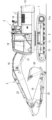
- FIG. 1 is an external view showing a hydraulic excavator as a working machine according to a first embodiment of the present invention.
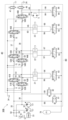
- FIG. 2 is a hydraulic circuit diagram showing the configuration of a hydraulic system included in the work machine according to the first embodiment.
- FIG. 3 is a diagram showing a part of the hydraulic system (circuit for driving the boom) of the working machine according to the first embodiment shown in FIG. 2 together with a control device.
- 3 is an opening area diagram of a pump directional control valve of the hydraulic system according to the first embodiment shown in FIG. 2.
- FIG. 3 is an opening area diagram of a pump flow control valve of the hydraulic system according to the first embodiment shown in FIG. 2.
- FIG. FIG. 4 is a block diagram showing control logic in the control device for the work machine according to the first embodiment shown in FIG. 3.
- FIG. 7 is a table used by the operation pattern calculation unit of the control device according to the first embodiment shown in FIG. 6.
- FIG. FIG. 2 is a hydraulic circuit diagram showing the configuration of a hydraulic system included in a working machine according to a second embodiment of the present invention.
- 9 is an opening area diagram of the pump directional control valve of the hydraulic system according to the second embodiment shown in FIG. 8.
- FIG. 9 is a block diagram showing the control logic of a control device for the hydraulic system according to the second embodiment shown in FIG. 8.
- FIG. FIG. 3 is a hydraulic circuit diagram showing the configuration of a hydraulic system included in a working machine according to a third embodiment of the present invention.
- 12 is an opening area diagram of the pump directional control valve of the hydraulic system according to the third embodiment shown in FIG. 11.
- FIG. 12 is a block diagram showing the control logic of a control device for the hydraulic system according to the third embodiment shown in FIG. 11.
- FIG. 14 is a characteristic diagram used by the function generator of the control device according to the third embodiment shown in
- FIG. 1 is an external view showing a hydraulic excavator as a working machine according to a first embodiment of the present invention. Here, the explanation will be made using the direction seen from the operator seated in the driver's seat.
- a hydraulic excavator as a working machine includes a self-propelled lower traveling body 1, an upper rotating body 2 rotatably mounted on the lower traveling body 1, and a front part of the upper rotating body 2 that can be tilted and raised.
- a front working device 3 is provided.
- the upper revolving body 2 is configured to swing relative to the lower traveling body 1 by a swing hydraulic motor 5, which is a hydraulic actuator.
- the lower traveling body 1 has, for example, crawler-type traveling devices 11 on both left and right sides (only the left side is shown in FIG. 1).
- the left and right traveling devices 11 are respectively driven by travel hydraulic motors 11a, which are hydraulic actuators.
- the upper revolving body 2 includes a revolving frame 13 as a support structure rotatably mounted on the lower traveling body 1, a cab 14 installed on the left front side of the revolving frame 13, and a rear end portion of the revolving frame 13.
- the vehicle is configured to include a counterweight 15 provided in the cab 14 and a machine room 16 provided between the cab 14 and the counterweight 15.
- a driver's seat (not shown) in which an operator sits, an operating device 7 (described later) (see FIG. 3, described later), and the like are arranged.
- the counterweight 15 is for balancing the weight with the front working device 3.
- the machine room 16 houses various devices such as hydraulic pumps 31 and 32, a prime mover 33, and control valve units 40 and 80 (see FIG. 2, which will be described later).
- the front work device 3 is for performing various works such as excavation work, and is, for example, an articulated work device configured by connecting a plurality of driven members so as to be rotatable in a vertical direction.
- the plurality of driven members include, for example, a boom 18, an arm 19, and a bucket 20 as a working tool.
- the base end of the boom 18 is supported by the front part of the revolving frame 13 of the upper revolving structure 2 so as to be rotatable in the vertical direction.
- a proximal end of an arm 19 is supported at the distal end of the boom 18 so as to be rotatable in the vertical direction.
- a proximal end portion of a bucket 20 is supported at the distal end portion of the arm 19 so as to be rotatable in the vertical direction.
- the boom 18, the arm 19, and the bucket 20 are operated by driving a boom cylinder 21, an arm cylinder 22, and a bucket cylinder 23, which are hydraulic actuators, respectively.
- FIG. 2 is a hydraulic circuit diagram showing the configuration of a hydraulic system included in the working machine according to the first embodiment.
- the hydraulic excavator is equipped with a hydraulic system 30 that operates the lower traveling body 1, the upper rotating body 2, and the front working device 3 (all shown in FIG. 1) using hydraulic pressure.
- the hydraulic system 30 includes a first hydraulic pump 31 (hereinafter referred to as a first pump) and a second hydraulic pump 32 (hereinafter referred to as a second pump) that discharge pressure oil, and a first pump 31 and a second pump 32.
- boom cylinder 21, arm cylinder 22, bucket cylinder 23, and swing hydraulic motor 5 as hydraulic actuators driven by pressure oil supplied from the tank, and a tank that stores return oil discharged from the hydraulic actuators 21, 22, 23, and 5. It is equipped with 34.
- a prime mover 33 is mechanically connected to the first pump 31 and the second pump 32, and the first pump 31 and the second pump 32 are driven by the power of the prime mover 33.
- the first pump 31 and the second pump 32 are, for example, variable displacement pumps, and have a regulator that adjusts the pump volume.
- the prime mover 33 is, for example, an engine or an electric motor.
- the first pump 31 and boom cylinder 21 are connected via a first boom directional control valve 41, and the second pump 32 and boom cylinder 21 are connected via a second boom directional control valve 42.
- the first pump 31 and arm cylinder 22 are connected via a first directional control valve 43 for arm, and the second pump 32 and arm cylinder 22 are connected via a second directional control valve 44 for arm.
- the first pump 31 and the bucket cylinder 23 are connected via a bucket directional control valve 45.
- the second pump 32 and the swing hydraulic motor 5 are connected via a swing direction control valve 46 .
- the first directional control valve 41 for boom controls the flow of pressure oil supplied from the first pump 31 to the boom cylinder 21, and also controls the flow of return oil discharged from the boom cylinder 21.
- the second boom directional control valve 42 controls the flow of pressure oil supplied from the second pump 32 to the boom cylinder 21 and also controls the flow of return oil from the boom cylinder 21 .
- the arm first directional control valve 43 controls the flow of pressure oil supplied from the first pump 31 to the arm cylinder 22 and also controls the flow of return oil discharged from the arm cylinder 22.
- the second direction control valve 44 for the arm controls the flow of pressure oil supplied from the second pump 32 to the arm cylinder 22 and also controls the flow of return oil from the arm cylinder 22.
- the bucket directional control valve 45 controls the flow of pressure oil supplied from the first pump 31 to the bucket cylinder 23 and also controls the flow of return oil discharged from the bucket cylinder 23.
- the swing direction control valve 46 controls the flow of pressure oil supplied from the second pump 32 to the swing hydraulic motor 5, and also controls the flow of return oil discharged from the swing hydraulic motor 5.
- the first boom directional control valve 41 controls the connection between the meter-in side of the boom cylinder 21 and the first pump 31, and also controls the connection between the meter-out side of the boom cylinder 21 and the tank 34.
- the second boom directional control valve 42 controls the connection between the meter-in side of the boom cylinder 21 and the second pump 32 and the connection between the meter-out side of the boom cylinder 21 and the tank 34 .
- the first directional control valve 43 for the arm controls the connection between the meter-in side of the arm cylinder 22 and the first pump 31, and also controls the connection between the meter-out side of the arm cylinder 22 and the tank 34.
- the second arm directional control valve 44 controls the connection between the meter-in side of the arm cylinder 22 and the second pump 32, and also controls the connection between the meter-out side of the arm cylinder 22 and the tank 34.
- the bucket directional control valve 45 controls the connection between the meter-in side of the bucket cylinder 23 and the first pump 31 and the connection between the meter-out side of the bucket cylinder 23 and the tank 34 .
- the swing direction control valve 46 controls the connection between the meter-in side of the swing hydraulic motor 5 and the second pump 32, and also controls the connection between the meter-out side of the swing hydraulic motor 5 and the tank 34.
- Each of the directional control valves 41 to 46 is, for example, an open center type valve that discharges pressure oil from the first pump 31 or the second pump 32 into the tank 34 when pressure oil is not supplied to the hydraulic actuators 21, 22, 23, 5.
- control valve Specifically, each of the directional control valves 41 to 46 is, for example, a spool valve with six ports and three positions (six ports: a pump port, a tank port, a pair of actuator ports, and a pair of center bypass ports).
- the first directional control valve 41 for the boom, the first directional control valve 43 for the arm, and the directional control valve 45 for the bucket are connected to the first center bypass line 37 connected to the first pump 31 via the first discharge line 35, for example. They are provided in this order from the upstream side, and are connected in tandem.
- the first center bypass line 37 connects the first pump 31 and the tank 34.
- a first center bypass cut valve 47 (hereinafter referred to as a first CB cut valve) is provided at the most downstream position in the first center bypass line 37.
- the first CB cut valve 47 controls the flow of pressure oil from the first pump 31 to the tank 34 via the first center bypass line 37.
- the second direction control valve 42 for the boom, the second direction control valve 44 for the arm, and the direction control valve 46 for swing are connected to the second center bypass line 38 connected to the second pump 32 via the second discharge line 36, for example. They are provided in this order from the upstream side, and are connected in tandem.
- the second center bypass line 38 connects the second pump 32 and the tank 34.
- a second center bypass cut valve 48 (hereinafter referred to as a second CB cut valve) is provided at the most downstream position in the second center bypass line 38.
- the second CB cut valve 48 controls the flow of pressure oil from the second pump 32 to the tank 34 via the second center bypass line 38.
- a first boom flow rate control valve 51 is provided upstream of the meter-in side (pump port side) of the first boom directional control valve 41.
- the first flow rate control valve 51 for the boom controls the flow rate of pressure oil supplied from the first pump 31 to the boom cylinder 21 via the first directional control valve 41 for the boom.
- a second boom flow rate control valve 52 is provided upstream of the meter-in side (pump port side) of the second boom directional control valve 42 .
- the second flow rate control valve 52 for boom controls the flow rate of pressure oil supplied from the second pump 32 to the boom cylinder 21 via the second directional control valve 42 for boom.
- a first arm flow control valve 53 is provided upstream of the meter-in side (pump port side) of the first arm directional control valve 43.
- the arm first flow control valve 53 controls the flow rate of pressure oil supplied from the first pump 31 to the arm cylinder 22 via the arm first direction control valve 43.
- a second arm flow rate control valve 54 is provided upstream of the meter-in side (pump port side) of the second arm directional control valve 44 .
- the second arm flow control valve 54 controls the flow rate of pressure oil supplied from the second pump 32 to the arm cylinder 22 via the arm second directional control valve 44 .
- a bucket flow rate control valve 55 is provided upstream of the meter-in side (pump port side) of the bucket directional control valve 45.
- the bucket flow control valve 55 controls the flow rate of pressure oil supplied from the first pump 31 to the bucket cylinder 23 via the bucket directional control valve 45.
- a swirling flow rate control valve 56 is provided upstream of the meter-in side (pump port side) of the swirling directional control valve 46.
- the swing flow rate control valve 56 controls the flow rate of pressure oil supplied from the second pump 32 to the swing hydraulic motor 5 via the swing direction control valve 46.
- the first directional control valve 41 for the boom is connected to the bottom side and the rod side of the boom cylinder 21 via the first actuator lines 61, 61 for the boom
- the second directional control valve 42 for the boom is connected to the second directional control valve 42 for the boom. It is connected to the bottom side and rod side of the boom cylinder 21 via actuator lines 62, 62.
- the first directional control valve 43 for the arm is connected to the bottom side and the rod side of the arm cylinder 22 via the first actuator lines 63, 63 for the arm
- the second directional control valve 44 for the arm is connected to the second directional control valve 44 for the arm. It is connected to the bottom side and rod side of the arm cylinder 22 via actuator lines 64, 64.
- the bucket directional control valve 45 is connected to the bottom side and the rod side of the bucket cylinder 23 via first bucket actuator lines 65, 65.
- the swing direction control valve 46 is connected to the first port side and the second port side of the swing hydraulic motor 5 via first swing actuator lines 66 , 66 .
- the meter-out side (tank port side) of the first boom directional control valve 41 is connected to the tank 34 via the boom first return line 71
- the meter-out side (tank port side) of the second boom directional control valve 42 is connected to the tank 34 via the boom first return line 71.
- tank port side is connected to the tank 34 via a second return line 72 for the boom.
- the meter-out side (tank port side) of the first directional control valve 43 for the arm is connected to the tank 34 via the first return line 73 for the arm
- the meter-out side (tank port side) of the second directional control valve 44 for the arm is connected to the tank 34 via the first return line 73 for the arm.
- tank port side is connected to the tank 34 via a second return line 74 for the arm.
- a meter-out side (tank port side) of the bucket directional control valve 45 is connected to the tank 34 via a bucket return line 75.
- the meter-out side (tank port side) of the swing direction control valve 46 is connected to the tank 34 via a swing return line 76 .
- the above-mentioned directional control valves 41 to 46, flow rate control valves 51 to 56, and CB cut valves 47 and 48 constitute a first control valve unit 40 as an assembly of a plurality of control valves.
- first pump 31 and the second pump 32 are connected to the tank 34 via a relief valve 57.
- the relief valve 57 opens when the pressure in the hydraulic circuit becomes equal to or higher than a set pressure, and has the function of preventing damage to hydraulic equipment due to excessive pressure rise.
- the relief valve 57 is connected to the first discharge line 35 via a first check valve 58 and to the second discharge line 36 via a second check valve 59.
- the first check valve 58 and the second check valve 59 allow flow from the first pump 31 and second pump 32 side to the relief valve 57 side, while allowing flow from the relief valve 57 side to the first discharge line 35 and the second discharge line 35. This prevents the flow to line 36.
- the hydraulic system 30 further includes an accumulator 78.
- the accumulator 78 stores and accumulates pressure oil supplied from the first pump 31 and the second pump 32, and supplies the stored pressure oil to the hydraulic actuators 21, 22, 23, and 5.
- the accumulator 78 is connected to the first pump 31 via a first accumulator flow control valve 81 (hereinafter referred to as ACC first flow control valve), and is also connected to the first pump 31 via a second accumulator flow control valve 82 (hereinafter referred to as ACC first flow control valve). It is connected to the second pump 32 via a second flow control valve for ACC (referred to as a second flow control valve for ACC).
- the first flow control valve 81 for ACC is connected to the first pump 31 via a first supply line 88
- the second flow control valve 82 for ACC is connected to the second pump 32 via a second supply line 89.
- the accumulator 78 is connected to the boom cylinder 21 via a first direction control valve 83 for an accumulator (hereinafter referred to as a first direction control valve for ACC).
- the arm cylinder 22 is connected to the bucket cylinder 23 via the third direction control valve 85 for the accumulator (hereinafter referred to as the third direction control valve for ACC) via the fourth direction control valve 86 for the accumulator (hereinafter referred to as the third direction control valve for ACC). It is connected to the swing hydraulic motor 5 via an ACC fourth direction control valve (hereinafter referred to as a fourth directional control valve for ACC).
- the first directional control valve 83 for ACC controls the flow (direction and flow rate) of pressure oil supplied from the accumulator 78 to the boom cylinder 21 .
- the second directional control valve 84 for ACC controls the flow (direction and flow rate) of pressure oil supplied from the accumulator 78 to the arm cylinder 22.
- the third direction control valve 85 for ACC controls the flow (direction and flow rate) of pressure oil supplied from the accumulator 78 to the bucket cylinder 23 .
- the fourth direction control valve 86 for ACC controls the flow (direction and flow rate) of the pressure oil supplied from the accumulator 78 to the swing hydraulic motor 5.
- the first directional control valve 83 for ACC is connected to the accumulator 78 via a boom accumulator line 91, and is also connected to the bottom side and rod side of the boom cylinder 21 via third boom actuator lines 96, 96. has been done.
- the second directional control valve 84 for ACC is connected to the accumulator 78 via the arm accumulator line 92, and is also connected to the bottom side and rod side of the arm cylinder 22 via third arm actuator lines 97, 97. has been done.
- the third directional control valve 85 for ACC is connected to the accumulator 78 via a bucket accumulator line 93, and is also connected to the bottom side and rod side of the bucket cylinder 23 via second bucket actuator lines 98, 98. has been done.
- the fourth directional control valve 86 for ACC is connected to the accumulator 78 via a swing accumulator line 94, and is connected to the first port side and the first port side of the swing hydraulic motor 5 via second swing actuator lines 99, 99. Connected to the 2 port side.
- the ACC directional control valves 83 to 86 are composed of, for example, 3-port, 3-position spool valves.
- the three ports are an accumulator port connected to the accumulator 78, and a pair of actuators connected to the bottom side and rod side of the hydraulic cylinders 21, 22, 23 or the first port side and the second port side of the hydraulic motor 5. It is a port. That is, the ACC directional control valves 83 to 86 have a configuration without a tank port. That is, the ACC directional control valves 83 to 86 control the connection between the meter-in sides of the hydraulic actuators 21, 22, 23, and 5 and the accumulator 78.
- the above-described ACC flow rate control valves 81, 82 and ACC directional control valves 83 to 86 constitute a second control valve unit 80 as an assembly of a plurality of control valves.
- the ACC directional control valves 83 to 86 are provided with a meter-out circuit such as a return line for connecting to the tank 34 and a flow control valve for controlling the flow of return oil. There is no configuration.
- FIG. 3 is an excerpt of a hydraulic circuit for a boom cylinder from the hydraulic system shown in FIG. 2, and is a diagram showing objects to be controlled by the control device.
- the hydraulic system 30 is configured to be controlled by commands from the control device 100.
- the control device 100 In order to simplify the description of the control of the hydraulic system 30 by the control device 100, only the hydraulic circuit for driving the boom cylinder 21 in the hydraulic system 30 will be described. However, the control of the hydraulic circuit that drives the arm cylinder 22, the bucket cylinder 23, and the swing hydraulic motor 5 in the hydraulic system 30 is also similar to the description below.
- an operation signal from the operating device 7 is input to the control device 100.
- the operating device 7 instructs the operations of the boom 18, arm 19, and bucket 20 of the front working device 3 and the turning operation of the revolving upper structure 2.
- the operating device 7 outputs operating signals (electrical signals) for boom operation, arm operation, bucket operation, and turning operation to the control device 100 according to the operating direction and amount operated by the operator.
- the control device 100 controls the first boom directional control valve 41 , the second boom directional control valve 42 , and the first boom flow rate control valve of the hydraulic system 30 in response to a boom operation operation signal from the operating device 7 .
- 51, second flow control valve for boom 52, first CB cut valve 47, second CB cut valve 48, first flow control valve for ACC 81, second flow control valve for ACC 82, first direction control valve for ACC 83 It controls the driving of each control valve.
- operation signals electrical signals for arm operation, bucket operation, and rotation operation other than boom operation are input.
- the first boom directional control valve 41 and the second boom directional control valve 42 are configured to switch the spool position (spool stroke) in response to a command (for example, an electromagnetic command) from the control device 100, for example. .
- the first boom directional control valve 41 and the second boom directional control valve 42 have a meter-in passage, a meter-out passage, and a center bypass passage.
- the meter-in passage is a passage for connecting the first discharge line 35 (first pump 31) or the second discharge line 36 (second pump 32) to the meter-in side of the boom cylinder 21.
- the meter-out passage is a passage for connecting the meter-out side of the boom cylinder 21 to the tank 34.
- the center bypass passage is for connecting the first discharge line 35 (first pump 31) or the second discharge line 36 (second pump 32) to the first center bypass line 37 or the second center bypass line 38 (tank 34). It is a passageway.
- first boom directional control valve 41 and the second boom directional control valve 42 by switching the spool position, three openings are made: the opening area of the meter-in passage, the opening area of the meter-out passage, and the opening area of the center bypass passage. The area ratio changes.
- the first boom directional control valve 41 and the second boom directional control valve 42 of this embodiment have, for example, the opening characteristics shown in FIG. 4.
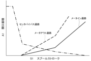
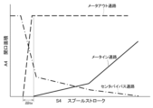
- FIG. 4 is an opening area diagram of the first boom directional control valve and the boom second directional control valve.
- the horizontal axis S1 represents the spool stroke
- the vertical axis A1 represents the opening area of each of the meter-in passage, meter-out passage, and center bypass passage.
- the solid line shows the characteristic diagram of the meter-in passage
- the broken line shows the characteristic diagram of the meter-out passage
- the spool stroke (spool position) of the first boom directional control valve 41 and the second boom directional control valve 42 has a characteristic that increases in proportion to the amount of operation of the operating device 7.
- the center bypass passage is configured such that its opening area is narrowed as the spool stroke increases.
- the meter-in passage and the meter-out passage are configured in advance so that they begin to open simultaneously at a predetermined spool stroke (predetermined spool position), and as the spool stroke increases from there, the opening area gradually increases. In the case of such opening characteristics, when the spool stroke increases, the first pump 31 or the second pump 32 shown in FIG. The flow rate of the pressure oil flowing out to the tank 34 through is throttled.
- the pressure oil of the first pump 31 or the second pump 32 is supplied to the boom cylinder 21 via the first boom directional control valve 41 or the second boom directional control valve 42 (meter-in passage), and
- the return oil discharged from 21 is connected to the first boom actuator lines 61, 61 or the second boom actuator lines 62, 62 and the first boom directional control valve 41 or the second boom directional control valve 42 (meter-out passage). It is discharged into the tank 34 via the first return line 71 for the boom or the second return line 72 for the boom.
- the first boom flow control valve 51 and the second boom flow control valve 52 are configured so that their strokes (spool positions) can be switched in response to commands from the control device 100 (for example, electromagnetic commands).
- the first boom flow control valve 51 and the second boom flow control valve 52 have, for example, opening characteristics shown in FIG. 5 .
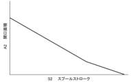
- FIG. 5 is an opening area diagram of the first boom flow control valve and the second boom flow control valve.
- the horizontal axis S2 represents the stroke
- the vertical axis A2 represents the opening area.
- the opening areas of the first boom flow control valve 51 and the second boom flow control valve 52 have normally open characteristics. That is, when the spool is not displaced, the opening area is maximum, and as the stroke increases, the opening area gradually decreases and closes. Note that the strokes of the first boom flow control valve 51 and the boom second flow control valve 52 are different from those of the boom first direction control valve 41 and the boom second direction control valve 42, and It is controlled according to the situation and not according to the amount of operation.
- the first CB cut valve 47 and the second CB cut valve 48 are configured so that their strokes (spool positions) can be switched according to commands from the control device 100 (for example, electromagnetic commands), and have normally open characteristics. It is a control valve with Further, the first flow control valve 81 for ACC and the second flow control valve 82 for ACC are configured so that the stroke (spool position) can be switched according to a command (for example, an electromagnetic command) from the control device 100. , for example, a control valve with normally closed characteristics.
- the first direction control valve 83 for ACC is configured such that the spool stroke (spool position) is switched according to a command (for example, an electromagnetic command) from the control device 100, and for example, as the spool stroke increases, the opening This is a control valve that has the characteristic of increasing area.
- FIG. 6 is a block diagram showing the control logic in the control device for the working machine according to the first embodiment shown in FIG.
- FIG. 7 is a table used by the operation pattern calculating section of the control device according to the first embodiment shown in FIG.
- the control device 100 includes, as a hardware configuration, a storage device 100a consisting of a RAM, ROM, etc., and a processing device 100b consisting of a CPU, MPU, etc.
- the storage device 100a includes directional control valves 41 to 46 for the pumps 31 and 32 in the hydraulic system 30, each flow rate control valve 51 to 56, each CB cut valve 47 and 48, and each flow rate control valve 81 for the accumulator 78. , 82 and the various directional control valves 83 to 86 are stored in advance.
- the processing device 100b implements various functions by appropriately reading programs and various information from the storage device 100a and executing processes according to the programs.
- control for driving the boom cylinder 21 by supplying pressure oil from the first pump 31, the second pump 32, and the accumulator 78 will be described.
- the control for driving the arm cylinder 22, bucket cylinder 23, and swing hydraulic motor 5 by supplying pressure oil from the first pump 31, the second pump 32, and the accumulator 78 is the same as that for the boom cylinder 21, so these controls will be explained below. is omitted.
- the control device 100 of this embodiment executes the following control.
- the control device 100 controls the drive of the first boom directional control valve 41 so that the pressure oil is supplied from the first pump 31 to the boom cylinder 21.
- the return oil discharged from the boom cylinder 21 is controlled to be discharged to the tank 34 via the first boom directional control valve 41.
- the pressure oil of the second pump 32 is supplied to the boom cylinder 21
- the flow of the pressure oil supplied from the second pump 32 to the boom cylinder 21 is controlled by controlling the drive of the second boom directional control valve 42.
- the return oil of the boom cylinder 21 is controlled to be discharged into the tank 34 via the second boom directional control valve 42.
- the pressure oil stored in the accumulator 78 is supplied to the boom cylinder 21
- the pressure oil supplied from the accumulator 78 to the boom cylinder 21 is controlled by controlling the drive of the first directional control valve 83 for ACC.
- the first directional control valve 41 By controlling the flow and driving the first boom directional control valve 41, the return oil of the boom cylinder 21 is discharged into the tank 34 via the boom first directional control valve 41, and the boom first directional control valve 41 is discharged.
- the drive of the first flow rate control valve 51 the pressure oil supplied from the first pump 31 to the boom cylinder 21 via the first boom directional control valve 41 is controlled to be finally shut off.
- the control device 100 responds to the input of the operation amount (operation signal) of each operation (boom operation, arm operation, bucket operation, swing operation) of the operation device 7 by, for example, as shown in FIG.
- a boom first spool control command C1 commands the driving of the first boom directional control valve 41
- a boom second spool control command C2 commands the driving of the boom second directional control valve 42
- Boom first flow control command C3 that commands the drive of the first boom flow control valve 51
- boom second flow control command C4 that commands the drive of the boom second flow control valve 52
- first directional control valve 83 for the ACC.
- a boom ACC flow rate control command C5 is output that commands the drive of the boom ACC flow rate control command C5.
- the control logic of the control device 100 includes an operation pattern calculation unit 101 that determines the operation pattern of the hydraulic excavator based on the operation amount (operation signal) of each operation from the operation device 7;
- the integrator 103 corresponds to the first direction control valve 41 for the boom, the second direction control valve 42 for the boom, and the first direction control valve 83 for the ACC among the plurality of control valves 41, 42, 51, 52, and 83.
- 104, 105, function generators 111, 112, 113, 114, 115 and output converters 121, 122, 123, 124, 125 corresponding to each control valve 41, 42, 51, 52, 83 to be controlled. have.
- the operation pattern calculation unit 101 determines the operation pattern performed by the hydraulic excavator based on the operation amount (operation signal) of each operation from the operating device 7, and controls the hydraulic system 30 to optimally operate for each determined operation pattern. This is to set the driving state of each target control valve 41, 42, 51, 52, 83. That is, it is determined to which hydraulic actuator 21, 22, 23, 5 each hydraulic source of the first pump 31, second pump 32, and accumulator 78 is connected according to each operation pattern, and each determined hydraulic source 31, The drive state of each control valve 41, 42, 51, 52, 83 to be controlled is set so that pressure oil can be supplied to the connection destination of valve 32, 78. Specifically, the operation pattern calculation unit 101 sets the driving state of each of the control valves 41, 42, 51, 52, and 83 to be controlled, with reference to the information (table) shown in FIG. 7, for example.
- the operation patterns include excavation operation, swing boom raising operation, and boom raising individual operation, which are typical operations of a hydraulic excavator.
- the excavation operation is a three-component operation in which the operations of three link members, the boom 18, the arm 19, and the bucket 20, which constitute the front working device 3 are combined. That is, the excavation operation is an operation in which the boom cylinder 21, arm cylinder 22, and bucket cylinder 23 are simultaneously driven.
- the revolving boom raising operation is a two-component operation in which the revolving operation of the upper revolving body 2 and the operation of the boom 18 are combined. That is, this is an operation in which the swing hydraulic motor 5 and the boom cylinder 21 are driven simultaneously.
- the independent boom raising operation is an independent operation in which only the boom 18 is operated by driving only the boom cylinder 21 in the extension direction.
- the table shown in FIG. 7 shows the connection destinations (pressure oil supply destinations) of each hydraulic power source 31, 32, and 78 in order to optimally operate the hydraulic system 30 for each operation pattern.
- pump 1 indicates the first pump
- pump 2 indicates the second pump
- ACC indicates the accumulator 78.
- BM indicates the boom cylinder 21
- AM indicates the arm cylinder 22
- BK indicates the bucket cylinder 23
- SW indicates the swing hydraulic motor 5.
- the first pump 31 is connected to the boom cylinder 21 and the bucket cylinder 23. This means that the first boom directional control valve 41 and the bucket directional control valve 45 shown in FIG. 2 are driven. Further, the second pump 32 is connected to the arm cylinder 22. This means that the second arm directional control valve 44 shown in FIG. 2 is driven. Note that the accumulator 78 is not connected to any of the hydraulic actuators 21, 22, 23, and 5.
- the second pump 32 is connected to the swing hydraulic motor 5.
- the accumulator 78 is connected to the boom cylinder 21.
- the return oil discharged from the boom cylinder 21 is directed to the first direction control valve 83 for ACC. It is not possible to discharge into tank 34 via control valve 83.
- the description of (BM) as the connection destination of the pump 1 in the swinging boom raising operation means that the first directional control valve 41 for the boom for connecting the first pump 31 to the boom cylinder 21 is connected to the boom cylinder 21.
- the meter-out side of the boom cylinder 21 is connected to the tank 34, and by driving the first boom flow rate control valve 51, the first direction control valve 41 for the boom is connected from the first pump 31. This indicates that the supply of pressurized oil to the boom cylinder 21 via the above is cut off.
- the operation pattern calculation unit 101 sets the drive state of each of the control valves 41, 42, 51, 52, and 83 to be controlled, as described above, according to the result of the determination of the operation pattern.
- the drive state setting results for each control valve 41, 42, 51, 52, 83 are output to the corresponding integrator 103, 104, 105 or function generator 113, 114.
- the operation pattern calculation unit 101 outputs to the integrator 103 the setting result of "1" for driving or “0" for not driving as the driving state of the first boom directional control valve 41. . Further, as the driving state of the second boom directional control valve 42, a setting result of "1” for driving or “0” for not driving is output to the integrator 104. Further, as the driving state of the first ACC directional control valve 83, the setting result of “1” for driving or “0” for not driving is output to the integrator 105. With such an output of the operation pattern calculation unit 101, it is possible to control whether or not to drive the first direction control valve 41 for the boom, the second direction control valve 42 for the boom, and the first direction control valve 83 for the ACC. There is.
- the operation pattern calculation unit 101 determines the driving state of the first flow rate control valve 51 for the boom when the first pump 31 is connected to the meter-in side of the boom cylinder 21 via the first directional control valve 41 for the boom (excavation (in the case of a single boom raising operation), a setting result for increasing the opening area is output to the function generator 113. Furthermore, as the driving state of the first boom flow rate control valve 51, when the meter-out side of the boom cylinder 21 is connected to the tank 34 via the first boom directional control valve 41 (in the case of a swinging boom raising operation), The setting result for closing the opening is output to the function generator 113.
- the operation pattern calculation unit 101 determines the driving state of the second boom flow rate control valve 52 when the second pump 32 is connected to the meter-in side of the boom cylinder 21 via the second boom directional control valve 42 (boom In the case of a single raising operation), a setting result for increasing the opening area is output to the function generator 114.
- a function is generated to close the opening. output to the device 114.
- the integrator 103 for the first directional control valve 41 for the boom uses the operation amount (operation signal) of the boom operation of the operating device 7 and the setting result of the driving state for the first directional control valve 41 for the boom by the operation pattern calculation unit 101. This is to integrate the following.
- the integration result is output to the function generator 111 for the first directional control valve 41 for the boom.
- the operation signal of the boom operation of the operation device 7 is a signal corresponding to the operation amount of the boom operation, and has a value of, for example, 0 to 100 [%].
- the setting result of the driving state of the first directional control valve 41 for the boom by the operation pattern calculation unit 101 is "0" when the boom is not driven, or "1" when the boom is driven.
- the integrator 103 outputs the same value as the boom operation operation signal of the operating device 7 when the first boom directional control valve 41 is driven, and outputs "0" when the boom first directional control valve 41 is not driven. " value (signal) is output to the function generator 111.
- the function generator 111 calculates the opening area of the first boom directional control valve 41 according to the output (integration result) of the integrator 103. The calculation result is output to the output converter 121 for the first directional control valve 41 for the boom.
- the output conversion unit 121 is a calculation unit that converts the opening area of the first directional control valve 41 for the boom, which is the output (calculation result) of the function generator 111, into a displacement amount (stroke) of the spool.
- the calculation result is output to the boom first directional control valve 41 as a boom first spool control command C1. Thereby, the first direction control valve 41 for the boom is controlled to a desired stroke and opening area.
- the integrator 104, function generator 112, and output converter 122 for the second boom directional control valve 42 are also the same as in the case of the first boom directional control valve 41 described above. That is, the integrator 104 uses the operation signal (0 to 100) of the boom operation of the operating device 7 and the setting result of the drive state for the second boom directional control valve 42 of the operation pattern calculation unit 101 (“0” when not driven). or "1" in the case of driving, and outputs the integration result to the function generator 112.
- the function generator 112 calculates the opening area of the second boom directional control valve 42 according to the output of the integrator 104 and outputs the calculation result to the output converter 122.
- the output conversion unit 122 converts the opening area of the second direction control valve 42 for the boom, which is the output of the function generator 112, into a displacement amount of the spool, and uses the calculation result as a boom second spool control command C2 to output the second direction control valve for the boom. Output to control valve 42. Thereby, the second boom directional control valve 42 is controlled to a desired stroke and opening area.
- the integrator 105, function generator 115, and output converter 125 for the first ACC directional control valve 83 are also the same as in the case of the first boom directional control valve 41 described above. That is, the integrator 105 uses the operation signal (0 to 100) of the boom operation of the operation device 7 and the setting result of the drive state for the first directional control valve 83 for ACC of the operation pattern calculation unit 101 (“0” when not driven). or "1" in the case of driving, and outputs the integration result to the function generator 115.
- the function generator 115 calculates the opening area of the first ACC directional control valve 83 according to the output of the integrator 105 and outputs the calculation result to the output converter 125.
- the output converter 125 converts the opening area of the first directional control valve 83 for ACC, which is the output of the function generator 115, into the displacement amount of the spool of the first directional control valve 83 for ACC, and uses the calculation result to control the boom ACC flow rate. It is output to the first direction control valve 83 for ACC as a command C5. Thereby, the first direction control valve 83 for ACC is controlled to a desired stroke and opening area.
- the function generator 113 for the first flow rate control valve 51 for the boom controls the first flow rate for the boom according to the setting result (signal) for the driving state of the first flow rate control valve 51 for the boom from the operation pattern calculation unit 101. It performs calculations for controlling the opening area of the valve 51. The calculation result is output to the output conversion section 123 for the first boom flow control valve 51.
- the function generator 113 increases the opening area according to the output of the operation pattern calculation unit 101 when the first pump 31 is connected to the boom cylinder 21 (in the case of excavation operation or boom raising operation alone in FIG. 7). (Small the stroke) Output the calculation result.
- the boom cylinder 21 is not driven or when the meter-in side of the boom cylinder 21 is connected only to the accumulator 78 (in the case of the swinging boom raising operation in FIG. 7)
- the opening is adjusted according to the output of the operation pattern calculation unit 101. Outputs the result of closing (increasing the stroke) operation.
- the output conversion unit 123 calculates a boom first flow rate control command C3 based on the output of the function generator 113 and outputs it to the boom first flow rate control valve 51.
- the first flow rate control valve 51 for the boom is controlled to a desired stroke and opening area.
- the first flow rate control valve 51 for the boom is controlled to close its opening. Shocks occur when the stroke changes suddenly. Therefore, the first flow rate control valve 51 for the boom is controlled not by ON/OFF switching control but by gradually changing the stroke and finally closing it. That is, the first flow rate control valve 51 for the boom is driven so that the flow of pressure oil from the first pump 31 to the boom cylinder 21 via the first directional control valve 41 for the boom is gradually throttled and then finally shut off. Control.
- the function generator 114 and output converter 124 for the second boom flow control valve 52 are also the same as in the case of the above-described first boom flow control valve 51.
- the function generator 114 performs a calculation for controlling the opening area of the second flow rate control valve 52 for the boom according to the setting result (signal) for the driving state of the second flow rate control valve 52 for the boom from the operation pattern calculation unit 101.
- the calculation result is output to the output conversion section 124.
- the output conversion unit 124 calculates a boom second flow rate control command C4 based on the output of the function generator 114 and outputs it to the boom second flow rate control valve 52. Thereby, the second flow rate control valve 52 for the boom is controlled to a desired stroke and opening area.
- the control device 100 shown in FIG. 6 connects the first pump 31 shown in FIG. In order to connect the second pump 32 to the arm cylinder 22, the first directional control valve 41 for the boom and the directional control valve 45 for the bucket are controlled to be driven, and the second directional control valve 44 for the arm is driven to connect the second pump 32 to the arm cylinder 22. control to do so.
- the pressure oil of the first pump 31 is supplied to the boom cylinder 21 via the first boom flow control valve 51 and the first boom directional control valve 41.
- the return oil discharged from the boom cylinder 21 is guided from the first boom directional control valve 41 to the tank 34 via the first boom return line 71.
- pressure oil from the first pump 31 is supplied to the bucket cylinder 23 via the bucket flow control valve 55 and the bucket directional control valve 45.
- the return oil discharged from the bucket cylinder 23 is guided from the bucket directional control valve 45 to the tank 34 via the bucket return line 75.
- the pressure oil of the second pump 32 is supplied to the arm cylinder 22 via the second flow rate control valve 54 for the arm and the second direction control valve 44 for the arm.
- the return oil discharged from the arm cylinder 22 is guided from the second arm directional control valve 44 to the tank 34 via the second arm return line 74.
- control device 100 determines that it is a "swing boom raising operation"
- it controls the swing direction control valve 46 to connect the second pump 32 to the swing hydraulic motor 5, and also controls the accumulator 78.
- Control is performed to drive the first ACC directional control valve 83 for connection to the boom cylinder 21 .
- the control device 100 further performs control to drive the boom first direction control valve 41 to connect the meter-out side of the boom cylinder 21 and the tank 34, and also controls the boom first flow control valve 51 to connect the meter-out side of the boom cylinder 21 and the tank 34. Control is performed to gradually narrow the opening and then finally close it.
- the pressure oil of the second pump 32 is supplied to the swing hydraulic motor 5 via the swing flow rate control valve 56 and the swing direction control valve 46.
- the return oil discharged from the swing hydraulic motor 5 is guided to the tank 34 by the swing return line 76 via the swing direction control valve 46.
- the pressure oil of the accumulator 78 is supplied to the boom cylinder 21 via the first directional control valve 83 for ACC.
- the return oil of the boom cylinder 21 is guided from the first actuator line 61 for the boom to the tank 34 by the first return line 71 for the boom via the first directional control valve 41 for the boom.
- control device 100 determines that the “boom raising operation is independent”
- the control device 100 performs a first direction for the boom in order to connect the three hydraulic power sources of the first pump 31, the second pump 32, and the accumulator 78 to the boom cylinder 21.
- Control valve 41, boom second direction control valve 42, and ACC first direction control valve 83 are controlled to be driven.
- the pressure oil of the first pump 31 is supplied to the boom cylinder 21 via the first boom flow control valve 51 and the first boom directional control valve 41.
- pressure oil from the second pump 32 is supplied to the boom cylinder 21 via the second flow control valve 52 for the boom and the second directional control valve 42 for the boom.
- the pressure oil of the accumulator 78 is supplied to the boom cylinder 21 via the first directional control valve 83 for ACC.
- the return oil of the boom cylinder 21 is guided from the first boom directional control valve 41 to the tank 34 via the boom first return line 71, and from the boom second directional control valve 42 to the boom second return oil. It is led to tank 34 via line 72.
- the control device 100 can supply pressure oil to each hydraulic actuator 21 , 22 , 23 , 5 only from the hydraulic pressure source of the accumulator 78 . , 23, 5, and the directional control valves 41 to 46 and flow rate control valves 51 to 46 corresponding to each hydraulic actuator 21, 22, 23, 5. 56 is controlled.
- each hydraulic actuator 21, 22 is in a state where the supply of pressure oil from the first pump 31 or the second pump 32 to each hydraulic actuator 21, 22, 23, 5 via each directional control valve 41 to 46 is cut off.
- 23, 5 are connected to the tank 34, each hydraulic actuator 21, 22, 23, 5 can be driven only by pressure oil from the accumulator 78.
- each hydraulic actuator 21, 22, 23, 5 can be supplied with pressure oil. Furthermore, it is also possible to simultaneously supply pressure oil to each of the hydraulic actuators 21, 22, 23, and 5 from three hydraulic sources: the first pump 31, the second pump 32, and the accumulator 78.
- the hydraulic excavator (work machine) includes a first pump 31 and a second pump 32 (hydraulic pump) that discharge pressure oil, and a first pump 31 and a second pump 32 (hydraulic pump).
- Hydraulic actuators 21, 22, 23, 5 driven by pressure oil discharged from the hydraulic actuators 21, 22, 23, 5, a tank 34 that stores return oil discharged from the hydraulic actuators 21, 22, 23, 5, and a first pump 31 and a second pump.
- 32 (hydraulic pump) and an accumulator 78 that stores the pressure oil discharged from the hydraulic pump and supplies the accumulated pressure oil to the hydraulic actuators 21, 22, 23, and 5, and the meter-in side of the hydraulic actuators 21, 22, 23, and 5.
- first pump 31 or the second pump 32 hydroaulic pump
- second pump directional control valves 41 to 46 that control the connection between the meter-out side of the hydraulic actuators 21, 22, 23, and 5 and the tank 34.
- first control valve first control valve
- direction control valves 83 to 86 second control valves that control the connection between the meter-in side of the hydraulic actuators 21, 22, 23, 5 and the accumulator 78.
- the control device 100 controls the direction so that the meter-in side of the hydraulic actuators 21, 22, 23, 5 and the accumulator 78 are connected.
- Control valves 83 to 86 are driven, and directional control valves 41 to 46 (first control valves) are connected to connect the meter-out sides of hydraulic actuators 21, 22, 23, and 5 to tank 34. Finally, the flow of pressure oil from the first pump 31 or the second pump 32 (hydraulic pump) to the hydraulic actuators 21, 22, 23, 5 via the directional control valves 41 to 46 (first control valves) is controlled.
- the flow rate control valves 51 to 56 are configured to be driven to shut off the flow rate.
- the return oil of the hydraulic actuators 21, 22, 23, and 5 can be discharged to the tank 34 via the directional control valves 41 to 46 (first control valves). That is, control of the flow on the meter-out side of the hydraulic actuators 21, 22, 23, and 5 can be realized using only the directional control valves 41 to 46 (first control valves). Therefore, there is no need to provide a meter-out circuit such as a return oil path or a flow rate control valve for the directional control valves 83 to 86 (second control valves), and other than the first pump 31 and second pump 32 (hydraulic pump) In the hydraulic system 30, which is capable of supplying pressure oil from the accumulator 78 to the hydraulic actuators 21, 22, 23, and 5, the configuration can be prevented from becoming complicated.
- the directional control valves 41 to 46 are for connecting the first pump 31 or the second pump 32 (hydraulic pump) to the hydraulic actuators 21, 22, 23, 5.
- Both the meter-in passage and the meter-out passage for connecting the tank 34 to the hydraulic actuators 21, 22, 23, and 5 open and start communicating at the same time at a predetermined stroke, and both open at a stroke larger than the predetermined stroke.
- the passages have an open characteristic such that the passages together form an open state.
- the flow rate control mechanism includes flow rate control valves 51 to 56 different from the directional control valves 41 to 46 (first control valves).
- the control device 100 controls the meter-out of the hydraulic actuators 21, 22, 23, and 5 by individually controlling the direction control valves 41 to 46 (first control valves) and the flow rate control valves 51 to 56.
- the directional control valves 41 to 46 are used to secure the connection between the side and the tank 34 and to cut off the connection between the first pump 31 or the second pump 32 (hydraulic pump) and the hydraulic actuators 21, 22, 23, 5.
- (first control valve) and flow control valves 51 to 56 are easy to control.
- the difference between the second embodiment of the working machine of the present invention and the first embodiment is that the openings of the directional control valves 41A, 42A, 43A, 44A, 45A, and 46A of the hydraulic system 30A shown in FIG.
- the characteristics are different, and the control method for the hydraulic system 30A of the control device 100A shown in FIG. 10 is different depending on the difference in the opening characteristics of the directional control valves 41A to 46A.
- the directional control valves 41A to 46A have a characteristic that the center bypass passage does not close even if the spool position is switched.
- the directional control valves 41A to 46A have opening characteristics shown in FIG. 9, for example.
- FIG. 9 is an opening area diagram of each of the directional control valves 41A to 46A of the hydraulic system 30A shown in FIG.
- the horizontal axis S3 indicates the spool stroke
- the vertical axis A3 indicates the opening area of each of the meter-in passage, meter-out passage, and center bypass passage.
- the solid line shows the characteristic diagram of the meter-in passage
- the broken line shows the characteristic diagram of the meter-out passage
- the one-dot chain line shows the characteristic diagram of the center bypass passage.
- the spool stroke (spool position) of the directional control valves 41A to 46A has a characteristic that increases in proportion to the amount of operation of each operation of the operating device 7, as in the case of the directional control valves 41 to 46 of the first embodiment. ing.
- the meter-in passage and the meter-out passage begin to open simultaneously at a predetermined spool stroke (predetermined spool position), and as the spool stroke increases from there, the opening area gradually increases. It is preconfigured as follows.
- the opening area of the center bypass passage is constant regardless of the increase or decrease of the spool stroke. That is, the directional control valves 41A to 46A have an opening characteristic in which the opening amount (opening area of the center bypass passage) with respect to the first center bypass line 37 or the second center bypass line 38 is constant over the entire stroke.
- FIG. 10 is a block diagram showing the control logic of a control device for the hydraulic system shown in FIG. 8.
- the control device 100A controls the first center bypass line 37 connecting the first pump 31 and the tank 34 in response to the fact that the opening area of the center bypass passage of the directional control valves 41A to 46A is constant over the entire spool stroke.
- the flow of pressure oil is controlled only by the first CB cut valve 47, and the flow of pressure oil in the second center bypass line 38 connecting the second pump 32 and the tank 34 is controlled only by the second CB cut valve 48.
- a control device 100A shown in FIG. 10 includes a first CB cut valve 47 and a second CB cut valve 48 in addition to the control valves 41, 42, 51, 52, and 83 in the first embodiment. There is.
- the control device 100A issues a first cut control command C6 that commands the drive of the first CB cut valve 47 and a command to drive the second CB cut valve 48.
- a second cut control command C7 is output.
- the control logic of the control valves 41, 42, 51, 52, and 83 that are controlled objects in the first embodiment of the control device 100A is the same as in the first embodiment, so the explanation thereof will be omitted.
- the meter-out sides of the hydraulic actuators 21 , 22 , 23 , 5 are connected to the tank 34 .
- the return oil of the hydraulic actuators 21, 22, 23, and 5 is guided to the tank 34 via the directional control valves 41 to 46, while the driven directional control valves
- the hydraulic actuators 21 and 22 are controlled from the first pump 31 or the second pump 32 via the direction control valves 41 to 46. , 23, and 5 are cut off.
- the opening area of the center bypass passage of the directional control valves 41A to 46A is constant over the entire spool stroke. Therefore, when driving the hydraulic actuators 21, 22, 23, 5 only with the pressure oil of the accumulator 78, the direction control valves 41A to 46A (even if the meter-out passages of the direction control valves 41A to 46A are controlled to open), the first CB cut valve 47 and the second CB cut valve 48 are controlled to open. Connection between the first pump 31 or the second pump 32 and the tank 34 via the first center bypass line 37 or the second center bypass line 38 can be ensured. Thereby, when the hydraulic actuators 21, 22, 23, 5 are driven only by the pressure oil of the accumulator 78, extra pressure loss due to an unintended pressure increase in the first pump 31 or the second pump 32 can be suppressed.
- the meter-in side of the hydraulic actuators 21, 22, 23, 5 is connected to the first pump 31 or the second pump 32.
- the directional control valves 41A to 46A are driven to connect to the second pump 32 (even if the directional control valves 41A to 46A are controlled so that the meter-in passage is opened)
- the The connection between the first pump 31 or the second pump 32 and the tank 34 is maintained. Therefore, by controlling the first CB cut valve 47 and the second CB cut valve 48 to close, the connection between the first pump 31 or the second pump 32 and the tank 34 is cut off.
- the hydraulic oil can be supplied to the hydraulic actuators 21, 22, 23, and 5 via the directional control valves 41A to 46A.
- the control logic of the control device 100A includes, in addition to the integrators 103 to 105, function generators 111 to 115, and output conversion units 121 to 125 in the first embodiment, It includes integrators 106 and 107, function generators 116 and 117, and output converters 126 and 127 for the first CB cut valve 47 and the second CB cut valve 48.
- the operation pattern calculation unit 101A of the control device 100A calculates the operation pattern of each control valve 41, 42 to be controlled in the first embodiment according to the operation pattern determined based on the operation signal of each operation from the operation device 7. , 51, 52, and 83, the driving states of the first CB cut valve 47 and the second CB cut valve 48 are set.
- the operation pattern calculation unit 101A sends the setting result of "1" for driving or "0" for not driving as the driving state of the first CB cut valve 47 and the second CB cut valve 48 to the integrator 106 and the integrator 107. Output.
- the operation pattern calculation unit 101A narrows the opening of the first CB cut valve 47 in order to supply pressure oil from the first pump 31 to the boom cylinder 21 and bucket cylinder 23.
- Set the drive state as follows.
- the second CB cut valve 48 is set to a driving state in which the opening is narrowed. That is, the operation pattern calculation unit 101A outputs “1” to the integrator 106 and 107 when driving.
- the operation pattern calculation unit 101A sets the drive state to narrow the opening of the second CB cut valve 48 in order to supply the pressure oil of the second pump 32 to the swing hydraulic motor 5. .
- the drive state is set to maintain the opening of the first CB cut valve 47. That is, the operation pattern calculation unit 101A outputs "0" to the integrator 106 when the integrator 106 is not driven, and outputs "1" to the integrator 107 when the integrator 107 is driven.
- the operation pattern calculation unit 101A operates the first CB cut valve 47 and the second CB cut valve 48 in order to supply the pressure oil of the first pump 31 and the second pump 32 to the boom cylinder 21. Set the drive state to narrow the aperture. That is, the operation pattern calculation unit 101A outputs “1” to the integrator 106 and 107 when driving.
- the integrator 106 and the integrator 107 for the first CB cut valve 47 and the second CB cut valve 48 are connected to the boom operation operation signal of the operating device 7 and the first CB cut valve 47 and the second CB cut valve of the operation pattern calculation unit 101A, respectively.
- the result of setting the drive state for 48 is integrated.
- the integration results are output to the function generator 116 and function generator 117 for the first CB cut valve 47 and the second CB cut valve 48. That is, when driving the first CB cut valve 47 and the second CB cut valve 48, the integrator 106 and the integrator 107 output the same value as the operation signal of the boom operation of the operating device 7 to the first CB cut valve 47 and the second CB cut valve 48.
- a value (signal) of "0" is output to the function generator 116 and the function generator 117.
- the function generator 116 and the function generator 117 calculate the opening areas of the first CB cut valve 47 and the second CB cut valve 48 according to the outputs (integration results) of the integrator 106 and the integrator 107.
- the calculation results are output to the output conversion section 126 and the output conversion section 127 for the first CB cut valve 47 and the second CB cut valve 48.
- the first CB cut valve 47 and the second CB cut valve 48 are controlled so that their opening areas become smaller as the amount of boom operation becomes larger.
- the output conversion unit 126 and the output conversion unit 127 convert the opening areas of the first CB cut valve 47 and the second CB cut valve 48, which are the outputs (calculation results) of the function generator 116 and the function generator 117, into displacement amounts (strokes).
- This is an arithmetic unit that performs The calculation results are output to the first CB cut valve 47 and the second CB cut valve 48 as a first cut control command C6 and a second cut control command C7. Thereby, the first CB cut valve 47 and the second CB cut valve 48 are controlled to desired strokes and opening areas.
- the control device 100A shown in FIG. 10 determines that the operation is an "excavation operation" based on the operation signals of each operation of the operating device 7, the control device 100A shown in FIG.
- the one-way control valve 41 and the bucket direction control valve 45 are controlled to be driven, and the arm second direction control valve 44 is controlled to be driven.
- the openings of the first CB cut valve 47 and the second CB cut valve 48 are narrowed by controlling the first CB cut valve 47 and the second CB cut valve 48 to be driven at the same time.
- the outflow of pressure oil from the first pump 31 to the tank 34 is restricted by the first CB cut valve 47, so that the pressure oil of the first pump 31 is transferred to the first flow control valve 51 for the boom and the first direction for the boom. It is supplied to the boom cylinder 21 via the control valve 41 and also to the bucket cylinder 23 via the bucket flow rate control valve 55 and the bucket directional control valve 45. Further, by restricting the outflow of pressure oil from the second pump 32 to the tank 34 by the second CB cut valve 48, the pressure oil of the second pump 32 is transferred to the second arm flow control valve 54 and the arm second direction control valve. It is supplied to the arm cylinder 22 via a valve 44.
- the swing direction control valve 46 is controlled to be driven, and the ACC first direction control valve 83 is controlled to be driven, as in the case of the first embodiment. Control to drive. Further, the first direction control valve 41 for the boom is controlled to be driven, and the first flow rate control valve 51 for the boom is controlled to be driven (closes its opening).
- the opening of the second CB cut valve 48 is narrowed by controlling the second CB cut valve 48 to be driven, and at the same time, the opening of the second CB cut valve 48 is narrowed by controlling the second CB cut valve 48 to be driven. Maintain 47 apertures.
- the outflow of pressure oil from the second pump 32 to the tank 34 is restricted by the second CB cut valve 48, so that the pressure oil of the second pump 32 flows through the swing flow rate control valve 56 and the swing direction control valve 46. It is supplied to the swing hydraulic motor 5 via.
- the pressure oil of the accumulator 78 is supplied to the boom cylinder 21 via the first direction control valve 83 for ACC, while the return oil of the boom cylinder 21 is supplied from the first actuator line 61 for boom to the first direction control valve for boom. 41 to the tank 34 by a first return line 71 for the boom.
- the first directional control valve 41 for the boom when it is determined that the "boom raising independent operation" is performed, the first directional control valve 41 for the boom, the second directional control valve 42 for the boom, the first directional control valve for the ACC, as in the case of the first embodiment.
- the valve 83 is controlled to be driven.
- the openings of the first CB cut valve 47 and the second CB cut valve 48 are narrowed by controlling the first CB cut valve 47 and the second CB cut valve 48 to be driven at the same time.
- the outflow of pressure oil from the first pump 31 and the second pump 32 to the tank 34 is restricted by the first CB cut valve 47 and the second CB cut valve 48, so that the pressure of the first pump 31 and the second pump 32 is Oil is supplied to the boom cylinder 21 via a first boom directional control valve 41 and a second boom directional control valve 42 .
- the pressure oil of the accumulator 78 is supplied to the boom cylinder 21 via the first directional control valve 83 for ACC.
- control of the flow on the meter-out side of the hydraulic actuators 21, 22, 23, and 5 can be realized using only the directional control valves 41A to 46A (first control valves). Therefore, there is no need to provide a meter-out circuit such as a return oil path or a flow rate control valve for the directional control valves 83 to 86 (second control valves), and it is not necessary to provide a meter-out circuit such as a return oil path or a flow rate control valve.
- the hydraulic system 30A which is capable of supplying pressure oil from the accumulator 78 to the hydraulic actuators 21, 22, 23, and 5, complication of the configuration can be suppressed.
- the directional control valves 41A to 46A are connected to the first center bypass line 37 and the first center bypass line 37 that connect the first pump 31 and the second pump 32 (hydraulic pump) to the tank 34. It is a control valve provided on the second center bypass line 38 (center bypass line), and has an opening characteristic in which the opening amount for the first center bypass line 37 and the second center bypass line 38 (center bypass line) is constant throughout the entire stroke. has.
- the hydraulic excavator (work machine) is provided downstream of the directional control valves 41A to 46A (first control valves) on the first center bypass line 37 and the second center bypass line 38 (center bypass line), A first CB cut valve 47 and a second CB cut valve 48 (center bypass cut valve) are provided to control the flow rate of pressure oil flowing through the first center bypass line 37 and the second center bypass line 38. Furthermore, when supplying pressure oil from the accumulator 78 to the hydraulic actuators 21, 22, 23, and 5, the control device 100A maintains the flow of pressure oil in the first center bypass line 37 and the second center bypass line 38 as it is.
- the first CB cut valve 47 and the second CB cut valve 48 (center bypass cut valve) are driven, and pressure oil is supplied from the first pump 31 and the second pump 32 (hydraulic pump) to the hydraulic actuators 21, 22, 23, and 5.
- the direction control valves 41A to 46A (first control valves) are driven so as to connect the meter-in side of the hydraulic actuators 21, 22, 23, and 5 to the first pump 31 and the second pump 32 (hydraulic pumps).
- the first CB cut valve 47 and the second CB cut valve 48 (center bypass cut valve) are driven so as to throttle the flow of pressure oil in the first center bypass line 37 and the second center bypass line 38 (center bypass line). It is composed of
- FIG. 11 is a hydraulic circuit diagram showing the configuration of a hydraulic system included in a working machine according to a third embodiment of the present invention.
- the third embodiment of the working machine of the present invention differs from the first embodiment mainly in the following three points.
- Thirdly, the control of the hydraulic system 30B by the control device 100B shown in FIG. 13 is changed according to the difference in the opening characteristics of the directional control valves 41B to 46B and the replacement with the load check valves 51B to 56B.
- the directional control valves 41 to 46 of the first embodiment have an opening characteristic in which the position (stroke) at which the meter-in passage begins to open is the same as the position (stroke) at which the meter-out passage begins to open. (See Figure 4).
- the directional control valves 41B to 46B in the hydraulic system 30B of this embodiment have opening characteristics such that the meter-out passage opens wide before the meter-in passage opens.
- FIG. 12 is an opening area diagram of the directional control valves 41B to 46B of the hydraulic system 30B shown in FIG. 11.
- the horizontal axis S4 indicates the spool stroke
- the vertical axis A4 indicates the opening area of each of the meter-in passage, meter-out passage, and center bypass passage.
- the solid line shows the characteristic diagram of the meter-in passage
- the broken line shows the characteristic diagram of the meter-out passage
- the one-dot chain line shows the characteristic diagram of the center bypass passage.
- the spool strokes (spool positions) of the directional control valves 41B to 46B have a characteristic that they increase in proportion to the amount of operation of each operation of the operating device 7, as in the case of the directional control valves 41 to 46 of the first embodiment. It has become.
- the center bypass passage is configured such that the opening area is narrowed as the spool stroke increases.
- the meter-in passage is configured in advance so that it starts opening at a predetermined spool stroke (predetermined spool position), and as the spool stroke increases from there, the opening area gradually increases. ing.
- the meter-out passage is set to a predetermined spool stroke different from the above-mentioned predetermined spool stroke so that as the spool stroke increases, the meter-out passage starts to open before the meter-in passage opens.
- the opening area sharply increases as the spool stroke increases.
- the meter-out passage is configured such that the opening area is maintained at a constant maximum value during the stroke in which the meter-in passage is open. That is, the opening characteristics of the directional control valves 41B to 46B are such that when the stroke is within a predetermined range ⁇ Sto, the meter-out passage is open, while the meter-out passage is closed. Further, when the stroke is larger than the predetermined range ⁇ Sto, both the meter-in passage and the meter-out passage are open.
- the meter-in side of the hydraulic actuators 21, 22, 23, 5 is connected to the first pump 31 or the second pump 32. Only the meter-out side can be connected to the tank 34 without any connection. Therefore, when only the pressure oil of the accumulator 78 is supplied to the hydraulic actuators 21, 22, 23, 5, the directional control valve is connected to the meter-out side of the hydraulic actuators 21, 22, 23, 5 and the tank 34. 41B to 46B, the hydraulic actuators 21 and 22 are operated from the first pump 31 or the second pump 32 via the direction control valves 41B to 46B without using the flow rate control valves 51 to 56 of the first embodiment. , 23 and 5 can be cut off.
- FIG. 13 is a block diagram showing the control logic of a control device for the hydraulic system according to the third embodiment shown in FIG. 11.
- the control logic of the control device 100B according to the third embodiment shown in FIG. 13 differs from the first embodiment in the following points.
- the control logic of the control device 100B controls the flow control valves 51 and 52 of the first embodiment by replacing the flow control valves 51 and 52 (see FIG. 3) with the load check valves 51B and 52B. is no longer necessary. That is, in the control logic of the control device 100B shown in FIG. 13, the function generators 113, 114 and the output converters 123, 124 for the flow rate control valves 51, 52 in the control logic of the control device 100 shown in FIG. 6 are deleted.
- the structure is as follows.
- the driving of the directional control valves 41B and 42B for each operation pattern of the hydraulic excavator is changed according to the above-mentioned opening characteristics.
- the control logic of the control device 100B shown in FIG. 13 is such that the integrator 103, 104 for the directional control valves 41, 42 in the control logic of the control device 100 shown in FIG.
- the function generators 111, 112 for the valves 41, 42 have been changed to function generators 111B, 112B with different characteristics.
- the output of the operation pattern calculation unit 101B can be changed by deleting the integrator 103, 104 and the function generator 113, 114 of the first embodiment shown in FIG. The changes have been made in accordance with the changes to.
- the integrator 105, function generator 115, and output converter 125 for the first directional control valve 83 for ACC are the same as in the first embodiment.
- the operation pattern calculation unit 101B sets function generators 111B and 112B for the directional control valves 41B and 42B as to whether or not to drive the directional control valves 41B and 42B (“1” for driving or Instead of outputting "0" (in the case where the control is not performed), the setting result of the hydraulic pressure source of the hydraulic actuator (boom cylinder 21) corresponding to the directional control valves 41B and 42B is output according to the determined operation pattern. That is, the operation pattern calculation unit 101B sets only the first pump 31 as the hydraulic pressure source for the boom cylinder 21 when the determination result of the operation pattern is an excavation operation. In the case of a swinging boom raising operation, only the accumulator 78 is set as the hydraulic pressure source for the boom cylinder 21.
- the first pump 31, the second pump 32, and the accumulator 78 are set as the hydraulic pressure sources for the boom cylinder 21.
- the setting result of the hydraulic pressure source output from the operation pattern calculation unit 101B is used to switch between two characteristics of the function generators 111B and 112B, which will be described later.
- the function generators 111B and 112B have the characteristics shown in FIG. 14, for example.
- FIG. 14 is a characteristic diagram used by function generators 111B and 112B of control device 100B shown in FIG. 13.
- the horizontal axis L indicates the operating amount (%) of the operating device
- the vertical axis S5 indicates the spool stroke of the directional control valves 41B and 42B.
- the function generators 111B and 112B have two different characteristics, and one of the two characteristics depends on the setting result of the hydraulic power source of the hydraulic actuator (boom cylinder 21), which is the output of the operation pattern calculation unit 101B. It is configured so that it can be switched to
- the solid line characteristic diagram is used when the first pump 31 or the second pump 32 is set as the hydraulic pressure source for the hydraulic actuators 21, 22, 23, and 5. In this characteristic diagram, the spool stroke increases in proportion to an increase in the amount of operation of the operating device 7.
- the characteristic diagram indicated by the broken line is used when only the accumulator 78 is set as the hydraulic pressure source for the hydraulic actuators 21, 22, 23, and 5.
- the function generators 111B and 112B select a characteristic diagram according to the output of the operation pattern calculation unit 101B (setting result of the hydraulic pressure source of the hydraulic actuator 21), and use the selected characteristic diagram to generate the boom output from the operating device 7.
- the spool strokes of the directional control valves 41B and 42B are calculated based on the amount of operation.
- the calculated spool stroke is output to the output converters 121B and 122B.
- the output converters 121B, 122B convert the spool strokes (spool displacement amounts) of the directional control valves 41B, 42B, which are the outputs (calculation results) of the function generators 111B, 112B, into command values (for example, current This is an arithmetic unit that converts into (value).
- the calculation results are output to the first boom direction control valve 41B and the second boom direction control valve 42B as the first boom direction control command C1B and the second boom direction control command C2B.
- the first direction control valve for boom 41B and the second direction control valve for boom 42B can be controlled to desired strokes and opening areas.
- the function generator 111B When the operation pattern calculation unit 101B of the control device 100B shown in FIG. Set.
- the function generator 111B generates a characteristic diagram for the pump (solid line characteristic diagram) out of the two characteristic diagrams shown in FIG. is selected, and the spool stroke corresponding to the boom operation amount is calculated using the selected characteristic diagram.
- the drive of the boom first direction control valve 41B is controlled by outputting the boom first direction control command C1B according to the spool stroke calculated by the function generator 111B.
- the control device 100B sets only the accumulator 78 as the hydraulic pressure source for the boom cylinder 21.
- the function generator 111B selects the characteristic chart for the accumulator shown in FIG. Calculate the spool stroke corresponding to the boom operation amount using .
- the drive of the boom first direction control valve 41B is controlled by outputting the boom first direction control command C1B according to the spool stroke calculated by the function generator 111B.
- the drive of the first boom directional control valve 41B is limited to a spool stroke within a predetermined range ⁇ Sto in the opening characteristic shown in FIG. 12 due to the spool stroke restriction according to the broken line characteristic diagram shown in FIG.
- the first boom directional control valve 41B is driven so that the meter-in passage is closed and the meter-out passage is opened.
- the operation pattern calculation unit 101B sets the first pump 31, the second pump 32, and the accumulator 78 as the hydraulic pressure source for the boom cylinder 21.
- the function generator 111B and the function generator 112B generate a pump characteristic diagram (solid line characteristic diagram) based on the setting results of the first pump 31 and the second pump 32 as the hydraulic pressure source of the boom cylinder 21 of the operation pattern calculation unit 101B. ) and calculate the spool stroke corresponding to the boom operation amount using the selected characteristic diagram.
- the first direction control valve 41B for the boom and the boom By outputting the first direction control command C1B for the boom and the second direction control command C2B for the boom according to the spool stroke calculated by the function generator 111B and the function generator 111B, the first direction control valve 41B for the boom and the boom The drive of the second directional control valve 42B is controlled.
- the meter-in passage has an opening area corresponding to the boom operation amount, while the meter-out passage has a large opening area. Open (maximum opening area).
- the pressure oil of the first pump 31 is supplied to the boom cylinder 21 via the load check valve 51B and the first boom directional control valve 41B (meter-in passage).
- pressure oil from the second pump 32 is supplied to the boom cylinder 21 via the load check valve 52B and the second boom directional control valve 42B (meter-in passage).
- the pressure oil of the accumulator 78 is supplied to the boom cylinder 21 via the first directional control valve 83 for ACC.
- the return oil of the boom cylinder 21 is guided from the first boom directional control valve 41B (meter-out passage) to the tank 34 via the boom first return line 71, and the second boom directional control valve 42B (meter-out passage) is led to the tank 34 via the boom first return line 71. out passage) to the tank 34 via a second return line 72 for the boom.
- pressure oil can be supplied to the boom cylinder 21 from the three hydraulic power sources: the first pump 31, the second pump 32, and the accumulator 78.
- the meter-out sides of the hydraulic actuators 21, 22, 23, 5 are connected to the tank 34 by driving the directional control valves 41B to 46B (first control valve), and the directional control valves 41B to 46B (flow rate control mechanism) are connected.
- the flow of pressure oil from the first pump 31 and the second pump 32 (hydraulic pumps) to the hydraulic actuators 21, 22, 23, 5 via the directional control valves 41B to 46B (first control valves) is cut off by the driving of the pump.
- the return oil of the hydraulic actuators 21, 22, 23, 5 is routed through the direction control valves 41B to 46B (first control valve). It can be discharged to tank 34 through the tank 34. That is, control of the flow on the meter-out side of the hydraulic actuators 21, 22, 23, and 5 can be realized using only the directional control valves 41B to 46B (first control valves). Therefore, there is no need to provide a meter-out circuit such as a return oil path or a flow rate control valve for the directional control valves 83 to 86 (second control valves), and it is not necessary to provide a meter-out circuit such as a return oil path or a flow rate control valve.
- the hydraulic system 30B which is capable of supplying pressure oil from the accumulator 78 to the hydraulic actuators 21, 22, 23, and 5, the configuration can be prevented from becoming complicated.
- the directional control valves 41B to 46B are used to connect the first pump 31 and the second pump 32 (hydraulic pumps) to the hydraulic actuators 21, 22, 23, and 5.
- the meter-in passage and the meter-out passage for connecting the tank 34 to the hydraulic actuators 21, 22, 23, and 5 are configured to include a flow rate control mechanism by having specific opening characteristics.
- the specific opening characteristics of the directional control valves 41B to 46B (first control valves) are such that when the stroke is within a predetermined range, the meter-in passage is open, while the meter-out passage is closed, and the stroke is within the predetermined range. If the range is larger than the range of , both the meter-in passage and the meter-out passage are open.
- control device 100B when the control device 100B supplies pressure oil only from the accumulator 78 to the hydraulic actuators 21, 22, 23, and 5, the control device 100B controls the stroke of the direction control valves 41B to 46B (first control valve).
- the directional control valves 41B to 46B (first control valves) are controlled such that ⁇ Sto falls within a predetermined range ⁇ Sto.
- the configuration of the hydraulic system 30B is similar to that of the first embodiment. It can be simpler than.
- the present invention is not limited to the embodiments described above, and includes various modifications.
- the embodiments described above have been described in detail to explain the present invention in an easy-to-understand manner, and are not necessarily limited to those having all the configurations described.
- it is possible to replace a part of the configuration of one embodiment with the configuration of another embodiment and it is also possible to add the configuration of another embodiment to the configuration of one embodiment.
- each function of the control devices 100, 100A, and 100B of the embodiments described above may be realized in hardware by designing part or all of them using an integrated circuit.
- information such as programs, tables, and files that realize each function is stored in a recording device such as a hard disk, SSD (Solid State Drive), or a recording medium such as an IC card, SD card, or DVD. It is also possible to place it in a recording device such as a hard disk, SSD (Solid State Drive), or a recording medium such as an IC card, SD card, or DVD. It is also possible to place it in
Abstract
Description
上記した以外の課題、構成及び効果は、以下の実施形態の説明により明らかにされる。
まず、本発明の第1の実施形態に係る作業機械としての油圧ショベルの概略構成について図1を用いて説明する。図1は本発明の第1の実施形態に係る作業機械としての油圧ショベルを示す外観図である。ここでは、運転席に着座したオペレータから見た方向を用いて説明する。
次に、第1の実施形態に係る作業機械の動作について図2及び図6を用いて説明する。
[第2の実施形態]
次に、本発明の作業機械の第2の実施形態について図8~図10を用いて説明する。なお、図8~図10において、図1~図7に示す符号と同符号のものは、同様な部分であるので、その詳細な説明は省略する。図8は本発明の第2の実施形態に係る作業機械が備える油圧システムの構成を示す油圧回路図である。
[第3の実施形態]
次に、本発明の作業機械の第3の実施形態について図11~図14を用いて説明する。なお、図11~図14において、図1~図10に示す符号と同符号のものは、同様な部分であるので、その詳細な説明は省略する。図11は本発明の第3の実施形態に係る作業機械が備える油圧システムの構成を示す油圧回路図である。
なお、上述した第1~第3の実施形態においては、本発明を油圧ショベルに適用した例を示したが、油圧ポンプ31,32以外にアキュムレータ78から油圧アクチュエータ21、22、23、5へ圧油の供給が可能な油圧システム30、30A、30Bを備えた各種の作業機械に広く適用することが可能である。
Claims (5)
- 圧油を吐出する油圧ポンプと、
前記油圧ポンプより吐出された圧油により駆動する油圧アクチュエータと、
前記油圧アクチュエータから排出された戻り油を貯留するタンクと、
前記油圧ポンプから吐出された圧油を蓄圧すると共に、蓄圧された圧油を前記油圧アクチュエータに供給するアキュムレータと、
前記油圧アクチュエータのメータイン側と前記油圧ポンプとの接続を制御すると共に、前記油圧アクチュエータのメータアウト側と前記タンクとの接続を制御する第1制御弁と、
前記油圧アクチュエータのメータイン側と前記アキュムレータとの接続を制御する第2制御弁とを備えた作業機械において、
前記油圧ポンプから前記第1制御弁を介した前記油圧アクチュエータへの圧油の流量を制御する流量制御機構と、
前記第1制御弁、前記第2制御弁、前記流量制御機構を制御する制御装置と、を備え、
前記制御装置は、前記油圧アクチュエータに対して前記アキュムレータからのみ圧油を供給する場合、
前記油圧アクチュエータのメータイン側と前記アキュムレータとを接続させるように前記第2制御弁を駆動し、
前記油圧アクチュエータのメータアウト側と前記タンクとを接続させるように前記第1制御弁を駆動し、
前記油圧ポンプから前記第1制御弁を介した前記油圧アクチュエータへの圧油の流れを遮断するように前記流量制御機構を駆動する
ことを特徴とする作業機械。 - 請求項1に記載の作業機械において、
前記第1制御弁は、前記油圧ポンプを前記油圧アクチュエータに接続するためのメータイン通路及び前記タンクを前記油圧アクチュエータに接続するためのメータアウト通路の両通路が連通し始める所定ストロークが設定された開口特性を有し、
前記流量制御機構は、前記第1制御弁とは異なる別の制御弁により構成されている
ことを特徴とする作業機械。 - 請求項2に記載の作業機械において、
前記第1制御弁は、前記油圧ポンプと前記タンクとを接続するセンタバイパスライン上に設けられた制御弁であり、
前記第1制御弁は、前記センタバイパスラインに対する開口量が全ストロークにおいて一定である開口特性を有し、
前記センタバイパスライン上における前記第1制御弁よりも下流側に設けられ、前記センタバイパスラインを流れる圧油の流量を制御するセンタバイパスカット弁を備え、
前記制御装置は、
前記アキュムレータから前記油圧アクチュエータに圧油を供給する場合、前記センタバイパスラインの圧油の流れをそのまま維持するように前記センタバイパスカット弁を駆動し、
前記油圧ポンプから前記油圧アクチュエータに圧油を供給する場合、前記油圧アクチュエータのメータイン側と前記油圧ポンプとを接続させるように前記第1制御弁を駆動すると共に、前記センタバイパスラインの圧油の流れを絞るように前記センタバイパスカット弁を駆動する
ことを特徴とする作業機械。 - 請求項1に記載の作業機械において、
前記第1制御弁は、前記油圧ポンプを前記油圧アクチュエータに接続するためのメータイン通路及び前記タンクを前記油圧アクチュエータに接続するためのメータアウト通路が特定の開口特性を有することで、前記流量制御機構を含むように構成されたものであり、
前記第1制御弁の前記特定の開口特性は、
ストロークが所定の範囲にある場合、前記メータアウト通路が開口状態である一方、前記メータイン通路が閉止状態であり、
ストロークが前記所定の範囲よりも大きい場合、前記メータイン通路及び前記メータアウト通路の両通路が開口状態である
ことを特徴とする作業機械。 - 請求項4に記載の作業機械において、
前記制御装置は、前記油圧アクチュエータに対して前記アキュムレータからのみ圧油を供給する場合、前記第1制御弁のストロークが前記所定の範囲内になるように前記第1制御弁を制御する
ことを特徴とする作業機械。
Priority Applications (2)
| Application Number | Priority Date | Filing Date | Title |
|---|---|---|---|
| CN202380013391.8A CN117897539A (zh) | 2022-03-31 | 2023-03-16 | 作业机械 |
| KR1020247006888A KR20240036694A (ko) | 2022-03-31 | 2023-03-16 | 작업 기계 |
Applications Claiming Priority (2)
| Application Number | Priority Date | Filing Date | Title |
|---|---|---|---|
| JP2022059729 | 2022-03-31 | ||
| JP2022-059729 | 2022-03-31 |
Publications (1)
| Publication Number | Publication Date |
|---|---|
| WO2023189681A1 true WO2023189681A1 (ja) | 2023-10-05 |
Family
ID=88201745
Family Applications (1)
| Application Number | Title | Priority Date | Filing Date |
|---|---|---|---|
| PCT/JP2023/010452 WO2023189681A1 (ja) | 2022-03-31 | 2023-03-16 | 作業機械 |
Country Status (3)
| Country | Link |
|---|---|
| KR (1) | KR20240036694A (ja) |
| CN (1) | CN117897539A (ja) |
| WO (1) | WO2023189681A1 (ja) |
Citations (5)
| Publication number | Priority date | Publication date | Assignee | Title |
|---|---|---|---|---|
| JPS639359U (ja) * | 1986-07-08 | 1988-01-21 | ||
| JPH09125465A (ja) * | 1995-11-02 | 1997-05-13 | Hitachi Constr Mach Co Ltd | 油圧作業機械の振動抑制装置 |
| JPH09158248A (ja) * | 1995-12-01 | 1997-06-17 | Shin Caterpillar Mitsubishi Ltd | 建設機械 |
| WO2018061165A1 (ja) | 2016-09-29 | 2018-04-05 | 日立建機株式会社 | 油圧駆動装置 |
| WO2019198579A1 (ja) * | 2018-04-09 | 2019-10-17 | イーグル工業株式会社 | 流体圧回路 |
-
2023
- 2023-03-16 CN CN202380013391.8A patent/CN117897539A/zh active Pending
- 2023-03-16 KR KR1020247006888A patent/KR20240036694A/ko unknown
- 2023-03-16 WO PCT/JP2023/010452 patent/WO2023189681A1/ja active Application Filing
Patent Citations (5)
| Publication number | Priority date | Publication date | Assignee | Title |
|---|---|---|---|---|
| JPS639359U (ja) * | 1986-07-08 | 1988-01-21 | ||
| JPH09125465A (ja) * | 1995-11-02 | 1997-05-13 | Hitachi Constr Mach Co Ltd | 油圧作業機械の振動抑制装置 |
| JPH09158248A (ja) * | 1995-12-01 | 1997-06-17 | Shin Caterpillar Mitsubishi Ltd | 建設機械 |
| WO2018061165A1 (ja) | 2016-09-29 | 2018-04-05 | 日立建機株式会社 | 油圧駆動装置 |
| WO2019198579A1 (ja) * | 2018-04-09 | 2019-10-17 | イーグル工業株式会社 | 流体圧回路 |
Also Published As
| Publication number | Publication date |
|---|---|
| KR20240036694A (ko) | 2024-03-20 |
| CN117897539A (zh) | 2024-04-16 |
Similar Documents
| Publication | Publication Date | Title |
|---|---|---|
| JP6316776B2 (ja) | 作業機械の油圧駆動システム | |
| JP5989125B2 (ja) | 作業機械の駆動装置及びこれを備えた作業機械 | |
| KR101932304B1 (ko) | 작업 기계의 유압 구동 장치 | |
| JP6317656B2 (ja) | 作業機械の油圧駆動システム | |
| WO2016052541A1 (ja) | 作業機械の油圧駆動システム | |
| KR101876590B1 (ko) | 유압 작업기의 유압 구동 장치 | |
| JP5369030B2 (ja) | 作業車両の油圧回路 | |
| WO2017056199A1 (ja) | 建設機械 | |
| WO2016056334A1 (ja) | 建設機械の油圧制御装置 | |
| WO2005019656A1 (ja) | 油圧駆動制御装置 | |
| JPWO2014115407A1 (ja) | 建設機械の油圧駆動装置 | |
| JP6226844B2 (ja) | 建設機械の油圧駆動装置 | |
| WO2023189681A1 (ja) | 作業機械 | |
| WO2007087147A2 (en) | Multi-purpose hydraulic system | |
| WO2021256060A1 (ja) | 建設機械 | |
| JP2018145726A (ja) | ショベル | |
| JP4732625B2 (ja) | 建設機械の油圧制御装置 | |
| JP3095240B2 (ja) | 油圧作業回路 | |
| JP2018028358A (ja) | 建設機械の油圧制御装置 | |
| JP4993363B2 (ja) | 流体制御回路および作業機械 | |
| JP7439036B2 (ja) | 作業用車両の作動制御装置 | |
| JP7340122B2 (ja) | 作業機械 | |
| JP6989548B2 (ja) | 建設機械 | |
| WO2022085645A1 (ja) | 建設機械 | |
| WO2023127552A1 (ja) | 作業機の油圧システム |
Legal Events
| Date | Code | Title | Description |
|---|---|---|---|
| 121 | Ep: the epo has been informed by wipo that ep was designated in this application |
Ref document number: 23779699 Country of ref document: EP Kind code of ref document: A1 |
|
| WWE | Wipo information: entry into national phase |
Ref document number: 2024511800 Country of ref document: JP |
|
| ENP | Entry into the national phase |
Ref document number: 20247006888 Country of ref document: KR Kind code of ref document: A |
|
| ENP | Entry into the national phase |
Ref document number: 2023779699 Country of ref document: EP Effective date: 20240228 |