WO2023188487A1 - 共押出シート - Google Patents
共押出シート Download PDFInfo
- Publication number
- WO2023188487A1 WO2023188487A1 PCT/JP2022/039304 JP2022039304W WO2023188487A1 WO 2023188487 A1 WO2023188487 A1 WO 2023188487A1 JP 2022039304 W JP2022039304 W JP 2022039304W WO 2023188487 A1 WO2023188487 A1 WO 2023188487A1
- Authority
- WO
- WIPO (PCT)
- Prior art keywords
- coextruded sheet
- thickness
- skin layer
- sheet
- core layer
- Prior art date
Links
- 239000010410 layer Substances 0.000 claims abstract description 166
- 239000012792 core layer Substances 0.000 claims abstract description 123
- 229920005989 resin Polymers 0.000 claims abstract description 102
- 239000011347 resin Substances 0.000 claims abstract description 102
- 229920005668 polycarbonate resin Polymers 0.000 claims abstract description 67
- 239000004431 polycarbonate resin Substances 0.000 claims abstract description 67
- 238000010438 heat treatment Methods 0.000 claims description 72
- 238000001125 extrusion Methods 0.000 claims description 54
- 230000008859 change Effects 0.000 claims description 21
- 238000005187 foaming Methods 0.000 claims description 14
- 239000000155 melt Substances 0.000 claims description 5
- 238000000465 moulding Methods 0.000 abstract description 13
- 230000008961 swelling Effects 0.000 abstract description 11
- 238000005336 cracking Methods 0.000 abstract description 4
- 238000007493 shaping process Methods 0.000 abstract description 4
- 238000012360 testing method Methods 0.000 description 105
- 239000000945 filler Substances 0.000 description 33
- 238000007666 vacuum forming Methods 0.000 description 31
- 230000000052 comparative effect Effects 0.000 description 28
- 238000000034 method Methods 0.000 description 28
- 239000006260 foam Substances 0.000 description 25
- 238000013461 design Methods 0.000 description 20
- 239000000463 material Substances 0.000 description 17
- 239000004604 Blowing Agent Substances 0.000 description 13
- 239000004088 foaming agent Substances 0.000 description 13
- 238000004519 manufacturing process Methods 0.000 description 11
- CURLTUGMZLYLDI-UHFFFAOYSA-N Carbon dioxide Chemical compound O=C=O CURLTUGMZLYLDI-UHFFFAOYSA-N 0.000 description 10
- 229920006351 engineering plastic Polymers 0.000 description 10
- 238000011156 evaluation Methods 0.000 description 10
- 238000001746 injection moulding Methods 0.000 description 9
- 229910052751 metal Inorganic materials 0.000 description 9
- 239000002184 metal Substances 0.000 description 9
- QWTDNUCVQCZILF-UHFFFAOYSA-N isopentane Chemical compound CCC(C)C QWTDNUCVQCZILF-UHFFFAOYSA-N 0.000 description 8
- 230000006866 deterioration Effects 0.000 description 7
- IJGRMHOSHXDMSA-UHFFFAOYSA-N Atomic nitrogen Chemical compound N#N IJGRMHOSHXDMSA-UHFFFAOYSA-N 0.000 description 6
- 230000009477 glass transition Effects 0.000 description 6
- 229920000515 polycarbonate Polymers 0.000 description 6
- 239000004417 polycarbonate Substances 0.000 description 6
- 229920005992 thermoplastic resin Polymers 0.000 description 6
- 229910002092 carbon dioxide Inorganic materials 0.000 description 5
- 239000001569 carbon dioxide Substances 0.000 description 5
- 210000004027 cell Anatomy 0.000 description 5
- 239000007789 gas Substances 0.000 description 5
- 238000005520 cutting process Methods 0.000 description 4
- AFABGHUZZDYHJO-UHFFFAOYSA-N dimethyl butane Natural products CCCC(C)C AFABGHUZZDYHJO-UHFFFAOYSA-N 0.000 description 4
- 238000010097 foam moulding Methods 0.000 description 4
- 238000002844 melting Methods 0.000 description 4
- 230000008018 melting Effects 0.000 description 4
- JCXJVPUVTGWSNB-UHFFFAOYSA-N nitrogen dioxide Inorganic materials O=[N]=O JCXJVPUVTGWSNB-UHFFFAOYSA-N 0.000 description 4
- 229920001343 polytetrafluoroethylene Polymers 0.000 description 4
- 239000004810 polytetrafluoroethylene Substances 0.000 description 4
- 239000013585 weight reducing agent Substances 0.000 description 4
- 239000007822 coupling agent Substances 0.000 description 3
- 230000006378 damage Effects 0.000 description 3
- 230000007423 decrease Effects 0.000 description 3
- 238000000635 electron micrograph Methods 0.000 description 3
- 238000009863 impact test Methods 0.000 description 3
- 239000011256 inorganic filler Substances 0.000 description 3
- 229910003475 inorganic filler Inorganic materials 0.000 description 3
- 239000008188 pellet Substances 0.000 description 3
- 229920003023 plastic Polymers 0.000 description 3
- 239000004033 plastic Substances 0.000 description 3
- -1 polypropylene Polymers 0.000 description 3
- 239000000126 substance Substances 0.000 description 3
- 239000002344 surface layer Substances 0.000 description 3
- VTYYLEPIZMXCLO-UHFFFAOYSA-L Calcium carbonate Chemical compound [Ca+2].[O-]C([O-])=O VTYYLEPIZMXCLO-UHFFFAOYSA-L 0.000 description 2
- 229920010524 Syndiotactic polystyrene Polymers 0.000 description 2
- 229920006127 amorphous resin Polymers 0.000 description 2
- 210000002421 cell wall Anatomy 0.000 description 2
- 229920006038 crystalline resin Polymers 0.000 description 2
- 230000007613 environmental effect Effects 0.000 description 2
- 239000012530 fluid Substances 0.000 description 2
- 238000010030 laminating Methods 0.000 description 2
- 238000003475 lamination Methods 0.000 description 2
- 239000010445 mica Substances 0.000 description 2
- 229910052618 mica group Inorganic materials 0.000 description 2
- 239000002245 particle Substances 0.000 description 2
- 229920003229 poly(methyl methacrylate) Polymers 0.000 description 2
- 239000004926 polymethyl methacrylate Substances 0.000 description 2
- 239000000243 solution Substances 0.000 description 2
- 239000000454 talc Substances 0.000 description 2
- 229910052623 talc Inorganic materials 0.000 description 2
- 229910052582 BN Inorganic materials 0.000 description 1
- PZNSFCLAULLKQX-UHFFFAOYSA-N Boron nitride Chemical compound N#B PZNSFCLAULLKQX-UHFFFAOYSA-N 0.000 description 1
- 229920000049 Carbon (fiber) Polymers 0.000 description 1
- 229910019142 PO4 Inorganic materials 0.000 description 1
- 239000004743 Polypropylene Substances 0.000 description 1
- 239000004793 Polystyrene Substances 0.000 description 1
- 239000006087 Silane Coupling Agent Substances 0.000 description 1
- RTAQQCXQSZGOHL-UHFFFAOYSA-N Titanium Chemical compound [Ti] RTAQQCXQSZGOHL-UHFFFAOYSA-N 0.000 description 1
- BZHJMEDXRYGGRV-UHFFFAOYSA-N Vinyl chloride Chemical compound ClC=C BZHJMEDXRYGGRV-UHFFFAOYSA-N 0.000 description 1
- 239000000956 alloy Substances 0.000 description 1
- 229910045601 alloy Inorganic materials 0.000 description 1
- 230000003712 anti-aging effect Effects 0.000 description 1
- 229920006231 aramid fiber Polymers 0.000 description 1
- 238000005452 bending Methods 0.000 description 1
- 230000009172 bursting Effects 0.000 description 1
- 229910000019 calcium carbonate Inorganic materials 0.000 description 1
- 239000004917 carbon fiber Substances 0.000 description 1
- 239000002666 chemical blowing agent Substances 0.000 description 1
- 239000003795 chemical substances by application Substances 0.000 description 1
- 239000004927 clay Substances 0.000 description 1
- 229910052570 clay Inorganic materials 0.000 description 1
- 238000001816 cooling Methods 0.000 description 1
- 230000003247 decreasing effect Effects 0.000 description 1
- 230000007547 defect Effects 0.000 description 1
- 238000011161 development Methods 0.000 description 1
- 235000014113 dietary fatty acids Nutrition 0.000 description 1
- NJLLQSBAHIKGKF-UHFFFAOYSA-N dipotassium dioxido(oxo)titanium Chemical compound [K+].[K+].[O-][Ti]([O-])=O NJLLQSBAHIKGKF-UHFFFAOYSA-N 0.000 description 1
- 238000009826 distribution Methods 0.000 description 1
- 238000005265 energy consumption Methods 0.000 description 1
- 238000005516 engineering process Methods 0.000 description 1
- 239000000194 fatty acid Substances 0.000 description 1
- 229930195729 fatty acid Natural products 0.000 description 1
- 150000004665 fatty acids Chemical class 0.000 description 1
- 210000000497 foam cell Anatomy 0.000 description 1
- 239000011521 glass Substances 0.000 description 1
- 239000003365 glass fiber Substances 0.000 description 1
- 230000020169 heat generation Effects 0.000 description 1
- 238000007731 hot pressing Methods 0.000 description 1
- 230000006872 improvement Effects 0.000 description 1
- 239000011261 inert gas Substances 0.000 description 1
- 238000002347 injection Methods 0.000 description 1
- 239000007924 injection Substances 0.000 description 1
- 238000004898 kneading Methods 0.000 description 1
- 238000005259 measurement Methods 0.000 description 1
- 238000000691 measurement method Methods 0.000 description 1
- VNWKTOKETHGBQD-UHFFFAOYSA-N methane Chemical compound C VNWKTOKETHGBQD-UHFFFAOYSA-N 0.000 description 1
- 229910052757 nitrogen Inorganic materials 0.000 description 1
- 239000000546 pharmaceutical excipient Substances 0.000 description 1
- 239000010452 phosphate Substances 0.000 description 1
- NBIIXXVUZAFLBC-UHFFFAOYSA-K phosphate Chemical compound [O-]P([O-])([O-])=O NBIIXXVUZAFLBC-UHFFFAOYSA-K 0.000 description 1
- 238000013001 point bending Methods 0.000 description 1
- 229920001955 polyphenylene ether Polymers 0.000 description 1
- 229920001155 polypropylene Polymers 0.000 description 1
- 229920002223 polystyrene Polymers 0.000 description 1
- 230000008569 process Effects 0.000 description 1
- 238000012545 processing Methods 0.000 description 1
- 230000003014 reinforcing effect Effects 0.000 description 1
- 238000010008 shearing Methods 0.000 description 1
- 239000004575 stone Substances 0.000 description 1
- 239000006097 ultraviolet radiation absorber Substances 0.000 description 1
- 238000007740 vapor deposition Methods 0.000 description 1
- 239000002023 wood Substances 0.000 description 1
Images


Classifications
-
- B—PERFORMING OPERATIONS; TRANSPORTING
- B32—LAYERED PRODUCTS
- B32B—LAYERED PRODUCTS, i.e. PRODUCTS BUILT-UP OF STRATA OF FLAT OR NON-FLAT, e.g. CELLULAR OR HONEYCOMB, FORM
- B32B27/00—Layered products comprising a layer of synthetic resin
- B32B27/06—Layered products comprising a layer of synthetic resin as the main or only constituent of a layer, which is next to another layer of the same or of a different material
- B32B27/065—Layered products comprising a layer of synthetic resin as the main or only constituent of a layer, which is next to another layer of the same or of a different material of foam
-
- B—PERFORMING OPERATIONS; TRANSPORTING
- B29—WORKING OF PLASTICS; WORKING OF SUBSTANCES IN A PLASTIC STATE IN GENERAL
- B29C—SHAPING OR JOINING OF PLASTICS; SHAPING OF MATERIAL IN A PLASTIC STATE, NOT OTHERWISE PROVIDED FOR; AFTER-TREATMENT OF THE SHAPED PRODUCTS, e.g. REPAIRING
- B29C44/00—Shaping by internal pressure generated in the material, e.g. swelling or foaming ; Producing porous or cellular expanded plastics articles
- B29C44/20—Shaping by internal pressure generated in the material, e.g. swelling or foaming ; Producing porous or cellular expanded plastics articles for articles of indefinite length
- B29C44/22—Shaping by internal pressure generated in the material, e.g. swelling or foaming ; Producing porous or cellular expanded plastics articles for articles of indefinite length consisting of at least two parts of chemically or physically different materials, e.g. having different densities
- B29C44/24—Making multilayered articles
-
- B—PERFORMING OPERATIONS; TRANSPORTING
- B29—WORKING OF PLASTICS; WORKING OF SUBSTANCES IN A PLASTIC STATE IN GENERAL
- B29C—SHAPING OR JOINING OF PLASTICS; SHAPING OF MATERIAL IN A PLASTIC STATE, NOT OTHERWISE PROVIDED FOR; AFTER-TREATMENT OF THE SHAPED PRODUCTS, e.g. REPAIRING
- B29C44/00—Shaping by internal pressure generated in the material, e.g. swelling or foaming ; Producing porous or cellular expanded plastics articles
- B29C44/34—Auxiliary operations
- B29C44/36—Feeding the material to be shaped
- B29C44/46—Feeding the material to be shaped into an open space or onto moving surfaces, i.e. to make articles of indefinite length
- B29C44/50—Feeding the material to be shaped into an open space or onto moving surfaces, i.e. to make articles of indefinite length using pressure difference, e.g. by extrusion or by spraying
-
- B—PERFORMING OPERATIONS; TRANSPORTING
- B29—WORKING OF PLASTICS; WORKING OF SUBSTANCES IN A PLASTIC STATE IN GENERAL
- B29C—SHAPING OR JOINING OF PLASTICS; SHAPING OF MATERIAL IN A PLASTIC STATE, NOT OTHERWISE PROVIDED FOR; AFTER-TREATMENT OF THE SHAPED PRODUCTS, e.g. REPAIRING
- B29C48/00—Extrusion moulding, i.e. expressing the moulding material through a die or nozzle which imparts the desired form; Apparatus therefor
- B29C48/16—Articles comprising two or more components, e.g. co-extruded layers
- B29C48/18—Articles comprising two or more components, e.g. co-extruded layers the components being layers
- B29C48/21—Articles comprising two or more components, e.g. co-extruded layers the components being layers the layers being joined at their surfaces
-
- B—PERFORMING OPERATIONS; TRANSPORTING
- B32—LAYERED PRODUCTS
- B32B—LAYERED PRODUCTS, i.e. PRODUCTS BUILT-UP OF STRATA OF FLAT OR NON-FLAT, e.g. CELLULAR OR HONEYCOMB, FORM
- B32B27/00—Layered products comprising a layer of synthetic resin
- B32B27/06—Layered products comprising a layer of synthetic resin as the main or only constituent of a layer, which is next to another layer of the same or of a different material
- B32B27/08—Layered products comprising a layer of synthetic resin as the main or only constituent of a layer, which is next to another layer of the same or of a different material of synthetic resin
-
- B—PERFORMING OPERATIONS; TRANSPORTING
- B32—LAYERED PRODUCTS
- B32B—LAYERED PRODUCTS, i.e. PRODUCTS BUILT-UP OF STRATA OF FLAT OR NON-FLAT, e.g. CELLULAR OR HONEYCOMB, FORM
- B32B27/00—Layered products comprising a layer of synthetic resin
- B32B27/28—Layered products comprising a layer of synthetic resin comprising synthetic resins not wholly covered by any one of the sub-groups B32B27/30 - B32B27/42
- B32B27/283—Layered products comprising a layer of synthetic resin comprising synthetic resins not wholly covered by any one of the sub-groups B32B27/30 - B32B27/42 comprising polysiloxanes
-
- B—PERFORMING OPERATIONS; TRANSPORTING
- B32—LAYERED PRODUCTS
- B32B—LAYERED PRODUCTS, i.e. PRODUCTS BUILT-UP OF STRATA OF FLAT OR NON-FLAT, e.g. CELLULAR OR HONEYCOMB, FORM
- B32B27/00—Layered products comprising a layer of synthetic resin
- B32B27/36—Layered products comprising a layer of synthetic resin comprising polyesters
-
- B—PERFORMING OPERATIONS; TRANSPORTING
- B32—LAYERED PRODUCTS
- B32B—LAYERED PRODUCTS, i.e. PRODUCTS BUILT-UP OF STRATA OF FLAT OR NON-FLAT, e.g. CELLULAR OR HONEYCOMB, FORM
- B32B5/00—Layered products characterised by the non- homogeneity or physical structure, i.e. comprising a fibrous, filamentary, particulate or foam layer; Layered products characterised by having a layer differing constitutionally or physically in different parts
- B32B5/18—Layered products characterised by the non- homogeneity or physical structure, i.e. comprising a fibrous, filamentary, particulate or foam layer; Layered products characterised by having a layer differing constitutionally or physically in different parts characterised by features of a layer of foamed material
-
- B—PERFORMING OPERATIONS; TRANSPORTING
- B32—LAYERED PRODUCTS
- B32B—LAYERED PRODUCTS, i.e. PRODUCTS BUILT-UP OF STRATA OF FLAT OR NON-FLAT, e.g. CELLULAR OR HONEYCOMB, FORM
- B32B2266/00—Composition of foam
- B32B2266/02—Organic
- B32B2266/0214—Materials belonging to B32B27/00
- B32B2266/0264—Polyester
Definitions
- the present disclosure relates to engineering plastics, particularly coextruded sheets containing polycarbonate resins.
- foamed resins have attracted attention as they can increase convenience by reducing the weight of resin molded bodies and reduce carbon dioxide emissions.
- Molding methods for foamed resin include physical foaming and chemical foaming.
- the chemical foam molding method uses a chemical foaming agent as a foaming agent. Chemical blowing agents have a high environmental impact and are not preferred from the perspective of protecting the global environment.
- the physical foaming method uses a physical foaming agent such as nitrogen or carbon dioxide as a foaming agent. Physical foaming agents have a small environmental impact and are therefore preferable from the perspective of protecting the global environment.
- the physical foam molding method includes a method of foaming highly heat-resistant engineering plastics and super engineering plastics by shearing and kneading the molten resin of engineering plastics and super engineering plastics with high-pressure supercritical fluid. .
- Patent Document 1 discloses a method for manufacturing a foam molded body using a relatively low pressure physical foaming agent such as nitrogen or carbon dioxide instead of a high pressure supercritical fluid. According to this method, fine foam cells can be formed in a resin molded body by a relatively simple process using a low-pressure physical foaming agent without using a special high-pressure device. Further, Patent Document 1 discloses a method of molding a foam molded article by injection molding and extrusion molding.
- the injection molding method can produce foam molded products with complex shapes. However, the surface layer of the molten resin flows inside the mold while being cooled and solidified. At this time, a relatively thin non-foamed skin layer is formed on the surface layer of the foamed molded product.
- the extrusion molding method has fewer restrictions on the size and load of the mold than the injection molding method, and is suitable for continuously producing foam molded products of a single shape and a single thickness. Further, the sheet-like foamed product obtained by extrusion molding can be shaped into a somewhat complicated shape or a relatively large size by applying vacuum forming or the like.
- Patent Document 1 does not consider a foam molded product made of a polycarbonate resin made of a non-crystalline resin that can be vacuum formed, and the surface of the foam molded product when heated at a temperature exceeding the glass transition temperature of the polycarbonate resin. No consideration has been given to ensuring smoothness.
- a non-foamed resin even if the crystalline resin is heated at a temperature higher than the glass transition temperature, it is unlikely to undergo large deformation or dimensional change if heated at a temperature lower than the melting point.
- amorphous resins tend to be thermally deformed when heated at temperatures higher than the glass transition temperature (the glass transition temperature of polycarbonate resin is about 145° C.).
- Patent Document 2 discloses a method for manufacturing a thermoplastic resin foam sheet. According to the method for manufacturing a thermoplastic resin foam sheet, a skin layer can be easily formed on the surface of the thermoplastic resin foam sheet by extrusion molding.
- Patent Document 3 discloses a method for manufacturing a multilayer laminate molded product. The multilayer laminate molded product has a core layer and a skin layer made of foamed resin formed by coextrusion molding.
- Patent Document 2 and the manufacturing method of Patent Document 3 use a general-purpose plastic such as polypropylene or polystyrene, which has relatively low heat resistance and mechanical strength, as the main resin material, and is an engineering material with excellent heat resistance and mechanical strength. No plastic, especially polycarbonate resin. Moreover, the manufacturing methods of Patent Document 2 and Patent Document 3 are intended for ease of manufacturing or stability of a foamed molded product, and are not intended for improving heat resistance and mechanical strength. Moreover, if the thickness of the skin layer is too large, that is, if the thickness of the core layer is too small, weight reduction cannot be achieved.
- a general-purpose plastic such as polypropylene or polystyrene, which has relatively low heat resistance and mechanical strength, as the main resin material, and is an engineering material with excellent heat resistance and mechanical strength. No plastic, especially polycarbonate resin.
- the manufacturing methods of Patent Document 2 and Patent Document 3 are intended for ease of manufacturing or stability of a foamed molded product, and are not intended for improving heat resistance and mechanical strength.
- Patent Document 4 discloses an extruded polycarbonate resin foam laminate sheet in which a plurality of extruded polycarbonate resin foam sheets are bonded together.
- Patent Document 4 a relatively thick polycarbonate resin foam sheet is manufactured by cutting and laminating extruded polycarbonate resin foam sheets, and the surface skin layer is controlled. It's not something you do.
- resin molded bodies made of foamed resin have a problem in that their mechanical strength decreases due to lower density aimed at improving lightweight properties.
- a foamed molded article made of polycarbonate resin that requires mechanical strength has a problem in that its mechanical strength is significantly lower than that of a resin molded article made of a non-foamed resin.
- Patent Document 5 JP-A-8-174780 discloses a polycarbonate extruded resin foam laminate sheet with a high expansion ratio produced by a coextrusion method. Polycarbonate extruded resin foam laminate sheets have excellent heat processability, particularly deep drawing processability, and are also excellent in appearance design and mechanical strength. Patent Document 5 discloses a heating dimensional change when a polycarbonate extruded resin foam laminate sheet is heated in a relatively low temperature atmosphere of 170°C.
- the coextrusion molding method is an integral molding method in which the core layer and the skin layer are merged in a die during coextrusion molding. Therefore, when the pressure is released from the die outlet, the bubbles in the core layer expand, causing a problem in making the bubble size uniform. In particular, when the pressure and concentration of the physical blowing agent are increased, the density of the expanding cells increases, resulting in non-uniformity of the cell size in the core layer of the coextruded sheet and swelling in the coextruded sheet after heating to 200°C or higher. part occurs.
- a polycarbonate laminated foam resin sheet with a high expansion ratio as disclosed in Patent Document 5 can obtain excellent lightness, but the mechanical strength is lower than that of a polycarbonate lamination foam resin sheet with a low expansion ratio. There was also.
- Patent Document 5 does not propose improving the mechanical strength from the viewpoint of the density of the polycarbonate resin laminated foamed resin sheet and the thickness of the skin layer to suppress deterioration of the appearance design during vacuum forming.
- the present disclosure provides a coextruded sheet containing a polycarbonate resin that can suppress surface bulging and cracking of the coextruded sheet that occur during thermal shaping such as vacuum forming, and has excellent mechanical strength.
- the challenge is to provide.
- the coextruded sheet according to the present disclosure may include polycarbonate resin.
- the coextruded sheet may have a density of 0.4 to 0.9 g/cm 3 , a thickness of 1 to 5 mm, and satisfy the following formula (1).
- t1 represents the thickness of the first skin layer
- t2 represents the thickness of the second skin layer
- T represents the thickness of the coextruded sheet.
- the coextruded sheet may include a bulge formed on the surface of the coextruded sheet by heating when heated in a 250° C. heating atmosphere for 30 minutes.
- the thickness t3 of the coextruded sheet including the bulges may be 1.5 times or less the average thickness t4 of the coextruded sheet before heating.
- the coextruded sheet after heating may have less than one said bulge per 100 cm 2 of its surface.
- the coextruded sheet may include polycarbonate resin.
- a core layer made of a foamed resin, a first skin layer made of a non-foamed resin and laminated on one main surface of the core layer, and a second skin layer laminated on the other main surface of the core layer.
- the coextruded sheet may have a density of 0.4 to 0.9 g/cm 3 , a thickness of 1 to 5 mm, and satisfy the following formula (1). 0.10 ⁇ (t1+t2)/T ⁇ 0.5 (1)
- t1 represents the thickness of the first skin layer
- t2 represents the thickness of the second skin layer
- T represents the thickness of the coextruded sheet.
- the average thickness t5 of the coextruded sheet after heating may be 1.5 times or less than the average thickness t4 of the coextruded sheet before heating.
- the coextruded sheet may include polycarbonate resin.
- a core layer made of a foamed resin, a first skin layer made of a non-foamed resin and laminated on one main surface of the core layer, and a second skin layer laminated on the other main surface of the core layer.
- the coextruded sheet may have a density of 0.4 to 0.9 g/cm 3 , a thickness of 1 to 5 mm, and satisfy the following formula (1). 0.10 ⁇ (t1+t2)/T ⁇ 0.5 (1)
- t1 represents the thickness of the first skin layer
- t2 represents the thickness of the second skin layer
- T represents the thickness of the coextruded sheet.
- the core layer may have a foaming ratio of 1.6 to 3.3 times.
- the coextruded sheet according to the present disclosure it is possible to suppress surface bulges and cracks of the coextruded sheet that occur during heat shaping such as vacuum forming, and it also has excellent lightness and mechanical strength. Obtainable.
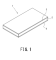
- FIG. 1 is a perspective view showing a coextruded sheet according to an embodiment.
- FIG. 2 is a sectional view showing the coextruded sheet shown in FIG. 1.
- FIG. 3 is a cross-sectional view showing the coextruded sheet after heating.
- FIG. 4 is a cross-sectional view showing the coextruded sheet after heating.
- FIG. 5 is a cross-sectional view showing a coextruded sheet including a decorative film.
- the coextruded sheet according to the present disclosure may include polycarbonate resin.
- the coextruded sheet may have a density of 0.4 to 0.9 g/cm 3 .
- the coextruded sheet may have a thickness of 1 to 5 mm and satisfy the following formula (1).
- t1 represents the thickness of the first skin layer
- t2 represents the thickness of the second skin layer
- T represents the thickness of the coextruded sheet.
- the coextruded sheet may include a bulge formed on the surface of the coextruded sheet by heating when heated in a 250° C. heating atmosphere for 30 minutes.
- the thickness t3 of the coextruded sheet including the bulges may be 1.5 times or less the average thickness t4 of the coextruded sheet before heating.
- the coextruded sheet after heating may have less than one bulge per 100 cm 2 of its surface.
- the coextruded sheet may include polycarbonate resin.
- a core layer made of a foamed resin, a first skin layer made of a non-foamed resin and laminated on one main surface of the core layer, and a second skin layer laminated on the other main surface of the core layer.
- the coextruded sheet may have a density of 0.4 to 0.9 g/cm 3 , a thickness of 1 to 5 mm, and satisfy the following formula (1). 0.10 ⁇ (t1+t2)/T ⁇ 0.5 (1)
- t1 represents the thickness of the first skin layer
- t2 represents the thickness of the second skin layer
- T represents the thickness of the coextruded sheet.
- the average thickness t5 of the coextruded sheet after heating may be 1.5 times or less than the average thickness t4 of the coextruded sheet before heating. .
- the density of the coextruded sheet and the thickness of the skin layer relative to the thickness of the coextruded sheet it is possible to suppress surface blisters and cracks that occur during heat forming such as vacuum forming. It is possible to obtain lightweight properties and mechanical strength. Furthermore, it is possible to suppress deterioration of the appearance and design of the coextruded sheet during heat forming such as vacuum forming.
- the coextruded sheet may include polycarbonate resin.
- a core layer made of a foamed resin, a first skin layer made of a non-foamed resin and laminated on one main surface of the core layer, and a second skin layer laminated on the other main surface of the core layer.
- the coextruded sheet may have a density of 0.4 to 0.9 g/cm 3 , a thickness of 1 to 5 mm, and satisfy the following formula (1). 0.10 ⁇ (t1+t2)/T ⁇ 0.5 (1)
- t1 represents the thickness of the first skin layer
- t2 represents the thickness of the second skin layer
- T represents the thickness of the coextruded sheet.
- the core layer may have a foaming ratio of 1.6 to 3.3 times. Thereby, it is possible to suppress deterioration of the appearance and design of the coextruded sheet during heat forming such as vacuum forming, and also to obtain superior lightness and mechanical strength.
- the polycarbonate resin contained in the first and second skin layers may have a melt volume rate of 1.0 to 5 times that of the polycarbonate resin contained in the core layer. Thereby, it is possible to suppress non-uniformity of the bubble size in the core layer.
- the polycarbonate resin contained in the first and second skin layers may have a melt volume rate of 1.5 to 3 times that of the polycarbonate resin contained in the core layer. Thereby, vacuum formability can be improved.
- the coextruded sheet may have a density of 0.82 g/cm 3 or less. Thereby, superior lightness and mechanical strength can be obtained.
- the coextruded sheet When the coextruded sheet is heated in a 200°C atmosphere for 30 minutes, the coextruded sheet has a dimensional change rate of -5 to 0% in either the extrusion direction or the width direction perpendicular to the extrusion direction in plan view. You may do so. This makes it possible to ensure the dimensional stability of the coextruded sheet during heat forming such as vacuum forming.
- the coextruded sheet may have a specific flexural modulus of 1.5 GPa ⁇ cm 3 /g or more. Thereby, the weight of the coextruded sheet can be reduced, and the mechanical strength can be improved.
- the coextruded sheet may have a specific flexural modulus of 2 GPa ⁇ cm 3 /g or more. This makes it possible to further reduce the weight and improve the mechanical strength of the coextruded sheet.
- the coextruded sheet may further include a decorative film.
- the decorative film may be laminated on the outer surface of at least one of the first skin layer and the second skin layer. Thereby, it is possible to give a design suitable for the purpose of the molded product obtained by vacuum forming the coextruded sheet.
- FIGS. 1 to 5 embodiments of the coextruded sheet 1 of the present disclosure will be specifically described using FIGS. 1 to 5.
- the same reference numerals are attached to the same or corresponding components in the figures, and the same explanations will not be repeated. Note that, in order to make the explanation easier to understand, in the drawings referred to below, the configuration is shown in a simplified or schematic manner, and some structural members are omitted.
- the coextruded sheet 1 is made of polycarbonate resin.
- the coextruded sheet 1 according to this embodiment has a sheet shape.
- the coextruded sheet 1 is manufactured by coextruding molten polycarbonate resin.
- the resin used in the present disclosure may be other engineering plastics as long as they include polycarbonate resin.
- Engineering plastics are thermoplastic resins that have a deflection temperature under load of 100°C or higher. Examples of engineering plastics include polycarbonate resin (PC), modified polyphenylene ether (m-PPE), and syndiotactic polystyrene (SPS).
- the resin used in the coextruded sheet 1 of the present disclosure can contain at least one selected from the group consisting of these engineering plastics.
- the resin material of the coextruded sheet 1 may be any engineering plastic that can be extruded. Further, an ultraviolet absorber, an anti-aging agent, etc. may be added to the resin material of the coextruded sheet 1.
- the coextruded sheet 1 has a density of 0.4-0.9 g/cm 3 .
- the density of the coextruded sheet 1 is 0.4 to 0.82 g/cm 3 . Thereby, superior lightness and mechanical strength can be obtained.
- the coextruded sheet 1 includes a core layer 2, a skin layer 3 laminated on one main surface of the core layer 2, and a skin layer 4 laminated on the other main surface of the core layer 2. It has As shown in FIG. 2, the coextruded sheet 1 has a thickness T of 1 to 5 mm.
- the core layer 2 is made of foamed resin.
- the core layer 2 can be formed by foam-molding molten polycarbonate resin. That is, the core layer 2 has many air bubbles.
- a large number of cells have a substantially elliptical shape extending in the extrusion direction in a cross-sectional view taken in the thickness direction in a direction along the extrusion direction during extrusion molding.
- the bubbles included near the center of the core layer 2 in the thickness direction have a larger bubble diameter than the bubbles 21 included near the ends of the core layer 2 in the thickness direction.
- the bubble diameter of the large number of bubbles 21 gradually becomes smaller from the center in the thickness direction of the core layer 2 toward the ends in the thickness direction.
- the skin layer 3 is made of non-foamed resin. That is, the skin layer 3 is not foam-molded.
- the skin layer 3 is extruded from the die outlet in an unfoamed state by a coextrusion method, and is laminated integrally with the core layer 2.
- the skin layer 3 has a thickness t1.
- a thermoplastic resin that can be well bonded to the core layer 2 may be used. More specifically, it is particularly preferable that the resin material of the skin layer 3 is the same resin material as the core layer 2. Further, the skin layer 3 can be made of a reinforced resin containing an inorganic filler in order to strengthen the skin layer 3. With these configurations of the skin layer 3, it is possible to reduce the weight and improve the strength while efficiently improving the strength. Examples of the inorganic filler include glass fiber, carbon fiber, aramid fiber, talc, and mica.
- the skin layer 4 has a thickness t2.
- the skin layer 4 is the same as the skin layer 3 except that it is laminated on the other main surface of the core layer 2. Therefore, a detailed explanation of the skin layer 4 will be omitted.
- the thickness t1 of the skin layer 3 and the thickness t2 of the skin layer 4 are measured as follows.
- a cross section of the coextruded sheet 1 cut in the thickness direction along the width direction is observed using a microscope.
- a KEYENCE model number VHX-60000 is used as a microscope.
- the magnification of the microscope may be such that the diameter of the bubbles at the interface between the skin layer 3 and the core layer 2 of the coextruded sheet 1 can be confirmed.
- 15 are the air bubbles close to the surface of the co-extruded sheet 1 on each virtual boundary line when the cross-section of the co-extruded sheet 1 is divided into 16 equal parts in the width direction. Among them, the bubble closest to the surface of the coextruded sheet 1 is confirmed.
- the boundary between the core layer 2 and the skin layer 4 was similarly defined, and the thickness t1 of the skin layer 3 and the thickness t2 of the skin layer 4 were measured.
- the thickness t1 of the skin layer 3 and the thickness t2 of the skin layer 4 are each preferably 0.050 mm or more from the viewpoint of making the thickness T of the coextruded sheet 1 as uniform as possible during coextrusion molding.
- the total thickness of the skin layer which is the sum of the thickness t1 of the skin layer 3 and the thickness t2 of the skin layer 4, is preferably 0.10 to 0.5 with respect to the thickness T of the coextruded sheet 1. That is, the coextruded sheet 1 satisfies the following formula (1). 0.10 ⁇ (t1+t2)/T ⁇ 0.5 (1) If the thickness (t1+t2) of the entire skin layer is less than 0.10 with respect to the thickness T of the coextruded sheet 1, it will be difficult to obtain the mechanical strength reinforcing effect by the non-foamed resin of the skin layer, and the specific flexural modulus etc. mechanical strength decreases.
- the thickness (t1+t2) of the entire skin layer becomes larger than 0.5 with respect to the thickness T of the coextruded sheet 1, the density of the coextruded sheet 1 increases. As a result, the coextruded sheet 1 loses its lightweight properties due to foaming.
- the ratio of the thickness of the entire skin layer (t1+t2) to the thickness T of the coextruded sheet 1 is preferably in the range of 0.15 to 0.45, more preferably in the range of 0.2 to 0.4. It is better. By setting the ratio of the thickness (t1+t2) of the entire skin layer to the thickness T of the coextruded sheet 1 within this range, the specific flexural modulus can be improved while reducing the weight by reducing the density.
- the thickness of the entire skin layer (t1+t2) to the thickness T of the coextruded sheet 1 in the range of 0.2 to 0.4, the thickness of the core layer 2 to make the bubble unevenness uniform is ensured. While achieving this, it is possible to improve secondary processability such as vacuum forming.
- the surface that occurs during heat forming such as vacuum forming can be reduced. Blistering and cracking can be suppressed, and excellent lightness and mechanical strength can be obtained.
- the melt volume rate (hereinafter referred to as MVR) of the polycarbonate resin contained in the skin layer 3 is the same as the MVR of the polycarbonate resin contained in the core layer 2, or higher than the MVR of the polycarbonate resin contained in the core layer 2. .
- the MVR of the polycarbonate resin contained in the skin layer 3 is 1.0 to 5 times, preferably 1.5 to 3 times, the MVR of the polycarbonate resin contained in the core layer 2. .
- the resin By making the MVR of the resin contained in the skin layer 3 the same as the MVR of the resin contained in the core layer 2 or higher than the MVR of the resin contained in the core layer 2, the resin can be discharged from the die outlet during extrusion molding. Immediately after the skin layer 3 is formed, the temperature of the resin forming the skin layer 3 can be lowered as much as possible. As a result, the viscosity of the skin layer 3 immediately after being discharged from the die outlet can be reduced, thereby suppressing swelling or tearing of the surface of the skin layer 3 caused by non-uniformity in the size of bubbles contained in the core layer 2. be able to.
- the MVR ratio of the resin contained in the skin layer 3 is smaller than 1.0 times, it becomes difficult to lower the resin temperature, and it becomes difficult to suppress the swelling or tearing of the surface of the skin layer 3. Furthermore, when the MVR ratio of the resin contained in the skin layer 3 is 1.5 times or more, it becomes easier to suppress non-uniformity of the bubble size in the core layer 2 during extrusion molding, and the preheating during vacuum molding becomes easier. You can save time and improve productivity. On the other hand, if the MVR ratio of the resin contained in the skin layer 3 is larger than 5 times, when trying to properly flow the resin forming the skin layer 3 in the die during extrusion molding, the resin forming the core layer 2 It is necessary to extremely lower MVR.
- the MVR ratio of the resin contained in the skin layer 3 is 3 times or less, the bubble spots in the core layer 2 of the coextruded sheet 1 tend to become uniform, and the coextruded sheet 1 is easily processed in secondary processing such as vacuum forming. can be improved. Therefore, consideration must be given to ensuring appropriate fluidity of the resin forming the core layer 2 and skin layer 3 during extrusion molding, and controlling the viscosity to suppress swelling or tearing of the surface of the skin layer 3.
- the MVR of the polycarbonate resin contained in the skin layer 3 is 1.0 to 5 times, preferably 1.5 to 3 times, the MVR of the polycarbonate resin contained in the core layer 2. Good. This also applies to the skin layer 4 and the core layer 2.
- the MVR of the resin contained in the skin layer 3 and the core layer 2 is measured by a plastic flow characteristic test (based on JISK7199 and ISO11443) using a capillary rheometer and a slit die rheometer.
- the length of the capillary die is 5 mm
- the inner diameter is 1 mm
- the measurement temperature is 300°C.
- the core layer 2 of the present disclosure is preferably foam-molded using a physical foaming agent such as nitrogen or carbon dioxide, which has a relatively low pressure. is more preferable.
- a physical foaming agent such as nitrogen or carbon dioxide
- the pressure of the physical blowing agent can be set at a relatively low level of 1 to 6 MPa, and a large number of fine bubbles can be formed. Thereby, it is possible to more reliably suppress bulges and the like when heated at high temperatures during vacuum forming.
- the average cell diameter of the bubbles is preferably 0.1 mm or more, and 1.0 mm or less, preferably 0.3 mm or less.
- the foaming ratio of the core layer 2 is preferably 1.6 or more and 3.3 times or less.
- the foaming ratio of the core layer 2 is preferably 3.1 times or less. Thereby, even better lightness and mechanical strength can be obtained.
- the coextruded sheet 1 is formed into various shapes by vacuum forming.
- vacuum forming the coextruded sheet 1 is usually heated to about 200° C. to begin drawdown, and then applied to a mold or the like and vacuum-suctioned to form the sheet. That is, it is preferable that the amount of deformation (rate of dimensional change before and after heating) of the coextruded sheet 1 is small with respect to the heating temperature during vacuum forming.
- the coextruded sheet 1 has a dimensional change rate of -5% to 0% in the extrusion direction when the coextruded sheet is heated in an atmosphere of 200° C. for 30 minutes. Further, the coextruded sheet 1 has a dimensional change rate of -5 to 0% in the width direction.
- the coextruded sheet 1 has a dimensional change rate of -5 to 0% in either the extrusion direction or the width direction.
- the coextruded sheet 1 has a dimensional change rate of -5 to 0% in both the extrusion direction and the width direction.
- the width direction is a direction perpendicular to the above-mentioned extrusion direction in plan view. Thereby, the coextruded sheet 1 has excellent dimensional stability before and after heating.
- the dimensional change rate in the extrusion direction can be calculated using the following formula.
- Dimensional change rate in the extrusion direction (%) ⁇ (distance between gauge lines in the extrusion direction after heating - distance between gauge lines in the extrusion direction before heating) / distance between gauge lines in the extrusion direction before heating ⁇ x 100
- the dimensional change rate in the width direction can be calculated according to the following formula.
- Dimensional change rate in the width direction (%) ⁇ (distance between gauge lines in the width direction after heating - distance between gauge lines in the width direction before heating/distance between gauge lines in the width direction before heating) ⁇ x 100
- the coextruded sheet 1 has a specific flexural modulus of 1.5 GPa cm 3 /g or more.
- the specific flexural modulus is the value obtained by dividing the flexural modulus of the coextruded sheet 1 by the density of the coextruded sheet 1. be. That is, it can be said that the larger the specific flexural modulus, the more excellent the lightness and mechanical strength.
- the bending elastic modulus is measured by a three-point bending test (according to ISO178 or JIS7171). At this time, the flexural modulus is measured in the atmosphere. The test speed is 10 mm/min.
- the coextruded sheet 1 is heat-shaped into a desired shape mainly by vacuum forming or the like.
- bulges may occur on the sheet surface, which may deteriorate the appearance and design of the sheet surface. Therefore, it is preferable to suppress the occurrence of bulges in the coextruded sheet 1.
- FIG. 3 when the coextruded sheet 1 is heated for 30 minutes in a 250°C heating atmosphere, the average thickness t5 of the coextruded sheet 1 after heating is relative to the average thickness t4 of the coextruded sheet before heating. It is 1.5 times or less.
- S shown by a broken line in FIG. 3 is the surface of the coextruded sheet 1 before heating.
- the coextruded sheet 1 can suppress the generation of bulges due to heating, and can reduce changes in thickness by comparing before and after heating. Thereby, the coextruded sheet 1 can improve its appearance and design during heat forming such as vacuum forming.
- the thickness t3 of the coextruded sheet including the above-described bulged portion 11 is 1.5 times or less of the average thickness t4 of the coextruded sheet before heating shown in FIG.
- the coextruded sheet 1 after heating has less than one bulge 11 per 100 cm 2 of its surface. That is, according to the coextruded sheet 1, the height of the bulges 11 generated on the surface due to heating can be reduced, and the number of bulges 11 generated can be suppressed. Thereby, the coextruded sheet 1 can improve its appearance and design during heat forming such as vacuum forming.
- Heat-formed coextruded sheets are used in applications that require particularly good appearance design, such as containers such as signboards and suitcases, and interior and exterior materials for automobiles and other vehicles. Therefore, defects such as blistering in heat excipients are undesirable for the listed applications. Therefore, it is preferable that the swelling of the coextruded sheet 1 during heating is suppressed as much as possible, and specifically, the number of bulged portions 11 should be less than one.
- the coextruded sheet 1 may contain a large number of scaly fillers.
- the scaly filler is, for example, an inorganic filler such as talc, calcium carbonate, mica, clay, boron nitride, clastonite, potassium titanate, or glass flakes.
- the scale-like filler may be surface-treated with a silane coupling agent, a titanate coupling agent, a phosphate coupling agent, a fatty acid coupling agent, or the like.
- the scaly filler has an aspect ratio of 5 or more. The aspect ratio is calculated by dividing the average particle size of the scaly filler by the average thickness (average particle size/average thickness).
- the aspect ratio of the scaly filler is preferably 10 or more, more preferably 30 or more.
- the aspect ratio of the scaly filler is preferably less than 50.
- the specific surface area of the scaly filler is preferably 5 to 20 m 2 /g. If the specific surface area of the scaly filler becomes too small, surface smoothness will be difficult to develop due to the scaly filler sliding on the surface, and if the specific surface area becomes too large, the resistance of the scaly filler in the molten resin will increase. As a result, it becomes difficult to orient the scaly filler appropriately.
- the core layer 2 may include a scale-like filler oriented substantially parallel to the interface between the core layer 2 and the skin layer 3 in a region near the boundary with the skin layer 3.
- the neighboring region is a region positioned in the thickness direction of the core layer 2 in a range from the interface between the core layer 2 and the skin layer 3 to a thickness of 5% of the core layer thickness.
- the bubbles contained in the core layer 2 have a shape extending along the extrusion direction during extrusion molding.
- the scale-like filler is also oriented substantially parallel to the cell walls of the cells extending in the stretching direction, so that the strength of the cell walls can be improved. As a result, tearing of the coextruded sheet 1 along the extrusion direction can be suppressed.
- the scale-like filler when the scale-like filler is approximately parallel, it means that the scale-like filler is located at the boundary between the core layer 2 and the skin layer 3 in a cross section of the coextruded sheet 1 cut in the thickness direction in the direction along the extrusion direction during extrusion molding. It means having an inclination of 0° or more and less than 5° with respect to the plane. In other words, it refers to a state in which the surface (principal surface) of the scale-like filler and the boundary surface between the core layer 2 and the skin layer 3 are opposed to each other so as to be substantially parallel to each other. The same applies to the scale-like filler oriented in the core layer 2 near the boundary between the core layer 2 and the skin layer 4.
- the orientation state of a large number of scale-like fillers included in the region near the boundary between the core layer 2 and the skin layer 3 was calculated as follows. First, in a cross section in the thickness direction along the extrusion direction during extrusion molding, 50 electron micrographs of 150 x 150 ⁇ m were taken at equal intervals from the tip to the rear end in the extrusion direction in the neighboring region, and at the center in the thickness direction of the neighboring region. Take a photo. Among all the scaly fillers included in these 50 electron micrographs, the scaly fillers oriented substantially parallel to the interface between the core layer 2 and the skin layer 3 are confirmed. Thereby, the proportion of the scale-like fillers oriented substantially in parallel among the large number of scale-like fillers included in the neighboring region is calculated.
- the core layer 2 may include a scale-like filler oriented at an angle of 5° to 90° with respect to the surface of the coextruded sheet 1 in the central region of the core layer 2 in the thickness direction.
- the central region refers to a region having a thickness of 25% from the center in the thickness direction toward the interface between the core layer 2 and the skin layer 3, assuming that the thickness of the core layer 2 is 100%. It is preferable that 40% or more of the scale-like fillers included in the central region are oriented at an angle of 5° to 90° with respect to the surface S of the coextruded sheet 1. Thereby, the moldability of the coextruded sheet 1 can be improved.
- the moldability of the coextruded sheet 1 can be further improved.
- the bubbles contained in the central region of the core layer 2 tend to become larger during extrusion molding compared to the above-mentioned neighboring region. This is because the central region is less likely to be cooled after extrusion than the neighboring regions. If the bubbles become too large, they may cause damage to the coextruded sheet 1.
- by tilting the scale-like filler in the central region and arranging it randomly between the bubbles it is possible to suppress the growth of the bubbles in all directions.
- the strength of the coextruded sheet 1 or the strength during molding, that is, the moldability can be improved.
- a foamed resin molded product is produced by vacuum forming the coextruded sheet 1 as a material, it is possible to suppress the bubbles contained in the coextruded sheet 1 from bursting or the coextruded sheet 1 from being damaged.
- the orientation state of the large number of scale-like fillers included in the central region of the core layer 2 can be calculated as follows. First, as in the case of the neighboring region, 50 microscopic photographs are taken at equal intervals at the center of the core layer 2 in the thickness direction. Among all the scale-like fillers included in these 50 electron micrographs, scale-like fillers oriented at an angle of 5° to 90° with respect to the surface of the coextruded sheet 1 are confirmed. Accordingly, the proportion of the scale-like fillers that are oriented at an angle of 5° to 90° with respect to the surface of the coextruded sheet 1 among the large number of scale-like fillers included in the central region is calculated.
- resin pellets as a resin material are charged into the screw cylinder of the main extruder.
- the resin material is polycarbonate resin.
- the resin pellets are heated in a screw cylinder to produce molten resin.
- a blowing agent is injected into the molten resin from a blowing agent injection cylinder attached to the screw cylinder of the main extruder.
- the blowing agent is dissolved in the molten resin by the above-mentioned screw cylinder and kneaded to be uniformly dispersed. In this way, a mixed molten resin is produced.
- the mixed molten resin is discharged from the die outlet to form the core layer 2 .
- resin pellets serving as a resin material are placed in each of the screw cylinders of the two sub-extruders, and are heated and melted to produce two molten resins.
- One of the two molten resins is discharged from the die outlet to form the skin layer 3, and the other is discharged from the die outlet to form the skin layer 4.
- the mixed molten resin and the two molten resins are combined in a die from each extruder, and a skin layer 3 is laminated on one of the main surfaces of the core layer 2, and a skin layer 4 is laminated on the other main surface of the core layer 2. are discharged from the die outlet so that they are stacked.
- the mixed molten resin foams when it is extruded from the die outlet into the atmosphere.
- the coextruded sheet 1 is manufactured.
- the foaming method is a physical foaming method using an inert gas such as nitrogen and carbon dioxide gas as a foaming agent.
- the coextruded sheet 1 thus extruded is conveyed to a cutting machine by a take-up machine.
- the cutting machine cuts the coextruded sheet 1 into a desired shape.
- the coextruded sheet 1 produced in this way can be used in the following applications by shaping it into a desired shape by vacuum forming or the like.
- products and parts that require relatively high strength such as signboards or mobility materials such as automobile exterior materials, products and parts that require heat resistance such as batteries or trays for heat generating parts used in manufacturing processes that involve heating processes.
- products and parts that require weight reduction The coextrusion sheet 1 contains a polycarbonate resin and is foam-molded by a coextrusion method, so that it is suitable as a material for molding these products and parts.
- the coextruded sheet 1 may have a decorative film 5, as shown in FIG.
- the decorative film 5 is laminated on the outer surface of at least one of the skin layer 3 and the skin layer 4.
- the outer surface of the skin layer 3 is the surface of the skin layer 3 opposite to the surface facing the core layer 2.
- the decorative film 5 include, but are not limited to, colored films, films with arbitrary patterns printed on the surface, films with patterns such as grain, wood grain, stone grain, or carbon-like patterns.
- the material of the decorative film 5 is, for example, PC, PMMA, PC/PMMA alloy, ABS, AES, vinyl chloride, copolymerized PET, or the like.
- the coextruded sheet 1 may be composed of three layers: a core layer 2, and skin layers 3 and 4, and may be composed of five decorative films laminated on at least one of the skin layers 3 and 4. It's okay.
- the coextruded sheet 1 can contribute to improving resource utilization efficiency, reducing transportation burden, reducing energy consumption, and reducing CO 2 emissions.
- Goal 7 Affordable and Clean Energy
- Goal 9 Industry and Technology
- SDGs 17 Sustainable Development Goals
- test pieces of Examples 1 to 10 and Comparative Examples 1 to 6 were prepared, and the specific flexural modulus, presence or absence of fracture in the Charpy impact test, and swelling of the test pieces when heated at 250°C for 30 minutes were determined.
- the resin material used for these test pieces is polycarbonate resin. Note that the present disclosure is not limited to these examples.
- Example 1 The test piece of Example 1 was produced as follows using a coextrusion molding method. First, polycarbonate resin was charged into the screw cylinder of the main extruder, and was shear-kneaded while heating at 270°C. Then, the blowing agent N2 was injected under a pressure of 4 MPa. A core layer was obtained by heating and melting the polycarbonate resin and the blowing agent at 215°C, and setting the temperature at the exit of the die to 215°C. At the same time, polycarbonate resin was charged into the screw cylinder of the sub-extruder, and was shear kneaded while heating at 255°C, and the exit temperature of the die was set at 215°C to obtain two skin layers.
- Example 1 a test piece of Example 1 was obtained in which skin layers made of non-foamed resin were laminated on both main surfaces of the core layer made of foamed resin.
- the exit gap of the die was set so that the thickness T of the test piece of Example 1 had the value shown in Table 1, and the test piece of Example 1 was coextruded at a drawing speed of 0.7 m/min.
- Examples 2 to 10 The test pieces of Examples 2 to 10 were tested in the same manner as in Example 1, except that the exit gap of the die, the discharge flow rate of the main extruder and the sub-extruder, and the take-up speed were set so that each thickness T became the value shown in Table 1. It was prepared in the same manner as the test piece of Example 1. That is, the test pieces of Examples 1 to 10 have different thicknesses.
- Comparative example 1 The test piece of Comparative Example 1 was produced as follows using a coextrusion molding method. First, polycarbonate resin was charged into the screw cylinder of the main extruder, and was shear-kneaded while heating at 270°C. Thereafter, isopentane gas as a blowing agent was injected so that the content was 0.53 mol/kg resin. A core layer was obtained by heating and melting the polycarbonate resin and the blowing agent at 215°C, and setting the temperature at the exit of the die to 215°C.
- Comparative example 2 The test piece of Comparative Example 2 was produced as follows using an extrusion lamination method. First, polycarbonate resin was charged into the screw cylinder of the main extruder, and was shear-kneaded while heating at 270°C. Thereafter, isopentane gas as a blowing agent was injected so that the content was 0.53 mol per 1 kg of the polycarbonate resin introduced. A core layer was obtained by heating and melting the polycarbonate resin and the blowing agent at 200°C, and setting the temperature at the exit of the die to 200°C. The exit gap of the die was set so that the thickness T of the test piece of Comparative Example 2 had the value shown in Table 1, and the core layer was extruded at a drawing speed of 6.5 m/min. Next, while the discharged core layer was in a molten state, two skin layers made of polycarbonate resin prepared in advance were bonded and laminated on both main surfaces of the core layer.
- Comparative example 3 The test piece of Comparative Example 3 was produced by laminating a core layer and a skin layer by thermocompression bonding. First, a core layer was obtained in the same manner as the test piece of Comparative Example 2. Next, two skin layers made of polycarbonate resin prepared in advance were laminated by hot pressing on both main surfaces of the cooled and solidified core layer.
- Comparative example 4 The test piece of Comparative Example 4 was created by injection molding. Polycarbonate resin was put into a screw cylinder of an injection molding machine, and shear kneaded while heating at 270°C. Thereafter, nitrogen as a foaming agent was injected under a pressure of 8 MPa, and the mold was filled with the polycarbonate resin injected with the foaming agent. Thereafter, the pressure in the mold was released using the core-back method to obtain a test piece. The mold was designed so that the thickness of the test piece was 3 mm.
- the density of the test piece shown in Table 1 was calculated as follows. A sheet-like test piece was cut out with a dimension of 400 mm in the extrusion direction. After dividing the cross section of the test piece in the width direction into 11 equal parts in the width direction, the thickness was measured at 10 points at equal intervals excluding the ends, and the arithmetic mean value of these thicknesses was taken as the average thickness of the test piece. The length of each side of the test piece in the width direction and extrusion direction was measured using a tape measure, and the volume of the test piece was calculated from the length of each side and the average thickness. In addition, the weight of the test piece was measured using an electronic balance, and the density of the test piece was determined by dividing the weight of the test piece by the volume.
- the dimensional change rate shown in Table 1 was calculated as follows. First, a sample piece with dimensions of 120 mm x 120 mm was obtained from a sheet-like test piece. At this time, sample pieces were taken from the center and both ends of the entire width of the test piece. The center part is a part located at 1/2 of the length of the full width of the test piece, and both end parts are parts 50 mm apart from the extreme end of the full width of the test piece. Marks were placed on each sample piece in the extrusion direction and width direction, and furthermore, a mark was placed in the center of each sample piece for measuring the distance between gauge lines in the extrusion direction and width direction.
- the distance between the gauge lines in the extrusion direction and the width direction was measured using a scale ruler or metal ruler capable of measuring the distance to a minimum of 0.5 mm. Thereafter, a metal container with a PTFE (polytetrafluoroethylene) sheet spread on the inner bottom was placed in a dryer, and the temperature of the dryer was adjusted so that the temperature of the metal container was 200 ⁇ 2°C. The sample piece was placed in a metal container and heated for 30 minutes. After the heat treatment was completed, the sample piece was taken out from the metal container and cooled to room temperature, and then the distance between the gauge lines in the extrusion direction and width direction was measured. Then, the dimensional change rate was calculated using the above-mentioned formula.
- the absolute value of the dimensional change rate in the extrusion direction was larger than the dimensional change rate in the width direction, so Table 1 shows the dimensional change rate in the extrusion direction. That is, the dimensional change rate in the width direction is smaller than the dimensional change rate in the extrusion direction. Therefore, the dimension in the width direction was more stable than in the extrusion direction before and after heating.
- the thickness T and specific flexural modulus of the test pieces shown in Table 1 were measured according to the measurement method described above. Further, the MVR ratio shown in Table 1 is the MVR ratio of the polycarbonate resin contained in the skin layer to the polycarbonate resin contained in the core layer, and was measured by the above-mentioned measuring method.
- sheet bulge/bulge indicates the surface bulge after heating of each sheet-like test piece.
- the surface bulge is the above-mentioned bulge.
- the presence or absence of sheet swelling after heating at a temperature of 250° C. for 30 minutes was evaluated. The specific method will be described below. Calculate the average thickness of the test piece before heating. Observe the cross section of the test piece using a micrometer, divide the cross section of the test piece into 11 equal parts in the width direction, measure the thickness at 10 equally spaced points excluding the edges, and calculate the arithmetic mean value of these thicknesses. The average thickness was used. The average thickness of the test piece after heating was calculated in the same manner as the test piece before heating.
- the test piece after heating was visually checked to determine the presence or absence of a bulge when compared with the surface of the test piece before heating.
- the bulge was visually confirmed, the cross section including the bulge was observed using a microscope, and the thickness t3 (see FIG. 4) of the test piece including the bulge was measured.
- the average thickness t5 of the test piece after heating is greater than 1.5 times the average thickness t4 of the test piece before heating, and the thickness t3 of the test piece including the bulge is the average thickness of the test piece before heating.
- a sample piece was obtained by cutting a test piece into a size of 100 mm x 100 mm. At this time, sample pieces were taken from the center and both ends of the entire width of the test piece. The central portion is a portion located at 1/2 the length of the full width of the sheet, and both end portions are portions 50 mm apart from the extreme end of the full width of the sheet.
- a metal container whose inner bottom was covered with a PTFE (polytetrafluoroethylene) sheet was placed in an electric furnace, and the temperature of the electric furnace was adjusted so that the temperature of the metal container was 250 ⁇ 2°C.
- Each cut test piece was placed in a metal container and heated for 30 minutes. After the heat treatment was completed, the test piece was taken out from the metal container. After the test piece was cooled to room temperature, the condition of the surface of the test piece was visually confirmed.
- the thickness ratio ⁇ (t1+t2)/T ⁇ of the skin layer 3 and core layer 2 of the coextruded sheet was controlled to 0.20 to 0.40, and the density was controlled to 0.4 to 0.9 g/ cm3. Through this control, it was possible to improve the weight and mechanical strength.
- the ratio of "A" in Examples 1 to 10 was relatively high at 70% or more, and it was found that in Examples 1 to 10, "sheet blistering" could be relatively suppressed. Furthermore, it is believed that by reducing the "sheet bulge” to 1.5 times or less, the coextruded sheet can obtain an excellent appearance and design after vacuum forming. Note that in the above test, the test piece was heated at a temperature of 250°C, but it is thought that the evaluation results of "sheet bulge/bulging part" would be the same even if the test piece was heated at a temperature of 200°C.
- the thickness ratio is preferably 0.20 or more and 0.40 or less
- the density of the test piece (sheet) is preferably 0.6 g/cm 3 or more and 0.8 g/cm 3 or less
- MVR The magnification is preferably 1.7 times or more and 2.7 times or less. Note that in the above test, the test piece was heated at a temperature of 250°C, but it is thought that the evaluation results of "sheet bulge/bulging part" would be the same even if the test piece was heated at a temperature of 200°C.
- the test piece of Example 8 which had an expansion ratio of 1.57 times, had a lower specific flexural modulus than the other examples.
- the expansion ratio of Comparative Example 5 which was produced by the same coextrusion as in the Example, was 3.42 times, and the specific flexural modulus of Comparative Example 5 was 1.38, which was significantly lower.
- the test piece of Comparative Example 6 had a foaming ratio of 1.63 and a specific flexural modulus of 2.00, which gave relatively good results, the density was 0.96, so it was not lightweight. It was inferior.
- the expansion ratio of the coextruded sheet should be set to 1.6. It is thought that it is better to increase the amount by ⁇ 3.3 times.
- the specific flexural modulus was 1.75 GPa ⁇ cm 3 /g, which showed a slight tendency to decrease. Therefore, it is considered more preferable that the expansion ratio of the coextruded sheet is 1.6 to 3.1 times.
- Example 5 and Examples 8 to 10 have a density of 0.82 g/cm 3 or less.
- Example 9 comparatively good results were obtained with a specific flexural modulus of 2.00 GPa ⁇ cm 3 /g or more, whereas in Examples 8 and 10, where the density was 0.83 g/cm 3 or more, the ratio was lower.
- the flexural modulus decreased slightly.
- the density of the coextruded sheet is preferably 0.4 to 0.9 g/cm 3 , but it is preferable to set it to 0.82 g/cm 3 or less, that is, 0.4 to 0.82 g/cm 3 . , it was possible to obtain superior lightness and mechanical strength.
- Comparative Examples 1 to 3 are low-density polycarbonate laminated resin sheets using isopentane gas as a blowing agent.
- the density of the test pieces of Comparative Examples 1 to 3 was 0.1 to 0.11, which was less than 0.4. Furthermore, in the test pieces of Comparative Examples 1 to 3, the ratio of the skin layer thickness (t1+t2) to the test piece thickness T was less than 0.10.
- the foaming ratio of the test pieces is increased by using organic volatile isopentane gas as a blowing agent. Therefore, on the surface of the test piece after extrusion foam molding, unevenness due to the destruction of the bubbles becomes noticeable. In addition, since the shear rate during extrusion molding was relatively high, the test piece was largely stretched in the extrusion direction. As a result, the bubbles have a flat shape that is largely elongated in the extrusion direction. Due to these factors, when the test piece is heated in an atmosphere at or above the glass transition temperature of the polycarbonate resin, air bubbles within the test piece tend to shrink.
- the thickness of the skin layer (t1+t2) with respect to the thickness T of the test piece was taken into consideration, and the density of the test piece was further adjusted to 0.4 to 0.9 g. /cm 3 , it was possible to obtain excellent lightness and mechanical strength, and also to improve the appearance and design properties during heating under vacuum forming conditions.
- Comparative Example 4 is a sheet-like test piece produced using an injection molding method.
- a skin layer is formed on the surface of the test piece depending on the cooling rate distribution within the mold.
- the evaluation of "sheet bulge/bulge” was "C”
- the evaluation of "sheet bulge” and “bulge” was “B”. Since the resin that forms the skin layer of the test piece produced by injection molding contains a foaming agent, the foaming agent expands when heated, creating relatively large and numerous bulges on the surface of the test piece. It is thought that he did so. Therefore, molded articles produced by injection molding and coextruded sheets are differentiated.
- Comparative Example 5 the evaluation of "specific flexural modulus” and “sheet bulge/bulging part” is “C”, and the evaluation of “sheet bulging”, “bulging part” and “presence of fracture” is It was “B”. Furthermore, Comparative Example 6 was relatively excellent in mechanical strength and appearance design when heated under vacuum forming conditions. However, since the density of Comparative Example 6 was greater than 0.9 g/cm 3 , it was not possible to reduce the weight.
Landscapes
- Engineering & Computer Science (AREA)
- Mechanical Engineering (AREA)
- Laminated Bodies (AREA)
- Extrusion Moulding Of Plastics Or The Like (AREA)
Abstract
Description
0.10≦(t1+t2)/T≦0.5 ・・・(1)
式(1)中、t1は前記第1スキン層の厚みを示し、t2は前記第2スキン層の厚みを示し、Tは前記共押出シートの厚みを示す。
共押出シートは、250℃加熱雰囲気下で30分加熱したとき、加熱によって共押出シートの表面に生じる膨出部を含んでよい。膨出部を含む共押出シートの厚みt3は、加熱前の共押出シートの平均厚みt4に対して1.5倍以下であってよい。加熱後の共押出シートは、その表面100cm2あたりに1つ未満の前記膨出部を有してよい。
0.10≦(t1+t2)/T≦0.5 ・・・(1)
式(1)中、t1は前記第1スキン層の厚みを示し、t2は前記第2スキン層の厚みを示し、Tは前記共押出シートの厚みを示す。
共押出シートを250℃加熱雰囲気下で30分加熱したとき、加熱後の共押出シートの平均厚みt5は、加熱前の共押出シートの平均厚みt4に対して1.5倍以下であってよい。
0.10≦(t1+t2)/T≦0.5 ・・・(1)
式(1)中、t1は前記第1スキン層の厚みを示し、t2は前記第2スキン層の厚みを示し、Tは前記共押出シートの厚みを示す。
コア層は、1.6~3.3倍の発泡倍率を有してよい。
0.10≦(t1+t2)/T≦0.5 ・・・(1)
式(1)中、t1は第1スキン層の厚みを示し、t2は第2スキン層の厚みを示し、Tは共押出シートの厚みを示す。
共押出シートは、250℃加熱雰囲気下で30分加熱したとき、加熱によって共押出シートの表面に生じる膨出部を含んでよい。膨出部を含む共押出シートの厚みt3は、加熱前の共押出シートの平均厚みt4に対して1.5倍以下であってよい。加熱後の共押出シートは、その表面100cm2あたりに1つ未満の膨出部を有してよい。
0.10≦(t1+t2)/T≦0.5 ・・・(1)
式(1)中、t1は前記第1スキン層の厚みを示し、t2は前記第2スキン層の厚みを示し、Tは前記共押出シートの厚みを示す。
共押出シートを250℃加熱雰囲気下で30分加熱したとき、加熱後の共押出シートの平均厚みt5は、加熱前の共押出シートの平均厚みt4に対して1.5倍以下であってよい。これにより、共押出シートの密度と共押出シートの厚みに対するスキン層の厚みとを制御したことにより、真空成形等の熱賦形時に生じる表面の膨れや割れを抑制することができ、かつ、優れた軽量性及び機械強度を得ることができる。さらに、真空成形等の熱賦形時における共押出シートの外観意匠性の悪化を抑制することができる。
0.10≦(t1+t2)/T≦0.5 ・・・(1)
式(1)中、t1は前記第1スキン層の厚みを示し、t2は前記第2スキン層の厚みを示し、Tは前記共押出シートの厚みを示す。
コア層は、1.6~3.3倍の発泡倍率を有してよい。これにより、真空成形等の熱賦形時における共押出シートの外観意匠性の悪化を抑制することができるとともに、より優れた軽量性及び機械強度を得ることができる。
0.10≦(t1+t2)/T≦0.5 ・・・(1)
スキン層全体の厚み(t1+t2)が共押出シート1の厚みTに対して0.10未満になると、スキン層の非発泡樹脂による機械強度の補強効果が得られにくく、比曲げ弾性率等の機械強度が低下する。一方、スキン層全体の厚み(t1+t2)が共押出シート1の厚みTに対して0.5よりも大きくなると、共押出シート1の密度が大きくなる。その結果、共押出シート1は、発泡による軽量性を損なうことになる。共押出シート1の厚みTに対するスキン層全体の厚み(t1+t2)の比は、好ましくは0.15~0.45の範囲がよく、より好ましくは0.2~0.4の範囲とするのがよい。共押出シート1の厚みTに対するスキン層全体の厚み(t1+t2)の比をこの範囲にすることで、密度低減による軽量化を図りながら比曲げ弾性率を向上させることが出来る。また、共押出シート1の厚みTに対するスキン層全体の厚み(t1+t2)の比を0.2~0.4の範囲にすることで、気泡斑を均一にするコア層2の厚みの担保を図りながら、真空成形等の二次加工性を向上させることができる。
押出方向の寸法変化率(%)={(加熱後の押出方向の標線間距離-加熱前の押出方向の標線間距離)/加熱前の押出方向の標線間距離}×100
一方、幅方向の寸法変化率は、以下の式の通り算出できる。
幅方向の寸法変化率(%)={(加熱後の幅方向の標線間距離-加熱前の幅方向の標線間距離/加熱前の幅方向の標線間距離)}×100
下記表1に示す通り、実施例1~10及び比較例1~6の試験片を作製し、比曲げ弾性率及びシャルピー衝撃試験での破壊有無、250℃30分加熱時における試験片の膨れを評価する試験を行った。これら試験片に用いられる樹脂材料は各々、ポリカーボネート樹脂である。なお、本開示は、これら実施例に限られるものではない。

実施例1の試験片は、共押出成形法を用いて次のように作製した。まず、主押出機のスクリュシリンダにポリカーボネート樹脂を投入し、270℃で加熱しながらせん断混錬された。その後、発泡剤のN2を4MPaの圧力下で注入した。ポリカーボネート樹脂と発泡剤とを215℃で加熱溶融させ、ダイス出口の温度を215℃としてコア層を得た。同時に、副押出機のスクリュシリンダにポリカーボネート樹脂を投入し、255℃で加熱しながらせん断混錬させ、ダイスの出口温度を215℃として2つのスキン層を得た。これらコア層とスキン層とをダイス内で合流させて積層化し、ダイスの出口から吐出させた。このようにして、発泡樹脂からなるコア層の両方の主面に非発泡樹脂からなるスキン層を積層させた実施例1の試験片を得た。なお、実施例1の試験片の厚みTが表1に示す値となるようにダイスの出口ギャップを設定し、引出速度を0.7m/分として実施例1の試験片を共押出成形した。
実施例2~10の試験片は、各々の厚みTが表1に示す値となるようにダイスの出口ギャップと主押出機、副押出機の吐出流量、引き取り速度を設定したこと以外は、実施例1の試験片と同様の方法で作成した。すなわち、実施例1~10の試験片は、各々の厚みが異なる。
比較例1の試験片は、共押出成形法を用いて次のように作製した。まず、主押出機のスクリュシリンダにポリカーボネート樹脂を投入し、270℃で加熱しながらせん断混錬された。その後、含有量が0.53mol/kg樹脂となるように発泡剤のイソペンタンガスを注入した。ポリカーボネート樹脂と発泡剤とを215℃で加熱溶融させ、ダイス出口の温度を215℃としてコア層を得た。同時に、2つの副押出機の各々のスクリュシリンダにポリカーボネート樹脂を投入し、255℃で加熱しながらせん断混錬させ、ダイスの出口温度を215℃として2つのスキン層を得た。これらコア層とスキン層とをダイス内で合流させて積層化し、ダイスの出口から吐出させた。このようにして、発泡樹脂からなるコア層の両方の主面に非発泡樹脂からなるスキン層を積層させた比較例1の試験片を得た。なお、比較例1の試験片の厚みTが表1に示す値となるようにダイスの出口ギャップを設定し、引出速度を6.5m/分として比較例1の試験片を共押出成形した。
比較例2の試験片は、押出ラミネート法を用いて次のように作製した。まず、主押出機のスクリュシリンダにポリカーボネート樹脂を投入し、270℃で加熱しながらせん断混錬された。その後、投入されたポリカーボネート樹脂1kgに対して含有量が0.53molとなるように発泡剤のイソペンタンガスを注入した。ポリカーボネート樹脂と発泡剤とを200℃で加熱溶融させ、ダイス出口の温度を200℃としてコア層を得た。比較例2の試験片の厚みTが表1に示す値となるようにダイスの出口ギャップを設定し、引出速度を6.5m/minとしてコア層を押出成形した。次に、吐出されたコア層が溶融している状態で、予め作製したポリカーボネート樹脂からなる2つのスキン層を各々コア層の両方の主面に貼り合わせて積層した。
比較例3の試験片は、コア層とスキン層とを熱圧着により積層して作製した。まず、比較例2の試験片と同様に、コア層を得た。次に、冷却固化したコア層の両方の主面に、予め作製したポリカーボネート樹脂からなる2つのスキン層を各々熱プレスして積層させた。
比較例4の試験片は、射出成形法によって作成した。射出成形機のスクリュシリンダにポリカーボネート樹脂を投入し、270℃で加熱しながらせん断混錬した。その後、発泡剤の窒素を8MPa圧力下で注入し、発泡剤が注入されたポリカーボネート樹脂を金型内に充填させた。その後、コアバック法を用いて金型の圧力を解放し試験片を得た。尚、試験片の厚みは3mmとなるように金型を設計した。
共押出シートの厚みTに対するスキン層全体の厚み(t1+t2)の比率に関して、実施例1~10において、厚み比率{(t1+t2)/T}が0.10~0.5である場合には、「比曲げ弾性率」、「シート膨れ/膨出部」及び「破壊の有無」のいずれにおいても「B」以上の評価を得ることができ、「膨出部」においては「A」の評価を得ることができた。特に、厚み比率が0.20~0.40であり、且つ、試験片の密度が0.4~0.9g/cm3である場合は、「比曲げ弾性率」及び「破壊の有無」において評価「A」を得た。すなわち、共押出シートのスキン層3とコア層2の厚み比率{(t1+t2)/T}を0.20~0.40に制御し、密度を0.4~0.9g/cm3に制御することにより、軽量性且つ機械強度の向上を図ることができた。「シート膨れ」の評価に関しては、実施例1~10において「A」の比率が7割以上と比較的多く、実施例1~10では「シート膨れ」を比較的抑制できることが分かった。また、「シート膨れ」を1.5倍以下にすることにより、共押出シートは、真空成形後の優れた外観意匠性を得ることができると考えられる。なお、上記試験では試験片を250℃の温度で加熱したが、試験片を200℃の温度で加熱しても「シート膨れ/膨出部」の評価結果は同様であると考えられる。
Claims (10)
- ポリカーボネート樹脂を含む共押出シートであって、
発泡樹脂からなるコア層と、
非発泡樹脂からなり、前記コア層の一方の主面に積層された第1スキン層と、
前記コア層の他方の主面の積層された第2スキン層とを備え、
前記共押出シートは、0.4~0.9g/cm3の密度を有し、
前記共押出シートは、1~5mmの厚みを有し、かつ、下記式(1)を満たし、
0.10≦(t1+t2)/T≦0.5 ・・・(1)
式(1)中、t1は前記第1スキン層の厚みを示し、t2は前記第2スキン層の厚みを示し、Tは前記共押出シートの厚みを示す。
前記共押出シートは、250℃加熱雰囲気下で30分加熱したとき、前記加熱によって前記共押出シートの表面に生じる膨出部を含み、
前記膨出部を含む前記共押出シートの厚みt3は、前記加熱前の共押出シートの平均厚みt4に対して1.5倍以下であり、
前記加熱後の共押出シートは、その表面100cm2あたりに1つ未満の前記膨出部を有する、共押出シート。 - ポリカーボネート樹脂を含む共押出シートであって、
発泡樹脂からなるコア層と、
非発泡樹脂からなり、前記コア層の一方の主面に積層された第1スキン層と、
前記コア層の他方の主面の積層された第2スキン層とを備え、
前記共押出シートは、0.4~0.9g/cm3の密度を有し、
前記共押出シートは、1~5mmの厚みを有し、かつ、下記式(1)を満たし、
0.10≦(t1+t2)/T≦0.5 ・・・(1)
式(1)中、t1は前記第1スキン層の厚みを示し、t2は前記第2スキン層の厚みを示し、Tは前記共押出シートの厚みを示す。
前記共押出シートを250℃加熱雰囲気下で30分加熱したとき、前記加熱後の共押出シートの平均厚みt5は、前記加熱前の共押出シートの平均厚みt4に対して1.5倍以下である、共押出シート。 - ポリカーボネート樹脂を含む共押出シートであって、
発泡樹脂からなるコア層と、
非発泡樹脂からなり、前記コア層の一方の主面に積層された第1スキン層と、
前記コア層の他方の主面の積層された第2スキン層とを備え、
前記共押出シートは、0.4~0.9g/cm3の密度を有し、
前記共押出シートは、1~5mmの厚みを有し、かつ、下記式(1)を満たし、
0.10≦(t1+t2)/T≦0.5 ・・・(1)
式(1)中、t1は前記第1スキン層の厚みを示し、t2は前記第2スキン層の厚みを示し、Tは前記共押出シートの厚みを示す。
前記コア層は、1.6~3.3倍の発泡倍率を有する、共押出シート。 - 請求項1~3のいずれか1項に記載の共押出シートであって、
前記第1及び第2スキン層に含まれるポリカーボネート樹脂は、前記コア層に含まれるポリカーボネート樹脂に対して、1.0倍~5倍のメルトボリュームレートを有する、共押出シート。 - 請求項1~3のいずれか1項に記載の共押出シートであって、
前記第1及び第2スキン層に含まれるポリカーボネート樹脂は、前記コア層に含まれるポリカーボネート樹脂に対して、1.5倍~3倍のメルトボリュームレートを有する、共押出シート。 - 請求項1~3のいずれか1項に記載の共押出シートであって、
前記共押出シートは、0.82g/cm3以下の密度を有する、共押出シート。 - 請求項1~3のいずれか1項に記載の共押出シートであって、
前記共押出シートを200℃雰囲気下で30分加熱したとき、前記共押出シートは、押出方向及び平面視において前記押出方向に直交する幅方向の少なくともいずれか一方において、-5~0%の寸法変化率を有する、共押出シート。 - 請求項1~3のいずれか1項に記載の共押出シートであって、
前記共押出シートは、1.5GPa・cm3/g以上の比曲げ弾性率を有する、共押出シート。 - 請求項1~3のいずれか1項に記載の共押出シートであって、
前記共押出シートは、2GPa・cm3/g以上の比曲げ弾性率を有する、共押出シート。 - 請求項1~3のいずれか1項に記載の共押出シートであって、
前記共押出シートは、加飾フィルムをさらに有し、
前記加飾フィルムは、前記第1スキン層及び第2スキン層の少なくともいずれか一方の外表面に積層される、共押出シート。
Priority Applications (5)
| Application Number | Priority Date | Filing Date | Title |
|---|---|---|---|
| KR1020237044107A KR20240012495A (ko) | 2022-03-31 | 2022-10-21 | 공압출 시트 |
| CN202280044664.0A CN117545632A (zh) | 2022-03-31 | 2022-10-21 | 共挤出片 |
| CN202380012456.7A CN117561163A (zh) | 2022-03-31 | 2023-03-29 | 共挤出片 |
| PCT/JP2023/012722 WO2023190634A1 (ja) | 2022-03-31 | 2023-03-29 | 共押出シート |
| KR1020237044121A KR20240012497A (ko) | 2022-03-31 | 2023-03-29 | 공압출 시트 |
Applications Claiming Priority (2)
| Application Number | Priority Date | Filing Date | Title |
|---|---|---|---|
| JP2022059973 | 2022-03-31 | ||
| JP2022-059973 | 2022-03-31 |
Publications (1)
| Publication Number | Publication Date |
|---|---|
| WO2023188487A1 true WO2023188487A1 (ja) | 2023-10-05 |
Family
ID=88200610
Family Applications (2)
| Application Number | Title | Priority Date | Filing Date |
|---|---|---|---|
| PCT/JP2022/039304 WO2023188487A1 (ja) | 2022-03-31 | 2022-10-21 | 共押出シート |
| PCT/JP2023/012722 WO2023190634A1 (ja) | 2022-03-31 | 2023-03-29 | 共押出シート |
Family Applications After (1)
| Application Number | Title | Priority Date | Filing Date |
|---|---|---|---|
| PCT/JP2023/012722 WO2023190634A1 (ja) | 2022-03-31 | 2023-03-29 | 共押出シート |
Country Status (3)
| Country | Link |
|---|---|
| KR (2) | KR20240012495A (ja) |
| CN (2) | CN117545632A (ja) |
| WO (2) | WO2023188487A1 (ja) |
Citations (12)
| Publication number | Priority date | Publication date | Assignee | Title |
|---|---|---|---|---|
| JPH0679816A (ja) * | 1992-09-03 | 1994-03-22 | Asahi Chem Ind Co Ltd | 多層ポリカーボネート樹脂発泡体およびその製造方法 |
| JPH08174780A (ja) | 1994-10-27 | 1996-07-09 | Jsp Corp | ポリカーボネート樹脂押出発泡積層シート |
| JPH08183054A (ja) * | 1994-12-28 | 1996-07-16 | Jsp Corp | ポリカーボネート樹脂押出発泡シート |
| JPH11198331A (ja) * | 1998-01-19 | 1999-07-27 | Jsp Corp | ポリカーボネート樹脂押出発泡体/フィルム積層物 |
| JPH11300866A (ja) * | 1998-04-23 | 1999-11-02 | Jsp Corp | 表面平滑なポリカーボネート系樹脂発泡板及びその製造方法並びに箱 |
| JPH11320799A (ja) * | 1998-05-12 | 1999-11-24 | Jsp Corp | 積層ポリカーボネート系樹脂発泡板及びその製造方法並びに箱 |
| JP2000052370A (ja) | 1998-08-10 | 2000-02-22 | Monteru J P O Kk | 多層発泡成形体の製造方法 |
| JP2001105557A (ja) * | 1999-10-06 | 2001-04-17 | Jsp Corp | ポリカーボネート樹脂発泡体/ポリカーボネート樹脂多層体 |
| JP3568655B2 (ja) | 1995-10-09 | 2004-09-22 | 株式会社ジェイエスピー | ポリカーボネート系樹脂押出発泡積層シート |
| JP3654697B2 (ja) | 1996-02-15 | 2005-06-02 | 三井化学株式会社 | スキン層を有する熱可塑性樹脂発泡シートの製造方法 |
| WO2014024882A1 (ja) * | 2012-08-09 | 2014-02-13 | 古河電気工業株式会社 | 熱可塑性樹脂微細発泡反射シート、光反射板、バックライトパネルおよび発泡反射シートの製造方法 |
| JP6139038B1 (ja) | 2015-07-08 | 2017-05-31 | 日立マクセル株式会社 | 発泡成形体の製造方法 |
Family Cites Families (7)
| Publication number | Priority date | Publication date | Assignee | Title |
|---|---|---|---|---|
| JPS568655B2 (ja) | 1975-03-14 | 1981-02-25 | ||
| JPS6139038U (ja) | 1984-08-13 | 1986-03-12 | 一郎 服部 | 鉄分溶出具 |
| JPH10193519A (ja) * | 1997-01-10 | 1998-07-28 | Kanegafuchi Chem Ind Co Ltd | 自動車内装材用発泡積層シートおよび自動車内装材用成形体 |
| JP2001239539A (ja) * | 2000-03-01 | 2001-09-04 | Sekisui Chem Co Ltd | 液晶ポリマー強化発泡体の製造方法 |
| JP6266571B2 (ja) * | 2014-08-29 | 2018-01-24 | 積水化成品工業株式会社 | 樹脂発泡シート、及び、樹脂発泡成形品 |
| JP7258179B2 (ja) * | 2019-11-11 | 2023-04-14 | マクセル株式会社 | 樹脂発泡板の製造方法 |
| JP7100216B1 (ja) * | 2022-03-31 | 2022-07-12 | マクセル株式会社 | 共押出シート |
-
2022
- 2022-10-21 CN CN202280044664.0A patent/CN117545632A/zh active Pending
- 2022-10-21 KR KR1020237044107A patent/KR20240012495A/ko unknown
- 2022-10-21 WO PCT/JP2022/039304 patent/WO2023188487A1/ja active Application Filing
-
2023
- 2023-03-29 WO PCT/JP2023/012722 patent/WO2023190634A1/ja active Application Filing
- 2023-03-29 CN CN202380012456.7A patent/CN117561163A/zh active Pending
- 2023-03-29 KR KR1020237044121A patent/KR20240012497A/ko unknown
Patent Citations (12)
| Publication number | Priority date | Publication date | Assignee | Title |
|---|---|---|---|---|
| JPH0679816A (ja) * | 1992-09-03 | 1994-03-22 | Asahi Chem Ind Co Ltd | 多層ポリカーボネート樹脂発泡体およびその製造方法 |
| JPH08174780A (ja) | 1994-10-27 | 1996-07-09 | Jsp Corp | ポリカーボネート樹脂押出発泡積層シート |
| JPH08183054A (ja) * | 1994-12-28 | 1996-07-16 | Jsp Corp | ポリカーボネート樹脂押出発泡シート |
| JP3568655B2 (ja) | 1995-10-09 | 2004-09-22 | 株式会社ジェイエスピー | ポリカーボネート系樹脂押出発泡積層シート |
| JP3654697B2 (ja) | 1996-02-15 | 2005-06-02 | 三井化学株式会社 | スキン層を有する熱可塑性樹脂発泡シートの製造方法 |
| JPH11198331A (ja) * | 1998-01-19 | 1999-07-27 | Jsp Corp | ポリカーボネート樹脂押出発泡体/フィルム積層物 |
| JPH11300866A (ja) * | 1998-04-23 | 1999-11-02 | Jsp Corp | 表面平滑なポリカーボネート系樹脂発泡板及びその製造方法並びに箱 |
| JPH11320799A (ja) * | 1998-05-12 | 1999-11-24 | Jsp Corp | 積層ポリカーボネート系樹脂発泡板及びその製造方法並びに箱 |
| JP2000052370A (ja) | 1998-08-10 | 2000-02-22 | Monteru J P O Kk | 多層発泡成形体の製造方法 |
| JP2001105557A (ja) * | 1999-10-06 | 2001-04-17 | Jsp Corp | ポリカーボネート樹脂発泡体/ポリカーボネート樹脂多層体 |
| WO2014024882A1 (ja) * | 2012-08-09 | 2014-02-13 | 古河電気工業株式会社 | 熱可塑性樹脂微細発泡反射シート、光反射板、バックライトパネルおよび発泡反射シートの製造方法 |
| JP6139038B1 (ja) | 2015-07-08 | 2017-05-31 | 日立マクセル株式会社 | 発泡成形体の製造方法 |
Also Published As
| Publication number | Publication date |
|---|---|
| CN117545632A (zh) | 2024-02-09 |
| KR20240012497A (ko) | 2024-01-29 |
| KR20240012495A (ko) | 2024-01-29 |
| CN117561163A (zh) | 2024-02-13 |
| WO2023190634A1 (ja) | 2023-10-05 |
Similar Documents
| Publication | Publication Date | Title |
|---|---|---|
| JP6654626B2 (ja) | 押出成型ポリマー気泡およびそれから形成される部品の押出成型に使用される亜大気圧形態制御プロセス | |
| JP2007154172A (ja) | ポリプロピレン系樹脂発泡シート、積層発泡シートおよびポリプロピレン系樹脂発泡シートの製造方法ならびにそれらの成形体 | |
| JP2023152225A (ja) | 共押出シート | |
| WO2023188487A1 (ja) | 共押出シート | |
| JP4516869B2 (ja) | ポリスチレン系樹脂積層発泡シート及びその製造方法、並びに、成形品の製造方法 | |
| WO2023189108A1 (ja) | 共押出シート及び樹脂成形品 | |
| WO2024014391A1 (ja) | 共押出シート | |
| JP6678459B2 (ja) | スチレン系樹脂発泡シートの製造方法 | |
| WO2024014392A1 (ja) | 共押出シート | |
| JP5554551B2 (ja) | 発泡成形体の製造方法 | |
| JP2023152908A (ja) | ケース | |
| JP2006306030A (ja) | 成形体 | |
| WO2024162214A1 (ja) | 樹脂成形体 | |
| TWI816730B (zh) | 聚乙烯系樹脂擠製發泡片材 | |
| JP4008904B2 (ja) | ポリスチレン系樹脂積層発泡シート | |
| EP4163079A1 (en) | Resin sheet and resin molding | |
| WO2024135414A1 (ja) | ポリエチレン系樹脂発泡粒子成形体及びその製造方法 | |
| TWI836664B (zh) | 樹脂薄片及樹脂成形體 | |
| JP7417179B1 (ja) | 熱可塑性樹脂発泡粒子成形体の製造方法 | |
| JP6212422B2 (ja) | ポリスチレン系樹脂発泡板およびその製造方法 | |
| JP2024063787A (ja) | 樹脂シート及び樹脂成形体 | |
| WO2023190679A1 (ja) | 押出発泡シート並びに押出発泡シートの検査方法及び検査装置 | |
| JP2024126684A (ja) | 樹脂シート | |
| JP2004284149A (ja) | 表皮付発泡成形体及びその製造方法 | |
| JP2010043171A (ja) | ポリスチレン系樹脂発泡シートの製造方法、ポリスチレン系樹脂発泡シート及び容器 |
Legal Events
| Date | Code | Title | Description |
|---|---|---|---|
| WWE | Wipo information: entry into national phase |
Ref document number: 2024511182 Country of ref document: JP |
|
| 121 | Ep: the epo has been informed by wipo that ep was designated in this application |
Ref document number: 22935618 Country of ref document: EP Kind code of ref document: A1 |
|
| ENP | Entry into the national phase |
Ref document number: 20237044107 Country of ref document: KR Kind code of ref document: A |
|
| WWE | Wipo information: entry into national phase |
Ref document number: 1020237044107 Country of ref document: KR |
|
| WWE | Wipo information: entry into national phase |
Ref document number: 202280044664.0 Country of ref document: CN |