WO2023188214A1 - 情報処理プログラム、情報処理方法および情報処理装置 - Google Patents
情報処理プログラム、情報処理方法および情報処理装置 Download PDFInfo
- Publication number
- WO2023188214A1 WO2023188214A1 PCT/JP2022/016361 JP2022016361W WO2023188214A1 WO 2023188214 A1 WO2023188214 A1 WO 2023188214A1 JP 2022016361 W JP2022016361 W JP 2022016361W WO 2023188214 A1 WO2023188214 A1 WO 2023188214A1
- Authority
- WO
- WIPO (PCT)
- Prior art keywords
- information processing
- machine tool
- cost
- processing device
- devices
- Prior art date
- Legal status (The legal status is an assumption and is not a legal conclusion. Google has not performed a legal analysis and makes no representation as to the accuracy of the status listed.)
- Ceased
Links
Images







Classifications
-
- G—PHYSICS
- G05—CONTROLLING; REGULATING
- G05B—CONTROL OR REGULATING SYSTEMS IN GENERAL; FUNCTIONAL ELEMENTS OF SUCH SYSTEMS; MONITORING OR TESTING ARRANGEMENTS FOR SUCH SYSTEMS OR ELEMENTS
- G05B19/00—Program-control systems
- G05B19/02—Program-control systems electric
- G05B19/418—Total factory control, i.e. centrally controlling a plurality of machines, e.g. direct or distributed numerical control [DNC], flexible manufacturing systems [FMS], integrated manufacturing systems [IMS] or computer integrated manufacturing [CIM]
-
- Y—GENERAL TAGGING OF NEW TECHNOLOGICAL DEVELOPMENTS; GENERAL TAGGING OF CROSS-SECTIONAL TECHNOLOGIES SPANNING OVER SEVERAL SECTIONS OF THE IPC; TECHNICAL SUBJECTS COVERED BY FORMER USPC CROSS-REFERENCE ART COLLECTIONS [XRACs] AND DIGESTS
- Y02—TECHNOLOGIES OR APPLICATIONS FOR MITIGATION OR ADAPTATION AGAINST CLIMATE CHANGE
- Y02P—CLIMATE CHANGE MITIGATION TECHNOLOGIES IN THE PRODUCTION OR PROCESSING OF GOODS
- Y02P90/00—Enabling technologies with a potential contribution to greenhouse gas [GHG] emissions mitigation
- Y02P90/30—Computing systems specially adapted for manufacturing
Definitions
- the present invention relates to an information processing program, an information processing method, and an information processing device.
- a maintenance plan is created in a visible manner using failure risks generated from the elapsed time from the start of use of the target equipment or parts and the usage status of the parts, and maintenance costs such as parts costs and downtime loss.
- maintenance costs such as parts costs and downtime loss.
- technology can also, for example, collect dynamic data from multiple sensors on a robot to determine when it is time for maintenance or optimization, minimizing downtime by eliminating unnecessary replacement of robot components and reducing maintenance costs.
- the present invention aims to suggest an appropriate replacement timing that takes into consideration the remaining life of each device on the target flow and the effect of stopping the target flow due to replacement of each device.
- a deadline for performing a replacement operation that involves stopping the target flow is acquired.
- An information processing program, an information processing method, and an information processing apparatus are proposed that calculate one or more combinations of timings for performing the exchange work and output the calculated one or more combinations.
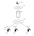
- FIG. 1 is an explanatory diagram showing an example of an information processing method according to an embodiment.
- FIG. 2 is an explanatory diagram showing an example of an information processing system.
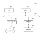
- FIG. 3 is a block diagram showing an example of the hardware configuration of the information processing device.
- FIG. 4 is an explanatory diagram showing an example of the stored contents of the machine tool state information table.
- FIG. 5 is an explanatory diagram showing an example of the storage contents of the maintenance information table.
- FIG. 6 is an explanatory diagram showing an example of the stored contents of the line arrangement information table.
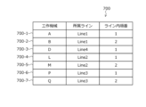
- FIG. 7 is an explanatory diagram showing an example of the stored contents of the machine tool arrangement information table.
- FIG. 8 is a block diagram showing an example of the hardware configuration of a machine tool.
- FIG. 8 is a block diagram showing an example of the hardware configuration of a machine tool.
- FIG. 9 is a block diagram showing an example of the hardware configuration of the client device.
- FIG. 10 is a block diagram showing an example of the functional configuration of the information processing device.
- FIG. 11 is a functional block diagram showing a first example of operation of the information processing device.
- FIG. 12 is an explanatory diagram of an example of calculation of loss cost due to planned stoppage of a line.
- FIG. 13 is an explanatory diagram showing an example of replacement timing optimized by multi-objective optimization.
- FIG. 14 is a diagram showing a maintenance plan selection screen output by the information processing device.
- FIG. 15 is a diagram showing a detailed screen of a draft maintenance plan output by the information processing device.
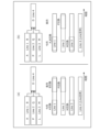
- FIG. 16 is an explanatory diagram comparing the conventional technology and the embodiment regarding the influence of planned shutdown.
- FIG. 17 is a functional block diagram showing a second example of operation of the information processing device.
- FIG. 18 is a flowchart showing an example of the overall processing procedure.
- FIG. 19 is a flowchart illustrating a detailed procedure example of a process for generating a predictive model of remaining life.
- FIG. 20 is a flowchart illustrating a detailed procedure example of the remaining life prediction process.
- FIG. 21 is a flowchart illustrating a detailed procedure example of a process for creating a plurality of maintenance plan proposals.
- FIG. 1 is an explanatory diagram showing an example of an information processing method according to an embodiment.
- the information processing device 100 is, for example, a server, a PC (Personal Computer), a cloud on a network, or the like.
- the information processing device 100 creates a maintenance plan for each device 110 of a plurality of devices 110 arranged on the target flow and each in charge of different tasks, indicating the timing of replacement work that will involve stopping all or part of the target flow. create.
- the information processing device 100 creates a maintenance plan that optimizes the replacement timing of each of the plurality of devices 110, and presents it to the user in an easy-to-understand display.
- the information processing device 100 processes, for example, a production line in which a plurality of devices 110 assemble different parts to produce products.
- the plurality of devices 110 are, for example, machine tools.
- the "device 110" is also specifically described as the "machine tool 110" on the production line.
- the production line serializes the product assembly process and the arrangement of machine tools 110, and produces products in an assembly line.
- the information processing device 100 performs replacement work that involves stopping the entire production line or a part of the line in which the machine tools 110 are installed, before a failure occurs due to deterioration over time of the devices of the plurality of machine tools 110. Output a maintenance plan showing timing.
- the replacement work is performed on the entire device 110 or some parts such as the operating unit that constitute the device 110, and any replacement involves stopping the device 110. Therefore, the description of "device 110" described below includes “parts of device 110.”
- the information processing device 100 acquires information regarding the deadline for implementing replacement work that involves stopping all or part of the target flow for a plurality of machine tools 110 arranged on a production line. For example, the information processing device 100 acquires measurement data measured by a sensor provided in each machine tool 110 as information regarding the deadline.
- the measurement data is data indicating operations and conditions that can be used for maintenance such as failure and replacement of the machine tool 110.
- Device a performs a predetermined work A on a product on a product production line
- device b performs a predetermined work B
- device c performs a predetermined work C.
- the devices a to c on the production line are not limited to line connection configurations in which they are connected in a straight line, but also include line connection configurations in which they are branched or combined in the middle.
- the costs incurred due to the production line stoppage include the cost of not being able to produce products due to the stoppage of the machine tool 110, and the parts replacement cost related to the parts cost of the machine tool 110, parts replacement work, and the remaining usage period of the parts.
- parts replacement costs for example, a predictive maintenance technique can be used that grasps or predicts the deterioration state of the machine tool 110 and performs maintenance as necessary. With this predictive maintenance, by predicting when to replace parts of each machine tool 110 on the production line, it is possible to make the most of each part, compared to regular maintenance. By making maximum use of individual parts, parts replacement costs can be reduced.
- the conventional technology it is possible to predict the replacement timing of parts of each machine tool 110 and reduce the cost of parts replacement.
- the timing for replacing parts of each machine tool 110 is not taken into consideration.
- the production line will correspondingly stop multiple times. The number of production line stops will increase.
- a production line may have various line connection configurations, such as multiple partial lines branching out or joining together midway. Further, a plurality of machine tools 110 may be arranged for each partial line, and there are various line connection configurations.
- the prior art does not consider such various line connection configurations. For this reason, in the conventional technology, if parts are replaced at each predicted replacement time for each machine tool 110, the number of machines to be stopped increases, and the number of times maintenance for part replacement increases correspondingly, resulting in lower production costs. do. In addition, the entire production line may be stopped, and in this case, products cannot be manufactured and loss costs increase.
- the information processing device 100 performs the following processing.
- the information processing device 100 acquires information regarding the deadline for replacing the machine tool 110 or replacing parts of the machine tool 110 from each of the plurality of machine tools 110, and calculates the remaining life of the machine tool 110.
- the remaining life of the machine tool 110 is calculated.
- the information processing device 100 acquires measurement data measured by each sensor of the machine tools 110, and calculates the remaining life of the plurality of machine tools 110 based on the acquired measurement data.
- the remaining life represents, for example, the remaining usable time until the machine tool 110 or the parts of the machine tool 110 reach a life limit in which they can stably operate without breaking.
- the information processing device 100 may calculate the deadline using a learning model. For example, the information processing device 100 acquires measurement data measured in the past by a sensor provided in each machine tool 110 and the time when each machine tool 110 was replaced in the past. The information processing device 100 learns a model for outputting a deadline for performing replacement work for each machine tool 110 in response to input of measurement data. The information processing device 100 uses the learned model for each machine tool 110 to calculate a deadline for performing the replacement work based on the measurement data.
- the measurement data measured by the sensor indicates a sensor value corresponding to a change in the operating state of the machine tool 110 over time, and the information processing device 100 controls the machine tool 110 based on the fluctuation state of the sensor value of this measurement data. It is possible to predict a deadline corresponding to the lifespan of Further, the information processing device 100 may calculate the remaining life based on the difference between the life limit (endurance time) defined for the machine tool 110 and the predicted deadline.
- the information processing device 100 creates a maintenance plan from the calculated remaining life.
- the information processing device 100 calculates a plurality of timings for replacing the machine tool 110 or replacing parts of the machine tool 110 as a maintenance plan.
- the information processing device 100 calculates one or more combinations of times when replacement work is to be performed for each machine tool 110 as a plurality of maintenance plans, and presents the combinations to the user. For example, the information processing device 100 performs multi-objective optimization using a first objective function and a second objective function, and calculates one or more combinations of timings for performing replacement work that form a maintenance plan.
- (1-2-1) Processing for setting the first objective function for replacing machine tools 110
- the information processing device 100 performs replacement work for each machine tool 110 ahead of schedule before reaching the end of its remaining life.
- a first objective function including a first cost formula according to the remaining life of each machine tool 110 in the assumed case is set.
- the information processing device 100 sets the sum of the parts replacement cost and loss cost for each machine tool 110 as the first cost.
- the parts replacement cost is the cost of procuring new parts when replacing the machine tool 110 or replacing parts of the machine tool 110.
- the loss cost corresponds to the loss of value when a component with remaining life is removed before the end of its life.
- the information processing apparatus 100 sets the loss cost due to the advance payment using the following formula (1).
- Loss cost due to bringing it forward parts cost x (predicted remaining life/elapsed time + predicted remaining life)...(1)
- the information processing device 100 sets the loss cost due to bringing the parts replacement forward, including the remaining life, and reduces the loss.
- the cost is included in the first cost.
- (1-2-2) Processing for setting a second objective function for replacing machine tools 110 The information processing device 100 performs a replacement work on each machine tool 110 when it is assumed that the replacement work will be performed before the deadline.
- a second objective function is set that includes a second cost formula depending on the period during which all or part of the production line is stopped due to each of these. For example, the information processing device 100 sets, as the second cost, the total loss cost due to production stoppage when production on the production line is planned to be stopped due to each replacement work in the line connection configuration indicated by the production line. .
- Planned stoppage is also called planned downtime, and means a planned stoppage of the production line for maintenance of the machine tool 110.
- unplanned downtime means an unexpected line stop such as a failure of the machine tool 110.
- the information processing device 100 calculates one or more combinations of timings for performing replacement work for each machine tool 110 as a plurality of maintenance plans. Calculate and present to the user.
- the information processing device 100 performs multi-objective optimization using a first objective function and a second objective function, and calculates one or more combinations of times to perform replacement work that form a maintenance plan.
- the information processing device 100 narrows down and presents to the user combinations that are candidates for a maintenance plan, from among the infinite combinations of times when replacement work is performed by combining a plurality of machine tools 110. .
- the information processing device 100 calculates the remaining life of each machine tool 110 in the case where replacement work is performed before the remaining life of each machine tool 110 is reached. Let the corresponding first cost be the first objective function.
- the information processing device 100 when replacing each machine tool 110 before the remaining life is reached, can replace the entire production line or A second cost corresponding to a part of the suspension period is set as a second objective function.
- the information processing device 100 calculates one or more optimal combinations of timings for performing replacement work for each machine tool 110 by performing multi-objective optimization using a first objective function and a second objective function. .
- the information processing device 100 calculates a Pareto solution.
- the information processing device 100 considers both the cost of replacing parts of the machine tool 110 and the loss cost due to planned stoppage of the production line, narrows down the replacement timing, and calculates a plurality of optimized replacement timings. .
- the information processing device 100 presents a maintenance plan for multiple replacement times, which has a relationship between component replacement costs and loss costs due to planned stoppages of the production line, in a form that is easy for the user to understand.
- the information processing device 100 presents and outputs the maintenance plan for the production line to the user's client device 150.
- the information processing device 100 creates a maintenance plan for a two-month maintenance period based on input of a maintenance period for a production line through a user operation of the client device 150, and displays and outputs the maintenance plan to the client device 150. do.
- the information processing device 100 displays, for example, the trade-off relationship for each machine tool 110 placed on the production line using a Pareto solution characteristic curve. For example, the information processing device 100 displays and outputs information on a characteristic curve of a Pareto solution to the client device 150, with the vertical axis representing parts replacement cost and the horizontal axis representing loss cost due to planned stoppage of the production line.
- the information processing device 100 calculates the parts replacement cost when replacing each point and the loss cost due to planned stoppage of the production line. Print out a guide on the trade-offs. For example, the information processing device 100 displays and outputs information on the merits and demerits of parts replacement costs for each point and loss costs due to planned production line stoppages to the client device 150 as a guide regarding trade-offs, and provides the user with an intuitive display. Let them understand.
- the information processing device 100 determines a specific maintenance plan corresponding to the selected point based on the user's selection of one of the plurality of replacement timing points located on the characteristic curve of the Pareto solution displayed on the client device 150. Display output. For example, the information processing device 100 displays the timing to stop replacing each machine tool 110 on a production line, displays the machine tools 110 whose replacement will be stopped earlier than expected, and displays that the replacement will be stopped earlier.
- the information processing device 100 creates a maintenance plan that takes into account the cost of replacing parts of each machine tool 110 on the production line, as well as the impact of stopping the production line due to parts replacement, and presents it to the user. do.
- the information processing device 100 specifically presents to the user, as a maintenance plan, the trade-off relationship between parts replacement costs and loss costs due to planned stoppage of the production line, and allows the user to understand the advantages and disadvantages of each replacement period. can be done. Thereby, the user can appropriately and easily determine when to replace each machine tool 110 based on the maintenance plan presented by the information processing device 100.
- FIG. 2 is an explanatory diagram showing an example of an information processing system.
- the information processing system includes an information processing device 100, a client device 150, and machine tools 110-1 to 110-n arranged on a production line. It also includes sensors 202-1 to 202-n (n is a natural number of 2 or more) provided in each of the machine tools 110-1 to 110-n.
- the machine tools 110-1 to 110-n may be referred to as “machine tools 110”
- the sensors 202-1 to 202-n may be referred to as "sensors 202.”
- the information processing device 100 and the sensors 202-1 to 202-n are connected via a wired or wireless network 210.
- the information processing device 100 and the client device 150 are connected via a wired or wireless network 210.
- the network 210 is, for example, a LAN (Local Area Network), a WAN (Wide Area Network), the Internet, or the like.
- the client device 150 outputs a request to create a maintenance plan for the machine tool 110 on the production line to the information processing device 100 in response to a user operation.
- the information processing device 100 displays the created maintenance plan on the client device 150 using a web service on the network 210.
- the information processing device 100 is a computer that has various information processing tables shown in FIGS. 4 to 7, and creates a maintenance plan and output control for the machine tools 110 on the production line based on the information in the various information processing tables. be.
- the information processing device 100 is, for example, a server.
- the client device 150 is, for example, a computer that has a display (for example, a display 912 shown in FIG. 9 described later) and can display various screens of the maintenance plan according to the display control of the information processing device 100.
- the client device 150 is, for example, a PC, a notebook PC, a tablet PC, a smartphone, a wearable terminal, or the like.
- the information processing device 100 When the information processing device 100 receives a request to display a maintenance plan for the machine tool 110 on the production line from the client device 150, the information processing device 100 generates screen information for various screens of the maintenance plan based on information in various tables, and displays the screen information on the client device 150. Send to. As a result, the client device 150 displays various screens on the display.
- the information processing method of the embodiment creates a maintenance plan for a plurality of machine tools 110 arranged on a production line.
- the production line to which the information processing method of the embodiment is applied is not limited to one in which a plurality of machine tools 110 are simply arranged in a straight line.
- it may be a production line in which a plurality of partial lines arranged in parallel merge into the same partial line, or a certain partial line branches into a plurality of partial lines.
- the information processing device 100 determines whether the machine tool 110, which is in charge of the work of forming one of two or more partial flows, is responsible for the second cost related to stopping the production line, and the second cost related to the stoppage of the production line. Calculate the cost according to the outage period.
- the CPU 301 controls the entire information processing device 100.
- the memory 302 includes, for example, a ROM (Read Only Memory), a RAM (Random Access Memory), a flash ROM, and the like. Specifically, for example, a flash ROM or ROM stores various programs, and a RAM is used as a work area for the CPU 301.
- the program stored in the memory 302 is loaded into the CPU 301 and causes the CPU 301 to execute the coded processing.
- the network I/F 303 is connected to a network 210 through a communication line, and is connected to other computers via the network 210.
- the network I/F 303 serves as an internal interface with the network 210, and controls data input/output from other computers.
- the network I/F 303 is, for example, a modem or a LAN adapter.
- the recording medium I/F 304 controls reading/writing of data to/from the recording medium 305 under the control of the CPU 301.
- the recording medium I/F 304 is, for example, a disk drive, an SSD (Solid State Drive), a USB (Universal Serial Bus) port, or the like.
- the recording medium 305 is a nonvolatile memory that stores data written under the control of the recording medium I/F 304.
- the recording medium 305 is, for example, a disk, a semiconductor memory, a USB memory, or the like.
- the recording medium 305 may be removable from the information processing apparatus 100.
- the information processing device 100 may include, for example, a keyboard, a mouse, a display, a printer, a scanner, a microphone, a speaker, and the like. Further, the information processing apparatus 100 may include a plurality of recording medium I/Fs 304 and recording media 305. Further, the information processing apparatus 100 does not need to have the recording medium I/F 304 or the recording medium 305.
- the information processing table is realized, for example, by a storage area such as the memory 302 or the recording medium 305 of the information processing apparatus 100 shown in FIG. 3.
- FIG. 4 is an explanatory diagram showing an example of the stored contents of the machine tool status information table.
- the machine tool status information table 400 includes measurement data, such as sensor values, that the sensor 202 of the machine tool 110 periodically outputs, for example, in association with fields of the machine tool 110. It has fields for , elapsed time, and durability time.
- machine tool status information is stored as a record 400-a by setting information in each field for each machine tool.
- a is any integer.
- a is any integer from 1 to 7.
- Machine tools are identifiers A to Q of machine tools 110 placed on the production line.
- the sensor value is the operating state of the machine tool 110 detected by the sensor 202.
- the elapsed time is the elapsed time since the machine tools A to Q were last replaced.
- the durability time is the time required to ensure stable operation of the machine tool 110 and its parts. Replacement during the period until the elapsed time reaches the durability time corresponds to early replacement of the device 110.
- the sensor 202 is not limited to detecting sensor values, elapsed time, and durability time, which are measurement data.
- the information processing device 100 sets a fixed value in the machine tool status information table 400 for the durability time of a part of the measurement data, and the information processing device 100 sets the elapsed time by setting the time after the device 110 is replaced for each timer count. It may also be stored in the machine tool status information table 400.
- record 400-1 is maintenance information that associates the sensor value of machine tool A with AAA, the elapsed time with a1, and the durability time with ax.
- the machine tool status information table 400 is created, for example, by adding a record 400-a each time the sensor 202 provided for each machine tool 110 outputs periodic measurement data. Furthermore, the machine tool 110 is composed of a combination of parts, and the machine tool status information table 400 includes, for example, records 400- It may be created by adding a.
- FIG. 5 is an explanatory diagram showing an example of the storage contents of the maintenance information table.
- the maintenance information table 500 has fields for machine tool manufacturer and planned downtime in association with the machine tool field.
- maintenance information is stored as a record 500-a by setting information in each field for each machine tool.
- a is any integer.
- a is any integer from 1 to 7.
- Machine tools are identifiers A to Q of machine tools 110 placed on the production line.
- the machine tool manufacturer is the manufacturer name X to Z of the machine tool manufacturer.
- the planned stop time is the time during which machine tools A to Q are stopped when replaced, and in the example of FIG. 5, it is 2, 3, and 5 (days).
- record 500-1 is maintenance information that associates machine tool A with manufacturer X and planned downtime of 3 days.
- the maintenance information table 500 is created, for example, by adding a record 500-a based on an operation input of the client device 150 by a worker engaged in maintenance planning.
- FIGS. 6 and 7 each show an example of the stored contents of the line configuration table.
- the line configuration table includes a line arrangement information table and a machine tool arrangement information table.
- FIG. 6 is an explanatory diagram showing an example of the stored contents of the line arrangement information table.
- the line arrangement information table 600 has fields for process, front line, back line, and production amount in association with the partial line field.
- line arrangement information is stored as a record 600-a by setting information in each field for each partial line.
- a is any integer.
- a is any integer from 1 to 4.
- the lines are identifiers Line1 to Line4 for each partial line arranged on the production line.
- the process refers to identifiers 1 to 3 for each production process on the production line.
- the previous line is an identifier of a partial line located before the own partial line on the production line.
- the subsequent line is an identifier of a partial line located after the own partial line.
- the production amount is the amount of products produced on the own line.
- the record 600-1 is line arrangement information that associates that line Line 1 produces processes 1 and 2, the subsequent line is Line 4, and the production amount is 10.
- the record 600-4 is line arrangement information in which line Line 4 performs production in process 3, the previous lines are Line 1, Line 2, Line 3, and the production amount is 40.
- three parallel partial lines Line1 to Line3 are shown to be a production line connected to one Line4.
- the line arrangement information table 600 is created, for example, by adding a record 600-a based on the operation input of the client device 150 by a worker engaged in maintenance planning.
- FIG. 7 is an explanatory diagram showing an example of the stored contents of the machine tool arrangement information table.
- the machine tool arrangement information table 700 has fields for the line to which the machine tool belongs and the order within the line, in association with the field for the machine tool.
- machine tool location information is stored as a record 700-a by setting information in each field for each machine tool.
- a is any integer.
- a is any integer from 1 to 7.
- Machine tools are identifiers A to Q of machine tools 110 placed on the production line.
- the belonging lines are partial lines Lines 1 to 4 where the machine tools are arranged.
- the in-line order is the arrangement position of the own machine tools on the partial line, and in the example of FIG. 7, the front arrangement is 1 and the rear arrangement is 2.
- the record 700-1 is machine tool arrangement information that associates machine tool A with the belonging line being partial line Line1 and the order within the line being 1.
- record 700-2 is machine tool arrangement information that associates machine tool B with the belonging line as partial line Line1 and the order within the line as 2.
- the partial line Line 1 shows that machine tool A is arranged in the front and machine tool B is arranged in the rear.
- the machine tool location information table 700 is created, for example, by adding a record 700-a based on an operation input on the client device 150 by a worker engaged in maintenance planning.
- FIG. 8 is a block diagram showing an example of the hardware configuration of a machine tool.
- the machine tool 110 includes a CPU 801, a memory 802, a network I/F 803, an operation unit 810, a sensor 811, and a touch panel 812. Further, each component is connected to each other by a bus 800.
- Memory 802 includes, for example, ROM, RAM, flash ROM, and the like. Specifically, for example, a flash ROM or ROM stores various programs, and a RAM is used as a work area for the CPU 801. The program stored in the memory 802 is loaded into the CPU 801 and causes the CPU 801 to execute the coded processing.
- the network I/F 803 is connected to a network 210 through a communication line, and is connected to other computers via the network 210.
- Network I/F 803 is connected to information processing device 100 via network 210, for example.
- the network I/F 803 serves as an internal interface with the network 210, and controls data input/output from other computers.
- the network I/F 803 is, for example, a communication circuit that communicates with the wired or wireless network 210.
- the network I/F 803 may be a communication circuit having a Wi-Fi (registered trademark) antenna.
- the operating unit 810 constitutes the machine tool 110 and corresponds to a part to be replaced.
- the machine tool 110 manufactures products through the operation of the operation unit 810.
- the operation unit 810 is, for example, a manipulator.
- the operation unit 810 is controlled by the operation control of the CPU 801 and performs operations such as incorporating parts of a product to be manufactured into the product in accordance with the steps in the flow that the machine tool 110 is responsible for.
- the sensor 811 corresponds to the sensor 202 in FIG. 2.
- the sensor 811 detects the operating state of the operating unit 810 and periodically outputs measurement data to the information processing device 100.
- the sensor 811 measures measurement data related to the operation of the operation unit 810, for example.
- the measurement data outputs the amount of displacement of the operation or situation used for maintenance such as failure or replacement of the operation unit 810 as a sensor value.
- the sensor 811 may include, for example, at least one of an acceleration sensor, a geomagnetic sensor, a light sensor, a vibration sensor, a strain detection sensor, an infrared sensor, and the like.
- the sensor 811 outputs a sensor value indicating the amount of displacement of the operating unit 810 to the information processing device 100.
- the touch panel 812 displays various information about the machine tool 110 controlled by the CPU 801. Further, the touch panel 812 is used to set the operation of the machine tool 110, information output, etc. by touch operation.
- FIG. 9 is a block diagram showing an example of the hardware configuration of the client device.
- the client device 150 includes a CPU 901, a memory 902, a network I/F 903, a recording medium I/F 904, a recording medium 905, an input/output I/F 910, an input device 911, and a display 912. have Further, each component is connected to each other by a bus 900.
- Memory 902 includes, for example, ROM, RAM, flash ROM, and the like. Specifically, for example, a flash ROM or ROM stores various programs, and a RAM is used as a work area for the CPU 901. The program stored in the memory 902 is loaded into the CPU 901 and causes the CPU 901 to execute the coded processing.
- the network I/F 903 is connected to a network 210 through a communication line, and is connected to other computers via the network 210.
- the network I/F 903 serves as an internal interface with the network 210, and controls data input/output from other computers.
- the network I/F 903 is, for example, a modem or a LAN adapter.
- the recording medium I/F 904 controls reading/writing of data to/from the recording medium 905 under the control of the CPU 901.
- the recording medium I/F 904 is, for example, a disk drive, an SSD, a USB port, or the like.
- the recording medium 905 is a nonvolatile memory that stores data written under the control of the recording medium I/F 904.
- the recording medium 905 is, for example, a disk, a semiconductor memory, a USB memory, or the like.
- the recording medium 905 may be removable from the client device 150.
- the input/output I/F 910 controls input/output of data to and from the input device 911 and the display 912 under the control of the CPU 901.
- the input device 911 has keys for inputting characters, numbers, various instructions, etc., and inputs data.
- the input device 911 may be a keyboard, a mouse, or the like, or may be a touch panel type input pad, a numeric keypad, or the like.
- Display 912 displays data such as a cursor, icons, or toolbox, as well as documents, images, and functional information.
- the display 912 is, for example, a CRT (Cathode Ray Tube), a liquid crystal display, an organic EL (Electroluminescence) display, or the like.
- the client device 150 may include, for example, a printer, a scanner, a microphone, a speaker, and the like. Further, the client device 150 may include a plurality of recording medium I/Fs 904 and recording media 905. Further, the client device 150 does not need to have the recording medium I/F 904 or the recording medium 905.
- FIG. 10 is a block diagram showing an example of the functional configuration of the information processing device.
- the information processing device 100 includes a storage unit 1001, an acquisition unit 1002, a calculation unit 1003, and an output unit 1004.
- the storage unit 1001 is realized, for example, by a storage area such as the memory 302 or the recording medium 305 shown in FIG. 3.
- a storage area such as the memory 302 or the recording medium 305 shown in FIG. 3.
- the invention is not limited to this.
- the storage unit 1001 is included in a device different from the information processing device 100, and the storage contents of the storage unit 1001 can be referenced from the information processing device 100.
- the acquisition unit 1002 to output unit 1004 function as an example of a control unit. Specifically, the acquisition unit 1002 to the output unit 1004 execute the program by causing the CPU 301 to execute a program stored in a storage area such as the memory 302 or the recording medium 305 shown in FIG. This function is realized by The processing results of each functional unit are stored in a storage area such as the memory 302 or the recording medium 305 shown in FIG. 3, for example.
- the storage unit 1001 stores various information that is referenced or updated in the processing of the acquisition unit 1002 to output unit 1004, which are the functional units of the control unit.
- the acquisition unit 1002 acquires various information used in the processing of each functional unit.
- the acquisition unit 1002 stores the acquired various information in the storage unit 1001 or outputs it to each functional unit. Further, the acquisition unit 1002 may output various information stored in the storage unit 1001 to each functional unit.
- the acquisition unit 1002 acquires various information based on, for example, a user's operation input.
- the acquisition unit 1002 may receive various information from a device different from the information processing device 100, for example.
- the acquisition unit 1002 may receive a start trigger that starts processing of any functional unit.
- the start trigger is, for example, a predetermined operation input by the user.
- the start trigger may be, for example, receiving predetermined information from another computer.
- the start trigger may be, for example, that any functional unit outputs predetermined information.
- the output unit 1004 outputs the processing results of each functional unit.
- the output format is, for example, displaying on a display, printing out to a printer, transmitting to an external device via network I/F 303, or storing in a storage area such as memory 302 or recording medium 305.
- the output unit 1004 notifies the user of the processing results of each functional unit, for example, information such as the cost and timing of replacing the machine tool 110 on the production line, and allows the user to implement a maintenance plan for the production line. We can support you.
- the acquisition unit 1002 acquires information from a plurality of machine tools 110, each of which is in charge of a different task among a plurality of operations forming a production line, for replacement that involves stopping all or part of the production line.
- the deadline is, for example, the time when the replacement work is performed by maximizing the durability of the device 110.
- the storage unit 1001 contains and stores information on the machine tool status information table 400, maintenance information table 500, line arrangement information table 600, and machine tool arrangement information table 700, which are the information processing tables described above.
- the acquisition unit 1002 acquires measurement data detected by the sensors 202 of each of the plurality of machine tools 110 and stores it in the machine tool status information table 400.
- the acquisition unit 1002 acquires the information of the maintenance information table 500, the line layout information table 600, and the machine tool layout information table 700 through external input such as a user operation, and stores the information in the storage unit 1001.
- the calculation unit 1003 calculates the optimal time to perform the replacement work for each machine tool 110 based on the information acquired by the acquisition unit 1002.
- the calculation unit 1003 includes a remaining life calculation unit 1010, a first objective function setting unit 1011, a second objective function setting unit 1012, and a multi-objective optimization unit 1013.
- the remaining life calculation unit 1010 obtains information regarding the deadline for replacing the machine tool 110 or replacing parts of the machine tool 110 from each of the plurality of machine tools 110, and calculates the remaining life of the plurality of machine tools 110.
- the information processing device 100 acquires measurement data measured by each sensor of the machine tools 110, and calculates the remaining life of the plurality of machine tools 110 based on the acquired measurement data.
- the remaining life calculation unit 1010 calculates the remaining life of each machine tool 110 based on, for example, information on the sensor value, elapsed time, and durability time of each machine tool 110 as measurement data.
- the remaining life calculation unit 1010 may calculate the remaining life of the plurality of machine tools 110 by performing a learning process.
- the remaining life calculation unit 1010 acquires measurement data measured in the past by a sensor provided in each machine tool 110 and the time when each machine tool 110 was replaced in the past.
- the information processing device 100 learns a model for outputting a deadline for performing replacement work for each machine tool 110 in response to input of measurement data.
- the information processing device 100 uses the learned model for each machine tool 110 to calculate a deadline for performing the replacement work based on the measurement data.
- the measurement data measured by the sensor indicates a sensor value corresponding to a change in the operating state of the machine tool 110 over time, and the information processing device 100 controls the machine tool 110 based on the fluctuation state of the sensor value of this measurement data. Predict a deadline corresponding to the lifespan of Further, the information processing device 100 may calculate the remaining life based on the difference between the life limit (endurance time) defined for the machine tool 110 and the predicted deadline.
- the first objective function setting unit 1011 and the second objective function setting unit 1012 set a first objective function and a second objective function used for multi-objective optimization by the multi-objective optimization unit 1013.
- the first objective function setting unit 1011 sets a first objective function according to the remaining life of each machine tool 110 in a case where it is assumed that replacement work is carried out ahead of schedule before the remaining life is reached for each machine tool 110.
- a first objective function including a cost expression is set.
- the first objective function setting unit 1011 refers to information such as the sensor value, elapsed time, and durability time of each machine tool 110 stored in the machine tool status information table 400 stored in the storage unit 1001, for example.
- the first objective function setting unit 1011 calculates, as the basic cost, the cost when the machine tool 110 is used until the elapsed durability time expires, that is, when the machine tool 110 has no remaining life and is used until the life limit. In addition, the first objective function setting unit 1011 calculates the cost of replacing the machine tool 110 before its durability time has expired, that is, the loss that would occur if the machine tool 110 was replaced earlier than the basic cost. Set the cost.
- the second objective function setting unit 1012 sets a second cost corresponding to the suspension period of all or part of the production line due to each replacement work when the replacement work is performed before the deadline for each machine tool 110.
- Each machine tool 110 is arranged on a part of the production line, and depending on the arrangement of the machine tools 110 on the production line, if the machine tool 110 is stopped, a part of the production line is stopped. In this case, the entire production line is stopped.
- the second objective function setting section 1012 determines the arrangement of each machine tool 110 on the production line, which is stored in the maintenance information table 500, line arrangement information table 600, and machine tool arrangement information table 700 stored in the storage section 1001. View information such as planned downtime.
- the second objective function setting unit 1012 sets the loss cost due to the production stop when production on the production line is planned to stop.
- the multi-objective optimization unit 1013 performs multi-objective optimization using the first cost set by the first objective function setting unit 1011 as the first objective function and the second cost calculated by the second objective function setting unit 1012 as the second objective function. Process. Through the multi-objective optimization process, the multi-objective optimization unit 1013 calculates one or more optimal combinations of timings for performing replacement work for each machine tool 110, for example, a Pareto solution.
- the output unit 1004 outputs information on one or more optimal combinations of times to perform replacement work for each machine tool 110 calculated by the multi-objective optimization unit 1013.
- the output unit 1004 outputs information to the client device 150 shown in FIG. 2, for example.
- the output of the output unit 1004 takes into account both the cost of replacing parts of the machine tool 110 and the loss cost due to planned stoppage of the production line, and indicates a plurality of optimal replacement timings. .
- FIG. 11 is a functional block diagram showing a first example of operation of the information processing device.
- the same components as those described above are given the same reference numerals.
- FIG. 11 shows a detailed example of the function of the calculation unit 1003 of the information processing apparatus 100 shown in FIG. 10.
- Machine tools A to C (110) are each provided with a sensor 202.
- the sensor 202 outputs measurement data of the machine tools A to C (110) to the information processing device 100.
- the information processing device 100 includes the above-described first objective function setting section 1011, second objective function setting section 1012, multi-objective optimization section 1013, and output section 1004.
- the information processing device 100 also includes a remaining life calculation section 1010 and a maintenance planning section 1110.
- the remaining life calculation unit 1010 includes a learning data generation unit 1101, a learning unit 1102, a remaining life inference unit 1103, and an inference data generation unit 1104, and calculates the remaining life of the device 110.
- the learning data generation unit 1101 to the remaining life inference unit 1103 perform learning of predictive models for the remaining life of each machine tool 110.
- the learning data generation unit 1101 creates learning data for predicting the remaining life of each machine tool 110 based on the information stored in the machine tool status information table 400.
- the learning data generation unit 1101 generates learning data related to changes in sensor values for each elapsed time of the machine tool 110 stored in the machine tool state information table 400, for example.
- the learning data generation unit 1101 creates learning data for each machine tool 110 and for each component (operation unit 810) included in each machine tool 110.
- the learning unit 1102 performs a learning process of a model that predicts the remaining life of each machine tool 110 and each component using the learning data generated by the learning data generating unit 1101.
- the learning unit 1102 performs learning using, for example, a machine learning (ML) algorithm such as linear regression, GBDT (Gradient Boosting Decision Tree), or NN (Neural Network).
- ML machine learning
- a model is created by changing the parameters of the NN so that the error from the correct label until the label is replaced is reduced.
- the remaining life inference unit 1103 outputs a model that predicts the remaining life of each machine tool 110 and each component based on the learning results of the learning unit 1102.
- the inference data generation unit 1104 generates inference data for each machine tool 110, for example, based on sensor values for each elapsed time of the machine tool 110 stored in the machine tool state information table 400.
- the inference data generation unit 1104 inputs the generated inference data to the trained remaining life prediction model output by the remaining life inference unit 1103, and calculates a predicted value of the remaining life.
- the inference data generation unit 1104 may store the calculated predicted value of the remaining life in the field of the record of the corresponding machine tool 110 in the machine tool status information table 400.
- the first objective function setting unit 1011 performs the calculation process of the above formula (1) using the remaining life information obtained through the learning process by the remaining life calculation unit 1010, and sets the loss cost due to the front-loading of the machine tool 110. .
- the second objective function setting unit 1012 sets the loss cost due to planned stoppage of the line.
- the multi-objective optimization unit 1013 calculates an optimal solution for the combination of the loss cost due to the advance set by the first objective function setting unit 1011 and the loss cost due to planned line stoppage set by the second objective function setting unit 1012.
- the maintenance planning unit 1110 creates a maintenance plan including the replacement timing of the machine tool 110 based on the optimal solution of the combination of the loss cost due to the advance and the loss cost due to the planned stoppage of the line calculated by the multi-objective optimization unit 1013. do.
- the output unit 1004 displays and outputs the maintenance plan created by the maintenance planning unit 1110 to the client device 150.
- FIG. 12 is an explanatory diagram of an example of calculation of loss cost due to planned stoppage of a line.
- An example of calculation of loss cost due to planned stoppage of a production line by the second objective function setting unit 1012 will be described with reference to FIG. 12.
- FIG. 12(a) shows an example of a connection configuration in which a plurality of partial lines are combined. Line1, Line2, and Line3, which are arranged in parallel with each other, are connected to Line4.
- Machine tool A is arranged at the front stage and machine tool B is arranged at the rear stage.
- a machine tool P is arranged at the front stage, and a machine tool Q is arranged at the rear stage.
- a machine tool L is arranged at the front stage, and a machine tool M is arranged at the rear stage.
- Each Line1 to Line3 is connected to Line4 at the subsequent stage.
- Machine tool D is placed on Line 4.
- x be the sales per day based on the production volume of the entire production line. Further, it is assumed that the production amount of each partial line is 1/4 for Line 1, 1/2 for Line 2, and 1/4 for Line 3. In this case, the loss cost per day due to planned stoppage of each partial line is x/4 for Line 1, x/2 for Line 2, x/4 for Line 3, and x for Line 4.
- the information processing device 100 calculates the loss cost due to the planned stoppage, taking into account the connection configuration of the production line. For example, when maintenance is performed on machine tool D, the production of the entire line is stopped, resulting in a large loss cost due to the planned stoppage. On the other hand, for machine tools A, B, P, Q, L, and M, production can be reduced if separate partial lines are in operation, and the loss cost of planned stoppages is relatively low.
- FIG. 12(b) shows a state in which setting contents equivalent to the maintenance information table 500 described above are distributed as machine tools 110 for each manufacturer.
- a production line may include multiple machine manufacturers.
- the scheduled downtime may vary depending on the manufacturer.
- the planned downtime for each product type is set in the maintenance information table 500.
- machine tools A, B, L, and M are manufactured by manufacturer X, and the planned downtime is 3 days.
- the manufacturer of machine tools P and Q is Y, and the planned downtime is 5 days.
- the loss cost increases due to planned stoppages. More specifically, for example, when machine tool A makes a planned stop, a loss cost of x/4 ⁇ 3 (days) occurs in Line 1. Furthermore, when the machine tool P makes a planned stop, a loss cost of x/2 ⁇ 5 (days) occurs in Line 2.
- the information processing device 100 calculates the loss cost at the time of a planned stoppage, taking into consideration the planned stoppage time that varies depending on the manufacturer of the machine tool 110 on the production line. For example, regarding the second cost, when performing replacement work on the machine tool 110, the information processing device 100 calculates a planned downtime for each partial line due to the replacement work, and a weighting coefficient representing the degree of influence of the partial line on the entire production line. Set costs accordingly. For example, the weighting coefficient corresponds to the coefficient expressed by x/4 ⁇ 3 (days) for each partial line.
- Multi-objective optimization processing example 1 Next, a first example of multi-objective optimization processing by the multi-objective optimization unit 1013 will be described.
- the multi-objective optimization unit 1013 calculates an optimal solution for the combination of the first cost (parts replacement cost + loss cost) and the second cost (loss cost due to planned stoppage of the production line), which have a trade-off relationship with each other.
- the multi-objective optimization unit 1013 minimizes the first cost and the second cost while changing the parameters of the first cost and the second cost using a combination optimization processing technique of the first cost and the second cost.
- the replacement time of the machine tool 110 is calculated.
- the multi-objective optimization unit 1013 uses an optimization solver to find a plurality of combinations that minimize the first cost and the second cost, which have a trade-off relationship with each other as two objective functions. At this time, the multi-objective optimization unit 1013 changes the parts replacement timing of each machine tool 110 as a parameter (variable). Furthermore, the multi-objective optimization unit 1013 uses a constraint condition that the replacement period of each machine tool 110 does not exceed its remaining life. For example, the multi-objective optimization unit 1013 sets as a constraint condition that the future operating time of each machine tool 110 ⁇ the predicted remaining life of the machine tool.
- the multi-objective optimization unit 1013 calculates the minimization of the first cost using the first objective function shown in equation (2) below.
- the multi-objective optimization unit 1013 calculates the minimization of the second cost using the second objective function shown in equation (3) below.
- the multi-objective optimization unit 1013 sets the following equation (4) as a combination constraint and performs multi-objective optimization processing.
- Multi-objective optimization processing example 2 Next, a second example of multi-objective optimization processing by the multi-objective optimization unit 1013 will be described.
- cost optimization is performed in consideration of factors specific to the manufacturing line. For example, the request destination for replacement work differs depending on the manufacturer of the production line, and the cost of calling a service person for replacement work differs depending on the request destination. Therefore, in processing example 2 of multi-objective optimization, in addition to the costs explained in processing example 1 above, multi-purpose Perform optimization processing.
- machine tools A, B, L, and M are from the same manufacturer.
- the result will be, for example, that machine tools A and B are replaced this month, and machine tool M is replaced next month.
- machine tool M is replaced ahead of schedule this month.
- the multi-objective optimization unit 1013 calculates, for example, the minimization of the first cost using the first objective function shown in equation (2) above.
- the multi-objective optimization unit 1013 calculates the minimization of the second cost using the second objective function shown in equation (3) above.
- the multi-objective optimization unit 1013 uses the third objective function shown in the following formula (5) to minimize the third cost according to a requester who requests replacement work for the machine tool 110 before the deadline, for example. calculate.
- c_i is the cost of replacing parts of machine tool i
- d_j is the loss cost when stopping line j
- s_k is the cost of calling a serviceman from manufacturer k.
- processing example 2 of multi-objective optimization similarly to processing example 1, the above equation (4) is set as a combination constraint condition and multi-objective optimization processing is performed.
- the multi-objective optimization unit 1013 performs multi-objective optimization of the first to third objective functions to determine when to perform the replacement work for each machine tool 110. Calculate one or more combinations.
- FIG. 13 is an explanatory diagram showing an example of replacement timing optimized by multi-objective optimization.
- An example of calculation of the optimal replacement time for each machine tool 110 by the multi-objective optimization unit 1013 will be explained using FIG. 13.
- the horizontal axis in FIG. 13 is time.
- each of the three machine tools A to C starts operating at time t0.
- the remaining life of parts differs depending on machine tools A to C.
- the remaining life of machine tool A expires at time t1.
- the multi-objective optimization unit 1013 replaces parts of machine tool A at time t1, but also checks whether parts can be replaced for machine tool B and C at time t1. , C will be judged based on the remaining life.
- the multi-objective optimization unit 1013 moves forward the parts replacement of machine tool C at time t1 if the parts replacement of machine tool C is appropriate based on the parts replacement timing and cost calculation of each of machine tools B and C. Implemented.
- time t1 machine tools A and C resume operation with new remaining life due to parts replacement. Note that the time t1' is the time when the machine tool C is not replaced ahead of schedule but is replaced at the end of its remaining life.
- the multi-objective optimization unit 1013 replaces parts of machine tool B at time t2, but also determines whether parts can be replaced for other machine tools A and C at time t2. , C will be judged based on the remaining life.
- the multi-objective optimization unit 1013 advances the parts replacement of machine tool A at time t2, if the parts replacement of machine tool A is appropriate, based on the parts replacement timing and cost calculation of each of machine tools A and C. Implemented.
- time t2 machine tools A and B resume operation with new remaining life due to parts replacement. Note that the time t2' is the time when machine tool A is not replaced ahead of schedule but is replaced at the end of its remaining life.
- the multi-objective optimization unit 1013 takes into consideration the remaining life of each of the plurality of machine tools A to C, and can replace the parts of the machine tool 110 whose remaining life has expired ahead of schedule. The presence or absence of other machine tools 110 is determined.
- the information processing device 100 uses multi-objective optimization to determine whether or not parts can be replaced in advance for other machine tools at the same time when replacing parts of a certain machine tool 110, thereby reducing the frequency of production line stoppages. This can reduce loss costs.
- FIGS. 14 and 15 Example of maintenance plan display
- the display screens shown in FIGS. 14 and 15 are created by the maintenance planning unit 1110 based on the multi-objective optimization results by the multi-objective optimization unit 1013 of the information processing device 100.
- the created maintenance plan proposal is displayed and output to the client device 150 via the output unit 1004.
- FIG. 14 is a diagram showing a maintenance plan selection screen output by the information processing device.
- the horizontal axis displayed on the maintenance plan selection screen 1400 shown in FIG. 14 is the loss cost (secondary cost) due to planned stoppage of the production line, and the vertical axis is the machine tool parts replacement cost (first cost). It is.
- the information processing device 100 displays a predetermined characteristic curve 1401 corresponding to a Pareto solution, which is the result of multi-objective optimization of the first cost and the second cost by the multi-objective optimization unit 1013, as a maintenance plan selection screen 1400.
- the characteristic curve 1401 is a combination of multiple times when replacement work is performed for each machine tool 110, and the information processing device 100 displays multiple selection points P1 to P4 on the characteristic curve 1401.
- Each of the selection points P1 to P4 is a maintenance plan proposal that combines conflicting first costs and second costs.
- the information processing apparatus 100 displays a guide 1411 with an explanatory text that reads, "Although there are few line stoppages, the parts will be replaced even though they have remaining life.” Corresponding to the selection point P1. Further, at selection point P4, the loss cost due to planned stoppage of the production line is large, and the cost of replacing parts of the machine tool is small.
- the information processing device 100 displays a guide 1412 with an explanatory text that reads, "The parts of each machine tool are used until the end of their remaining life, but the line is often stopped due to maintenance.” Corresponding to the selection point P4.
- the maintenance plan selection screen 1400 displayed on the client device 150 By looking at the maintenance plan selection screen 1400 displayed on the client device 150, the user can intuitively understand the advantages and disadvantages of each maintenance plan with reference to the guides 1411 and 1412 displayed at the selection points P1 to P4. can be understood. Then, the user selects one of the selection points P1 to P4 as a maintenance plan. When the user selects one of the selection points P1 to P4, the information processing apparatus 100 displays a detailed screen for the corresponding maintenance plan (see FIG. 15).
- FIG. 15 is a diagram showing a detailed screen of a maintenance plan output by the information processing device.
- the information processing apparatus 100 displays and outputs a detailed maintenance plan screen 1500 shown in FIG. 15.
- FIG. 15 shows a detailed screen 1500 when the selection point P1 in FIG. 14 is selected by the user.
- the information processing device 100 displays a detailed screen based on the multi-objective optimization result corresponding to the state indicated by the user's selection of the selection point P1 in FIG. Display 1500.
- the information processing device 100 displays, as the details screen 1500 of the proposed maintenance plan, the state of the planned outage to be implemented currently (for example, for this month) when the period of the maintenance plan is set to two months from the current time to next month. indicate.
- the line connection configuration shown in FIG. 15 is the same as that in FIG. 12.
- the information processing device 100 displays that four machine tools A, B, P, and M are candidates for replacement during the two-month maintenance period. For example, the information processing device 100 highlights the machine tools A, B, P, and M to be replaced in a predetermined color compared to the machine tools D, Q, and L that are not to be replaced, and indicates that Line 1 and Line 3 are scheduled to stop this month. Show that.
- the information processing apparatus 100 displays a guide 1511 for machine tool A on Line 1 and machine tool M on Line 3 to be stopped as scheduled this month due to their life limits.
- the information processing device 100 displays machine tool B to be replaced ahead of schedule in a specific color (for example, green). Further, the information processing device 100 displays machine tools P that are candidates for front-loaded replacement as a result of the first cost calculation, but are not subject to front-loaded replacement as a result of multi-objective optimization, in another specific color (for example, red). .
- the information processing device 100 displays an advance replacement guide 1512 for machine tool B, which is placed on the same partial line (Line 1) as machine tool A.
- the information processing device 100 displays a guide 1513 to the effect that although machine tool P on Line 2 is a replacement candidate, replacement will not be carried out earlier this month. For example, the information processing device 100 displays, as an explanatory text in the guide, "We will not bring the production forward because it will require an additional line stop and the production volume will decrease.”
- the information processing apparatus 100 may display these guides 1511 to 1513 as a pop-up based on the user's cursor operation.
- the information processing device 100 allows the user to easily understand machine tools A, B, P, and M that are candidates for replacement among the plurality of machine tools. Furthermore, the information processing device 100 can distinguish between machine tools A, B, P, and M to be replaced, and machine tools A and M, which will be replaced as scheduled due to the life limit, and machine tool B, which will be replaced ahead of schedule. do it like this. Furthermore, the information processing device 100 makes it possible to know that there is a machine tool P to be replaced next month instead of moving it forward to the end of this month.
- FIG. 16 is an explanatory diagram comparing the conventional technology and the embodiment regarding the influence of planned shutdown.
- FIG. 16(a) shows the effect of planned outage according to the prior art
- FIG. 16(b) shows the effect of planned outage according to the embodiment.
- the line connection configuration of FIG. 12(a) is shown in the upper part of each of FIGS. 16(a) and 16(b).
- the information processing device 100 calculates the maintenance period of the machine tool in consideration of the line connection configuration. Based on the fact that machine tools A and B are arranged on the same Line 1, the information processing device 100 of the embodiment replaces machine tools A, B, and M this month, and replaces machine tool P next month. .
- the information processing apparatus 100 replaces the machine tool B earlier this month.
- the information processing device 100 stops Lines 1 and 3 this month, and only stops Line 2 next month, thereby eliminating the influence of the planned stoppage of Line 1 next month compared to the prior art.
- the information processing apparatus 100 according to the embodiment can present to the user a maintenance plan that minimizes the cost reduction of production on the reproduction line.
- FIG. 17 is a functional block diagram showing a second example of operation of the information processing device.
- the same components as those described above are given the same reference numerals.
- the function of the remaining life calculation unit 1010 is arranged on the machine tool 110 side.
- Machine tools A to C (110) may have a function to calculate their remaining life.
- the functions of the remaining life calculation section 1010 shown in FIG. 11, ie, the learning data generation section 1101 to the inference data generation section 1104, are arranged on the machine tool 110 side.
- the functions related to calculating the remaining life in the machine tool 110 are not limited to the learning data generation unit 1101 to the inference data generation unit 1104 related to the learning process shown in FIG.
- the calculation unit 1003 of the information processing device 100 stores the remaining life information transmitted from each machine tool A to C (110) in the machine tool status information table 400.
- the first objective function setting unit 1011 calculates the first cost based on the information stored in the machine tool state information table 400.
- the second objective function setting unit 1012, multi-objective optimization unit 1013, etc. arranged in the calculation unit 1003 shown in FIG. 17 perform operations similar to those shown in FIG.
- the overall processing is realized by, for example, the CPU 301 shown in FIG. 3, storage areas such as the memory 302 and the recording medium 305, and the network I/F 303.
- FIG. 18 is a flowchart showing an example of the overall processing procedure.
- the information processing device 100 periodically acquires measurement data from each machine tool 110 (step S1801).
- the information processing device 100 learns a prediction model for the remaining life of parts for each machine tool from the accumulated measurement data and the parts replacement timing of the machine tool 110 (step S1802).
- the information processing apparatus 100 performs the processing of steps S1801 to S1802 at regular timings as preprocessing for creating a learning model and learning.
- the information processing device 100 predicts the remaining life of each machine tool from the latest measurement data (step S1803). For example, the information processing apparatus 100 performs the processing from step S1803 onwards at the timing of requesting a maintenance plan by a user operation of the client apparatus 150.
- step S1804 the information processing device 100 uses the calculated remaining life to create multiple maintenance plan proposals while varying the cost.
- the information processing apparatus 100 performs multi-objective optimization of the first cost and the second cost while calculating the first cost and the second cost described above.
- the information processing device 100 presents the created maintenance plan and cost combination to the user (step S1805), and ends the above process.
- the created maintenance plan proposal is presented to the user on a screen display, etc., as maintenance plan candidates, using a plurality of combinations of a plurality of replacement times for each machine tool 110 through multi-objective optimization.
- FIG. 19 is a flowchart illustrating a detailed procedure example of a process for generating a predictive model of remaining life.
- FIG. 19 shows details of the process of step S1802 in FIG. 18.
- the information processing device 100 creates learning data for each machine tool 110 or for each model of the machine tool 110 when generating the remaining life prediction model shown in S1802.
- the information processing device 100 creates learning data for predicting the remaining life of the parts of each machine tool 110 from the accumulated measurement data (step S1901).
- the information processing device 100 obtains the accumulated measurement data by referring to the machine tool status information table 400 shown in FIG. 4 .
- the information processing device 100 applies the ML algorithm to the created learning data to learn a remaining life prediction model that predicts the remaining life of the component (step S1902).
- the information processing device 100 uses, for example, linear regression, GBDT, NN, or the like as an ML algorithm to learn a model that predicts the remaining life of the parts of each machine tool 110.
- a model used for inferring the remaining life of the machine tool 110 can be created using a neural network.
- the NN algorithm is used, only one learning is required and subsequent learning requires only fine adjustments, so the processing load can be reduced compared to other algorithms.
- the information processing device 100 outputs the remaining life prediction model learned in step S1902 (step S1903), and ends the above processing.
- FIG. 20 is a flowchart illustrating a detailed procedure example of the remaining life prediction process.
- FIG. 20 shows details of the process in step S1803 in FIG. 18.
- the information processing device 100 generates inference data for the parts of each machine tool 110 from the accumulated measurement data in predicting the remaining life shown in step S1803 (step S2001).
- the information processing device 100 obtains the accumulated measurement data by referring to the machine tool status information table 400 shown in FIG. 4 .
- the information processing device 100 inputs the inference data to the learned remaining life prediction model through the process of FIG. 19, and calculates a predicted value of the remaining life (step S2002).
- the information processing apparatus 100 performs the process of step S2002 for each machine tool 110 or for each model of the machine tool 110.
- the information processing device 100 stores the remaining life of each machine tool 110 calculated in step S2002 (step S2003), and ends the above processing.
- the information processing device 100 stores the remaining life in the record of the corresponding machine tool in the machine tool status information table 400 shown in FIG. 4 .
- FIG. 21 is a flowchart illustrating a detailed procedure example of the process of creating multiple maintenance plan proposals.
- FIG. 21 shows details of the process in step S1804 in FIG. 18.
- the information processing device 100 calculates, as the basic cost of the maintenance plan, the cost of replacing the machine tool 110 after it has been used up to its predicted remaining life limit. (Step S2101).
- the information processing device 100 uses multi-objective optimization to calculate a combination of replacement times that minimizes the sum of the first cost and the second cost while changing the cost calculation parameters (step S2102).
- the information processing device 100 uses the cost of stopping the production line due to replacement of the machine tool 110 as the second cost.
- the replacement timing obtained in step S2102 consists of a combination of first cost and second cost that have a trade-off relationship with each other.
- the information processing device 100 combines the plurality of replacement timings obtained as a result of the multi-objective optimization, outputs the first cost and second cost for each combination as maintenance plan candidates (step S2103), and performs the above processing. end.
- the maintenance plan created by the information processing method of the embodiment may target various target flows other than the production line.
- it can be applied to a work plan for collaborative work by multiple workers.
- the information processing device 100 creates a work plan in which the target flow is branched and combined using a plurality of partial flows.
- the information processing device 100 creates a work plan based on changes in the work status of each worker during the target period, such as change information such as vacation and scheduled absences.
- the information processing device 100 can also be applied to a communication plan based on information on changes in distribution status of physical distribution or network transmission routes during a target period.
- a replacement operation that involves stopping all or part of the target flow is performed for each of the plurality of devices that form the target flow and are each in charge of different tasks. Get the deadline.
- the first cost is calculated according to the remaining life of each device when the replacement work is performed before the deadline for each device.
- the second cost is calculated according to the suspension period of the target flow due to each replacement work when the replacement work is performed for each device before the deadline.
- by performing multi-objective optimization using a first objective function related to the first cost and a second objective function related to the second cost it is possible to determine when to perform replacement work for each device. Calculate one or more combinations.
- the information processing device 100 outputs the calculated one or more combinations.
- the information processing device 100 it is possible to suggest an appropriate replacement timing that takes into account the replacement of each device on the target flow and the stoppage of the target flow due to device replacement.
- the first cost and the second cost are in a trade-off relationship with each other, but by implementing multi-objective optimization, it is possible to present the user with multiple timings for performing the exchange task that minimizes the sum of the first cost and the second cost. .
- the measurement data measured by the sensor of each device is based on the measurement data measured in the past by the sensor provided in each device and the time when the replacement work was performed in the past in each device.
- the acquisition process uses a learned model for each device to set a deadline for replacing the device based on measurement data measured by a sensor installed in the device. calculate. Thereby, according to the information processing device 100, the deadline for replacing the device can be calculated using learning processing in various parts.
- the target flow processed by the information processing device 100 includes two or more partial flows that operate in parallel and merge into the same partial flow, or that branch from the same partial flow and operate in parallel.
- the second cost is the cost of replacing one of the partial flows due to the replacement work when performing the replacement work on a device that is in charge of the work of forming one of two or more partial flows. Calculated including costs according to the suspension period. Thereby, according to the information processing apparatus 100, it becomes possible to calculate the second costs of various target flows into which partial flows are branched and combined.
- the second cost includes a suspension period of a partial flow when a device on any one of two or more partial flows performs a replacement operation, and each cost for the entire target flow.
- the cost is calculated including a weighting coefficient representing the degree of influence of the partial flow.
- the calculation process includes a first objective function, a second objective function, and a third cost related to a request destination that requests replacement work for each device before the deadline.
- a first objective function a second objective function
- a third cost related to a request destination that requests replacement work for each device before the deadline.
- the outputting process outputs the calculated one or more combinations, and the first cost value and second cost value corresponding to each of the one or more combinations.
- the information processing device 100 specifies the combination of the first cost and the second cost that have a trade-off relationship with each other, and the values of the first cost and the second cost regarding the replacement timing of a plurality of devices. can be presented to the user.
- the information processing method described in this embodiment can be realized by executing a program prepared in advance on a computer such as a PC or a workstation.
- the information processing program described in this embodiment is recorded on a computer-readable recording medium, and executed by being read from the recording medium by the computer.
- the recording medium includes a hard disk, a flexible disk, a CD (Compact Disc)-ROM, an MO (Magneto Optical Disc), a DVD (Digital Versatile Disc), and the like.
- the information processing program described in this embodiment may be distributed via a network such as the Internet.
- Machine tools 150
- Machine tool status information table 500
- Maintenance information table 600
- Line arrangement information table 700
- Machine tool arrangement information table 810
- Operation unit (parts) 812 Touch panel 910
- Display 1001
- Storage unit 1002 Acquisition unit 1003
- Calculation unit 1004
- Second objective function setting unit 1013 Multi-objective optimization unit 1101 Learning data generation unit 1102 Learning unit 1103
- Inference data generation unit 1110
- Maintenance planning unit 1400 Maintenance plan selection screen 1401 Characteristic curves 1411, 1412, 1511 to 1513 Guide 1500 Maintenance plan detail screen
Landscapes
- Engineering & Computer Science (AREA)
- General Engineering & Computer Science (AREA)
- Manufacturing & Machinery (AREA)
- Quality & Reliability (AREA)
- Physics & Mathematics (AREA)
- General Physics & Mathematics (AREA)
- Automation & Control Theory (AREA)
- General Factory Administration (AREA)
Priority Applications (2)
| Application Number | Priority Date | Filing Date | Title |
|---|---|---|---|
| PCT/JP2022/016361 WO2023188214A1 (ja) | 2022-03-30 | 2022-03-30 | 情報処理プログラム、情報処理方法および情報処理装置 |
| JP2024510979A JP7759003B2 (ja) | 2022-03-30 | 2022-03-30 | 情報処理プログラム、情報処理方法および情報処理装置 |
Applications Claiming Priority (1)
| Application Number | Priority Date | Filing Date | Title |
|---|---|---|---|
| PCT/JP2022/016361 WO2023188214A1 (ja) | 2022-03-30 | 2022-03-30 | 情報処理プログラム、情報処理方法および情報処理装置 |
Publications (1)
| Publication Number | Publication Date |
|---|---|
| WO2023188214A1 true WO2023188214A1 (ja) | 2023-10-05 |
Family
ID=88199818
Family Applications (1)
| Application Number | Title | Priority Date | Filing Date |
|---|---|---|---|
| PCT/JP2022/016361 Ceased WO2023188214A1 (ja) | 2022-03-30 | 2022-03-30 | 情報処理プログラム、情報処理方法および情報処理装置 |
Country Status (2)
| Country | Link |
|---|---|
| JP (1) | JP7759003B2 (https=) |
| WO (1) | WO2023188214A1 (https=) |
Cited By (1)
| Publication number | Priority date | Publication date | Assignee | Title |
|---|---|---|---|---|
| WO2025142082A1 (ja) * | 2023-12-25 | 2025-07-03 | 株式会社デンソー | 部品管理の方法、システム、および、プログラム |
Citations (4)
| Publication number | Priority date | Publication date | Assignee | Title |
|---|---|---|---|---|
| JP2017033239A (ja) * | 2015-07-31 | 2017-02-09 | ファナック株式会社 | 主軸交換の要否を判定できる機械学習装置、主軸交換判定装置、制御装置、工作機械及び生産システム、並びに機械学習方法 |
| WO2020031301A1 (ja) * | 2018-08-08 | 2020-02-13 | ギガフォトン株式会社 | リソグラフィシステムのメインテナンス管理方法、メインテナンス管理装置、及びコンピュータ可読媒体 |
| JP2021064255A (ja) * | 2019-10-16 | 2021-04-22 | 富士通株式会社 | メンテナンススケジュール作成プログラム、メンテナンススケジュール作成方法、及びメンテナンススケジュール作成装置 |
| JP6929484B1 (ja) * | 2020-08-18 | 2021-09-01 | 三菱電機株式会社 | スケジューリング装置および学習装置 |
Family Cites Families (1)
| Publication number | Priority date | Publication date | Assignee | Title |
|---|---|---|---|---|
| EP4156041A4 (en) * | 2020-05-21 | 2023-06-14 | Fujitsu Limited | INFORMATION PROCESSING DEVICE, WORK SCHEDULE SPECIFICATION METHOD AND WORK SCHEDULE SPECIFICATION PROGRAM |
-
2022
- 2022-03-30 WO PCT/JP2022/016361 patent/WO2023188214A1/ja not_active Ceased
- 2022-03-30 JP JP2024510979A patent/JP7759003B2/ja active Active
Patent Citations (4)
| Publication number | Priority date | Publication date | Assignee | Title |
|---|---|---|---|---|
| JP2017033239A (ja) * | 2015-07-31 | 2017-02-09 | ファナック株式会社 | 主軸交換の要否を判定できる機械学習装置、主軸交換判定装置、制御装置、工作機械及び生産システム、並びに機械学習方法 |
| WO2020031301A1 (ja) * | 2018-08-08 | 2020-02-13 | ギガフォトン株式会社 | リソグラフィシステムのメインテナンス管理方法、メインテナンス管理装置、及びコンピュータ可読媒体 |
| JP2021064255A (ja) * | 2019-10-16 | 2021-04-22 | 富士通株式会社 | メンテナンススケジュール作成プログラム、メンテナンススケジュール作成方法、及びメンテナンススケジュール作成装置 |
| JP6929484B1 (ja) * | 2020-08-18 | 2021-09-01 | 三菱電機株式会社 | スケジューリング装置および学習装置 |
Cited By (1)
| Publication number | Priority date | Publication date | Assignee | Title |
|---|---|---|---|---|
| WO2025142082A1 (ja) * | 2023-12-25 | 2025-07-03 | 株式会社デンソー | 部品管理の方法、システム、および、プログラム |
Also Published As
| Publication number | Publication date |
|---|---|
| JPWO2023188214A1 (https=) | 2023-10-05 |
| JP7759003B2 (ja) | 2025-10-23 |
Similar Documents
| Publication | Publication Date | Title |
|---|---|---|
| Kosanoglu et al. | A deep reinforcement learning assisted simulated annealing algorithm for a maintenance planning problem | |
| Frantzén et al. | A simulation-based scheduling system for real-time optimization and decision making support | |
| TWI808961B (zh) | 工作計劃最佳化方法 | |
| US20230046379A1 (en) | Factory Management Device, Factory Management Method, and Factory Management Program | |
| Busert et al. | Information quality focused value stream mapping for the coordination and control of production processes | |
| US20210166181A1 (en) | Equipment management method, device, system and storage medium | |
| Koh et al. | Translating knowledge of supply chain uncertainty into business strategy and actions | |
| KR20100127245A (ko) | 실제 및 가상 데이터의 시각화를 갖는 사용자 인터페이스 | |
| US20240319718A1 (en) | System and method for intelligent scheduling of manufacturing jobs | |
| JP4907507B2 (ja) | 設備メンテナンス計画作成支援装置、方法、プログラム、及びコンピュータ読み取り可能な記録媒体 | |
| JP2019091196A (ja) | 製品設計および工程設計装置 | |
| CN112053022A (zh) | 计划制定系统及其方法 | |
| WO2023188214A1 (ja) | 情報処理プログラム、情報処理方法および情報処理装置 | |
| CN118052425A (zh) | 一种生产报工管理方法及系统 | |
| JP5318651B2 (ja) | スケジューリング方法及びスケジューリングプログラム、並びにスケジューリングシステム | |
| JP2021064265A (ja) | 作業実績分析サーバ、作業実績分析方法、および作業実績分析プログラム | |
| JP7470608B2 (ja) | 作業改善支援装置、作業改善支援システム | |
| JPWO2023188214A5 (https=) | ||
| JP3241714B2 (ja) | 計画型推論方法及びその装置 | |
| KR20240102488A (ko) | 생산-에너지 데이터 특성에 따른 공정설비 최적운영 시스템 | |
| JP2023023386A (ja) | 作業順序列生成装置および作業順序列生成方法 | |
| Hermans et al. | OEE as a Tool for Stability and Continuity | |
| JPH0573107A (ja) | 生産計画システムおよび生産計画方法 | |
| JP2020135849A (ja) | 生産スケジュール変更システム、生産スケジュール変更方法、及び生産スケジュール変更プログラム | |
| JP7244128B2 (ja) | 業務計画最適化装置及び業務計画最適化方法 |
Legal Events
| Date | Code | Title | Description |
|---|---|---|---|
| 121 | Ep: the epo has been informed by wipo that ep was designated in this application |
Ref document number: 22935359 Country of ref document: EP Kind code of ref document: A1 |
|
| WWE | Wipo information: entry into national phase |
Ref document number: 2024510979 Country of ref document: JP |
|
| NENP | Non-entry into the national phase |
Ref country code: DE |
|
| 122 | Ep: pct application non-entry in european phase |
Ref document number: 22935359 Country of ref document: EP Kind code of ref document: A1 |