WO2023181949A1 - 非水電解質二次電池用負極および非水電解質二次電池 - Google Patents
非水電解質二次電池用負極および非水電解質二次電池 Download PDFInfo
- Publication number
- WO2023181949A1 WO2023181949A1 PCT/JP2023/008861 JP2023008861W WO2023181949A1 WO 2023181949 A1 WO2023181949 A1 WO 2023181949A1 JP 2023008861 W JP2023008861 W JP 2023008861W WO 2023181949 A1 WO2023181949 A1 WO 2023181949A1
- Authority
- WO
- WIPO (PCT)
- Prior art keywords
- negative electrode
- silicon
- secondary battery
- electrolyte secondary
- phase
- Prior art date
- Legal status (The legal status is an assumption and is not a legal conclusion. Google has not performed a legal analysis and makes no representation as to the accuracy of the status listed.)
- Ceased
Links
Images
Classifications
-
- H—ELECTRICITY
- H01—ELECTRIC ELEMENTS
- H01M—PROCESSES OR MEANS, e.g. BATTERIES, FOR THE DIRECT CONVERSION OF CHEMICAL ENERGY INTO ELECTRICAL ENERGY
- H01M4/00—Electrodes
- H01M4/02—Electrodes composed of, or comprising, active material
- H01M4/36—Selection of substances as active materials, active masses, active liquids
- H01M4/38—Selection of substances as active materials, active masses, active liquids of elements or alloys
- H01M4/386—Silicon or alloys based on silicon
-
- H—ELECTRICITY
- H01—ELECTRIC ELEMENTS
- H01M—PROCESSES OR MEANS, e.g. BATTERIES, FOR THE DIRECT CONVERSION OF CHEMICAL ENERGY INTO ELECTRICAL ENERGY
- H01M4/00—Electrodes
- H01M4/02—Electrodes composed of, or comprising, active material
- H01M4/13—Electrodes for accumulators with non-aqueous electrolyte, e.g. for lithium-accumulators; Processes of manufacture thereof
- H01M4/131—Electrodes based on mixed oxides or hydroxides, or on mixtures of oxides or hydroxides, e.g. LiCoOx
-
- H—ELECTRICITY
- H01—ELECTRIC ELEMENTS
- H01M—PROCESSES OR MEANS, e.g. BATTERIES, FOR THE DIRECT CONVERSION OF CHEMICAL ENERGY INTO ELECTRICAL ENERGY
- H01M4/00—Electrodes
- H01M4/02—Electrodes composed of, or comprising, active material
- H01M4/13—Electrodes for accumulators with non-aqueous electrolyte, e.g. for lithium-accumulators; Processes of manufacture thereof
- H01M4/133—Electrodes based on carbonaceous material, e.g. graphite-intercalation compounds or CFx
-
- H—ELECTRICITY
- H01—ELECTRIC ELEMENTS
- H01M—PROCESSES OR MEANS, e.g. BATTERIES, FOR THE DIRECT CONVERSION OF CHEMICAL ENERGY INTO ELECTRICAL ENERGY
- H01M4/00—Electrodes
- H01M4/02—Electrodes composed of, or comprising, active material
- H01M4/13—Electrodes for accumulators with non-aqueous electrolyte, e.g. for lithium-accumulators; Processes of manufacture thereof
- H01M4/134—Electrodes based on metals, Si or alloys
-
- H—ELECTRICITY
- H01—ELECTRIC ELEMENTS
- H01M—PROCESSES OR MEANS, e.g. BATTERIES, FOR THE DIRECT CONVERSION OF CHEMICAL ENERGY INTO ELECTRICAL ENERGY
- H01M4/00—Electrodes
- H01M4/02—Electrodes composed of, or comprising, active material
- H01M4/36—Selection of substances as active materials, active masses, active liquids
- H01M4/362—Composites
- H01M4/364—Composites as mixtures
-
- H—ELECTRICITY
- H01—ELECTRIC ELEMENTS
- H01M—PROCESSES OR MEANS, e.g. BATTERIES, FOR THE DIRECT CONVERSION OF CHEMICAL ENERGY INTO ELECTRICAL ENERGY
- H01M4/00—Electrodes
- H01M4/02—Electrodes composed of, or comprising, active material
- H01M4/36—Selection of substances as active materials, active masses, active liquids
- H01M4/48—Selection of substances as active materials, active masses, active liquids of inorganic oxides or hydroxides
- H01M4/485—Selection of substances as active materials, active masses, active liquids of inorganic oxides or hydroxides of mixed oxides or hydroxides for inserting or intercalating light metals, e.g. LiTi2O4 or LiTi2OxFy
-
- H—ELECTRICITY
- H01—ELECTRIC ELEMENTS
- H01M—PROCESSES OR MEANS, e.g. BATTERIES, FOR THE DIRECT CONVERSION OF CHEMICAL ENERGY INTO ELECTRICAL ENERGY
- H01M4/00—Electrodes
- H01M4/02—Electrodes composed of, or comprising, active material
- H01M4/36—Selection of substances as active materials, active masses, active liquids
- H01M4/58—Selection of substances as active materials, active masses, active liquids of inorganic compounds other than oxides or hydroxides, e.g. sulfides, selenides, tellurides, halogenides or LiCoFy; of polyanionic structures, e.g. phosphates, silicates or borates
- H01M4/5825—Oxygenated metallic salts or polyanionic structures, e.g. borates, phosphates, silicates, olivines
-
- H—ELECTRICITY
- H01—ELECTRIC ELEMENTS
- H01M—PROCESSES OR MEANS, e.g. BATTERIES, FOR THE DIRECT CONVERSION OF CHEMICAL ENERGY INTO ELECTRICAL ENERGY
- H01M4/00—Electrodes
- H01M4/02—Electrodes composed of, or comprising, active material
- H01M4/36—Selection of substances as active materials, active masses, active liquids
- H01M4/58—Selection of substances as active materials, active masses, active liquids of inorganic compounds other than oxides or hydroxides, e.g. sulfides, selenides, tellurides, halogenides or LiCoFy; of polyanionic structures, e.g. phosphates, silicates or borates
- H01M4/583—Carbonaceous material, e.g. graphite-intercalation compounds or CFx
- H01M4/587—Carbonaceous material, e.g. graphite-intercalation compounds or CFx for inserting or intercalating light metals
-
- H—ELECTRICITY
- H01—ELECTRIC ELEMENTS
- H01M—PROCESSES OR MEANS, e.g. BATTERIES, FOR THE DIRECT CONVERSION OF CHEMICAL ENERGY INTO ELECTRICAL ENERGY
- H01M10/00—Secondary cells; Manufacture thereof
- H01M10/05—Accumulators with non-aqueous electrolyte
- H01M10/052—Li-accumulators
-
- H—ELECTRICITY
- H01—ELECTRIC ELEMENTS
- H01M—PROCESSES OR MEANS, e.g. BATTERIES, FOR THE DIRECT CONVERSION OF CHEMICAL ENERGY INTO ELECTRICAL ENERGY
- H01M4/00—Electrodes
- H01M4/02—Electrodes composed of, or comprising, active material
- H01M2004/026—Electrodes composed of, or comprising, active material characterised by the polarity
- H01M2004/027—Negative electrodes
-
- Y—GENERAL TAGGING OF NEW TECHNOLOGICAL DEVELOPMENTS; GENERAL TAGGING OF CROSS-SECTIONAL TECHNOLOGIES SPANNING OVER SEVERAL SECTIONS OF THE IPC; TECHNICAL SUBJECTS COVERED BY FORMER USPC CROSS-REFERENCE ART COLLECTIONS [XRACs] AND DIGESTS
- Y02—TECHNOLOGIES OR APPLICATIONS FOR MITIGATION OR ADAPTATION AGAINST CLIMATE CHANGE
- Y02E—REDUCTION OF GREENHOUSE GAS [GHG] EMISSIONS, RELATED TO ENERGY GENERATION, TRANSMISSION OR DISTRIBUTION
- Y02E60/00—Enabling technologies; Technologies with a potential or indirect contribution to GHG emissions mitigation
- Y02E60/10—Energy storage using batteries
Definitions
- the present invention mainly relates to a negative electrode for non-aqueous electrolyte secondary batteries.
- Nonaqueous electrolyte secondary batteries especially lithium ion secondary batteries, have high voltage and high energy density, and are therefore expected to be used as power sources for small consumer applications, power storage devices, and electric vehicles.
- As batteries are required to have higher energy density silicon-containing materials that can be alloyed with lithium are expected to be used as negative electrode active materials with high theoretical capacity density.
- Patent Document 1 discloses a method for producing a negative electrode material for a lithium ion secondary battery in which base particles made of a material containing silicon atoms are prepared and a carbon film is formed on the surface of the base particles to form coated particles.
- base material particles silicon particles, particles having a composite structure in which fine particles of silicon are dispersed in a silicon-based compound, silicon oxide particles represented by the general formula SiO x (0.5 ⁇ x ⁇ 1.6), or these It is proposed to use a mixture.
- the present invention relates to a negative electrode for a non-aqueous electrolyte secondary battery.
- the negative electrode has a negative electrode mixture layer containing a negative electrode active material, and the negative electrode active material includes a first material containing silicon and a second material having a higher reaction potential with Li than silicon,
- the present invention relates to a negative electrode for a non-aqueous electrolyte secondary battery, wherein the silicon content Cs in the negative electrode mixture layer is 10% by mass or more.
- Another aspect of the present invention relates to a nonaqueous electrolyte secondary battery comprising a positive electrode, the above negative electrode, a separator disposed between the positive electrode and the negative electrode, and a nonaqueous electrolyte.
- the phenomenon of reaching the end-of-charge voltage earlier than expected can be made less likely to occur.
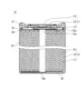
- FIG. 1 is a longitudinal cross-sectional view of a non-aqueous electrolyte secondary battery according to an embodiment of the present disclosure. It is a figure which shows the charging curve of the battery of reference example R1 using the negative electrode which does not contain a 2nd material. It is a figure which shows the charging curve of the battery of reference example R2 in which the negative electrode of R1 was replaced with lithium metal.
- FIG. 3 is a diagram showing the polarization behavior of graphite.
- FIG. 3 is a diagram showing polarization behavior of a first material containing silicon.
- FIG. 3 is a diagram showing polarization behavior of a first material containing silicon.
- FIG. 3 is a diagram showing polarization behavior of a first material containing silicon.
- FIG. 3 is a diagram showing polarization behavior of a first material containing silicon.
- FIG. 3 is a diagram showing polarization behavior of a first material containing silicon.
- FIG. 3 is a diagram showing polarization behavior of a first material containing silicon. It is a figure showing the charge curve of the negative electrode containing the 1st material and the 2nd material. 5 is an enlarged view of the curve at the end of charging in FIG. 4.
- FIG. FIG. 6 is a diagram showing the relationship between the SOC of the test cell and the content of the second material in the negative electrode mixture layer when the closed circuit potential of the negative electrode reaches the potential of lithium metal.
- non-aqueous electrolyte secondary battery may be liquid, gel, or solid unless inconsistent with the spirit of the invention. It broadly covers secondary batteries equipped with a non-aqueous electrolyte.
- the present invention can also be applied to all-solid-state secondary batteries.
- a non-aqueous electrolyte secondary battery generally includes an electrode group, a non-aqueous electrolyte, and a battery case that houses the electrode group and the non-aqueous electrolyte.
- the electrode group includes a positive electrode, a negative electrode, and a separator disposed between the positive electrode and the negative electrode.
- the negative electrode according to this embodiment has a negative electrode mixture layer containing a negative electrode active material.
- the negative electrode mixture layer is provided, for example, on the surface of a sheet-like negative electrode current collector. Since the negative electrode mixture layer is composed of a negative electrode mixture containing a negative electrode active material as a main component, it may also be referred to as a negative electrode active material layer.
- the negative electrode mixture is a mixture containing a negative electrode active material as a main component, and may contain a binder, a conductive agent, and the like as optional components.
- the negative electrode active material includes at least a first material and a second material. Both the first material and the second material are active materials that develop capacity through a faradaic reaction. That is, the first material and the second material are active materials that intercalate and deintercalate (or intercalate and deintercalate) lithium ions along with battery reactions. However, the entire first material does not need to be an active material, and it is sufficient that at least a portion of the first material is made of an active material. Furthermore, the entire second material does not need to be an active material, and it is sufficient that at least a portion of the second material is made of an active material.
- the first material may include silicon that reacts with Li to form an alloy. The surface of silicon may be oxidized, for example, may have a natural oxide film.
- the second material may include an active material that has a higher reaction potential with Li than silicon.
- the reaction potential of the second material with Li is higher than that of the first material.
- the negative electrode potential becomes a hybrid potential influenced by at least the potential of the first material and the potential of the second material.
- Such a hybrid potential will be higher than the potential of the first material.
- the phenomenon in which the negative electrode potential becomes excessively low at an early stage and reaches the end-of-charge voltage earlier than expected becomes apparent when the content of the first material in the negative electrode mixture layer is considerably increased. Specifically, such a phenomenon becomes apparent when the silicon content Cs in the negative electrode mixture layer is 10% by mass or more. Conventionally, in batteries that have been put into practical use, such a phenomenon did not become apparent because the silicon content Cs in the negative electrode mixture layer was small.
- the silicon content Cs in the negative electrode mixture layer 10% by mass or more, 12% by mass or more, and even more. is desirably 20% by mass or more.
- increasing the average potential of the negative electrode using the second material is effective in increasing the positive electrode potential when the battery voltage reaches the end-of-charge voltage.
- the end-of-charge voltage corresponds to the voltage of a fully charged battery (closed circuit voltage).
- the end-of-discharge voltage corresponds to the voltage of the battery in a fully discharged state (closed circuit voltage).
- Charging and discharging of the non-aqueous electrolyte secondary battery is controlled by a predetermined control circuit.
- Such a control circuit is controlled to stop charging when a preset end-of-charge voltage (for example, 4.2V) is reached.
- a preset end-of-charge voltage for example, 4.2V
- the second material is a material that does not contain silicon, which contributes to charging and discharging, and does not contribute to increasing the capacity of the negative electrode, unlike the first material containing silicon (or silicon phase). Therefore, it is desirable to use the second material in an amount that does not impair the effect of increasing the capacity provided by the first material. From the viewpoint of enhancing the effect of increasing capacity, it is desirable that the content C1 of the first material in the negative electrode mixture layer is larger than the content C2 of the second material in the negative electrode mixture layer. Specifically, the content C2 may be 0.5 times or less the content C1 (C2/C1 ⁇ 0.5).
- the silicon content Cs in the negative electrode mixture layer may be greater than the content C2.
- the content Cs may be at least 1.5 times the content C2 (Cs/C2 ⁇ 1.5), or at least twice the content C2 (Cs/C2 ⁇ 2).
- the silicon content Cs may be limited to 30% by mass or less.
- the content C2 of the second material in the negative electrode mixture layer is not particularly limited, and if even a small amount of the second material is contained in the negative electrode mixture layer, a mixed potential is formed accordingly, and the The effect of suppressing deterioration of the negative electrode battery can be obtained.
- the content C2 is desirably 0.5% by mass or more, may be 3% by mass or more, may be 5% by mass or more, or 10% by mass or more.
- the content C2 since the second material does not contribute to increasing the capacity as much as the first material, the content C2 may be, for example, 15% by mass or less, or 10% by mass or less.
- the first material may include silicon, may be substantially composed only of silicon (or a silicon phase), or may be composite particles containing a material other than silicon.
- the first material may be used alone or in combination of two or more.
- the first material may be a composite particle containing a silicon phase and a matrix phase in which the silicon phase is dispersed.
- the matrix phase may be made of a material having lithium ion conductivity.
- the matrix phase includes, for example, at least one selected from the group consisting of a silicon oxide phase and a carbon phase.
- the silicon oxide phase contains Si and O, and may further contain a third element other than Si and O.
- the silicon oxide phase may be composed of SiO2 , lithium silicate, or both.
- composite particles that are the first material may have any of the forms (a) to (c) below, for example.
- a first composite particle including a silicon phase and a silicon dioxide (SiO 2 ) phase in which the silicon phase is dispersed.
- the first, second, and third composite particles all include a silicone phase dispersed in the matrix phase, and may also include a second material dispersed in the matrix phase. That is, the first material and the second material may be composited to form any composite particles.
- the first material is composed of only a silicon phase, and the entire first material may be considered as an active material (silicon phase).
- the negative electrode mixture layer may have any of the following forms (A) to (C), for example.
- a negative electrode mixture layer containing a mixture of particles of a first material and particles of a second material.
- a negative electrode mixture layer containing composite particles in which the first material and the second material are composited into particles (for example, the first, second, and third composite particles described above).
- Composite particles in which a first material and a second material are composited into particles for example, the first, second, and third composite particles described above
- a third material other than such composite particles for example, carbonaceous particles such as graphite, non-graphitizable carbon, and easily graphitizable carbon
- the first composite particles are superior among the first materials in that they have high stability and small volume change. ing.
- the high stability is thought to be due to the small particle size of the silicon phase (or silicon particles) dispersed in the silicon dioxide phase, making it difficult for deep charging to proceed.
- the silicon dioxide phase has a relatively large number of sites that irreversibly trap lithium ions, so it tends to have a large irreversible capacity among the first materials, but it also has high structural stability and suppresses volume changes. Cheap.
- the first composite particles can be synthesized, for example, by heating the raw material silicon oxide and performing a disproportionation reaction in a non-oxidizing atmosphere.
- silicon fine particles can be produced uniformly in the silicon dioxide phase.
- the average particle size of silicon fine particles produced by the disproportionation reaction is, for example, less than 100 nm, and may be from 5 nm to 50 nm.
- the matrix phase of the first composite particles may be composed of, for example, 95 to 100% by weight of silicon dioxide.
- the overall composition of the first composite particles can be expressed by the general formula SiO x (0 ⁇ x ⁇ 2).
- the content of the silicon phase contained in the first composite particles may be, for example, 20% by mass to 60% by mass.
- the second composite particles (including a lithium silicate phase and a silicon phase dispersed in the lithium silicate phase) are superior among the first materials in that they have a small irreversible capacity.
- excellent charge and discharge efficiency can be obtained. This effect is particularly noticeable in the early stages of charging and discharging.
- the lithium silicate phase may also contain at least one element selected from the group consisting of Group 1 elements (other than Li) and Group 2 elements of the long periodic table as a third element. good.
- Group 1 elements and Group 2 elements can be, for example, K, Na, Mg, Ca, Sr, Ba, and the like.
- the lithium silicate phase may further include Al, B, La, P, Zr, Ti, Fe, Cr, Ni, Mn, Cu, Mo, Zn, and the like.
- the ratio of the number of O atoms to the number of Si atoms (O/Si) in the lithium silicate phase is, for example, greater than 2 and less than 4. This case is advantageous in terms of stability and lithium ion conductivity.
- the O/Si ratio may be greater than 2 and less than 3.
- the ratio of the number of Li atoms to the number of Si atoms (Li/Si) in the lithium silicate phase is, for example, greater than 0 and less than 4.
- the second composite particles can be obtained, for example, by mixing lithium silicate and raw silicon, stirring the mixture while crushing it with a stirrer such as a ball mill, and then firing the mixture in an inert atmosphere. Sinter the mixture and crush the sintered body. It may also be used as a second composite particle.
- the content of the silicon phase contained in the second composite particles may be, for example, 35% by mass or more and 80% by mass or less. Since the content of the silicon phase in the second composite particles can be arbitrarily changed, it is easy to design a high capacity negative electrode.
- the third composite particles are superior among the first materials in that they have a small irreversible capacity. Further, since the carbon phase can develop capacity through a faradaic reaction with lithium ions, it is advantageous among the first materials for increasing capacity.
- the carbon phase may contain crystalline carbon (graphite) or may contain amorphous carbon with low crystallinity (i.e. amorphous carbon).
- the amorphous carbon may be, for example, non-graphitizable carbon, easily graphitizable carbon, or other materials.
- the third composite particles can be obtained, for example, by mixing the carbon source and raw material silicon, stirring the mixture while crushing it with a stirrer such as a ball mill, and then firing the mixture in an inert atmosphere. Sinter the mixture and crush the sintered body. It may also be used as a third composite particle.
- the carbon source for example, sugars, water-soluble resins, etc. can be used.
- carboxymethylcellulose (CMC), polyvinylpyrrolidone, cellulose, sucrose, etc. may be used as the carbon source.
- the carbon source and raw material silicon may be dispersed in a dispersion medium of a liquid organic substance such as alcohol.
- the content of the silicon phase contained in the third composite particles may be, for example, 40% by mass or more and 80% by mass or less. Since the content of the silicon phase in the third composite particles can be arbitrarily changed, it is easy to design a high capacity negative electrode.
- the average particle size of the silicon phase (or silicon particles) in the second or third composite particles is, for example, 100 nm or more and 500 nm or less, may be 400 nm or less, or may be 200 nm or less. Since the silicon phase has such a large average particle size, it becomes easier to increase the capacity of these composite particles.
- the silicon phase dispersed within the matrix phase of the second composite particle or the third composite particle may be composed of a plurality of crystallites.
- the crystallite size may be, for example, 30 nm or less, or 25 nm or less. In this case, volume changes due to expansion and contraction of the silicon phase during charging and discharging can be minimized.
- the crystallite size is not particularly limited, but may be, for example, 5 ⁇ m or more, or 10 nm or more.
- the crystallite size of the silicon phase is calculated from the half-width of the diffraction peak attributed to the Si (111) plane of the X-ray diffraction (XRD) pattern of the silicon phase using the Scherrer equation.
- the average particle diameter of the first, second, and third composite materials may be, for example, 2 ⁇ m to 10 ⁇ m, or 4 ⁇ m to 7 ⁇ m. This makes it easier to relieve stress caused by changes in the volume of the silicon phase due to charging and discharging.
- the average particle size means a particle size (volume average particle size) at which the volume integrated value is 50% in a particle size distribution measured, for example, by a laser diffraction scattering method.
- the measuring device for example, "LA-750" manufactured by Horiba, Ltd. (HORIBA) can be used.
- the content of the silicon phase in the first, second, and third composite materials can be measured by, for example, Si-NMR.
- the average particle size of the silicon phase in the first, second, and third composite materials can be measured from a cross-sectional SEM (scanning electron microscope) photograph of the composite particles. Specifically, the average particle size of the silicon phase is determined by averaging the maximum diameter of 100 arbitrary silicon particles.
- the second material may include an active material that has a higher reaction potential with Li than with silicon.
- the reaction potential of the second material with Li is 0.5 V or more higher than the potential of lithium metal.
- Such a second material is usually other than a carbonaceous material, for example a metal compound is a likely candidate.
- the second material may be used alone or in combination of two or more.
- the metal compound that can be used as the second material may have a crystal structure such as a spinel structure, a perovskite structure, or a layered rock salt structure.
- a crystal structure such as a spinel structure, a perovskite structure, or a layered rock salt structure.
- lithium-titanium composite oxides and lithium-manganese composite oxides having a spinel-type structure, lithium-containing transition metal oxides with a layered rock-salt type structure known as positive electrode active materials for lithium ion secondary batteries, etc. may be used. good.
- lithium titanium composite oxide has a reaction potential with Li of about 1.5V to 1.6V relative to the potential of lithium metal, and exhibits excellent performance as a negative electrode active material for nonaqueous electrolyte secondary batteries. This is preferable in this respect.
- a lithium titanium composite oxide having a spinel-type crystal structure is represented by, for example, the general formula Li 4+z Ti 5 O 12 (0 ⁇ z ⁇ 1).
- Lithium titanium composite oxide is excellent in that it has a high acceptability of lithium ions and can easily reduce the diffusion resistance of ions in the negative electrode.
- the most typical material is Li 4 Ti 5 O 12 .
- Li v Ti 5-w M w O 12+t 3 ⁇ v ⁇ 5, 0.005 ⁇ w ⁇ 1.5, -1 ⁇ t ⁇ 1) is used, good.
- M is, for example, from the group consisting of V, Mn, Fe, Co, Ni, Cu, Zn, Al, B, Mg, Ca, Sr, Ba, Zr, Nb, Mo, W, Bi, Na, K and rare earth elements. At least one selected type.
- the average particle size of the lithium titanium composite oxide is, for example, 20 ⁇ m or less, and may be 10 ⁇ m or less, from the viewpoint of ensuring dispersibility within the negative electrode mixture layer and forming a uniform hybrid potential.
- the average particle size of the lithium titanium composite oxide may be, for example, 0.4 ⁇ m or more, or 0.6 ⁇ m or more.
- the average particle size also means the volume average particle size of 50% of the volume integrated value in the particle size distribution measured, for example, by a laser diffraction scattering method.
- the negative electrode active material may further include carbonaceous particles.
- Carbonaceous particles have a smaller degree of expansion and contraction during charging and discharging than the first material, and therefore can easily improve cycle characteristics. Furthermore, carbonaceous particles have a lower reaction potential with Li than the second material, and are advantageous for increasing capacity.
- the content of carbonaceous particles (excluding the carbon phase as the matrix phase of the first material) in the negative electrode active material may be, for example, 70% by mass to 90% by mass. This makes it easier to achieve both high capacity and cycle characteristics.
- Examples of the carbonaceous particles include graphite, graphitizable carbon (soft carbon), non-graphitizable carbon (hard carbon), and the like. Among these, graphite is preferable because it has excellent charging/discharging stability and low irreversible capacity.
- Graphite means a material having a graphite-type crystal structure, and includes, for example, natural graphite, artificial graphite, graphitized mesophase carbon particles, and the like. One type of carbon material may be used alone, or two or more types may be used in combination.
- a lithium ion secondary battery which is an example of a nonaqueous electrolyte secondary battery according to an embodiment of the present disclosure, will be outlined.
- a lithium ion secondary battery includes, for example, the following negative electrode, positive electrode, and nonaqueous electrolyte.
- the negative electrode includes a negative electrode current collector and a negative electrode mixture layer.
- the negative electrode mixture layer is formed, for example, by applying a negative electrode slurry in which a negative electrode mixture containing a negative electrode active material is dispersed in a dispersion medium to the surface of a negative electrode current collector, and rolling the dried coating film.
- the negative electrode mixture layer may be formed on one surface or both surfaces of the negative electrode current collector.
- the negative electrode mixture contains a negative electrode active material as an essential component, and a binder, a conductive agent, a thickener, etc. as optional components.
- the negative electrode current collector is in the form of a sheet, and metal foil, mesh, net, punched sheet, etc. are used.
- Examples of the material of the negative electrode current collector include stainless steel, nickel, nickel alloy, copper, and copper alloy.
- the thickness of the negative electrode current collector is not particularly limited, but is, for example, 1 ⁇ m to 50 ⁇ m, and may be 5 ⁇ m to 20 ⁇ m.
- a resin material is used as the binder.
- examples include fluororesins, polyolefin resins, polyamide resins, polyimide resins, acrylic resins, vinyl resins, and rubber-like materials.
- Examples of the conductive agent include carbon black and carbon nanotubes.
- thickener examples include carboxymethyl cellulose (CMC), modified products of CMC (Na salt, etc.), cellulose derivatives, polyvinyl alcohol, polyether, and the like.
- dispersion medium examples include water, alcohol, ether, and N-methyl-2-pyrrolidone (NMP).
- the positive electrode includes a positive electrode active material that can electrochemically insert and release lithium ions.
- the positive electrode includes, for example, a positive electrode current collector and a positive electrode mixture layer.
- the positive electrode mixture layer is formed, for example, by applying a positive electrode slurry in which a positive electrode mixture containing a positive electrode active material is dispersed in a dispersion medium onto the surface of a positive electrode current collector, and rolling the dried coating film.
- the positive electrode mixture layer may be formed on one surface or both surfaces of the positive electrode current collector.
- the positive electrode mixture contains a positive electrode active material as an essential component, and a binder, a conductive agent, etc. as optional components.
- a lithium-containing transition metal oxide can be used as the positive electrode active material.
- a lithium-containing transition metal oxide can be used as the positive electrode active material.
- M is Na, Mg, Sc, Y, Mn, Fe, Co, Ni, Cu, Zn, at least one selected from the group consisting of Al, Cr, Pb, Sb, and B.
- a 0 to 1.2
- b 0 to 0.9
- c 2.0 to 2.3. Note that the a value indicating the molar ratio of lithium increases or decreases due to charging and discharging.
- any of the materials exemplified for the negative electrode can be used.
- Graphite such as natural graphite or artificial graphite may be used as the conductive agent.
- the positive electrode current collector is in the form of a sheet, and metal foil, mesh, net, punched sheet, etc. are used.
- Examples of the material of the positive electrode current collector include stainless steel, aluminum, aluminum alloy, and titanium.
- the thickness of the positive electrode current collector is not particularly limited, but is, for example, 1 ⁇ m to 50 ⁇ m, and may be 5 ⁇ m to 20 ⁇ m.
- the nonaqueous electrolyte may be a liquid electrolyte (electrolytic solution), a gel electrolyte, or a solid electrolyte.
- the gel electrolyte contains a lithium salt and a matrix polymer, or alternatively contains a lithium salt, a nonaqueous solvent, and a matrix polymer.
- the matrix polymer for example, a polymer material that absorbs a non-aqueous solvent and gels is used. Examples of the polymer material include fluororesin, acrylic resin, polyether resin, polyethylene oxide, and the like.
- the solid electrolyte may be an inorganic solid electrolyte.
- inorganic solid electrolyte for example, materials known for use in all-solid lithium ion secondary batteries and the like (eg, oxide-based solid electrolytes, sulfide-based solid electrolytes, halide-based solid electrolytes, etc.) are used.
- the liquid electrolyte includes, for example, a nonaqueous solvent and an electrolyte salt.
- the electrolyte salt includes at least a lithium salt.
- the lithium salt concentration in the non-aqueous electrolyte is preferably 0.5 mol/L or more and 2 mol/L or less, for example.
- non-aqueous solvent for example, a cyclic carbonate, a chain carbonate, a cyclic carboxylic acid ester, a chain carboxylic ester, etc. are used.
- lithium salts examples include LiClO 4 , LiBF 4 , LiPF 6 , LiAlCl 4 , LiSbF 6 , LiSCN, LiCF 3 SO 3 , LiCF 3 CO 2 , LiAsF 6 , and imide salts.
- imide salts examples include lithium bisfluorosulfonylimide (LiN(FSO 2 ) 2 ), lithium bistrifluoromethanesulfonate imide (LiN(CF 3 SO 2 ) 2 ), and the like.
- a separator may be interposed between the positive electrode and the negative electrode.
- the separator has high ion permeability, appropriate mechanical strength, and insulation properties.
- a microporous membrane, woven fabric, nonwoven fabric, etc. can be used as the separator.
- the material of the separator includes, for example, polyolefin such as polypropylene and polyethylene.
- a lithium ion secondary battery may have any shape, such as a cylindrical shape, a square shape, a coin shape, a button shape, and a laminate shape.
- the structure of a cylindrical lithium ion secondary battery (secondary battery 10) will be described below with reference to FIG. 1.
- the secondary battery 10 includes an electrode group 18, an electrolyte (not shown), and a bottomed cylindrical battery can 22 that accommodates these.
- the sealing body 11 is caulked and fixed to the opening of the battery can 22 with a gasket 21 interposed therebetween. This seals the inside of the battery.
- the sealing body 11 includes a valve body 12, a metal plate 13, and an annular insulating member 14 interposed between the valve body 12 and the metal plate 13.
- the valve body 12 and the metal plate 13 are connected to each other at their respective centers.
- a positive electrode lead 15a led out from the positive electrode 15 is connected to the metal plate 13. Therefore, the valve body 12 functions as a positive external terminal.
- a negative electrode lead 16a led out from the negative electrode 16 is connected to the bottom inner surface of the battery can 22.
- An annular groove 22a is formed near the open end of the battery can 22.
- a first insulating plate 23 is arranged between one end surface of the electrode group 18 and the annular groove 22a.
- a second insulating plate 24 is arranged between the other end surface of the electrode group 18 and the bottom of the battery can 22.
- the electrode group 18 is formed by winding a strip-shaped positive electrode 15 and a strip-shaped negative electrode 16 with a separator 17 in between.
- Second composite particles (average particle diameter 8 ⁇ m, silicon content 55% by mass) and third composite particles (average particle diameter 7 ⁇ m, silicon content 58% by mass) were prepared.
- the second composite particles were mixed with coal pitch, the mixture was fired at 800°C in an inert atmosphere, the surface of the second composite particles was coated with conductive carbon, and the average particle size was controlled by subsequent crushing conditions. .
- the thickness of the conductive layer is estimated to be approximately 100 nm.
- the average grain size of the silicon phase was about 100 nm, and the crystallite size of the silicon phase was 15 nm.
- the third composite material includes an amorphous carbon phase and a silicon phase dispersed within the amorphous carbon phase.
- the average grain size of the silicon phase was about 200 nm, and the crystallite size was 15 nm.
- ⁇ Negative electrode active material> The second composite particles, the third composite particles, and graphite were mixed at a mass ratio of 3:32:65 to prepare a negative electrode active material.
- a negative electrode mixture containing a negative electrode active material, CMC Na salt, and styrene butadiene rubber (SBR) in a mass ratio of 97.5:1:1.5 is dispersed in water as a dispersion medium and mixed.
- a negative electrode slurry was prepared by stirring using a machine.
- the silicon content Cs in the negative electrode mixture (that is, the negative electrode mixture layer to be formed later) is 19.7% by mass, and the content C1 of the first material (the total amount of the first composite particles and the second composite particles) is It was 34.1% by mass.
- the negative electrode slurry was applied to both sides of the copper foil, and the coating film was dried and then rolled to form a negative electrode mixture layer on both sides of the copper foil, thereby obtaining a negative electrode.
- Lithium nickel composite oxide LiNi 0.8 Co 0.18 Al 0.02 O 2
- acetylene black and polyvinylidene fluoride were mixed at a mass ratio of 95:2.5:2.5, and NMP and stirred using a mixer to prepare a positive electrode slurry.
- the positive electrode slurry was applied to both sides of an aluminum foil, and the coated film was dried and then rolled to form a positive electrode mixture layer on both sides of the aluminum foil, thereby obtaining a positive electrode.
- a non-aqueous electrolyte was prepared by dissolving a lithium salt in a non-aqueous solvent.
- a mixed solvent containing ethylene carbonate (EC) and dimethyl carbonate (DMC) at a volume ratio of 30:70 was used as the nonaqueous solvent.
- LiPF 6 was used as the lithium salt. The LiPF 6 concentration was 1.1 mol/L.
- An electrode group was prepared by attaching a tab to each electrode and spirally winding the positive electrode and negative electrode with a separator in between so that the tab was located at the outermost periphery. After inserting the electrode group into an aluminum laminate film exterior body and vacuum drying at 60°C for 12 hours, a non-aqueous electrolyte was injected and the opening of the exterior body was sealed to obtain battery R1 of Reference Example 1. Ta.
- the battery R1 of Reference Example R1 produced above was subjected to predetermined preliminary charging and discharging twice, and then charged in the following manner.
- Battery R1 is charged at an ambient temperature of 25°C with a current of 0.1C until the battery voltage reaches 4.2V, and then with a constant voltage of 4.2V until the current reaches 0.02C. Voltage charged.
- the charging curve at this time is shown in FIG. 2A.
- FIG. 2B at the end of charging, a voltage increase behavior corresponding to the structural change of the positive electrode active material is observed, whereas in FIG. 2A, this is not observed. From this, it can be understood that the battery voltage quickly reached 4.2 V at the end of charging, and the positive electrode potential did not rise as much as expected.
- C(Ah)/X(h) represents the current value when charging or discharging the amount of electricity for the rated capacity over X hours.
- ⁇ Reference example C1 ⁇ [Preparation of negative electrode] A negative electrode slurry was prepared in the same manner as Reference Example R1, except that only graphite was used as the negative electrode active material, and the negative electrode slurry was applied to both sides of a copper foil. After drying, the coating film was rolled to form a copper foil. A negative electrode mixture layer was formed on both sides to obtain a negative electrode.
- the negative electrode was cut into a 20 mm x 20 mm shape with a 5 mm x 5 mm protrusion, and the negative electrode mixture layer on the protrusion was peeled off to expose the copper foil. Thereafter, a negative electrode tab lead was connected to the exposed portion of the negative electrode current collector, and a predetermined area on the outer periphery of the negative electrode tab lead was covered with an insulating film.
- a tab was prepared by welding a small piece of Ni mesh to the end, cut into a predetermined size, and the mesh portion was pressed against a 300 ⁇ m thick lithium metal foil to prepare a counter electrode.
- a negative electrode regulated cell was produced using the above negative electrode and two counter electrodes.
- An electrode group was obtained by sandwiching the negative electrode between a pair of counter electrodes and making the negative electrode mixture layer and lithium metal foil face each other with a separator in between.
- the Al laminate film cut into a rectangle was folded in half, and the two long side ends were heat-sealed to form a cylindrical shape.
- the produced electrode group was placed into a cylinder from one of the short sides, and the end face of the Al laminate film and the insulating film of each tab lead were aligned and heat-sealed.
- a negative electrode slurry was prepared in the same manner as Reference Example R1, except that the second composite particles and graphite were mixed at a mass ratio of 20:80 to prepare a negative electrode active material. After drying the coating film, it was rolled to form a negative electrode mixture layer on both sides of the copper foil to obtain a negative electrode. Then, a test cell E1 was prepared and evaluated in the same manner as Reference Example C1.
- ⁇ Reference example E2 ⁇ A negative electrode slurry was prepared in the same manner as Reference Example R1, except that the third composite particles and graphite were mixed at a mass ratio of 20:80 to prepare a negative electrode active material. After drying the coating film, it was rolled to form a negative electrode mixture layer on both sides of the copper foil to obtain a negative electrode. Then, a test cell E2 was prepared and evaluated in the same manner as Reference Example C1.
- a negative electrode slurry was prepared in the same manner as Reference Example R1, except that the second composite particles, the third composite particles, and graphite were mixed at a mass ratio of 5:25:70 to prepare a negative electrode active material.
- the negative electrode slurry was applied to both sides of the copper foil, and after drying, the coating film was rolled to form a negative electrode mixture layer on both sides of the copper foil, thereby obtaining a negative electrode.
- test cell E3 was produced and evaluated in the same manner as Reference Example C1.
- ⁇ Reference example E4 ⁇ A negative electrode slurry was prepared in the same manner as Reference Example R1, except that the second composite particles and graphite were mixed at a mass ratio of 30:70 to prepare a negative electrode active material. After drying the coating film, it was rolled to form a negative electrode mixture layer on both sides of the copper foil to obtain a negative electrode. Then, test cell E4 was produced and evaluated in the same manner as Reference Example C1.
- ⁇ Reference example E5 ⁇ A negative electrode slurry was prepared in the same manner as Reference Example R1, except that the third composite particles and graphite were mixed at a mass ratio of 30:70 to prepare a negative electrode active material. After drying the coating film, it was rolled to form a negative electrode mixture layer on both sides of the copper foil to obtain a negative electrode. Then, test cell E5 was produced and evaluated in the same manner as Reference Example C1.
- FIG. 3A shows charging curves for cell C1
- FIGS. 3B to 3F show charging curves for E1 to E5.
- 3A to 3E it can be seen that in the cell C1 of Reference Example 2, the polarization of the negative electrode is small, and the negative electrode potential (closed circuit potential) at full charge is higher than the potential of lithium metal.
- the polarization of the negative electrode is large, and the negative electrode potential (closed circuit potential) at the time of full charge is lower than the potential of lithium metal.
- a negative electrode active material was prepared by mixing the second composite particles, the third composite particles, graphite, and the second material (Li 4 Ti 5 O 12 ) at a mass ratio of 3:32:65:3. Except for this, prepare a negative electrode slurry in the same manner as Reference Example R1, apply the negative electrode slurry to both sides of a copper foil, dry the coating film, and then roll it to form a negative electrode mixture layer on both sides of the copper foil, Obtained a negative electrode.
- the silicon content Cs in the negative electrode mixture (that is, the negative electrode mixture layer) is 19.1% by mass, and the content C1 of the first material (the total amount of the first composite particles and the second composite particles) is 33.1 mass%. %, and the content C2 of the second material was 3% by mass. Then, a test cell A1 was prepared and evaluated in the same manner as Reference Example C1.
- a negative electrode active material was prepared by mixing the second composite particles, the third composite particles, graphite, and the second material (Li 4 Ti 5 O 12 ) at a mass ratio of 3:32:65:5. Except for this, prepare a negative electrode slurry in the same manner as Reference Example R1, apply the negative electrode slurry to both sides of a copper foil, dry the coating film, and then roll it to form a negative electrode mixture layer on both sides of the copper foil, Obtained a negative electrode.
- test cell A2 was produced and evaluated in the same manner as Reference Example C1.
- a negative electrode active material was prepared by mixing the second composite particles, the third composite particles, graphite, and the second material (Li 4 Ti 5 O 12 ) at a mass ratio of 3:32:65:10. Except for this, prepare a negative electrode slurry in the same manner as Reference Example R1, apply the negative electrode slurry to both sides of a copper foil, dry the coating film, and then roll it to form a negative electrode mixture layer on both sides of the copper foil, Obtained a negative electrode.
- test cell A3 was produced and evaluated in the same manner as Reference Example C1.
- a negative electrode active material was prepared by mixing the second composite particles, the third composite particles, graphite, and the second material (Li 4 Ti 5 O 12 ) at a mass ratio of 3:32:65:15. Except for this, prepare a negative electrode slurry in the same manner as Reference Example R1, apply the negative electrode slurry to both sides of a copper foil, dry the coating film, and then roll it to form a negative electrode mixture layer on both sides of the copper foil, Obtained a negative electrode.
- test cell A4 was produced and evaluated in the same manner as Reference Example C1.
- a negative electrode active material was prepared by mixing the second composite particles, the third composite particles, and graphite at a mass ratio of 3:32:65 without using the second material (Li 4 Ti 5 O 12 ).
- a negative electrode slurry was prepared in the same manner as Reference Example R1, the negative electrode slurry was applied to both sides of a copper foil, and after drying the coating film, it was rolled to form a negative electrode mixture layer on both sides of the copper foil. , a negative electrode was obtained.
- test cell A5 was produced and evaluated in the same manner as Reference Example C1.
- FIG. 4 shows the charging curves of cells A1 to A5.
- the solid line curve is the curve of cell A5 not using the second material, and the higher the SOC at the end of charging, the higher the content of the second material. That is, the curves belong to cells A1 to A4 in order from the left side to the right side.
- FIG. 5 shows an enlarged view of FIG. 4 at the end of charging.
- Figure 6 also shows the SOC (negative potential rush SOC (%)) of the test cell when the closed circuit potential of the negative electrode reaches the potential of lithium metal and the content rate of the second material in the negative electrode mixture layer (additional (%)).
- the SOC of the test cell when the closed circuit potential of the negative electrode reaches the potential of lithium metal changes depending on the content C2 of the second material in the negative electrode mixture layer. Furthermore, it can be understood that the larger the content C2, the greater the effect of increasing the negative electrode potential at the end of charging during charging.
- a non-aqueous electrolyte secondary battery including a negative electrode for a non-aqueous electrolyte secondary battery according to the present disclosure is suitable for main power sources for mobile communication devices, portable electronic devices, etc., automotive power sources, etc.; It is not limited.
Landscapes
- Chemical & Material Sciences (AREA)
- Chemical Kinetics & Catalysis (AREA)
- Electrochemistry (AREA)
- General Chemical & Material Sciences (AREA)
- Inorganic Chemistry (AREA)
- Composite Materials (AREA)
- Engineering & Computer Science (AREA)
- Materials Engineering (AREA)
- Crystallography & Structural Chemistry (AREA)
- Battery Electrode And Active Subsutance (AREA)
Priority Applications (4)
| Application Number | Priority Date | Filing Date | Title |
|---|---|---|---|
| JP2024509975A JPWO2023181949A1 (https=) | 2022-03-25 | 2023-03-08 | |
| CN202380029789.0A CN118974965A (zh) | 2022-03-25 | 2023-03-08 | 非水电解质二次电池用负极及非水电解质二次电池 |
| US18/849,704 US20250210623A1 (en) | 2022-03-25 | 2023-03-08 | Negative electrode for non-aqueous electrolyte secondary battery, and non-aqueous electrolyte secondary battery |
| EP23774548.4A EP4503175A4 (en) | 2022-03-25 | 2023-03-08 | NEGATIVE ELECTRODE FOR SECONDARY BATTERY WITH NON-AQUEOUS ELECTROLYTE, AND SECONDARY BATTERY WITH NON-AQUEOUS ELECTROLYTE |
Applications Claiming Priority (2)
| Application Number | Priority Date | Filing Date | Title |
|---|---|---|---|
| JP2022050391 | 2022-03-25 | ||
| JP2022-050391 | 2022-03-25 |
Publications (1)
| Publication Number | Publication Date |
|---|---|
| WO2023181949A1 true WO2023181949A1 (ja) | 2023-09-28 |
Family
ID=88100765
Family Applications (1)
| Application Number | Title | Priority Date | Filing Date |
|---|---|---|---|
| PCT/JP2023/008861 Ceased WO2023181949A1 (ja) | 2022-03-25 | 2023-03-08 | 非水電解質二次電池用負極および非水電解質二次電池 |
Country Status (5)
| Country | Link |
|---|---|
| US (1) | US20250210623A1 (https=) |
| EP (1) | EP4503175A4 (https=) |
| JP (1) | JPWO2023181949A1 (https=) |
| CN (1) | CN118974965A (https=) |
| WO (1) | WO2023181949A1 (https=) |
Citations (7)
| Publication number | Priority date | Publication date | Assignee | Title |
|---|---|---|---|---|
| JP2013101931A (ja) * | 2011-11-08 | 2013-05-23 | Samsung Sdi Co Ltd | 負極活物質、その製造方法、該活物質を含む電極及び該電極を採用したリチウム電池 |
| WO2013099279A1 (ja) * | 2011-12-28 | 2013-07-04 | パナソニック株式会社 | 非水電解質二次電池用負極および非水電解質二次電池用負極を有する非水電解質二次電池 |
| JP2015125816A (ja) * | 2013-12-25 | 2015-07-06 | 株式会社豊田自動織機 | 複合負極活物質体、非水電解質二次電池用負極および非水電解質二次電池 |
| JP2016081881A (ja) * | 2014-10-22 | 2016-05-16 | トヨタ自動車株式会社 | 非水電解液二次電池 |
| JP2016091649A (ja) | 2014-10-30 | 2016-05-23 | 信越化学工業株式会社 | リチウムイオン二次電池用負極材及びその製造方法、リチウムイオン二次電池用負極並びにリチウムイオン二次電池 |
| JP2018166130A (ja) * | 2018-08-03 | 2018-10-25 | 株式会社Gsユアサ | 非水電解液二次電池 |
| JP2023041247A (ja) * | 2021-09-13 | 2023-03-24 | トヨタ自動車株式会社 | 被覆負極活物質および全固体電池 |
Family Cites Families (3)
| Publication number | Priority date | Publication date | Assignee | Title |
|---|---|---|---|---|
| KR102307911B1 (ko) * | 2017-04-27 | 2021-10-01 | 삼성에스디아이 주식회사 | 리튬이차전지용 음극 활물질 및 이를 포함하는 음극을 구비한 리튬이차전지 |
| KR102691451B1 (ko) * | 2018-12-13 | 2024-08-05 | 삼성전자주식회사 | 음극 활물질 및 이를 채용한 리튬 이차 전지, 및 상기 음극 활물질의 제조방법 |
| CN111682183B (zh) * | 2020-06-22 | 2022-10-28 | 贝特瑞新材料集团股份有限公司 | 多元复合负极材料及其制备方法和锂离子电池 |
-
2023
- 2023-03-08 WO PCT/JP2023/008861 patent/WO2023181949A1/ja not_active Ceased
- 2023-03-08 CN CN202380029789.0A patent/CN118974965A/zh active Pending
- 2023-03-08 US US18/849,704 patent/US20250210623A1/en active Pending
- 2023-03-08 EP EP23774548.4A patent/EP4503175A4/en active Pending
- 2023-03-08 JP JP2024509975A patent/JPWO2023181949A1/ja active Pending
Patent Citations (7)
| Publication number | Priority date | Publication date | Assignee | Title |
|---|---|---|---|---|
| JP2013101931A (ja) * | 2011-11-08 | 2013-05-23 | Samsung Sdi Co Ltd | 負極活物質、その製造方法、該活物質を含む電極及び該電極を採用したリチウム電池 |
| WO2013099279A1 (ja) * | 2011-12-28 | 2013-07-04 | パナソニック株式会社 | 非水電解質二次電池用負極および非水電解質二次電池用負極を有する非水電解質二次電池 |
| JP2015125816A (ja) * | 2013-12-25 | 2015-07-06 | 株式会社豊田自動織機 | 複合負極活物質体、非水電解質二次電池用負極および非水電解質二次電池 |
| JP2016081881A (ja) * | 2014-10-22 | 2016-05-16 | トヨタ自動車株式会社 | 非水電解液二次電池 |
| JP2016091649A (ja) | 2014-10-30 | 2016-05-23 | 信越化学工業株式会社 | リチウムイオン二次電池用負極材及びその製造方法、リチウムイオン二次電池用負極並びにリチウムイオン二次電池 |
| JP2018166130A (ja) * | 2018-08-03 | 2018-10-25 | 株式会社Gsユアサ | 非水電解液二次電池 |
| JP2023041247A (ja) * | 2021-09-13 | 2023-03-24 | トヨタ自動車株式会社 | 被覆負極活物質および全固体電池 |
Non-Patent Citations (1)
| Title |
|---|
| See also references of EP4503175A4 |
Also Published As
| Publication number | Publication date |
|---|---|
| US20250210623A1 (en) | 2025-06-26 |
| EP4503175A1 (en) | 2025-02-05 |
| CN118974965A (zh) | 2024-11-15 |
| JPWO2023181949A1 (https=) | 2023-09-28 |
| EP4503175A4 (en) | 2025-12-03 |
Similar Documents
| Publication | Publication Date | Title |
|---|---|---|
| JP5315591B2 (ja) | 正極活物質および電池 | |
| EP2541654B1 (en) | High-capacity positive electrode active material and lithium secondary battery comprising same | |
| US9083062B2 (en) | Battery packs for vehicles and high capacity pouch secondary batteries for incorporation into compact battery packs | |
| KR102321261B1 (ko) | 리튬 이차전지용 음극 활물질 및 이를 포함하는 리튬 이차전지 | |
| CN1988222B (zh) | 阴极活性材料和锂离子二次电池 | |
| JP5882516B2 (ja) | リチウム二次電池 | |
| AU2008349765B2 (en) | Core-shell type anode active material for lithium secondary batteries, method for preparing the same and lithium secondary batteries comprising the same | |
| US10529978B2 (en) | Nonaqueous electrolyte secondary battery | |
| CN113764656A (zh) | 锂二次电池的正极活性物质 | |
| KR101497946B1 (ko) | 코어-쉘 구조의 양극 활물질 및 이의 제조방법 | |
| CN101431151A (zh) | 正极和锂离子二次电池 | |
| KR20130079109A (ko) | 리튬 이차 전지용 양극 활물질 및 이를 포함하는 리튬 이차 전지 | |
| JP4595145B2 (ja) | 非水電解質電池 | |
| JP7771306B2 (ja) | リチウム二次電池の製造方法及びこれにより製造されたリチウム二次電池 | |
| WO2010035681A1 (ja) | 非水電解質二次電池 | |
| KR20090080909A (ko) | 전지 | |
| EP2985824A1 (en) | Cathode material, cathode including the same, and lithium battery including the cathode | |
| JP2004134207A (ja) | 正極活物質及び非水電解質二次電池 | |
| CN117650229A (zh) | 用于锂离子电池的复合阴极 | |
| KR20090084712A (ko) | 비수 전해질 전지 및 정극과 이들의 제조 방법 | |
| JP2008060033A (ja) | 正極活物質、これを用いた正極および非水電解質二次電池、並びに正極活物質の製造方法 | |
| US20220255051A1 (en) | Method of preparing negative electrode active material | |
| JP2005025991A (ja) | 非水電解質二次電池 | |
| JP4656710B2 (ja) | 非水電解液二次電池 | |
| KR20110011497A (ko) | 양극활물질, 이를 포함하는 양극 및 상기 양극을 채용한 리튬전지 |
Legal Events
| Date | Code | Title | Description |
|---|---|---|---|
| 121 | Ep: the epo has been informed by wipo that ep was designated in this application |
Ref document number: 23774548 Country of ref document: EP Kind code of ref document: A1 |
|
| WWE | Wipo information: entry into national phase |
Ref document number: 2024509975 Country of ref document: JP |
|
| WWE | Wipo information: entry into national phase |
Ref document number: 18849704 Country of ref document: US |
|
| WWE | Wipo information: entry into national phase |
Ref document number: 202380029789.0 Country of ref document: CN |
|
| WWE | Wipo information: entry into national phase |
Ref document number: 2023774548 Country of ref document: EP |
|
| NENP | Non-entry into the national phase |
Ref country code: DE |
|
| ENP | Entry into the national phase |
Ref document number: 2023774548 Country of ref document: EP Effective date: 20241025 |
|
| WWP | Wipo information: published in national office |
Ref document number: 18849704 Country of ref document: US |