WO2023181949A1 - 非水電解質二次電池用負極および非水電解質二次電池 - Google Patents
非水電解質二次電池用負極および非水電解質二次電池 Download PDFInfo
- Publication number
- WO2023181949A1 WO2023181949A1 PCT/JP2023/008861 JP2023008861W WO2023181949A1 WO 2023181949 A1 WO2023181949 A1 WO 2023181949A1 JP 2023008861 W JP2023008861 W JP 2023008861W WO 2023181949 A1 WO2023181949 A1 WO 2023181949A1
- Authority
- WO
- WIPO (PCT)
- Prior art keywords
- negative electrode
- silicon
- secondary battery
- electrolyte secondary
- phase
- Prior art date
Links
- 239000011255 nonaqueous electrolyte Substances 0.000 title claims abstract description 46
- 239000000463 material Substances 0.000 claims abstract description 127
- 229910052710 silicon Inorganic materials 0.000 claims abstract description 93
- XUIMIQQOPSSXEZ-UHFFFAOYSA-N Silicon Chemical compound [Si] XUIMIQQOPSSXEZ-UHFFFAOYSA-N 0.000 claims abstract description 92
- 239000010703 silicon Substances 0.000 claims abstract description 91
- 239000000203 mixture Substances 0.000 claims abstract description 86
- 239000007773 negative electrode material Substances 0.000 claims abstract description 33
- 238000006243 chemical reaction Methods 0.000 claims abstract description 12
- OKTJSMMVPCPJKN-UHFFFAOYSA-N Carbon Chemical compound [C] OKTJSMMVPCPJKN-UHFFFAOYSA-N 0.000 claims description 38
- 239000002245 particle Substances 0.000 claims description 37
- VYPSYNLAJGMNEJ-UHFFFAOYSA-N Silicium dioxide Chemical compound O=[Si]=O VYPSYNLAJGMNEJ-UHFFFAOYSA-N 0.000 claims description 23
- 229910052799 carbon Inorganic materials 0.000 claims description 17
- 239000002131 composite material Substances 0.000 claims description 15
- 239000011159 matrix material Substances 0.000 claims description 15
- PAZHGORSDKKUPI-UHFFFAOYSA-N lithium metasilicate Chemical compound [Li+].[Li+].[O-][Si]([O-])=O PAZHGORSDKKUPI-UHFFFAOYSA-N 0.000 claims description 14
- 229910052912 lithium silicate Inorganic materials 0.000 claims description 14
- SWAIALBIBWIKKQ-UHFFFAOYSA-N lithium titanium Chemical compound [Li].[Ti] SWAIALBIBWIKKQ-UHFFFAOYSA-N 0.000 claims description 8
- 229910052814 silicon oxide Inorganic materials 0.000 claims description 7
- 239000011246 composite particle Substances 0.000 description 72
- 238000007600 charging Methods 0.000 description 36
- 239000011267 electrode slurry Substances 0.000 description 24
- RYGMFSIKBFXOCR-UHFFFAOYSA-N Copper Chemical compound [Cu] RYGMFSIKBFXOCR-UHFFFAOYSA-N 0.000 description 22
- 239000011889 copper foil Substances 0.000 description 21
- HBBGRARXTFLTSG-UHFFFAOYSA-N Lithium ion Chemical compound [Li+] HBBGRARXTFLTSG-UHFFFAOYSA-N 0.000 description 19
- 229910002804 graphite Inorganic materials 0.000 description 19
- 239000010439 graphite Substances 0.000 description 19
- 229910052744 lithium Inorganic materials 0.000 description 19
- 229910001416 lithium ion Inorganic materials 0.000 description 19
- 239000011248 coating agent Substances 0.000 description 14
- 238000000576 coating method Methods 0.000 description 14
- 230000001965 increasing effect Effects 0.000 description 14
- 238000012360 testing method Methods 0.000 description 14
- 238000007599 discharging Methods 0.000 description 11
- 230000010287 polarization Effects 0.000 description 11
- PXHVJJICTQNCMI-UHFFFAOYSA-N nickel Substances [Ni] PXHVJJICTQNCMI-UHFFFAOYSA-N 0.000 description 10
- 239000010936 titanium Substances 0.000 description 10
- 239000011149 active material Substances 0.000 description 9
- 238000002156 mixing Methods 0.000 description 9
- 229910052782 aluminium Inorganic materials 0.000 description 8
- 230000000694 effects Effects 0.000 description 8
- 238000002360 preparation method Methods 0.000 description 8
- 239000000377 silicon dioxide Substances 0.000 description 8
- 235000012239 silicon dioxide Nutrition 0.000 description 8
- 238000010586 diagram Methods 0.000 description 7
- 238000001035 drying Methods 0.000 description 7
- 229910003002 lithium salt Inorganic materials 0.000 description 7
- 159000000002 lithium salts Chemical class 0.000 description 7
- 229910052751 metal Inorganic materials 0.000 description 7
- 239000002184 metal Substances 0.000 description 7
- 239000007784 solid electrolyte Substances 0.000 description 7
- WHXSMMKQMYFTQS-UHFFFAOYSA-N Lithium Chemical compound [Li] WHXSMMKQMYFTQS-UHFFFAOYSA-N 0.000 description 6
- SECXISVLQFMRJM-UHFFFAOYSA-N N-Methylpyrrolidone Chemical compound CN1CCCC1=O SECXISVLQFMRJM-UHFFFAOYSA-N 0.000 description 6
- 239000006258 conductive agent Substances 0.000 description 6
- -1 cyclic carboxylic acid ester Chemical class 0.000 description 6
- 239000011888 foil Substances 0.000 description 6
- 239000011572 manganese Substances 0.000 description 6
- 239000007774 positive electrode material Substances 0.000 description 6
- KMTRUDSVKNLOMY-UHFFFAOYSA-N Ethylene carbonate Chemical compound O=C1OCCO1 KMTRUDSVKNLOMY-UHFFFAOYSA-N 0.000 description 5
- 229910013870 LiPF 6 Inorganic materials 0.000 description 5
- 229910003481 amorphous carbon Inorganic materials 0.000 description 5
- 239000011230 binding agent Substances 0.000 description 5
- 239000002612 dispersion medium Substances 0.000 description 5
- 239000003792 electrolyte Substances 0.000 description 5
- 235000002639 sodium chloride Nutrition 0.000 description 5
- 229910004298 SiO 2 Inorganic materials 0.000 description 4
- XAGFODPZIPBFFR-UHFFFAOYSA-N aluminium Chemical compound [Al] XAGFODPZIPBFFR-UHFFFAOYSA-N 0.000 description 4
- 229910052802 copper Inorganic materials 0.000 description 4
- 239000010949 copper Substances 0.000 description 4
- 239000013078 crystal Substances 0.000 description 4
- 230000007423 decrease Effects 0.000 description 4
- 230000002427 irreversible effect Effects 0.000 description 4
- 239000005001 laminate film Substances 0.000 description 4
- 239000007788 liquid Substances 0.000 description 4
- 229910052748 manganese Inorganic materials 0.000 description 4
- 229910052759 nickel Inorganic materials 0.000 description 4
- 239000002994 raw material Substances 0.000 description 4
- 239000011347 resin Substances 0.000 description 4
- 229920005989 resin Polymers 0.000 description 4
- 239000011856 silicon-based particle Substances 0.000 description 4
- 229920002134 Carboxymethyl cellulose Polymers 0.000 description 3
- 239000003125 aqueous solvent Substances 0.000 description 3
- 125000004429 atom Chemical group 0.000 description 3
- 229910052796 boron Inorganic materials 0.000 description 3
- 230000008602 contraction Effects 0.000 description 3
- IEJIGPNLZYLLBP-UHFFFAOYSA-N dimethyl carbonate Chemical compound COC(=O)OC IEJIGPNLZYLLBP-UHFFFAOYSA-N 0.000 description 3
- 238000007323 disproportionation reaction Methods 0.000 description 3
- 230000005611 electricity Effects 0.000 description 3
- JBTWLSYIZRCDFO-UHFFFAOYSA-N ethyl methyl carbonate Chemical compound CCOC(=O)OC JBTWLSYIZRCDFO-UHFFFAOYSA-N 0.000 description 3
- 239000010419 fine particle Substances 0.000 description 3
- 229910021469 graphitizable carbon Inorganic materials 0.000 description 3
- 229910052742 iron Inorganic materials 0.000 description 3
- XEEYBQQBJWHFJM-UHFFFAOYSA-N iron Substances [Fe] XEEYBQQBJWHFJM-UHFFFAOYSA-N 0.000 description 3
- 229910052749 magnesium Inorganic materials 0.000 description 3
- 229910021470 non-graphitizable carbon Inorganic materials 0.000 description 3
- 229910052760 oxygen Inorganic materials 0.000 description 3
- 229920000642 polymer Polymers 0.000 description 3
- 238000007789 sealing Methods 0.000 description 3
- 229910052708 sodium Inorganic materials 0.000 description 3
- 239000002904 solvent Substances 0.000 description 3
- 229910001220 stainless steel Inorganic materials 0.000 description 3
- 239000010935 stainless steel Substances 0.000 description 3
- 238000003756 stirring Methods 0.000 description 3
- XLYOFNOQVPJJNP-UHFFFAOYSA-N water Substances O XLYOFNOQVPJJNP-UHFFFAOYSA-N 0.000 description 3
- 229910052725 zinc Inorganic materials 0.000 description 3
- 229920000178 Acrylic resin Polymers 0.000 description 2
- 239000004925 Acrylic resin Substances 0.000 description 2
- RTZKZFJDLAIYFH-UHFFFAOYSA-N Diethyl ether Chemical compound CCOCC RTZKZFJDLAIYFH-UHFFFAOYSA-N 0.000 description 2
- LFQSCWFLJHTTHZ-UHFFFAOYSA-N Ethanol Chemical compound CCO LFQSCWFLJHTTHZ-UHFFFAOYSA-N 0.000 description 2
- 239000004721 Polyphenylene oxide Substances 0.000 description 2
- FAPWRFPIFSIZLT-UHFFFAOYSA-M Sodium chloride Chemical group [Na+].[Cl-] FAPWRFPIFSIZLT-UHFFFAOYSA-M 0.000 description 2
- 229910052784 alkaline earth metal Inorganic materials 0.000 description 2
- 229910021383 artificial graphite Inorganic materials 0.000 description 2
- 229910052788 barium Inorganic materials 0.000 description 2
- 229910052791 calcium Inorganic materials 0.000 description 2
- 239000003575 carbonaceous material Substances 0.000 description 2
- 229920002678 cellulose Polymers 0.000 description 2
- 239000001913 cellulose Substances 0.000 description 2
- 230000008859 change Effects 0.000 description 2
- 229910052804 chromium Inorganic materials 0.000 description 2
- 230000000052 comparative effect Effects 0.000 description 2
- 238000013461 design Methods 0.000 description 2
- 230000006866 deterioration Effects 0.000 description 2
- 238000009826 distribution Methods 0.000 description 2
- 230000007613 environmental effect Effects 0.000 description 2
- 238000011156 evaluation Methods 0.000 description 2
- 238000010304 firing Methods 0.000 description 2
- 239000000499 gel Substances 0.000 description 2
- 239000011245 gel electrolyte Substances 0.000 description 2
- 229910003480 inorganic solid Inorganic materials 0.000 description 2
- 239000011244 liquid electrolyte Substances 0.000 description 2
- 238000004519 manufacturing process Methods 0.000 description 2
- 150000002736 metal compounds Chemical class 0.000 description 2
- 239000012046 mixed solvent Substances 0.000 description 2
- 238000012986 modification Methods 0.000 description 2
- 230000004048 modification Effects 0.000 description 2
- 229910052750 molybdenum Inorganic materials 0.000 description 2
- 229910021382 natural graphite Inorganic materials 0.000 description 2
- 229920000570 polyether Polymers 0.000 description 2
- 239000002861 polymer material Substances 0.000 description 2
- 229910052700 potassium Inorganic materials 0.000 description 2
- 238000005096 rolling process Methods 0.000 description 2
- 150000003839 salts Chemical class 0.000 description 2
- 238000000790 scattering method Methods 0.000 description 2
- LIVNPJMFVYWSIS-UHFFFAOYSA-N silicon monoxide Chemical compound [Si-]#[O+] LIVNPJMFVYWSIS-UHFFFAOYSA-N 0.000 description 2
- RPACBEVZENYWOL-XFULWGLBSA-M sodium;(2r)-2-[6-(4-chlorophenoxy)hexyl]oxirane-2-carboxylate Chemical compound [Na+].C=1C=C(Cl)C=CC=1OCCCCCC[C@]1(C(=O)[O-])CO1 RPACBEVZENYWOL-XFULWGLBSA-M 0.000 description 2
- 239000007787 solid Substances 0.000 description 2
- 229910052712 strontium Inorganic materials 0.000 description 2
- 239000002562 thickening agent Substances 0.000 description 2
- 229910052719 titanium Inorganic materials 0.000 description 2
- 229910000314 transition metal oxide Inorganic materials 0.000 description 2
- 238000004804 winding Methods 0.000 description 2
- 239000011701 zinc Substances 0.000 description 2
- 229910052726 zirconium Inorganic materials 0.000 description 2
- 229910000838 Al alloy Inorganic materials 0.000 description 1
- 238000012935 Averaging Methods 0.000 description 1
- 229910018871 CoO 2 Inorganic materials 0.000 description 1
- 229910000881 Cu alloy Inorganic materials 0.000 description 1
- 229910010238 LiAlCl 4 Inorganic materials 0.000 description 1
- 229910015015 LiAsF 6 Inorganic materials 0.000 description 1
- 229910013063 LiBF 4 Inorganic materials 0.000 description 1
- 229910013684 LiClO 4 Inorganic materials 0.000 description 1
- 229910015760 LiNi0.8Co0.18Al0.02O2 Inorganic materials 0.000 description 1
- 229910012513 LiSbF 6 Inorganic materials 0.000 description 1
- 229910000990 Ni alloy Inorganic materials 0.000 description 1
- 239000002033 PVDF binder Substances 0.000 description 1
- 229920003171 Poly (ethylene oxide) Polymers 0.000 description 1
- 239000004698 Polyethylene Substances 0.000 description 1
- 239000004743 Polypropylene Substances 0.000 description 1
- 239000004372 Polyvinyl alcohol Substances 0.000 description 1
- CZMRCDWAGMRECN-UGDNZRGBSA-N Sucrose Chemical compound O[C@H]1[C@H](O)[C@@H](CO)O[C@@]1(CO)O[C@@H]1[C@H](O)[C@@H](O)[C@H](O)[C@@H](CO)O1 CZMRCDWAGMRECN-UGDNZRGBSA-N 0.000 description 1
- 229930006000 Sucrose Natural products 0.000 description 1
- UCKMPCXJQFINFW-UHFFFAOYSA-N Sulphide Chemical compound [S-2] UCKMPCXJQFINFW-UHFFFAOYSA-N 0.000 description 1
- RTAQQCXQSZGOHL-UHFFFAOYSA-N Titanium Chemical compound [Ti] RTAQQCXQSZGOHL-UHFFFAOYSA-N 0.000 description 1
- 238000002441 X-ray diffraction Methods 0.000 description 1
- KLARSDUHONHPRF-UHFFFAOYSA-N [Li].[Mn] Chemical compound [Li].[Mn] KLARSDUHONHPRF-UHFFFAOYSA-N 0.000 description 1
- 239000006230 acetylene black Substances 0.000 description 1
- 229910045601 alloy Inorganic materials 0.000 description 1
- 239000000956 alloy Substances 0.000 description 1
- 230000004075 alteration Effects 0.000 description 1
- 229910052787 antimony Inorganic materials 0.000 description 1
- 229910052797 bismuth Inorganic materials 0.000 description 1
- QHIWVLPBUQWDMQ-UHFFFAOYSA-N butyl prop-2-enoate;methyl 2-methylprop-2-enoate;prop-2-enoic acid Chemical compound OC(=O)C=C.COC(=O)C(C)=C.CCCCOC(=O)C=C QHIWVLPBUQWDMQ-UHFFFAOYSA-N 0.000 description 1
- 239000006229 carbon black Substances 0.000 description 1
- 239000002041 carbon nanotube Substances 0.000 description 1
- 229910021393 carbon nanotube Inorganic materials 0.000 description 1
- 239000001768 carboxy methyl cellulose Substances 0.000 description 1
- 235000010948 carboxy methyl cellulose Nutrition 0.000 description 1
- 150000001733 carboxylic acid esters Chemical class 0.000 description 1
- 239000008112 carboxymethyl-cellulose Substances 0.000 description 1
- 150000005678 chain carbonates Chemical class 0.000 description 1
- 239000011651 chromium Substances 0.000 description 1
- 239000011300 coal pitch Substances 0.000 description 1
- 229910052681 coesite Inorganic materials 0.000 description 1
- 238000010280 constant potential charging Methods 0.000 description 1
- 238000010277 constant-current charging Methods 0.000 description 1
- 229910052906 cristobalite Inorganic materials 0.000 description 1
- 150000005676 cyclic carbonates Chemical class 0.000 description 1
- 238000009792 diffusion process Methods 0.000 description 1
- 239000008151 electrolyte solution Substances 0.000 description 1
- 230000002708 enhancing effect Effects 0.000 description 1
- 150000004820 halides Chemical class 0.000 description 1
- 229910021385 hard carbon Inorganic materials 0.000 description 1
- 238000010438 heat treatment Methods 0.000 description 1
- 238000009413 insulation Methods 0.000 description 1
- 230000010220 ion permeability Effects 0.000 description 1
- 150000002500 ions Chemical class 0.000 description 1
- 229910052745 lead Inorganic materials 0.000 description 1
- RSNHXDVSISOZOB-UHFFFAOYSA-N lithium nickel Chemical compound [Li].[Ni] RSNHXDVSISOZOB-UHFFFAOYSA-N 0.000 description 1
- 239000012982 microporous membrane Substances 0.000 description 1
- 238000010295 mobile communication Methods 0.000 description 1
- 229910052758 niobium Inorganic materials 0.000 description 1
- 239000004745 nonwoven fabric Substances 0.000 description 1
- 230000001590 oxidative effect Effects 0.000 description 1
- 125000004430 oxygen atom Chemical group O* 0.000 description 1
- 230000000737 periodic effect Effects 0.000 description 1
- 229920006122 polyamide resin Polymers 0.000 description 1
- 229920000573 polyethylene Polymers 0.000 description 1
- 229920001721 polyimide Polymers 0.000 description 1
- 239000009719 polyimide resin Substances 0.000 description 1
- 229920000098 polyolefin Polymers 0.000 description 1
- 229920005672 polyolefin resin Polymers 0.000 description 1
- 229920001155 polypropylene Polymers 0.000 description 1
- 229920001296 polysiloxane Polymers 0.000 description 1
- 229920002451 polyvinyl alcohol Polymers 0.000 description 1
- 229920002981 polyvinylidene fluoride Polymers 0.000 description 1
- 229920000036 polyvinylpyrrolidone Polymers 0.000 description 1
- 239000001267 polyvinylpyrrolidone Substances 0.000 description 1
- 235000013855 polyvinylpyrrolidone Nutrition 0.000 description 1
- 229910052761 rare earth metal Inorganic materials 0.000 description 1
- 230000001105 regulatory effect Effects 0.000 description 1
- 229910052706 scandium Inorganic materials 0.000 description 1
- 239000002210 silicon-based material Substances 0.000 description 1
- 239000011780 sodium chloride Substances 0.000 description 1
- 229910021384 soft carbon Inorganic materials 0.000 description 1
- 229910052596 spinel Inorganic materials 0.000 description 1
- 239000011029 spinel Substances 0.000 description 1
- 229910052682 stishovite Inorganic materials 0.000 description 1
- 238000003860 storage Methods 0.000 description 1
- 229920003048 styrene butadiene rubber Polymers 0.000 description 1
- 239000000126 substance Substances 0.000 description 1
- 239000005720 sucrose Substances 0.000 description 1
- 235000000346 sugar Nutrition 0.000 description 1
- 150000008163 sugars Chemical class 0.000 description 1
- 229910052905 tridymite Inorganic materials 0.000 description 1
- 229910052721 tungsten Inorganic materials 0.000 description 1
- 238000001291 vacuum drying Methods 0.000 description 1
- 229910052720 vanadium Inorganic materials 0.000 description 1
- 125000000391 vinyl group Chemical group [H]C([*])=C([H])[H] 0.000 description 1
- 229920002554 vinyl polymer Polymers 0.000 description 1
- 238000003466 welding Methods 0.000 description 1
- 239000002759 woven fabric Substances 0.000 description 1
- 229910052727 yttrium Inorganic materials 0.000 description 1
Images
Classifications
-
- H—ELECTRICITY
- H01—ELECTRIC ELEMENTS
- H01M—PROCESSES OR MEANS, e.g. BATTERIES, FOR THE DIRECT CONVERSION OF CHEMICAL ENERGY INTO ELECTRICAL ENERGY
- H01M4/00—Electrodes
- H01M4/02—Electrodes composed of, or comprising, active material
- H01M4/13—Electrodes for accumulators with non-aqueous electrolyte, e.g. for lithium-accumulators; Processes of manufacture thereof
- H01M4/133—Electrodes based on carbonaceous material, e.g. graphite-intercalation compounds or CFx
-
- H—ELECTRICITY
- H01—ELECTRIC ELEMENTS
- H01M—PROCESSES OR MEANS, e.g. BATTERIES, FOR THE DIRECT CONVERSION OF CHEMICAL ENERGY INTO ELECTRICAL ENERGY
- H01M4/00—Electrodes
- H01M4/02—Electrodes composed of, or comprising, active material
- H01M4/13—Electrodes for accumulators with non-aqueous electrolyte, e.g. for lithium-accumulators; Processes of manufacture thereof
- H01M4/134—Electrodes based on metals, Si or alloys
-
- H—ELECTRICITY
- H01—ELECTRIC ELEMENTS
- H01M—PROCESSES OR MEANS, e.g. BATTERIES, FOR THE DIRECT CONVERSION OF CHEMICAL ENERGY INTO ELECTRICAL ENERGY
- H01M4/00—Electrodes
- H01M4/02—Electrodes composed of, or comprising, active material
- H01M4/36—Selection of substances as active materials, active masses, active liquids
- H01M4/38—Selection of substances as active materials, active masses, active liquids of elements or alloys
-
- H—ELECTRICITY
- H01—ELECTRIC ELEMENTS
- H01M—PROCESSES OR MEANS, e.g. BATTERIES, FOR THE DIRECT CONVERSION OF CHEMICAL ENERGY INTO ELECTRICAL ENERGY
- H01M4/00—Electrodes
- H01M4/02—Electrodes composed of, or comprising, active material
- H01M4/36—Selection of substances as active materials, active masses, active liquids
- H01M4/48—Selection of substances as active materials, active masses, active liquids of inorganic oxides or hydroxides
- H01M4/485—Selection of substances as active materials, active masses, active liquids of inorganic oxides or hydroxides of mixed oxides or hydroxides for inserting or intercalating light metals, e.g. LiTi2O4 or LiTi2OxFy
-
- H—ELECTRICITY
- H01—ELECTRIC ELEMENTS
- H01M—PROCESSES OR MEANS, e.g. BATTERIES, FOR THE DIRECT CONVERSION OF CHEMICAL ENERGY INTO ELECTRICAL ENERGY
- H01M4/00—Electrodes
- H01M4/02—Electrodes composed of, or comprising, active material
- H01M4/36—Selection of substances as active materials, active masses, active liquids
- H01M4/58—Selection of substances as active materials, active masses, active liquids of inorganic compounds other than oxides or hydroxides, e.g. sulfides, selenides, tellurides, halogenides or LiCoFy; of polyanionic structures, e.g. phosphates, silicates or borates
- H01M4/583—Carbonaceous material, e.g. graphite-intercalation compounds or CFx
- H01M4/587—Carbonaceous material, e.g. graphite-intercalation compounds or CFx for inserting or intercalating light metals
Definitions
- the present invention mainly relates to a negative electrode for non-aqueous electrolyte secondary batteries.
- Nonaqueous electrolyte secondary batteries especially lithium ion secondary batteries, have high voltage and high energy density, and are therefore expected to be used as power sources for small consumer applications, power storage devices, and electric vehicles.
- As batteries are required to have higher energy density silicon-containing materials that can be alloyed with lithium are expected to be used as negative electrode active materials with high theoretical capacity density.
- Patent Document 1 discloses a method for producing a negative electrode material for a lithium ion secondary battery in which base particles made of a material containing silicon atoms are prepared and a carbon film is formed on the surface of the base particles to form coated particles.
- base material particles silicon particles, particles having a composite structure in which fine particles of silicon are dispersed in a silicon-based compound, silicon oxide particles represented by the general formula SiO x (0.5 ⁇ x ⁇ 1.6), or these It is proposed to use a mixture.
- the present invention relates to a negative electrode for a non-aqueous electrolyte secondary battery.
- the negative electrode has a negative electrode mixture layer containing a negative electrode active material, and the negative electrode active material includes a first material containing silicon and a second material having a higher reaction potential with Li than silicon,
- the present invention relates to a negative electrode for a non-aqueous electrolyte secondary battery, wherein the silicon content Cs in the negative electrode mixture layer is 10% by mass or more.
- Another aspect of the present invention relates to a nonaqueous electrolyte secondary battery comprising a positive electrode, the above negative electrode, a separator disposed between the positive electrode and the negative electrode, and a nonaqueous electrolyte.
- the phenomenon of reaching the end-of-charge voltage earlier than expected can be made less likely to occur.
- FIG. 1 is a longitudinal cross-sectional view of a non-aqueous electrolyte secondary battery according to an embodiment of the present disclosure. It is a figure which shows the charging curve of the battery of reference example R1 using the negative electrode which does not contain a 2nd material. It is a figure which shows the charging curve of the battery of reference example R2 in which the negative electrode of R1 was replaced with lithium metal.
- FIG. 3 is a diagram showing the polarization behavior of graphite.
- FIG. 3 is a diagram showing polarization behavior of a first material containing silicon.
- FIG. 3 is a diagram showing polarization behavior of a first material containing silicon.
- FIG. 3 is a diagram showing polarization behavior of a first material containing silicon.
- FIG. 3 is a diagram showing polarization behavior of a first material containing silicon.
- FIG. 3 is a diagram showing polarization behavior of a first material containing silicon.
- FIG. 3 is a diagram showing polarization behavior of a first material containing silicon. It is a figure showing the charge curve of the negative electrode containing the 1st material and the 2nd material. 5 is an enlarged view of the curve at the end of charging in FIG. 4.
- FIG. FIG. 6 is a diagram showing the relationship between the SOC of the test cell and the content of the second material in the negative electrode mixture layer when the closed circuit potential of the negative electrode reaches the potential of lithium metal.
- non-aqueous electrolyte secondary battery may be liquid, gel, or solid unless inconsistent with the spirit of the invention. It broadly covers secondary batteries equipped with a non-aqueous electrolyte.
- the present invention can also be applied to all-solid-state secondary batteries.
- a non-aqueous electrolyte secondary battery generally includes an electrode group, a non-aqueous electrolyte, and a battery case that houses the electrode group and the non-aqueous electrolyte.
- the electrode group includes a positive electrode, a negative electrode, and a separator disposed between the positive electrode and the negative electrode.
- the negative electrode according to this embodiment has a negative electrode mixture layer containing a negative electrode active material.
- the negative electrode mixture layer is provided, for example, on the surface of a sheet-like negative electrode current collector. Since the negative electrode mixture layer is composed of a negative electrode mixture containing a negative electrode active material as a main component, it may also be referred to as a negative electrode active material layer.
- the negative electrode mixture is a mixture containing a negative electrode active material as a main component, and may contain a binder, a conductive agent, and the like as optional components.
- the negative electrode active material includes at least a first material and a second material. Both the first material and the second material are active materials that develop capacity through a faradaic reaction. That is, the first material and the second material are active materials that intercalate and deintercalate (or intercalate and deintercalate) lithium ions along with battery reactions. However, the entire first material does not need to be an active material, and it is sufficient that at least a portion of the first material is made of an active material. Furthermore, the entire second material does not need to be an active material, and it is sufficient that at least a portion of the second material is made of an active material.
- the first material may include silicon that reacts with Li to form an alloy. The surface of silicon may be oxidized, for example, may have a natural oxide film.
- the second material may include an active material that has a higher reaction potential with Li than silicon.
- the reaction potential of the second material with Li is higher than that of the first material.
- the negative electrode potential becomes a hybrid potential influenced by at least the potential of the first material and the potential of the second material.
- Such a hybrid potential will be higher than the potential of the first material.
- the phenomenon in which the negative electrode potential becomes excessively low at an early stage and reaches the end-of-charge voltage earlier than expected becomes apparent when the content of the first material in the negative electrode mixture layer is considerably increased. Specifically, such a phenomenon becomes apparent when the silicon content Cs in the negative electrode mixture layer is 10% by mass or more. Conventionally, in batteries that have been put into practical use, such a phenomenon did not become apparent because the silicon content Cs in the negative electrode mixture layer was small.
- the silicon content Cs in the negative electrode mixture layer 10% by mass or more, 12% by mass or more, and even more. is desirably 20% by mass or more.
- increasing the average potential of the negative electrode using the second material is effective in increasing the positive electrode potential when the battery voltage reaches the end-of-charge voltage.
- the end-of-charge voltage corresponds to the voltage of a fully charged battery (closed circuit voltage).
- the end-of-discharge voltage corresponds to the voltage of the battery in a fully discharged state (closed circuit voltage).
- Charging and discharging of the non-aqueous electrolyte secondary battery is controlled by a predetermined control circuit.
- Such a control circuit is controlled to stop charging when a preset end-of-charge voltage (for example, 4.2V) is reached.
- a preset end-of-charge voltage for example, 4.2V
- the second material is a material that does not contain silicon, which contributes to charging and discharging, and does not contribute to increasing the capacity of the negative electrode, unlike the first material containing silicon (or silicon phase). Therefore, it is desirable to use the second material in an amount that does not impair the effect of increasing the capacity provided by the first material. From the viewpoint of enhancing the effect of increasing capacity, it is desirable that the content C1 of the first material in the negative electrode mixture layer is larger than the content C2 of the second material in the negative electrode mixture layer. Specifically, the content C2 may be 0.5 times or less the content C1 (C2/C1 ⁇ 0.5).
- the silicon content Cs in the negative electrode mixture layer may be greater than the content C2.
- the content Cs may be at least 1.5 times the content C2 (Cs/C2 ⁇ 1.5), or at least twice the content C2 (Cs/C2 ⁇ 2).
- the silicon content Cs may be limited to 30% by mass or less.
- the content C2 of the second material in the negative electrode mixture layer is not particularly limited, and if even a small amount of the second material is contained in the negative electrode mixture layer, a mixed potential is formed accordingly, and the The effect of suppressing deterioration of the negative electrode battery can be obtained.
- the content C2 is desirably 0.5% by mass or more, may be 3% by mass or more, may be 5% by mass or more, or 10% by mass or more.
- the content C2 since the second material does not contribute to increasing the capacity as much as the first material, the content C2 may be, for example, 15% by mass or less, or 10% by mass or less.
- the first material may include silicon, may be substantially composed only of silicon (or a silicon phase), or may be composite particles containing a material other than silicon.
- the first material may be used alone or in combination of two or more.
- the first material may be a composite particle containing a silicon phase and a matrix phase in which the silicon phase is dispersed.
- the matrix phase may be made of a material having lithium ion conductivity.
- the matrix phase includes, for example, at least one selected from the group consisting of a silicon oxide phase and a carbon phase.
- the silicon oxide phase contains Si and O, and may further contain a third element other than Si and O.
- the silicon oxide phase may be composed of SiO2 , lithium silicate, or both.
- composite particles that are the first material may have any of the forms (a) to (c) below, for example.
- a first composite particle including a silicon phase and a silicon dioxide (SiO 2 ) phase in which the silicon phase is dispersed.
- the first, second, and third composite particles all include a silicone phase dispersed in the matrix phase, and may also include a second material dispersed in the matrix phase. That is, the first material and the second material may be composited to form any composite particles.
- the first material is composed of only a silicon phase, and the entire first material may be considered as an active material (silicon phase).
- the negative electrode mixture layer may have any of the following forms (A) to (C), for example.
- a negative electrode mixture layer containing a mixture of particles of a first material and particles of a second material.
- a negative electrode mixture layer containing composite particles in which the first material and the second material are composited into particles (for example, the first, second, and third composite particles described above).
- Composite particles in which a first material and a second material are composited into particles for example, the first, second, and third composite particles described above
- a third material other than such composite particles for example, carbonaceous particles such as graphite, non-graphitizable carbon, and easily graphitizable carbon
- the first composite particles are superior among the first materials in that they have high stability and small volume change. ing.
- the high stability is thought to be due to the small particle size of the silicon phase (or silicon particles) dispersed in the silicon dioxide phase, making it difficult for deep charging to proceed.
- the silicon dioxide phase has a relatively large number of sites that irreversibly trap lithium ions, so it tends to have a large irreversible capacity among the first materials, but it also has high structural stability and suppresses volume changes. Cheap.
- the first composite particles can be synthesized, for example, by heating the raw material silicon oxide and performing a disproportionation reaction in a non-oxidizing atmosphere.
- silicon fine particles can be produced uniformly in the silicon dioxide phase.
- the average particle size of silicon fine particles produced by the disproportionation reaction is, for example, less than 100 nm, and may be from 5 nm to 50 nm.
- the matrix phase of the first composite particles may be composed of, for example, 95 to 100% by weight of silicon dioxide.
- the overall composition of the first composite particles can be expressed by the general formula SiO x (0 ⁇ x ⁇ 2).
- the content of the silicon phase contained in the first composite particles may be, for example, 20% by mass to 60% by mass.
- the second composite particles (including a lithium silicate phase and a silicon phase dispersed in the lithium silicate phase) are superior among the first materials in that they have a small irreversible capacity.
- excellent charge and discharge efficiency can be obtained. This effect is particularly noticeable in the early stages of charging and discharging.
- the lithium silicate phase may also contain at least one element selected from the group consisting of Group 1 elements (other than Li) and Group 2 elements of the long periodic table as a third element. good.
- Group 1 elements and Group 2 elements can be, for example, K, Na, Mg, Ca, Sr, Ba, and the like.
- the lithium silicate phase may further include Al, B, La, P, Zr, Ti, Fe, Cr, Ni, Mn, Cu, Mo, Zn, and the like.
- the ratio of the number of O atoms to the number of Si atoms (O/Si) in the lithium silicate phase is, for example, greater than 2 and less than 4. This case is advantageous in terms of stability and lithium ion conductivity.
- the O/Si ratio may be greater than 2 and less than 3.
- the ratio of the number of Li atoms to the number of Si atoms (Li/Si) in the lithium silicate phase is, for example, greater than 0 and less than 4.
- the second composite particles can be obtained, for example, by mixing lithium silicate and raw silicon, stirring the mixture while crushing it with a stirrer such as a ball mill, and then firing the mixture in an inert atmosphere. Sinter the mixture and crush the sintered body. It may also be used as a second composite particle.
- the content of the silicon phase contained in the second composite particles may be, for example, 35% by mass or more and 80% by mass or less. Since the content of the silicon phase in the second composite particles can be arbitrarily changed, it is easy to design a high capacity negative electrode.
- the third composite particles are superior among the first materials in that they have a small irreversible capacity. Further, since the carbon phase can develop capacity through a faradaic reaction with lithium ions, it is advantageous among the first materials for increasing capacity.
- the carbon phase may contain crystalline carbon (graphite) or may contain amorphous carbon with low crystallinity (i.e. amorphous carbon).
- the amorphous carbon may be, for example, non-graphitizable carbon, easily graphitizable carbon, or other materials.
- the third composite particles can be obtained, for example, by mixing the carbon source and raw material silicon, stirring the mixture while crushing it with a stirrer such as a ball mill, and then firing the mixture in an inert atmosphere. Sinter the mixture and crush the sintered body. It may also be used as a third composite particle.
- the carbon source for example, sugars, water-soluble resins, etc. can be used.
- carboxymethylcellulose (CMC), polyvinylpyrrolidone, cellulose, sucrose, etc. may be used as the carbon source.
- the carbon source and raw material silicon may be dispersed in a dispersion medium of a liquid organic substance such as alcohol.
- the content of the silicon phase contained in the third composite particles may be, for example, 40% by mass or more and 80% by mass or less. Since the content of the silicon phase in the third composite particles can be arbitrarily changed, it is easy to design a high capacity negative electrode.
- the average particle size of the silicon phase (or silicon particles) in the second or third composite particles is, for example, 100 nm or more and 500 nm or less, may be 400 nm or less, or may be 200 nm or less. Since the silicon phase has such a large average particle size, it becomes easier to increase the capacity of these composite particles.
- the silicon phase dispersed within the matrix phase of the second composite particle or the third composite particle may be composed of a plurality of crystallites.
- the crystallite size may be, for example, 30 nm or less, or 25 nm or less. In this case, volume changes due to expansion and contraction of the silicon phase during charging and discharging can be minimized.
- the crystallite size is not particularly limited, but may be, for example, 5 ⁇ m or more, or 10 nm or more.
- the crystallite size of the silicon phase is calculated from the half-width of the diffraction peak attributed to the Si (111) plane of the X-ray diffraction (XRD) pattern of the silicon phase using the Scherrer equation.
- the average particle diameter of the first, second, and third composite materials may be, for example, 2 ⁇ m to 10 ⁇ m, or 4 ⁇ m to 7 ⁇ m. This makes it easier to relieve stress caused by changes in the volume of the silicon phase due to charging and discharging.
- the average particle size means a particle size (volume average particle size) at which the volume integrated value is 50% in a particle size distribution measured, for example, by a laser diffraction scattering method.
- the measuring device for example, "LA-750" manufactured by Horiba, Ltd. (HORIBA) can be used.
- the content of the silicon phase in the first, second, and third composite materials can be measured by, for example, Si-NMR.
- the average particle size of the silicon phase in the first, second, and third composite materials can be measured from a cross-sectional SEM (scanning electron microscope) photograph of the composite particles. Specifically, the average particle size of the silicon phase is determined by averaging the maximum diameter of 100 arbitrary silicon particles.
- the second material may include an active material that has a higher reaction potential with Li than with silicon.
- the reaction potential of the second material with Li is 0.5 V or more higher than the potential of lithium metal.
- Such a second material is usually other than a carbonaceous material, for example a metal compound is a likely candidate.
- the second material may be used alone or in combination of two or more.
- the metal compound that can be used as the second material may have a crystal structure such as a spinel structure, a perovskite structure, or a layered rock salt structure.
- a crystal structure such as a spinel structure, a perovskite structure, or a layered rock salt structure.
- lithium-titanium composite oxides and lithium-manganese composite oxides having a spinel-type structure, lithium-containing transition metal oxides with a layered rock-salt type structure known as positive electrode active materials for lithium ion secondary batteries, etc. may be used. good.
- lithium titanium composite oxide has a reaction potential with Li of about 1.5V to 1.6V relative to the potential of lithium metal, and exhibits excellent performance as a negative electrode active material for nonaqueous electrolyte secondary batteries. This is preferable in this respect.
- a lithium titanium composite oxide having a spinel-type crystal structure is represented by, for example, the general formula Li 4+z Ti 5 O 12 (0 ⁇ z ⁇ 1).
- Lithium titanium composite oxide is excellent in that it has a high acceptability of lithium ions and can easily reduce the diffusion resistance of ions in the negative electrode.
- the most typical material is Li 4 Ti 5 O 12 .
- Li v Ti 5-w M w O 12+t 3 ⁇ v ⁇ 5, 0.005 ⁇ w ⁇ 1.5, -1 ⁇ t ⁇ 1) is used, good.
- M is, for example, from the group consisting of V, Mn, Fe, Co, Ni, Cu, Zn, Al, B, Mg, Ca, Sr, Ba, Zr, Nb, Mo, W, Bi, Na, K and rare earth elements. At least one selected type.
- the average particle size of the lithium titanium composite oxide is, for example, 20 ⁇ m or less, and may be 10 ⁇ m or less, from the viewpoint of ensuring dispersibility within the negative electrode mixture layer and forming a uniform hybrid potential.
- the average particle size of the lithium titanium composite oxide may be, for example, 0.4 ⁇ m or more, or 0.6 ⁇ m or more.
- the average particle size also means the volume average particle size of 50% of the volume integrated value in the particle size distribution measured, for example, by a laser diffraction scattering method.
- the negative electrode active material may further include carbonaceous particles.
- Carbonaceous particles have a smaller degree of expansion and contraction during charging and discharging than the first material, and therefore can easily improve cycle characteristics. Furthermore, carbonaceous particles have a lower reaction potential with Li than the second material, and are advantageous for increasing capacity.
- the content of carbonaceous particles (excluding the carbon phase as the matrix phase of the first material) in the negative electrode active material may be, for example, 70% by mass to 90% by mass. This makes it easier to achieve both high capacity and cycle characteristics.
- Examples of the carbonaceous particles include graphite, graphitizable carbon (soft carbon), non-graphitizable carbon (hard carbon), and the like. Among these, graphite is preferable because it has excellent charging/discharging stability and low irreversible capacity.
- Graphite means a material having a graphite-type crystal structure, and includes, for example, natural graphite, artificial graphite, graphitized mesophase carbon particles, and the like. One type of carbon material may be used alone, or two or more types may be used in combination.
- a lithium ion secondary battery which is an example of a nonaqueous electrolyte secondary battery according to an embodiment of the present disclosure, will be outlined.
- a lithium ion secondary battery includes, for example, the following negative electrode, positive electrode, and nonaqueous electrolyte.
- the negative electrode includes a negative electrode current collector and a negative electrode mixture layer.
- the negative electrode mixture layer is formed, for example, by applying a negative electrode slurry in which a negative electrode mixture containing a negative electrode active material is dispersed in a dispersion medium to the surface of a negative electrode current collector, and rolling the dried coating film.
- the negative electrode mixture layer may be formed on one surface or both surfaces of the negative electrode current collector.
- the negative electrode mixture contains a negative electrode active material as an essential component, and a binder, a conductive agent, a thickener, etc. as optional components.
- the negative electrode current collector is in the form of a sheet, and metal foil, mesh, net, punched sheet, etc. are used.
- Examples of the material of the negative electrode current collector include stainless steel, nickel, nickel alloy, copper, and copper alloy.
- the thickness of the negative electrode current collector is not particularly limited, but is, for example, 1 ⁇ m to 50 ⁇ m, and may be 5 ⁇ m to 20 ⁇ m.
- a resin material is used as the binder.
- examples include fluororesins, polyolefin resins, polyamide resins, polyimide resins, acrylic resins, vinyl resins, and rubber-like materials.
- Examples of the conductive agent include carbon black and carbon nanotubes.
- thickener examples include carboxymethyl cellulose (CMC), modified products of CMC (Na salt, etc.), cellulose derivatives, polyvinyl alcohol, polyether, and the like.
- dispersion medium examples include water, alcohol, ether, and N-methyl-2-pyrrolidone (NMP).
- the positive electrode includes a positive electrode active material that can electrochemically insert and release lithium ions.
- the positive electrode includes, for example, a positive electrode current collector and a positive electrode mixture layer.
- the positive electrode mixture layer is formed, for example, by applying a positive electrode slurry in which a positive electrode mixture containing a positive electrode active material is dispersed in a dispersion medium onto the surface of a positive electrode current collector, and rolling the dried coating film.
- the positive electrode mixture layer may be formed on one surface or both surfaces of the positive electrode current collector.
- the positive electrode mixture contains a positive electrode active material as an essential component, and a binder, a conductive agent, etc. as optional components.
- a lithium-containing transition metal oxide can be used as the positive electrode active material.
- a lithium-containing transition metal oxide can be used as the positive electrode active material.
- M is Na, Mg, Sc, Y, Mn, Fe, Co, Ni, Cu, Zn, at least one selected from the group consisting of Al, Cr, Pb, Sb, and B.
- a 0 to 1.2
- b 0 to 0.9
- c 2.0 to 2.3. Note that the a value indicating the molar ratio of lithium increases or decreases due to charging and discharging.
- any of the materials exemplified for the negative electrode can be used.
- Graphite such as natural graphite or artificial graphite may be used as the conductive agent.
- the positive electrode current collector is in the form of a sheet, and metal foil, mesh, net, punched sheet, etc. are used.
- Examples of the material of the positive electrode current collector include stainless steel, aluminum, aluminum alloy, and titanium.
- the thickness of the positive electrode current collector is not particularly limited, but is, for example, 1 ⁇ m to 50 ⁇ m, and may be 5 ⁇ m to 20 ⁇ m.
- the nonaqueous electrolyte may be a liquid electrolyte (electrolytic solution), a gel electrolyte, or a solid electrolyte.
- the gel electrolyte contains a lithium salt and a matrix polymer, or alternatively contains a lithium salt, a nonaqueous solvent, and a matrix polymer.
- the matrix polymer for example, a polymer material that absorbs a non-aqueous solvent and gels is used. Examples of the polymer material include fluororesin, acrylic resin, polyether resin, polyethylene oxide, and the like.
- the solid electrolyte may be an inorganic solid electrolyte.
- inorganic solid electrolyte for example, materials known for use in all-solid lithium ion secondary batteries and the like (eg, oxide-based solid electrolytes, sulfide-based solid electrolytes, halide-based solid electrolytes, etc.) are used.
- the liquid electrolyte includes, for example, a nonaqueous solvent and an electrolyte salt.
- the electrolyte salt includes at least a lithium salt.
- the lithium salt concentration in the non-aqueous electrolyte is preferably 0.5 mol/L or more and 2 mol/L or less, for example.
- non-aqueous solvent for example, a cyclic carbonate, a chain carbonate, a cyclic carboxylic acid ester, a chain carboxylic ester, etc. are used.
- lithium salts examples include LiClO 4 , LiBF 4 , LiPF 6 , LiAlCl 4 , LiSbF 6 , LiSCN, LiCF 3 SO 3 , LiCF 3 CO 2 , LiAsF 6 , and imide salts.
- imide salts examples include lithium bisfluorosulfonylimide (LiN(FSO 2 ) 2 ), lithium bistrifluoromethanesulfonate imide (LiN(CF 3 SO 2 ) 2 ), and the like.
- a separator may be interposed between the positive electrode and the negative electrode.
- the separator has high ion permeability, appropriate mechanical strength, and insulation properties.
- a microporous membrane, woven fabric, nonwoven fabric, etc. can be used as the separator.
- the material of the separator includes, for example, polyolefin such as polypropylene and polyethylene.
- a lithium ion secondary battery may have any shape, such as a cylindrical shape, a square shape, a coin shape, a button shape, and a laminate shape.
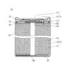
- the structure of a cylindrical lithium ion secondary battery (secondary battery 10) will be described below with reference to FIG. 1.
- the secondary battery 10 includes an electrode group 18, an electrolyte (not shown), and a bottomed cylindrical battery can 22 that accommodates these.
- the sealing body 11 is caulked and fixed to the opening of the battery can 22 with a gasket 21 interposed therebetween. This seals the inside of the battery.
- the sealing body 11 includes a valve body 12, a metal plate 13, and an annular insulating member 14 interposed between the valve body 12 and the metal plate 13.
- the valve body 12 and the metal plate 13 are connected to each other at their respective centers.
- a positive electrode lead 15a led out from the positive electrode 15 is connected to the metal plate 13. Therefore, the valve body 12 functions as a positive external terminal.
- a negative electrode lead 16a led out from the negative electrode 16 is connected to the bottom inner surface of the battery can 22.
- An annular groove 22a is formed near the open end of the battery can 22.
- a first insulating plate 23 is arranged between one end surface of the electrode group 18 and the annular groove 22a.
- a second insulating plate 24 is arranged between the other end surface of the electrode group 18 and the bottom of the battery can 22.
- the electrode group 18 is formed by winding a strip-shaped positive electrode 15 and a strip-shaped negative electrode 16 with a separator 17 in between.
- Second composite particles (average particle diameter 8 ⁇ m, silicon content 55% by mass) and third composite particles (average particle diameter 7 ⁇ m, silicon content 58% by mass) were prepared.
- the second composite particles were mixed with coal pitch, the mixture was fired at 800°C in an inert atmosphere, the surface of the second composite particles was coated with conductive carbon, and the average particle size was controlled by subsequent crushing conditions. .
- the thickness of the conductive layer is estimated to be approximately 100 nm.
- the average grain size of the silicon phase was about 100 nm, and the crystallite size of the silicon phase was 15 nm.
- the third composite material includes an amorphous carbon phase and a silicon phase dispersed within the amorphous carbon phase.
- the average grain size of the silicon phase was about 200 nm, and the crystallite size was 15 nm.
- ⁇ Negative electrode active material> The second composite particles, the third composite particles, and graphite were mixed at a mass ratio of 3:32:65 to prepare a negative electrode active material.
- a negative electrode mixture containing a negative electrode active material, CMC Na salt, and styrene butadiene rubber (SBR) in a mass ratio of 97.5:1:1.5 is dispersed in water as a dispersion medium and mixed.
- a negative electrode slurry was prepared by stirring using a machine.
- the silicon content Cs in the negative electrode mixture (that is, the negative electrode mixture layer to be formed later) is 19.7% by mass, and the content C1 of the first material (the total amount of the first composite particles and the second composite particles) is It was 34.1% by mass.
- the negative electrode slurry was applied to both sides of the copper foil, and the coating film was dried and then rolled to form a negative electrode mixture layer on both sides of the copper foil, thereby obtaining a negative electrode.
- Lithium nickel composite oxide LiNi 0.8 Co 0.18 Al 0.02 O 2
- acetylene black and polyvinylidene fluoride were mixed at a mass ratio of 95:2.5:2.5, and NMP and stirred using a mixer to prepare a positive electrode slurry.
- the positive electrode slurry was applied to both sides of an aluminum foil, and the coated film was dried and then rolled to form a positive electrode mixture layer on both sides of the aluminum foil, thereby obtaining a positive electrode.
- a non-aqueous electrolyte was prepared by dissolving a lithium salt in a non-aqueous solvent.
- a mixed solvent containing ethylene carbonate (EC) and dimethyl carbonate (DMC) at a volume ratio of 30:70 was used as the nonaqueous solvent.
- LiPF 6 was used as the lithium salt. The LiPF 6 concentration was 1.1 mol/L.
- An electrode group was prepared by attaching a tab to each electrode and spirally winding the positive electrode and negative electrode with a separator in between so that the tab was located at the outermost periphery. After inserting the electrode group into an aluminum laminate film exterior body and vacuum drying at 60°C for 12 hours, a non-aqueous electrolyte was injected and the opening of the exterior body was sealed to obtain battery R1 of Reference Example 1. Ta.
- the battery R1 of Reference Example R1 produced above was subjected to predetermined preliminary charging and discharging twice, and then charged in the following manner.
- Battery R1 is charged at an ambient temperature of 25°C with a current of 0.1C until the battery voltage reaches 4.2V, and then with a constant voltage of 4.2V until the current reaches 0.02C. Voltage charged.
- the charging curve at this time is shown in FIG. 2A.
- FIG. 2B at the end of charging, a voltage increase behavior corresponding to the structural change of the positive electrode active material is observed, whereas in FIG. 2A, this is not observed. From this, it can be understood that the battery voltage quickly reached 4.2 V at the end of charging, and the positive electrode potential did not rise as much as expected.
- C(Ah)/X(h) represents the current value when charging or discharging the amount of electricity for the rated capacity over X hours.
- ⁇ Reference example C1 ⁇ [Preparation of negative electrode] A negative electrode slurry was prepared in the same manner as Reference Example R1, except that only graphite was used as the negative electrode active material, and the negative electrode slurry was applied to both sides of a copper foil. After drying, the coating film was rolled to form a copper foil. A negative electrode mixture layer was formed on both sides to obtain a negative electrode.
- the negative electrode was cut into a 20 mm x 20 mm shape with a 5 mm x 5 mm protrusion, and the negative electrode mixture layer on the protrusion was peeled off to expose the copper foil. Thereafter, a negative electrode tab lead was connected to the exposed portion of the negative electrode current collector, and a predetermined area on the outer periphery of the negative electrode tab lead was covered with an insulating film.
- a tab was prepared by welding a small piece of Ni mesh to the end, cut into a predetermined size, and the mesh portion was pressed against a 300 ⁇ m thick lithium metal foil to prepare a counter electrode.
- a negative electrode regulated cell was produced using the above negative electrode and two counter electrodes.
- An electrode group was obtained by sandwiching the negative electrode between a pair of counter electrodes and making the negative electrode mixture layer and lithium metal foil face each other with a separator in between.
- the Al laminate film cut into a rectangle was folded in half, and the two long side ends were heat-sealed to form a cylindrical shape.
- the produced electrode group was placed into a cylinder from one of the short sides, and the end face of the Al laminate film and the insulating film of each tab lead were aligned and heat-sealed.
- a negative electrode slurry was prepared in the same manner as Reference Example R1, except that the second composite particles and graphite were mixed at a mass ratio of 20:80 to prepare a negative electrode active material. After drying the coating film, it was rolled to form a negative electrode mixture layer on both sides of the copper foil to obtain a negative electrode. Then, a test cell E1 was prepared and evaluated in the same manner as Reference Example C1.
- ⁇ Reference example E2 ⁇ A negative electrode slurry was prepared in the same manner as Reference Example R1, except that the third composite particles and graphite were mixed at a mass ratio of 20:80 to prepare a negative electrode active material. After drying the coating film, it was rolled to form a negative electrode mixture layer on both sides of the copper foil to obtain a negative electrode. Then, a test cell E2 was prepared and evaluated in the same manner as Reference Example C1.
- a negative electrode slurry was prepared in the same manner as Reference Example R1, except that the second composite particles, the third composite particles, and graphite were mixed at a mass ratio of 5:25:70 to prepare a negative electrode active material.
- the negative electrode slurry was applied to both sides of the copper foil, and after drying, the coating film was rolled to form a negative electrode mixture layer on both sides of the copper foil, thereby obtaining a negative electrode.
- test cell E3 was produced and evaluated in the same manner as Reference Example C1.
- ⁇ Reference example E4 ⁇ A negative electrode slurry was prepared in the same manner as Reference Example R1, except that the second composite particles and graphite were mixed at a mass ratio of 30:70 to prepare a negative electrode active material. After drying the coating film, it was rolled to form a negative electrode mixture layer on both sides of the copper foil to obtain a negative electrode. Then, test cell E4 was produced and evaluated in the same manner as Reference Example C1.
- ⁇ Reference example E5 ⁇ A negative electrode slurry was prepared in the same manner as Reference Example R1, except that the third composite particles and graphite were mixed at a mass ratio of 30:70 to prepare a negative electrode active material. After drying the coating film, it was rolled to form a negative electrode mixture layer on both sides of the copper foil to obtain a negative electrode. Then, test cell E5 was produced and evaluated in the same manner as Reference Example C1.
- FIG. 3A shows charging curves for cell C1
- FIGS. 3B to 3F show charging curves for E1 to E5.
- 3A to 3E it can be seen that in the cell C1 of Reference Example 2, the polarization of the negative electrode is small, and the negative electrode potential (closed circuit potential) at full charge is higher than the potential of lithium metal.
- the polarization of the negative electrode is large, and the negative electrode potential (closed circuit potential) at the time of full charge is lower than the potential of lithium metal.
- a negative electrode active material was prepared by mixing the second composite particles, the third composite particles, graphite, and the second material (Li 4 Ti 5 O 12 ) at a mass ratio of 3:32:65:3. Except for this, prepare a negative electrode slurry in the same manner as Reference Example R1, apply the negative electrode slurry to both sides of a copper foil, dry the coating film, and then roll it to form a negative electrode mixture layer on both sides of the copper foil, Obtained a negative electrode.
- the silicon content Cs in the negative electrode mixture (that is, the negative electrode mixture layer) is 19.1% by mass, and the content C1 of the first material (the total amount of the first composite particles and the second composite particles) is 33.1 mass%. %, and the content C2 of the second material was 3% by mass. Then, a test cell A1 was prepared and evaluated in the same manner as Reference Example C1.
- a negative electrode active material was prepared by mixing the second composite particles, the third composite particles, graphite, and the second material (Li 4 Ti 5 O 12 ) at a mass ratio of 3:32:65:5. Except for this, prepare a negative electrode slurry in the same manner as Reference Example R1, apply the negative electrode slurry to both sides of a copper foil, dry the coating film, and then roll it to form a negative electrode mixture layer on both sides of the copper foil, Obtained a negative electrode.
- test cell A2 was produced and evaluated in the same manner as Reference Example C1.
- a negative electrode active material was prepared by mixing the second composite particles, the third composite particles, graphite, and the second material (Li 4 Ti 5 O 12 ) at a mass ratio of 3:32:65:10. Except for this, prepare a negative electrode slurry in the same manner as Reference Example R1, apply the negative electrode slurry to both sides of a copper foil, dry the coating film, and then roll it to form a negative electrode mixture layer on both sides of the copper foil, Obtained a negative electrode.
- test cell A3 was produced and evaluated in the same manner as Reference Example C1.
- a negative electrode active material was prepared by mixing the second composite particles, the third composite particles, graphite, and the second material (Li 4 Ti 5 O 12 ) at a mass ratio of 3:32:65:15. Except for this, prepare a negative electrode slurry in the same manner as Reference Example R1, apply the negative electrode slurry to both sides of a copper foil, dry the coating film, and then roll it to form a negative electrode mixture layer on both sides of the copper foil, Obtained a negative electrode.
- test cell A4 was produced and evaluated in the same manner as Reference Example C1.
- a negative electrode active material was prepared by mixing the second composite particles, the third composite particles, and graphite at a mass ratio of 3:32:65 without using the second material (Li 4 Ti 5 O 12 ).
- a negative electrode slurry was prepared in the same manner as Reference Example R1, the negative electrode slurry was applied to both sides of a copper foil, and after drying the coating film, it was rolled to form a negative electrode mixture layer on both sides of the copper foil. , a negative electrode was obtained.
- test cell A5 was produced and evaluated in the same manner as Reference Example C1.
- FIG. 4 shows the charging curves of cells A1 to A5.
- the solid line curve is the curve of cell A5 not using the second material, and the higher the SOC at the end of charging, the higher the content of the second material. That is, the curves belong to cells A1 to A4 in order from the left side to the right side.
- FIG. 5 shows an enlarged view of FIG. 4 at the end of charging.
- Figure 6 also shows the SOC (negative potential rush SOC (%)) of the test cell when the closed circuit potential of the negative electrode reaches the potential of lithium metal and the content rate of the second material in the negative electrode mixture layer (additional (%)).
- the SOC of the test cell when the closed circuit potential of the negative electrode reaches the potential of lithium metal changes depending on the content C2 of the second material in the negative electrode mixture layer. Furthermore, it can be understood that the larger the content C2, the greater the effect of increasing the negative electrode potential at the end of charging during charging.
- a non-aqueous electrolyte secondary battery including a negative electrode for a non-aqueous electrolyte secondary battery according to the present disclosure is suitable for main power sources for mobile communication devices, portable electronic devices, etc., automotive power sources, etc.; It is not limited.
Abstract
非水電解質二次電池用負極であって、負極は、負極活物質を含む負極合剤層を有し、負極活物質は、シリコンを含む第1材料と、シリコンよりも高いLiとの反応電位を有する第2材料と、を含み、負極合剤層中のシリコンの含有率Csが、10質量%以上である、非水電解質二次電池用負極。
Description
本発明は、主として非水電解質二次電池用負極に関する。
非水電解質二次電池、特にリチウムイオン二次電池は、高電圧かつ高エネルギー密度を有するため、小型民生用途、電力貯蔵装置および電気自動車の電源として期待されている。電池の高エネルギー密度化が求められる中、理論容量密度の高い負極活物質として、リチウムと合金化するシリコン含有材料の利用が期待されている。
例えば、特許文献1は、珪素原子を含む材料から成る基材粒子を準備し、基材粒子の表面に炭素被膜を形成して被覆粒子とするリチウムイオン二次電池用負極材の製造方法において、基材粒子として、珪素粒子、珪素の微粒子が珪素系化合物に分散した複合構造を有する粒子、一般式SiOx(0.5≦x≦1.6)で表される酸化珪素粒子、又はこれらの混合物を用いることを提案している。
非水電解質二次電池を高容量化するには、負極中のシリコンの含有率を高めることが有効である。しかし、シリコンの含有率を高めると、負極の分極が大きくなり、充電時における負極電位(閉回路電位)がリチウム金属の電位よりも低くなることがある。その場合、想定よりも早期に充電終止電圧に到達してしまい、正極の電位が十分に上がらず、容量の利用率が低下する。
本発明の一側面は、非水電解質二次電池用負極に関する。前記負極は、負極活物質を含む負極合剤層を有し、前記負極活物質は、シリコンを含む第1材料と、シリコンよりも高いLiとの反応電位を有する第2材料と、を含み、前記負極合剤層中の前記シリコンの含有率Csが、10質量%以上である、非水電解質二次電池用負極に関する。
本発明の別の側面は、正極と、上記の負極と、前記正極と前記負極との間に配置されたセパレータと、非水電解質と、を備える、非水電解質二次電池に関する。
本開示によれば、負極の閉回路電位の低下が抑制されるため、想定よりも早期に充電終止電圧に到達する現象を起こりにくくすることができる。
本発明の新規な特徴を添付の請求の範囲に記述するが、本発明は、構成および内容の両方に関し、本発明の他の目的および特徴と併せ、図面を照合した以下の詳細な説明によりさらによく理解されるであろう。
以下、本開示の実施形態について例を挙げて説明するが、本開示は以下で説明する例に限定されない。以下の説明では、具体的な数値、材料等を例示する場合があるが、本開示の効果が得られる限り、他の数値、材料等を適用してもよい。なお、本開示に特徴的な部分以外の構成要素には、公知の非水電解質二次電池およびその負極の構成要素を適用してもよい。この明細書において、「数値A~数値Bの範囲」という場合、当該範囲には数値Aおよび数値Bが含まれる。複数の材料が例示される場合、その中から1種を選択して単独で用いてもよく、2種以上を組み合わせて用いてもよい。また、本開示は、添付の特許請求の範囲に記載の複数の請求項から任意に選択される2つ以上の請求項に記載の事項の組み合わせを包含する。つまり、技術的な矛盾が生じない限り、添付の特許請求の範囲に記載の複数の請求項から任意に選択される2つ以上の請求項に記載の事項を組み合わせることができる。
以下、非水電解質二次電池の一例として、主に、リチウムイオン二次電池について説明するが、本発明に係る非水電解質二次電池は、発明の趣旨と矛盾しない限り、液体、ゲルもしくは固体の非水電解質を具備する二次電池を広く包含する。例えば、本発明は、全固体二次電池などにも適用し得る。
非水電解質二次電池は、一般に、電極群と、非水電解質と、電極群と非水電解質とを収容する電池ケースとを具備する。電極群は、正極と、負極と、正極と負極との間に配置されるセパレータとを備える。
本実施形態に係る負極は、負極活物質を含む負極合剤層を有する。負極合剤層は、例えば、シート状の負極集電体の表面に設けられる。負極合剤層は、負極活物質を主成分として含む負極合剤で構成されるため、負極活物質層と言い換えてもよい。負極合剤は、負極活物質を主成分とする混合物であり、任意成分として結着剤、導電剤などを含み得る。
負極活物質は、少なくとも、第1材料と第2材料とを含む。第1材料および第2材料は、いずれもファラデー反応により容量を発現する活性材料である。すなわち、第1材料および第2材料は、電池反応に伴ってリチウムイオンの吸蔵と放出(もしくは挿入と脱離)を行う活性材料である。ただし、第1材料の全体が活性材料である必要はなく、第1材料の少なくとも一部が活性材料で構成されていればよい。また、第2材料の全体が活性材料である必要はなく、第2材料の少なくとも一部が活性材料で構成されていればよい。ここでは、第1材料は、Liと反応して合金化するシリコンを含めばよい。シリコンの表面は酸化されていてもよく、例えば、自然酸化皮膜を有してもよい。第2材料は、シリコンよりも高いLiとの反応電位を有する活性材料を含めばよい。
第1材料と第2材料とを対比すると、第2材料のLiとの反応電位は、第1材料よりも高くなる。第1材料と第2材料とを負極合剤層内に混在させることにより、負極電位は、少なくとも第1材料の電位と第2材料の電位の影響を受けた混成電位になる。そのような混成電位は、第1材料の電位よりも高くなる。その結果、負極合剤層中の第1材料の含有率(換言すれば、シリコンの含有率)が相当に高められた場合でも、充電中に負極電位がリチウム金属の電位に到達しにくくなる。よって、電池電圧が充電終止電圧に到達するときの正極電位を十分に上昇させることができるようになり、容量の利用率が向上する。
負極電位が早期に過度に低くなり、想定よりも早期に充電終止電圧に到達する現象は、負極合剤層中の第1材料の含有率が相当に高められた場合に顕在化する。具体的には、負極合剤層中のシリコンの含有率Csが10質量%以上であるときに、そのような現象が顕在化する。従来、実用化された電池では、負極合剤層中のシリコンの含有率Csが小さかったため、そのような現象は顕在化しなかった。
一方、非水電解質二次電池の更なる高容量化を達成するには、負極合剤層中のシリコンの含有率Csを10質量%以上とすることが有効であり、12質量%以上、更には20質量%以上とすることが望まれる。その場合、第2材料を用いて負極の平均的な電位をベースアップすることが、電池電圧が充電終止電圧に到達するときの正極電位を上昇させる上で有効であることが判明した。
なお、充電終止電圧とは、満充電状態の電池の電圧(閉回路電圧)に対応する。一方、放電終止電圧は、完全放電状態の電池の電圧(閉回路電圧)に対応する。放電深度(DOD)100%の完全放電状態の電池を、充電状態(SOC:充電深度)100%の満充電状態(DOD=0%)になるまで充電するときの充電電気量が定格容量に相当する。非水電解質二次電池の充放電は、所定の制御回路に制御される。そのような制御回路は、予め設定された充電終止電圧(例えば4.2V)に達すると、充電を停止するように制御される。負極の分極が大きくなるほど、電池電圧が上昇しやすくなるため、十分な電気量を蓄電する前に早期に充電終止電圧に達しやすくなる。本開示によれば、そのような現象を抑制することができる。
第2材料は、充放電に寄与するシリコンを含まない材料であり、シリコン(もしくは、シリコン相)を含む第1材料のようには、負極の高容量化に寄与しない。従って、第2材料は、第1材料による高容量化の効果が損なわれない量で用いることが望ましい。高容量化の効果を高める観点からは、負極合剤層中の第1材料の含有率C1が、負極合剤層中の第2材料の含有率C2よりも、大きいことが望ましい。具体的には、含有率C2は、含有率C1の0.5倍以下(C2/C1≦0.5)でもよい。
負極合剤層中のシリコンの含有率Csを、含有率C2よりも大きくしてもよい。具体的には、含有率Csは、含有率C2の1.5倍以上(Cs/C2≧1.5)でもよく、2倍以上(Cs/C2≧2)でもよい。シリコン相の含有率Csが大きいほど、高容量化に有利である。一方、負極の分極を抑制するとともにシリコン相の膨張と収縮による負極の劣化を抑制する観点から、シリコンの含有率Csを30質量%以下に制限してもよい。
負極合剤層中の第2材料の含有率C2は、特に限定されず、僅かでも負極合剤層中に第2材料が含まれていれば、それに応じて混成電位が形成され、充電時の負極電池の低下を抑制する効果が得られる。一方、含有率C2が大きいほど、充電時の負極電位の低下を抑制する効果は大きくなる。より有意な効果を得る観点からは、含有率C2が、0.5質量%以上が望ましく、3質量%以上でもよく、5質量%以上もしくは10質量%以上でもよい。一方、第2材料は、第1材料ほどに高容量化に寄与しないため、含有率C2は、例えば15質量%以下でもよく、10質量%以下でもよい。
第1材料は、シリコンを含めばよく、実質的にシリコン(もしくは、シリコン相)のみから構成されていてもよく、シリコン以外の材料を含む複合粒子でもよい。第1材料は、1種を単独で用いてもよく、2種以上を組み合わせて用いてもよい。
第1材料は、シリコン相と、シリコン相が分散するマトリックス相とを含む複合粒子であってもよい。マトリックス相は、リチウムイオン伝導性を有する材料で構成されていればよい。マトリックス相は、例えば、酸化ケイ素相および炭素相からなる群より選択される少なくとも1種を含む。
酸化ケイ素相は、SiとOとを含み、更に、SiおよびO以外の第3元素を含んでもよい。酸化ケイ素相は、SiO2で構成されてもよく、リチウムシリケートで構成されてもよく、これらの両者で構成されてもよい。
第1材料である複合粒子(シリコン相と、シリコン相が分散するマトリックス相とを含む複合粒子)は、例えば、以下(a)~(c)のいずれかの形態であってもよい。
(a)シリコン相と、シリコン相が分散する二酸化ケイ素(SiO2)相と、を含む第1複合粒子。
(b)シリコン相と、シリコン相が分散するリチウムシリケート相と、を含む第2複合粒子。
(c)シリコン相と、シリコン相が分散する炭素相と、を含む第3複合粒子。
第1、第2および第3複合粒子は、いずれも、マトリックス相に分散するシリコン相を含むとともに、マトリックス相に分散する第2材料を含んでもよい。すなわち、第1材料と第2材料とが複合化していずれかの複合粒子を形成してもよい。この場合、第1材料はシリコン相のみで構成されると把握でき、第1材料の全体が活性材料(シリコン相)と見なしてよい。
負極合剤層は、例えば、以下(A)~(C)のいずれかの形態であってもよい。
(A)第1材料の粒子と、第2材料の粒子と、の混合物を含む、負極合剤層。
(B)第1材料および第2材料が粒子状に複合化された複合粒子(例えば、既述の第1、第2および第3複合粒子)を含む、負極合剤層。
(C)第1材料と第2材料とが粒子状に複合化された複合粒子(例えば、既述の第1、第2および第3複合粒子)と、そのような複合粒子以外の第3材料の粒子(例えば、黒鉛、難黒鉛化炭素、易黒鉛化炭素等の炭素質粒子)と、の混合物を含む、負極合剤層。
第1複合粒子(二酸化ケイ素(SiO2)相と、二酸化ケイ素(SiO2)相に分散するシリコン相と、を含む)は、第1材料の中でも安定性が高く、体積変化も小さい点で優れている。高い安定性は、二酸化ケイ素相に分散するシリコン相(もしくはシリコン粒子)の粒子径が小さく、深い充電が進行しにくいためと考えられる。二酸化ケイ素相は、リチウムイオンを不可逆的にトラップするサイトが比較的多いため、第1材料の中では不可逆容量が大きくなる傾向があるが、その分、構造安定性が高く、体積変化が抑制されやすい。
第1複合粒子は、例えば、非酸化性雰囲気中で、原料ケイ素酸化物を加熱し、不均化反応を行うことで合成できる。不均化反応では、シリコン微粒子が、二酸化ケイ素相中に均一に生成し得る。不均化反応により生成するシリコン微粒子の平均粒径は、例えば、100nm未満であり、5nm~50nmであり得る。第1複合粒子のマトリックス相は、例えば95~100質量%が二酸化ケイ素で構成され得る。第1複合粒子の全体の組成は、一般式SiOx(0<x<2)で表すことができる。
第1複合粒子に含まれるシリコン相の含有率は、例えば、20質量%~60質量%であり得る。
第2複合粒子(リチウムシリケート相と、リチウムシリケート相に分散するシリコン相と、を含む)は、第1材料の中でも不可逆容量が小さい点で優れている。第2複合粒子を用いる場合、優れた充放電効率が得られる。特に充放電の初期に、その効果が顕著である。
リチウムシリケート相は、Li、SiおよびO以外に、第3元素として、長周期型周期表の第1族元素(Li以外)および第2族元素からなる群より選択される少なくとも1種を含んでもよい。第1族元素および第2族元素は、例えば、K、Na、Mg、Ca、Sr、Baなどであり得る。リチウムシリケート相は、更に、Al、B、La、P、Zr、Ti、Fe、Cr、Ni、Mn、Cu、Mo、Znなどを含んでもよい。
リチウムシリケート相におけるSi原子数に対するO原子数の比(O/Si)は、例えば、2より大きく、4未満である。この場合、安定性およびリチウムイオン伝導性の面で有利である。O/Si比は、2より大きく、3未満でもよい。リチウムシリケート相におけるSi原子数に対するLi原子数の比(Li/Si)は、例えば、0より大きく、4未満である。
リチウムシリケートの組成は、一般式Li2zSiO2+z(0<z<2)で表すことができる。リチウムシリケートの安定性、作製容易性およびリチウムイオン伝導性の観点から、zは、0<z<1を満たすことが好ましく、z=1/2がより好ましい。
第2複合粒子は、例えば、リチウムシリケートと原料シリコンとを混合し、ボールミル等の攪拌機で混合物を破砕しながら攪拌し、その後、混合物を不活性雰囲気中で焼成すれば得ることができる。混合物を焼結し、焼結体を粉砕して。第2複合粒子としてもよい。
第2複合粒子に含まれるシリコン相の含有率は、例えば、35質量%以上、80質量%以下であり得る。第2複合粒子は、シリコン相の含有率を任意に変化させ得るため、高容量負極の設計が容易である。
第3複合粒子(炭素相と、炭素相に分散するシリコン相と、を含む)は、第1材料の中でも不可逆容量が小さい点で優れている。また、炭素相は、リチウムイオンとのファラデー反応により容量を発現し得るため、第1材料の中でも、高容量化に有利である。
炭素相は、結晶性炭素(黒鉛)を含んでもよく、結晶性の低い無定形炭素(すなわちアモルファス炭素)を含んでもよい。無定形炭素は、例えば、難黒鉛化炭素でもよく、易黒鉛化炭素でもよく、それ以外でもよい。
第3複合粒子は、例えば、炭素源と原料シリコンとを混合し、ボールミル等の攪拌機で混合物を破砕しながら攪拌し、その後、混合物を不活性雰囲気中で焼成すれば得ることができる。混合物を焼結し、焼結体を粉砕して。第3複合粒子としてもよい。
炭素源としては、例えば、糖類、水溶性樹脂等を用い得る。例えば、炭素源として、カルボキシメチルセルロース(CMC)、ポリビニルピロリドン、セルロース、スクロースなどを用いてもよい。炭素源と原料シリコンとを混合する際、炭素源と原料シリコンを、アルコールなどの液状有機物の分散媒中に分散させてもよい。
第3複合粒子に含まれるシリコン相の含有率は、例えば、40質量%以上、80質量%以下であり得る。第3複合粒子は、シリコン相の含有率を任意に変化させ得るため、高容量負極の設計が容易である。
第2複合粒子または第3複合粒子中のシリコン相(もしくはシリコン粒子)の平均粒径は、例えば、100nm以上、500nm以下であり、400nm以下であってもよく、200nm以下であってもよい。シリコン相が、このように大きな平均粒径を有することで、これら複合粒子の容量を高めやすくなる。
第2複合粒子または第3複合粒子のマトリックス相内に分散しているシリコン相は、複数の結晶子で構成され得る。結晶子サイズは、例えば、30nm以下でもよく、25nm以下でもよい。この場合、充放電に伴うシリコン相の膨張と収縮による体積変化を極力小さくできる。結晶子サイズは、特に限定されないが、例えば、5μm以上でもよく、10nm以上でもよい。シリコン相の結晶子サイズは、シリコン相のX線回折(XRD)パターンのSi(111)面に帰属される回析ピークの半値幅からシェラーの式により算出される。
第1、第2および第3複合材料の平均粒径は、例えば、2μm~10μmでもよく、4μm~7μmでもよい。これにより、充放電に伴うシリコン相の体積変化による応力を緩和しやすくなる。平均粒径は、例えばレーザー回折散乱法で測定される粒度分布において、体積積算値が50%となる粒径(体積平均粒径)を意味する。測定装置には、例えば、株式会社堀場製作所(HORIBA)製「LA-750」を用いることができる。
第1、第2および第3複合材料中のシリコン相の含有率は、例えば、Si-NMRにより測定することができる。
第1、第2および第3複合材料中のシリコン相の平均粒径は、複合粒子の断面SEM(走査型電子顕微鏡)写真から測定し得る。具体的には、シリコン相の平均粒径は、任意の100個のシリコン粒子の最大径を平均して求められる。
第2材料は、シリコンよりもLiとの反応電位が高い活性材料を含めばよい。ただし、充電中の負極の混成電位を効果的に上昇させる観点から、第2材料のLiとの反応電位は、リチウム金属の電位よりも0.5V以上高いことが望ましい。そのような第2材料は、通常は、炭素質材料以外であり、例えば、金属化合物が有望である。第2材料は、1種を単独で用いてもよく、2種以上を組み合わせて用いてもよい。
第2材料として用い得る金属化合物は、例えば、スピネル構造、ペロブスカイト構造、層状岩塩型構造などの結晶構造を有してもよい。具体的には、スピネル型構造を有するリチウムチタン複合酸化物やリチウムマンガン複合酸化物、リチウムイオン二次電池の正極活物質として公知の層状岩塩型構造のリチウム含有遷移金属酸化物などを用いてもよい。中でも、リチウムチタン複合酸化物は、Liとの反応電位がリチウム金属の電位に対して1.5V~1.6V程度であり、非水電解質二次電池の負極活物質として優れた性能を発現する点で好ましい。
スピネル型結晶構造を有するリチウムチタン複合酸化物は、例えば一般式Li4+zTi5O12(0≦z≦1)で表される。リチウムチタン複合酸化物は、リチウムイオンの受け入れ性が高く、負極におけるイオンの拡散抵抗を低減しやすい点でも優れている。最も典型的な材料は、Li4Ti5O12である。
一般式:LivTi5-wMwO12+t(3≦v≦5、0.005≦w≦1.5、-1≦t≦1)で表されるリチウムチタン複合酸化物を用いてもよい。Mは、例えばV、Mn、Fe、Co、Ni、Cu、Zn、Al、B、Mg、Ca、Sr、Ba、Zr、Nb、Mo、W、Bi、Na、Kおよび希土類元素よりなる群から選択された少なくとも1種である。
リチウムチタン複合酸化物の平均粒径は、負極合剤層内での分散性を確保し、均一な混成電位を形成する観点から、例えば、20μm以下であり、10μm以下でもよい。リチウムチタン複合酸化物の平均粒径は、例えば0.4μm以上でもよく、0.6μm以上でもよい。ここでも、平均粒径は、例えばレーザー回折散乱法で測定される粒度分布における体積積算値50%の体積平均粒径を意味する。
負極活物質は、第1材料と第2材料に加え、更に、炭素質粒子を含み得る。炭素質粒子は、第1材料に比べ、充放電時の膨張および収縮の度合いが小さいため、サイクル特性を向上させやすい。また、炭素質粒子は、第2材料に比べてLiとの反応電位が低く、高容量化に有利である。
負極活物質中の炭素質粒子(第1材料のマトリックス相としての炭素相を除く。)の含有率は、例えば、70質量%~90質量%であればよい。これにより、高容量化とサイクル特性とを両立しやすくなる。
炭素質粒子としては、例えば、黒鉛、易黒鉛化炭素(ソフトカーボン)、難黒鉛化炭素(ハードカーボン)等が例示できる。中でも、充放電の安定性に優れ、不可逆容量が少ない黒鉛が好ましい。黒鉛とは、黒鉛型結晶構造を有する材料を意味し、例えば、天然黒鉛、人造黒鉛、黒鉛化メソフェーズカーボン粒子等が含まれる。炭素材料は、1種を単独で用いてもよく、2種以上を組み合わせて用いてもよい。
次に、本開示の実施形態に係る非水電解質二次電池の一例であるリチウムイオン二次電池について概説する。リチウムイオン二次電池は、例えば、以下のような負極と、正極と、非水電解質とを備える。
[負極]
負極は、負極集電体と、負極合剤層とを具備する。負極合剤層は、例えば、負極活物質を含む負極合剤を分散媒に分散させた負極スラリーを負極集電体の表面に塗布し、乾燥後の塗膜を圧延することで形成される。負極合剤層は、負極集電体の一方の表面に形成してもよく、両方の表面に形成してもよい。
負極は、負極集電体と、負極合剤層とを具備する。負極合剤層は、例えば、負極活物質を含む負極合剤を分散媒に分散させた負極スラリーを負極集電体の表面に塗布し、乾燥後の塗膜を圧延することで形成される。負極合剤層は、負極集電体の一方の表面に形成してもよく、両方の表面に形成してもよい。
負極合剤は、必須成分として、負極活物質を含み、任意成分として、結着剤、導電剤、増粘剤などを含む。
負極集電体は、シート状であり、金属箔、メッシュ体、ネット、パンチングシートなどが使用される。負極集電体の材質として、ステンレス鋼、ニッケル、ニッケル合金、銅、銅合金などが例示できる。負極集電体の厚さは、特に限定されないが、例えば、1μm~50μmであり、5μm~20μmでもよい。
結着剤としては、樹脂材料が用いられる。例えば、フッ素樹脂、ポリオレフィン樹脂、ポリアミド樹脂、ポリイミド樹脂、アクリル樹脂、ビニル樹脂、ゴム状材料などが例示できる。
導電剤としては、例えば、カーボンブラック、カーボンナノチューブ等が例示できる。
増粘剤としては、例えば、カルボキシメチルセルロース(CMC)、CMCの変性体(Na塩等)、セルロース誘導体、ポリビニルアルコール、ポリエーテルなどが挙げられる。
分散媒としては、例えば、水、アルコール、エーテル、N-メチル-2-ピロリドン(NMP)などが例示できる。
[正極]
正極は、電気化学的にリチウムイオンを吸蔵および放出可能な正極活物質を含む。正極は、例えば、正極集電体と、正極合剤層とを具備する。正極合剤層は、例えば、正極活物質を含む正極合剤を分散媒に分散させた正極スラリーを正極集電体の表面に塗布し、乾燥後の塗膜を圧延することで形成される。正極合剤層は、正極集電体の一方の表面に形成してもよく、両方の表面に形成してもよい。
正極は、電気化学的にリチウムイオンを吸蔵および放出可能な正極活物質を含む。正極は、例えば、正極集電体と、正極合剤層とを具備する。正極合剤層は、例えば、正極活物質を含む正極合剤を分散媒に分散させた正極スラリーを正極集電体の表面に塗布し、乾燥後の塗膜を圧延することで形成される。正極合剤層は、正極集電体の一方の表面に形成してもよく、両方の表面に形成してもよい。
正極合剤は、必須成分として、正極活物質を含み、任意成分として、結着剤、導電剤などを含む。
正極活物質としては、例えば、リチウム含有遷移金属酸化物を用いることができる。例えば、LiaCoO2、LiaNiO2、LiaMnO2、LiaCobNi1-bO2、LiaCobM1-bOc、LiaNi1-bMbOc、LiaMn2O4、LiaMn2-bMbO4、LiMPO4、Li2MPO4F(Mは、Na、Mg、Sc、Y、Mn、Fe、Co、Ni、Cu、Zn、Al、Cr、Pb、Sb、Bよりなる群から選択される少なくとも1種である。)が挙げられる。ここで、a=0~1.2、b=0~0.9、c=2.0~2.3である。なお、リチウムのモル比を示すa値は、充放電により増減する。
中でも、LiaNibM1-bO2(Mは、Mn、CoおよびAlよりなる群から選択された少なくとも1種であり、0<a≦1.2であり、0.3≦b≦1である。)で表されるリチウムニッケル複合酸化物が好ましい。高容量化の観点から、0.80≦b≦1を満たすことがより好ましい。結晶構造の安定性の観点からは、MとしてCoおよびAlを含むLiaNibCocAldO2(0<a≦1.2、0.80≦b<1、0<c<0.20、0<d≦0.1、b+c+d=1)が更に好ましい。
結着剤および導電剤としては、例えば、負極について例示した材料を任意に使用できる。導電剤として、天然黒鉛、人造黒鉛等の黒鉛を用いてもよい。
正極集電体は、シート状であり、金属箔、メッシュ体、ネット、パンチングシートなどが使用される。正極集電体の材質として、例えば、ステンレス鋼、アルミニウム、アルミニウム合金、チタンなどが例示できる。正極集電体の厚さは、特に限定されないが、例えば、1μm~50μmであり、5μm~20μmでもよい。
[非水電解質]
非水電解質は、液状電解質(電解液)でもよく、ゲル状電解質でもよく、固体電解質でもよい。ゲル状電解質は、リチウム塩とマトリックスポリマーを含み、あるいは、リチウム塩と非水溶媒とマトリックスポリマーとを含む。マトリックスポリマーとしては、例えば、非水溶媒を吸収してゲル化するポリマー材料が使用される。ポリマー材料としては、フッ素樹脂、アクリル樹脂、ポリエーテル樹脂、ポリエチレンオキシド等が挙げられる。固体電解質は、無機固体電解質でもよい。無機固体電解質としては、例えば、全固体リチウムイオン二次電池等で公知の材料(例えば、酸化物系固体電解質、硫化物系固体電解質、ハロゲン化物系固体電解質等)が使用される。
非水電解質は、液状電解質(電解液)でもよく、ゲル状電解質でもよく、固体電解質でもよい。ゲル状電解質は、リチウム塩とマトリックスポリマーを含み、あるいは、リチウム塩と非水溶媒とマトリックスポリマーとを含む。マトリックスポリマーとしては、例えば、非水溶媒を吸収してゲル化するポリマー材料が使用される。ポリマー材料としては、フッ素樹脂、アクリル樹脂、ポリエーテル樹脂、ポリエチレンオキシド等が挙げられる。固体電解質は、無機固体電解質でもよい。無機固体電解質としては、例えば、全固体リチウムイオン二次電池等で公知の材料(例えば、酸化物系固体電解質、硫化物系固体電解質、ハロゲン化物系固体電解質等)が使用される。
液状電解質(電解液)は、例えば、非水溶媒と電解質塩とを含む。電解質塩は、少なくともリチウム塩を含む。非水電解質におけるリチウム塩濃度は、例えば0.5mol/L以上、2mol/L以下が好ましい。
非水溶媒として、例えば、環状炭酸エステル、鎖状炭酸エステル、環状カルボン酸エステル、鎖状カルボン酸エステルなどが用いられる。
リチウム塩としては、例えば、LiClO4、LiBF4、LiPF6、LiAlCl4、LiSbF6、LiSCN、LiCF3SO3、LiCF3CO2、LiAsF6、イミド塩類などが挙げられる。イミド塩としては、ビスフルオロスルホニルイミドリチウム(LiN(FSO2)2)、ビストリフルオロメタンスルホン酸イミドリチウム(LiN(CF3SO2)2)などが挙げられる。
[セパレータ]
正極と負極との間にセパレータを介在させてもよい。セパレータは、イオン透過度が高く、適度な機械的強度および絶縁性を備えている。セパレータとして、微多孔膜、織布、不織布などを用いることができる。セパレータの材質は、例えば、ポリプロピレン、ポリエチレンなどのポリオレフィンを含む。
正極と負極との間にセパレータを介在させてもよい。セパレータは、イオン透過度が高く、適度な機械的強度および絶縁性を備えている。セパレータとして、微多孔膜、織布、不織布などを用いることができる。セパレータの材質は、例えば、ポリプロピレン、ポリエチレンなどのポリオレフィンを含む。
[リチウムイオン二次電池]
リチウムイオン二次電池は、どのような形態でもよく、例えば、円筒形、角形、コイン形、ボタン形、ラミネート形などの形態を有する。以下、円筒形のリチウムイオン二次電池(二次電池10)の構造を、図1を参照しながら説明する。
リチウムイオン二次電池は、どのような形態でもよく、例えば、円筒形、角形、コイン形、ボタン形、ラミネート形などの形態を有する。以下、円筒形のリチウムイオン二次電池(二次電池10)の構造を、図1を参照しながら説明する。
二次電池10は、電極群18と、電解質(図示せず)と、これらを収容する有底円筒形の電池缶22とを具備する。電池缶22の開口部にガスケット21を介して封口体11がかしめ固定されている。これにより電池内部が密閉されている。封口体11は、弁体12と、金属板13と、弁体12と金属板13との間に介在する環状の絶縁部材14と、を具備する。弁体12と金属板13は、それぞれの中心部において、互いに接続されている。正極15から導出された正極リード15aは、金属板13に接続されている。よって、弁体12は、正極の外部端子として機能する。負極16から導出された負極リード16aは、電池缶22の底部内面に接続されている。電池缶22の開口端の近傍には環状溝部22aが形成されている。電極群18の一方の端面と環状溝部22aとの間には、第1絶縁板23が配置されている。電極群18の他方の端面と電池缶22の底部との間には、第2絶縁板24が配置されている。電極群18は、帯状の正極15と帯状の負極16とをセパレータ17を介して捲回して形成されている。
以下、本開示を実施例および比較例に基づいて具体的に説明するが、本開示は以下の実施例に限定されるものではない。
《参考例R1》
第1材料として、第2複合粒子(平均粒径8μm、シリコン含有率55質量%)と、第3複合粒子(平均粒径7μm、シリコン含有率58質量%)とを準備した。
第1材料として、第2複合粒子(平均粒径8μm、シリコン含有率55質量%)と、第3複合粒子(平均粒径7μm、シリコン含有率58質量%)とを準備した。
(第2複合粒子)
第2複合粒子は、Li2Si2O5(z=0.5)で表わされるリチウムシリケート相と、リチウムシリケート相内に分散しているシリコン相と、を含む。第2複合粒子は、石炭ピッチと混合し、混合物を不活性雰囲気で、800℃で焼成し、第2複合粒子の表面を導電性炭素で被覆し、その後の粉砕条件により平均粒径を制御した。導電層の厚さは、概ね100nmと推測される。シリコン相の平均粒径は約100nm、シリコン相の結晶子サイズは15nmであった。
第2複合粒子は、Li2Si2O5(z=0.5)で表わされるリチウムシリケート相と、リチウムシリケート相内に分散しているシリコン相と、を含む。第2複合粒子は、石炭ピッチと混合し、混合物を不活性雰囲気で、800℃で焼成し、第2複合粒子の表面を導電性炭素で被覆し、その後の粉砕条件により平均粒径を制御した。導電層の厚さは、概ね100nmと推測される。シリコン相の平均粒径は約100nm、シリコン相の結晶子サイズは15nmであった。
(第3複合粒子)
第3複合材料は、無定形炭素相と、無定形炭素相内に分散しているシリコン相と、を含む。シリコン相の平均粒径は約200nm、結晶子サイズは15nmであった。
第3複合材料は、無定形炭素相と、無定形炭素相内に分散しているシリコン相と、を含む。シリコン相の平均粒径は約200nm、結晶子サイズは15nmであった。
<負極活物質>
第2複合粒子と、第3複合粒子と、黒鉛とを、3:32:65の質量比で混合し、負極活物質を調製した。
第2複合粒子と、第3複合粒子と、黒鉛とを、3:32:65の質量比で混合し、負極活物質を調製した。
[負極の作製]
負極活物質と、CMCのNa塩と、スチレンブタジエンゴム(SBR)とを、97.5:1:1.5の質量比で含む負極合剤を、分散媒である水に分散させて、混合機を用いて攪拌し、負極スラリーを調製した。負極合剤(すなわち、後に形成される負極合剤層)中のシリコン含有率Csは19.7質量%、第1材料(第1複合粒子と第2複合粒子の合計量)の含有率C1は34.1質量%であった。負極スラリーを、銅箔の両面に塗布し、塗膜を乾燥後、圧延して、銅箔の両面に負極合剤層を形成し、負極を得た。
負極活物質と、CMCのNa塩と、スチレンブタジエンゴム(SBR)とを、97.5:1:1.5の質量比で含む負極合剤を、分散媒である水に分散させて、混合機を用いて攪拌し、負極スラリーを調製した。負極合剤(すなわち、後に形成される負極合剤層)中のシリコン含有率Csは19.7質量%、第1材料(第1複合粒子と第2複合粒子の合計量)の含有率C1は34.1質量%であった。負極スラリーを、銅箔の両面に塗布し、塗膜を乾燥後、圧延して、銅箔の両面に負極合剤層を形成し、負極を得た。
[正極の作製]
リチウムニッケル複合酸化物(LiNi0.8Co0.18Al0.02O2)と、アセチレンブラックと、ポリフッ化ビニリデンとを、95:2.5:2.5の質量比で混合し、NMPに分散させて、混合機を用いて攪拌し、正極スラリーを調製した。正極スラリーを、アルミニウム箔の両面に塗布し、塗膜を乾燥後、圧延して、アルミニウム箔の両面に正極合剤層を形成し、正極を得た。
リチウムニッケル複合酸化物(LiNi0.8Co0.18Al0.02O2)と、アセチレンブラックと、ポリフッ化ビニリデンとを、95:2.5:2.5の質量比で混合し、NMPに分散させて、混合機を用いて攪拌し、正極スラリーを調製した。正極スラリーを、アルミニウム箔の両面に塗布し、塗膜を乾燥後、圧延して、アルミニウム箔の両面に正極合剤層を形成し、正極を得た。
[非水電解質の調製]
非水溶媒にリチウム塩を溶解させて非水電解質を調製した。非水溶媒には、エチレンカーボネート(EC)と、ジメチルカーボネート(DMC)とを、30:70の体積比で含む混合溶媒を用いた。リチウム塩には、LiPF6を用いた。LiPF6濃度は1.1mol/Lとした。
非水溶媒にリチウム塩を溶解させて非水電解質を調製した。非水溶媒には、エチレンカーボネート(EC)と、ジメチルカーボネート(DMC)とを、30:70の体積比で含む混合溶媒を用いた。リチウム塩には、LiPF6を用いた。LiPF6濃度は1.1mol/Lとした。
[リチウムイオン二次電池の作製]
各電極にタブをそれぞれ取り付け、タブが最外周部に位置するように、セパレータを介して正極および負極を渦巻き状に巻回することにより電極群を作製した。電極群をアルミニウムラミネートフィルム製の外装体内に挿入し、60℃で12時間真空乾燥した後、非水解質を注入し、外装体の開口部を封止して、参考例1の電池R1を得た。
各電極にタブをそれぞれ取り付け、タブが最外周部に位置するように、セパレータを介して正極および負極を渦巻き状に巻回することにより電極群を作製した。電極群をアルミニウムラミネートフィルム製の外装体内に挿入し、60℃で12時間真空乾燥した後、非水解質を注入し、外装体の開口部を封止して、参考例1の電池R1を得た。
上記で作製した参考例R1の電池R1に対し、所定の予備充放電を2回行った後、以下の方法で充電した。
電池R1は、環境温度25℃で、0.1Cの電流で、電池電圧が4.2Vになるまで定電流充電を行い、その後、4.2Vの定電圧で電流が0.02Cになるまで定電圧充電した。このときの充電カーブを図2Aに示す。
《参考例R2》
負極を、タブを取り付けたリチウム金属としたこと以外、参考例R1と同様にして、正極単極の電池R2を得た。
負極を、タブを取り付けたリチウム金属としたこと以外、参考例R1と同様にして、正極単極の電池R2を得た。
上記で作製した参考例R2の電池R2に対し、所定の予備充放電を2回行った後、環境温度25℃で、0.1Cの電流で、電池電圧が4.3Vになるまで定電流充電を行い、その後、4.3Vの定電圧で電流が0.02Cになるまで定電圧充電した。このときの充電カーブを図2Bに示す。
図2Bでは充電末期において、正極活物質の構造変化に対応する、電圧の上昇挙動が見られるのに対し、図2Aではこれがみられない。このことから、充電末期に電池電圧が早期に4.2Vに到達し、正極電位が想定まで上昇していないことが理解できる。
なお、定格容量をC(Ah)とするとき、C(Ah)/X(h)は定格容量分の電気量をX時間かけて充電または放電するときの電流値を表す。例えば、0.1Cとは、X=10時間かけて電池をDOD100%からSOC100%まで充電するときの電流値を意味する。
《参考例C1》
[負極の作製]
負極活物質として黒鉛のみを用いたこと以外、参考例R1と同様に、負極スラリーを調製し、負極スラリーを、銅箔の両面に塗布し、塗膜を乾燥後、圧延して、銅箔の両面に負極合剤層を形成し、負極を得た。
[負極の作製]
負極活物質として黒鉛のみを用いたこと以外、参考例R1と同様に、負極スラリーを調製し、負極スラリーを、銅箔の両面に塗布し、塗膜を乾燥後、圧延して、銅箔の両面に負極合剤層を形成し、負極を得た。
負極を5mm×5mmの突起部分を有する20mm×20mmの形状に切り出し、突起部分の負極合剤層を剥がして銅箔を露出させた。その後、負極集電体の露出部分に負極タブリードを接続し、負極タブリードの外周の所定領域を絶縁フィルムで覆った。
[対極の作製]
Niメッシュの小片を端部に溶接したタブを作製し、所定の大きさに切り出し、厚さ300μmのリチウム金属箔にメッシュ部を押し付けて対極を作製した。
Niメッシュの小片を端部に溶接したタブを作製し、所定の大きさに切り出し、厚さ300μmのリチウム金属箔にメッシュ部を押し付けて対極を作製した。
[非水電解質の調製]
エチレンカーボネート(EC)と、エチルメチルカーボネート(EMC)と、ジメチルカーボネート(DMC)とを、EC:EMC:DMC=4:1:15の体積比で混合した混合溶媒にLiPF6を溶解させて非水電解質を調製した。LiPF6濃度は1.3mol/Lとした。
エチレンカーボネート(EC)と、エチルメチルカーボネート(EMC)と、ジメチルカーボネート(DMC)とを、EC:EMC:DMC=4:1:15の体積比で混合した混合溶媒にLiPF6を溶解させて非水電解質を調製した。LiPF6濃度は1.3mol/Lとした。
[セルの作製]
上記負極と2枚の対極と用いて負極規制のセルを作製した。負極を一対の対極で挟み、セパレータを介して負極合剤層とリチウム金属箔とを対向させて電極群を得た。次に、長方形に切り取ったAlラミネートフィルムを半分に折りたたみ、長辺側の2つの端部を熱封止して筒状にした。その後、作製した電極群を、短辺側の一方から筒の中に入れ、Alラミネートフィルムの端面と各タブリードの絶縁フィルムの位置を合わせて熱封止した。次に、筒の熱封止されていない短辺側から非水電解質を0.3cm3注液し、注液後、0.02MPaの減圧下で3分間静置後、大気圧に戻す操作を2回実施し、負極合剤層内に非水電解質を含浸させた。最後に、注液した側のAlラミネートフィルムの端面を減圧しながら熱封止し、評価用セルC1を得た。セルC1の作製は、露点-60℃以下のドライエア雰囲気で行った。
上記負極と2枚の対極と用いて負極規制のセルを作製した。負極を一対の対極で挟み、セパレータを介して負極合剤層とリチウム金属箔とを対向させて電極群を得た。次に、長方形に切り取ったAlラミネートフィルムを半分に折りたたみ、長辺側の2つの端部を熱封止して筒状にした。その後、作製した電極群を、短辺側の一方から筒の中に入れ、Alラミネートフィルムの端面と各タブリードの絶縁フィルムの位置を合わせて熱封止した。次に、筒の熱封止されていない短辺側から非水電解質を0.3cm3注液し、注液後、0.02MPaの減圧下で3分間静置後、大気圧に戻す操作を2回実施し、負極合剤層内に非水電解質を含浸させた。最後に、注液した側のAlラミネートフィルムの端面を減圧しながら熱封止し、評価用セルC1を得た。セルC1の作製は、露点-60℃以下のドライエア雰囲気で行った。
[評価]
環境温度25℃で、セルを一対の10×5cmのステンレス鋼製のクランプで挟んで1MPaで加圧固定した。そして、0.1Cの定電流で、セル電圧が0.1Vになるまで、負極にリチウムを充電した後、想定される容量に到達するまで、継続して充電した。充電継続中は、適時、充電を中断し、3時間休止させて開回路電圧を測定した。
環境温度25℃で、セルを一対の10×5cmのステンレス鋼製のクランプで挟んで1MPaで加圧固定した。そして、0.1Cの定電流で、セル電圧が0.1Vになるまで、負極にリチウムを充電した後、想定される容量に到達するまで、継続して充電した。充電継続中は、適時、充電を中断し、3時間休止させて開回路電圧を測定した。
《参考例E1》
第2複合粒子と、黒鉛とを、20:80の質量比で混合し、負極活物質を調製したこと以外、参考例R1と同様に、負極スラリーを調製し、負極スラリーを、銅箔の両面に塗布し、塗膜を乾燥後、圧延して、銅箔の両面に負極合剤層を形成し、負極を得た。そして、参考例C1と同様に、試験セルE1を作製し、評価した。
第2複合粒子と、黒鉛とを、20:80の質量比で混合し、負極活物質を調製したこと以外、参考例R1と同様に、負極スラリーを調製し、負極スラリーを、銅箔の両面に塗布し、塗膜を乾燥後、圧延して、銅箔の両面に負極合剤層を形成し、負極を得た。そして、参考例C1と同様に、試験セルE1を作製し、評価した。
《参考例E2》
第3複合粒子と、黒鉛とを、20:80の質量比で混合し、負極活物質を調製したこと以外、参考例R1と同様に、負極スラリーを調製し、負極スラリーを、銅箔の両面に塗布し、塗膜を乾燥後、圧延して、銅箔の両面に負極合剤層を形成し、負極を得た。そして、参考例C1と同様に、試験セルE2を作製し、評価した。
第3複合粒子と、黒鉛とを、20:80の質量比で混合し、負極活物質を調製したこと以外、参考例R1と同様に、負極スラリーを調製し、負極スラリーを、銅箔の両面に塗布し、塗膜を乾燥後、圧延して、銅箔の両面に負極合剤層を形成し、負極を得た。そして、参考例C1と同様に、試験セルE2を作製し、評価した。
《参考例E3》
第2複合粒子と、第3複合粒子と、黒鉛とを、5:25:70の質量比で混合し、負極活物質を調製したこと以外、参考例R1と同様に、負極スラリーを調製し、負極スラリーを、銅箔の両面に塗布し、塗膜を乾燥後、圧延して、銅箔の両面に負極合剤層を形成し、負極を得た。そして、参考例C1と同様に、試験セルE3を作製し、評価した。
第2複合粒子と、第3複合粒子と、黒鉛とを、5:25:70の質量比で混合し、負極活物質を調製したこと以外、参考例R1と同様に、負極スラリーを調製し、負極スラリーを、銅箔の両面に塗布し、塗膜を乾燥後、圧延して、銅箔の両面に負極合剤層を形成し、負極を得た。そして、参考例C1と同様に、試験セルE3を作製し、評価した。
《参考例E4》
第2複合粒子と、黒鉛とを、30:70の質量比で混合し、負極活物質を調製したこと以外、参考例R1と同様に、負極スラリーを調製し、負極スラリーを、銅箔の両面に塗布し、塗膜を乾燥後、圧延して、銅箔の両面に負極合剤層を形成し、負極を得た。そして、参考例C1と同様に、試験セルE4を作製し、評価した。
第2複合粒子と、黒鉛とを、30:70の質量比で混合し、負極活物質を調製したこと以外、参考例R1と同様に、負極スラリーを調製し、負極スラリーを、銅箔の両面に塗布し、塗膜を乾燥後、圧延して、銅箔の両面に負極合剤層を形成し、負極を得た。そして、参考例C1と同様に、試験セルE4を作製し、評価した。
《参考例E5》
第3複合粒子と、黒鉛とを、30:70の質量比で混合し、負極活物質を調製したこと以外、参考例R1と同様に、負極スラリーを調製し、負極スラリーを、銅箔の両面に塗布し、塗膜を乾燥後、圧延して、銅箔の両面に負極合剤層を形成し、負極を得た。そして、参考例C1と同様に、試験セルE5を作製し、評価した。
第3複合粒子と、黒鉛とを、30:70の質量比で混合し、負極活物質を調製したこと以外、参考例R1と同様に、負極スラリーを調製し、負極スラリーを、銅箔の両面に塗布し、塗膜を乾燥後、圧延して、銅箔の両面に負極合剤層を形成し、負極を得た。そして、参考例C1と同様に、試験セルE5を作製し、評価した。
図3AにセルC1、図3B~図3FにE1~E5の充電カーブを示す。図3A~図3Eより、参考例2のセルC1は、負極の分極が小さく、満充電時における負極電位(閉回路電位)がリチウム金属の電位よりも高いことが理解できる。一方、参考例E1~E5のセルE1~E5は、負極の分極が大きく、満充電時における負極電位(閉回路電位)がリチウム金属の電位よりも低くなることが理解できる。
《実施例1》
第2複合粒子と、第3複合粒子と、黒鉛と、第2材料(Li4Ti5O12)とを、3:32:65:3の質量比で混合し、負極活物質を調製したこと以外、参考例R1と同様に、負極スラリーを調製し、負極スラリーを、銅箔の両面に塗布し、塗膜を乾燥後、圧延して、銅箔の両面に負極合剤層を形成し、負極を得た。
第2複合粒子と、第3複合粒子と、黒鉛と、第2材料(Li4Ti5O12)とを、3:32:65:3の質量比で混合し、負極活物質を調製したこと以外、参考例R1と同様に、負極スラリーを調製し、負極スラリーを、銅箔の両面に塗布し、塗膜を乾燥後、圧延して、銅箔の両面に負極合剤層を形成し、負極を得た。
負極合剤(すなわち、負極合剤層)中のシリコン含有率Csは19.1質量%、第1材料(第1複合粒子と第2複合粒子の合計量)の含有率C1は33.1質量%、第2材料の含有率C2は3質量%であった。そして、参考例C1と同様に、試験セルA1を作製し、評価した。
《実施例2》
第2複合粒子と、第3複合粒子と、黒鉛と、第2材料(Li4Ti5O12)とを、3:32:65:5の質量比で混合し、負極活物質を調製したこと以外、参考例R1と同様に、負極スラリーを調製し、負極スラリーを、銅箔の両面に塗布し、塗膜を乾燥後、圧延して、銅箔の両面に負極合剤層を形成し、負極を得た。
第2複合粒子と、第3複合粒子と、黒鉛と、第2材料(Li4Ti5O12)とを、3:32:65:5の質量比で混合し、負極活物質を調製したこと以外、参考例R1と同様に、負極スラリーを調製し、負極スラリーを、銅箔の両面に塗布し、塗膜を乾燥後、圧延して、銅箔の両面に負極合剤層を形成し、負極を得た。
負極合剤(すなわち、負極合剤層)中のシリコン含有率Csは18.8質量%、第1材料(第1複合粒子と第2複合粒子の合計量)の含有率C1は32.5質量%、第2材料の含有率C2は5質量%であった。そして、参考例C1と同様に、試験セルA2を作製し、評価した。
《実施例3》
第2複合粒子と、第3複合粒子と、黒鉛と、第2材料(Li4Ti5O12)とを、3:32:65:10の質量比で混合し、負極活物質を調製したこと以外、参考例R1と同様に、負極スラリーを調製し、負極スラリーを、銅箔の両面に塗布し、塗膜を乾燥後、圧延して、銅箔の両面に負極合剤層を形成し、負極を得た。
第2複合粒子と、第3複合粒子と、黒鉛と、第2材料(Li4Ti5O12)とを、3:32:65:10の質量比で混合し、負極活物質を調製したこと以外、参考例R1と同様に、負極スラリーを調製し、負極スラリーを、銅箔の両面に塗布し、塗膜を乾燥後、圧延して、銅箔の両面に負極合剤層を形成し、負極を得た。
負極合剤(すなわち、負極合剤層)中のシリコン含有率Csは17.9質量%、第1材料(第1複合粒子と第2複合粒子の合計量)の含有率C1は31.0質量%、第2材料の含有率C2は10質量%であった。そして、参考例C1と同様に、試験セルA3を作製し、評価した。
《実施例4》
第2複合粒子と、第3複合粒子と、黒鉛と、第2材料(Li4Ti5O12)とを、3:32:65:15の質量比で混合し、負極活物質を調製したこと以外、参考例R1と同様に、負極スラリーを調製し、負極スラリーを、銅箔の両面に塗布し、塗膜を乾燥後、圧延して、銅箔の両面に負極合剤層を形成し、負極を得た。
第2複合粒子と、第3複合粒子と、黒鉛と、第2材料(Li4Ti5O12)とを、3:32:65:15の質量比で混合し、負極活物質を調製したこと以外、参考例R1と同様に、負極スラリーを調製し、負極スラリーを、銅箔の両面に塗布し、塗膜を乾燥後、圧延して、銅箔の両面に負極合剤層を形成し、負極を得た。
負極合剤(すなわち、負極合剤層)中のシリコン含有率Csは17.1質量%、第1材料(第1複合粒子と第2複合粒子の合計量)の含有率C1は29.7質量%、第2材料の含有率C2は15質量%であった。そして、参考例C1と同様に、試験セルA4を作製し、評価した。
《比較例1》
第2複合粒子と、第3複合粒子と、黒鉛とを、3:32:65の質量比で混合し、第2材料(Li4Ti5O12)を用いずに、負極活物質を調製したこと以外、参考例R1と同様に、負極スラリーを調製し、負極スラリーを、銅箔の両面に塗布し、塗膜を乾燥後、圧延して、銅箔の両面に負極合剤層を形成し、負極を得た。
第2複合粒子と、第3複合粒子と、黒鉛とを、3:32:65の質量比で混合し、第2材料(Li4Ti5O12)を用いずに、負極活物質を調製したこと以外、参考例R1と同様に、負極スラリーを調製し、負極スラリーを、銅箔の両面に塗布し、塗膜を乾燥後、圧延して、銅箔の両面に負極合剤層を形成し、負極を得た。
負極合剤(すなわち、負極合剤層)中のシリコン含有率Csは19.7質量%、第1材料(第1複合粒子と第2複合粒子の合計量)の含有率C1は34.1質量%、第2材料の含有率C2は0質量%であった。そして、参考例C1と同様に、試験セルA5を作製し、評価した。
図4に、セルA1~A5の充電カーブを示す。図4において、実線カーブは第2材料を用いていないセルA5のカーブであり、充電末期のSOCが大きいカーブほど、第2材料の含有率が大きい。つまり、左側から右側に向かって順にセルA1~A4に帰属されるカーブである。図5には、図4の充電末期の拡大図を示す。また、図6に、負極の閉回路電位がリチウム金属の電位に到達するときの試験セルのSOC(負電位突入SOC(%))と、負極合剤層中の第2材料の含有率(添加量(%))との関係を示す。
図6によれば、負極合剤層中の第2材料の含有率C2によって、負極の閉回路電位がリチウム金属の電位に到達するときの試験セルのSOCが変化することが理解できる。また、含有率C2が大きいほど、充電中の充電末期の負極電位を高める効果は大きくなることが理解できる。
本開示に係る非水電解質二次電池用負極を具備する非水電解質二次電池は、移動体通信機器、携帯電子機器等の主電源、車載用電源などに適しているが、用途はこれらに限定されるものではない。
本発明を現時点での好ましい実施態様に関して説明したが、そのような開示を限定的に解釈してはならない。種々の変形および改変は、上記開示を読むことによって本発明に属する技術分野における当業者には間違いなく明らかになるであろう。したがって、添付の請求の範囲は、本発明の真の精神および範囲から逸脱することなく、すべての変形および改変を包含する、と解釈されるべきものである。
10:二次電池、11:封口体、12:弁体、13:金属板、14:絶縁部材、15:正極板、15a:正極リード、16:負極板、16a:負極リード、17:セパレータ、18:電極群、21:ガスケット、22:電池缶、22a:溝部、23:第1絶縁板、24:第2絶縁板、16:負極、161:負極集電体、162:負極合剤層
Claims (10)
- 非水電解質二次電池用負極であって、
前記負極は、負極活物質を含む負極合剤層を有し、
前記負極活物質は、シリコンを含む第1材料と、シリコンよりも高いLiとの反応電位を有する第2材料と、を含み、
前記負極合剤層中の前記シリコンの含有率Csが、10質量%以上である、非水電解質二次電池用負極。 - 前記負極合剤層中の前記第1材料の含有率C1が、前記負極合剤層中の前記第2材料の含有率C2よりも大きい、請求項1に記載の非水電解質二次電池用負極。
- 前記負極合剤層中の前記シリコンの含有率Csが、前記負極合剤層中の前記第2材料の含有率C2よりも大きい、請求項1に記載の非水電解質二次電池用負極。
- 前記負極合剤層中の前記第2材料の含有率C2が、0.5質量%以上である、請求項1~3のいずれか1項に記載の非水電解質二次電池用負極。
- 前記第2材料が、リチウムチタン複合酸化物を含む、請求項1~4のいずれか1項に記載の非水電解質二次電池用負極。
- 前記第1材料が、前記シリコンの相と、前記シリコンの相が分散するマトリックス相と、を含み、
前記マトリックス相が、酸化ケイ素相および炭素相からなる群より選択される少なくとも1種を含む、請求項1~5のいずれか1項に記載の非水電解質二次電池用負極。 - 前記酸化ケイ素相が、リチウムシリケートを含む、請求項6に記載の非水電解質二次電池用負極。
- 前記シリコンの相が分散する前記マトリックス相に、前記第2材料が更に分散している、請求項6または7に記載の非水電解質二次電池用負極。
- 前記負極活物質が、更に、炭素質粒子を含む、請求項1~8のいずれか1項に記載の非水電解質二次電池用負極。
- 正極と、請求項1に記載の負極と、前記正極と前記負極との間に配置されたセパレータと、非水電解質と、を備える、非水電解質二次電池。
Applications Claiming Priority (2)
| Application Number | Priority Date | Filing Date | Title |
|---|---|---|---|
| JP2022-050391 | 2022-03-25 | ||
| JP2022050391 | 2022-03-25 |
Publications (1)
| Publication Number | Publication Date |
|---|---|
| WO2023181949A1 true WO2023181949A1 (ja) | 2023-09-28 |
Family
ID=88100765
Family Applications (1)
| Application Number | Title | Priority Date | Filing Date |
|---|---|---|---|
| PCT/JP2023/008861 WO2023181949A1 (ja) | 2022-03-25 | 2023-03-08 | 非水電解質二次電池用負極および非水電解質二次電池 |
Country Status (1)
| Country | Link |
|---|---|
| WO (1) | WO2023181949A1 (ja) |
Citations (6)
| Publication number | Priority date | Publication date | Assignee | Title |
|---|---|---|---|---|
| JP2013101931A (ja) * | 2011-11-08 | 2013-05-23 | Samsung Sdi Co Ltd | 負極活物質、その製造方法、該活物質を含む電極及び該電極を採用したリチウム電池 |
| WO2013099279A1 (ja) * | 2011-12-28 | 2013-07-04 | パナソニック株式会社 | 非水電解質二次電池用負極および非水電解質二次電池用負極を有する非水電解質二次電池 |
| JP2015125816A (ja) * | 2013-12-25 | 2015-07-06 | 株式会社豊田自動織機 | 複合負極活物質体、非水電解質二次電池用負極および非水電解質二次電池 |
| JP2016081881A (ja) * | 2014-10-22 | 2016-05-16 | トヨタ自動車株式会社 | 非水電解液二次電池 |
| JP2018166130A (ja) * | 2018-08-03 | 2018-10-25 | 株式会社Gsユアサ | 非水電解液二次電池 |
| JP2023041247A (ja) * | 2021-09-13 | 2023-03-24 | トヨタ自動車株式会社 | 被覆負極活物質および全固体電池 |
-
2023
- 2023-03-08 WO PCT/JP2023/008861 patent/WO2023181949A1/ja unknown
Patent Citations (6)
| Publication number | Priority date | Publication date | Assignee | Title |
|---|---|---|---|---|
| JP2013101931A (ja) * | 2011-11-08 | 2013-05-23 | Samsung Sdi Co Ltd | 負極活物質、その製造方法、該活物質を含む電極及び該電極を採用したリチウム電池 |
| WO2013099279A1 (ja) * | 2011-12-28 | 2013-07-04 | パナソニック株式会社 | 非水電解質二次電池用負極および非水電解質二次電池用負極を有する非水電解質二次電池 |
| JP2015125816A (ja) * | 2013-12-25 | 2015-07-06 | 株式会社豊田自動織機 | 複合負極活物質体、非水電解質二次電池用負極および非水電解質二次電池 |
| JP2016081881A (ja) * | 2014-10-22 | 2016-05-16 | トヨタ自動車株式会社 | 非水電解液二次電池 |
| JP2018166130A (ja) * | 2018-08-03 | 2018-10-25 | 株式会社Gsユアサ | 非水電解液二次電池 |
| JP2023041247A (ja) * | 2021-09-13 | 2023-03-24 | トヨタ自動車株式会社 | 被覆負極活物質および全固体電池 |
Similar Documents
| Publication | Publication Date | Title |
|---|---|---|
| JP5315591B2 (ja) | 正極活物質および電池 | |
| EP2541654B1 (en) | High-capacity positive electrode active material and lithium secondary battery comprising same | |
| US9083062B2 (en) | Battery packs for vehicles and high capacity pouch secondary batteries for incorporation into compact battery packs | |
| JP5882516B2 (ja) | リチウム二次電池 | |
| CN101510605B (zh) | 正极活性物质、具有其的正极以及非水电解质二次电池 | |
| KR100441513B1 (ko) | 전지용 활물질 및 그의 제조방법 | |
| AU2008349765B2 (en) | Core-shell type anode active material for lithium secondary batteries, method for preparing the same and lithium secondary batteries comprising the same | |
| JP3032757B1 (ja) | 非水電解液二次電池 | |
| US20040253518A1 (en) | Positive active material and nonaqueous electrolyte secondary battery produced using the same | |
| US10529978B2 (en) | Nonaqueous electrolyte secondary battery | |
| JP5066798B2 (ja) | 二次電池 | |
| KR102321261B1 (ko) | 리튬 이차전지용 음극 활물질 및 이를 포함하는 리튬 이차전지 | |
| KR101497946B1 (ko) | 코어-쉘 구조의 양극 활물질 및 이의 제조방법 | |
| JP4595145B2 (ja) | 非水電解質電池 | |
| JP2009117159A (ja) | 正極及びリチウムイオン二次電池 | |
| JP2008060033A (ja) | 正極活物質、これを用いた正極および非水電解質二次電池、並びに正極活物質の製造方法 | |
| WO2010035681A1 (ja) | 非水電解質二次電池 | |
| EP2985824A1 (en) | Cathode material, cathode including the same, and lithium battery including the cathode | |
| KR20090080909A (ko) | 전지 | |
| JP2004134207A (ja) | 正極活物質及び非水電解質二次電池 | |
| KR20090084712A (ko) | 비수 전해질 전지 및 정극과 이들의 제조 방법 | |
| JPH05144472A (ja) | 非水電解液二次電池 | |
| CN113764656A (zh) | 锂二次电池的正极活性物质 | |
| JP2005025991A (ja) | 非水電解質二次電池 | |
| JP4656710B2 (ja) | 非水電解液二次電池 |
Legal Events
| Date | Code | Title | Description |
|---|---|---|---|
| 121 | Ep: the epo has been informed by wipo that ep was designated in this application |
Ref document number: 23774548 Country of ref document: EP Kind code of ref document: A1 |