WO2023181785A1 - 密閉型圧縮機 - Google Patents
密閉型圧縮機 Download PDFInfo
- Publication number
- WO2023181785A1 WO2023181785A1 PCT/JP2023/006876 JP2023006876W WO2023181785A1 WO 2023181785 A1 WO2023181785 A1 WO 2023181785A1 JP 2023006876 W JP2023006876 W JP 2023006876W WO 2023181785 A1 WO2023181785 A1 WO 2023181785A1
- Authority
- WO
- WIPO (PCT)
- Prior art keywords
- base member
- opening
- slit
- bottom shell
- length
- Prior art date
- Legal status (The legal status is an assumption and is not a legal conclusion. Google has not performed a legal analysis and makes no representation as to the accuracy of the status listed.)
- Ceased
Links
Images






Classifications
-
- F—MECHANICAL ENGINEERING; LIGHTING; HEATING; WEAPONS; BLASTING
- F04—POSITIVE - DISPLACEMENT MACHINES FOR LIQUIDS; PUMPS FOR LIQUIDS OR ELASTIC FLUIDS
- F04B—POSITIVE-DISPLACEMENT MACHINES FOR LIQUIDS; PUMPS
- F04B39/00—Component parts, details, or accessories, of pumps or pumping systems specially adapted for elastic fluids, not otherwise provided for in, or of interest apart from, groups F04B25/00 - F04B37/00
- F04B39/12—Casings; Cylinders; Cylinder heads; Fluid connections
-
- F—MECHANICAL ENGINEERING; LIGHTING; HEATING; WEAPONS; BLASTING
- F04—POSITIVE - DISPLACEMENT MACHINES FOR LIQUIDS; PUMPS FOR LIQUIDS OR ELASTIC FLUIDS
- F04B—POSITIVE-DISPLACEMENT MACHINES FOR LIQUIDS; PUMPS
- F04B39/00—Component parts, details, or accessories, of pumps or pumping systems specially adapted for elastic fluids, not otherwise provided for in, or of interest apart from, groups F04B25/00 - F04B37/00
-
- F—MECHANICAL ENGINEERING; LIGHTING; HEATING; WEAPONS; BLASTING
- F04—POSITIVE - DISPLACEMENT MACHINES FOR LIQUIDS; PUMPS FOR LIQUIDS OR ELASTIC FLUIDS
- F04B—POSITIVE-DISPLACEMENT MACHINES FOR LIQUIDS; PUMPS
- F04B39/00—Component parts, details, or accessories, of pumps or pumping systems specially adapted for elastic fluids, not otherwise provided for in, or of interest apart from, groups F04B25/00 - F04B37/00
- F04B39/12—Casings; Cylinders; Cylinder heads; Fluid connections
- F04B39/121—Casings
-
- F—MECHANICAL ENGINEERING; LIGHTING; HEATING; WEAPONS; BLASTING
- F04—POSITIVE - DISPLACEMENT MACHINES FOR LIQUIDS; PUMPS FOR LIQUIDS OR ELASTIC FLUIDS
- F04B—POSITIVE-DISPLACEMENT MACHINES FOR LIQUIDS; PUMPS
- F04B39/00—Component parts, details, or accessories, of pumps or pumping systems specially adapted for elastic fluids, not otherwise provided for in, or of interest apart from, groups F04B25/00 - F04B37/00
- F04B39/12—Casings; Cylinders; Cylinder heads; Fluid connections
- F04B39/127—Mounting of a cylinder block in a casing
-
- F—MECHANICAL ENGINEERING; LIGHTING; HEATING; WEAPONS; BLASTING
- F04—POSITIVE - DISPLACEMENT MACHINES FOR LIQUIDS; PUMPS FOR LIQUIDS OR ELASTIC FLUIDS
- F04C—ROTARY-PISTON, OR OSCILLATING-PISTON, POSITIVE-DISPLACEMENT MACHINES FOR LIQUIDS; ROTARY-PISTON, OR OSCILLATING-PISTON, POSITIVE-DISPLACEMENT PUMPS
- F04C29/00—Component parts, details or accessories of pumps or pumping installations, not provided for in groups F04C18/00 - F04C28/00
-
- F—MECHANICAL ENGINEERING; LIGHTING; HEATING; WEAPONS; BLASTING
- F05—INDEXING SCHEMES RELATING TO ENGINES OR PUMPS IN VARIOUS SUBCLASSES OF CLASSES F01-F04
- F05D—INDEXING SCHEME FOR ASPECTS RELATING TO NON-POSITIVE-DISPLACEMENT MACHINES OR ENGINES, GAS-TURBINES OR JET-PROPULSION PLANTS
- F05D2230/00—Manufacture
- F05D2230/20—Manufacture essentially without removing material
- F05D2230/23—Manufacture essentially without removing material by permanently joining parts together
- F05D2230/232—Manufacture essentially without removing material by permanently joining parts together by welding
Definitions
- the present invention relates to a hermetic compressor.
- a hermetic compressor has a compression section that compresses refrigerant and a motor that drives the compression section arranged inside a compressor main container, and a compressor in which the compressor main container is supported by a base member is known. It is being The base member of this type of hermetic compressor has a mounting surface on which the bottom shell of the compressor main container is placed, and the opening formed in the center of the mounting surface has an opening formed in the center of the mounting surface. In some cases, the center part of the shell is fitted, and the bottom shell and base member are welded and joined.
- a plurality of welded parts are formed on the opening edge of the opening at intervals along the circumferential direction of the opening edge, and the heat applied to the welded parts during welding causes the adjacent welded parts to There is a problem in that the part between them deforms along the opening edge.
- a gap may be generated between the bottom shell of the compressor main body container and the mounting surface of the base member. If a gap occurs between the bottom shell and the mounting surface of the base member, the base member is likely to vibrate. The base member resonates in the area where the vibration occurs, and the noise due to the resonance increases.
- the disclosed technology has been made in view of the above, and provides a closed compression type that can suppress deformation of the portion between adjacent welds in the base member during welding between the base member and the compressor main body container.
- the purpose is to provide a machine.
- a hermetic compressor comprising a motor for driving a compression section, the base member being welded to the compressor body container to support the compressor body container, the compressor body container having a bottom shell, The base member has a mounting surface on which the bottom shell is placed, a circular opening into which the center portion of the bottom shell is fitted is formed in the center of the mounting surface, and the base member has a mounting surface on which the bottom shell is placed.
- the bottom shell is joined to the bottom shell by a plurality of welds formed at intervals, and the plurality of welds extend a predetermined length in the circumferential direction of the opening, and are connected to the outer periphery of the mounting surface and the opening. It is located between the opening edge of the
- the hermetic compressor disclosed in the present application it is possible to suppress deformation of the portion between adjacent welds in the base member during welding of the base member and the compressor main body container. Thereby, it is possible to suppress the formation of a gap at the welded portion between the base member and the compressor main body container, and it is possible to suppress an increase in noise due to resonance of the base member due to vibration of the compressor main body container.
- FIG. 1 is an external view showing a rotary compressor of Example 1.
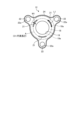
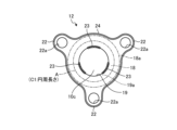
- FIG. 2 is a perspective view showing a base member included in the rotary compressor of Example 1 from above.
- FIG. 3 is a plan view showing the base member in Example 1 from below.
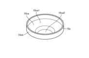
- FIG. 4 is a perspective view showing the bottom shell in Example 1 from above.
- FIG. 5 is a sectional view showing a joint portion between the bottom shell and the base member in Example 1.
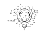
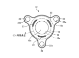
- FIG. 6 is a plan view showing a welded portion of the base member in Example 1.
- FIG. 7 is a plan view showing a comparative example for comparison with the welded portion in Example 1.
- FIG. 8 is a diagram comparing Example 1 and Comparative Example with respect to the amount of deformation of the mounting surface before and after welding.
- FIG. 1 is an external view showing a rotary compressor of Example 1.
- FIG. 2 is a perspective view showing a base member included in the rotary compressor of Example 1 from above.
- FIG. 3 is a plan view showing the base member in Example
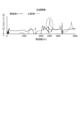
- FIG. 9 is a diagram showing a comparison between Example 1 and a comparative example regarding changes in inertance with respect to frequency.
- FIG. 10 is a plan view showing a welded portion of the base member in Example 2.
- FIG. 11 is a plan view showing a welded portion of a base member in Example 3.
- FIG. 12 is a perspective view showing the base member in Example 4 from below.
- hermetic compressor disclosed in the present application is not limited to the following examples.
- FIG. 1 is an external view showing a rotary compressor of Example 1.
- the rotary compressor 1 includes a vertical cylindrical compressor body container 10, an accumulator 11, and a base member 12 that supports the compressor body container 10. Inside the vertical cylindrical compressor body container 10, there is a compression section 14 that sucks refrigerant from the accumulator 11 through a compression section suction pipe 102 and a communication pipe 104 and discharges the compressed refrigerant into the inside of the compressor main body container 10. and a motor 15 that drives the compression section 14.
- the rotary compressor 1 is an internal high-pressure hermetic compressor that discharges the high-pressure refrigerant compressed in the compression section 14 into the compressor main body container 10 and further discharges it through the discharge pipe 107.
- the compressor main body container 10 has a cylindrical main shell 10a, a cup-shaped top shell 10b, and a cup-shaped bottom shell 10c.
- the main shell 10a, top shell 10b, and bottom shell 10c of the compressor main body container 10 are formed of a metal material.
- the compressor main body container 10 is formed by welding a top shell 10b to the upper end of the main shell 10a and welding a bottom shell 10c to the lower end of the main shell 10a.
- the accumulator 11 is fixed to the main shell 10a of the compressor main body container 10 by a fixing fitting 13.
- a base member 12 is welded to the bottom shell 10c of the compressor main body container 10.
- FIG. 2 is a perspective view showing the base member 12 included in the rotary compressor 1 of the first embodiment from above.
- FIG. 3 is a plan view showing the base member 12 in Example 1 from below.
- FIG. 4 is a perspective view showing the bottom shell 10c in Example 1 from above.
- FIG. 5 is a sectional view showing a joint portion between the bottom shell 10c and the base member 12 in the first embodiment.
- the base member 12 in this embodiment is formed in the shape of an upside-down saucer, and is formed by pressing a metal material with a thickness of T [mm], for example. formed by.
- the base member 12 has a mounting surface 18, an opening 19, and legs 22.
- the base member 12 supports the compressor body container 10 from below by placing the bottom shell 10c of the compressor body container 10 on the mounting surface 18.
- the mounting surface 18 is formed along a bottom surface portion 10ca (contact surface portion 10ca1) of the bottom shell 10c, which will be described later. This can prevent a gap from forming between the bottom shell 10c and the mounting surface 18 of the base member 12.
- the mounting surface 18 is formed into a generally annular shape by forming an opening 19 in the center, and gently slopes downward toward the center of the opening 19. There is. Since the mounting surface 18 of the base member 12 comes into contact with the bottom shell 10c, the bottom shell 10c placed on the mounting surface 18 can be supported by the entire mounting surface 18, and vibrations generated in the base member 12 can be suppressed. Furthermore, the mechanical strength of the base member 12 is increased by forming an outer peripheral side rising portion 24 extending from the outer peripheral edge of the base member 12 along the central axis direction of the opening 19. .
- a circular opening 19 is formed in the center of the mounting surface 18 of the base member 12.
- a contact surface portion 10ca1 of a bottom surface portion 10ca of a bottom shell 10c which will be described later, is in contact with an opening edge 19a of an opening 19 of the base member 12.
- the bottom shell 10c of the compressor main body container 10 is formed to have a U-shaped (cup-shaped) cross section.
- the bottom shell 10c of the embodiment includes a generally disc-shaped bottom portion 10ca and a cylindrical portion 10cb extending upward from the outer periphery of the bottom portion 10ca.
- the bottom surface portion 10ca of the bottom shell 10c slopes gently downward toward the center.
- the bottom surface portion 10ca of the bottom shell 10c includes a contact surface portion 10ca1 that is placed on the placement surface 18 of the base member 12, and a fitting portion 10ca2 that is fitted into the opening 19 of the base member 12.
- the fitting portion 10ca2 slightly protrudes downward so that the outer surface of the fitting portion 10ca2 comes into contact with the opening edge 19a of the opening 19 of the base member 12.
- a plurality of slits 21 extending in the circumferential direction of the opening 19 are formed in the mounting surface 18 of the base member 12 .
- the slit 21 is a through hole that penetrates from the upper surface to the lower surface of the mounting surface 18 of the base member 12.
- each of the plurality of slits 21 is formed at intervals on the circumference of the same circle along the circumferential direction of the opening 19.
- the three slits 21 are arranged on the circumference A (circle A) located between the outer peripheral edge 18a of the mounting surface 18 and the opening edge 19a of the opening 19 in the radial direction of the mounting surface 18.
- the circumference A in Example 1 is a circle passing near the midpoint of a line segment connecting the outer peripheral edge 18a of the mounting surface 18 and the opening edge 19a in the radial direction;
- Three slits 21 are formed on the circumference A. Further, the slits 21 are formed at equal intervals in the circumferential direction of the circumference A. Note that the position of the slits 21 in the radial direction of the mounting surface 18 and the number of slits 21 are not limited to these.
- the circumference A on which the slit 21 is located may be shifted to one side in the radial direction with respect to the circumference passing through the center between the outer circumferential edge 18a and the opening edge 19a in the radial direction of the mounting surface 18,
- the number of slits may be four or more.
- each slit 21 is formed to extend in an arc shape along the circumference A along the circumferential direction of the opening 19.
- each slit 21 is located at a position where it overlaps a leg portion 22 described later in the circumferential direction when each slit 21 is viewed from a position that is the center point of the circumference A on the central axis passing through the center of the opening 19. is formed. Note that the position and shape of the slit 21 are not limited to this.
- Each of the three slits 21 has a slit width W1 [mm] in a direction orthogonal to the circumference A along the circumferential direction of the opening 19 (in the first embodiment, the slit width W1 in the radial direction of the opening 19). It is 1.5 times or more the thickness T [mm] of the mounting surface 18 of the member 12. That is, W1 ⁇ 1.5 ⁇ T.
- the welding torch it is possible to prevent the electrode from colliding with the edge of the slit 21, and it is possible to facilitate the formation of the welded portion 23.
- the thickness T of the base member 12 on the mounting surface 18 is set to be approximately 1.7 times the slit width W1 of the slit 21.
- the slit length L1 of the opening 19 in the circumferential direction is greater than or equal to the weld length L2.
- the slit length L1 of the slit 21 is defined as the length of an arc connecting both ends of each slit 21 in the circumferential direction
- the weld length L2 of the welded part 23 is defined as the length of the arc connecting both ends of each welded part 23 in the circumferential direction. It is defined as the length of the arc connecting the parts.
- the slit length L1 of the slit 21 is defined as the straight line distance connecting both ends of each slit 21 in the circumferential direction
- the weld length L2 of the welded part 23 is defined as the straight line distance connecting both ends of each slit 21 in the circumferential direction. It may also be defined by the straight line distance.
- the electrode (not shown) of a welding torch in arc welding can be connected to the compressor main body container.
- the electrode of the welding torch can be prevented from hitting the edge of the slit 21. That is, the slit length L1 of the slit 21 in which the welding part 23 is formed is made larger (longer) than the welding length L2 while ensuring a sufficient welding length L2 to maintain the welding strength of the welding part 23. This makes it possible to improve welding workability.
- the mounting surface 18 of the base member 12 and the compressor main body container can be connected to each other through the slit 21. Since the welded portion 23 can be appropriately formed to connect the contact surface portion 10ca1 of the bottom shell 10c of No. 10, variations in the strength of joining the bottom shell 10c and the base member 12 at each welded portion 23 can be prevented. It can be prevented.
- Three leg portions 22 are integrally formed on the outer periphery of the base member 12.
- the three legs 22 are formed to extend continuously from the annular mounting surface 18 and outward in the radial direction of the opening 19 . Further, the three leg portions 22 are arranged at equal intervals in the circumferential direction of the opening 19.
- the base member 12 is supported on an installation surface (not shown) via the elastic body by attaching an elastic body (not shown) to each leg 22 .
- each leg portion 22 has a mounting hole 22a formed through the base member 12 into which an upper end portion of an elastic body (not shown) is fitted.
- the elastic body for example, a cylindrical rubber material is used.
- FIG. 6 is a plan view showing the welded portion 23 of the base member 12 in Example 1, and shows the base member 12 from below.
- a welded portion 23 is formed by arc welding through the slit 21 to connect the mounting surface 18 of the base member 12 and the bottom shell 10c.
- the bottom shell 10c of the compressor main body container 10 and the base member 12 are joined by a plurality of welded portions 23 extending a predetermined length in the circumferential direction.
- the three welds 23 are located between the outer peripheral edge 18a of the mounting surface 18 and the opening edge 19a of the opening 19 in the radial direction of the mounting surface 18. . More specifically, the three welds 23 are formed on the circumference A located between the outer circumferential edge 18a and the opening edge 19a in the radial direction, at equal intervals in the circumferential direction.
- the deformation that occurs around the welded portion 23 (slit 21) of the base member 12 due to the heat during welding is caused by the deformation of the base member 12 itself in the portions 18b on both sides of the welded portion 23 (slit 21).
- This can be effectively suppressed by rigidity. Therefore, deformation caused by welding around the welded portions 23 can be suppressed, so that each welded portion 23 connects the bottom surface of the bottom shell 10c of the compressor main body container 10 and the mounting surface 18 of the base member 12. can be joined without any gaps.
- the base member 12 resonates with the vibration of the compressor body container 10, which is a phenomenon peculiar to when there is a gap between the bottom surface of the bottom shell 10c and the mounting surface 18 of the base member 12. The occurrence of this phenomenon can be suppressed, and the generation of noise due to resonance of the base member 12 can be suppressed.
- the first embodiment does not limit the radial position of the welded portion 23 formed on the mounting surface 18, and the welded portion 23 (slit 21) is located between the outer peripheral edge 18a of the base member 12 and the opening 19. It suffices if it is formed between the opening edge 19a and the opening edge 19a. Further, the first embodiment does not limit the number of welded portions 23, and the number of welded portions 23 may be two or four or more. Further, in the first embodiment, the welded portion 23 (slit 21) is formed at a position that overlaps the leg portion 22 in the radial direction, but the position of the welded portion 23 is not limited, and the welded portion 23 (slit 21) overlaps the leg portion 22 in the radial direction. The welded portion 23 may be formed at a position where it is not necessary.
- each welded portion 23 is in contact with at least a portion of the edge of the corresponding slit 21. More specifically, each welding portion 23 connects the edge of each slit 21 on the mounting surface 18 of the base member 12 and a portion of the bottom shell 10c that overlaps each slit 21 when viewed in the axial direction. The bottom shell 10c and the mounting surface 18 of the base member 12 are joined by forming a welded portion 23 through each slit 21. Each welding portion 23 in the first embodiment is formed so as to be in contact with the outer circumferential edge of the slit 21 on the mounting surface 18 .
- the welded portion 23 when the welded portion 23 is formed through the slit 21, the welded portion 23 is in contact with at least one edge of the inner circumference side edge and the outer circumference side edge of the slit 21 on the mounting surface 18. It is sufficient if it is formed as follows.
- the welded portion 23 may be formed so as to contact only the inner peripheral edge of the slit 21 on the mounting surface 18. Further, the welded portion 23 may be formed so as to be in contact with both the inner peripheral edge and the outer peripheral edge of the slit 21 on the mounting surface 18, as in Example 3 to be described later.
- Each welded portion 23 is formed to extend a predetermined length in the circumferential direction of the opening 19.
- the length of the circular arc connecting both ends of the welding portion 23 along the circumferential direction of the opening 19 is defined as the welding length L2 of each welding portion 23.
- the circumferential length of a circle (circumference A) passing through the slit 21 in the radial direction of the mounting surface 18 is defined as C1.
- the arc indicating the welding length L2 is located on the same circumference as the circumference A.
- the welding length L2 of each welding part 23 is a ratio of 5% or more to the circumferential length C1 of the circumference A along the circumferential direction of the opening 19 (L2/C1 ⁇ 0.05). It is desirable that thereby, each welded portion 23 is formed with a welding length L2 sufficient to prevent rattling in the circumferential direction, so that the bonding strength between the bottom shell 10c and the mounting surface 18 can be appropriately ensured.
- Example 1 as an example, the center of the weld width W2 of the weld portion 23 is located on the circumference A at a radius r [mm] from the center of the opening 19.
- the ratio of the weld length L2 of the welding part 23 to the circumferential length C1 of the circumference A is approximately 10. [%] (L2/C1 ⁇ 0.1).
- each welded portion 23 in the first embodiment is formed such that the slit length L1 of the slit 21 is longer than the welded length L2.
- the welded portion 23 is formed at both ends of each corresponding slit 21. It is formed so that it does not reach .
- the slit length L1 is larger than the welding length L2 (L1>L2).
- the first embodiment does not limit the slit length L1 of the slit 21, and the slit length L1 may be made equal to the welding length L2 so that the entire slit 21 is covered with the welded portion 23.
- each welded portion 23 through each slit 21 distant from the opening 19 of the base member 12 is formed at a position distant from the opening edge 19a of the opening 19. Therefore, portions 18b of the mounting surface 18 of the base member 12 are secured on both sides of the inner diameter side and the outer diameter side of the welded portion 23 in the radial direction of the mounting surface 18 (direction of the welding width W2).
- the base member 12 is deformed so as to expand around the welded portion 23 due to the heat applied during welding.
- the mounting surface 18 is left so as to surround the welded portion 23 (slit 21), so that the mounting surface 18 has high rigidity around the slit 21. Furthermore, in the first embodiment, since the mounting surface 18 is left so as to surround the slit 21 (welded portion 23), stress generated on the mounting surface 18 near the welded portion 23 due to heat during welding is reduced. are canceled out around the slit 21. Therefore, in the base member 12, the vicinity of the opening 19 is prevented from deforming along the opening edge 19a due to the heat applied to the welded portion 23 during welding, and the adjacent welded portions 22 on the mounting surface 18 are prevented from being deformed along the opening edge 19a due to the heat applied during welding. This prevents the portion between the two from deforming.
- the bottom shell 10c is in contact with the edge of the opening 19 of the base member 12.
- the edge of the opening 19 of the base member 12 is pressed down by the bottom shell 10c, so the strength around the edge of the opening 19 in the base member 12 is increased, and the base member 12 is deformed by the heat during welding. can be suppressed.
- the bottom shell 10c comes into contact with the edge of the opening 19 of the base member 12, it is possible to prevent a gap from forming between the edge of the opening 19 in the base member 12 and the bottom shell 10c. Vibration of the base member 12 when a gap occurs between the base member 12 and the main body container 10 can be avoided.
- the welded portion 23 is formed so as to ride on the outer peripheral edge of the slit 21 on the mounting surface 18 by about 1 mm.
- the welded portion 23 is formed to reliably connect the edge of the slit 21 in the base member 12 and the bottom shell 10c, thereby increasing the joint strength by welding and preventing the base member 12 from deforming due to the heat during welding. can be suppressed.
- This can prevent a gap from forming between the edge of the slit 21 in the base member 12 and the bottom shell 10c, and prevent vibration of the base member 12 when a gap occurs between the edge of the slit 21 in the base member 12 and the bottom shell 10c. It will be done.
- the welded portion 23 in Example 1 was formed to extend in an arc shape along the outer peripheral edge of the slit 21, for example, the welded portion 23 may be formed to extend in a straight line touching the outer peripheral edge of the slit 21. may be done.
- the welded portion 23 in Example 1 is formed by arc welding through the slit 21, the welded portion 23 is not limited to being formed by arc welding.
- Each welded portion 23 may be formed by a welding method that does not use the slit 21, for example, by laser welding or projection welding.
- the slit 21 does not need to be formed on the mounting surface 18 of the base member 12, and the plurality of welded parts 23 are connected to the outer peripheral edge 18a of the base member 12 and the opening of the opening 19. It suffices if it is formed between the edge 19a and the edge 19a.
- FIG. 7 is a plan view showing a comparative example for comparison with the welded portion 23 in Example 1.
- FIG. 8 shows that on the mounting surface 18 of the base member 12, a portion located on the circumference A at a certain distance r [mm] from the center of the opening 19 is located on the compressor 1 before and after the welding portion 23 is formed.
- 9 is a diagram showing a comparison of the amount of deformation in the central axis direction between Example 1 shown in FIG. 7 and the comparative example shown in FIG. 8.
- the circumference A here is the circumference of the circle in which the outer peripheral edge of the slit 21 is located in the first embodiment shown in FIG.
- FIG. 9 is a diagram showing a comparison between Example 1 and a comparative example regarding changes in inertance with respect to frequency.
- the three welds 23 in the comparative example extend a predetermined length in the circumferential direction of the opening 19 and are formed at equal intervals, similarly to the first embodiment. Moreover, each welding part 23 in the comparative example is formed so that the welding length extending in the circumferential direction of the opening 19 is equal to the welding length L2 of the welding part 23 in Example 1.
- the comparative example differs from Example 1 in that the three welded parts 23 are arranged along the opening edge 19a of the opening 19, and the welded parts 23 are formed at positions away from the opening edge 19a. different.
- Example 1 the distance from the center of the opening 19 is r [mm] when compared before and after welding the bottom shell 10c and the base member 12 (formation of the welded part 23). There is almost no deformation in the central axis direction of the portion of the mounting surface 18 located on the circumference A, and deformation near the edge of the opening 19 in the base member 12 before and after welding is sufficiently suppressed. .
- the distance from the center of the opening 19 is r [mm] when comparing before and after welding the bottom shell 10c and the base member 12 (formation of the welded part 23).
- the amount of deformation of the portion of the mounting surface 18 located in the central axis direction is at least three times that of the example.
- on the mounting surface 18 on the circumference A there are parts that are significantly deformed in the direction of the rotation axis and parts that are hardly deformed in the direction of the rotation axis, and as a result, the base member 12
- the mounting surface 18 is deformed in a wavy manner before and after welding. Therefore, when the welded portion 23 is formed along the opening 19 as in the comparative example, a gap is likely to occur between the bottom shell 10c and the mounting surface 18 of the base member 12.
- the compressor It is possible to prevent a gap from being generated between the bottom shell 10c of the main container 10 and the mounting surface 18 of the base member 12 due to deformation due to welding. Therefore, in the first embodiment, the occurrence of vibration of the base member 12 due to the gap between the compressor main body container 10 and the base member 12 is suppressed.
- Example 1 and Comparative Example when welding the base member 12 and the bottom shell 10c (forming the welded part 23), the base member 12 expands around the welded part 23 due to the heat added during welding. It is thought that it will deform as follows.
- the welded portion 23 is formed along the opening 19, the portion near the opening edge 19a of the opening 19 of the base member 12 is in the welded portion 23 (for example, the first It expands in a direction away from the welded portion 231). Further, also around another weld 23 (for example, second weld 232), a portion near the opening edge 19a of the opening 19 of base member 12 is located at the weld 23 (second weld 232) in the circumferential direction of the 232). As a result, the base member 12 is compressed from both of the two circumferentially adjacent welds 23 (first weld 231, second weld 232) toward the intermediate position between the two welds 23. Due to the force applied to the mounting surface 18, the mounting surface 18 becomes wrinkled at the intermediate position between the two welded portions 23.
- the mounting surface 18 is left so as to surround the welded portion 23 (slit 21), so that the rigidity of the mounting surface 18 around the slit 21 is increased. is high. Furthermore, in the first embodiment, since the mounting surface 18 is left so as to surround the slit 21 (welded portion 23), the deformation that occurs in the mounting surface 18 near the welded portion 23 due to the heat during welding is prevented. are canceled out around the slit 21. For these reasons, it is presumed that, in the base member 12 in Example 1, the portion between the adjacent welded portions 23 on the mounting surface 18 is prevented from deforming due to the heat during welding.
- the transfer function shown in FIG. 9 represents the response to the excitation force at each frequency in Example 1 and the comparative example, and is shown as an inertance distribution at each frequency.
- inertance is the ratio of the force (excitation force) F [N] input to the object and the acceleration a [m/s 2 ] generated in the object due to the force, a/F [(m/s 2 )/N]. Therefore, a small inertance at a particular frequency indicates that a member to which an excitation force is applied at that frequency is less likely to resonate. On the other hand, a large inertance at a specific frequency indicates that resonance is likely to occur with the excitation force at that frequency. In FIG.
- Example 1 is shown by a solid line
- Comparative Example is shown by a broken line.
- the experimental data shown in FIG. 9 is data measured using the rotary compressor 1 in which the accumulator 11 is attached to the compressor main body container 10, as shown in FIG.
- Example 1 the inertance, which is correlated with noise, is reduced compared to the comparative example near the circled area of 2500 [Hz], and the vibration of the compressor main body container 10 is reduced. Accordingly, resonance occurring in the base member 12 is suppressed.
- the welded portion 23 is formed between the outer peripheral edge 18a of the mounting surface 18 and the opening edge 19a of the opening 19
- the welded portion 23 is formed along the opening edge 19a of the opening 19.
- the noise caused by the resonance of the base member 12 can be reduced.
- Example 1 noise due to resonance of the base member 12 near 2500 [Hz] is reduced compared to the comparative example.
- the opening 19 into which the center portion of the bottom shell 10c is fitted is formed in the center of the mounting surface 18 of the base member 12, and the base member 12 It is joined to the compressor main body container 10 by a plurality of welded portions 23 formed at intervals S1 in the circumferential direction of the compressor body 19 .
- the plurality of welded portions 23 are formed to extend a predetermined length in the circumferential direction of the opening 19 and are located between the outer peripheral edge 18 a of the mounting surface 18 and the opening edge 19 a of the opening 19 .
- portions of the mounting surface 18 are secured on both sides of the welded portion 23 in the radial direction of the mounting surface 18, so that the deformation that occurs in the base member 12 due to the heat during welding is reduced by the rigidity of the base member 12 itself. It can be suppressed by using In particular, in the first embodiment, since the mounting surface 18 is left so as to surround the welding part 23 (slit 21), stress generated on the mounting surface 18 near the welding part 23 due to the heat during welding. are canceled out around the slit 21, and deformation of the mounting surface 18 can be suppressed. Therefore, the portion of the mounting surface 18 of the base member 12 located on the inner peripheral side of the slit 21 and the bottom shell 10c can be joined without any gap while being in contact with each other. As a result, the resonance of the base member 12 due to the vibration of the compressor main body container 10 is suppressed, and the generation of noise due to the resonance of the base member 12 can be suppressed.
- the mounting surface 18 of the base member 12 in the rotary compressor 1 of Example 1 is formed along the bottom shell 10c of the compressor main body container 10, and the mounting surface 18 of the base member 12 is in contact with the bottom shell 10c. It is in contact with the surface portion 10ca1. This prevents the generation of a gap between the bottom shell 10c placed on the mounting surface 18 and the mounting surface 18, and suppresses vibrations occurring in the base member 12. Further, in the first embodiment, the bottom shell 10c is in contact with the opening edge 19a of the opening 19 of the base member 12.
- the opening edge 19a of the opening 19 of the base member 12 is pressed by the bottom shell 10c, so the mechanical strength around the edge of the opening 19 in the base member 12 is increased, and the heat during welding causes the base member 1 deformation can be suppressed. Furthermore, it is possible to prevent a gap from forming between the edge of the opening 19 in the base member 12 and the bottom shell 10c, and vibrations caused by resonance of the base member 12 can be suppressed.
- the weld width W2 of the weld portion 23 is the width of the weld portion 23 in the direction (radial direction) orthogonal to the weld length L2 direction (circumferential direction).
- the welding length L2 of each of the plurality of welding parts 23 is the circumferential length C1 of the circumference A.
- the ratio is 5% or more.
- the plurality of welded portions 23 are arranged on the same circumference ( It is formed along the circumference A).
- the portions 18b of the mounting surface 18 are secured on both sides of the welded portion 23 in the radial direction of the mounting surface 18, so that the deformation that occurs in the base member 12 due to the heat during welding is prevented from deforming the base member 12 itself.
- This can be effectively suppressed by rigidity. Therefore, the base member 12 and the bottom shell 10c can be joined without any gaps. As a result, the resonance of the base member 12 is effectively suppressed, and the generation of noise due to the resonance of the base member 12 can be effectively suppressed.
- the base member 12 of the rotary compressor 1 of the first embodiment has a plurality of slits 21 extending in the circumferential direction of the opening 19 through the mounting surface 18 in the same circular shape along the circumferential direction of the opening 19. They are formed at intervals on the circumference A.
- Each welded portion 23 is formed through each slit 21 and is formed so as to be in contact with the edge of each slit 21. Thereby, the joint strength of each welded portion 23 can be increased.
- each of the plurality of slits 21 has a slit width W1 perpendicular to the circumferential direction of the opening 19 (in the radial direction of the opening 19) on the mounting surface. It is 1.5 times or more the thickness T of the base member 12 at 18 (W1 ⁇ 1.5 ⁇ T).
- the slit length L1 in the circumferential direction of the opening 19 is longer than the weld length L2 in which each of the plurality of welds 23 extends in the circumferential direction of the opening 19. is also large (L1>L2).
- each of the plurality of welded portions 23 is in contact with at least one edge of the inner circumference side edge and the outer circumference side edge of the slit 21. It is formed like this. Thereby, the base member 12 and the bottom shell 10c can be joined without any gaps while being in contact with each other, and the joint strength of each welded portion 23 can be increased.
- FIG. 10 is a plan view showing the welded portion 23 of the base member 12 in Example 2.
- FIG. 11 is a plan view showing the welded portion 23 of the base member 12 in Example 3. Examples 2 and 3 differ from Example 1 in the position where the welded portion 23 in the slit 21 is formed.
- the shape of the slit 21 formed in the base member 12 has a so-called half-moon cross section (semi-circle shape) having an arcuate outer peripheral edge and a linear inner peripheral edge. is formed.
- the curvature of the arc on the outer peripheral side of the slit 21 is, for example, smaller than the curvature of the circumference A along the circumferential direction of the opening 19.
- a straight line along the inner peripheral edge of the slit 21 is formed parallel to a straight line tangent to the circumference A.
- each welded portion 23 in Example 2 is formed along the outer edge of the slit 21 between the outer edge and the inner edge of the slit 21. . Moreover, each welding part 23 is formed so as to straddle the outer peripheral side edge of the slit 21 on the mounting surface 18 and the bottom shell 10c exposed from the slit 21. As a result, when performing arc welding through the slit 21, the welding portion 23 can be properly formed to connect the base member 12 and the compressor main body container 10, so that the base member 12 and the bottom shell 10c can be connected to each other. They can be joined without any gaps when they are in contact with each other.
- the electrode of a welding torch (not shown) can be connected to the bottom shell of the compressor main body container 10 during welding (when forming the welding portion 23).
- the contact portion between the base member 10c and the mounting surface 18 of the base member 12 can be smoothly approached, and manufacturing can be facilitated.
- each of the welded portions 23 is located between the outer peripheral edge 18a of the mounting surface 18 and the opening edge 19a of the opening 19, so that the opening 19 is Deformation between adjacent welded portions 23 in the circumferential direction during welding is suppressed. Therefore, it is possible to prevent a gap from being generated between the bottom surface 10d of the bottom shell 10c of the compressor main body container 10 and the mounting surface 18 of the base member 12 during welding, so that the base member 12 due to vibrations of the compressor main container 10 can be prevented. resonance is suppressed.
- each welded portion 23 spans both the inner and outer edges of the slit 21 in the radial direction of the mounting surface 18, and extends in the circumferential direction of the opening 19. It is formed across both ends of the slit 21. That is, the welded portion 23 is formed to cover the entire slit 21.
- the plurality of welded portions 23 are formed to extend in the circumferential direction of the opening 19 by a predetermined welding length L2, and the plurality of welded portions 23 are 23 is located between the outer peripheral edge 18a of the mounting surface 18 and the opening edge 19a of the opening 19, thereby suppressing deformation between adjacent welding parts 23 in the circumferential direction of the opening 19 during welding. Therefore, resonance of the base member 12 due to vibration of the compressor main body container 10 is suppressed, and noise due to resonance of the base member 12 is suppressed.
- FIG. 12 is a perspective view showing the base member 12 in Example 4 from below.
- Embodiment 4 has the following advantages: the slit 21 is not formed on the mounting surface 18 of the base member 12, the inner peripheral side rising portion 25 is formed on the edge 19a of the opening 19 of the base member 12, and the base This is the same as in Example 1 except that the member 12 and the bottom shell 10c have a welded portion 23 welded by a welding method that does not involve a slit (for example, projection welding, laser welding, etc.).
- a cylindrical inner peripheral side rising portion 25 is integrally formed on the opening edge 19a of the opening 19 of the base member 12 in Example 4 by, for example, burring.
- the inner peripheral side rising portion 25 protrudes to the side opposite to the bottom surface 10d of the bottom shell 10c so as not to contact the bottom surface 10d of the bottom shell 10c.
- the base member 12 has increased rigidity near the opening edge 19a of the opening 19, so that the rigidity of the base member 12 is increased between adjacent welded portions 23 in the circumferential direction of the opening 19. Deformation caused by heat during welding can be further suppressed.
- the base member 12 of the fourth embodiment has the bottom shell 10c on the mounting surface 18 instead of the slit 21 formed therein.
- a plurality of convex portions (not shown) for forming the weld portion 23 may be formed at the position of the weld portion 23 on the contacting side.
- a plurality of convex portions (not shown) for forming the welded portion 23 may be formed on the bottom surface 10d of the bottom shell 10c of the compressor main body container 10. .
- Rotary compressor (hermetic compressor) 10 Compressor main body container 11 Accumulator 12 Base member 14 Compression part 15 Motor 18 Placement surface 18a Outer periphery 19 Opening 19a Opening edge 21 Slit 23 Welded part 25 Inner peripheral side rising part A Circumference (circle) C1 Circumference length L1 Slit length L2 Welding length W1 Slit width W2 Welding width
Landscapes
- Engineering & Computer Science (AREA)
- Mechanical Engineering (AREA)
- General Engineering & Computer Science (AREA)
- Applications Or Details Of Rotary Compressors (AREA)
- Compressor (AREA)
Abstract
Description
図1は、実施例1のロータリ圧縮機を示す外観図である。図1に示すように、ロータリ圧縮機1は、縦型円筒状の圧縮機本体容器10と、アキュムレータ11と、圧縮機本体容器10を支持するベース部材12と、を備える。縦型円筒状の圧縮機本体容器10の内部には、圧縮部吸入管102および連絡管104を通してアキュムレータ11から冷媒を吸入して圧縮した冷媒を圧縮機本体容器10の内部に吐出する圧縮部14と、圧縮部14を駆動するモータ15と、が収容されている。ロータリ圧縮機1は、圧縮部14で圧縮された高圧冷媒を圧縮機本体容器10の内部に吐出し、さらに吐出管107を通して吐出する内部高圧型の密閉型圧縮機である。
図2は、実施例1のロータリ圧縮機1が備えるベース部材12を上側から示す斜視図である。図3は、実施例1におけるベース部材12を下側から示す平面図である。図4は、実施例1におけるボトムシェル10cを上側から示す斜視図である。図5は、実施例1におけるボトムシェル10cとベース部材12との接合部分を示す断面図である。
また、ベース部材12の載置面18には、開口部19の周方向に延びる複数のスリット21が形成されている。スリット21は、ベース部材12の載置面18における上面から下面へと貫通する貫通孔である。また、複数のスリット21のそれぞれは、開口部19の周方向に沿う同一円の円周上に間隔をあけて形成されている。本実施例1では、3つのスリット21が、載置面18の径方向において載置面18の外周縁18aと開口部19の開口縁19aとの間に位置する円周A(円A)上に位置している。具体的には、実施例1での円周Aは、載置面18の外周縁18aと開口縁19aとを径方向に結んだ線分の中点近傍を通る円とされており、この円周A上に3つのスリット21が形成されている。また、スリット21は円周Aの周方向に対して等間隔に形成されている。なお、載置面18の径方向におけるスリット21の位置や、スリット21の個数はこれに限定されるものではない。例えば、スリット21が位置する円周Aは、載置面18の径方向において外周縁18aと開口縁19aとの間の中心を通る円周に対して径方向の一方側にずれてもよく、スリットの個数は4つ以上であってもよい。
図6は、実施例1におけるベース部材12の溶接部23を示す平面図であり、ベース部材12を下側から示している。図5、図6に示すように、実施例1では、例えば、スリット21を介したアーク溶接によって、ベース部材12の載置面18とボトムシェル10cとを繋ぐように溶接部23が形成される。周方向に所定の長さで延びる複数の溶接部23によって、圧縮機本体容器10のボトムシェル10cとベース部材12とが接合されている。
図7は、実施例1における溶接部23と比較する比較例を示す平面図である。図8は、ベース部材12の載置面18において、開口部19の中心から一定の距離r[mm]離れた円周A上に位置する部分が、溶接部23の形成前後で圧縮機1の中心軸方向にどのように変形したかの変形量を、図7に示した実施例1と、図8に示した比較例とで比較して示す図である。なお、ここでの円周Aは、図6に示す実施例1においてスリット21の外周側の縁部が位置する円の円周としている。図9は、周波数に対するイナータンスの変化について実施例1と比較例を比較して示す図である。
上述したように実施例1のロータリ圧縮機1において、ベース部材12の載置面18の中央には、ボトムシェル10cの中央部が嵌め込まれる開口部19が形成され、ベース部材12が、開口部19の周方向に間隔S1をあけて形成された複数の溶接部23によって圧縮機本体容器10と接合される。複数の溶接部23は、開口部19の周方向に所定長さだけ延びて形成され、載置面18の外周縁18aと開口部19の開口縁19aとの間に位置する。これにより、載置面18の径方向における溶接部23の両側に、載置面18の部分がそれぞれ確保されるので、溶接時の熱でベース部材12に生じる変形が、ベース部材12自身の剛性を利用して抑えられる。特に、本実施例1では、溶接部23(スリット21)の周りを取り囲むように載置面18が残されていることにより、溶接時の熱によって溶接部23近傍の載置面18に生じる応力がスリット21周りで相殺され、載置面18の変形を抑えることができる。そのため、ベース部材12の載置面18におけるスリット21の内周側に位置する部分とボトムシェル10cとを、相互に接触させた状態で隙間なく接合することができる。その結果、圧縮機本体容器10の振動に伴うベース部材12の共振が抑えられ、ベース部材12の共振による騒音の発生を抑えることができる。
10 圧縮機本体容器
11 アキュムレータ
12 ベース部材
14 圧縮部
15 モータ
18 載置面
18a 外周縁
19 開口部
19a 開口縁
21 スリット
23 溶接部
25 内周側立ち上がり部
A 円周(円)
C1 円周長さ
L1 スリット長さ
L2 溶接長さ
W1 スリット幅
W2 溶接幅
Claims (10)
- 縦置き筒状の圧縮機本体容器と、前記圧縮機本体容器内に配置されて冷媒を圧縮する圧縮部と、前記圧縮機本体容器内に配置されて前記圧縮部を駆動するモータと、を備える密閉型圧縮機であって、
前記圧縮機本体容器に溶接されて前記圧縮機本体容器を支持するベース部材を備え、
前記圧縮機本体容器は、ボトムシェルを有し、
前記ベース部材は、前記ボトムシェルが載せられる載置面を有し、
前記載置面の中央には、前記ボトムシェルの中央部が嵌め込まれる開口部が形成され、
前記ベース部材は、前記開口部の周方向に間隔をあけて形成された複数の溶接部によって前記ボトムシェルと接合され、
前記複数の溶接部は、前記開口部の周方向に所定長さだけ延びて形成されるとともに、前記載置面の外周縁と前記開口部の開口縁との間に位置する、密閉型圧縮機。 - 前記複数の溶接部は、前記開口部の周方向に沿う同一円の円周上に配置されている、
請求項1に記載の密閉型圧縮機。 - 前記溶接部の両端部を前記周方向に沿って結ぶ円弧の長さを溶接長さL2[mm]とし、前記円弧と重なる円周の周長を円周長さC1[mm]としたとき、
前記複数の溶接部の各々の前記溶接長さL2と前記円周長さC1とは、
L2/C1≧0.05・・・(式1)
を満たす、
請求項1または2に記載の密閉型圧縮機。 - 前記ベース部材には、前記載置面を貫通して前記開口部の周方向に延びる複数のスリットが形成され、
前記溶接部は、前記スリットを介して形成されるとともに、前記スリットの縁部に接する、
請求項1ないし3のいずれか1項に記載の密閉型圧縮機。 - 前記複数のスリットの各々は、前記開口部の周方向に直交する方向のスリット幅をW1とし、前記載置面における前記ベース部材の厚さをベース部材厚さTとしたとき、前記スリット幅W1[mm]と前記ベース部材厚さT[mm]とは、
W1≧1.5×T・・・(式2)
を満たす、
請求項4に記載の密閉型圧縮機。 - 前記スリットの両端部を前記周方向に沿って結ぶ円弧の長さをスリット長さL1[mm]とし、前記溶接部の両端部を前記周方向に沿って結ぶ円弧の長さを溶接長さL2[mm]としたとき、
前記複数のスリットの各々の前記スリット長さL1と、前記複数の溶接部の各々の前記溶接長さL2とは、
L1>L2・・・(式3)
を満たす、
請求項4または5に記載の密閉型圧縮機。 - 前記複数の溶接部の各々は、前記スリットの内周側の縁部と外周側の縁部の少なくとも一方側の縁部に乗り上げるように形成される、
請求項4ないし6のいずれか1項に記載の密閉型圧縮機。 - 前記ベース部材の前記開口部の開口縁は、前記ボトムシェルに接触する
請求項1ないし7のいずれか1項に記載の密閉型圧縮機。 - 前記載置面は、前記ボトムシェルに沿って形成され、前記ボトムシェルと接触する、
請求項1ないし8のいずれか1項に記載の密閉型圧縮機。 - 前記ベース部材の前記開口部の開口縁には、前記ボトムシェルとは反対側に突出する筒状の立ち上がり部が形成される、
請求項1ないし9のいずれか1項に記載の密閉型圧縮機。
Priority Applications (2)
| Application Number | Priority Date | Filing Date | Title |
|---|---|---|---|
| CN202380026193.5A CN118843746A (zh) | 2022-03-24 | 2023-02-24 | 密闭型压缩机 |
| US18/844,709 US12560157B2 (en) | 2022-03-24 | 2023-02-24 | Sealed compressor |
Applications Claiming Priority (2)
| Application Number | Priority Date | Filing Date | Title |
|---|---|---|---|
| JP2022049121A JP7476919B2 (ja) | 2022-03-24 | 2022-03-24 | 密閉型圧縮機 |
| JP2022-049121 | 2022-03-24 |
Publications (1)
| Publication Number | Publication Date |
|---|---|
| WO2023181785A1 true WO2023181785A1 (ja) | 2023-09-28 |
Family
ID=88100515
Family Applications (1)
| Application Number | Title | Priority Date | Filing Date |
|---|---|---|---|
| PCT/JP2023/006876 Ceased WO2023181785A1 (ja) | 2022-03-24 | 2023-02-24 | 密閉型圧縮機 |
Country Status (4)
| Country | Link |
|---|---|
| US (1) | US12560157B2 (ja) |
| JP (1) | JP7476919B2 (ja) |
| CN (1) | CN118843746A (ja) |
| WO (1) | WO2023181785A1 (ja) |
Families Citing this family (2)
| Publication number | Priority date | Publication date | Assignee | Title |
|---|---|---|---|---|
| JP2024064575A (ja) * | 2022-10-28 | 2024-05-14 | 株式会社富士通ゼネラル | 圧縮機 |
| US12270398B1 (en) * | 2023-12-26 | 2025-04-08 | Copeland Lp | Compressor assemblies including lower covers having mounting feet skirts configured for increasing mounting feet stiffness and resistance to crack formation |
Citations (9)
| Publication number | Priority date | Publication date | Assignee | Title |
|---|---|---|---|---|
| JPS6143982U (ja) * | 1984-08-27 | 1986-03-22 | 株式会社東芝 | 圧縮機 |
| JPS6413284U (ja) * | 1987-07-13 | 1989-01-24 | ||
| JPH09329081A (ja) * | 1996-06-12 | 1997-12-22 | Toshiba Corp | 圧縮機 |
| JPH1037885A (ja) * | 1996-07-23 | 1998-02-13 | Toshiba Corp | コンプレッサとコンプレッサの製造方法 |
| JPH11324922A (ja) * | 1998-05-14 | 1999-11-26 | Matsushita Electric Ind Co Ltd | 密閉型圧縮機 |
| CN100455795C (zh) * | 2004-06-28 | 2009-01-28 | 乐金电子(天津)电器有限公司 | 具有噪声降低结构的密封型压缩机 |
| JP2013019302A (ja) * | 2011-07-11 | 2013-01-31 | Daikin Industries Ltd | 圧縮機の取付脚、圧縮機及び圧縮機の製造方法 |
| JP2014100718A (ja) * | 2012-11-19 | 2014-06-05 | Mitsubishi Heavy Ind Ltd | 補強方法および補強構造 |
| JP2014140873A (ja) * | 2013-01-24 | 2014-08-07 | Hiruta Kogyo Co Ltd | 重ね合わせ溶接 |
Family Cites Families (6)
| Publication number | Priority date | Publication date | Assignee | Title |
|---|---|---|---|---|
| JPS6143982A (ja) | 1984-08-07 | 1986-03-03 | Yamato Scient Co Ltd | 連続流動式ホモジナイザ |
| US4946351A (en) * | 1989-06-14 | 1990-08-07 | Tecumseh Products Company | Compressor mounting system |
| JP3389539B2 (ja) * | 1999-08-31 | 2003-03-24 | 三洋電機株式会社 | 内部中間圧型2段圧縮式ロータリコンプレッサ |
| JP5286937B2 (ja) * | 2008-05-27 | 2013-09-11 | 株式会社富士通ゼネラル | ロータリ圧縮機 |
| CN107110163B (zh) * | 2015-01-13 | 2019-01-11 | 富士通将军股份有限公司 | 旋转式压缩机 |
| JP6897811B1 (ja) | 2020-01-30 | 2021-07-07 | 株式会社富士通ゼネラル | ロータリ圧縮機 |
-
2022
- 2022-03-24 JP JP2022049121A patent/JP7476919B2/ja active Active
-
2023
- 2023-02-24 US US18/844,709 patent/US12560157B2/en active Active
- 2023-02-24 WO PCT/JP2023/006876 patent/WO2023181785A1/ja not_active Ceased
- 2023-02-24 CN CN202380026193.5A patent/CN118843746A/zh active Pending
Patent Citations (9)
| Publication number | Priority date | Publication date | Assignee | Title |
|---|---|---|---|---|
| JPS6143982U (ja) * | 1984-08-27 | 1986-03-22 | 株式会社東芝 | 圧縮機 |
| JPS6413284U (ja) * | 1987-07-13 | 1989-01-24 | ||
| JPH09329081A (ja) * | 1996-06-12 | 1997-12-22 | Toshiba Corp | 圧縮機 |
| JPH1037885A (ja) * | 1996-07-23 | 1998-02-13 | Toshiba Corp | コンプレッサとコンプレッサの製造方法 |
| JPH11324922A (ja) * | 1998-05-14 | 1999-11-26 | Matsushita Electric Ind Co Ltd | 密閉型圧縮機 |
| CN100455795C (zh) * | 2004-06-28 | 2009-01-28 | 乐金电子(天津)电器有限公司 | 具有噪声降低结构的密封型压缩机 |
| JP2013019302A (ja) * | 2011-07-11 | 2013-01-31 | Daikin Industries Ltd | 圧縮機の取付脚、圧縮機及び圧縮機の製造方法 |
| JP2014100718A (ja) * | 2012-11-19 | 2014-06-05 | Mitsubishi Heavy Ind Ltd | 補強方法および補強構造 |
| JP2014140873A (ja) * | 2013-01-24 | 2014-08-07 | Hiruta Kogyo Co Ltd | 重ね合わせ溶接 |
Also Published As
| Publication number | Publication date |
|---|---|
| JP7476919B2 (ja) | 2024-05-01 |
| US12560157B2 (en) | 2026-02-24 |
| JP2023142291A (ja) | 2023-10-05 |
| CN118843746A (zh) | 2024-10-25 |
| US20250237209A1 (en) | 2025-07-24 |
Similar Documents
| Publication | Publication Date | Title |
|---|---|---|
| WO2023181785A1 (ja) | 密閉型圧縮機 | |
| US10465672B2 (en) | Actuator support structure and pump device | |
| JP2011519403A (ja) | 剪断ハブアイソレータ | |
| CN103317990B (zh) | 车辆悬架用上支架 | |
| JP7175860B2 (ja) | 圧縮機及び空調装置 | |
| KR20120126077A (ko) | 가스 발생기 | |
| JP2009185651A (ja) | オイルパン | |
| KR20050043938A (ko) | 밀폐형 압축기 | |
| CN110719009B (zh) | 弹性部件结构体及适用其的线性振动马达 | |
| JP2025132583A (ja) | 圧縮機 | |
| JP2024064575A (ja) | 圧縮機 | |
| CN113669398B (zh) | 脚垫组件、压缩机和冰箱 | |
| JP2015052432A (ja) | 室外機 | |
| JP2000291711A (ja) | 緩衝ワッシャ及び緩衝構造 | |
| KR102329102B1 (ko) | 탄성부재, 이를 구비한 선형 진동발생장치 | |
| JP3452517B2 (ja) | ストラットマウントインシュレータ | |
| JP2001059478A (ja) | 圧縮機の支持装置 | |
| JP4395013B2 (ja) | 密閉型圧縮機 | |
| JP2006342847A (ja) | ダイナミックダンパ | |
| JP4975143B2 (ja) | スピーカの振動系支持機構 | |
| JP7648571B2 (ja) | アッパーマウント及びこのアッパーマウントの組立方法 | |
| JP4189763B2 (ja) | スクロール圧縮機 | |
| JP7810607B2 (ja) | 防振装置 | |
| JP2025072028A (ja) | ダイナミックダンパ | |
| JP4668300B2 (ja) | スクロール圧縮機の組み立て方法 |
Legal Events
| Date | Code | Title | Description |
|---|---|---|---|
| 121 | Ep: the epo has been informed by wipo that ep was designated in this application |
Ref document number: 23774384 Country of ref document: EP Kind code of ref document: A1 |
|
| WWE | Wipo information: entry into national phase |
Ref document number: 18844709 Country of ref document: US |
|
| WWE | Wipo information: entry into national phase |
Ref document number: 202380026193.5 Country of ref document: CN |
|
| WWE | Wipo information: entry into national phase |
Ref document number: 2401005848 Country of ref document: TH |
|
| NENP | Non-entry into the national phase |
Ref country code: DE |
|
| 122 | Ep: pct application non-entry in european phase |
Ref document number: 23774384 Country of ref document: EP Kind code of ref document: A1 |
|
| WWP | Wipo information: published in national office |
Ref document number: 18844709 Country of ref document: US |
|
| WWG | Wipo information: grant in national office |
Ref document number: 18844709 Country of ref document: US |