WO2023181704A1 - 固体電解質、二次電池及びその製造方法 - Google Patents
固体電解質、二次電池及びその製造方法 Download PDFInfo
- Publication number
- WO2023181704A1 WO2023181704A1 PCT/JP2023/004817 JP2023004817W WO2023181704A1 WO 2023181704 A1 WO2023181704 A1 WO 2023181704A1 JP 2023004817 W JP2023004817 W JP 2023004817W WO 2023181704 A1 WO2023181704 A1 WO 2023181704A1
- Authority
- WO
- WIPO (PCT)
- Prior art keywords
- solid electrolyte
- electrode layer
- positive electrode
- negative electrode
- secondary battery
- Prior art date
- Legal status (The legal status is an assumption and is not a legal conclusion. Google has not performed a legal analysis and makes no representation as to the accuracy of the status listed.)
- Ceased
Links
Images





Classifications
-
- C—CHEMISTRY; METALLURGY
- C01—INORGANIC CHEMISTRY
- C01D—COMPOUNDS OF ALKALI METALS, i.e. LITHIUM, SODIUM, POTASSIUM, RUBIDIUM, CAESIUM, OR FRANCIUM
- C01D15/00—Lithium compounds
- C01D15/04—Halides
-
- C—CHEMISTRY; METALLURGY
- C01—INORGANIC CHEMISTRY
- C01G—COMPOUNDS CONTAINING METALS NOT COVERED BY SUBCLASSES C01D OR C01F
- C01G15/00—Compounds of gallium, indium or thallium
-
- H—ELECTRICITY
- H01—ELECTRIC ELEMENTS
- H01B—CABLES; CONDUCTORS; INSULATORS; SELECTION OF MATERIALS FOR THEIR CONDUCTIVE, INSULATING OR DIELECTRIC PROPERTIES
- H01B1/00—Conductors or conductive bodies characterised by the conductive materials; Selection of materials as conductors
- H01B1/06—Conductors or conductive bodies characterised by the conductive materials; Selection of materials as conductors mainly consisting of other non-metallic substances
-
- H—ELECTRICITY
- H01—ELECTRIC ELEMENTS
- H01M—PROCESSES OR MEANS, e.g. BATTERIES, FOR THE DIRECT CONVERSION OF CHEMICAL ENERGY INTO ELECTRICAL ENERGY
- H01M10/00—Secondary cells; Manufacture thereof
- H01M10/05—Accumulators with non-aqueous electrolyte
- H01M10/052—Li-accumulators
-
- H—ELECTRICITY
- H01—ELECTRIC ELEMENTS
- H01M—PROCESSES OR MEANS, e.g. BATTERIES, FOR THE DIRECT CONVERSION OF CHEMICAL ENERGY INTO ELECTRICAL ENERGY
- H01M10/00—Secondary cells; Manufacture thereof
- H01M10/05—Accumulators with non-aqueous electrolyte
- H01M10/056—Accumulators with non-aqueous electrolyte characterised by the materials used as electrolytes, e.g. mixed inorganic/organic electrolytes
- H01M10/0561—Accumulators with non-aqueous electrolyte characterised by the materials used as electrolytes, e.g. mixed inorganic/organic electrolytes the electrolyte being constituted of inorganic materials only
- H01M10/0562—Solid materials
-
- H—ELECTRICITY
- H01—ELECTRIC ELEMENTS
- H01M—PROCESSES OR MEANS, e.g. BATTERIES, FOR THE DIRECT CONVERSION OF CHEMICAL ENERGY INTO ELECTRICAL ENERGY
- H01M10/00—Secondary cells; Manufacture thereof
- H01M10/05—Accumulators with non-aqueous electrolyte
- H01M10/058—Construction or manufacture
-
- H—ELECTRICITY
- H01—ELECTRIC ELEMENTS
- H01M—PROCESSES OR MEANS, e.g. BATTERIES, FOR THE DIRECT CONVERSION OF CHEMICAL ENERGY INTO ELECTRICAL ENERGY
- H01M4/00—Electrodes
- H01M4/02—Electrodes composed of, or comprising, active material
- H01M4/62—Selection of inactive substances as ingredients for active masses, e.g. binders, fillers
-
- Y—GENERAL TAGGING OF NEW TECHNOLOGICAL DEVELOPMENTS; GENERAL TAGGING OF CROSS-SECTIONAL TECHNOLOGIES SPANNING OVER SEVERAL SECTIONS OF THE IPC; TECHNICAL SUBJECTS COVERED BY FORMER USPC CROSS-REFERENCE ART COLLECTIONS [XRACs] AND DIGESTS
- Y02—TECHNOLOGIES OR APPLICATIONS FOR MITIGATION OR ADAPTATION AGAINST CLIMATE CHANGE
- Y02E—REDUCTION OF GREENHOUSE GAS [GHG] EMISSIONS, RELATED TO ENERGY GENERATION, TRANSMISSION OR DISTRIBUTION
- Y02E60/00—Enabling technologies; Technologies with a potential or indirect contribution to GHG emissions mitigation
- Y02E60/10—Energy storage using batteries
-
- Y—GENERAL TAGGING OF NEW TECHNOLOGICAL DEVELOPMENTS; GENERAL TAGGING OF CROSS-SECTIONAL TECHNOLOGIES SPANNING OVER SEVERAL SECTIONS OF THE IPC; TECHNICAL SUBJECTS COVERED BY FORMER USPC CROSS-REFERENCE ART COLLECTIONS [XRACs] AND DIGESTS
- Y02—TECHNOLOGIES OR APPLICATIONS FOR MITIGATION OR ADAPTATION AGAINST CLIMATE CHANGE
- Y02P—CLIMATE CHANGE MITIGATION TECHNOLOGIES IN THE PRODUCTION OR PROCESSING OF GOODS
- Y02P70/00—Climate change mitigation technologies in the production process for final industrial or consumer products
- Y02P70/50—Manufacturing or production processes characterised by the final manufactured product
Definitions
- the present invention relates to a solid electrolyte, a secondary battery, and a method for manufacturing the same.
- Lithium ion secondary batteries have excellent characteristics such as being small and lightweight, yet have high electromotive force and high energy density. Taking advantage of these excellent characteristics, lithium ion secondary batteries are used in a wide range of applications, including small electronic devices such as mobile phones and laptop computers, and large electric drive devices such as electric vehicles and hybrid vehicles.
- Sulfide solid electrolytes made of compounds containing sulfur are known as solid electrolytes used in secondary batteries.
- Sulfide solid electrolytes have properties suitable as solid electrolytes, such as high lithium ion conductivity and high plasticity, making it easy to widen the contact area with active materials, etc., but they also easily react with moisture and generate hydrogen sulfide gas. There is a problem in that it causes
- Patent Document 1 describes a solid electrolyte that includes Li, M, and X, where M includes at least yttrium, and X is at least one selected from the group consisting of Cl, Br, and I.
- the solid electrolyte described in Patent Document 1 has a problem in that lithium ion conductivity is significantly reduced due to reaction with moisture. Therefore, when manufacturing a secondary battery using the solid electrolyte described in Patent Document 1, it is necessary to strictly control the moisture in the atmosphere during the manufacturing process, the sealing state with the exterior material, etc., and the manufacturing cost This has led to an increase in the environmental impact of manufacturing. Furthermore, from the viewpoint of improving the characteristics of secondary batteries, it is desired to further improve ionic conductivity than the solid electrolyte described in Patent Document 1.
- the present invention was made in view of this background, and provides a solid electrolyte that has high lithium ion conductivity and can easily recover lithium ion conductivity after reaction with moisture, and a solid electrolyte that uses this solid electrolyte.
- the present invention aims to provide a secondary battery and a method for manufacturing the same.
- One aspect of the present invention is Li 3-2x- ⁇ In 1-x Nb x L 6- ⁇ (wherein L is one or more halogens selected from the group consisting of F, Cl, Br, and I,
- L is one or more halogens selected from the group consisting of F, Cl, Br, and I
- the solid electrolyte has a composition represented by the following formula: x satisfies 0 ⁇ x ⁇ 0.35, and ⁇ satisfies 0 ⁇ 1.
- Another aspect of the present invention is a positive electrode layer containing a positive electrode active material; a negative electrode layer containing a negative electrode active material; a separator layer interposed between the positive electrode layer and the negative electrode layer,
- a secondary battery in which at least one layer among the positive electrode layer, the negative electrode layer, and the separator layer contains the solid electrolyte of the above aspect.
- Still another aspect of the present invention is a method for manufacturing a secondary battery according to the above aspect, comprising: Producing a single cell having the positive electrode layer, the negative electrode layer, and the separator layer, Thereafter, the method for manufacturing a secondary battery includes heating the single cell in an inert gas atmosphere.
- the solid electrolyte has the specific composition.
- a solid electrolyte having such a composition has high lithium ion conductivity. Furthermore, since the solid electrolyte does not contain sulfur atoms, no harmful gas such as hydrogen sulfide is generated even when it reacts with moisture. Furthermore, even if the solid electrolyte once reacts with moisture, its lithium ion conductivity can be easily restored by heating in an inert gas atmosphere.
- At least one layer among the positive electrode layer, the negative electrode layer, and the separator layer contains the solid electrolyte of the above embodiment. Therefore, even if it reacts with moisture due to exposure to the atmosphere during the manufacturing process of secondary batteries, or air entering the exterior material due to leakage, the lithium ion conductivity of the solid electrolyte can be improved by applying heat. It can be easily restored and, by extension, the battery characteristics can be restored.
- the lithium ion conductivity of the solid electrolyte is restored by a simple method of heating the single cell in an inert gas atmosphere. can be done.
- battery characteristics can be easily restored by heating the single cell in the final stage of manufacturing the secondary battery, without having to strictly control moisture in the atmosphere during the manufacturing process. can be done. Therefore, according to the manufacturing method, an increase in manufacturing cost and an increase in environmental load during manufacturing can be easily avoided.
- a solid electrolyte that has high lithium ion conductivity and can recover lithium ion conductivity after reaction with moisture, a secondary battery using this solid electrolyte, and a secondary battery using the solid electrolyte.
- a manufacturing method can be provided.
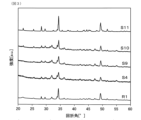
- FIG. 1 is an explanatory diagram showing the X-ray diffraction patterns of solid electrolytes S2 to S4 and solid electrolytes R1 to R3 in Example 1.
- FIG. 2 is an explanatory diagram showing the X-ray diffraction patterns of solid electrolytes S2, S6 to S8 and solid electrolyte R1 in Example 1.
- FIG. 3 is an explanatory diagram showing the X-ray diffraction patterns of solid electrolytes S4, S9 to S11 and solid electrolyte R1 in Example 1.
- FIG. 4 is a sectional view showing the main parts of the pressure forming jig used in Example 1.
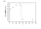
- FIG. 5 is an explanatory diagram showing the relationship between the value of x and ionic conductivity in solid electrolytes S1 to S5 and solid electrolytes R1 to R3.
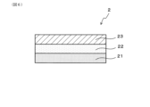
- FIG. 6 is a sectional view showing main parts of a secondary battery in Example 2.
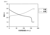
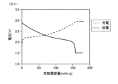
- FIG. 7 is an explanatory diagram showing the charge/discharge curve of the test cell C1 in Example 2.
- FIG. 8 is an explanatory diagram showing a charge/discharge curve of test cell C2 in Example 2.
- FIG. 9 is an explanatory diagram showing a charge/discharge curve of test cell C3 in Example 2.
- FIG. 10 is an explanatory diagram showing a charge/discharge curve of test cell C4 in Example 2.
- the solid electrolyte is Li 3-2x- ⁇ In 1-x Nb x L 6- ⁇ (where L is one or more halogens selected from the group consisting of F, Cl, Br, and I, and x is 0 ⁇ x ⁇ 0.35, and ⁇ satisfies 0 ⁇ 1).
- a solid electrolyte having such a composition has a crystal structure that can be assigned to space group C2/m. That is, the solid electrolyte has a composition of Li 3 InL 6 (L is one or more halogens selected from the group consisting of F, Cl, Br, and I, and ⁇ satisfies 0 ⁇ 1). It has a crystal structure similar to that of a solid electrolyte, and a part of In (indium) in the crystal structure of Li 3 InL 6 is replaced with Nb (niobium).
- the solid electrolyte can improve lithium ion conductivity by partially replacing In in the crystal structure with Nb. Further, even when the solid electrolyte having the above-described composition and crystal structure reacts with moisture, lithium ion conductivity can be easily restored by heating the solid electrolyte in an inert gas atmosphere. From the viewpoint of further improving the lithium ion conductivity of the solid electrolyte, the value of x in the composition formula is preferably 0.07 ⁇ x ⁇ 0.35, and 0.15 ⁇ x ⁇ 0.35. is more preferable, and it is particularly preferable that 0.20 ⁇ x ⁇ 0.35.
- the solid electrolyte contains one or more halogens L selected from the group consisting of F (fluorine), Cl (chlorine), Br (bromine), and I (iodine).
- the solid electrolyte may contain at least Cl as the halogen L.
- the solid electrolyte essentially contains Cl as the halogen L, and also contains at least one halogen among Br and I.
- the value of ⁇ in the above compositional formula is 0 or more and less than 1.
- the solid electrolyte can have a desired crystal structure. If the value of ⁇ in the compositional formula is 1 or more, it may be difficult to maintain a desired crystal structure. As a result, there is a risk that lithium ion conductivity will decrease.
- the value of ⁇ in the composition formula is preferably 0.95 or less, more preferably 0.90 or less.
- the method for manufacturing the solid electrolyte is, for example, as follows. First, halogenated Li, halogenated In, and halogenated Nb are prepared as raw materials, and these halides are weighed so as to have a desired composition ratio of the solid electrolyte. Next, using a planetary ball mill or the like, these raw material compounds are mixed while impacting them in an inert gas atmosphere. The raw material compounds mixed while being given mechanical energy in this manner become the solid electrolyte through a mechanochemical reaction.
- the solid electrolyte can also be obtained by a sintering method.
- halogenated Li, halogenated In, and halogenated Nb are prepared as raw materials, and these halides are weighed so as to have a desired composition ratio of the solid electrolyte. After mixing the raw material compounds, the mixture may be sintered in vacuum or in an inert gas atmosphere.
- the secondary battery including the solid electrolyte has a positive electrode layer containing a positive electrode active material, a negative electrode layer containing a negative electrode active material, and a separator layer interposed between the positive electrode layer and the negative electrode layer.
- the solid electrolyte may be included in any of the positive electrode layer, negative electrode layer, and separator layer.
- the solid electrolyte may be contained only in the separator layer, or may be contained in all of the positive electrode layer, negative electrode layer, and separator layer. From the viewpoint of utilizing the above-mentioned advantage of recovery of lithium ion conductivity by heating, it is preferable that the solid electrolyte is contained in all of the positive electrode layer, negative electrode layer, and separator layer.
- the specific solid electrolyte and a solid electrolyte other than the solid electrolyte may be used together.
- a solid electrolyte other than the solid electrolyte described above a sulfide solid electrolyte, an oxide solid electrolyte, an organic polymer solid electrolyte, etc. can be used.
- the sulfide solid electrolyte include Li 2 SP 2 S 5 , Li 2 S-SiS 2 , Li 10 GeP 2 S 12 , and the like.
- oxide solid electrolyte examples include garnet type solid electrolytes such as Li 7 LaZr 2 O 12 , perovskite type solid electrolytes such as (LaLi)TiO 3 , Li 3 PO 4 and its N-substituted product.
- organic polymer solid electrolyte examples include compounds of polymer compounds and lithium salts such as LiPF 6 and LiBF 6 .
- the positive electrode layer of the secondary battery contains at least a positive electrode active material.
- the positive electrode active material for example, compounds known as positive electrode active materials for lithium ion secondary batteries can be used. Examples of such compounds include oxides having a layered rock salt structure, such as lithium cobalt oxide (LCO), lithium nickel oxide (LNO), lithium nickel cobalt manganate (NCM), and lithium nickel cobalt aluminate (NCA). Examples include: oxides having a spinel structure such as lithium manganate (LMO); and phosphoric acid compounds having an olivine structure such as lithium iron phosphate.
- the content of the positive electrode active material in the positive electrode layer is preferably 60 to 99% by mass, more preferably 70 to 95% by mass.
- the positive electrode layer of the secondary battery may contain the solid electrolyte in addition to the positive electrode active material.
- the content of the solid electrolyte in the positive electrode layer is preferably 1 to 40% by mass, more preferably 5 to 30% by mass.
- the positive electrode layer may contain a binder interposed between the particles that constitute the positive electrode layer.
- the binder include fluorine-based binders such as polyvinylidene fluoride and polytetrafluoroethylene, rubber-based binders such as styrene-butadiene rubber, olefin-based binders such as polypropylene and polyethylene, and carboxymethyl cellulose. Examples include cellulose binders.
- the positive electrode layer may contain a conductive agent or a conductive aid to improve electrical conductivity.
- a conductive agent for example, graphite, carbon black, acetylene black, coke, etc. can be used.
- the content of the conductive agent and conductive aid in the positive electrode layer can be appropriately set depending on the electrical conductivity, the lithium ion conductivity of the positive electrode layer, and the desired energy density of the secondary battery.
- the negative electrode layer of the secondary battery contains at least a negative electrode active material.
- the negative electrode active material for example, compounds known as negative electrode active materials for lithium ion secondary batteries can be used. Examples of such compounds include silicon-based active materials such as Si, Si alloys and silicon oxide, metals that can react with lithium such as Sn, Sn alloys, Al and Al alloys, oxides such as SnO2 , graphite, etc. Examples include carbon materials having a graphite structure such as hard carbon, lithium-based oxides such as lithium titanate (Li 4 Ti 5 O 12 ), metallic lithium, and lithium alloys.
- the content of the negative electrode active material in the negative electrode layer is preferably 60 to 99% by mass, more preferably 70 to 95% by mass.
- the negative electrode layer of the secondary battery may contain the solid electrolyte in addition to the negative electrode active material.
- the content of the solid electrolyte in the negative electrode layer is preferably 1 to 40% by mass, more preferably 5 to 30% by mass.
- the negative electrode layer may contain a binder interposed between particles constituting the negative electrode layer, a conductive agent, and a conductive aid for increasing electrical conductivity.
- the binder, conductive agent, and conductive aid that can be used in the negative electrode layer are the same as those for the positive electrode layer.
- the separator layer of the secondary battery may contain the solid electrolyte. Further, in addition to the solid electrolyte, the separator layer may contain a binder that binds particles of the solid electrolyte to each other as necessary.
- the binder that can be used for the separator layer is the same as for the positive electrode layer.
- a method for manufacturing a secondary battery using the solid electrolyte is, for example, as follows. First, a positive electrode composite material that will become a positive electrode layer, a separator composite material that will become a separator layer, and a negative electrode composite material that will become a negative electrode layer are prepared. Next, the positive electrode mixture is placed into the press mold. Thereafter, by compressing the positive electrode mixture in the press mold, a positive electrode layer is formed in the press mold.
- a separator mixture is placed on the positive electrode layer in the press mold, and the separator mixture is compressed together with the positive electrode layer. Thereby, a separator layer is formed on the positive electrode layer. Thereafter, the negative electrode composite material is placed on the separator layer in the press mold, and the negative electrode composite material is compressed together with the positive electrode layer and the separator layer.
- the order of forming the positive electrode layer, negative electrode layer, and separator layer can be changed as appropriate. Further, in the above-described method, it is also possible to stack a plurality of single cells by repeatedly forming a positive electrode layer, a separator layer, and a negative electrode layer.
- a secondary battery After forming a single cell as described above, a secondary battery can be obtained by encapsulating the single cell in an exterior material equipped with a terminal for extracting power to the outside.
- the method for manufacturing a secondary battery described above it is preferable to produce a single cell having the positive electrode layer, the negative electrode layer, and the separator layer, and then heat the single cell in an inert gas atmosphere. .
- the lithium ion conductivity of the solid electrolyte can be restored by heating the single cell in an inert gas atmosphere even if moisture is contained in the atmosphere before the single cell is manufactured. I can do it.
- restoring the lithium ion conductivity of the solid electrolyte by heating and then encapsulating the single cell in the exterior material, a secondary battery with excellent characteristics can be easily obtained.
- the moisture in the atmosphere is controlled from heating the single cell to enclosing the single cell in the exterior material, the moisture in the solid electrolyte lithium can be removed in the final secondary battery.
- the effect on ionic conductivity can be reduced. Therefore, there is no need to strictly control the amount of moisture in the atmosphere during each process from the production of each composite material to the formation of a single cell, making it easy to avoid increases in manufacturing costs and environmental impact during manufacturing. can do.
- the heating temperature and heating time of the single cell may be appropriately set depending on the composition of the solid electrolyte, etc. However, if the heating temperature of the single cell is too low or the heating time of the single cell is too short, there is a risk that the recovery of the lithium ion conductivity of the solid electrolyte will be insufficient. On the other hand, if the heating temperature of a single cell is excessively high or the heating temperature of a single cell is excessively long, each substance contained in the single cell may change in quality and the characteristics of the secondary battery may deteriorate. .
- Example 1 In this example, an example of the solid electrolyte will be described with reference to FIGS. 1 to 5.
- the solid electrolytes of this example (Table 1, solid electrolytes S1 to S14) are Li 3-2x- ⁇ In 1-x Nb x L 6- ⁇ (L is selected from the group consisting of F, Cl, Br, and I). x satisfies 0 ⁇ x ⁇ 0.35, and ⁇ satisfies 0 ⁇ 1).
- the method for manufacturing the solid electrolyte of this example is as follows. In producing the solid electrolyte, all operations were performed in an argon atmosphere with a dew point of -70° C. or lower and an oxygen concentration of 1 volume ppm or lower. First, InCl 3 , NbCl 5 , LiF, LiCl, LiBr, and LiI as raw material compounds were weighed so as to have a desired molar ratio. These raw material compounds were encapsulated together with ceramic balls in a zirconia pod, and then the zirconia pod was encapsulated in a closed container. Thereafter, the sealed container was attached to a planetary ball mill and rotated at a rotation speed of 500 rpm for 30 hours. Through this operation, the raw material compounds in the zirconia pod were reacted by a mechanochemical method.
- solid electrolytes R1 to R8 having the compositions shown in Table 1 were prepared for comparison with solid electrolytes S1 to S14.
- the method for producing the solid electrolytes R1 to R5 is the same as the method for producing the solid electrolytes S1 to S14 except that the mixing ratio of the raw material compounds is different.
- the solid electrolyte R6 is Li 3 PS 4 , which is common as a sulfide solid electrolyte.
- Solid electrolyte R7 and solid electrolyte R8 each have the composition shown in Table 1. The manufacturing method of solid electrolyte R7 and solid electrolyte R8 was based on the method described in Patent Document 1.
- the crystal structure of the solid electrolyte shown in Table 1 was evaluated, the ionic conductivity was measured, and the recoverability of the ionic conductivity after exposure to the atmosphere was evaluated using the following methods.
- FIGS. 1 to 3 show X-ray diffraction patterns of solid electrolytes S2 to S4, S6 to S11, and R1 to R3 as examples.
- the vertical axis in FIGS. 1 to 3 is the diffraction intensity (relative intensity), and the horizontal axis is the diffraction angle 2 ⁇ (unit: degree).
- the pressure forming jig 1 includes a cylindrical form part 11 having a through hole 111, an upper punch 12 inserted into one end of the through hole 111 of the form part 11, and a through hole 111.
- the lower punch 13 is inserted into the other end of the hole 111.
- the frame portion 11 is made of electrically insulating ceramic.
- the upper punch 12 and the lower punch 13 are each made of electrically conductive stainless steel.
- a pellet P can be formed by sandwiching a solid electrolyte between an upper punch 12 and a lower punch 13 and compressing the solid electrolyte.
- the method for producing pellets P is as follows. First, the pressure molding jig 1 was placed in an argon atmosphere with a dew point of -70° C. or less and an oxygen concentration of 1 volume ppm or less, and the lower punch 13 was inserted into the through hole 111 of the mold part 11. In this state, the solid electrolyte stored in the argon atmosphere described above was put into the through hole 111. Thereafter, the upper punch 12 was inserted into the through hole 111, and the solid electrolyte was sandwiched between the upper punch 12 and the lower punch 13. Then, a pressure of 6000 kg/cm 2 was applied between the upper punch 12 and the lower punch 13 to compress the solid electrolyte, thereby forming solid electrolyte pellets P.
- the electrochemical AC impedance of the solid electrolyte was measured while maintaining the argon atmosphere described above. Specifically, first, while holding the pellet P by applying a pressure of 4000 kg/cm 2 between the upper punch 12 and the lower punch 13, a potentiostat equipped with a frequency response analyzer is inserted between the upper punch 12 and the lower punch 13. It was electrically connected to the pellet P via the side punch 13. Then, electrochemical AC impedance measurement was performed to measure the complex impedance of the solid electrolyte at room temperature.
- the complex impedance thus obtained was analyzed using a Cole-Cole plot, and the magnitude of the real part of the complex impedance at the measurement point where the absolute value of the phase was the smallest was defined as the resistance value R for ion conduction of the solid electrolyte.
- the ionic conductivity ⁇ (unit: mS/cm) of the solid electrolyte is determined by the above-mentioned resistance value R (unit: ⁇ ), the cross-sectional area S (unit: cm 2 ) of the pellet P, and the thickness L (unit: cm) and is expressed by the following equation (1).
- ⁇ 1000L/(R ⁇ S)...(1)
- the cross-sectional area S of the pellet P is specifically the area of the pellet P in a plane perpendicular to the compression direction, and the thickness of the pellet P is the outer dimension of the pellet P in the compression direction.
- the ionic conductivity of each solid electrolyte was as shown in Table 1.
- the solid electrolyte exposed to the atmosphere was heated at a temperature of 300° C. for 3 hours in an argon atmosphere.
- electrochemical alternating current impedance measurement was performed in the same manner as the ionic conductivity measurement described above. Then, ionic conductivity was calculated based on the obtained complex impedance.
- Table 1 shows the ionic conductivity of each solid electrolyte after heating. Note that the symbol "-" is written in Table 1 for solid electrolytes for which recovery of ionic conductivity after exposure to the atmosphere and after heating was not evaluated.
- solid electrolytes S1 to S14 all have the above-mentioned specific composition. Further, as shown in FIGS. 1 to 3, the crystal structure of these solid electrolytes is similar to that of solid electrolyte R1 having a composition of Li 3 InCl 6 . Therefore, these solid electrolytes have higher ionic conductivity than solid electrolytes R1 to R5 whose compositions are outside the specific range.
- the value of x in the composition formula is plotted on the horizontal axis and the value of x in the composition formula is plotted on the vertical axis for solid electrolytes S1 to S5 and solid electrolytes R1 to R3 in which the value of ⁇ in the composition formula is 0 and the halogen is only Cl.
- a graph showing the values of ionic conductivity (unit: mS/cm) is shown.
- the value of x in the composition formula is greater than 0 and less than or equal to 0.35, preferably greater than or equal to 0.07 and less than or equal to 0.35, and more preferably 0.15. It can be understood that the ionic conductivity of the solid electrolyte is improved by setting it to 0.35 or more, more preferably 0.20 or more and 0.35 or less.
- the secondary battery 2 of this example includes a positive electrode layer 21 containing a positive electrode active material and a solid electrolyte, a separator layer 22 containing a solid electrolyte and laminated on the positive electrode layer 21, a negative electrode active material and It has a negative electrode layer 23 containing a solid electrolyte and laminated on a separator layer 22.
- secondary batteries 2 test cells C1 to C4 were manufactured as follows, and their charge and discharge characteristics were evaluated.
- the positive electrode active material used in the positive electrode mixture of test cell C1 was nickel cobalt lithium manganate (LiNi 1/3 Co 1/3 Mn 1/3 O 2 ), the conductive agent was carbon nanofiber, and the solid electrolyte is the solid electrolyte S4 (Li 2.4 In 0.7 Nb 0.3 Cl 6 ) in Example 1.
- the content of the conductive support agent in the positive electrode composite material is 5% by mass with respect to the total of 100% by mass of the positive electrode active material and solid electrolyte.
- the negative electrode composite material includes a negative electrode active material, a conductive aid, and a solid electrolyte.
- the negative electrode active material used in the negative electrode mixture of test cell C1 was Li 4 Ti 5 O 12
- the conductive agent was acetylene black
- the solid electrolyte was Li 3 PS 4 .
- the content of the conductive support agent in the negative electrode composite material is 5% by mass with respect to the total of 100% by mass of the negative electrode active material and solid electrolyte.
- the lower punch 13 was inserted into the through hole 111 of the mold part 11 in the pressure molding jig 1 shown in FIG.
- 50 mg of Li 3 PS 4 as a solid electrolyte was introduced into the through hole 111 .
- the upper punch 12 was inserted into the through hole 111, and a load of 1000 kg/cm 2 was applied between the upper punch 12 and the lower punch 13. Thereby, the solid electrolyte was compressed to form the separator layer 22.
- the upper punch 12 was removed from the pressure molding jig 1, and 75 mg of negative electrode mixture was put into the through hole 111. Then, the upper punch 12 was reinserted into the through hole 111, and a load of 1000 kg/cm 2 was applied between the upper punch 12 and the lower punch 13. Thereby, the negative electrode composite material was compressed to form the negative electrode layer 23 on one side of the separator layer 22.
- the lower punch 13 was removed from the pressure molding jig 1, and 20 mg of positive electrode mixture was put into the through hole 111. Then, the lower punch 13 was inserted again into the through hole 111, and a load of 4000 kg/cm 2 was applied between the upper punch 12 and the lower punch 13. Thereby, the positive electrode mixture was compressed to form the positive electrode layer 21 on the other surface of the separator layer 22. Through the above steps, a test cell C1 as a secondary battery 2 was obtained.
- test cell C2 As the solid electrolyte of the positive electrode layer in test cell C2, solid electrolyte S4, which was exposed to the atmosphere and then heated in an argon atmosphere, was used. Note that the conditions for exposing the solid electrolyte S4 to the atmosphere and the heating conditions in an argon atmosphere are the same as those in Example 1 described above. The other configuration and manufacturing method of the test cell C2 are the same as those of the test cell C1.
- Test cell C3 As the solid electrolyte of the positive electrode layer in test cell C3, solid electrolyte R6 (Li 3 PS 4 ) in Example 1 was used. The other configuration and manufacturing method of test cell C3 are the same as those of test cell C1.
- Test cell C4 As the solid electrolyte for the positive electrode layer in test cell C4, Li 3 PS 4 , which was exposed to the atmosphere and then heated in an argon atmosphere, was used. Note that the conditions for exposing Li 3 PS 4 to the atmosphere and heating conditions in an argon atmosphere are the same as those in Example 1 described above. The other configuration and manufacturing method of test cell C4 are the same as those of test cell C1.
- test cells C1 to C4 were measured by the following method.
- the test cell was charged in constant current-constant voltage mode at a temperature of 25°C.
- the current density in constant current mode was 1/10C, and when the voltage of the secondary battery reached 2.95V, switching to constant voltage mode was performed.
- the charging voltage was set to 2.95V, and charging was performed until the current density reached 1/100C.
- the current density in constant voltage mode reached 1/100C
- charging and discharging were stopped for 10 minutes to stabilize the potential of the test cell. Thereafter, the battery was discharged to 1.5V at a constant current with a current density of 1/10C.
- C which is the unit of current density during discharging, theoretically means a current density at which the charging rate becomes 100% in one hour. That is, by discharging at a current density of 1 C for 1 hour, the secondary battery can theoretically be completely discharged.
- the current density corresponding to 1C is specifically 170 mA/g.
- Figures 7 to 10 show the charge/discharge curves of each test cell.
- Table 2 also shows the discharge capacities of test cells C1 to C4 calculated based on the charge and discharge curves.
- the charge/discharge curve of test cell C2 using solid electrolyte S4 after being exposed to the atmosphere and heating is the same as that of test cell C1 using solid electrolyte S4 before being exposed to the atmosphere. There was almost no change in the charge/discharge curve. Further, as shown in Table 2, the discharge capacity of test cell C2 was about 91% of the discharge capacity of test cell C1 using solid electrolyte S4 before reacting with moisture. From these results, in a secondary battery using a solid electrolyte with the above-mentioned specific composition and crystal structure, even if the solid electrolyte reacts with moisture during the manufacturing process, heating can reduce the effects of moisture. It can be understood that it is possible to reduce this and restore the charge/discharge characteristics.
- test cell C3 using solid electrolyte R6 before being exposed to the atmosphere has approximately the same discharge capacity as test cell C1 and test cell C2.
- the discharge capacity of test cell C4 using solid electrolyte R6 decreased to about 44% of test cell C3.
- the slope of the charge/discharge curve in test cell C4 was larger than the slope of the charge/discharge curve in test cell C3, and the internal resistance during charging and discharging was increased.
- the positive electrode layer in the secondary battery contains the solid electrolyte.
- solid electrolyte may also be included in the negative electrode layer or in the separator layer. It may be If the solid electrolyte is included in one or more of the positive electrode layer, negative electrode layer, and separator layer, the above-described effects can be obtained.
Landscapes
- Chemical & Material Sciences (AREA)
- Engineering & Computer Science (AREA)
- Electrochemistry (AREA)
- General Chemical & Material Sciences (AREA)
- Organic Chemistry (AREA)
- Chemical Kinetics & Catalysis (AREA)
- Inorganic Chemistry (AREA)
- Manufacturing & Machinery (AREA)
- Materials Engineering (AREA)
- Physics & Mathematics (AREA)
- Condensed Matter Physics & Semiconductors (AREA)
- General Physics & Mathematics (AREA)
- Secondary Cells (AREA)
- Battery Electrode And Active Subsutance (AREA)
- Conductive Materials (AREA)
Abstract
固体活物質は、Li3-2x-αIn1-xNbxL6-α(ただし、LはF、Cl、Br及びIからなる群より選択される1種以上のハロゲンであり、xは0<x≦0.35を満たし、αは0≦α<1を満たす)の組成式で表される組成を有している。二次電池は、正極活物質を含む正極層と、負極活物質を含む負極層と、正極層と負極層との間に介在するセパレータ層と、を有し、正極層、負極層及びセパレータ層のうち少なくとも1つの層に前記特定の組成を有する固体電解質が含まれている。
Description
本発明は、固体電解質、二次電池及びその製造方法に関する。
リチウムイオン二次電池は、小型、軽量でありながら高い起電力を有する、エネルギー密度が高いなどの優れた特性を有している。これらの優れた特性を活かし、携帯電話及びラップトップコンピュータ等の小型電子機器や、電気自動車及びハイブリッド自動車等の大型電気駆動装置等の幅広い用途にリチウムイオン二次電池が用いられている。
近年では、二次電池の安全性をより高めることを目的として、リチウムイオン伝導性を有する固体を電解質として用いた二次電池が注目を浴びつつある。このような二次電池の中でも、二次電池を構成する材料が全て固体である二次電池は、全固体二次電池と呼ばれることもある。
二次電池に用いられる固体電解質としては、硫黄を含む化合物からなる硫化物固体電解質が知られている。硫化物固体電解質は、リチウムイオン伝導度が高い、可塑性が高いため活物質等との接触面積を広くしやすい等の固体電解質として好適な特性を有する一方、水分と容易に反応して硫化水素ガスを発生させるという問題がある。
かかる問題に対し、水分と反応した場合においても硫化水素ガスが発生することのない、ハロゲン化物固体電解質が提案されている。例えば特許文献1には、Li、M、及びXを含み、Mはイットリウムを少なくとも含み、XはCl、Br、およびIからなる群より選ばれる少なくとも1種である固体電解質が記載されている。
しかし、特許文献1に記載の固体電解質は、水分との反応によってリチウムイオン伝導性が著しく低下するという問題がある。そのため、特許文献1に記載の固体電解質を用いて二次電池を製造する場合には、製造過程における雰囲気中の水分や、外装材による封止状態等を厳密に管理する必要があり、製造コストの上昇や、製造時の環境負荷の増大を招いている。また、二次電池の特性を向上させる観点から、特許文献1に記載の固体電解質よりもさらにイオン伝導性を向上させることが望まれている。
本発明は、かかる背景に鑑みてなされたものであり、高いリチウムイオン伝導性を有するとともに、水分との反応後にリチウムイオン伝導性を容易に回復することができる固体電解質、この固体電解質を用いた二次電池及びその製造方法を提供しようとするものである。
本発明の一態様は、Li3-2x-αIn1-xNbxL6-α(ただし、LはF、Cl、Br及びIからなる群より選択される1種以上のハロゲンであり、xは0<x≦0.35を満たし、αは0≦α<1を満たす)の組成式で表される組成を有する、固体電解質にある。
本発明の他の態様は、正極活物質を含む正極層と、
負極活物質を含む負極層と、
前記正極層と前記負極層との間に介在するセパレータ層と、を有し、
前記正極層、前記負極層及び前記セパレータ層のうち少なくとも1つの層に前記の態様の固体電解質が含まれている、二次電池にある。
負極活物質を含む負極層と、
前記正極層と前記負極層との間に介在するセパレータ層と、を有し、
前記正極層、前記負極層及び前記セパレータ層のうち少なくとも1つの層に前記の態様の固体電解質が含まれている、二次電池にある。
本発明のさらに他の態様は、前記の態様の二次電池の製造方法であって、
前記正極層と、前記負極層と、前記セパレータ層とを有する単セルを作製し、
その後、前記単セルを不活性ガス雰囲気中で加熱する、二次電池の製造方法にある。
前記正極層と、前記負極層と、前記セパレータ層とを有する単セルを作製し、
その後、前記単セルを不活性ガス雰囲気中で加熱する、二次電池の製造方法にある。
前記固体電解質は、前記特定の組成を有している。かかる組成を有する固体電解質は、高いリチウムイオン伝導性を有している。また、前記固体電解質は、硫黄原子を含まないため、水分と反応した場合においても硫化水素などの有害なガスが発生することはない。さらに、前記固体電解質は、一旦水分と反応した場合であっても、不活性ガス雰囲気中で加熱することによってリチウムイオン伝導性を容易に回復することができる。
また、前記二次電池は、正極層、負極層及びセパレータ層のうち少なくとも1つの層に前記の態様の固体電解質が含まれている。そのため、例えば二次電池の製造過程での大気との暴露や、リークによる外装材内への大気の進入等によって水分と反応した場合においても、熱を加えることによって固体電解質のリチウムイオン伝導性を容易に回復させ、ひいては電池特性を回復させることができる。
また、前記二次電池の製造方法においては、前記固体電解質を含む単セルを作製した後、単セルを不活性ガス雰囲気中で加熱するという単純な方法により、固体電解質のリチウムイオン伝導性を回復させることができる。また、前記製造方法では、二次電池の製造途中において雰囲気中の水分等を厳密に管理しなくても、二次電池の製造の最終段階において単セルを加熱することにより電池特性を容易に回復させることができる。従って、前記製造方法によれば、製造コストの上昇や製造時の環境負荷の増大を容易に回避することができる。
以上のように、前記の態様によれば、高いリチウムイオン伝導性を有するとともに、水分との反応後にリチウムイオン伝導性を回復することができる固体電解質、この固体電解質を用いた二次電池及びその製造方法を提供することができる。
(固体電解質)
前記固体電解質は、Li3-2x-αIn1-xNbxL6-α(ただし、LはF、Cl、Br及びIからなる群より選択される1種以上のハロゲンであり、xは0<x≦0.35を満たし、αは0≦α<1を満たす)の組成式で表される組成を有している。
前記固体電解質は、Li3-2x-αIn1-xNbxL6-α(ただし、LはF、Cl、Br及びIからなる群より選択される1種以上のハロゲンであり、xは0<x≦0.35を満たし、αは0≦α<1を満たす)の組成式で表される組成を有している。
前記組成式におけるxの値、つまり、Li、In、Nb及びハロゲンの含有率の合計に対するNbの含有率のモル比は0を超え0.35以下である。かかる組成を有する固体電解質は、空間群C2/mに帰属可能な結晶構造を有している。すなわち、前記固体電解質は、Li3InL6(ただし、LはF、Cl、Br及びIからなる群より選択される1種以上のハロゲンであり、αは0≦α<1を満たす)の組成を有する固体電解質と同様の結晶構造を有しており、Li3InL6の結晶構造におけるIn(インジウム)の一部がNb(ニオブ)に置換されている。
前記固体電解質は、結晶構造中のInの一部がNbに置換されていることにより、リチウムイオン伝導性を向上させることができる。また、前述した組成及び結晶構造を有する固体電解質は、水分と反応した場合においても、不活性ガス雰囲気中で固体電解質を加熱することによってリチウムイオン伝導性を容易に回復することができる。固体電解質のリチウムイオン伝導性をより向上させる観点からは、前記組成式におけるxの値は0.07≦x≦0.35であることが好ましく、0.15≦x≦0.35であることがより好ましく、0.20≦x≦0.35であることが特に好ましい。
前記組成式におけるxの値が0.35よりも大きい場合には、Inの置換量が過度に多くなり、所望の結晶構造を維持することが難しくなるおそれがある。その結果、リチウムイオン伝導性の低下を招くおそれがある。
前記固体電解質には、F(フッ素)、Cl(塩素)、Br(臭素)及びI(ヨウ素)からなる群より選択される1種以上のハロゲンLが含まれている。例えば、前記固体電解質には、ハロゲンLとして、少なくともClが含まれていてもよい。固体電解質のリチウムイオン伝導性をより高める観点からは、前記固体電解質は、ハロゲンLとしてClを必須に含むとともに、Br及びIのうち少なくとも一方のハロゲンを含んでいることがより好ましい。
前記組成式におけるαの値は0以上1未満である。前記組成式におけるαの値を前記特定の範囲とすることにより、固体電解質の結晶構造を所望の構造とすることができる。前記組成式におけるαの値が1以上の場合には、所望の結晶構造を維持することが難しくなるおそれがある。その結果、リチウムイオン伝導性の低下を招くおそれがある。所望の結晶構造を備えた固体電解質をより確実に得る観点から、前記組成式におけるαの値は0.95以下であることが好ましく、0.90以下であることがより好ましい。
(固体電解質の製造方法)
前記固体電解質の製造方法は、例えば以下の通りである。まず、原料としてハロゲン化Li、ハロゲン化In及びハロゲン化Nbを準備し、これらのハロゲン化物を所望の固体電解質の組成比となるように秤量する。次に、遊星型ボールミル等を用い、不活性ガス雰囲気中においてこれらの原料化合物に衝撃を与えながら混合する。このように機械的エネルギーを与えられながら混合された原料化合物は、メカノケミカル反応によって前記固体電解質となる。
前記固体電解質の製造方法は、例えば以下の通りである。まず、原料としてハロゲン化Li、ハロゲン化In及びハロゲン化Nbを準備し、これらのハロゲン化物を所望の固体電解質の組成比となるように秤量する。次に、遊星型ボールミル等を用い、不活性ガス雰囲気中においてこれらの原料化合物に衝撃を与えながら混合する。このように機械的エネルギーを与えられながら混合された原料化合物は、メカノケミカル反応によって前記固体電解質となる。
また、上記のメカノケミカル法に替えて、焼結法により前記固体電解質を得ることもできる。この場合、原料としてハロゲン化Li、ハロゲン化In及びハロゲン化Nbを準備し、これらのハロゲン化物を所望の固体電解質の組成比となるように秤量する。そして、原料化合物を混合した後、真空中または不活性ガス雰囲気中において混合物を焼結させればよい。
以上の方法により得られた固体電解質を保存する場合、保存時における雰囲気中の水分量の厳密な管理は不要である。前述したように、硫化物固体電解質においては、水分との反応によるリチウムイオン伝導性の低下を回避する観点から、保存時における雰囲気中の水分量を厳密に管理する必要がある。これに対し、前記固体電解質は、水分と反応した場合であっても固体電解質を加熱することによって水分の影響を軽減し、リチウムイオン伝導性を回復させることができる。それ故、例えば大気などの水分を含む雰囲気中で固体電解質を保存した場合であっても、二次電池の組み立てが完了するまでの間に前記固体電解質を加熱することにより、固体電解質のリチウムイオン伝導性を回復させることができる。その結果、高いリチウムイオン伝導性を有する固体電解質を備えた二次電池を得ることができる。
(二次電池)
前記固体電解質を備えた二次電池は、正極活物質を含む正極層と、負極活物質を含む負極層と、正極層と負極層との間に介在するセパレータ層とを有している。前記固体電解質は、正極層、負極層及びセパレータ層のいずれに含まれていてもよい。例えば、前記固体電解質は、セパレータ層のみに含まれていてもよいし、正極層、負極層及びセパレータ層の全てに含まれていてもよい。前述した加熱によるリチウムイオン伝導性の回復という利点を活かす観点からは、固体電解質が正極層、負極層及びセパレータ層の全てに含まれていることが好ましい。
前記固体電解質を備えた二次電池は、正極活物質を含む正極層と、負極活物質を含む負極層と、正極層と負極層との間に介在するセパレータ層とを有している。前記固体電解質は、正極層、負極層及びセパレータ層のいずれに含まれていてもよい。例えば、前記固体電解質は、セパレータ層のみに含まれていてもよいし、正極層、負極層及びセパレータ層の全てに含まれていてもよい。前述した加熱によるリチウムイオン伝導性の回復という利点を活かす観点からは、固体電解質が正極層、負極層及びセパレータ層の全てに含まれていることが好ましい。
また、前記二次電池においては、前記特定の固体電解質と、前記固体電解質以外の固体電解質とが併用されていてもよい。前記固体電解質以外の固体電解質としては、硫化物固体電解質や酸化物固体電解質、有機ポリマー固体電解質等を使用することができる。硫化物固体電解質としては、例えば、Li2S-P2S5、Li2S-SiS2、Li10GeP2S12等が挙げられる。また、酸化物固体電解質としては、例えば、Li7LaZr2O12等のガーネット型固体電解質や(LaLi)TiO3等のペロブスカイト型固体電解質、Li3PO4及びそのN置換体などが挙げられる。有機ポリマー固体電解質としては、例えば、高分子化合物とLiPF6やLiBF6等のリチウム塩との化合物などが挙げられる。
二次電池の正極層には、少なくとも正極活物質が含まれる。正極活物質としては、例えば、リチウムイオン二次電池用の正極活物質として公知の化合物を用いることができる。このような化合物としては、例えば、コバルト酸リチウム(LCO)、ニッケル酸リチウム(LNO)、ニッケルコバルトマンガン酸リチウム(NCM)、ニッケルコバルトアルミニウム酸リチウム(NCA)等の層状岩塩型構造を有する酸化物;マンガン酸リチウム(LMO)等のスピネル構造を有する酸化物;リチウムリン酸鉄などのオリビン構造を有するリン酸化合物などが挙げられる。正極層中の正極活物質の含有量を多くすることにより、二次電池のエネルギー密度をより高めることができる。かかる観点から、正極層中の正極活物質の含有量は、60~99質量%であることが好ましく、70~95質量%であることがより好ましい。
また、二次電池の正極層には、正極活物質の他に、前記固体電解質が含まれていてもよい。正極層中の固体電解質の含有量は、1~40質量%であることが好ましく、5~30質量%であることがより好ましい。
正極層には、正極層を構成する粒子の間に介在する結着剤が含まれていてもよい。結着剤としては、例えば、ポリフッ化ビニリデン、ポリテトラフルオロエチレン等のフッ素系結着剤、スチレンブタジエンゴム等のゴム系結着剤、ポリプロピレン、ポリエチレン等のオレフィン系結着剤、カルボキシメチルセルロース等のセルロース系結着剤等が挙げられる。
また、正極層には、電気伝導性を高めるための導電剤や導電助剤が含まれていてもよい。導電剤としては、例えば黒鉛、カーボンブラック、アセチレンブラック、コークス類等を用いることができる。正極層中の導電剤及び導電助剤の含有量は、電気伝導性や正極層のリチウムイオン伝導性、所望する二次電池のエネルギー密度に応じて適宜設定することができる。
二次電池の負極層には、少なくとも負極活物質が含まれる。負極活物質としては、例えば、リチウムイオン二次電池用の負極活物質として公知の化合物を用いることができる。このような化合物としては、例えば、Si、Si合金及び酸化ケイ素などのシリコン系活物質、Sn、Sn合金、Al及びAl合金などのリチウムと反応し得る金属、SnO2等の酸化物、グラファイトやハードカーボン等のグラファイト構造を有する炭素材料、チタン酸リチウム(Li4Ti5O12)等のリチウム系酸化物、金属リチウム、リチウム合金などが挙げられる。負極層中の負極活物質の含有量を多くすることにより、二次電池のエネルギー密度をより高めることができる。かかる観点から、負極層中の負極活物質の含有量は、60~99質量%であることが好ましく、70~95質量%であることがより好ましい。
また、二次電池の負極層には、負極活物質の他に、前記固体電解質が含まれていてもよい。負極層中の固体電解質の含有量は、1~40質量%であることが好ましく、5~30質量%であることがより好ましい。
負極層には、負極層を構成する粒子の間に介在する結着剤や、電気伝導性を高めるための導電剤、導電助剤が含まれていてもよい。負極層に使用し得る結着剤、導電剤及び導電助剤は、正極層と同様である。
二次電池のセパレータ層には、前記固体電解質が含まれていてもよい。また、セパレータ層には、固体電解質の他に、必要に応じて固体電解質の粒子同士を結着させる結着剤が含まれていてもよい。セパレータ層に使用し得る結着剤は、正極層と同様である。
(二次電池の製造方法)
前記固体電解質を用いた二次電池の製造方法は、例えば以下の通りである。まず、正極層となる正極合材、セパレータ層となるセパレータ合材及び負極層となる負極合材を作製する。次に、プレス型内に正極合材を投入する。その後、プレス型内の正極合材を圧縮することにより、プレス型内に正極層を形成する。
前記固体電解質を用いた二次電池の製造方法は、例えば以下の通りである。まず、正極層となる正極合材、セパレータ層となるセパレータ合材及び負極層となる負極合材を作製する。次に、プレス型内に正極合材を投入する。その後、プレス型内の正極合材を圧縮することにより、プレス型内に正極層を形成する。
次に、プレス型内の正極層上にセパレータ合材を乗せ、セパレータ合材を正極層とともに圧縮する。これにより、正極層上にセパレータ層を形成する。その後、プレス型内のセパレータ層上に負極合材を乗せ、負極合材を正極層及びセパレータ層とともに圧縮する。以上の結果、正極層、セパレータ層及び負極層が積層されてなる単セルを得ることができる。なお、上述した方法において、正極層、負極層及びセパレータ層を形成する順序は適宜入れ替えることが可能である。また、上述した方法において、正極層の形成、セパレータ層の形成及び負極層の形成を繰り返し行うことにより、単セルを複数積層させることも可能である。
以上のようにして単セルを形成した後、外部に電力を取り出すための端子を備えた外装材に単セルを封入することにより、二次電池を得ることができる。
二次電池に前記固体電解質が用いられている場合、各合材の作製から単セルの作製までの間の工程における作業中の雰囲気は特に限定されることはない。
前述した二次電池の製造方法においては、前記正極層と、前記負極層と、前記セパレータ層とを有する単セルを作製し、その後、前記単セルを不活性ガス雰囲気中で加熱することが好ましい。この場合、単セルの作製までの雰囲気中に水分が含まれていた場合であっても、単セルを不活性ガス雰囲気中で加熱することにより、前記固体電解質のリチウムイオン伝導性を回復させることができる。そして、加熱によって固体電解質のリチウムイオン伝導性を回復させた後に単セルを外装材に封入することにより、優れた特性を有する二次電池を容易に得ることができる。
また、前記製造方法においては、単セルの加熱から外装材への単セルの封入までの間の雰囲気中の水分さえ管理すれば、最終的に得られる二次電池において、水分が固体電解質のリチウムイオン伝導性に及ぼす影響を軽減することができる。そのため、各合材の作製から単セルの形成までの間の各工程における雰囲気中の水分量を厳密に管理する必要がなくなり、製造コストの上昇や、製造時の環境負荷の増大を容易に回避することができる。
単セルの加熱温度及び加熱時間は、前記固体電解質の組成等に応じて適宜設定すればよい。ただし、単セルの加熱温度が過度に低い場合、または単セルの加熱時間が過度に短い場合には、固体電解質のリチウムイオン伝導性の回復が不十分となるおそれがある。一方、単セルの加熱温度が過度に高い場合、または単セルの加熱温度が過度に長い場合には、単セル中に含まれる各物質が変質し、二次電池の特性が低下するおそれがある。
(実施例1)
本例では、図1~図5を参照しつつ前記固体電解質の実施例を説明する。本例の固体電解質(表1、固体電解質S1~S14)は、Li3-2x-αIn1-xNbxL6-α(ただし、LはF、Cl、Br及びIからなる群より選択される1種以上のハロゲンであり、xは0<x≦0.35を満たし、αは0≦α<1を満たす)の組成式で表される組成を有している。
本例では、図1~図5を参照しつつ前記固体電解質の実施例を説明する。本例の固体電解質(表1、固体電解質S1~S14)は、Li3-2x-αIn1-xNbxL6-α(ただし、LはF、Cl、Br及びIからなる群より選択される1種以上のハロゲンであり、xは0<x≦0.35を満たし、αは0≦α<1を満たす)の組成式で表される組成を有している。
本例の固体電解質の製造方法は以下の通りである。なお、固体電解質の製造に当たっては、すべての作業を露点-70℃以下、酸素濃度1体積ppm以下のアルゴン雰囲気中において行った。まず、原料化合物としてのInCl3、NbCl5、LiF、LiCl、LiBr及びLiIを所望のモル比となるように秤量した。これらの原料化合物をジルコニアポッド中にセラミックボールとともに封入した後、ジルコニアポッドを密閉容器内に封入した。その後、密閉容器を遊星型ボールミルに取り付け、回転速度500rpmで30時間回転させた。この操作により、ジルコニアポッド内の原料化合物をメカノケミカル法によって反応させた。
遊星型ボールミルによる処理が完了した後、密閉容器を開封してジルコニアポッド内の粉体を回収した。この粉体を300℃の温度に3時間保持した。以上により、表1に示す固体電解質S1~S14を得た。
なお、本例においては、固体電解質S1~S14との比較のため、表1に示す組成を有する固体電解質R1~R8を作製した。固体電解質R1~R5の製造方法は、原料化合物の混合比が異なる以外は固体電解質S1~S14の製造方法と同様である。また、固体電解質R6は、硫化物固体電解質として一般的なLi3PS4である。固体電解質R7及び固体電解質R8は、それぞれ表1に示す組成を有している。固体電解質R7及び固体電解質R8の製造方法は、特許文献1に記載の方法に準じた。
本例では、以下の方法により、表1に示す固体電解質の結晶構造の評価、イオン伝導度の測定及び大気暴露後のイオン伝導度の回復性の評価を行った。
<結晶構造の評価>
粉末X線回折により、各固体電解質の結晶構造の評価を行った。X線回折装置としては、株式会社リガク製「SmartLab(登録商標)」を使用し、照射した特性X線はCuKα線とし、X線管電圧は40kV、照射電流は20mAとした。図1~図3に、例として固体電解質S2~S4、S6~S11及びR1~R3のX線回折パターンを示す。図1~図3の縦軸は回折強度(相対強度)であり、横軸は回折角2θ(単位:°)である。
粉末X線回折により、各固体電解質の結晶構造の評価を行った。X線回折装置としては、株式会社リガク製「SmartLab(登録商標)」を使用し、照射した特性X線はCuKα線とし、X線管電圧は40kV、照射電流は20mAとした。図1~図3に、例として固体電解質S2~S4、S6~S11及びR1~R3のX線回折パターンを示す。図1~図3の縦軸は回折強度(相対強度)であり、横軸は回折角2θ(単位:°)である。
<イオン伝導度の測定>
イオン伝導度の測定に当たっては、まず、図4に示す加圧成形治具1を用いて固体電解質のペレットPを作製した。図4に示すように、加圧成形治具1は、貫通穴111を備えた筒状の型枠部11と、型枠部11の貫通穴111の一端に挿入される上側パンチ12と、貫通穴111の他端に挿入される下側パンチ13とを有している。型枠部11は電気絶縁性のセラミックから構成されている。また、上側パンチ12及び下側パンチ13は、それぞれ電気伝導性を有するステンレス鋼から構成されている。図4に示すように、上側パンチ12と下側パンチ13との間に固体電解質を挟み込み、圧縮することによりペレットPを形成することができる。
イオン伝導度の測定に当たっては、まず、図4に示す加圧成形治具1を用いて固体電解質のペレットPを作製した。図4に示すように、加圧成形治具1は、貫通穴111を備えた筒状の型枠部11と、型枠部11の貫通穴111の一端に挿入される上側パンチ12と、貫通穴111の他端に挿入される下側パンチ13とを有している。型枠部11は電気絶縁性のセラミックから構成されている。また、上側パンチ12及び下側パンチ13は、それぞれ電気伝導性を有するステンレス鋼から構成されている。図4に示すように、上側パンチ12と下側パンチ13との間に固体電解質を挟み込み、圧縮することによりペレットPを形成することができる。
ペレットPの作製方法は、より具体的には以下の通りである。まず、露点-70℃以下、酸素濃度1体積ppm以下のアルゴン雰囲気中に加圧成形治具1を配置し、型枠部11の貫通穴111に下側パンチ13を挿入した。この状態で、前述したアルゴン雰囲気中で保管した固体電解質を貫通穴111に入れた。その後、貫通穴111内に上側パンチ12を挿入し、上側パンチ12と下側パンチ13との間に固体電解質を挟み込んだ。そして、上側パンチ12と下側パンチ13との間に6000kg/cm2の圧力を加えて固体電解質を圧縮することにより、固体電解質のペレットPを形成した。
次に、前述したアルゴン雰囲気を保ったまま、固体電解質の電気化学的交流インピーダンス測定を行った。具体的には、まず、上側パンチ12と下側パンチ13との間に4000kg/cm2の圧力を加えてペレットPを保持しつつ、周波数応答アナライザを搭載したポテンショスタットを、上側パンチ12及び下側パンチ13を介してペレットPと電気的に接続した。そして、電気化学的交流インピーダンス測定を行い、室温における固体電解質の複素インピーダンスを測定した。
このようにして得られた複素インピーダンスをCole-Coleプロットにより解析し、位相の絶対値が最も小さい測定点における複素インピーダンスの実部の大きさを固体電解質のイオン伝導に対する抵抗値Rとした。固体電解質のイオン伝導度σ(単位:mS/cm)は、前述した抵抗値R(単位:Ω)と、ペレットPの断面積S(単位:cm2)と、ペレットPの厚みL(単位:cm)とを用い、以下の式(1)で表される。
σ=1000L/(R・S) ・・・(1)
σ=1000L/(R・S) ・・・(1)
なお、ペレットPの断面積Sは、具体的には圧縮方向に対して垂直な面におけるペレットPの面積であり、ペレットPの厚みは圧縮方向におけるペレットPの外寸法である。各固体電解質のイオン伝導度は、表1に示す通りであった。
<大気暴露後のイオン伝導度の回復性の評価>
固体電解質S2~S4及び固体電解質R6~R8を用いて大気暴露後のイオン伝導度の回復性の評価を行った。まず、露点-70℃以下、酸素濃度1体積ppm以下のアルゴン雰囲気中で保管された固体電解質を、温度24~25℃、相対湿度20~22%の大気中に10分間暴露し、固体電解質と大気中の水分とを反応させた。10分経過後、固体電解質を再びアルゴン雰囲気中に移動させた。
固体電解質S2~S4及び固体電解質R6~R8を用いて大気暴露後のイオン伝導度の回復性の評価を行った。まず、露点-70℃以下、酸素濃度1体積ppm以下のアルゴン雰囲気中で保管された固体電解質を、温度24~25℃、相対湿度20~22%の大気中に10分間暴露し、固体電解質と大気中の水分とを反応させた。10分経過後、固体電解質を再びアルゴン雰囲気中に移動させた。
水分と反応させた後の固体電解質を用い、前述したイオン伝導度の測定と同様にして電気化学的交流インピーダンス測定を行った。そして、得られた複素インピーダンスに基づいてイオン伝導度を算出した。表1に、各固体電解質の大気暴露後のイオン伝導度を示す。
さらに、大気暴露後の固体電解質をアルゴン雰囲気中において300℃の温度で3時間加熱した。加熱後の固体電解質を用い、前述したイオン伝導度の測定と同様にして電気化学的交流インピーダンス測定を行った。そして、得られた複素インピーダンスに基づいてイオン伝導度を算出した。表1に、加熱後の各固体電解質のイオン伝導度を示す。なお、大気暴露後及び加熱後のイオン伝導度の回復性の評価を行わなかった固体電解質については、表1に記号「-」を記載した。

表1に示したように、固体電解質S1~S14は、いずれも前記特定の組成を有している。また、図1~図3に示したように、これらの固体電解質の結晶構造は、Li3InCl6の組成を有する固体電解質R1と同様である。そのため、これらの固体電解質は、組成が前記特定の範囲から外れている固体電解質R1~R5に比べて高いイオン伝導度を有している。
図5に、前記組成式におけるαの値が0であり、ハロゲンがClのみからなる固体電解質S1~S5及び固体電解質R1~R3について、横軸に組成式におけるxの値をとり、縦軸にイオン伝導度(単位:mS/cm)の値をとったグラフを示す。図5に示すように、ハロゲンとしてClのみを有する固体電解質においては、組成式におけるxの値を0を超え0.35以下、好ましくは0.07以上0.35以下、より好ましくは0.15以上0.35以下、さらに好ましくは0.20以上0.35以下とすることにより、固体電解質のイオン伝導度が向上することが理解できる。
また、表1に示したように、前記特定の組成及び結晶構造を有する固体電解質S2~S4は、大気に暴露し、固体電解質と水分とが反応した後であっても、固体電解質を加熱することにより、イオン伝導度を回復することができた。これに対し、固体電解質R6~R8は、水分と反応させた後に加熱を行ってもイオン伝導度が回復しなかった。
(実施例2)
本例では、前記固体電解質を用いた二次電池の例を示す。本例の二次電池2は、図6に示すように、正極活物質及び固体電解質を含む正極層21と、固体電解質を含み正極層21上に積層されたセパレータ層22と、負極活物質及び固体電解質を含みセパレータ層22上に積層された負極層23とを有している。本例においては、具体的には、以下のようにして二次電池2(テストセルC1~C4)を作製し、これらの充放電特性の評価を行った。
本例では、前記固体電解質を用いた二次電池の例を示す。本例の二次電池2は、図6に示すように、正極活物質及び固体電解質を含む正極層21と、固体電解質を含み正極層21上に積層されたセパレータ層22と、負極活物質及び固体電解質を含みセパレータ層22上に積層された負極層23とを有している。本例においては、具体的には、以下のようにして二次電池2(テストセルC1~C4)を作製し、これらの充放電特性の評価を行った。
<テストセルC1>
テストセルC1の作製過程における全ての作業は露点-70℃以下、酸素濃度1体積ppmのアルゴン雰囲気中において行った。まず、正極活物質、導電助剤及び固体電解質を含む正極合材と、負極活物質、導電助剤及び固体電解質を含む負極合材とを作製した。テストセルC1の正極合材に用いた正極活物質はニッケルコバルトマンガン酸リチウム(LiNi1/3Co1/3Mn1/3O2)であり、導電助剤はカーボンナノファイバーであり、固体電解質は実施例1における固体電解質S4(Li2.4In0.7Nb0.3Cl6)である。正極合材中の正極活物質と固体電解質との比率は、質量比においてLiNi1/3Co1/3Mn1/3O2:Li2.4In0.7Nb0.3Cl6=75:25である。また、正極合材中の導電助剤の含有率は、正極活物質と固体電解質との合計100質量%に対して5質量%である。
テストセルC1の作製過程における全ての作業は露点-70℃以下、酸素濃度1体積ppmのアルゴン雰囲気中において行った。まず、正極活物質、導電助剤及び固体電解質を含む正極合材と、負極活物質、導電助剤及び固体電解質を含む負極合材とを作製した。テストセルC1の正極合材に用いた正極活物質はニッケルコバルトマンガン酸リチウム(LiNi1/3Co1/3Mn1/3O2)であり、導電助剤はカーボンナノファイバーであり、固体電解質は実施例1における固体電解質S4(Li2.4In0.7Nb0.3Cl6)である。正極合材中の正極活物質と固体電解質との比率は、質量比においてLiNi1/3Co1/3Mn1/3O2:Li2.4In0.7Nb0.3Cl6=75:25である。また、正極合材中の導電助剤の含有率は、正極活物質と固体電解質との合計100質量%に対して5質量%である。
負極合材には、負極活物質と、導電助剤と、固体電解質とが含まれている。テストセルC1の負極合材に用いた負極活物質はLi4Ti5O12であり、導電助剤はアセチレンブラックであり、固体電解質はLi3PS4である。負極合材中の負極活物質と固体電解質との比率は、質量比においてLi4Ti5O12:Li3PS4=40:60である。また、負極合材中の導電助剤の含有率は、負極活物質と固体電解質との合計100質量%に対して5質量%である。
次に、図4に示す加圧成形治具1における、型枠部11の貫通穴111に下側パンチ13を挿入した。この状態で、貫通穴111内に固体電解質としてのLi3PS4を50mg投入した。そして、貫通穴111に上側パンチ12を挿入し、上側パンチ12と下側パンチ13との間に1000kg/cm2の荷重を加えた。これにより、固体電解質を圧縮してセパレータ層22を形成した。
次に、加圧成形治具1から上側パンチ12を抜き取り、貫通穴111内に75mgの負極合材を投入した。そして、貫通穴111に上側パンチ12を再度挿入し、上側パンチ12と下側パンチ13との間に1000kg/cm2の荷重を加えた。これにより、負極合材を圧縮してセパレータ層22の一方面に負極層23を形成した。
次に、加圧成形治具1から下側パンチ13を抜き取り、貫通穴111内に20mgの正極合材を投入した。そして、貫通穴111に下側パンチ13を再度挿入し、上側パンチ12と下側パンチ13との間に4000kg/cm2の荷重を加えた。これにより、正極合材を圧縮してセパレータ層22の他方面に正極層21を形成した。以上により、二次電池2としてのテストセルC1を得た。
<テストセルC2>
テストセルC2における正極層の固体電解質としては、大気に暴露した後にアルゴン雰囲気中で加熱した固体電解質S4を使用した。なお、固体電解質S4の大気暴露の条件及びアルゴン雰囲気中での加熱条件は、前述した実施例1の条件と同様である。テストセルC2のその他の構成及び作製方法はテストセルC1と同様である。
テストセルC2における正極層の固体電解質としては、大気に暴露した後にアルゴン雰囲気中で加熱した固体電解質S4を使用した。なお、固体電解質S4の大気暴露の条件及びアルゴン雰囲気中での加熱条件は、前述した実施例1の条件と同様である。テストセルC2のその他の構成及び作製方法はテストセルC1と同様である。
<テストセルC3>
テストセルC3における正極層の固体電解質としては、実施例1における固体電解質R6(Li3PS4)を使用した。テストセルC3のその他の構成及び作製方法はテストセルC1と同様である。
テストセルC3における正極層の固体電解質としては、実施例1における固体電解質R6(Li3PS4)を使用した。テストセルC3のその他の構成及び作製方法はテストセルC1と同様である。
<テストセルC4>
テストセルC4における正極層の固体電解質としては、大気に暴露した後にアルゴン雰囲気中で加熱したLi3PS4を使用した。なお、Li3PS4の大気暴露の条件及びアルゴン雰囲気中での加熱条件は、前述した実施例1の条件と同様である。テストセルC4のその他の構成及び作製方法はテストセルC1と同様である。
テストセルC4における正極層の固体電解質としては、大気に暴露した後にアルゴン雰囲気中で加熱したLi3PS4を使用した。なお、Li3PS4の大気暴露の条件及びアルゴン雰囲気中での加熱条件は、前述した実施例1の条件と同様である。テストセルC4のその他の構成及び作製方法はテストセルC1と同様である。
次に、以下の方法によりテストセルC1~C4の放電容量の測定を行った。まず、25℃の温度において、定電流-定電圧モードでテストセルを充電した。定電流モードにおける電流密度は1/10Cとし、二次電池の電圧が2.95Vに到達した時点で定電圧モードへの切り替えを行った。定電圧モードにおいては、充電電圧を2.95Vとし、電流密度が1/100Cに到達するまで充電を行った。定電圧モードにおける電流密度が1/100Cに到達した後、10分間充放電を休止してテストセルの電位を安定させた。その後、1/10Cの電流密度の定電流で1.5Vまで放電させた。なお、放電時の電流密度の単位である「C」は、理論上、1時間で充電率が100%となる電流密度を意味する。すなわち、1Cの電流密度で1時間放電を行うことにより、理論上、二次電池を完全に放電させることができる。本例において1Cに相当する電流密度は、具体的には170mA/gである。
図7~図10に、各テストセルの充放電曲線を示す。また、表2に、充放電曲線に基づいて算出したテストセルC1~C4の放電容量を示す。
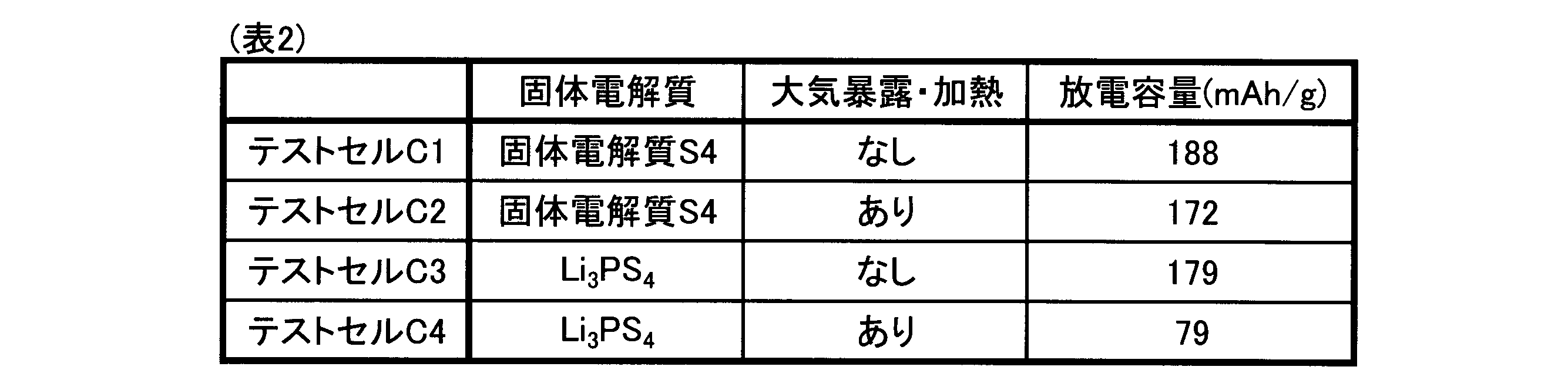
図7及び図8に示すように、大気暴露及び加熱を行った後の固体電解質S4を用いたテストセルC2の充放電曲線は、大気に暴露する前の固体電解質S4を用いたテストセルC1の充放電曲線に対してほとんど変化しなかった。また、表2に示すように、テストセルC2の放電容量は、水分と反応する前の固体電解質S4を用いたテストセルC1の放電容量の91%程度であった。これらの結果から、前記特定の組成及び結晶構造を有する固体電解質を用いた二次電池においては、その製造過程において固体電解質が水分と反応した場合であっても、加熱を行うことにより水分の影響を軽減し、充放電特性を回復可能であることが理解できる。
一方、表2に示したように、大気に暴露する前の固体電解質R6を用いたテストセルC3は、テストセルC1及びテストセルC2と概ね同程度の放電容量を有している。しかし、大気暴露及び加熱を行った後の固体電解質R6を用いたテストセルC4の放電容量は、テストセルC3の44%程度まで減少した。また、図9と図10との比較から、テストセルC4における充放電曲線の傾きはテストセルC3における充放電曲線の傾きよりも大きく、充放電時の内部抵抗が上昇していた。これらの結果から、従来の硫化物固体電解質を用いた場合、その製造過程において固体電解質が一旦水分と反応すると、その後で加熱を行っても充放電特性が回復しないことが理解できる。
以上の結果によれば、二次電池における正極層に前記固体電解質が含まれていることが好ましいことが理解できる。
以上、実施例に基づいて本発明に係る固体電解質及び二次電池の具体的な態様を説明したが、本発明に係る固体電解質及び二次電池の態様は前述した実施例の態様に限定されるものではなく、本発明の趣旨を損なわない範囲で構成を適宜変更することができる。
例えば、上述の実施例においては、正極層中に前記固体電解質が含まれている二次電池の例を示したが、前記固体電解質は、負極層に含まれていてもよく、セパレータ層に含まれていてもよい。前記固体電解質が、正極層、負極層及びセパレータ層のうち1つ以上の層に含まれていれば、前述した効果を得ることができる。
Claims (4)
- Li3-2x-αIn1-xNbxL6-α(ただし、LはF、Cl、Br及びIからなる群より選択される1種以上のハロゲンであり、xは0<x≦0.35を満たし、αは0≦α<1を満たす)の組成式で表される組成を有する、固体電解質。
- 前記固体電解質は、前記ハロゲンとして少なくともClを含む、請求項1に記載の固体電解質。
- 正極活物質を含む正極層と、
負極活物質を含む負極層と、
前記正極層と前記負極層との間に介在するセパレータ層と、を有し、
前記正極層、前記負極層及び前記セパレータ層のうち少なくとも1つの層に請求項1または2に記載の固体電解質が含まれている、二次電池。 - 請求項3に記載の二次電池の製造方法であって、
前記正極層と、前記負極層と、前記セパレータ層とを有する単セルを作製し、
その後、前記単セルを不活性ガス雰囲気中で加熱する、二次電池の製造方法。
Applications Claiming Priority (2)
| Application Number | Priority Date | Filing Date | Title |
|---|---|---|---|
| JP2022050412A JP2023143175A (ja) | 2022-03-25 | 2022-03-25 | 固体電解質、二次電池及びその製造方法 |
| JP2022-050412 | 2022-03-25 |
Publications (1)
| Publication Number | Publication Date |
|---|---|
| WO2023181704A1 true WO2023181704A1 (ja) | 2023-09-28 |
Family
ID=88101164
Family Applications (1)
| Application Number | Title | Priority Date | Filing Date |
|---|---|---|---|
| PCT/JP2023/004817 Ceased WO2023181704A1 (ja) | 2022-03-25 | 2023-02-13 | 固体電解質、二次電池及びその製造方法 |
Country Status (2)
| Country | Link |
|---|---|
| JP (1) | JP2023143175A (ja) |
| WO (1) | WO2023181704A1 (ja) |
Citations (2)
| Publication number | Priority date | Publication date | Assignee | Title |
|---|---|---|---|---|
| JP2016139461A (ja) * | 2015-01-26 | 2016-08-04 | 株式会社日立製作所 | 電気化学素子用固体電解質及びそれを用いた全固体電池 |
| WO2021089693A1 (en) * | 2019-11-07 | 2021-05-14 | Basf Se | Lithium transition metal halides |
Family Cites Families (1)
| Publication number | Priority date | Publication date | Assignee | Title |
|---|---|---|---|---|
| JP7174181B1 (ja) * | 2021-07-21 | 2022-11-17 | 住友化学株式会社 | リチウム含有塩化物及びその製造方法、並びに固体電解質及び電池 |
-
2022
- 2022-03-25 JP JP2022050412A patent/JP2023143175A/ja active Pending
-
2023
- 2023-02-13 WO PCT/JP2023/004817 patent/WO2023181704A1/ja not_active Ceased
Patent Citations (2)
| Publication number | Priority date | Publication date | Assignee | Title |
|---|---|---|---|---|
| JP2016139461A (ja) * | 2015-01-26 | 2016-08-04 | 株式会社日立製作所 | 電気化学素子用固体電解質及びそれを用いた全固体電池 |
| WO2021089693A1 (en) * | 2019-11-07 | 2021-05-14 | Basf Se | Lithium transition metal halides |
Also Published As
| Publication number | Publication date |
|---|---|
| JP2023143175A (ja) | 2023-10-06 |
Similar Documents
| Publication | Publication Date | Title |
|---|---|---|
| US10879562B2 (en) | Solid electrolyte, preparation method thereof, and all-solid-state battery employing the same | |
| JP6997216B2 (ja) | 固体電解質 | |
| CN111448619B (zh) | 固体电解质材料和电池 | |
| US12315876B2 (en) | Sulfide-based solid electrolyte particles | |
| JP6293383B1 (ja) | リチウム二次電池用硫化物系固体電解質 | |
| KR102044506B1 (ko) | 고체 전해질, 그 제조 방법 및 이를 포함하는 전고체 전지 | |
| CN110800149A (zh) | 锂二次电池的固体电解质及该固体电解质用硫化物系化合物 | |
| CN107112586A (zh) | 锂离子电池用硫化物系固体电解质和固体电解质化合物 | |
| CN115428186A (zh) | 正极材料和电池 | |
| CN115699365B (zh) | 正极活性物质、正极材料、电池和正极活性物质的制造方法 | |
| JP7196625B2 (ja) | 硫化物固体電解質粒子及びその製造方法、並びに、全固体電池 | |
| EP4317059A1 (en) | Solid electrolyte | |
| CN111279430A (zh) | 固体电解质材料及电池 | |
| JP2020173992A (ja) | 硫化物固体電解質、硫化物固体電解質の製造方法、電極体および全固体電池 | |
| CN115699366A (zh) | 正极活性物质、正极材料、电池和正极活性物质的制造方法 | |
| CN111406332A (zh) | 非水类电解质二次电池用正极活性物质、非水类电解质二次电池用正极活性物质的制造方法 | |
| JPWO2019082992A1 (ja) | ニッケル複合酸化物、リチウムニッケル複合酸化物の製造方法 | |
| KR20220158807A (ko) | 황화물계 무기 고체 전해질 재료, 고체 전해질, 고체 전해질막 및 리튬 이온 전지 | |
| WO2022215337A1 (ja) | 固体電解質材料およびそれを用いた電池 | |
| CN114503304A (zh) | 过渡金属硫化物化合物在固态蓄电池正电极中的用途 | |
| WO2023181704A1 (ja) | 固体電解質、二次電池及びその製造方法 | |
| KR20230165525A (ko) | 황화물계 고체전해질의 제조방법, 황화물계 고체전해질, 고체 전해질막 및 전고체 전지 | |
| TWI880323B (zh) | 鹵化物固體電解質、製造其之方法及包含其之二次電池 | |
| CN115699364A (zh) | 正极活性物质、正极材料、电池和正极活性物质的制造方法 | |
| WO2020175554A1 (ja) | リチウムイオン二次電池用正極活物質、リチウムイオン二次電池用正極活物質の製造方法、リチウムイオン二次電池 |
Legal Events
| Date | Code | Title | Description |
|---|---|---|---|
| 121 | Ep: the epo has been informed by wipo that ep was designated in this application |
Ref document number: 23774303 Country of ref document: EP Kind code of ref document: A1 |
|
| NENP | Non-entry into the national phase |
Ref country code: DE |
|
| 122 | Ep: pct application non-entry in european phase |
Ref document number: 23774303 Country of ref document: EP Kind code of ref document: A1 |