WO2023181474A1 - 測定プローブの保管装置および保管方法 - Google Patents
測定プローブの保管装置および保管方法 Download PDFInfo
- Publication number
- WO2023181474A1 WO2023181474A1 PCT/JP2022/040121 JP2022040121W WO2023181474A1 WO 2023181474 A1 WO2023181474 A1 WO 2023181474A1 JP 2022040121 W JP2022040121 W JP 2022040121W WO 2023181474 A1 WO2023181474 A1 WO 2023181474A1
- Authority
- WO
- WIPO (PCT)
- Prior art keywords
- air
- probe
- measurement
- storage
- measurement probe
- Prior art date
Links
- 239000000523 sample Substances 0.000 title claims abstract description 148
- 238000005259 measurement Methods 0.000 title claims abstract description 110
- 238000000034 method Methods 0.000 title claims description 22
- 230000007246 mechanism Effects 0.000 claims abstract description 28
- 238000009413 insulation Methods 0.000 claims description 2
- 230000003287 optical effect Effects 0.000 description 25
- 238000004441 surface measurement Methods 0.000 description 12
- 238000010586 diagram Methods 0.000 description 9
- 241001422033 Thestylus Species 0.000 description 7
- 210000000078 claw Anatomy 0.000 description 7
- XAGFODPZIPBFFR-UHFFFAOYSA-N aluminium Chemical compound [Al] XAGFODPZIPBFFR-UHFFFAOYSA-N 0.000 description 5
- 229910052782 aluminium Inorganic materials 0.000 description 5
- 230000008859 change Effects 0.000 description 4
- 230000007423 decrease Effects 0.000 description 3
- 239000004065 semiconductor Substances 0.000 description 3
- XEEYBQQBJWHFJM-UHFFFAOYSA-N Iron Chemical compound [Fe] XEEYBQQBJWHFJM-UHFFFAOYSA-N 0.000 description 2
- 206010037660 Pyrexia Diseases 0.000 description 2
- 239000000919 ceramic Substances 0.000 description 2
- 238000001816 cooling Methods 0.000 description 2
- 239000011810 insulating material Substances 0.000 description 2
- 238000003825 pressing Methods 0.000 description 2
- 230000008439 repair process Effects 0.000 description 2
- 230000015572 biosynthetic process Effects 0.000 description 1
- 238000005336 cracking Methods 0.000 description 1
- 230000000694 effects Effects 0.000 description 1
- 230000006870 function Effects 0.000 description 1
- 229910052742 iron Inorganic materials 0.000 description 1
- 239000000463 material Substances 0.000 description 1
- 230000000737 periodic effect Effects 0.000 description 1
- 230000008569 process Effects 0.000 description 1
- 238000003786 synthesis reaction Methods 0.000 description 1
Images


Classifications
-
- G—PHYSICS
- G01—MEASURING; TESTING
- G01B—MEASURING LENGTH, THICKNESS OR SIMILAR LINEAR DIMENSIONS; MEASURING ANGLES; MEASURING AREAS; MEASURING IRREGULARITIES OF SURFACES OR CONTOURS
- G01B21/00—Measuring arrangements or details thereof, where the measuring technique is not covered by the other groups of this subclass, unspecified or not relevant
-
- G—PHYSICS
- G01—MEASURING; TESTING
- G01B—MEASURING LENGTH, THICKNESS OR SIMILAR LINEAR DIMENSIONS; MEASURING ANGLES; MEASURING AREAS; MEASURING IRREGULARITIES OF SURFACES OR CONTOURS
- G01B5/00—Measuring arrangements characterised by the use of mechanical techniques
- G01B5/004—Measuring arrangements characterised by the use of mechanical techniques for measuring coordinates of points
- G01B5/008—Measuring arrangements characterised by the use of mechanical techniques for measuring coordinates of points using coordinate measuring machines
- G01B5/012—Contact-making feeler heads therefor
Definitions
- the present invention relates to a storage device for a contact-type shape measurement probe used in a three-dimensional shape measurement device that obtains positional information on a surface to be measured such as an optical component or a mold.
- a three-dimensional shape measuring machine is widely known as a method for measuring with high precision the shape of an aspherical surface such as an optical component or a mold.
- a three-dimensional shape measuring machine with a contact-type measurement probe moves the measurement probe along the surface of the object to be measured while keeping the tip of the measurement probe in contact with the object.
- the surface shape of the object to be measured is measured from the positional relationship with the surface.
- One such measuring device is a three-dimensional shape measuring device that uses a laser length measuring device and a reference plane mirror.
- the top surface probe and the side surface probe are installed at positions shifted in the X direction.
- the X position relative to the object to be measured is shifted on the XY stage and the measurement is performed.
- the top surface probe it is necessary to evacuate the side surface probe from the measurement area, and during measurement with the side surface probe, it is necessary to evacuate the top surface probe from the measurement area.
- the measurement sample is large in the X and Y directions, there is a problem that the apparatus becomes large and the cost becomes high.
- the cost of the entire device can be kept low, although the time and effort required to replace the probes increases.
- the air bearing type measurement probe is made replaceable, the following problems arise.
- the measurement probe is stored, compared to when it is in use when air is supplied to the air bearing, the cooling effect due to adiabatic expansion when air is released into the atmosphere at the tip does not occur.
- a temperature rise occurs and thermal expansion occurs at the tip of the probe, which causes continuous deformation of the tip during measurement, making it impossible to maintain measurement accuracy on the order of 0.1 ⁇ m.
- the present invention solves the conventional problems, and aims to provide a storage device and a storage method for maintaining measurement accuracy of a measurement probe having an air bearing.
- a storage device for storing a measurement probe used by a shape measuring device, wherein the measurement probe has an air bearing configured to allow a stylus to be moved in contact with a measurement object.
- the storage device includes a storage mechanism for storing the measurement probe, and an air pump configured to continuously supply air to the air bearing when the measurement probe is stored in the storage mechanism. A supply mechanism.
- the present invention it is possible to suppress the temperature rise of the measurement probe during storage, and it is possible to achieve highly accurate measurement.
- FIG. 1 Schematic configuration of shape measuring device according to embodiment Configuration of the Z-axis stage section in the shape measuring device shown in Figure 1 Condition of top surface measurement probe during measurement Condition of top surface measurement probe during storage
- Other examples of top surface measurement probe conditions during storage Condition of side measurement probe during measurement Condition of side measurement probe during storage are diagrams showing the procedure for replacing the top surface measurement probe.
- (a) and (b) are diagrams showing the procedure for replacing the top surface measurement probe.
- (a) and (b) are diagrams showing the procedure for replacing the top surface measurement probe.
- Diagram showing the procedure for replacing the top surface measurement probe (a) and (b) are diagrams showing the procedure for replacing the side surface measurement probe.
- (a) and (b) are diagrams showing the procedure for replacing the side surface measurement probe.
- FIG. 1 is a diagram showing a schematic configuration of a shape measuring device according to an embodiment.
- the shape measuring device 100 shown in FIG. 1 measures the three-dimensional shape of a measurement object using a top surface measurement probe (abbreviated as top surface probe when appropriate) and a side surface measurement probe (abbreviated as side surface probe as appropriate). It is a device.
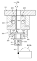
- FIG. 2 is a diagram showing the configuration of the Z-axis stage section 101.
- the shape measuring device 100 includes an XY stage (not shown), a Z-axis stage section 101, and a control section (not shown).
- the XY stage is disposed on the surface plate 110 so as to be movable in the XY axes directions, and allows the measurement unit 103a to be movable in the XY axes directions.
- the Z-axis stage section 101 is supported by a surface plate 110 so as to be movable in the Z-axis direction, that is, in the vertical direction (vertical direction), and supports the probe section 3 to be brought into contact with the measurement surface of the object at its lower end. It can be moved up and down.
- the control unit is connected to the focus optical system 4, the XY stage, the Z-axis stage unit 101, the He-Ne laser 64, and the like, and controls the three-dimensional shape measurement operation by controlling the respective operations. At this time, the control section controls the Z-axis stage section 101 so that the contact force in the Z direction by the probe section 3 is constant.
- the X-axis length measurement laser beam is irradiated onto the X-axis direction mirror 115, and the Y-axis length measurement laser light is irradiated onto the Y-axis direction mirror (not shown).
- the probe section 3 is brought into contact with the object to be measured while the measurement unit 103a is moved in the X-axis direction and the Y-axis direction by the XY stage.
- the movement of the probe section 3 is detected by an optical system connected to the Z-axis stage section 101, and the three-dimensional shape of the object to be measured is measured.
- the shape measuring device 100 uses an XY stage that moves the measurement surface of the probe section 3 in the XY direction, and a Z-axis stage section 101 that moves the probe section 3 in the Z direction. I am trying to move the position in the XYZ directions.
- the Z-axis stage unit 101 includes an air slider outer frame 1, an air slider hollow shaft 2, two support arms 5, two drive units 7, two support units 8, etc. We are prepared.
- the focus optical system 4 is an optical system that includes at least a He-Ne laser 64, and is provided on the air slider hollow shaft 2. As shown in FIG. 2, the focus optical system 4 is roughly composed of a He--Ne laser 64, a semiconductor laser optical system 50, a dichroic mirror 52, a collimator lens 53, and a mirror 54.
- the semiconductor laser optical system 50 and the dichroic mirror 52 are arranged at the upper end of the air slider hollow shaft 2.
- the collimator lens 53 and mirror 54 are arranged at the lower end of the air slider hollow shaft 2.
- the mirror 54 is fixed to the upper end of a stylus 56 supported by a micro slider 55 of the probe section 3.
- a tilting optical system 10 is provided on the air slider hollow shaft 2 so as to be installed within the space of the optical path of the focusing optical system 4.
- the tilting optical system 10 includes a semiconductor laser (not shown) for the tilting optical system and a mirror 54.
- the micro slider 55 installed in the lens barrel of the probe section 3 is tilted, the light emitted from the tilt optical system 10 is reflected by the mirror 54 on the top surface of the micro slider 55, and this change is detected and the tilt is corrected. I do.
- the air slider hollow shaft 2 is a vertically elongated rectangular parallelepiped cylindrical member, and functions as a Z-axis drive shaft of the Z-axis stage section 101.
- the air slider hollow shaft 2 has a focusing optical system 4 arranged at its upper end and a probe section 3 arranged at its lower end.
- a through hole 6 is provided in the center of the air slider hollow shaft 2, and an optical path is formed in the through hole 6 to connect the focusing optical system 4 and the mirror 54 at the upper end of the probe section 3.
- the air slider hollow shaft 2 is made of a heat insulating material such as ceramic.
- the drive unit 7 is arranged symmetrically with respect to the central axis of the air slider hollow shaft 2 at a position near the air slider hollow shaft 2 of each support arm 5.
- the drive unit 7 is capable of driving the air slider hollow shaft 2 in the axial direction with respect to the air slider outer frame 1 via the two support arms 5.
- the pair of drive parts 7 are symmetrical with respect to the central axis of the air slider hollow shaft 2.
- each drive section 7 is constituted by a linear motor 20, which is an example of an actuator.
- an air cylinder 27 is connected to the tip of each support arm 5 via an air pad 28.
- FIG. 1 As shown in FIG.
- the linear motor 20 includes a coil 21 formed in the shape of a rectangular frame and a magnet (not shown), and is driven and controlled by a control section.
- a coil 21 is arranged near the air slider hollow shaft 2 of each support arm 5, and the support arm 5 is connected to the center of the coil 21 in the axial direction.
- the coil 21 is fitted on the outside of a central yoke (not shown) and is freely movable in the vertical direction.
- a predetermined drive current is applied to the coil 21, thereby moving the air slider hollow shaft 2 in the vertical direction with respect to the fixed central yoke.
- the linear motor 20 used in this embodiment has a moving coil type in which the coil 21 is supported by the support arm 5 and the magnet is fixed to the air slider outer frame 1.
- the overall weight of the movable portion of the linear motor 20 can be reduced. Moreover, rotational moment can also be suppressed, power consumption applied to the motor can be suppressed, and thermal deformation can be suppressed.
- a mirror 54 for measuring the height in the Z direction is provided on the upper surface side of the measurement unit 103a.
- the height of the probe section 3 in the Z direction is directly measured by measuring the position of the surface of the mirror 54 using a frequency stabilized laser with a wavelength of 633 nm as a scale.
- the wavelength change rate due to temperature changes in the air of the frequency stabilized laser, so-called linear expansion coefficient is about 1/20 to 1/10 smaller than the linear expansion coefficient of aluminum, iron, etc. that constitute the mechanical part of the measurement unit 103a. . Therefore, even if the mechanical parts constituting the measurement unit 103a undergo thermal deformation due to temperature changes, measurement errors due to changes in measured values due to temperature can be kept small.
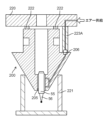
- the shape measuring device 100 includes a storage device 70 that stores measurement probes.
- the storage device 70 is simplified in FIG. 1, it includes a storage mechanism for storing the measurement probe and a mechanism for continuously supplying air to the air bearing when the measurement probe is stored in the storage mechanism. and an air supply mechanism configured. Note that, as shown in FIG. 1, the height of the tip of the stylus of the probe stored in the storage device 70 may be adjusted to the height of the tip of the stylus of the measurement probe section 3. This makes it possible to suppress temperature changes between the styli during measurement and during storage.
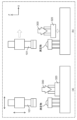
- FIG. 3 shows the state of the top probe 200 during measurement.
- a measurement chuck 201 provided on the main body of the apparatus includes a probe holding mechanism 113 having holding claws 202 .
- the holding claw 202 is configured to be opened and closed by an air cylinder (not shown).
- the upper surface probe 200 is positioned by pressing upward against the positioning pin 203 of the measurement chuck 201, and is held by the measurement chuck 201 by closing the holding claws 202.
- the top probe 200 includes an air bearing 205 configured to allow the stylus 56 to move in the Z direction.
- a micro air slider 55 made of an aluminum member is provided within the air bearing 205, and a stylus 56 made of aluminum is attached to the tip thereof.
- An air coupler 223 extending downward from the measurement chuck 201 is connected to the air joint 206 of the upper surface probe 200. Thereby, an air supply path is configured, and air is supplied from the measurement chuck 201 to the air bearing 205.
- the flow rate of the air supplied to the air bearing 205 is small, for example, 0.4 to 0.6 NL/min, and the air supplied to the device slowly advances through the air supply path. Therefore, the air supplied from the air coupler 223 becomes accustomed to the temperature of the upper surface probe 200, and immediately before being discharged to the atmosphere via the air bearing 205, the air is the same as that of the upper surface probe.
- the supplied air passes through a fine gap of around 10 ⁇ m in the air bearing 205 and is released to the atmosphere from the upper circular air protrusion and the lower circular air protrusion. That is, the pressure of the compressed air decreases due to rapid release to the atmosphere, and the released air loses heat due to adiabatic expansion, causing a slight temperature drop of 1° C. or less around the micro air slider 55. If the lengths of the micro air slider 55 and stylus 56 in the Z direction continue to change due to this temperature drop, measurement errors will occur. However, since the upper surface probe 200 is exposed to the measurement environment temperature of the surrounding area where it is installed and is supplied with heat by the air in the surrounding area, the temperature does not continue to drop and continues to maintain a constant temperature. Therefore, highly accurate measurement can be performed.
- FIG. 4 shows the state of the top probe 200 during storage.
- the upper surface probe 200 is stored by a storage stand 221 and a storage chuck 220.
- the storage stand 221 and the storage chuck 220 constitute a storage mechanism.
- the upper surface probe 200 is urged from the bottom to the top by the storage table 221, is pressed against the storage chuck 220, and is positioned by the positioning pin 222.
- the upper surface probe 200 is provided with an air joint 401 on the side, in addition to the air joint 206.
- the air coupler 403 is joined to the air joint 401.
- an air supply path is configured, and air is supplied from the air supply source 405 to the air bearing 205 via the heat insulating tube 404 (an example of a heat insulating structure) and the air coupler 403.
- the air supply source 405, the heat insulating tube 404, and the air coupler 403 constitute an air supply mechanism.
- Air supply source 405 is, for example, an air compressor. Note that since the air supply mechanism includes the heat insulating tube 404, it is possible to make it difficult for the heat around the air supply mechanism to be transmitted to the air passing through the heat insulating tube 404.
- the supplied air passes through the minute gap of the air bearing 205, and the pressure decreases due to the sudden release to the atmosphere, and the amount of heat is taken away due to adiabatic expansion.
- a slight temperature drop occurs around the micro air slider 55.
- the stop valve 224 provided in the air joint 401 seals the air joint 401 with an internal spring or the like so that air is not released to the atmosphere.
- the stop valve 225 provided in the air joint 206 seals the air joint 206 with an internal spring or the like so that air is not released to the atmosphere.
- the micro air slider 55 is made of a material with a small coefficient of linear expansion, such as ceramic, it is possible to perform measurements with higher accuracy. However, it is not easy to process the cylindrical micro air slider 55 with high precision, which increases the cost. Furthermore, if the upper surface probe 200 comes into contact with an object to be measured due to an operational error, it is likely to break, making it difficult to handle in terms of repair costs and repair time. On the other hand, aluminum has good workability and can be processed with high precision, and there is no risk of cracking. Furthermore, since the stylus 56 also requires periodic replacement, it is desirable to be made of aluminum in order to reduce running costs.
- FIG. 5 shows another example of the state of the top probe 200 during storage.
- the upper probe 200 is not provided with an air joint 401 on the side.
- the storage chuck 220 includes an air coupler 223A extending downward.
- the air coupler 223A is joined to the air joint 206. This forms an air supply path, and air is supplied from the air coupler 223A to the air bearing 205.
- air supply during storage may be performed via the air joint 206 above the top probe 200, similar to the air supply during measurement.
- the air joint 206 is located away from the central axis of the upper surface probe 200.
- another air joint may be provided in the upper surface probe 200, for example, in the area where it comes into contact with the positioning pin 222, and air may be supplied through this air joint during storage.
- the air joint is located near the center of the upper surface probe 200 at a position away from the central axis.
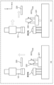
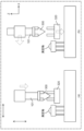
- FIG. 6 shows the state of the side probe 300 during measurement.
- the side probe 300 measures the shape of the object from the X and Y directions.
- a measuring chuck 201 provided on the main body of the apparatus includes a holding claw 202 configured to be opened and closed by an air cylinder (not shown).
- the side probe 300 is positioned by pressing upward against the positioning pin 203 of the measurement chuck 201, and is held by the measurement chuck 201 by closing the holding claws 202.
- the side movable portion 301 is supported by a fulcrum 302 at the recessed portion of the Y-direction support 310, and is rotatably movable in ⁇ (around the X-axis) and ⁇ (around the Y-axis).
- the Y-direction support 310 is fixed to the side probe 300.
- a side surface stylus 303 that contacts the measurement surface is set at the tip of the side surface movable section 301 . By contacting the side surface stylus 303 in the XY directions, the side surface movable portion 301 rotates in the ⁇ direction about the fulcrum 302.
- the position of the fulcrum 302 is maintained in a state in which there is no heat source such as an air supply source or an actuator around it, and it is adapted to the surrounding temperature environment. Therefore, the XY position of the fulcrum 302 does not change, and it is possible to perform highly accurate position measurement in the X and Y directions using the fulcrum 302 as a reference.
- the tilt optical system 10 like the top probe 200, is used to detect the tilt of the side surface.
- the laser beam irradiated from the tilt optical system 10 passes through a tilt measurement optical path 305 and is incident on a side mirror 304 provided at the upper end of the side movable section 301 .
- the light reflected by the side mirror 304 passes through the tilt measurement optical path 305 again and is detected by the tilt optical system 10.
- a movable magnet 306 is provided at the upper end of the side surface movable portion 301, and a fixed magnet 307 is provided on the casing of the side surface probe 300 at a position opposite to this.
- the fixed magnet 307 is movable in the XY directions by an XY position fine adjustment mechanism 308.
- the XY position of the fixed magnet 307 is adjusted by the XY position fine adjustment mechanism 308, and the ⁇ and ⁇ rotations of the side movable part 301 are adjusted so that the irradiated laser beam returns to the center of the tilted optical system 10. This adjustment is performed with the device powered on and the side probe 300 attached to the device body. After the adjustment, the XY position adjusted by the XY position fine adjustment mechanism 308 is locked.
- FIG. 7 shows the state of the side probe 300 during storage.
- the side probe 300 is placed on and held on the storage stand 320. During storage, there is no need to supply air or drive the actuator, and the device can be stored in a thermally stable state.
- the top probe 200 is stored on a storage stand 221.
- the upper surface probe 200 is fixed to a storage stand 221 by a storage chuck 220.
- the state in which the air coupler 403 is joined to the air joint 401 and air is supplied to the air bearing 205 is maintained. This makes it possible to maintain a constant decrease in the amount of heat due to adiabatic expansion of air released into the atmosphere.
- FIG. 9(a) move the storage chuck 220 upward.
- FIG. 9(b) the storage chuck 220 is moved to the right in the drawing, and the storage stand 221 is raised. Then, the Z-axis stage section 101 attached to the XY stage (not shown) is moved to the position where the upper surface probe 200 is taken out.
- the Z-axis stage section 101 is moved downward and the holding claw 202 (see FIG. 3) of the probe holding mechanism 113 is hooked onto the upper surface probe 200.
- the XYZ position and the rotational position around the XYZ axes be determined using three positioning pins and a kinematic structure in which a V-shaped groove is formed.
- Air coupler 223 is coupled to air joint 206 (see FIG. 3) of top probe 200. This forms an air supply path and supplies air to the air bearing 205.
- a stop valve 224 provided on the side of the top probe 200 seals air from being released to the atmosphere.
- the Z-axis stage section 101 is moved upward and the upper surface probe 200 is lifted up. Thereafter, the storage stand 221 is lowered, and the Z-axis stage section 101 is further moved to the left in the drawing. A cover (not shown) is placed over the top to store the storage stand 221.
- the top surface probe 200 attached to the Z-axis stage section 101 measures the surface shape of the object to be measured.
- Servo is applied in the Z direction by the linear motor 20 so that the measuring force when the stylus 56 contacts the object to be measured is constant (this state is called servo-on. Also, stopping the servo from the servo-on state is called servo-off). call). While the servo is turned on, it scans in the XY directions and measures the laser length in the XYZ axes. The acquired XYZ coordinate measurement data point sequence A is saved.
- a fixed reference sphere 114 (see FIG. 1) fixedly provided on the surface plate 110 is scanned from above in the XY direction, and the fixed reference ball 114 is scanned from above in the The center coordinates A of the sphere 114 are calculated and stored in memory.
- the top probe 200 is returned to the storage stand 221 by reversing the procedure described above.
- the storage chuck 220 is transferred to the upper part of the upper surface probe 200.
- the air coupler 403 is joined to the air joint 401 on the side of the upper surface probe 200. Air supply is started, and air is supplied to the air bearing 205 to maintain the same temperature environment during storage as during measurement.
- the method of supplying air during storage is different.
- the probe can be replaced using the same procedure.
- the side probe 300 is installed on a storage stand 320. As shown in FIG. 12(b), the storage stand 320 is raised. Then, the Z-axis stage section 101 attached to the XY stage (not shown) is moved to the position where the side probe 300 is taken out.
- the Z-axis stage part 101 is moved downward and the holding claw 202 (see FIG. 6) is hooked onto the side probe 300.
- the XYZ position and the rotational position around the XYZ axes be determined using three positioning pins and a kinematic structure in which a V-shaped groove is formed.
- the Z-axis stage section 101 is moved upward and the side probe 300 is lifted up. Thereafter, the storage stand 320 is lowered, and the Z-axis stage section 101 is further moved to the left in the drawing. A cover (not shown) is placed over the top to store the storage stand 320.
- the side surface shape of the object to be measured is measured by the side probe 300 attached to the Z-axis stage section 101.
- a linear motor (not shown) applies servo in the XY directions so that the measuring force when the side stylus 306 contacts the object to be measured in the XY directions is constant (this state is called XY servo on. Stopping the servo from this state is called XY servo off). While turning on the XY servo, scan in the XY direction and measure the laser length of the XYZ axes. The acquired XYZ coordinate measurement data point sequence B is saved.
- the fixed reference sphere 114 fixedly provided on the surface plate 110 is scanned so as to rotate in the circumferential direction on, for example, the XY plane, and the measured data is The center coordinates B of the fixed reference sphere 114 are calculated and stored in memory.
- the measurement data point sequence A obtained using the top probe 200 and the measurement data point sequence B obtained using the side probe 300 are combined to obtain three-dimensional shape data of the object to be measured.
- the coordinates of the measurement data point sequence A and the measurement data point sequence B are converted so that the center coordinate A obtained by the top probe 200 and the center coordinate B obtained by the side probe 300 match, and the three-dimensional shape is Generate data.
- the three-dimensional shape of both the top and side surfaces of the object can be measured with ultra-high precision of 1 to 100 nanometers.
- the present invention is useful for realizing highly accurate three-dimensional measurement in shape measurement using a measurement probe with an air bearing.
Abstract
保管装置は、形状測定装置によって使用される測定用プローブを保管する。測定用プローブは、測定物に接触させるスタイラスが移動可能に構成されたエアーベアリングを有する。保管装置は、測定用プローブを保管するための保管機構と、測定用プローブが保管機構に保管されたとき、エアーベアリングにエアーを継続的に供給するように構成されたエアー供給機構とを備える。
Description
本発明は、光学部品または金型等の被測定面の位置情報を得る3次元形状測定装置において用いられる、接触式の形状測定用プローブの保管装置に関するものである。
光学部品または金型などの非球面形状になっている表面形状を高精度に測定する方法として、3次元形状測定機の利用が広く知られている。一般に、接触式の測定用プローブを有する3次元形状測定機は、測定用プローブの先端を被測定物に接触させながら被測定物の表面に沿って測定用プローブを移動させ、測定用プローブと基準面との位置関係から被測定物の表面形状を測定するものである。このような測定機の1つとして、レーザ測長器と基準平面ミラーとを利用した3次元形状測定機がある。
従来の3次元測定機としては、プローブを2つ併設し形状測定を行うものがあった(例えば、特許文献1参照)。
しかしながら、従来の構成では、上面用プローブと側面用プローブをX方向にずらした位置で設置する。上面用プローブで測定する場合と、側面用プローブで測定する場合に、XYステージで測定物に対するX位置をずらし、測定する。上面用プローブによる測定中は、その測定エリアから側面用プローブを退避させる必要があり、側面用プローブによる測定中に、その測定エリアから上面用プローブを退避させる必要があった。これにより、測定サンプルがXY方向に大きい場合、装置が大型化し、高コスト化してしまうという問題点があった。
そこで、プローブのチャック部分を1つにし、上面用プローブと側面用プローブを交換式にすることによって、プローブ交換の手間が増えるものの、装置全体のコストは低く抑えることができる。
ところが、エアーベアリング方式の測定プローブを交換式にした場合には、次のような問題が生じる。測定プローブの保管時は、エアーベアリングにエアーが供給されている使用時に比べて、先端部分でエアーが大気中に放出される際の断熱膨張による冷却効果が生じない。このため、温度上昇が発生し、プローブ先端部分で熱膨張が発生し、これにより、測定時に継続的な先端部分の変形が発生し、0.1μmのオーダーでの測定精度が維持できない。
本発明は、従来の課題を解決するものであり、エアーベアリングを有する測定プローブについて、測定精度を維持可能にするための保管装置および保管方法を提供することを目的とする。
本発明の一態様では、形状測定装置によって使用される測定用プローブを保管する保管装置であって、前記測定用プローブは、測定物に接触させるスタイラスが移動可能に構成されたエアーベアリングを有し、前記保管装置は、前記測定用プローブを保管するための保管機構と、前記測定用プローブが前記保管機構に保管されたとき、前記エアーベアリングにエアーを継続的に供給するように構成されたエアー供給機構とを備える。
この構成によると、測定用プローブを使用せず保管するときも、エアー供給機構によって、エアーベアリングにエアーが継続的に供給される。これにより、使用時と同様に、エアーベアリングからエアーが大気に放出され、断熱膨張が起き冷却される状態が維持される。したがって、保存時の温度上昇を防止でき、測定用プローブのマイクロスライダからスタイラスまでの長さを一定に維持することができ、高精度な測定を行うことができる。
本発明によると、保管時の測定用プローブの温度上昇を抑えることができ、高精度な測定を実現することができる。
以下、本発明の実施の形態について、図面を参照しながら説明する。
(実施形態)
図1は実施形態に係る形状測定装置の概略構成を示す図である。図1に示す形状測定装置100は、上面測定用プローブ(適宜、上面プローブと略記する)および側面測定用プローブ(適宜、側面プローブと略記する)を用いて、測定物の3次元形状を測定する装置である。図2はZ軸ステージ部101の構成を示す図である。
図1は実施形態に係る形状測定装置の概略構成を示す図である。図1に示す形状測定装置100は、上面測定用プローブ(適宜、上面プローブと略記する)および側面測定用プローブ(適宜、側面プローブと略記する)を用いて、測定物の3次元形状を測定する装置である。図2はZ軸ステージ部101の構成を示す図である。
形状測定装置100は、XYステージ(図示せず)と、Z軸ステージ部101と、制御部(図示せず)とを備えている。XYステージは、定盤110上にXY軸方向に移動可能に配置され、測定ユニット103aをXY軸方向に移動可能としている。Z軸ステージ部101は、定盤110にZ軸方向すなわち上下方向(鉛直方向)に移動可能に支持され、測定物の測定面に接触させるプローブ部3を下端に支持して、プローブ部3を上下移動可能としている。制御部は、フォーカス光学系4、XYステージ、Z軸ステージ部101、および、He-Neレーザ64等に接続され、それぞれの動作制御を行うことにより、3次元形状測定動作を制御している。この際、制御部は、プローブ部3によるZ方向の接触力が一定となるように、Z軸ステージ部101を制御する。
測定ユニット103aから、X軸測長用レーザ光がX軸方向ミラー115に照射され、Y軸測長用レーザ光がY軸方向ミラー(図示せず)に照射される。測定ユニット103aをXYステージによってX軸方向およびY軸方向に移動させながら、プローブ部3を測定物に接触させる。プローブ部3の移動をZ軸ステージ部101に連結された光学系によって検出し、測定物の3次元形状を測定する。
したがって、形状測定装置100は、プローブ部3の測定面をXY方向に動かすXYステージと、プローブ部3をZ方向に動かすZ軸ステージ部101とにより、測定物の測定面とプローブ部3の相対位置をXYZ方向に動かすようにしている。
Z軸ステージ部101は、プローブ部3およびフォーカス光学系4に加えて、エアースライダ外枠1、エアースライダ中空軸2、2つの支持アーム5、2つの駆動部7、2つの支持部8等を備えている。
フォーカス光学系4は、He-Neレーザ64を少なくとも有する光学系であり、エアースライダ中空軸2に設けられている。図2に示すように、フォーカス光学系4は、He-Neレーザ64と、半導体レーザ光学系50と、ダイクロイックミラー52と、コリメーターレンズ53と、ミラー54とで大略構成されている。半導体レーザ光学系50およびダイクロイックミラー52は、エアースライダ中空軸2の上端に配置されている。コリメーターレンズ53およびミラー54は、エアースライダ中空軸2の下端に配置されている。ミラー54は、プローブ部3のマイクロスライダ55で支持されたスタイラス56の上端に固定されている。
さらに、傾き光学系10が、エアースライダ中空軸2に、フォーカス光学系4の光路の空間内に併設するように備えられている。傾き光学系10は、傾き光学系用の半導体レーザ(図示せず)と、ミラー54とで構成されている。プローブ部3の鏡筒の中に設置されたマイクロスライダ55が傾いた場合、傾き光学系10から出た光が、マイクロスライダ55の上面のミラー54で反射し、この変化を検出して傾き補正を行う。
エアースライダ中空軸2は、上下方向に縦長の直方体筒形状の部材であり、Z軸ステージ部101のZ軸駆動軸として機能する。エアースライダ中空軸2は、上端にフォーカス光学系4が配置され、下端にプローブ部3が配置されている。エアースライダ中空軸2の中心部には貫通穴6があり、貫通穴6内に、フォーカス光学系4とプローブ部3の上端のミラー54とを結ぶ光路が形成されている。一例として、エアースライダ中空軸2は、セラミックなどの断熱材で構成する。例えば、後述するコイル21の熱が支持アーム5を介して伝達しても、断熱材によって断熱されて、エアースライダ中空軸2には熱が伝わらない。これにより、エアースライダ中空軸2の熱による湾曲を防止することができる。
駆動部7は、各支持アーム5のエアースライダ中空軸2の近傍の位置に、エアースライダ中空軸2の中心軸に対して対称に配置されている。駆動部7は、エアースライダ外枠1に対して2つの支持アーム5を介してエアースライダ中空軸2を軸方向に駆動可能としている。一対の駆動部7は、エアースライダ中空軸2の中心軸に対して対称形となっている。ここでは、各駆動部7は、アクチュエータの一例であるリニアモータ20によって構成されている。図2に示すように、各支持アーム5の先端には、エアパッド28を介して、エアシリンダ27が接続されている。
リニアモータ20は、四角枠状に形成されたコイル21と、磁石(図示せず)とによって構成されており、制御部によって駆動制御される。各支持アーム5のエアースライダ中空軸2の近傍の位置にコイル21が配置され、コイル21の軸方向の中央部に支持アーム5が連結されている。コイル21は、中央ヨーク(図示せず)の外側に嵌合されて上下方向に自在に移動可能となっている。コイル21には、所定の駆動電流が印加され、これにより、固定側の中央ヨークに対してエアースライダ中空軸2を上下方向に移動させる。このように、本実施形態で使用するリニアモータ20は、コイル21が支持アーム5に支持され、磁石をエアースライダ外枠1に固定した可動コイル方式としている。よって、比較的重い磁石を固定側とし、比較的軽いコイルを可動側とすることによって、全体として、リニアモータ20の可動部分の重量を軽くすることができる。また、回転モーメントも抑制することができ、モータに加わる消費電力を抑えることができ、熱変形が抑えられる。
測定ユニット103aの上面側に、Z方向の高さを測定するためのミラー54が設けられている。プローブ部3のZ方向の高さは、波長633nmの周波数安定化レーザをスケールとし、ミラー54の面の位置を測定することにより、直接測定される。周波数安定化レーザの空気の温度変化による波長変化率いわゆる線膨張係数は、測定ユニット103aの機構部分を構成しているアルミ、鉄等の線膨張係数に比べ1/20~1/10程度に小さい。このため、測定ユニット103aを構成している機構部分が温度変化により熱変形を起こした場合でも、温度による測定値の変化による測定誤差は、小さく抑えることが可能である。
また、形状測定装置100は、測定用プローブを保管する保管装置70を備える。保管装置70は、図1では簡略化しているが、測定用プローブを保管するための保管機構と、測定用プローブが保管機構に保管されたとき、エアーベアリングにエアーを継続的に供給するように構成されたエアー供給機構とを備える。なお、図1に示すように、保管装置70に保管されたプローブのスタイラスの先端位置の高さを、測定用のプローブ部3のスタイラスの先端位置の高さに合わせると良い。これにより、測定時と保管時とで、スタイラス間の温度変化を抑制することができる。
<上面測定用プローブ>
図3は測定時における上面プローブ200の状態を示す。装置本体に設けられた測定用チャック201は、保持爪202を有するプローブ保持機構113を備える。保持爪202は、エアシリンダ(図示せず)によって開閉するように構成されている。上面プローブ200は、測定用チャック201の位置決めピン203に上方向に押しつけることによって位置決めされ、保持爪202が閉じることによって、測定用チャック201に保持される。
図3は測定時における上面プローブ200の状態を示す。装置本体に設けられた測定用チャック201は、保持爪202を有するプローブ保持機構113を備える。保持爪202は、エアシリンダ(図示せず)によって開閉するように構成されている。上面プローブ200は、測定用チャック201の位置決めピン203に上方向に押しつけることによって位置決めされ、保持爪202が閉じることによって、測定用チャック201に保持される。
上面プローブ200は、スタイラス56がZ方向に移動できるように構成されたエアーベアリング205を備えている。エアーベアリング205内に、アルミ部材で構成されたマイクロエアースライダ55が設けられており、その先端にアルミで構成されたスタイラス56が取り付けられている。測定用チャック201から下方に延びるエアーカプラ223が、上面プローブ200のエアージョイント206に接続される。これにより、エアー供給経路が構成され、測定用チャック201からエアーベアリング205にエアーが供給される。
ここで、エアーベアリング205に供給するエアーの流量は例えば0.4~0.6NL/minと少なく、装置に供給されたエアーは、エアー供給経路をゆっくり進んでいく。このため、エアーカプラ223から供給されたエアーは、上面プローブ200の温度に馴染んでいき、エアーベアリング205を経て大気に放出される直前では、上面プローブと同一である。
供給されたエアーは、エアーベアリング205の10μm前後の微細なギャップを通過し、上方の円形のエアー突出部と下方の円形のエアー突出部とから、大気に開放される。すなわち、圧縮されたエアーは、急激な大気開放により圧力が低下し、発散したエアーは断熱膨張により熱量を奪われ、マイクロエアースライダ55の周辺では、1℃以下の微小な温度低下が発生する。この温度低下により、マイクロエアースライダ55およびスタイラス56のZ方向の長さが変化し続けると、測定誤差になる。しかし、上面プローブ200は設置された周辺部の測定環境温度にさらされており、周辺部分の空気により熱量を供給されているため、温度は下がり続けることはなく、一定の温度を維持し続ける。したがって、高精度な測定を行うことができる。
図4は保管時における上面プローブ200の状態を示す。上面プローブ200は、保管台221および保管用チャック220によって保管される。本実施形態では、保管台221および保管用チャック220によって、保管機構が構成されている。上面プローブ200は、下方から上方に向けて保管台221より付勢され、保管用チャック220に押し当てられており、位置決めピン222によって位置決めされている。
ここで、本実施形態では、上面プローブ200は、エアージョイント206とは別に、側部にエアージョイント401が設けられている。図4に示すように、上面プローブ200の保管時において、エアーカプラ403が、エアージョイント401に接合される。これにより、エアー供給経路が構成され、エアー供給源405から、断熱チューブ404(断熱構造の一例)およびエアーカプラ403を介して、エアーベアリング205にエアーが供給される。本実施形態では、エアー供給源405、断熱チューブ404およびエアーカプラ403によって、エアー供給機構が構成されている。エアー供給源405は、例えば、エアーコンプレッサである。なお、エアー供給機構が断熱チューブ404を備えていることにより、断熱チューブ404内を通過するエアーに、エアー供給機構の周囲の熱を伝えにくくすることができる。
すなわち、保管時においても測定時と同様に、供給されたエアーは、エアーベアリング205の微細なギャップを通過し、急激な大気開放により圧力が低下し、断熱膨張により熱量を奪われ、このため、マイクロエアースライダ55の周辺では微小な温度低下が発生する。この構成により、測定時と同様の温度環境が維持され、マイクロエアースライダ55およびスタイラス56は、長さが変化することなく、一定長さで維持、保管される。
なお、測定時には、エアージョイント401に設けられたストップ弁224が、エアーが大気側に放出されないように、内部のバネ等によってエアージョイント401を封止する。保管時には、エアージョイント206に設けられたストップ弁225が、エアーが大気側に放出されないように、内部のバネ等によってエアージョイント206を封止する。
なお、マイクロエアースライダ55を、セラミック等の線膨張係数の小さい材料で構成すると、より精度高く測定を行うことが可能となる。ただし、円筒形のマイクロエアースライダ55を高精度に加工するのは容易でなく、コストが高くなる。また、上面プローブ200を操作ミスで測定物等に接触させた場合は、割れやすく、修理コストや修理期間のことを考えると、扱いにくい。一方、アルミは加工性が良く、高精度な加工が可能であり、また割れるおそれもない。また、スタイラス56も、定期的な交換が必要であるので、ランニングコストを抑えるために、アルミで構成することが望ましい。
図5は保管時における上面プローブ200の状態の他の例である。図5の例では、上面プローブ200は、側部にエアージョイント401は設けられていない。図5に示すように、保管用チャック220は、下方に延びるエアーカプラ223Aを備える。上面プローブ200の保管時において、エアーカプラ223Aが、エアージョイント206に接合される。これにより、エアー供給経路が構成され、エアーカプラ223Aからエアーベアリング205にエアーが供給される。
図5に示すように、保管時におけるエアー供給は、測定時におけるエアー供給と同様に、上面プローブ200の上側にあるエアージョイント206を介して行ってもよい。なお、エアージョイント206は、上面プローブ200の中心軸より離れた位置にある。あるいは、上面プローブ200の、例えば位置決めピン222と当接するあたりに、別のエアージョイントを設けて、保管時にはこのエアージョイントを介してエアー供給を行うようにしてもよい。この場合、エアージョイントは、上面プローブ200の中心軸より離れた位置の中央部近辺にある。
<側面測定用プローブ>
図6は測定時における側面プローブ300の状態を示す。側面プローブ300は、XY方向から測定物の形状を測定する。装置本体に設けられた測定用チャック201は、エアシリンダ(図示せず)によって開閉するように構成された保持爪202を備える。側面プローブ300は、測定用チャック201の位置決めピン203に上方向に押しつけることによって位置決めされ、保持爪202が閉じることによって、測定用チャック201に保持される。
図6は測定時における側面プローブ300の状態を示す。側面プローブ300は、XY方向から測定物の形状を測定する。装置本体に設けられた測定用チャック201は、エアシリンダ(図示せず)によって開閉するように構成された保持爪202を備える。側面プローブ300は、測定用チャック201の位置決めピン203に上方向に押しつけることによって位置決めされ、保持爪202が閉じることによって、測定用チャック201に保持される。
側面可動部301は、Y方向支柱310のへこみ部分で支点302によって支持され、α(X軸周り)、β(Y軸周り)に回転移動可能である。Y方向支柱310は側面プローブ300に固定されている。側面可動部301の先端部分に、測定面に接触する側面用スタイラス303がセットされている。側面用スタイラス303がXY方向に接触することにより、側面可動部301は支点302を回転中心とし、αβ方向に回転運動を行う。
支点302の位置は、その周辺にエアー供給源やアクチュエータ等の熱源がなく、周辺の温度環境に馴染んだ状態で維持されている。このため、支点302のXY位置が変化することはなく、この支点302を基準にして高精度なXY方向の位置計測を行うことが可能である。
傾き光学系10は、上面プローブ200と同様に、側面の傾き検出に使用される。傾き光学系10から照射されたレーザ光は、傾き測定用光路305を経て、側面可動部301の上端に設けられた側面ミラー304に入射される。側面ミラー304で反射した光は、再度、傾き測定用光路305を経由し、傾き光学系10によって検出される。
側面可動部301の上端に、可動マグネット306が設けられており、これと対になる位置で、側面プローブ300の筐体に固定マグネット307が設けられている。固定マグネット307は、XY位置微調機構308によって、XY方向に移動可能になっている。
固定マグネット307のXY位置をXY位置微調機構308によって調整し、照射されたレーザ光が傾き光学系10の中央部に返るように、側面可動部301のα,β回転を調整する。この調整は装置に電源を投入し、側面プローブ300を装置本体に取り付けた状態で行う。調整後、XY位置微調機構308で調整したXY位置はロックしておく。
図7は保管時における側面プローブ300の状態を示す。側面プローブ300は、保管台320の上に載置され、保持される。保管時は、エアー供給およびアクチュエータの駆動等の必要はなく、熱的にも安定した状態で保存が可能である。
<プローブ交換手順>
(上面プローブ交換)
上面プローブの交換手順について、図8~図11を用いて説明する。ここでは、図3および図4に示す上面プローブ200を用いるものとする。
(上面プローブ交換)
上面プローブの交換手順について、図8~図11を用いて説明する。ここでは、図3および図4に示す上面プローブ200を用いるものとする。
図8(a)に示すように、上面プローブ200は保管台221に保管されている。上面プローブ200は、保管用チャック220によって、保管台221に固定されている。このとき、上面プローブ200は、エアーカプラ403がエアージョイント401に接合されて、エアーベアリング205にエアーが供給された状態が維持される。これにより、大気に放出されるエアーの断熱膨張による熱量の低下を一定に維持することができる。
図8(b)に示すように、エアーカプラ403を図面右方向に移動させて、エアージョイント401から外す。これにより、エアーベアリング205へのエアー供給経路が切断され、上面プローブ200は移動可能な状態になる。
図9(a)に示すように、保管用チャック220を上方に移動させる。図9(b)に示すように、保管用チャック220を図面右方向に移動させ、保管台221を上昇させる。そして、XYステージ(図示せず)に取り付けられたZ軸ステージ部101を、上面プローブ200の取り出し位置に移動させる。
図10(a)に示すように、Z軸ステージ部101を下方に移動させ、プローブ保持機構113の保持爪202(図3参照)を上面プローブ200に引っ掛ける。この際、位置決めピン3本を用い、V字溝が形成されたキネマチック構造によって、XYZ位置とXYZ軸周りの回転位置が位置決めされることが望ましい。エアーカプラ223を、上面プローブ200のエアージョイント206(図3参照)に結合する。これにより、エアー供給経路が構成され、エアーベアリング205にエアーが供給される。上面プローブ200の側部に設けられたストップ弁224は、エアーが大気側に放出されないように封止する。
図10(b)に示すように、Z軸ステージ部101を上方に移動させ、上面プローブ200を吊り上げる。その後、保管台221を降下させ、さらに、Z軸ステージ部101を図面左方向に移動させる。カバー(図示せず)を上部からかけ、保管台221の収納を行う。
図11に示すように、Z軸ステージ部101に取り付けられた上面プローブ200によって、測定物の表面形状を測定する。スタイラス56が測定物に接する際の測定力を一定にするように、リニアモータ20によってZ方向にサーボをかける(この状態をサーボオンと呼ぶ。また、サーボオンの状態からサーボを停止することをサーボオフと呼ぶ。)。サーボオンしながら、XY方向に走査し、XYZ軸のレーザ測長を測定する。取得したXYZ座標の測定データ点列Aを保存する。
なお、上面プローブ200の交換後は、スタイラス56の先端位置は、マイクロメートル以下の精度では、再現性が維持されておらず、正確な位置になっていない。このため、測定データにミクロンオーダーの位置ずれが発生し、測定精度が悪化する。これを防止するために、測定物の測定の前に、定盤110上に固定した状態で設けられた固定基準球114(図1参照)を上方よりXY方向に走査し、測定データから固定基準球114の中心座標Aを算出し、メモリに記憶する。
測定後、上述した手順と逆の手順で、上面プローブ200を保管台221に戻す。保管用チャック220を上面プローブ200の上部に移載する。位置決めピン222での位置決めにより、エアーカプラ403を、上面プローブ200の側部にあるエアージョイント401に接合する。エアー供給を開始し、エアーベアリング205にエアーを供給し、保管時も測定時と同様の温度環境を維持する。
なお、図5に示す上面プローブを用いる場合には、保管時におけるエアー供給の方法が異なる。ただし、それ以外は、同様の手順でプローブ交換を行えばよい。
(側面プローブ交換)
側面プローブの交換手順について、図12~図14を用いて説明する。
側面プローブの交換手順について、図12~図14を用いて説明する。
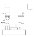
図12(a)に示すように、側面プローブ300は保管台320に設置されている。図12(b)に示すように、保管台320を上昇させる。そして、XYステージ(図示せず)に取り付けられたZ軸ステージ部101を側面プローブ300の取り出し位置に移動させる。
図13(a)に示すように、Z軸ステージ部101を下方に移動させ、保持爪202(図6参照)を側面プローブ300に引っ掛ける。この際、位置決めピン3本を用い、V字溝が形成されたキネマチック構造によって、XYZ位置とXYZ軸周りの回転位置が位置決めされることが望ましい。
図13(b)に示すように、Z軸ステージ部101を上方に移動させ、側面プローブ300を吊り上げる。その後、保管台320を降下させ、さらに、Z軸ステージ部101を図面左方向に移動させる。カバー(図示せず)を上部からかけ、保管台320の収納を行う。
図14に示すように、Z軸ステージ部101に取り付けられた側面プローブ300によって、測定物の側面形状を測定する。側面スタイラス306が測定物にXY方向に接する際の測定力を一定にするように、リニアモータ(図示せず)によって、XY方向にサーボをかける(この状態をXYサーボオンと呼ぶ。また、XYサーボオンの状態からサーボを停止することをXYサーボオフと呼ぶ)。XYサーボオンしながら、XY方向に走査し、XYZ軸のレーザ測長を測定する。取得したXYZ座標の測定データ点列Bを保存する。
なお、側面プローブ300の交換後は、側面用スタイラス303の先端位置は、マイクロメートル以下の精度では、再現性が維持されておらず、正確な位置になっていない。このため、測定データにミクロンオーダーの位置ずれが発生し、測定精度が悪化する。これを防止するために、測定物の測定の前に、定盤110上に固定した状態で設けられた固定基準球114を、例えばXY平面で周方向に回転するように走査し、測定データから固定基準球114の中心座標Bを算出し、メモリに記憶する。
測定後、上述した手順と逆の手順で、側面プローブ300を保管台320に戻す。
(測定後のデータ合成)
測定後、上面プローブ200を用いて得た測定データ点列Aと、側面プローブ300を用いて得た測定データ点列Bとを合成して、測定物の3次元形状データを取得する。このとき、上面プローブ200によって得た中心座標Aと、側面プローブ300によって得た中心座標Bとが一致するように、測定データ点列Aと測定データ点列Bの座標を変換し、3次元形状データを生成する。
測定後、上面プローブ200を用いて得た測定データ点列Aと、側面プローブ300を用いて得た測定データ点列Bとを合成して、測定物の3次元形状データを取得する。このとき、上面プローブ200によって得た中心座標Aと、側面プローブ300によって得た中心座標Bとが一致するように、測定データ点列Aと測定データ点列Bの座標を変換し、3次元形状データを生成する。
このような測定により、測定物の上面および側面の両方とも、1~100ナノメートルの超高精度で、3次元形状を測定することができる。
本発明は、エアーベアリングを有する測定プローブを用いる形状測定において、高精度な3次元測定を実現するのに有用である。
56 スタイラス
70 保管装置
100 形状測定装置
200 上面プローブ
220 保管用チャック
221 保管台
205 エアーベアリング
403 エアーカプラ
404 断熱チューブ
405 エアー供給源
70 保管装置
100 形状測定装置
200 上面プローブ
220 保管用チャック
221 保管台
205 エアーベアリング
403 エアーカプラ
404 断熱チューブ
405 エアー供給源
Claims (4)
- 形状測定装置によって使用される測定用プローブを保管する保管装置であって、
前記測定用プローブは、測定物に接触させるスタイラスが移動可能に構成されたエアーベアリングを有し、
前記保管装置は、
前記測定用プローブを保管するための保管機構と、
前記測定用プローブが前記保管機構に保管されたとき、前記エアーベアリングにエアーを継続的に供給するように構成されたエアー供給機構とを備える
測定用プローブの保管装置。 - 請求項1記載の測定用プローブの保管装置であって、
前記エアー供給機構は、前記測定用プローブの側面から、エアーを供給するように構成されている
測定用プローブの保管装置。 - 請求項1記載の測定用プローブの保管装置であって
前記エアー供給機構は、
断熱構造と、
前記断熱構造を介して、前記エアーベアリングにエアーを供給するように構成されたエアー供給源と、を有している
測定用プローブの保管装置。 - 形状測定装置によって使用される測定用プローブを保管する方法であって、
前記測定用プローブは、測定物に接触させるスタイラスが移動可能に構成されたエアーベアリングを有し、
前記方法は、
前記測定用プローブを、保管機構に保管するステップと、
前記保管機構に保管された前記測定用プローブに対して、エアー供給機構によって、前記エアーベアリングにエアーを継続的に供給するステップとを備える
測定用プローブの保管方法。
Applications Claiming Priority (2)
| Application Number | Priority Date | Filing Date | Title |
|---|---|---|---|
| JP2022047392 | 2022-03-23 | ||
| JP2022-047392 | 2022-03-23 |
Publications (1)
| Publication Number | Publication Date |
|---|---|
| WO2023181474A1 true WO2023181474A1 (ja) | 2023-09-28 |
Family
ID=88100435
Family Applications (1)
| Application Number | Title | Priority Date | Filing Date |
|---|---|---|---|
| PCT/JP2022/040121 WO2023181474A1 (ja) | 2022-03-23 | 2022-10-27 | 測定プローブの保管装置および保管方法 |
Country Status (1)
| Country | Link |
|---|---|
| WO (1) | WO2023181474A1 (ja) |
Citations (3)
| Publication number | Priority date | Publication date | Assignee | Title |
|---|---|---|---|---|
| JPS6410608U (ja) * | 1987-07-07 | 1989-01-20 | ||
| JP2004340795A (ja) * | 2003-05-16 | 2004-12-02 | Olympus Corp | 測定装置のパージ機構およびそれを備えた測定装置 |
| JP2006003253A (ja) * | 2004-06-18 | 2006-01-05 | Matsushita Electric Ind Co Ltd | 測定用プローブ |
-
2022
- 2022-10-27 WO PCT/JP2022/040121 patent/WO2023181474A1/ja unknown
Patent Citations (3)
| Publication number | Priority date | Publication date | Assignee | Title |
|---|---|---|---|---|
| JPS6410608U (ja) * | 1987-07-07 | 1989-01-20 | ||
| JP2004340795A (ja) * | 2003-05-16 | 2004-12-02 | Olympus Corp | 測定装置のパージ機構およびそれを備えた測定装置 |
| JP2006003253A (ja) * | 2004-06-18 | 2006-01-05 | Matsushita Electric Ind Co Ltd | 測定用プローブ |
Similar Documents
| Publication | Publication Date | Title |
|---|---|---|
| JP3926793B2 (ja) | 表面形状測定装置 | |
| JP5281992B2 (ja) | 走査型プローブ顕微鏡及びそれを用いた計測方法 | |
| KR940003918B1 (ko) | 형상측정장치 | |
| WO2012035826A1 (ja) | 走査プローブ顕微鏡及びそれを用いた表面形状計測方法 | |
| US20100275334A1 (en) | Modular atomic force microscope | |
| US10338096B2 (en) | Metrological scanning probe microscope | |
| JP2005069972A (ja) | 走査型プローブ顕微鏡の探針移動制御方法 | |
| US20170254834A1 (en) | Modular Atomic Force Microscope | |
| US10054612B2 (en) | Optical beam positioning unit for atomic force microscope | |
| JP2012187606A (ja) | レーザ加工装置およびレーザ加工方法 | |
| WO2023181474A1 (ja) | 測定プローブの保管装置および保管方法 | |
| EP2950037B1 (en) | Three-dimensional shape measurement apparatus | |
| JP2002257523A (ja) | 超精密形状測定方法及びその装置 | |
| JP4923441B2 (ja) | 形状測定器 | |
| JP4093828B2 (ja) | 測定用プローブ及び光学式測定装置 | |
| JP5171108B2 (ja) | 三次元形状測定装置 | |
| JPH11125520A (ja) | 半導体ウエハ支持用部材及び半導体ウエハの平面度測定装置 | |
| US10705114B2 (en) | Metrological scanning probe microscope | |
| JP6799815B2 (ja) | 形状測定用プローブ | |
| CN110243290B (zh) | 通过光学干涉方法实时读取位移转动信息的三自由度纳米定位平台 | |
| JPH10267948A (ja) | 走査型プローブ顕微鏡 | |
| CN220398407U (zh) | 一种基于共聚焦显微镜的量块测量装置 | |
| Boukellal et al. | Improvement of the LNE’s metrological Atomic Force Microscope (mAFM) performance: Design of new mAFM head dedicated for nanometrology applications | |
| JP5103775B2 (ja) | 検出器、形状測定装置、及び形状測定方法 | |
| CN116625193A (zh) | 一种基于共聚焦显微镜的量块测量装置及测量方法 |
Legal Events
| Date | Code | Title | Description |
|---|---|---|---|
| 121 | Ep: the epo has been informed by wipo that ep was designated in this application |
Ref document number: 22933604 Country of ref document: EP Kind code of ref document: A1 |