WO2023181474A1 - Dispositif et procédé de rangement pour sonde de mesure - Google Patents
Dispositif et procédé de rangement pour sonde de mesure Download PDFInfo
- Publication number
- WO2023181474A1 WO2023181474A1 PCT/JP2022/040121 JP2022040121W WO2023181474A1 WO 2023181474 A1 WO2023181474 A1 WO 2023181474A1 JP 2022040121 W JP2022040121 W JP 2022040121W WO 2023181474 A1 WO2023181474 A1 WO 2023181474A1
- Authority
- WO
- WIPO (PCT)
- Prior art keywords
- air
- probe
- measurement
- storage
- measurement probe
- Prior art date
Links
- 239000000523 sample Substances 0.000 title claims abstract description 148
- 238000005259 measurement Methods 0.000 title claims abstract description 110
- 238000000034 method Methods 0.000 title claims description 22
- 230000007246 mechanism Effects 0.000 claims abstract description 28
- 238000009413 insulation Methods 0.000 claims description 2
- 230000003287 optical effect Effects 0.000 description 25
- 238000004441 surface measurement Methods 0.000 description 12
- 238000010586 diagram Methods 0.000 description 9
- 241001422033 Thestylus Species 0.000 description 7
- 210000000078 claw Anatomy 0.000 description 7
- XAGFODPZIPBFFR-UHFFFAOYSA-N aluminium Chemical compound [Al] XAGFODPZIPBFFR-UHFFFAOYSA-N 0.000 description 5
- 229910052782 aluminium Inorganic materials 0.000 description 5
- 230000008859 change Effects 0.000 description 4
- 230000007423 decrease Effects 0.000 description 3
- 239000004065 semiconductor Substances 0.000 description 3
- XEEYBQQBJWHFJM-UHFFFAOYSA-N Iron Chemical compound [Fe] XEEYBQQBJWHFJM-UHFFFAOYSA-N 0.000 description 2
- 206010037660 Pyrexia Diseases 0.000 description 2
- 239000000919 ceramic Substances 0.000 description 2
- 238000001816 cooling Methods 0.000 description 2
- 239000011810 insulating material Substances 0.000 description 2
- 238000003825 pressing Methods 0.000 description 2
- 230000008439 repair process Effects 0.000 description 2
- 230000015572 biosynthetic process Effects 0.000 description 1
- 238000005336 cracking Methods 0.000 description 1
- 230000000694 effects Effects 0.000 description 1
- 230000006870 function Effects 0.000 description 1
- 229910052742 iron Inorganic materials 0.000 description 1
- 239000000463 material Substances 0.000 description 1
- 230000000737 periodic effect Effects 0.000 description 1
- 230000008569 process Effects 0.000 description 1
- 238000003786 synthesis reaction Methods 0.000 description 1
Images


Classifications
-
- G—PHYSICS
- G01—MEASURING; TESTING
- G01B—MEASURING LENGTH, THICKNESS OR SIMILAR LINEAR DIMENSIONS; MEASURING ANGLES; MEASURING AREAS; MEASURING IRREGULARITIES OF SURFACES OR CONTOURS
- G01B21/00—Measuring arrangements or details thereof, where the measuring technique is not covered by the other groups of this subclass, unspecified or not relevant
-
- G—PHYSICS
- G01—MEASURING; TESTING
- G01B—MEASURING LENGTH, THICKNESS OR SIMILAR LINEAR DIMENSIONS; MEASURING ANGLES; MEASURING AREAS; MEASURING IRREGULARITIES OF SURFACES OR CONTOURS
- G01B5/00—Measuring arrangements characterised by the use of mechanical techniques
- G01B5/004—Measuring arrangements characterised by the use of mechanical techniques for measuring coordinates of points
- G01B5/008—Measuring arrangements characterised by the use of mechanical techniques for measuring coordinates of points using coordinate measuring machines
- G01B5/012—Contact-making feeler heads therefor
Definitions
- the present invention relates to a storage device for a contact-type shape measurement probe used in a three-dimensional shape measurement device that obtains positional information on a surface to be measured such as an optical component or a mold.
- a three-dimensional shape measuring machine is widely known as a method for measuring with high precision the shape of an aspherical surface such as an optical component or a mold.
- a three-dimensional shape measuring machine with a contact-type measurement probe moves the measurement probe along the surface of the object to be measured while keeping the tip of the measurement probe in contact with the object.
- the surface shape of the object to be measured is measured from the positional relationship with the surface.
- One such measuring device is a three-dimensional shape measuring device that uses a laser length measuring device and a reference plane mirror.
- the top surface probe and the side surface probe are installed at positions shifted in the X direction.
- the X position relative to the object to be measured is shifted on the XY stage and the measurement is performed.
- the top surface probe it is necessary to evacuate the side surface probe from the measurement area, and during measurement with the side surface probe, it is necessary to evacuate the top surface probe from the measurement area.
- the measurement sample is large in the X and Y directions, there is a problem that the apparatus becomes large and the cost becomes high.
- the cost of the entire device can be kept low, although the time and effort required to replace the probes increases.
- the air bearing type measurement probe is made replaceable, the following problems arise.
- the measurement probe is stored, compared to when it is in use when air is supplied to the air bearing, the cooling effect due to adiabatic expansion when air is released into the atmosphere at the tip does not occur.
- a temperature rise occurs and thermal expansion occurs at the tip of the probe, which causes continuous deformation of the tip during measurement, making it impossible to maintain measurement accuracy on the order of 0.1 ⁇ m.
- the present invention solves the conventional problems, and aims to provide a storage device and a storage method for maintaining measurement accuracy of a measurement probe having an air bearing.
- a storage device for storing a measurement probe used by a shape measuring device, wherein the measurement probe has an air bearing configured to allow a stylus to be moved in contact with a measurement object.
- the storage device includes a storage mechanism for storing the measurement probe, and an air pump configured to continuously supply air to the air bearing when the measurement probe is stored in the storage mechanism. A supply mechanism.
- the present invention it is possible to suppress the temperature rise of the measurement probe during storage, and it is possible to achieve highly accurate measurement.
- FIG. 1 Schematic configuration of shape measuring device according to embodiment Configuration of the Z-axis stage section in the shape measuring device shown in Figure 1 Condition of top surface measurement probe during measurement Condition of top surface measurement probe during storage
- Other examples of top surface measurement probe conditions during storage Condition of side measurement probe during measurement Condition of side measurement probe during storage are diagrams showing the procedure for replacing the top surface measurement probe.
- (a) and (b) are diagrams showing the procedure for replacing the top surface measurement probe.
- (a) and (b) are diagrams showing the procedure for replacing the top surface measurement probe.
- Diagram showing the procedure for replacing the top surface measurement probe (a) and (b) are diagrams showing the procedure for replacing the side surface measurement probe.
- (a) and (b) are diagrams showing the procedure for replacing the side surface measurement probe.
- FIG. 1 is a diagram showing a schematic configuration of a shape measuring device according to an embodiment.
- the shape measuring device 100 shown in FIG. 1 measures the three-dimensional shape of a measurement object using a top surface measurement probe (abbreviated as top surface probe when appropriate) and a side surface measurement probe (abbreviated as side surface probe as appropriate). It is a device.
- FIG. 2 is a diagram showing the configuration of the Z-axis stage section 101.
- the shape measuring device 100 includes an XY stage (not shown), a Z-axis stage section 101, and a control section (not shown).
- the XY stage is disposed on the surface plate 110 so as to be movable in the XY axes directions, and allows the measurement unit 103a to be movable in the XY axes directions.
- the Z-axis stage section 101 is supported by a surface plate 110 so as to be movable in the Z-axis direction, that is, in the vertical direction (vertical direction), and supports the probe section 3 to be brought into contact with the measurement surface of the object at its lower end. It can be moved up and down.
- the control unit is connected to the focus optical system 4, the XY stage, the Z-axis stage unit 101, the He-Ne laser 64, and the like, and controls the three-dimensional shape measurement operation by controlling the respective operations. At this time, the control section controls the Z-axis stage section 101 so that the contact force in the Z direction by the probe section 3 is constant.
- the X-axis length measurement laser beam is irradiated onto the X-axis direction mirror 115, and the Y-axis length measurement laser light is irradiated onto the Y-axis direction mirror (not shown).
- the probe section 3 is brought into contact with the object to be measured while the measurement unit 103a is moved in the X-axis direction and the Y-axis direction by the XY stage.
- the movement of the probe section 3 is detected by an optical system connected to the Z-axis stage section 101, and the three-dimensional shape of the object to be measured is measured.
- the shape measuring device 100 uses an XY stage that moves the measurement surface of the probe section 3 in the XY direction, and a Z-axis stage section 101 that moves the probe section 3 in the Z direction. I am trying to move the position in the XYZ directions.
- the Z-axis stage unit 101 includes an air slider outer frame 1, an air slider hollow shaft 2, two support arms 5, two drive units 7, two support units 8, etc. We are prepared.
- the focus optical system 4 is an optical system that includes at least a He-Ne laser 64, and is provided on the air slider hollow shaft 2. As shown in FIG. 2, the focus optical system 4 is roughly composed of a He--Ne laser 64, a semiconductor laser optical system 50, a dichroic mirror 52, a collimator lens 53, and a mirror 54.
- the semiconductor laser optical system 50 and the dichroic mirror 52 are arranged at the upper end of the air slider hollow shaft 2.
- the collimator lens 53 and mirror 54 are arranged at the lower end of the air slider hollow shaft 2.
- the mirror 54 is fixed to the upper end of a stylus 56 supported by a micro slider 55 of the probe section 3.
- a tilting optical system 10 is provided on the air slider hollow shaft 2 so as to be installed within the space of the optical path of the focusing optical system 4.
- the tilting optical system 10 includes a semiconductor laser (not shown) for the tilting optical system and a mirror 54.
- the micro slider 55 installed in the lens barrel of the probe section 3 is tilted, the light emitted from the tilt optical system 10 is reflected by the mirror 54 on the top surface of the micro slider 55, and this change is detected and the tilt is corrected. I do.
- the air slider hollow shaft 2 is a vertically elongated rectangular parallelepiped cylindrical member, and functions as a Z-axis drive shaft of the Z-axis stage section 101.
- the air slider hollow shaft 2 has a focusing optical system 4 arranged at its upper end and a probe section 3 arranged at its lower end.
- a through hole 6 is provided in the center of the air slider hollow shaft 2, and an optical path is formed in the through hole 6 to connect the focusing optical system 4 and the mirror 54 at the upper end of the probe section 3.
- the air slider hollow shaft 2 is made of a heat insulating material such as ceramic.
- the drive unit 7 is arranged symmetrically with respect to the central axis of the air slider hollow shaft 2 at a position near the air slider hollow shaft 2 of each support arm 5.
- the drive unit 7 is capable of driving the air slider hollow shaft 2 in the axial direction with respect to the air slider outer frame 1 via the two support arms 5.
- the pair of drive parts 7 are symmetrical with respect to the central axis of the air slider hollow shaft 2.
- each drive section 7 is constituted by a linear motor 20, which is an example of an actuator.
- an air cylinder 27 is connected to the tip of each support arm 5 via an air pad 28.
- FIG. 1 As shown in FIG.
- the linear motor 20 includes a coil 21 formed in the shape of a rectangular frame and a magnet (not shown), and is driven and controlled by a control section.
- a coil 21 is arranged near the air slider hollow shaft 2 of each support arm 5, and the support arm 5 is connected to the center of the coil 21 in the axial direction.
- the coil 21 is fitted on the outside of a central yoke (not shown) and is freely movable in the vertical direction.
- a predetermined drive current is applied to the coil 21, thereby moving the air slider hollow shaft 2 in the vertical direction with respect to the fixed central yoke.
- the linear motor 20 used in this embodiment has a moving coil type in which the coil 21 is supported by the support arm 5 and the magnet is fixed to the air slider outer frame 1.
- the overall weight of the movable portion of the linear motor 20 can be reduced. Moreover, rotational moment can also be suppressed, power consumption applied to the motor can be suppressed, and thermal deformation can be suppressed.
- a mirror 54 for measuring the height in the Z direction is provided on the upper surface side of the measurement unit 103a.
- the height of the probe section 3 in the Z direction is directly measured by measuring the position of the surface of the mirror 54 using a frequency stabilized laser with a wavelength of 633 nm as a scale.
- the wavelength change rate due to temperature changes in the air of the frequency stabilized laser, so-called linear expansion coefficient is about 1/20 to 1/10 smaller than the linear expansion coefficient of aluminum, iron, etc. that constitute the mechanical part of the measurement unit 103a. . Therefore, even if the mechanical parts constituting the measurement unit 103a undergo thermal deformation due to temperature changes, measurement errors due to changes in measured values due to temperature can be kept small.
- the shape measuring device 100 includes a storage device 70 that stores measurement probes.
- the storage device 70 is simplified in FIG. 1, it includes a storage mechanism for storing the measurement probe and a mechanism for continuously supplying air to the air bearing when the measurement probe is stored in the storage mechanism. and an air supply mechanism configured. Note that, as shown in FIG. 1, the height of the tip of the stylus of the probe stored in the storage device 70 may be adjusted to the height of the tip of the stylus of the measurement probe section 3. This makes it possible to suppress temperature changes between the styli during measurement and during storage.
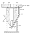
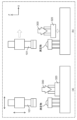
- FIG. 3 shows the state of the top probe 200 during measurement.
- a measurement chuck 201 provided on the main body of the apparatus includes a probe holding mechanism 113 having holding claws 202 .
- the holding claw 202 is configured to be opened and closed by an air cylinder (not shown).
- the upper surface probe 200 is positioned by pressing upward against the positioning pin 203 of the measurement chuck 201, and is held by the measurement chuck 201 by closing the holding claws 202.
- the top probe 200 includes an air bearing 205 configured to allow the stylus 56 to move in the Z direction.
- a micro air slider 55 made of an aluminum member is provided within the air bearing 205, and a stylus 56 made of aluminum is attached to the tip thereof.
- An air coupler 223 extending downward from the measurement chuck 201 is connected to the air joint 206 of the upper surface probe 200. Thereby, an air supply path is configured, and air is supplied from the measurement chuck 201 to the air bearing 205.
- the flow rate of the air supplied to the air bearing 205 is small, for example, 0.4 to 0.6 NL/min, and the air supplied to the device slowly advances through the air supply path. Therefore, the air supplied from the air coupler 223 becomes accustomed to the temperature of the upper surface probe 200, and immediately before being discharged to the atmosphere via the air bearing 205, the air is the same as that of the upper surface probe.
- the supplied air passes through a fine gap of around 10 ⁇ m in the air bearing 205 and is released to the atmosphere from the upper circular air protrusion and the lower circular air protrusion. That is, the pressure of the compressed air decreases due to rapid release to the atmosphere, and the released air loses heat due to adiabatic expansion, causing a slight temperature drop of 1° C. or less around the micro air slider 55. If the lengths of the micro air slider 55 and stylus 56 in the Z direction continue to change due to this temperature drop, measurement errors will occur. However, since the upper surface probe 200 is exposed to the measurement environment temperature of the surrounding area where it is installed and is supplied with heat by the air in the surrounding area, the temperature does not continue to drop and continues to maintain a constant temperature. Therefore, highly accurate measurement can be performed.
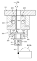
- FIG. 4 shows the state of the top probe 200 during storage.
- the upper surface probe 200 is stored by a storage stand 221 and a storage chuck 220.
- the storage stand 221 and the storage chuck 220 constitute a storage mechanism.
- the upper surface probe 200 is urged from the bottom to the top by the storage table 221, is pressed against the storage chuck 220, and is positioned by the positioning pin 222.
- the upper surface probe 200 is provided with an air joint 401 on the side, in addition to the air joint 206.
- the air coupler 403 is joined to the air joint 401.
- an air supply path is configured, and air is supplied from the air supply source 405 to the air bearing 205 via the heat insulating tube 404 (an example of a heat insulating structure) and the air coupler 403.
- the air supply source 405, the heat insulating tube 404, and the air coupler 403 constitute an air supply mechanism.
- Air supply source 405 is, for example, an air compressor. Note that since the air supply mechanism includes the heat insulating tube 404, it is possible to make it difficult for the heat around the air supply mechanism to be transmitted to the air passing through the heat insulating tube 404.
- the supplied air passes through the minute gap of the air bearing 205, and the pressure decreases due to the sudden release to the atmosphere, and the amount of heat is taken away due to adiabatic expansion.
- a slight temperature drop occurs around the micro air slider 55.
- the stop valve 224 provided in the air joint 401 seals the air joint 401 with an internal spring or the like so that air is not released to the atmosphere.
- the stop valve 225 provided in the air joint 206 seals the air joint 206 with an internal spring or the like so that air is not released to the atmosphere.
- the micro air slider 55 is made of a material with a small coefficient of linear expansion, such as ceramic, it is possible to perform measurements with higher accuracy. However, it is not easy to process the cylindrical micro air slider 55 with high precision, which increases the cost. Furthermore, if the upper surface probe 200 comes into contact with an object to be measured due to an operational error, it is likely to break, making it difficult to handle in terms of repair costs and repair time. On the other hand, aluminum has good workability and can be processed with high precision, and there is no risk of cracking. Furthermore, since the stylus 56 also requires periodic replacement, it is desirable to be made of aluminum in order to reduce running costs.
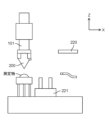
- FIG. 5 shows another example of the state of the top probe 200 during storage.
- the upper probe 200 is not provided with an air joint 401 on the side.
- the storage chuck 220 includes an air coupler 223A extending downward.
- the air coupler 223A is joined to the air joint 206. This forms an air supply path, and air is supplied from the air coupler 223A to the air bearing 205.
- air supply during storage may be performed via the air joint 206 above the top probe 200, similar to the air supply during measurement.
- the air joint 206 is located away from the central axis of the upper surface probe 200.
- another air joint may be provided in the upper surface probe 200, for example, in the area where it comes into contact with the positioning pin 222, and air may be supplied through this air joint during storage.
- the air joint is located near the center of the upper surface probe 200 at a position away from the central axis.
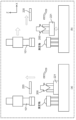
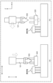
- FIG. 6 shows the state of the side probe 300 during measurement.
- the side probe 300 measures the shape of the object from the X and Y directions.
- a measuring chuck 201 provided on the main body of the apparatus includes a holding claw 202 configured to be opened and closed by an air cylinder (not shown).
- the side probe 300 is positioned by pressing upward against the positioning pin 203 of the measurement chuck 201, and is held by the measurement chuck 201 by closing the holding claws 202.
- the side movable portion 301 is supported by a fulcrum 302 at the recessed portion of the Y-direction support 310, and is rotatably movable in ⁇ (around the X-axis) and ⁇ (around the Y-axis).
- the Y-direction support 310 is fixed to the side probe 300.
- a side surface stylus 303 that contacts the measurement surface is set at the tip of the side surface movable section 301 . By contacting the side surface stylus 303 in the XY directions, the side surface movable portion 301 rotates in the ⁇ direction about the fulcrum 302.
- the position of the fulcrum 302 is maintained in a state in which there is no heat source such as an air supply source or an actuator around it, and it is adapted to the surrounding temperature environment. Therefore, the XY position of the fulcrum 302 does not change, and it is possible to perform highly accurate position measurement in the X and Y directions using the fulcrum 302 as a reference.
- the tilt optical system 10 like the top probe 200, is used to detect the tilt of the side surface.
- the laser beam irradiated from the tilt optical system 10 passes through a tilt measurement optical path 305 and is incident on a side mirror 304 provided at the upper end of the side movable section 301 .
- the light reflected by the side mirror 304 passes through the tilt measurement optical path 305 again and is detected by the tilt optical system 10.
- a movable magnet 306 is provided at the upper end of the side surface movable portion 301, and a fixed magnet 307 is provided on the casing of the side surface probe 300 at a position opposite to this.
- the fixed magnet 307 is movable in the XY directions by an XY position fine adjustment mechanism 308.
- the XY position of the fixed magnet 307 is adjusted by the XY position fine adjustment mechanism 308, and the ⁇ and ⁇ rotations of the side movable part 301 are adjusted so that the irradiated laser beam returns to the center of the tilted optical system 10. This adjustment is performed with the device powered on and the side probe 300 attached to the device body. After the adjustment, the XY position adjusted by the XY position fine adjustment mechanism 308 is locked.
- FIG. 7 shows the state of the side probe 300 during storage.
- the side probe 300 is placed on and held on the storage stand 320. During storage, there is no need to supply air or drive the actuator, and the device can be stored in a thermally stable state.
- the top probe 200 is stored on a storage stand 221.
- the upper surface probe 200 is fixed to a storage stand 221 by a storage chuck 220.
- the state in which the air coupler 403 is joined to the air joint 401 and air is supplied to the air bearing 205 is maintained. This makes it possible to maintain a constant decrease in the amount of heat due to adiabatic expansion of air released into the atmosphere.
- FIG. 9(a) move the storage chuck 220 upward.
- FIG. 9(b) the storage chuck 220 is moved to the right in the drawing, and the storage stand 221 is raised. Then, the Z-axis stage section 101 attached to the XY stage (not shown) is moved to the position where the upper surface probe 200 is taken out.
- the Z-axis stage section 101 is moved downward and the holding claw 202 (see FIG. 3) of the probe holding mechanism 113 is hooked onto the upper surface probe 200.
- the XYZ position and the rotational position around the XYZ axes be determined using three positioning pins and a kinematic structure in which a V-shaped groove is formed.
- Air coupler 223 is coupled to air joint 206 (see FIG. 3) of top probe 200. This forms an air supply path and supplies air to the air bearing 205.
- a stop valve 224 provided on the side of the top probe 200 seals air from being released to the atmosphere.
- the Z-axis stage section 101 is moved upward and the upper surface probe 200 is lifted up. Thereafter, the storage stand 221 is lowered, and the Z-axis stage section 101 is further moved to the left in the drawing. A cover (not shown) is placed over the top to store the storage stand 221.
- the top surface probe 200 attached to the Z-axis stage section 101 measures the surface shape of the object to be measured.
- Servo is applied in the Z direction by the linear motor 20 so that the measuring force when the stylus 56 contacts the object to be measured is constant (this state is called servo-on. Also, stopping the servo from the servo-on state is called servo-off). call). While the servo is turned on, it scans in the XY directions and measures the laser length in the XYZ axes. The acquired XYZ coordinate measurement data point sequence A is saved.
- a fixed reference sphere 114 (see FIG. 1) fixedly provided on the surface plate 110 is scanned from above in the XY direction, and the fixed reference ball 114 is scanned from above in the The center coordinates A of the sphere 114 are calculated and stored in memory.
- the top probe 200 is returned to the storage stand 221 by reversing the procedure described above.
- the storage chuck 220 is transferred to the upper part of the upper surface probe 200.
- the air coupler 403 is joined to the air joint 401 on the side of the upper surface probe 200. Air supply is started, and air is supplied to the air bearing 205 to maintain the same temperature environment during storage as during measurement.
- the method of supplying air during storage is different.
- the probe can be replaced using the same procedure.
- the side probe 300 is installed on a storage stand 320. As shown in FIG. 12(b), the storage stand 320 is raised. Then, the Z-axis stage section 101 attached to the XY stage (not shown) is moved to the position where the side probe 300 is taken out.
- the Z-axis stage part 101 is moved downward and the holding claw 202 (see FIG. 6) is hooked onto the side probe 300.
- the XYZ position and the rotational position around the XYZ axes be determined using three positioning pins and a kinematic structure in which a V-shaped groove is formed.
- the Z-axis stage section 101 is moved upward and the side probe 300 is lifted up. Thereafter, the storage stand 320 is lowered, and the Z-axis stage section 101 is further moved to the left in the drawing. A cover (not shown) is placed over the top to store the storage stand 320.
- the side surface shape of the object to be measured is measured by the side probe 300 attached to the Z-axis stage section 101.
- a linear motor (not shown) applies servo in the XY directions so that the measuring force when the side stylus 306 contacts the object to be measured in the XY directions is constant (this state is called XY servo on. Stopping the servo from this state is called XY servo off). While turning on the XY servo, scan in the XY direction and measure the laser length of the XYZ axes. The acquired XYZ coordinate measurement data point sequence B is saved.
- the fixed reference sphere 114 fixedly provided on the surface plate 110 is scanned so as to rotate in the circumferential direction on, for example, the XY plane, and the measured data is The center coordinates B of the fixed reference sphere 114 are calculated and stored in memory.
- the measurement data point sequence A obtained using the top probe 200 and the measurement data point sequence B obtained using the side probe 300 are combined to obtain three-dimensional shape data of the object to be measured.
- the coordinates of the measurement data point sequence A and the measurement data point sequence B are converted so that the center coordinate A obtained by the top probe 200 and the center coordinate B obtained by the side probe 300 match, and the three-dimensional shape is Generate data.
- the three-dimensional shape of both the top and side surfaces of the object can be measured with ultra-high precision of 1 to 100 nanometers.
- the present invention is useful for realizing highly accurate three-dimensional measurement in shape measurement using a measurement probe with an air bearing.
Abstract
Le dispositif de rangement de l'invention permet de ranger une sonde de mesure destinée à être utilisée dans un dispositif de mesure de forme. La sonde de mesure est dotée d'un palier à air configuré pour permettre à un stylet, qui est mis en contact avec un objet à mesurer, d'être mobile. Le dispositif de rangement comprend un mécanisme de rangement pour ranger la sonde de mesure et un mécanisme d'alimentation en air configuré pour fournir en continu de l'air au palier à air lorsque la sonde de mesure est rangée dans le mécanisme de rangement.
Applications Claiming Priority (2)
| Application Number | Priority Date | Filing Date | Title |
|---|---|---|---|
| JP2022047392 | 2022-03-23 | ||
| JP2022-047392 | 2022-03-23 |
Publications (1)
| Publication Number | Publication Date |
|---|---|
| WO2023181474A1 true WO2023181474A1 (fr) | 2023-09-28 |
Family
ID=88100435
Family Applications (1)
| Application Number | Title | Priority Date | Filing Date |
|---|---|---|---|
| PCT/JP2022/040121 WO2023181474A1 (fr) | 2022-03-23 | 2022-10-27 | Dispositif et procédé de rangement pour sonde de mesure |
Country Status (1)
| Country | Link |
|---|---|
| WO (1) | WO2023181474A1 (fr) |
Citations (3)
| Publication number | Priority date | Publication date | Assignee | Title |
|---|---|---|---|---|
| JPS6410608U (fr) * | 1987-07-07 | 1989-01-20 | ||
| JP2004340795A (ja) * | 2003-05-16 | 2004-12-02 | Olympus Corp | 測定装置のパージ機構およびそれを備えた測定装置 |
| JP2006003253A (ja) * | 2004-06-18 | 2006-01-05 | Matsushita Electric Ind Co Ltd | 測定用プローブ |
-
2022
- 2022-10-27 WO PCT/JP2022/040121 patent/WO2023181474A1/fr unknown
Patent Citations (3)
| Publication number | Priority date | Publication date | Assignee | Title |
|---|---|---|---|---|
| JPS6410608U (fr) * | 1987-07-07 | 1989-01-20 | ||
| JP2004340795A (ja) * | 2003-05-16 | 2004-12-02 | Olympus Corp | 測定装置のパージ機構およびそれを備えた測定装置 |
| JP2006003253A (ja) * | 2004-06-18 | 2006-01-05 | Matsushita Electric Ind Co Ltd | 測定用プローブ |
Similar Documents
| Publication | Publication Date | Title |
|---|---|---|
| JP3926793B2 (ja) | 表面形状測定装置 | |
| JP5281992B2 (ja) | 走査型プローブ顕微鏡及びそれを用いた計測方法 | |
| KR940003918B1 (ko) | 형상측정장치 | |
| WO2012035826A1 (fr) | Microscope-sonde à balayage et procédé de mesure de forme de surface l'utilisant | |
| US20100275334A1 (en) | Modular atomic force microscope | |
| US10338096B2 (en) | Metrological scanning probe microscope | |
| JP2005069972A (ja) | 走査型プローブ顕微鏡の探針移動制御方法 | |
| US20170254834A1 (en) | Modular Atomic Force Microscope | |
| US10054612B2 (en) | Optical beam positioning unit for atomic force microscope | |
| JP2012187606A (ja) | レーザ加工装置およびレーザ加工方法 | |
| WO2023181474A1 (fr) | Dispositif et procédé de rangement pour sonde de mesure | |
| EP2950037B1 (fr) | Appareil de mesure de forme tridimensionnelle | |
| JP5171108B2 (ja) | 三次元形状測定装置 | |
| JP2002257523A (ja) | 超精密形状測定方法及びその装置 | |
| JP4923441B2 (ja) | 形状測定器 | |
| JP4093828B2 (ja) | 測定用プローブ及び光学式測定装置 | |
| JPH11125520A (ja) | 半導体ウエハ支持用部材及び半導体ウエハの平面度測定装置 | |
| US10705114B2 (en) | Metrological scanning probe microscope | |
| JP6799815B2 (ja) | 形状測定用プローブ | |
| CN110243290B (zh) | 通过光学干涉方法实时读取位移转动信息的三自由度纳米定位平台 | |
| JPH10267948A (ja) | 走査型プローブ顕微鏡 | |
| CN220398407U (zh) | 一种基于共聚焦显微镜的量块测量装置 | |
| Boukellal et al. | Improvement of the LNE’s metrological Atomic Force Microscope (mAFM) performance: Design of new mAFM head dedicated for nanometrology applications | |
| JP5103775B2 (ja) | 検出器、形状測定装置、及び形状測定方法 | |
| CN116625193A (zh) | 一种基于共聚焦显微镜的量块测量装置及测量方法 |
Legal Events
| Date | Code | Title | Description |
|---|---|---|---|
| 121 | Ep: the epo has been informed by wipo that ep was designated in this application |
Ref document number: 22933604 Country of ref document: EP Kind code of ref document: A1 |