WO2023181300A1 - エレベータの磁気テープ固定装置 - Google Patents
エレベータの磁気テープ固定装置 Download PDFInfo
- Publication number
- WO2023181300A1 WO2023181300A1 PCT/JP2022/014142 JP2022014142W WO2023181300A1 WO 2023181300 A1 WO2023181300 A1 WO 2023181300A1 JP 2022014142 W JP2022014142 W JP 2022014142W WO 2023181300 A1 WO2023181300 A1 WO 2023181300A1
- Authority
- WO
- WIPO (PCT)
- Prior art keywords
- magnetic tape
- magnetic
- fixing device
- arrangement
- hoistway
- Prior art date
- Legal status (The legal status is an assumption and is not a legal conclusion. Google has not performed a legal analysis and makes no representation as to the accuracy of the status listed.)
- Ceased
Links
Images




Classifications
-
- B—PERFORMING OPERATIONS; TRANSPORTING
- B66—HOISTING; LIFTING; HAULING
- B66B—ELEVATORS; ESCALATORS OR MOVING WALKWAYS
- B66B1/00—Control systems of elevators in general
- B66B1/34—Details, e.g. call counting devices, data transmission from car to control system, devices giving information to the control system
- B66B1/36—Means for stopping the cars, cages, or skips at predetermined levels
- B66B1/40—Means for stopping the cars, cages, or skips at predetermined levels and for correct levelling at landings
-
- B—PERFORMING OPERATIONS; TRANSPORTING
- B66—HOISTING; LIFTING; HAULING
- B66B—ELEVATORS; ESCALATORS OR MOVING WALKWAYS
- B66B3/00—Applications of devices for indicating or signalling operating conditions of elevators
- B66B3/02—Position or depth indicators
Definitions
- the present disclosure relates to a magnetic tape fixing device for an elevator.
- a stabilizing mechanism fixed in the hoistway of an elevator comprising a telescoping section movable between an extended position and a retracted position, and a stabilizing mechanism provided on the telescoping section and suspended in the hoistway when the telescoping section is in the extended position.
- a guide that partially surrounds and stabilizes the tape, and a roller cam that is provided in an elevator car and that moves the telescoping part from an extended position to a retracted position when engaged with the stabilizing mechanism. is known (for example, see Patent Document 1).
- Patent Document 1 the telescoping section in the extended position largely protrudes into the hoistway, so if large shaking such as an earthquake occurs, there is a possibility that the magnetic tape will get caught in the telescoping section. There is.
- a movable mechanical structure consisting of a telescoping part and a roller cam to move the telescoping part when the car is running, it can cause noise during travel and require complicated maintenance. There are some.
- the present disclosure has been made to solve such problems.
- the object is to provide a magnetic tape fixing device for an elevator capable of restraining a magnetic tape in a hoistway without significantly protruding into the hoistway and without requiring a movable mechanical structure. .
- a magnetic tape fixing device for an elevator is a magnetic tape fixing device that fixes an intermediate portion of a magnetic tape suspended in a hoistway of an elevator, wherein the magnetic tape is movable up and down in the hoistway.
- the car has a hard magnetic material in which magnetic poles are formed in a preset first arrangement along the up-and-down direction of the car, and a reading device installed in the car allows magnetic poles to be read from a preset reading side.
- the arrangement of the magnetic poles of the hard magnetic material is read, and the magnetic tape fixing device is disposed on the opposite side of the reading side of the magnetic tape in the hoistway, and the base portion is fixed to a wall surface of the hoistway.
- a magnet part provided on the base part and having magnetic poles formed in a preset second arrangement along the lifting direction, and the reading side of the magnetic tape is generated by the magnetic force generated from the magnet part. Attach the opposite side.
- a magnetic tape fixing device for an elevator is a magnetic tape fixing device that fixes an intermediate portion of a magnetic tape suspended in an elevator hoistway, the magnetic tape being suspended in an elevator hoistway. It has a soft magnetic material arranged in a preset first array along the up and down direction of a car that is provided so as to be able to be raised and lowered freely, and a reading device installed in the car allows the car to be read from a preset reading side.
- the arrangement of the soft magnetic material is read, and the magnetic tape fixing device is disposed on the opposite side of the reading side of the magnetic tape in the hoistway, and is fixed to a wall surface of the hoistway; a magnet part provided on the base part and having magnetic poles formed in a preset second arrangement along the lifting direction, and a magnetic force generated from the magnet part causes the reading side of the magnetic tape to be read. Attach the opposite side.
- the magnetic tape in the hoistway can be restrained without significantly protruding into the hoistway and without requiring a movable mechanical structure. play.
- FIG. 1 is a cross-sectional view schematically showing the overall configuration of an elevator equipped with a magnetic tape fixing device according to a first embodiment.
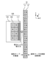
- 1 is a cross-sectional view schematically showing the configuration of a magnetic tape fixing device for an elevator according to Embodiment 1.
- FIG. 1 is a cross-sectional view schematically showing the overall configuration of an elevator equipped with a magnetic tape fixing device according to a first embodiment.
- FIG. 3 is a cross-sectional view schematically showing the configuration of another example of the magnetic tape fixing device for an elevator according to the first embodiment.
- FIG. 3 is a diagram illustrating an example of a magnetic path in the elevator magnetic tape fixing device according to the first embodiment.
- FIG. 7 is a cross-sectional view schematically showing the configuration of a magnetic tape in a magnetic tape fixing device for an elevator according to a second embodiment.
- Embodiment 1 of the present disclosure will be described with reference to FIGS. 1 to 5.
- 1 and 3 are cross-sectional views schematically showing the overall structure of an elevator equipped with a magnetic tape fixing device.
- FIG. 2 is a sectional view schematically showing the structure of an elevator magnetic tape fixing device.
- FIG. 4 is a sectional view schematically showing the structure of another example of the magnetic tape fixing device for an elevator.
- FIG. 5 is a diagram illustrating an example of a magnetic path in an elevator magnetic tape fixing device.
- the magnetic tape fixing device is installed in an elevator.
- a car 2 is installed in a hoistway 1 of an elevator.
- the car 2 moves up and down within the hoistway 1 while being guided by guide rails (not shown).
- One end of a main rope 4 is connected to the upper end of the car 2.
- the other end of the main rope 4 is connected to the upper end of the counterweight 3.
- the counterweight 3 is installed in the hoistway 1 so as to be movable up and down.
- the middle part of the main rope 4 is wrapped around a sheave of a hoist 5 installed at the top of the hoistway 1.
- the intermediate portion of the main rope 4 is also wrapped around a deflection sheave 9 provided adjacent to the sheave at the top of the hoistway.
- the car 2 and the counterweight 3 are suspended by the main rope 4 in the hoistway in a manner that they can be raised and lowered in opposite directions.
- the elevator is a so-called traction type elevator.
- the elevator according to this embodiment is not limited to a traction type, but may be a drum type, a hydraulic type, or the like.
- the hoist 5 rotates the sheave.
- the main rope 4 moves due to the frictional force between the main rope 4 and the sheave.
- the car 2 and the counterweight 3 suspended from the main rope 4 move up and down in opposite directions within the hoistway.
- a landing 6 is provided on each floor where the car 2 can stop.
- the landing 6 is a place where elevator users get on and off the car 2.
- a door 7 is provided at the landing 6 on each floor.
- the door 7 on the floor where the car 2 is not stopped is closed.
- the car 2 is also provided with a door (not shown). While the car 2 is running, the door of the car 2 is closed.
- the door of the car 2 is closed.
- the elevator includes a magnetic tape 10 and a reading device 30.
- the magnetic tape 10 and the reading device 30 are used to detect the position of the car 2 in the hoistway 1.
- the magnetic tape 10 is suspended within the hoistway 1. That is, the magnetic tape 10 is disposed within the hoistway 1 along the direction in which the car 2 moves up and down (hereinafter also simply referred to as the "up and down direction").
- the upper end side of the magnetic tape 10 is fixed to the inner wall at the top of the hoistway 1 by a fixing metal fitting 21.
- the lower end side of the magnetic tape 10 is fixed to a pit at the bottom of the hoistway 1 via a tension mechanism 22.
- the tension mechanism 22 includes, for example, an elastic body such as a tension spring or a weight.
- the pulling mechanism 22 uses an elastic body or a weight to apply a force to the magnetic tape 10 that pulls the lower end of the magnetic tape 10 downward. Thereby, the magnetic tape 10 can be kept in a tensioned state without sagging.
- the magnetic tape 10 has a back plate 11 and a hard magnetic material 12.
- the back plate 11 is made of stainless steel, for example.
- the hard magnetic material 12 is fixed to one side of the back plate 11.
- the hard magnetic body 12 is a permanent magnet and has a north pole and a south pole.
- the magnetic tape 10 includes a hard magnetic material 12 and has a structure in which a plurality of magnets (a pair of north and south poles) are arranged along the vertical direction.
- the arrangement of magnetic poles along the vertical direction on the magnetic tape 10 is a preset first arrangement. In this way, magnetic poles are formed on the magnetic tape 10 in the first arrangement set in advance along the vertical direction.
- a control panel 8 is installed at the top of the hoistway 1.
- the control panel 8 controls the overall operation of the elevator, including the raising and lowering of the car 2 and the like.
- the control circuit of the control panel 8 includes, for example, a processor and a memory (not shown).
- the control panel 8 controls the elevator by executing preset processing by a processor executing a program stored in a memory.
- a processor executes a program stored in a memory, and the hardware and software of the control panel 8 cooperate to realize the functions provided in the control panel 8.
- a processor is also referred to as a CPU (Central Processing Unit), central processing unit, processing unit, arithmetic unit, microprocessor, microcomputer, or DSP.
- Examples of the memory include nonvolatile or volatile semiconductor memories such as RAM, ROM, flash memory, EPROM, and EEPROM, magnetic disks, flexible disks, optical disks, compact disks, minidisks, and DVDs.
- control circuit of the control panel 8 may be formed as dedicated hardware, for example.
- a part of the control circuit of the control panel 8 may be formed as dedicated hardware, and the control circuit may be equipped with a processor and a memory.
- Control circuits that are partially formed as dedicated hardware include, for example, single circuits, composite circuits, programmed processors, parallel programmed processors, ASICs, FPGAs, or combinations thereof. .
- the car 2 is provided with a reading device 30.
- the reading device 30 has a magnetic sensor (not shown) that reads the arrangement of magnetic poles on the magnetic tape 10.
- the detection result by the reading device 30 is input to the control panel 8.
- the control panel 8 identifies the current position of the car 2 based on the magnetic pole arrangement of the magnetic tape 10 read by the reader 30.
- the length of the hoistway 1 is finite, and the length of the magnetic tape 10 is also finite.
- the magnetic pole array of the magnetic tape 10, that is, the first array described above, is set so that the same magnetic pole array pattern does not appear within this finite length range.
- Such a magnetic pole arrangement is, for example, an arrangement obtained by Manchester encoding a pseudorandom code such as an M sequence consisting of binary values of 0 and 1, with 0 as one of the north and south poles and 1 as the north pole. and the other of the S poles.
- the control panel 8 can specify the absolute position of the car 2 from the magnetic pole arrangement pattern of the magnetic tape 10 read by the reading device 30.
- the control panel 8 controls the operation of the hoist 5 and the like, and controls the raising and lowering of the car 2 according to the specified absolute position of the car 2.
- a tape threading section 31 is formed in the reading device 30.
- the tape passage portion 31 is a groove, a through hole, or the like formed in the reading device 30.
- the middle portion of the magnetic tape 10 is passed through a tape threading section 31 of a reading device 30.
- the magnetic sensor of the reading device 30 is arranged on the hard magnetic material 12 side of the magnetic tape 10 passed through the tape threading section 31 of the reading device 30 .
- the reading device 30 reads the magnetic pole arrangement of the magnetic tape 10 from the hard magnetic material 12 side of the magnetic tape 10 .
- the hard magnetic material 12 side of the magnetic tape 10 will also be referred to as the "reading side.” In this way, the magnetic tape 10 is read by the reading device 30 from the preset reading side to read the magnetic pole arrangement of the hard magnetic material 12 .
- the elevator includes a fixing device 100.
- the fixing device 100 is for fixing the intermediate portion of the magnetic tape 10 suspended in the hoistway 1.
- One or more fixing devices 100 are provided in the hoistway 1 . In the configuration example shown in FIG. 1, two fixing devices 100 are installed in the hoistway 1.
- the fixing device 100 includes a base portion 101 and a magnet portion 102.
- the fixing device 100 is arranged on the back plate 11 side of the magnetic tape 10 in the hoistway 1 .
- the back plate 11 side of the magnetic tape 10 is the opposite side to the reading side described above. Therefore, the base portion 101 (and the magnet portion 102) included in the fixing device 100 is arranged on the opposite side of the hoistway 1 from the reading side of the magnetic tape 10.
- the base portion 101 is fixed to the wall surface of the hoistway 1.
- a magnet portion 102 is provided on the base portion 101 .
- the magnet section 102 is a permanent magnet made of a hard magnetic material.
- the magnet portion 102 has magnetic poles formed in a second arrangement preset along the up-and-down direction of the car 2. Then, the fixing device 100 attracts the surface of the magnetic tape 10 on the back plate 11 side, that is, the surface of the magnetic tape 10 on the opposite side from the reading side, using the magnetic force generated from the magnet section 102.
- the fixing device 100 attracts and fixes the middle part of the magnetic tape 10 with magnetic force.
- the middle portion of the magnetic tape 10 is passed through the tape threading section 31 of the reading device 30.
- the portion of the magnetic tape 10 located at the position of the car 2 is pulled toward the reading side by the reading device 30. Therefore, when the car 2 comes close to the fixing device 100, the magnetic tape 10 is pulled toward the reading side against the magnetic force of the fixing device 100, so that the corresponding portion of the magnetic tape 10 is released from the restraint of the fixing device 100.
- FIG. 1 shows a state in which the car 2 is running on a lower floor.
- the magnetic tape 10 on the lower side of the hoistway 1 is pulled toward the reading side by the reader 30 of the car 2, and the restraint of the magnetic tape 10 by the fixing device 100 on the lower side of the hoistway 1 is released. ing. Therefore, the magnetic pole arrangement of the magnetic tape 10 can be read by the reading device 30 without interference between the fixing device 100 and the reading device 30.
- the magnetic tape 10 is restrained by the fixing device 100 located on the upper side of the hoistway 1, shaking of the magnetic tape 10 is suppressed.
- FIG. 3 shows a state in which the car 2 is traveling on an upper floor.
- the magnetic tape 10 is attracted and restrained.
- the magnetic tape 10 is pulled toward the reading side by the reader 30 of the car 2, and the restraint of the magnetic tape 10 by the fixing device 100 on the upper side of the hoistway 1 is released. Therefore, the magnetic pole arrangement of the magnetic tape 10 can be read by the reading device 30 without interference between the fixing device 100 and the reading device 30.
- the magnetic tape 10 is restrained by the fixing device 100 as the car 2 moves up and down, without requiring a movable mechanical structure. and release. Therefore, it is possible to suppress noise when the car 2 is running, and maintenance is also easy. Furthermore, since the fixing device 100 is fixed within the hoistway 1, the magnetic tape 10 can be placed sufficiently close to the inner wall of the hoistway 1, for example, and the fixing device 100 can be largely protruded into the hoistway 1. There's no need. Therefore, even if large shaking such as an earthquake occurs, the magnetic tape 10 can be prevented from being caught in the fixing device 100.
- the fixing device 100 may further include a protection plate 111.
- the protection plate 111 is provided to cover the surface of the magnet portion 102 that faces the magnetic tape 10 .
- the protection plate 111 is made of soft magnetic material or non-magnetic material.
- the magnetic force generated from the magnet portion 102 penetrates the protection plate 111 and acts on the magnetic tape 10 . Therefore, the fixing device 100 attracts the surface of the magnetic tape 10 on the back plate 11 side, that is, the surface on the opposite side from the reading side of the magnetic tape 10, by the magnetic force generated from the surface of the protection plate 111 facing the magnetic tape 10.
- damage to the magnet portion 102 and the back plate 11 when the fixing device 100 attracts the magnetic tape 10 can be suppressed.
- the second arrangement which is the magnetic pole arrangement of the magnet part 102 of the fixing device 100, may be the same as or different from the first arrangement, which is the magnetic pole arrangement of the magnetic tape 10 in the part facing the magnet part 102.
- the first arrangement which is the magnetic pole arrangement of the magnetic tape 10 in the portion of the fixing device 100 facing the magnet section 102
- the first arrangement of the magnetic tape 10 refers to the arrangement of magnetic poles appearing on the reading side of the magnetic tape 10.
- the second arrangement of the fixing device 100 refers to the arrangement of magnetic poles appearing on the magnetic tape 10 side of the fixing device 100.
- FIG. 2 shows an example in which the second arrangement of the fixing device 100 is the same as the first arrangement of the magnetic tape 10.
- the first arrangement of the magnetic tape 10 is set so that the same magnetic pole arrangement pattern does not exist in the vertical direction. Therefore, in order to make the second arrangement of the fixing devices 100 and the first arrangement of the magnetic tapes 10 the same, the second arrangement of the fixing devices 100 must be made different depending on the position of the fixing devices 100 in the vertical direction. must not. In particular, considering the possibility that the position of the fixing device 100 may need to be adjusted at the elevator installation site, it is difficult to set the second arrangement of the fixing device 100 in advance when the fixing device 100 is shipped from the factory. Therefore, it is necessary to read the first arrangement of the magnetic tape 10 corresponding to the position of the fixing device 100 and set the second arrangement of the fixing device 100 at the elevator installation site.
- the second arrangement of the fixing device 100 may be different from the first arrangement of the magnetic tape 10.
- FIG. 4 shows an example in which the second arrangement of the fixing device 100 is different from the first arrangement of the magnetic tape 10.
- the same magnetic poles of the fixing device 100 and the magnetic tape 10 may face each other in some parts. If the same magnetic poles face each other in a portion, the magnetic poles will repel each other, and there is a possibility that the force of attraction of the magnetic tape 10 by the fixing device 100 will be weakened.
- the protection plate 111 is preferably made of a soft magnetic material.
- FIG. 5 shows an example in which a protective plate 111 made of soft magnetic material is provided and the second arrangement is such that N poles and S poles are alternately arranged in the vertical direction.
- a magnetic path from the magnet portion 102 forms a closed circuit passing through a protection plate 111 made of a soft magnetic material. Therefore, the repulsive force generated between the magnet portion 102 of the fixing device 100 and the hard magnetic material 12 of the magnetic tape 10 can be reduced, and a decrease in the force with which the fixing device 100 attracts the magnetic tape 10 can be suppressed.
- the number, size, second arrangement, etc. of the magnet portions 102 of the fixing device 100 can be determined by estimating the adsorption force required to appropriately restrain the middle portion of the magnetic tape 10 by the fixing device 100.
- the adsorption force required to appropriately restrain the intermediate portion of the magnetic tape 10 by the fixing device 100 changes depending on conditions such as the tension applied to the magnetic tape 10 and the vibrations generated in the magnetic tape 10.
- Conditions related to the tension, vibration, etc. of the magnetic tape 10 include, for example, the following items.
- the weight of the magnetic tape 10 The temperature characteristics of the magnetic tape 10 -
- the position of the fixing device 100 in the hoistway 1 The position of the car 2 (the position of the car 2 lifting range) - If the tension mechanism 22 has an elastic body, the shape (length) of the elastic body - If the tension mechanism 22 has an elastic body, the temperature characteristics of the elastic body - If the tension mechanism 22 has a weight, the weight of the weight - Resonance between the magnetic tape 10 and the building in which the elevator is installed - Magnetic tape due to earthquakes Vibration of magnetic tape 10 due to wind Vibration of magnetic tape 10 due to lifting and lowering of car 2
- the base portion 101 of the fixing device 100 may be made of a non-magnetic material or a soft magnetic material.
- the base part 101 By making the base part 101 a soft magnetic material, the magnetic path from the magnet part 102 can be made to pass through the base part 101 which is a soft magnetic material, and it is possible to increase the magnetic flux density. Therefore, the force with which the fixing device 100 attracts the magnetic tape 10 can be improved.
- the magnet portion 102 of the fixing device 100 may be an electromagnet instead of a permanent magnet.
- the control panel 8 controls energization to the magnet section 102, which is an electromagnet.
- the control panel 8 stops energizing the magnet portion 102 when the car 2 approaches the fixing device 100, and starts energizing the magnet portion 102 when the car 2 passes the fixing device 100.
- the magnetic tape 10 can be smoothly attracted and released by the fixing device 100.
- the polarity and second arrangement of the magnet section 102 can be changed. Thereby, the magnetic pole arrangement and attractive force of the magnet section 102 can be easily set in accordance with the magnetic pole arrangement (first arrangement) of the magnetic tape 10.
- FIG. 6 is a sectional view schematically showing the configuration of a magnetic tape in an elevator magnetic tape fixing device.
- the magnetic tape 10 has a soft magnetic material 13 instead of the hard magnetic material 12 in the configuration of the first embodiment described above.
- the magnetic tape fixing device for an elevator according to the second embodiment will be described below, focusing on the differences from the first embodiment.
- the configuration whose description is omitted is basically the same as that of the first embodiment.
- structures similar to or corresponding to those of the first embodiment will be described with the same reference numerals used in the description of the first embodiment.
- the magnetic tape 10 includes a back plate 11 and a soft magnetic material 13.
- the back plate 11 is made of stainless steel, for example, as in the first embodiment.
- the soft magnetic material 13 is fixed to the above-mentioned reading side surface of the back plate 11.
- the soft magnetic bodies 13 are not arranged continuously from the upper end to the lower end along the vertical direction, but a gap 14 in which the soft magnetic bodies 13 do not exist is formed on the reading side surface of the back plate 11. There is.
- the arrangement of the soft magnetic bodies 13 and the voids 14 along the vertical direction of the magnetic tape 10 is the first arrangement described above. In this way, the soft magnetic bodies 13 are arranged on the magnetic tape 10 in the first arrangement set in advance along the vertical direction.
- the length of the hoistway 1 is finite, and the length of the magnetic tape 10 is also finite.
- the magnetic pole arrangement of the soft magnetic material 13 of the magnetic tape 10, that is, the above-mentioned first arrangement, is set so that the same arrangement pattern does not appear within this finite length range.
- Such an array is, for example, an array obtained by Manchester encoding a pseudo-random code such as an M sequence consisting of binary values of 0 and 1, in which 0 is placed in one of the soft magnetic material 13 and the air gap 14, and 1 is placed in one of the soft magnetic body 13 and the air gap 14. It can be set by corresponding to the other of the soft magnetic body 13 and the gap 14, respectively.
- the reading device 30 is equipped with a sensor (not shown) that can detect the presence or absence of the soft magnetic material 13 on the magnetic tape 10.
- the reading device 30 can read the arrangement of the soft magnetic material 13 and the gap 14 of the magnetic tape 10.
- the detection result by the reading device 30 is input to the control panel 8.
- the control panel 8 specifies the current absolute position of the car 2 based on the arrangement of the soft magnetic material 13 and the gap 14 of the magnetic tape 10 read by the reading device 30. Then, the control panel 8 controls the operation of the hoist 5 and the like, and controls the raising and lowering operation of the car 2 according to the specified absolute position of the car 2.
- the configuration of the fixing device 100 in this embodiment is the same as that in the first embodiment. That is, the fixing device 100 is for fixing the intermediate portion of the magnetic tape 10 suspended within the hoistway 1.
- One or more fixing devices 100 are provided in the hoistway 1 .
- the fixing device 100 includes a base portion 101 and a magnet portion 102.
- the fixing device 100 is arranged on the back plate 11 side of the magnetic tape 10 in the hoistway 1 .
- the base portion 101 is fixed to the wall surface of the hoistway 1.
- the base portion 101 is made of soft magnetic material or non-magnetic material.
- a magnet portion 102 is provided on the base portion 101 .
- the magnet section 102 is a permanent magnet or an electromagnet made of a hard magnetic material.
- the magnet portion 102 has magnetic poles formed in a second arrangement preset along the up-and-down direction of the car 2.
- the soft magnetic material 13 of the magnetic tape 10 is attracted by the magnetic force generated from the magnet section 102. Therefore, the fixing device 100 can attract the surface of the magnetic tape 10 on the back plate 11 side, that is, the surface of the magnetic tape 10 on the opposite side from the reading side, using the magnetic force generated from the magnet section 102.
- the second arrangement which is the magnetic pole arrangement of the magnet part 102 of the fixing device 100, may be the same as or different from the first arrangement, which is the magnetic pole arrangement of the magnetic tape 10 in the part facing the magnet part 102. Good too. Since the soft magnetic material 13 of the magnetic tape 10 does not have fixed magnetic poles, the fixing device 100 cannot attract the magnetic tape 10 no matter what the magnetic pole arrangement (second arrangement) of the magnet section 102 is. can be restrained.
- the magnetic tape fixing device for an elevator configured as described above can also achieve the same effects as in the first embodiment. That is, by attracting and restraining the middle portion of the magnetic tape 10 using magnetic force, vibrations and the like of the magnetic tape 10 can be suppressed. At this time, the magnetic tape 10 is restrained and released by the fixing device 100 as the car 2 moves up and down, without requiring a movable mechanical structure. Therefore, it is possible to suppress noise when the car 2 is running, and maintenance is also easy. Further, there is no need for the fixing device 100 to protrude significantly into the hoistway 1, and it is possible to suppress the magnetic tape 10 from being caught on the fixing device 100.
- the fixing device 100 may further include a protection plate 111.
- the protection plate 111 is provided to cover the surface of the magnet portion 102 that faces the magnetic tape 10 .
- the protection plate 111 is made of soft magnetic material or non-magnetic material.
- the magnetic force generated from the magnet portion 102 penetrates the protection plate 111 and acts on the magnetic tape 10 . Therefore, the fixing device 100 attracts the surface of the magnetic tape 10 on the back plate 11 side, that is, the surface on the opposite side from the reading side of the magnetic tape 10, by the magnetic force generated from the surface of the protection plate 111 facing the magnetic tape 10.
- damage to the magnet portion 102 and the back plate 11 when the fixing device 100 attracts the magnetic tape 10 can be suppressed.
- the present disclosure can be used in a magnetic tape fixing device that fixes the middle part of a magnetic tape suspended in an elevator hoistway.
Landscapes
- Engineering & Computer Science (AREA)
- Automation & Control Theory (AREA)
- Computer Networks & Wireless Communication (AREA)
- Indicating And Signalling Devices For Elevators (AREA)
- Elevator Control (AREA)
- Lift-Guide Devices, And Elevator Ropes And Cables (AREA)
- Cage And Drive Apparatuses For Elevators (AREA)
Priority Applications (3)
| Application Number | Priority Date | Filing Date | Title |
|---|---|---|---|
| PCT/JP2022/014142 WO2023181300A1 (ja) | 2022-03-24 | 2022-03-24 | エレベータの磁気テープ固定装置 |
| JP2024509610A JP7574966B2 (ja) | 2022-03-24 | 2022-03-24 | エレベータの磁気テープ固定装置 |
| CN202280093380.0A CN118973935A (zh) | 2022-03-24 | 2022-03-24 | 电梯的磁带固定装置 |
Applications Claiming Priority (1)
| Application Number | Priority Date | Filing Date | Title |
|---|---|---|---|
| PCT/JP2022/014142 WO2023181300A1 (ja) | 2022-03-24 | 2022-03-24 | エレベータの磁気テープ固定装置 |
Publications (1)
| Publication Number | Publication Date |
|---|---|
| WO2023181300A1 true WO2023181300A1 (ja) | 2023-09-28 |
Family
ID=88100707
Family Applications (1)
| Application Number | Title | Priority Date | Filing Date |
|---|---|---|---|
| PCT/JP2022/014142 Ceased WO2023181300A1 (ja) | 2022-03-24 | 2022-03-24 | エレベータの磁気テープ固定装置 |
Country Status (3)
| Country | Link |
|---|---|
| JP (1) | JP7574966B2 (https=) |
| CN (1) | CN118973935A (https=) |
| WO (1) | WO2023181300A1 (https=) |
Cited By (1)
| Publication number | Priority date | Publication date | Assignee | Title |
|---|---|---|---|---|
| DE102025154763A1 (de) | 2025-12-22 | 2026-02-26 | Tk Elevator Innovation And Operations Gmbh | Codebandanordnung und Aufzugsanlage mit einer solchen |
Families Citing this family (1)
| Publication number | Priority date | Publication date | Assignee | Title |
|---|---|---|---|---|
| JP7677510B1 (ja) | 2024-07-01 | 2025-05-15 | 三菱電機ビルソリューションズ株式会社 | エレベーターシステム |
Citations (6)
| Publication number | Priority date | Publication date | Assignee | Title |
|---|---|---|---|---|
| JP2015113180A (ja) * | 2013-12-09 | 2015-06-22 | フジテック株式会社 | エレベータのかご位置検出装置の調整方法 |
| JP2019077546A (ja) * | 2017-10-26 | 2019-05-23 | フジテック株式会社 | エレベータ |
| JP2019081647A (ja) * | 2017-10-31 | 2019-05-30 | フジテック株式会社 | ダブルデッキエレベータ |
| US20190367323A1 (en) * | 2016-09-30 | 2019-12-05 | Inventio Ag | Vibration stabilizer for an information carrier |
| WO2020115901A1 (ja) * | 2018-12-07 | 2020-06-11 | 株式会社日立製作所 | エレベーター装置 |
| US20210078826A1 (en) * | 2019-09-12 | 2021-03-18 | Thyssenkrupp Elevator Corporation | Magnetic tape stabilizing systems |
-
2022
- 2022-03-24 CN CN202280093380.0A patent/CN118973935A/zh active Pending
- 2022-03-24 WO PCT/JP2022/014142 patent/WO2023181300A1/ja not_active Ceased
- 2022-03-24 JP JP2024509610A patent/JP7574966B2/ja active Active
Patent Citations (6)
| Publication number | Priority date | Publication date | Assignee | Title |
|---|---|---|---|---|
| JP2015113180A (ja) * | 2013-12-09 | 2015-06-22 | フジテック株式会社 | エレベータのかご位置検出装置の調整方法 |
| US20190367323A1 (en) * | 2016-09-30 | 2019-12-05 | Inventio Ag | Vibration stabilizer for an information carrier |
| JP2019077546A (ja) * | 2017-10-26 | 2019-05-23 | フジテック株式会社 | エレベータ |
| JP2019081647A (ja) * | 2017-10-31 | 2019-05-30 | フジテック株式会社 | ダブルデッキエレベータ |
| WO2020115901A1 (ja) * | 2018-12-07 | 2020-06-11 | 株式会社日立製作所 | エレベーター装置 |
| US20210078826A1 (en) * | 2019-09-12 | 2021-03-18 | Thyssenkrupp Elevator Corporation | Magnetic tape stabilizing systems |
Cited By (1)
| Publication number | Priority date | Publication date | Assignee | Title |
|---|---|---|---|---|
| DE102025154763A1 (de) | 2025-12-22 | 2026-02-26 | Tk Elevator Innovation And Operations Gmbh | Codebandanordnung und Aufzugsanlage mit einer solchen |
Also Published As
| Publication number | Publication date |
|---|---|
| JPWO2023181300A1 (https=) | 2023-09-28 |
| JP7574966B2 (ja) | 2024-10-29 |
| CN118973935A (zh) | 2024-11-15 |
Similar Documents
| Publication | Publication Date | Title |
|---|---|---|
| WO2023181300A1 (ja) | エレベータの磁気テープ固定装置 | |
| CN104781174B (zh) | 电梯制动器 | |
| CN105636896A (zh) | 用于电梯的紧急安全致动器 | |
| US11649139B2 (en) | Electronic safety actuator assembly for elevator system | |
| US20190233251A1 (en) | Method and an elevator control unit for controlling a doorstep gap of an elevator and an elevator | |
| EP3929131A1 (en) | Electrionic actuation module for elevator safety brake system | |
| JP5277723B2 (ja) | エレベーター制御ケーブル制振装置 | |
| JP2006188316A (ja) | エレベータ | |
| KR20000013168A (ko) | 엘리베이터 문의 닫힘력 부과장치 및 그 제어방법 | |
| JP2881622B2 (ja) | 磁気浮上式引き戸の開閉装置 | |
| JP2018111551A (ja) | 巻上機及びエレベーター | |
| JP2011093644A (ja) | エレベータ装置 | |
| CN113336118A (zh) | 带彼此接合的电磁体组件和永磁体组件的电梯制动器组件 | |
| ES3049800T3 (en) | Safety brake system | |
| CN111717829B (zh) | 静音电磁制动器 | |
| JP7306471B2 (ja) | エレベーターの索条体の制振装置 | |
| JPH1111823A (ja) | エレベータの安全装置 | |
| JPH03244777A (ja) | 磁気浮上自走式懸垂引き戸 | |
| JPH01288588A (ja) | エレベータ移動ケーブルの振れ防止装置 | |
| CN211110558U (zh) | 新型无绳电梯 | |
| CN109019260B (zh) | 电梯防晃动装置 | |
| CN110654954B (zh) | 电子安全致动器电磁导引 | |
| JP6249286B2 (ja) | エレベータのかご揺れ検出装置 | |
| HK40012640A (en) | Method and an elevator control unit for controlling a doorstep gap of an elevator and an elevator | |
| JP2020193065A (ja) | エレベータ |
Legal Events
| Date | Code | Title | Description |
|---|---|---|---|
| 121 | Ep: the epo has been informed by wipo that ep was designated in this application |
Ref document number: 22933440 Country of ref document: EP Kind code of ref document: A1 |
|
| ENP | Entry into the national phase |
Ref document number: 2024509610 Country of ref document: JP Kind code of ref document: A |
|
| WWE | Wipo information: entry into national phase |
Ref document number: 202280093380.0 Country of ref document: CN |
|
| NENP | Non-entry into the national phase |
Ref country code: DE |
|
| 122 | Ep: pct application non-entry in european phase |
Ref document number: 22933440 Country of ref document: EP Kind code of ref document: A1 |