WO2023181171A1 - インクジェット記録装置、及びインクジェット記録システム - Google Patents
インクジェット記録装置、及びインクジェット記録システム Download PDFInfo
- Publication number
- WO2023181171A1 WO2023181171A1 PCT/JP2022/013508 JP2022013508W WO2023181171A1 WO 2023181171 A1 WO2023181171 A1 WO 2023181171A1 JP 2022013508 W JP2022013508 W JP 2022013508W WO 2023181171 A1 WO2023181171 A1 WO 2023181171A1
- Authority
- WO
- WIPO (PCT)
- Prior art keywords
- ink
- inkjet recording
- print head
- main body
- head
- Prior art date
- Legal status (The legal status is an assumption and is not a legal conclusion. Google has not performed a legal analysis and makes no representation as to the accuracy of the status listed.)
- Ceased
Links
Images










Classifications
-
- B—PERFORMING OPERATIONS; TRANSPORTING
- B41—PRINTING; LINING MACHINES; TYPEWRITERS; STAMPS
- B41J—TYPEWRITERS; SELECTIVE PRINTING MECHANISMS, i.e. MECHANISMS PRINTING OTHERWISE THAN FROM A FORME; CORRECTION OF TYPOGRAPHICAL ERRORS
- B41J2/00—Typewriters or selective printing mechanisms characterised by the printing or marking process for which they are designed
- B41J2/005—Typewriters or selective printing mechanisms characterised by the printing or marking process for which they are designed characterised by bringing liquid or particles selectively into contact with a printing material
- B41J2/01—Ink jet
- B41J2/07—Ink jet characterised by jet control
- B41J2/075—Ink jet characterised by jet control for many-valued deflection
- B41J2/08—Ink jet characterised by jet control for many-valued deflection charge-control type
-
- B—PERFORMING OPERATIONS; TRANSPORTING
- B41—PRINTING; LINING MACHINES; TYPEWRITERS; STAMPS
- B41J—TYPEWRITERS; SELECTIVE PRINTING MECHANISMS, i.e. MECHANISMS PRINTING OTHERWISE THAN FROM A FORME; CORRECTION OF TYPOGRAPHICAL ERRORS
- B41J2/00—Typewriters or selective printing mechanisms characterised by the printing or marking process for which they are designed
- B41J2/005—Typewriters or selective printing mechanisms characterised by the printing or marking process for which they are designed characterised by bringing liquid or particles selectively into contact with a printing material
- B41J2/01—Ink jet
- B41J2/07—Ink jet characterised by jet control
- B41J2/075—Ink jet characterised by jet control for many-valued deflection
- B41J2/08—Ink jet characterised by jet control for many-valued deflection charge-control type
- B41J2/085—Charge means, e.g. electrodes
-
- B—PERFORMING OPERATIONS; TRANSPORTING
- B41—PRINTING; LINING MACHINES; TYPEWRITERS; STAMPS
- B41J—TYPEWRITERS; SELECTIVE PRINTING MECHANISMS, i.e. MECHANISMS PRINTING OTHERWISE THAN FROM A FORME; CORRECTION OF TYPOGRAPHICAL ERRORS
- B41J2/00—Typewriters or selective printing mechanisms characterised by the printing or marking process for which they are designed
- B41J2/005—Typewriters or selective printing mechanisms characterised by the printing or marking process for which they are designed characterised by bringing liquid or particles selectively into contact with a printing material
- B41J2/01—Ink jet
- B41J2/07—Ink jet characterised by jet control
- B41J2/125—Sensors, e.g. deflection sensors
-
- B—PERFORMING OPERATIONS; TRANSPORTING
- B41—PRINTING; LINING MACHINES; TYPEWRITERS; STAMPS
- B41J—TYPEWRITERS; SELECTIVE PRINTING MECHANISMS, i.e. MECHANISMS PRINTING OTHERWISE THAN FROM A FORME; CORRECTION OF TYPOGRAPHICAL ERRORS
- B41J2/00—Typewriters or selective printing mechanisms characterised by the printing or marking process for which they are designed
- B41J2/005—Typewriters or selective printing mechanisms characterised by the printing or marking process for which they are designed characterised by bringing liquid or particles selectively into contact with a printing material
- B41J2/01—Ink jet
- B41J2/135—Nozzles
- B41J2/165—Prevention or detection of nozzle clogging, e.g. cleaning, capping or moistening for nozzles
- B41J2/16517—Cleaning of print head nozzles
- B41J2/16552—Cleaning of print head nozzles using cleaning fluids
-
- B—PERFORMING OPERATIONS; TRANSPORTING
- B41—PRINTING; LINING MACHINES; TYPEWRITERS; STAMPS
- B41J—TYPEWRITERS; SELECTIVE PRINTING MECHANISMS, i.e. MECHANISMS PRINTING OTHERWISE THAN FROM A FORME; CORRECTION OF TYPOGRAPHICAL ERRORS
- B41J2/00—Typewriters or selective printing mechanisms characterised by the printing or marking process for which they are designed
- B41J2/005—Typewriters or selective printing mechanisms characterised by the printing or marking process for which they are designed characterised by bringing liquid or particles selectively into contact with a printing material
- B41J2/01—Ink jet
- B41J2/17—Ink jet characterised by ink handling
- B41J2/1707—Conditioning of the inside of ink supply circuits, e.g. flushing during start-up or shut-down
-
- B—PERFORMING OPERATIONS; TRANSPORTING
- B41—PRINTING; LINING MACHINES; TYPEWRITERS; STAMPS
- B41J—TYPEWRITERS; SELECTIVE PRINTING MECHANISMS, i.e. MECHANISMS PRINTING OTHERWISE THAN FROM A FORME; CORRECTION OF TYPOGRAPHICAL ERRORS
- B41J2/00—Typewriters or selective printing mechanisms characterised by the printing or marking process for which they are designed
- B41J2/005—Typewriters or selective printing mechanisms characterised by the printing or marking process for which they are designed characterised by bringing liquid or particles selectively into contact with a printing material
- B41J2/01—Ink jet
- B41J2/17—Ink jet characterised by ink handling
- B41J2/175—Ink supply systems ; Circuit parts therefor
-
- B—PERFORMING OPERATIONS; TRANSPORTING
- B41—PRINTING; LINING MACHINES; TYPEWRITERS; STAMPS
- B41J—TYPEWRITERS; SELECTIVE PRINTING MECHANISMS, i.e. MECHANISMS PRINTING OTHERWISE THAN FROM A FORME; CORRECTION OF TYPOGRAPHICAL ERRORS
- B41J2/00—Typewriters or selective printing mechanisms characterised by the printing or marking process for which they are designed
- B41J2/005—Typewriters or selective printing mechanisms characterised by the printing or marking process for which they are designed characterised by bringing liquid or particles selectively into contact with a printing material
- B41J2/01—Ink jet
- B41J2/17—Ink jet characterised by ink handling
- B41J2/18—Ink recirculation systems
-
- B—PERFORMING OPERATIONS; TRANSPORTING
- B41—PRINTING; LINING MACHINES; TYPEWRITERS; STAMPS
- B41J—TYPEWRITERS; SELECTIVE PRINTING MECHANISMS, i.e. MECHANISMS PRINTING OTHERWISE THAN FROM A FORME; CORRECTION OF TYPOGRAPHICAL ERRORS
- B41J2/00—Typewriters or selective printing mechanisms characterised by the printing or marking process for which they are designed
- B41J2/005—Typewriters or selective printing mechanisms characterised by the printing or marking process for which they are designed characterised by bringing liquid or particles selectively into contact with a printing material
- B41J2/01—Ink jet
- B41J2/17—Ink jet characterised by ink handling
- B41J2/18—Ink recirculation systems
- B41J2/185—Ink-collectors; Ink-catchers
-
- B—PERFORMING OPERATIONS; TRANSPORTING
- B41—PRINTING; LINING MACHINES; TYPEWRITERS; STAMPS
- B41J—TYPEWRITERS; SELECTIVE PRINTING MECHANISMS, i.e. MECHANISMS PRINTING OTHERWISE THAN FROM A FORME; CORRECTION OF TYPOGRAPHICAL ERRORS
- B41J2/00—Typewriters or selective printing mechanisms characterised by the printing or marking process for which they are designed
- B41J2/005—Typewriters or selective printing mechanisms characterised by the printing or marking process for which they are designed characterised by bringing liquid or particles selectively into contact with a printing material
- B41J2/01—Ink jet
- B41J2/17—Ink jet characterised by ink handling
- B41J2/195—Ink jet characterised by ink handling for monitoring ink quality
-
- B—PERFORMING OPERATIONS; TRANSPORTING
- B41—PRINTING; LINING MACHINES; TYPEWRITERS; STAMPS
- B41J—TYPEWRITERS; SELECTIVE PRINTING MECHANISMS, i.e. MECHANISMS PRINTING OTHERWISE THAN FROM A FORME; CORRECTION OF TYPOGRAPHICAL ERRORS
- B41J29/00—Details of, or accessories for, typewriters or selective printing mechanisms not otherwise provided for
- B41J29/377—Cooling or ventilating arrangements
-
- B—PERFORMING OPERATIONS; TRANSPORTING
- B41—PRINTING; LINING MACHINES; TYPEWRITERS; STAMPS
- B41J—TYPEWRITERS; SELECTIVE PRINTING MECHANISMS, i.e. MECHANISMS PRINTING OTHERWISE THAN FROM A FORME; CORRECTION OF TYPOGRAPHICAL ERRORS
- B41J29/00—Details of, or accessories for, typewriters or selective printing mechanisms not otherwise provided for
- B41J29/38—Drives, motors, controls or automatic cut-off devices for the entire printing mechanism
-
- B—PERFORMING OPERATIONS; TRANSPORTING
- B41—PRINTING; LINING MACHINES; TYPEWRITERS; STAMPS
- B41J—TYPEWRITERS; SELECTIVE PRINTING MECHANISMS, i.e. MECHANISMS PRINTING OTHERWISE THAN FROM A FORME; CORRECTION OF TYPOGRAPHICAL ERRORS
- B41J29/00—Details of, or accessories for, typewriters or selective printing mechanisms not otherwise provided for
- B41J29/38—Drives, motors, controls or automatic cut-off devices for the entire printing mechanism
- B41J29/393—Devices for controlling or analysing the entire machine ; Controlling or analysing mechanical parameters involving printing of test patterns
-
- G—PHYSICS
- G06—COMPUTING OR CALCULATING; COUNTING
- G06F—ELECTRIC DIGITAL DATA PROCESSING
- G06F3/00—Input arrangements for transferring data to be processed into a form capable of being handled by the computer; Output arrangements for transferring data from processing unit to output unit, e.g. interface arrangements
- G06F3/12—Digital output to print unit, e.g. line printer, chain printer
- G06F3/1201—Dedicated interfaces to print systems
- G06F3/1202—Dedicated interfaces to print systems specifically adapted to achieve a particular effect
- G06F3/121—Facilitating exception or error detection and recovery, e.g. fault, media or consumables depleted
-
- G—PHYSICS
- G06—COMPUTING OR CALCULATING; COUNTING
- G06F—ELECTRIC DIGITAL DATA PROCESSING
- G06F3/00—Input arrangements for transferring data to be processed into a form capable of being handled by the computer; Output arrangements for transferring data from processing unit to output unit, e.g. interface arrangements
- G06F3/12—Digital output to print unit, e.g. line printer, chain printer
- G06F3/1201—Dedicated interfaces to print systems
- G06F3/1223—Dedicated interfaces to print systems specifically adapted to use a particular technique
- G06F3/1229—Printer resources management or printer maintenance, e.g. device status, power levels
-
- G—PHYSICS
- G06—COMPUTING OR CALCULATING; COUNTING
- G06F—ELECTRIC DIGITAL DATA PROCESSING
- G06F3/00—Input arrangements for transferring data to be processed into a form capable of being handled by the computer; Output arrangements for transferring data from processing unit to output unit, e.g. interface arrangements
- G06F3/12—Digital output to print unit, e.g. line printer, chain printer
- G06F3/1201—Dedicated interfaces to print systems
- G06F3/1278—Dedicated interfaces to print systems specifically adapted to adopt a particular infrastructure
- G06F3/1285—Remote printer device, e.g. being remote from client or server
- G06F3/1288—Remote printer device, e.g. being remote from client or server in client-server-printer device configuration
-
- G—PHYSICS
- G06—COMPUTING OR CALCULATING; COUNTING
- G06F—ELECTRIC DIGITAL DATA PROCESSING
- G06F3/00—Input arrangements for transferring data to be processed into a form capable of being handled by the computer; Output arrangements for transferring data from processing unit to output unit, e.g. interface arrangements
- G06F3/12—Digital output to print unit, e.g. line printer, chain printer
- G06F3/1201—Dedicated interfaces to print systems
- G06F3/1278—Dedicated interfaces to print systems specifically adapted to adopt a particular infrastructure
- G06F3/1292—Mobile client, e.g. wireless printing
-
- B—PERFORMING OPERATIONS; TRANSPORTING
- B41—PRINTING; LINING MACHINES; TYPEWRITERS; STAMPS
- B41J—TYPEWRITERS; SELECTIVE PRINTING MECHANISMS, i.e. MECHANISMS PRINTING OTHERWISE THAN FROM A FORME; CORRECTION OF TYPOGRAPHICAL ERRORS
- B41J2/00—Typewriters or selective printing mechanisms characterised by the printing or marking process for which they are designed
- B41J2/005—Typewriters or selective printing mechanisms characterised by the printing or marking process for which they are designed characterised by bringing liquid or particles selectively into contact with a printing material
- B41J2/01—Ink jet
- B41J2/17—Ink jet characterised by ink handling
- B41J2/18—Ink recirculation systems
- B41J2/185—Ink-collectors; Ink-catchers
- B41J2002/1853—Ink-collectors; Ink-catchers ink collectors for continuous Inkjet printers, e.g. gutters, mist suction means
Definitions
- the present invention relates to a continuous jet inkjet recording device and an inkjet recording system.
- Patent Document 1 describes an ink container that stores ink for printing on a printing target, a nozzle that is connected to the ink container and that ejects pressurized ink, and ink particles that are ejected from the nozzle.
- a charging electrode that charges the charging electrode; a charging signal generating unit that generates a charging signal that charges the charging electrode; a deflection electrode that deflects ink particles charged with the charging electrode; and a gutter that collects ink that is not used for printing; a control section that controls the overall operation; and a first charge detection means that detects the amount of charge caused by charging the ink particles between the charging electrode and the deflection electrode; and a first charge detection means that detects the amount of charge of the ink flowing in the gutter.
- An inkjet recording apparatus having a second charge detection means is disclosed.
- Patent Document 2 includes a print head that receives a supply of ink and performs printing, an ink container for accommodating the ink, and a solvent container for accommodating a solvent, and the ink in the ink container is supplied to the print head.
- the print head has a nozzle that ejects ink as ink particles, a charging electrode that charges the ink particles ejected from the nozzle in accordance with the content to be printed, and a print head that discharges the ink as ink particles.
- An inkjet recording system that includes a head cleaning unit that includes a cleaning nozzle that sprays solvent toward the cleaning tank, a recovery container that is installed at the bottom of the cleaning tank and that collects the solvent after cleaning, and a drive unit that supplies the solvent to the cleaning nozzle.
- Patent Document 2 discloses that during a period when a print head is installed, ink in an ink container is supplied to a nozzle at regular intervals, and ink particles ejected from the nozzle are collected by a gutter and returned to the ink container.
- An inkjet recording device that is controlled to collect ink is disclosed.
- Patent Document 1 describes the configuration and control method of an inkjet recording apparatus for detecting an abnormality (generally referred to as beam bending) in which ink particles ejected from a nozzle of a print head cannot be captured by a gutter. .
- beam bending an abnormality
- Such an abnormality (beam bending) may occur immediately after the nozzle starts ejecting ink (at the start of operation), and when an abnormality (beam bending) occurs, there is a risk of contaminating the area around the print head with ink. There is. Therefore, it is necessary to clean this contaminated ink.
- Patent Document 2 discloses that a solvent is discharged from a cleaning nozzle to a print head installed in a head cleaning unit to clean ink stains from the print head, and then air is discharged from an air nozzle to clean the print head.
- the structure and control method of an inkjet recording apparatus for drying attached solvent is described.
- Patent Document 2 With the print head attached to a head cleaning unit, ink is jetted from the nozzles of the print head periodically at intervals of about once every two to three days for maintenance management, and the ink is washed into the gutter.
- a cleaning process that collects and circulates the ink, problems such as ink sticking are reduced the next time it is used (at the start of operation).
- Operational information of such automatic ink circulation processing (such as whether an abnormality has occurred) can be confirmed from the operation screen of the inkjet recording apparatus.
- maintenance management of the print head is performed by an operator operating (pressing) a button arranged on the operation screen of the inkjet recording apparatus.
- a print head cleaning process may be required before each start of operation (before ink is ejected from the nozzles). In this case, workers must go to the location where the inkjet recording device is installed each time, but in large-scale factories where multiple inkjet recording devices are used, this becomes troublesome and requires a lot of work. It will cost you work time.
- An object of the present invention is to provide an inkjet recording device and an inkjet recording system that can remotely perform maintenance management such as print head cleaning processing.
- Another object of the present invention is to enable operation information to be checked remotely when automatic ink circulation processing is being carried out periodically, and to notify a worker to take corrective action if there is an abnormality.
- An object of the present invention is to provide an inkjet recording device and an inkjet recording system that can perform the following steps.
- the first feature of the present invention is A nozzle that ejects the supplied ink into particles, a charging electrode that charges the ink particles ejected from the nozzle, a deflection electrode that deflects the ink particles charged by the charging electrode, and collects unused ink that is not used for printing.
- a print head having a gutter; An ink supply path for supplying ink in the ink container to the print head, an ink recovery path for collecting ink not used for printing into the ink container, and a solvent supply path for supplying the solvent in the solvent container to the ink container.
- a body comprising channels and regulators for regulating the flow of ink and solvent in the respective channels; an adjustment section of the main body and a main body control section that controls the operation of the print head;
- An inkjet recording device comprising a head mounting part for mounting and storing a print head, and a head mounting unit having a print head detector for detecting that the print head is mounted,
- the main body control unit includes a transmission unit that transmits head attachment detection information indicating that the print head is attached to the head attachment unit based on a detection signal from the print head detector to an external control device connected via a network. It is equipped with the following.
- the second feature of the present invention is An inkjet recording system comprising an inkjet recording device, a server connected to the inkjet recording device, a network to which the server is connected, and an external control device connected to the network and controlling the inkjet recording device via the server,
- the inkjet recording device is A nozzle that ejects the supplied ink into particles, a charging electrode that charges the ink particles ejected from the nozzle, a deflection electrode that deflects the ink particles charged by the charging electrode, and collects unused ink that is not used for printing.
- a print head having a gutter;
- a main body including a flow rate adjusting section that adjusts the flow of ink and solvent in the respective paths; a main body control section that controls the flow rate adjustment section of the main body and the operation of the print head;
- a head mounting unit for mounting and accommodating a print head, and a head mounting unit having a print head detector for determining whether or not the print head is mounted,
- the external control device is
- a head attachment confirmation means is provided that can confirm that the print head is attached to the head attachment unit based on head attachment detection information transmitted from the main body control unit indicating that the print head is attached to the head attachment unit. It's where you are.
- the operation information can be checked remotely, and if there is an abnormality, the operator can be contacted to request corrective action.
- FIG. 1 is a configuration diagram showing an overall outline of an inkjet recording apparatus and an inkjet recording system according to a first embodiment of the present invention.
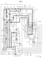
- 2 is a route configuration diagram showing the configuration of an ink supply route of the inkjet recording apparatus in FIG. 1.
- FIG. 2 is a block diagram showing the configuration of the inkjet recording apparatus in FIG. 1.
- FIG. 2 is a configuration diagram showing the configuration of the head mounted unit of FIG. 1 with a collection container removed.
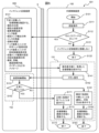
- FIG. 2 is a configuration diagram showing a state in which a collection container and a print head are installed in the head installation unit of FIG. 1; 2 is an explanatory diagram illustrating the flow of operations and monitoring in the inkjet recording system of FIG. 1.
- FIG. 1 is a configuration diagram showing an overall outline of an inkjet recording apparatus and an inkjet recording system according to a first embodiment of the present invention.
- 2 is a route configuration diagram showing the configuration of an ink supply route of the inkjet recording apparatus in FIG. 1.
- FIG. 2 is an explanatory diagram illustrating operations and a monitoring screen displayed on the external control device of FIG. 1.
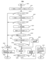
- FIG. FIG. 3 is a flowchart illustrating operation start processing in the print head.
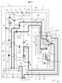
- FIG. 2 is a route configuration diagram illustrating the flow of liquids such as ink and solvent, and gases such as air and volatile gas (indicated by thick lines) when an operation start process is performed.
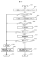
- FIG. 3 is a flowchart diagram illustrating operation stop processing in the print head.
- FIG. 2 is a path configuration diagram illustrating the flow of liquids such as ink and solvent, and gases such as air and volatile gas (indicated by thick lines) when an operation stop process is performed.
- FIG. 3 is a flowchart illustrating head cleaning processing in a print head.
- FIG. 3 is a path configuration diagram illustrating the flow of liquids such as ink and solvent, and gases such as air and volatile gas (indicated by thick lines) when a head cleaning process is performed.
- FIG. 6 is an explanatory diagram illustrating a state in which a collection container contains a large amount of cleaning liquid in the head mounted unit.
- FIG. 3 is a flowchart illustrating automatic ink circulation setting processing in the print head.
- FIG. 3 is a path configuration diagram illustrating the flow of ink, liquids such as solvents, and gases such as air and volatile gases (indicated by thick lines) when automatic ink circulation setting processing is performed. It is a block diagram which shows the outline of the whole inkjet recording device and inkjet recording system in the 2nd Embodiment of this invention.
- FIG. 19 is a block diagram which shows the outline of the whole inkjet recording device and inkjet recording system in the 3rd Embodiment of this invention. 19 is an explanatory diagram illustrating the flow of operations and monitoring in the inkjet recording system of FIG. 18.
- FIG. 19 is an explanatory diagram illustrating the flow of operations and monitoring in the inkjet recording system of FIG. 18.
- FIG. 1 is a perspective view showing how an inkjet recording apparatus according to a first embodiment of the present invention is used.
- an inkjet recording system 501 includes an inkjet recording device 600A or 600B, an IoT site server 9 connected to the inkjet recording device 600 by a cable 10, and an external control device that performs wireless communication with the IoT site server 9 via a network 14. 100.
- Inkjet recording devices 600A and 600B each include a main body 1, a print head 2 connected to the main body 1 by a cable (for print head) 5, and a head connected to the main body 1 by a cable (for head attachment unit) 6.
- a mounting unit 3 is provided.
- the head mounting unit 3 basically has the function of accommodating the print head, but may also have an additional function of cleaning the print head by spraying a cleaning liquid.
- the head mounting unit 3 described below has a configuration in which a function for cleaning the print head is added.
- the inkjet recording device 600A shows a state in which the print head 2 is installed on a production line. Further, the inkjet recording apparatus 600B is shown with the print head 2 removed from the production line and mounted on the head mounting unit 3. Note that the recovery container 4 attached to the lower part of the head mounting unit 3 is provided to contain the cleaning liquid after the print head is washed by the head mounting unit 3.
- the inkjet recording device 600A is installed, for example, on a production line in a factory where foods, drinks, etc. are produced, and the main body 1 is installed in a location where the space necessary for regular maintenance work can be secured.
- the print head 2 is fixed to a support fitting 13 installed near the belt conveyor 11, and is used to print on print objects 12A and 12B that are fed in the direction of arrow X on a production line such as the belt conveyor 11. are located close together.
- a protective cover 95 is attached to the print head 2 for the purpose of protecting the parts inside the print head 2.
- the printing object 12B is shown in a state where printing by the print head 2 has been completed and it is being conveyed on the belt conveyor 11.
- a main body 1 accommodates (holds) ink for printing, and controls a drive unit (pump and solenoid valve) inside the main body to supply ink via a cable (for print head) 5. Supplied to print head 2.
- a drive unit pump and solenoid valve
- the operation display section 8 is installed on the top surface of the main body 1, and here a touch input type display panel is used. By touching the operation display section 8, the operator can instruct the main body control section to start or stop the apparatus, or set the content to be printed on the printing object 12A. Further, in FIG. 1, reference number 94 in the print head 2 indicates a head base, and reference number 95 indicates a protective cover.
- the head mounting unit 3 is installed around the print head 2.
- the head mounting unit 3 in the inkjet recording apparatus 600A is fixed by combining a fixing jig 92 assembled to the belt conveyor 11 with a fitting part 93 assembled to the head mounting unit 3.
- the head mounting unit 3 includes a head mounting section 81A for mounting the print head 2 on the head mounting unit.
- the head mounting unit 3 has a start button 18 for starting the cleaning process for the print head 2, a stop button 19 for stopping the cleaning process for the print head 2, and a button for sending confirmation messages and alarms such as alarms and abnormalities. It also includes a display section 20 for the operator to recognize.
- the display unit 20 may allow the operator to recognize the operating state and the presence or absence of an abnormality by, for example, the presence or absence of light or a difference in color.
- the head mounting unit 3 is fixed near the belt conveyor 11, but the head mounting unit 3 can be freely replaced at a location convenient for the user.
- the length of the cable (for the head mounted unit) 6 connecting the main body 1 and the head mounted unit 3 is the same as or longer than the cable 5 that connects the main body 1 and the print head 2 of the inkjet recording apparatus 600. is preferable. This is to ensure flexibility in the arrangement of the head mounting unit.
- the main body 1 has a fixing part 91 for fixing the head mounting unit 3, and the head mounting unit 3 is fixed to the fixing part 91 by removing the head mounting unit 3 from the fixing jig (for conveyor) 92. It is also possible to use it as a replacement.
- the head mounting unit 3 can also be fixed to the main body 1 by combining the fitting part 93 with the fixing part 91 assembled to the main body 1.
- the head mounting unit 3 of the inkjet recording apparatus 600B is attached to the main body 1. By making the head mounting unit 3 fixable to the main body 1, the head mounting unit 3 can be installed even if there is no space for mounting the head mounting unit 3 near the belt conveyor 11 or the like.
- the print head 2 is mounted by inserting the print head 2 into the head mounting portion 81A of the head mounting unit 3 from the tip thereof.
- the solvent 69A (see FIG. 2) is supplied from the main body 1 via the cable (for the head mounting unit) 6. ), the print head 2 can be cleaned.
- the external control device 100 devices such as a personal computer 15, a smartphone 16, a tablet 17, etc. can be used.
- a "LAN (Local Area Network)”, “WAN (Wide Area Network)”, “Internet”, “Mobile phone line network”, or a combination of these networks can be used.
- the network 14 of this embodiment has a configuration in which the IoT field server 9 and the external control device 100 are connected using the Internet and a mobile phone network.
- FIG. 2 is a diagram showing the overall configuration of a path through which fluids such as ink and gas flow in the inkjet recording apparatus 600 in this embodiment.
- the electromagnetic valve that controls the flow of liquid such as ink and gas functions as a "flow rate adjustment section.”
- the main body 1 is equipped with a main ink container 31 that holds ink 68A for printing.
- the main ink container 31 is equipped with a liquid level sensor 31A that detects whether the ink 68A in the main ink container 31 has reached a reference liquid level that is an appropriate amount to be retained inside. There is.
- the main ink container 31 is connected to a path (for supply) 801 at the part immersed in the ink 68A, and a solenoid valve (for supply) 49 is installed in the middle of the path 801 to open and close the path.
- a path 801 is connected via a confluence path 901 to a pump (for supply) 34 installed in the path 802 and used for sucking and pumping the ink 68A.
- the output side of the pump (for supply) 34 is connected to a filter (for supply) 39 that removes foreign matter mixed in the ink 68A.
- the filter (for supply) 39 is connected to a pressure regulating valve 46 that adjusts the ink 68A pumped from the pump (for supply) 34 to an appropriate pressure for printing, and the pressure regulating valve 46 is supplied to the nozzle 21. It is connected to a pressure sensor 47 that measures the pressure of the ink 68A.
- a path 802 in which the pressure sensor 47 is arranged is connected to a path 803 passing through the cable (for print head) 5 via a branch path 921, and the path 803 is provided in the print head 2 and supplies it to the nozzle 8.
- It is connected to a heater 29 that heats the ink 68A.
- the heater 29 is connected to a switching valve 26 for controlling whether or not the ink 68A is supplied to the nozzle 21.
- the switching valve 26 is connected via a path 804 to a nozzle 21 having an ejection port 21A that ejects ink 68A.
- the switching valve 26 is a three-way solenoid valve, and an ink supply path 803 and a nozzle cleaning path 835 are connected to the switching valve 26, and the ink 68A and solvent 69A are supplied to the nozzle 21. Can be switched.
- a charging electrode 23 for adding a predetermined amount of charge to the ink particles 68B
- a deflection electrode 24 for deflecting the ink particles 68B used for printing
- a charging electrode 24 for deflecting the ink particles 68B used for printing.
- a gutter 25 is disposed to catch ink particles 68B that fly straight without being charged or deflected.
- the ink recovery path (811 to 812) of the inkjet recording apparatus 600 will be explained.
- the gutter 25 is connected to a path 811, and a charge sensor 48 is disposed in the path 811 to detect whether ink particles 68B to which an electric charge has been added by the charging electrode 23 are collected.
- the path 811 passes through the cable (for print head) 5 and is connected to a filter (for collection) 40 disposed in the main body 1 for removing foreign matter mixed in ink. (For recovery) 40 is connected to a solenoid valve (for recovery) 50 that opens and closes the path.
- the electromagnetic valve (for recovery) 50 is arranged in a path 812 connected via the confluence path 902, and is connected to the pump (for recovery) 35 that sucks the ink particles 68B captured by the gutter 25.
- a pump (for recovery) 35 is connected to the main ink container 31. By opening the electromagnetic valve 50 and driving the pump 35, the ink particles 68B captured by the gutter 25 are collected into the main ink container 31.
- the main ink container 31 is connected to a path 814 in an upper space that does not come into contact with the ink 68A, and the path 814 is connected to an exhaust duct connecting portion 62 that communicates with the outside of the main body 1. .
- the ink circulation path (paths 821 to 822) of the inkjet recording apparatus 600 in this embodiment will be explained.
- the nozzle 21 provided in the print head 2 is connected to a path 821 passing through the cable (for the print head) 5 in addition to the ink supply path 804 .
- a solenoid valve (for circulation) 59 which is provided in the main body 1 and opens and closes the flow path, is arranged.
- the electromagnetic valve (for circulation) 59 is connected to a path 822 via a confluence path 903, and a pump (for circulation) 36 that sucks ink from the nozzle 21 is disposed in the path 822.
- the pump (for circulation) 36 is connected to the main ink container 31.
- the viscosity measurement path (822 to 824) of the inkjet recording apparatus 600 in this embodiment will be explained.
- the main ink container 31 is connected to a path (for viscosity measurement) 824 at a portion immersed in the ink 68A.
- the path (for viscosity measurement) 824 is connected to the viscosity measuring device 45 in order to determine the viscosity of the ink 68A in the main ink container 31.
- the viscosity measuring device 45 is connected to a solenoid valve (for viscosity measurement) 57 that opens and closes the path.
- the electromagnetic valve (for viscosity measurement) 57 is connected to the pump (for circulation) 36 arranged in the path 822 via the confluence path 903.
- the ink 68A in the main ink container 31 can be circulated through the viscosity measurement path, and the viscosity of the ink 68A can be measured.
- the viscosity measured in this way is input to the main body control section 7 (not shown in FIG. 2, see FIG. 3), and is used to control the viscosity of the ink 68A in the main ink container 31.
- the main body 1 is equipped with a solvent container 33 that holds a solvent 69A for use in replenishing the main ink container 31 with solvent, cleaning the nozzles, or cleaning the head.
- the portion of the solvent container 33 immersed in the solvent 69A is connected to a path 831, and a pump (for solvent) 37 used for sucking and pumping the solvent is disposed in the path 831.
- the pump (for solvent) 37 is connected to a branch path 922 in order to change the supply destination of the solvent 69A depending on the purpose.
- the branch path 922 is connected to the solenoid valve (for solvent replenishment) 53 in order to open and close the flow path arranged in the path 833 in the solvent replenishment path, and the solenoid valve (for solvent replenishment) 53 is connected to the main ink container. It has a configuration in which it is connected to 31. Using this path, the viscosity of the ink 68A in the main ink container 31 is controlled under the control of the main body control section 7.
- the main body 1 is equipped with an auxiliary ink container 32 that holds replenishment ink 68C.
- the auxiliary ink container 32 is connected to the path 806 at the portion immersed in the ink 68C.
- the path 806 is connected to a solenoid valve (for ink replenishment) 54 that opens and closes the path, and the solenoid valve (for ink replenishment) 54 is installed in the path 801 via a confluence path 901 to suck ink 68C. , is connected to a pump (for supply) 34 used for pressure feeding.
- the ink 68C in the auxiliary ink container 32 is replenished into the main ink container 31 via the nozzle 21, the gutter 25, the path 811, the electromagnetic valve 50, and the pump 35.
- the nozzle cleaning paths (paths 831 and 835) of the inkjet recording apparatus 600 in this embodiment will be described.
- the pump (for solvent) 37 arranged in the path 831 is connected to the path 835 via a branch path 922.
- the path 835 is connected to a solenoid valve (for nozzle cleaning) 55 for opening and closing the flow path.
- the solenoid valve (for nozzle cleaning) 55 is connected to a filter (for nozzle cleaning) 41 for removing foreign matter mixed in the solvent 69A.
- a filter (for nozzle cleaning) 41 is provided in the print head 2 via a path 821 passing through the cable (for print head) 5, and is used to control whether or not to send the cleaning solvent 69A to the nozzle 21. It is configured to be connected to a switching valve 26.
- Path 802 is connected to path 808 via branch path 921.
- the path 808 is connected to a solenoid valve (for body circulation) 58 that opens and closes the path, and the solenoid valve (for body circulation) 58 is connected to a pump (for circulation) installed in the path 812 via the confluence path 902. ) 35.
- the pump (for solvent) 37 is connected to a path 837 via a branch path 922, and a solenoid valve (for head cleaning) 56 for opening and closing the flow path is disposed in the path 837.
- a solenoid valve (for head cleaning) 56 is connected to a filter (for head cleaning) 43 that removes foreign matter mixed in the solvent 69A.
- a filter (for head cleaning) 42 is provided in the head mounted unit 3 via a path 822 passing through the cable (for head mounted unit) 6, and removes foreign substances that may initially enter the path 837. It is connected to a filter (for head cleaning) 43 for cleaning. The output side of the filter (for head cleaning) 43 is connected to a cleaning nozzle 72 provided inside the cleaning tank 71 of the head mounting unit 3. Here, the space inside the cleaning tank 71 is configured to communicate with the collection container 4 installed at the bottom.
- the recovery container 4 is provided in the cleaning tank 71 to store the solvent after cleaning with the cleaning liquid (solvent) spouted from the grounded cleaning nozzle 72.
- a float 74 is provided in the recovery container 4 to detect the liquid level of the solvent after cleaning. When the float 74 with a built-in magnet reaches a predetermined liquid level, the magnetic sensor A76 detects the liquid level, and the main body control unit (not shown in FIG. 2) detects that the cleaning liquid in the recovery container 4 has reached the predetermined liquid level. ).
- the air supply path (path 841) of the inkjet recording apparatus 600 in this embodiment will be described.
- the main body 1 is equipped with a pump (for drying) 60 used for sucking and pumping air, and the pump (for drying) 60 has an air suction port communicating with the inside of the main body 1. is forming.
- the pump (for drying) 60 is connected to an air supply nozzle 73 provided inside the cleaning tank 71 of the head mounted unit 3 via a path 841 passing through the cable (for head mounted unit) 6 .
- the cleaning tank 71 provided in the head mounted unit 3 is used for sucking and pumping air provided in the main body 1 via a path 843 passing through the cable (for the head mounted unit) 6. It is connected to an air pump (for suction) 61.
- the pump (for suction) 61 is connected to an exhaust duct connecting portion 62 that communicates with the outside of the main body 1 .
- the inkjet recording apparatus 600 also includes a temperature sensor D38 for checking the internal temperature of the main body 1, a temperature sensor A27 for checking the internal temperature of the print head 2, and a temperature sensor A27 for checking the internal temperature of the head mounting unit 3.
- a temperature sensor B80 for confirmation and a temperature sensor C30 for use in controlling the heating of the heater 29 are provided.
- FIG. 3 is a diagram showing a schematic configuration of the main body control section 7 and printing mechanism section (main body 1 and print head 2) of the inkjet recording apparatus 600 in this embodiment. In particular, various information of the main body control section 7 is shown. It shows the flow.
- reference number 301 is a microprocessing unit (hereinafter referred to as MPU) which is a main component of the main body control section that controls the entire inkjet recording apparatus 600.
- Reference numeral 302 is a bus line, which has a function of transmitting data, control signals, etc. between the devices making up the main body control section.
- the bus line 302 is used to input data, detection signals, etc. necessary for calculations by the MPU 301 from each device, and to transmit data signals, address signals, and control signals to each device.
- Reference number 306 is a read-only memory (ROM) that stores control programs and data necessary for the MPU 301 to operate.
- Reference number 307 is a rewritable memory (RAM) that temporarily stores data required by the MPU 301 while executing a program.
- Reference number 8 is an operation display section for inputting printing contents, setting values, etc., and displaying input data, printing contents, etc.
- the operation display section 8 here uses a touch input type display panel in which transparent touch switches are superimposed on the surface of a liquid crystal display screen.
- the operation section (start button 18 and stop button 19) of the head mounted unit 3 controls the operation operation related to the head mounted unit 3, not the operation display section 8. Use when operating nearby.
- the display section 20 is used when checking the operating status, abnormality messages, etc. regarding the head mounted unit 3, not on the operation display section 8 but near the head mounted unit 3.
- the inkjet recording apparatus 600 can be controlled from the operation display section (start button, stop button, head cleaning button, power button, etc.) of the external control device 100.
- a major feature is that it can be done.
- Another major feature is that it is provided with an information display means (which can be considered as a confirmation means for the operator) that allows confirmation of various operating information of the inkjet recording apparatus 600.
- the external control device 100 allows maintenance and management of the inkjet recording device 600 to be performed remotely.
- the MPU 301 of the main body control unit 7 can be connected to the IoT field server 9 that can wirelessly communicate with the network 14 via the bus line 302. Furthermore, the MPU 301 of the main body control unit 7 may be configured to use an antenna 97 instead of the IoT field server 9 to wirelessly communicate with the network 14 .
- the main body control unit 7 has a function as a "transmission means” or “notification means” that sends and receives various information necessary for maintenance management to and from the external control device 100.
- "head mounting detection information” indicating that the print head 2 is mounted and housed in the head mounting unit 3 is necessary for performing maintenance management of the inkjet recording apparatus 600.
- "ink ejection information” indicating that ink is ejected from the nozzles 21 of the print head 2 is transmitted from the transmission means to the external control device.
- FIG. 6, which will be described later various types of information for performing maintenance management are mutually transmitted.
- the print head 2 of the inkjet recording apparatus 600 includes a nozzle 21 that converts the ink 68A supplied under pressure from the main ink container 31 into particles and discharges the particles.
- the nozzle 21 ejects ink in a columnar shape, and the tips are separated and ejected as ink particles 68B.
- the print head 2 includes a charging electrode 23 surrounding the ink particles 68B, and charges the ink particles 68B according to the print content.
- the print head 2 deflects the flying ink particles 68B charged by the charging electrode 23 according to the amount of charge, and causes them to fly toward a printing target (not shown). Then, printing is performed by the flying ink particles landing on the printing object.
- the deflection electrode 24 of the print head 2 is composed of a ground electrode 24B and a positive electrode 24A.
- the print head 2 includes a gutter 25 that captures ink particles 68B (unused ink) that were not used for printing, and a charge of the ink particles 68B that are slightly charged among the ink particles 68B captured by the gutter 25.
- the charge sensor 48 generates a phase detection signal according to the amount of charge.
- the main body control unit 7 generates an excitation voltage that excites an electrostrictive element (not shown) built into the nozzle 21 in order to provide regularity to the timing at which the ink particles 68B are separated from the ink column ejected from the nozzle 21. It has a circuit 331.
- the main body control section 7 also has a charging signal generation circuit for printing 342 and a charging signal generation circuit for phase search 341, and converts the charging signal in the form of a digital signal outputted from these into a voltage signal in the analog form.
- /A converter 343 and an amplifier circuit 344 that amplifies a voltage signal in the form of an analog signal output from the D/A converter 343 and generates a charging voltage to be applied to the charging electrode 23.
- the inkjet recording apparatus 600 also includes a deflection voltage generation circuit 332 that generates a deflection voltage to be applied to the deflection electrode 24.
- the inkjet recording apparatus 600 also includes an amplifier circuit 353 that amplifies a phase detection signal in the form of an analog signal output from the charge sensor 48, and a phase determination circuit 351 that inputs the amplified phase detection signal to determine whether charging is good or bad.
- An A/D converter 352 is provided that inputs the amplified phase detection signal and performs A/D conversion.
- the MPU 301 of the main body control unit 7 connects a liquid level detection circuit 313 for managing the liquid level of the main ink container 31 via a bus line 302 to a liquid level detecting circuit 313 for controlling the liquid level of the main ink container 31 so that the pressure of the ink supplied to the nozzle 21 is at an appropriate value.
- a pressure detection circuit 312 for detecting whether the viscosity of the ink 68A supplied to the nozzle 21 is an appropriate value for printing
- a viscosity measuring circuit 311 for measuring with the viscosity measuring device 45, the ink 68A, the solvent 69A
- a pump control circuit 314 for controlling the pumps 34 to 37 and 60 to 61 provided in the main body 1 that sucks and pumps air, and opening/closing operations of the solenoid valves 49 to 50 and 53 to 59 in each path.
- the MPU 301 also detects via the bus line 302 that the recovery container 4 is attached to the head attachment unit 3 and that the amount of cleaning liquid in the recovery container 4 has not exceeded a predetermined amount using a magnetic sensor A76 and a magnet A75.
- a collection container sensor detection circuit 322 for detecting using a magnetic sensor B84 and a magnet B86 on the head mounting unit 3 side to detect that the print head 2 is mounted on the head mounting unit 3; It is connected to a head detection circuit 323 and a head attachment unit detection circuit 324 for detecting on the print head 2 side that the print head 2 is attached to the head attachment unit 3 using a magnetic sensor C28 and a magnet C87. It is designed to control each part.
- the main body control section 7 can use a computer.
- the main body control unit 7 includes an MPU 301, a program for the operation of the MPU 301, and memories (306, 307) that store data and information necessary for the operation, and a print head 2 according to instructions from the MPU 301. It can be configured with a head mounting unit 3 and a drive section that operates the components inside the main body 1.
- a detailed explanation of the main body control section 7 will be omitted.
- FIG. 4 is a diagram showing the configuration of the head mounting unit 3 with the collection container 4 removed.
- FIG. 5 is a diagram showing a state in which the recovery container 4 and the print head 2 are installed in the head installation unit 3.
- the head mounting unit 3 includes a cleaning tank 71 to which the print head 2 is mounted during head cleaning, and a head mounting section installed above the cleaning tank 71 for mounting the print head 2 to the head mounting unit 3. 81A, and a head insertion portion 81B which is an entrance for inserting the print head 2 into the cleaning tank 71.
- the cleaning tank 71 is configured so that a collection container 4 for storing the cleaning liquid used in the head cleaning process can be attached to the lower part of the cleaning tank 71 .
- a lid member 83 is assembled in the cleaning block 81.
- the lid member 83 is assembled to the cleaning block 81 via the lid hinge 82.
- This lid member 83 is assembled with a magnet B86 that is used to detect that the print head 2 is attached to the head attachment unit 3.
- a magnetic sensor B84 is assembled in the cleaning block 81 to detect that the magnet B86 has approached within a certain distance when the print head 2 is mounted on the head mounting unit 3. Furthermore, a magnet C87 is attached to the cleaning block 81 and is used to detect that the print head 2 is attached to the head attachment unit 3.
- the cleaning block 81 includes a cleaning nozzle 72 for discharging head cleaning solvent 69A toward the print head 2, and a cleaning nozzle 72 for spraying air to dry the print head 2 wetted with the solvent 69A after head cleaning.
- a supply nozzle 73 having an air discharge port for this purpose is assembled by press-fitting.
- the cleaning nozzle 72 has a liquid ejection hole A section 72A for ejecting the solvent 69A so as to aim at the nozzle 21 assembled on the print head 2, and a liquid ejection hole A section 72A for ejecting the solvent 69A so as to aim at the deflection electrode 24.
- a hole B portion 72B is formed.
- the cleaning nozzle 72 is connected to a channel B section 81E formed in the cleaning block 81.
- the air supply nozzle 73 forms an air discharge hole for jetting air so as to aim between the electrodes of the charging electrode 23 assembled to the print head 2.
- the air supply nozzle 73 is connected to a flow path C portion 81F formed in the cleaning block 81.
- the cleaning block 81 forms a hole 81C that communicates with the inside of the cleaning tank 71 into which the print head 2 is inserted during head cleaning, and a channel A section 81D that is connected to the hole 81C.
- the head mounting unit 3 is equipped with a cleaning tank 71 below the cleaning block 81 for accommodating the print head 2 during head cleaning.
- the cleaning tank 71 has a side wall portion formed to prevent the solvent 69A spouted from the cleaning nozzle 72 from scattering around, and a mounting portion 71A used when the collection container 4 is attached.
- a temperature sensor B80 is installed inside the cleaning tank 71 to detect the ambient temperature of the head mounting unit 3 and use it for various controls.
- a magnetic sensor A76 for detecting that the collection container 4 is attached to the head mounting unit 3 is attached to the cleaning tank 71.
- the collection container 4 configured to be attached to the lower part of the cleaning tank 71 includes a container 77 for storing the cleaning liquid, a partition 78 attached to reduce the splashing of the cleaning liquid when the collection container 4 is carried, It is composed of a float 74 to which a magnet A75 is assembled, and a holder 79 that suppresses the movement of the float 74.
- Such a collection container 4 can be assembled by rotating the collection container 4 by approximately 90 degrees with the collection container 4 attached to the head mounting unit 3, and then attaching the collection container 4 to the mounting portion 71A of the head mounting unit 3 and the collection container 4 that fits there.
- the attachment portion 77A of the container 4 is now in a detached state, and the collection container 4 can be separated from the head mounting unit 3.
- the container 77 has a liquid storage part 77B for storing the cleaning liquid used in the head cleaning process, a mounting part 77A used for fixing to the cleaning tank 71, and an internal thread part 77C for attaching the partition 78.
- the partition 78 has a liquid inlet hole 78A provided to allow the cleaning liquid dripping from the cleaning tank 71 to flow into the container 77, and a liquid inflow hole 78A provided to allow the cleaning liquid to flow out from the container 77 when the collection container 4 is tilted.
- a liquid outflow hole portion 78B is formed.
- a liquid joint 89 connected to the flow path B portion 81E is assembled in the cleaning block 81, and a tube 837A is connected to the liquid joint 89 by a method such as press fitting.
- This tube 837A forms a part of the head cleaning path 837, and is connected to the solvent container 33 in the main body 1 via the tube 837A.
- an air joint 90 connected to the flow path C section 81F is assembled in the cleaning block 81, and a tube 841A is connected to the air joint 90 by a method such as press fitting.
- This tube 841A forms a part of the path (for air supply) 841, and is connected to the pump (for drying) 60 via the tube 841A.
- a suction joint 88 connected to the flow path A portion 81D is assembled in the cleaning block 81, and a tube 843A is connected to the suction joint 88 by a method such as press fitting.
- This tube 841A forms a part of the path (for air suction) 841, and is connected to the pump (for suction) 61 via the tube 841A.
- the head mounted unit 3 is covered with a cover 85 so that the tubes 837A, 841A, and 843A are not exposed to the outside of the head mounted unit 3, and the cover 85 covers the upper part of the washing block 81 and the washing tank. It is fixed so as to sandwich the lower part of 71.
- the cable (for the head mounted unit) 6 is assembled at the bottom of the cover 85 so that it does not protrude outside and interfere with other production equipment. Inside the cable (for the head mounted unit) 6, in addition to the tube 837A, tube 841A, and tube 843A, there are an electric wire 76A connected to the magnetic sensor A76, an electric wire 84A connected to the magnetic sensor B84, and a temperature sensor. Electric wires connected to B80, harnesses (not shown) for operating the start button 18, stop button 19, and display section 20, etc. are passed through, and the head mounting unit 3 and the main body 1 are connected. There is.
- the lid member 83 of the head mounting unit 3 is opened by inserting the print head 2 from which the protective cover 95 has been removed into the head insertion portion 81B.
- the print head 2 is in a state where the nozzle 21, the charging electrode 23, the deflection electrode 24, and the gutter 25 are pushed into a space surrounded by the cleaning tank 71 and the cleaning block 81.
- the head mounting unit 3 is configured such that the inner wall surface of the hole of the head insertion part 81B and the outer wall surface of the head base 94 of the print head 2 fit together so that the position with the print head 2 does not shift from left to right or back and forth. There is. Furthermore, since a portion of the print head 2 comes to rest at a position where it hits the head mounting portion 81A formed in the cleaning block 81, the position of the print head 2 when mounted on the head mounting unit 3 is stabilized.
- the print head 2 of this embodiment is assembled with a magnetic sensor C28 and a temperature sensor A27.
- An electric wire 28A connected to the ceramic sensor C28 and an electric wire 27A connected to the temperature sensor A27 are connected to the main body control section 7 installed in the main body 1 through the inside of the cable (for print head) 5.
- the magnet B86 assembled to the cover member 83 also moves in conjunction with the opening of the cover member 83, and the dotted circle ( As shown surrounded by M2), the magnet B86 and the magnetic sensor B84 approach each other within a certain distance. This allows the head mounting unit 3 to recognize that the print head 2 is now mounted on the head mounting unit 3.
- the print head 2 when the print head 2 is attached to the head attachment unit 3, as shown by the dotted circle (M3), the magnet C87 attached to the cleaning block 81 and the magnet C87 attached to the print head 2 The print head 2 side can also recognize that the sensor C28 has come within a certain distance and the print head 2 is now attached to the head attachment unit 3.
- the magnet A75 assembled to the float 74 of the recovery container 4 and the head attachment unit are cleaned, as shown by the dotted circle (M1).
- the magnetic sensor A76 assembled in the tank 71 approaches within a certain distance.
- the magnetic sensor A76 detects this state, and the main body control section 7 can thereby recognize that the collection container 4 is attached to the head attachment unit 3. By this detection, it is possible to prevent an erroneous operation such as starting the head cleaning process without attaching the collection container 4.
- the cleaning nozzle is provided in the head mounting unit, but it is also possible to adopt a configuration in which a cleaning nozzle with a similar function is provided in a part of the print head 2. An appropriate configuration may be adopted as necessary.
- FIG. 6 is a diagram illustrating the flow of operations and monitoring processing in the inkjet recording system 501.
- FIG. 7 is a diagram illustrating operations and a monitoring screen displayed on the external control device 100.
- FIG. 6 shows the communication status of the inkjet recording device 600, the IoT site server 9, and the external control device 100.
- step S101 of the external control device in FIG. 6 the external control device 100 is operated (remotely controlled) to start processing for starting communication between the external control device 100 and the inkjet recording device 600. When this is completed, the process moves to step S111.
- step S111>> the ID and password necessary for connecting the external control device 100 and the inkjet recording device 600 are input into the external control device 100 . When this is completed, the process moves to step S112.
- step S112 the ID and password input in step S111 are compared and verified with the correct ID and password previously recorded in the IoT field server 9, and whether the input ID and password are correct (YES/NO) is determined. Determine.
- step S121 If it is determined to be correct (YES), a list of device management numbers 122 (see FIG. 7) of the inkjet recording devices 600 registered with that ID is displayed, and when you select the device management number 122 you want to check, The external recording device 100 and the inkjet recording device 600 start communication, and the process moves to step S131. If it is determined that it is not correct (NO), the process moves to step S121.
- step S121 it is displayed on the external recording device 100 that either the ID or the password input in step S111 is incorrect. When this is completed, the process moves to step S22.
- step S131 various information (operation data) of the inkjet recording device 600 is acquired and transmitted to the external control device 100 via the IoT server 9.
- the various information includes, for example, (1) the current date and time (timing of data acquisition) (date and time information); (2) Current device status (print head operation information), (3) Device ambient temperature (temperature information), (4) Ink viscosity (viscosity information), (5) Last ink ejection date and time (date and time information), (6) Remaining amount of ink (remaining ink amount information), (7) Remaining amount of solvent (remaining solvent amount information), (8) Print head installation status of head installation unit (head installation detection information), (9) Recovery container attachment status of the head attachment unit (collection container attachment information); (10) Automatic ink circulation settings (ink circulation setting information), (11) Next automatic circulation date and time (date and time information), (12) Abnormalities/alarms/notifications (message information such as abnormality information
- step S141 various data acquired from the inkjet recording device 600 are displayed on the operation display unit 101 (see FIG. 7) of the external control device 100. When this is completed, the process moves to step S142.
- step S142 necessary button operations are performed based on the information displayed in step S141, and an instruction to start operation is issued to the inkjet recording apparatus 600 for maintenance management. This start of operation is performed on the condition that the print head 2 is mounted and housed in the head mounting unit 3. For this reason, "head attachment detection information" in the claims, which indicates that the print head is attached to the head attachment unit 3, is received from the main body control section 7. When this is completed, the process moves to step S151.
- Step S151 In the inkjet recording apparatus 600, in step S151, the inkjet recording apparatus 600 is operated based on the instruction in step S142. When this is completed, the process moves to step S152.
- step S152 it is determined whether the process in step S151 has been successfully completed (YES/NO). If it is determined that the process has not been completed normally (NO), the process moves to step S161, and if it is determined that the process has completed normally (YES), the process moves to step S171.
- step S161 based on the result of step S152, the operation display unit 101 of the external control device 100 is notified that the operation start process of the inkjet recording apparatus 600 has been interrupted due to an abnormality, and displays a method for dealing with the abnormality. When this is completed, the process moves to step S162.
- step S162 various information including the abnormal message is updated to the latest state. After that, the process moves to step S163, and the process ends in step S163.
- Step S171>> When the process returns to step S152 and the determination is "YES,” in step S171, based on the result of step S152, a message indicating that the operation start process of the inkjet recording apparatus 600 has been successfully completed is displayed on the operation display unit 101 of the external control device 100. Notice. When this is completed, the process moves to step S172.
- step S172 various information is updated to the latest state, and the process moves to step S173, and the process ends in step S173.
- a broken line frame 151 surrounded by a dotted line in FIG. 6 is control related to remote state monitoring and operation in the external control device 100. Furthermore, a broken line frame 152 surrounded by a dotted line is control related to remote operation in the inkjet recording apparatus 600.
- the external control device 100 in FIG. 7 uses a smartphone 16 as an example, but it is also possible to use a tablet 17, a personal computer 15, or the like.
- the external control device 100 in FIG. 7 includes an operation display section 101 using a touch input display panel. By touching the operation display unit 101, the operator can check the status of the inkjet recording apparatus 600 and perform remote control. Furthermore, when the personal computer 15 is used as the external control device 100, the state of the inkjet recording device 600 can be checked and remotely controlled by operating the keyboard, mouse, and touch pad.
- the screen for operating the inkjet recording apparatus 600 shown in FIG. 7 can be displayed by installing dedicated application software on the external control device 100 or by accessing a dedicated web address (URL).
- a dedicated web address can.
- a general tablet or personal computer can be used to start an application for remote control/monitoring of the inkjet recording apparatus 600, display the screen shown in FIG. 7, and perform remote monitoring or remote control.
- the displayed information shown in FIG. 7 can be confirmed by the operator, it can be regarded as confirmation means.
- the current date and time 111 displays the current date and time 111 managed by the main body control unit 7 of the inkjet recording apparatus 600.
- the device ambient temperature 114 displays the temperature detected by the temperature sensor A27 installed in the print head 2 of the inkjet recording device 600. In FIG. 7, the device ambient temperature 114 is displayed, but the temperature detected by the temperature sensor B80 installed in the head mounted unit 3 and the device internal temperature detected by the temperature sensor D38 installed in the main body 1 are It may also be displayed on the control device 100.
- Ink viscosity 115 displays the latest ink viscosity measurement result measured by the viscosity measuring device 45 of the inkjet recording apparatus 600.
- the last ink ejection date and time 112 displays the date and time when the ink particles 68B were last ejected from the nozzle 21 within the confirmable range when the current device status 113 is "inactive or unknown (disconnected)". .
- the ink 68A in the path may dry and stick.
- a message will be displayed in the message display field 131. Display a message that calls for attention.
- the remaining amount of ink 116 indicates the remaining amount of ink 68C in stages based on the detection result of the liquid amount sensor provided in the auxiliary ink container 32 of the inkjet recording device 600.
- the remaining amount of solvent 117 indicates the remaining amount of the solvent 69A in stages based on the detection result of the liquid amount sensor provided in the solvent container 33 of the inkjet recording device 600.
- the remaining amount of the ink 68C or the solvent 69A decreases below a certain value, a message is displayed in the message display field 131 urging caution and replenishment of the ink 68C or the solvent 69A.
- the print head installation status 118 of the head installation unit is displayed with the words "Print head installed, Print head not installed” surrounded by respective frames, and one of them is displayed in dark color. .
- "Print head attached” is displayed in dark color, which indicates that the print head 2 of the inkjet recording apparatus 600 is attached to the head attachment unit 3.
- the collection container mounting state 119 of the head mounting unit is displayed with the characters "with collection container, without collection container” surrounded by respective frames, and one of them is displayed in dark color.
- “Collection container present” is displayed in dark color, which indicates that the collection container 4 of the inkjet recording apparatus 600 is attached to the head mounting unit 3.
- the automatic ink circulation setting 120 it is possible to select either an OFF button or an ON button, and the currently selected button is displayed in a dark color. In FIG. 7, the OFF button is selected, and automatic ink circulation is not performed in this case. If you select the ON button, you can enter any number in "Automatic circulation cycle: x days". For example, if you enter "7" in " ⁇ ", the inkjet recording apparatus 600 automatically automatically displays "(a) Start of ink ejection ⁇ (b) Ink circulation ⁇ (c) Stop ink ⁇ (d) Pause for 7 days.” ” is executed to repeat the operations of steps (a) to (d).
- the inkjet recording apparatus 600 can prevent troubles caused by ink sticking in the path.
- the operations in steps (a) to (d) cause the ink particles 68B to be ejected from the nozzle 21, so the date and time of this operation is reflected in the display of the previous ink ejection date and time 112.
- the automatic ink circulation setting 120 is ON, the next scheduled date and time for (a) ink jetting start is displayed in the above-mentioned (11) next circulation date and time 121.
- the automatic ink circulation setting 120 is turned on, the control when performing the automatic ink circulation setting shown in FIG. 15 is performed.
- abnormality information In the message display field 131, abnormality information, alarm information, confirmation request contents, guidance, etc. are displayed in text format. With this, for example, if an abnormality occurs, it becomes possible to contact the operator with a specific response request.
- the ink ejection start button 141 is pressed when (a) the current device status 113 is displayed as “inactive”, and (b) the print head attachment status 118 of the head attachment unit is displayed as “head attached”. Yes, and (c) the collection container mounting state 119 of the head mounting unit is displayed as "collection container present”.
- the ink ejection start button 141 is operated (pressed), the operation start process shown in FIG. 8 is executed.
- the ink stop button 142 indicates that (a) the current device status 113 is “standby”, and (b) the print head attachment status 118 of the head attachment unit is “head attached”; And (b) it can be executed under the AND condition in which the collection container attachment state 119 of the head mounting unit is displayed as "collection container present".
- the ink stop button 142 is operated (pressed), the operation stop process shown in FIG. 10 is executed.
- the head cleaning start button 143 is activated when (a) the current device status 113 is displayed as "paused", (b) the remaining amount of solvent 117 is at least a certain amount, and (c) the head mounting unit is This can be executed under the AND condition in which the print head mounting state 118 of (d) is displayed as "head mounted” and the collection container mounting state 119 of the head mounting unit (d) is displayed as "collection container present".
- the head cleaning start button 143 is operated (pressed), the head cleaning process shown in FIG. 12 is executed.
- the power OFF button 144 can be executed under the condition that the current device status 113 is displayed as "inactive". When the power OFF button 144 is operated (pressed), the power of the inkjet recording apparatus 600 is turned off.
- the device management number 122 displays a number that identifies the inkjet recording device 600 that is to be remotely controlled by the external control device 100.
- FIG. 8 is a flowchart of the operation start (ink ejection start) process of the inkjet recording apparatus 600 in this embodiment.
- FIG. 9 shows the flow of ink liquid and air when the inkjet recording apparatus 600 according to the present embodiment has the print head 2 mounted on the head mounting unit 3 and the start of operation (ink ejection) is performed.
- FIG. 3 is a diagram showing fluid paths indicated by thick lines (D1 to D3, D5, D8).
- step S201 the ink ejection start button 141 displayed on the external control device 100 for performing operation start processing is operated (pressed).
- the conditions for the start button to perform the operation start (ink ejection start) process to be enabled are that the inkjet recording apparatus 600 has stopped ejecting ink from the nozzles 21 of the print head 2, and the pump ( Power is not being supplied to ink circulation system components such as the ink supply valve (for supply) 34 and the solenoid valve (for supply) 49, so that they are not in operation.
- the process moves to step S211.
- step S211 it is confirmed whether the magnetic sensor B84 of the head mounting unit 3 is in the "ON” state (detecting the magnet B86 assembled to the lid member 83), and whether the magnetic sensor C28 of the print head 2 is It is checked whether it is in the "ON” state (the magnet C87 assembled in the cleaning block 81 is being detected). When this is completed, the process moves to step S212.
- step S212 if the confirmation result in step S211 is that the magnetic sensor B84 is in the "ON” state and the magnetic sensor C28 is in the "ON” state, then "YES” (the print head 2 is mounted on the head mounting unit 3). The process moves to step S221. If the confirmation result in step S211 is that either the magnetic sensor B84 or the magnetic sensor C28 is in the "OFF” state, it is determined as "NO” (the print head 2 is not mounted on the head mounting unit 3), and The process moves to interruption processing in step S281.
- step S212 The determination result in step S212 is used as "head attachment detection information" in the claims.
- This "head attachment detection information” is transmitted to the external control device 100 by a “head attachment detection notification means” which is a transmission means.
- step S221 it is checked whether the magnetic sensor A76 of the head mounting unit 3 is in the "ON" state (detecting the magnet A75 of the collection container 4). When this is completed, the process moves to step S222.
- Step S222 if the magnetic sensor A76 is in the "ON” state as a result of the confirmation in step S221, it is determined as "YES” (the collection container 4 is attached (attached) to the head attachment unit 3), and The process moves to step S231.
- step S221 if the confirmation result in step S221 is that the magnetic sensor A76 is in the "OFF" state, "NO" is determined in step S222 (the collection container 4 is not attached to the head mounting unit 3, or the collection container 4 is in the OFF state). It is determined that the liquid 70 has accumulated and the float 74 is in a floating state), and the process moves to the interruption process of step S281.
- step S222 The determination result in step S222 is used as "recovery container attachment information" in the claims.
- This "recovery container attachment information” is transmitted to the external control device 100 by a “recovery container attachment notification means” which is a transmission means.
- step S231 the nozzle 21 starts ejecting the ink particles 68B.
- the operation will be explained using FIG. 9.
- the solenoid valve (for supply) 49 is energized to open the flow path, and the switching valve 26 is energized to connect the ink supply path to the nozzle 21.
- the pump (for supply) 34 By operating the pump (for supply) 34, the ink 68A stored in the main ink container 31 of the main body 1 is supplied to the nozzle 21 of the print head 2, as shown by the bold line of arrow D1, and the ink is The particles are discharged from the nozzle 21 as particles 68B.
- the electromagnetic valve (for recovery) 50 is energized to open the flow path, and the pump (for recovery) 35 is operated, as indicated by the thick line of arrow D2. As shown, the ink particles 68B and the air around the print head 2 are sucked from the gutter 25, and are sucked and forced into the main ink container 31 of the main body 1.
- the ink 68A and air flow in a gas-liquid mixture, so the solvent component of the ink 68A dissolves in the air, the air becomes a solvent gas, and flows into the main ink container 31.
- the ink that has flowed into the main ink container 31 is stored in the bottom, and the air that has become a solvent gas is discharged to the outside of the main body 1 as a solvent gas, as shown by the bold line of arrow D3.
- step S241 the ink particles 68B ejected from the nozzle 21 are applied with a voltage by the charging electrode 23, and the charge amount is checked by the charge sensor 48. When this is completed, the process moves to step S242.
- step S242 it is confirmed whether the amount of charge of the ink particles 68B measured by the charge sensor 48 does not exceed a predetermined threshold value, and if it does not exceed the threshold value, the answer is "YES" (the ink particles 68B ejected from the nozzle 21 It is determined that the ink particles 68B have been collected from the gutter 25 and there is no abnormality in the voltage application to the ink particles 68B by the charging electrode 23, and the process moves to step S251.
- step S281 the ink particles 68B ejected from the nozzle 21 have not been collected from the gutter 25, or there is an abnormality in the voltage application to the ink particles 68B by the charging electrode 23. ), and the process moves to the interruption process of step S281.
- step S241 The determination result in step S241 is used as "charging abnormality information" in the claims.
- This "charging abnormality information” is transmitted to the external control device 100 by a “charging abnormality notification means" which is a transmission means.
- step S251 the detection result of the temperature sensor A27 provided in the print head 2 is confirmed. When this is completed, the process moves to step S252.
- step S252 the temperature of temperature sensor A7 is determined. If the detection result of the temperature sensor A27 is less than 25°C, it is determined as "NO" (the generation of the ink particles 68B may become unstable due to the low ambient temperature of the print head 2), and the process proceeds to step S253. to move to. On the other hand, if the detection result of the temperature sensor A27 is 25° C. or higher, it is determined as “YES” and the process moves to step S261.
- step S252 The determination result in step S252 is used as "temperature abnormality information".
- This "charging abnormality information” is transmitted to the external control device 100 by a “charging abnormality notification means" which is a transmission means.
- step S253 the ink supplied to the nozzles 21 is heated using the heater control circuit 317 and the heater 29 provided in the print head 2.
- the heater 29 continues to control the heating of the ink until the temperature detected by the temperature sensor C30 rises to a predetermined temperature.
- the time required for heating control of the heater 29 becomes longer as the detection result of the temperature sensor A27 is lower, and becomes shorter as the detection result of the temperature sensor A27 is higher. If the detection result of the temperature sensor C30 reaches a predetermined temperature, the process moves to step S261.
- the heater 29 continues to control the heating of the ink in the steps after step S261 as long as the detection result of the temperature sensor A27 is 25° C. or lower.
- the condition for heating control by the heater 29 is that the detection result of the temperature sensor A27 is less than 25°C, but the conditions for implementing heating control may vary depending on the type of ink and the performance of the heater 29 and nozzle 21. shall be different.
- step S261 the viscosity measuring device 45 provided in the main body 1 is used to measure the viscosity of the ink 68A. The operation will be explained using FIG. 9.
- the electromagnetic valve (for viscosity measurement) 57 is energized to open the flow path, and the pump (for circulation) 36 is operated, as indicated by the thick line of arrow D8.
- the ink 68A contained in the main ink container 31 of the main body 1 passes through the viscosity measuring device 45, the electromagnetic valve (for viscosity measurement) 57, and the pump (for circulation) 36, and returns to the main ink container 31.
- the ink 68A is circulated.
- the ink 68A is passed through the viscosity measuring device 45 to measure the ink viscosity. Then, the ink density is calculated based on the relationship between temperature and viscosity for each type of ink recorded by the main body control section 7. When this is completed, the process moves to step S262.
- step S262 it is determined whether the ink viscosity (converted to density) calculated in step S261 and converted to density is higher than a predetermined threshold value. If it is lower than the threshold, it is determined “NO” (because the viscosity of the ink 68A in the main ink container 31 is low, the generation of ink particles 68B may become unstable), and the process moves to step S263. do. On the other hand, if it is higher than the threshold, the determination is "YES" and the process moves to step S271.
- step S262 The determination result of "YES" in step S262 becomes “viscosity adjustment completion information" in the claims.
- This "viscosity adjustment completion information” is transmitted to the external control device 100 by a “viscosity adjustment notification means" which is a transmission means.
- step S263>> concentration control of the ink 68A is performed. The detailed operation will be explained using FIG. 9.
- the solvent component in the ink 68A is discharged outside the machine as a solvent gas, as shown by the bold line D3.
- the ratio of the solvent component decreases, and the concentration of the ink 68A becomes high.
- the amount of ink 68A decreases as the solvent component is discharged to the outside of the machine, so the corresponding amount is replenished from the ink 68C of the auxiliary ink container 32.
- the solenoid valve (for replenishment) 54 is energized to open the flow path, and the switching valve 26 is energized to connect the ink replenishment path to the nozzle 21.
- the pump (for supply) 34 By operating the pump (for supply) 34, the ink 68C stored in the auxiliary ink container 32 of the main body 1 merges with the arrow D1 and flows into the nozzle 21 of the print head 2, as shown by the thick line of the arrow D8.
- the ink is supplied to the main ink container 31 via ink recovery paths 811 to 812 shown by arrow D2.
- step S271 the message display column 131 of the external control device 100 displays that the process of starting operation (starting ink jetting) of the inkjet recording device 600 has been successfully completed.
- the notification means which is the transmission means of the main body control section 7, transmits the above-mentioned various operating information to the external control device. This allows the external control device 100 to check various operating information and enables remote monitoring. Then, the display of the current device status 113 is switched from "dormant" to "standby". When this is completed, the process moves to step S272.
- the inkjet recording apparatus 600 is in a state in which power is supplied to ink circulation system components such as the pump (for supply) 34 and the solenoid valve (for supply) 49, and ink particles 68B are ejected from the nozzles 21.
- step S281 the operation start (ink ejection start) process is interrupted based on the determination result of step S212, step S222, or step S242.
- step S282 power supply to ink circulation system components such as the pump (for supply) 34 and the solenoid valve (for supply) 49 is stopped. When this is completed, the process moves to step S282.
- the message display column 131 of the external control device 100 displays that the operation start (ink ejection start) process of the inkjet recording device 600 has been interrupted.
- the notification means which is the transmission means of the main body control section 7, transmits the above-mentioned various operating information to the external control device. This allows the external control device 100 to check various operating information and enables remote monitoring.
- the message display field 131 displays the reason for suspending the process and a countermeasure. When this is completed, the process moves to step S283.
- step S283 various information (operation data) is updated to the latest state, and the process ends.
- the inkjet recording apparatus 600 is in a standby state in which power is not supplied to the ink circulation system components such as the pump (for supply) 34 and the solenoid valve (for supply) 49, so that the inkjet recording apparatus 600 is not in operation.
- FIG. 10 is a flowchart of the process of stopping the operation (stopping ink ejection) of the inkjet recording apparatus 600 in this embodiment.
- FIG. 11 shows an inkjet recording apparatus 600 according to this embodiment in which the print head 2 is attached to the head attachment unit 3, and the ink, solvent, and air are being cleaned while nozzle cleaning and circulation path cleaning are being performed. It is a diagram showing the flows (E1 to E7) with thick lines.
- step S301 the ink stop button 142 displayed on the external control device 100 for performing an operation stop process is operated (pressed).
- the inkjet recording apparatus 600 must have power supply to the ink circulation system parts such as the pump (for supply) 34 and the solenoid valve (for supply) 49. is being supplied, and ink particles 68B are being ejected from the nozzle 21.
- the process moves to step S311.
- steps S311, S312, S321, and S322 are the same operations as steps S211, S212, S221, and S222 described in FIG. 8. Therefore, description of steps S311, S312, S321, and S322 will be omitted. When these are completed, the process moves to step S331.
- Step S331 is an ink jetting stop step, in which the jetting of ink particles 68B from the nozzles 21 of the print head 2 is stopped.
- the ink supply path paths 801 to 804 of the inkjet recording device 600
- the flow path is closed by stopping the power supply to the solenoid valve (for supply) 49 and the switching valve 26 to make them in a non-energized state.
- the ink 68A is prevented from being supplied from the main ink container 31 to the nozzle 21.
- the process moves to step S332.
- step S332 if the process in step S331 is successfully completed, the determination is "YES” and the process moves to step S341. On the other hand, if some abnormality is detected and the process cannot be completed normally, the determination is "NO” and the process moves to the interruption process of step S361.
- step S341 the circulation path is cleaned, and the solvent 69A is supplied to the nozzle 21 of the print head 2 to clean the nozzle 21 from inside. The operation will be explained using FIG. 11.
- the electromagnetic valve (for nozzle cleaning) 55 is energized to open the flow path, and the pump (for solvent) 37 is operated, as indicated by the thick line of arrow E1.
- the solvent 69A contained in the solvent container 33 of the main body 1 is supplied to the print head 2 and discharged from the nozzle 21.
- the solenoid valve (for recovery) 50 is energized to open the flow path, and the pump (for recovery) 35 is operated, as shown by the thick line of arrow E1.
- the solvent 69A discharged from the nozzle 21 is captured by the gutter 25 and collected into the main ink container 31.
- the solenoid valve (for circulation) 59 is energized to open the flow path. Then, by operating the pump (for circulation) 36, at least a portion of the solvent 69A supplied to the nozzle 21 is sucked into the pump (for circulation) 36, and the main ink flows in the flow shown by the bold line of arrow E3. They are collected into a container 31. In this way, the inkjet recording apparatus 600 can use the solvent 69A to clean the nozzles 21, the ink paths (for collection) 811 to 812, and the paths (for ink circulation) 821 to 822.
- the solenoid valve (for supply) 49 and the solenoid valve (for main body circulation) 58 are closed.
- the pump (for supply) 34 and pump (for collection) 35 the ink stored in the main ink container 31 of the main body 1 is discharged, as shown by the thick line of arrow E7. 68A is circulated.
- the electromagnetic valve (for viscosity measurement) 57 is energized to open the flow path, and the pump (for circulation) 36 is operated, so that the main body
- the ink 68A contained in the main ink container 31 of 1 is supplied to the viscosity measuring device 45, and the viscosity of the ink 68A is measured using the viscosity measuring device 45 at the timing of ink circulation within the main body 1. Keep track of the condition of the ink 68A when using it. When this is completed, the process moves to step S342.
- step S342 if the process in step S341 is successfully completed, the determination is "YES” and the process moves to step S351. On the other hand, if some abnormality is detected and the process cannot be completed normally, the determination is "NO” and the process moves to the interruption process of step S361.
- step S351 the message display column 131 of the external control device 100 displays that the operation stoppage (ink ejection stoppage) process of the inkjet recording apparatus 600 has been successfully completed.
- the notification means which is the transmission means of the main body control section 7, transmits the above-mentioned various operating information to the external control device. This allows the external control device 100 to check various operating information and enables remote monitoring. Then, the display of the current device status 113 is switched from "standby" to "dormant". When this is completed, the process moves to step S352.
- Step S352>> various information is updated to the latest state, and the process ends.
- the ink circulation system parts such as the pump (for supply) 34 and the solenoid valve (for supply) 49, etc. Stand by with the power supply stopped.
- step S361 the operation stop (ink ejection stop) process is interrupted based on the determination result of step S312, step S322, step S332, or step S342.
- step S361 power supply to ink circulation system components such as the pump (for supply) 34 and the solenoid valve (for supply) 49 is stopped. When this is completed, the process moves to step S352.
- step S362 the message display field 131 of the external control device 100 displays that the operation start (ink ejection start) process of the inkjet recording device 600 has been interrupted. In addition, the message display field 131 displays the reason for suspending the process and a countermeasure.
- the notification means which is the transmission means of the main body control section 7, transmits the above-mentioned various operating information to the external control device. This allows the external control device 100 to check various operating information and enables remote monitoring. When this is completed, the process moves to step S352.
- Step S363>> various information (operation data) is updated to the latest state, and the process ends.
- the inkjet recording apparatus 600 is in a standby state in which power is not supplied to the ink circulation system components such as the pump (for supply) 34 and the solenoid valve (for supply) 49, so that the inkjet recording apparatus 600 is not in operation.
- FIG. 12 is a flowchart of the head cleaning process.
- FIG. 13 shows the flow of liquid (cleaning liquid) and gas (air or solvent gas) throughout the apparatus when head cleaning processing is being performed with the print head 2 attached to the head mounting unit 3.
- FIG. 3 is a fluid path diagram showing A1 to A8) with thick lines.
- FIG. 14 is a diagram showing a state in which a large amount of cleaning liquid is contained in the collection container in the head mounted unit.
- step S401 the head cleaning start button 143 displayed on the external control device 100 for performing head cleaning processing is operated (pressed).
- the conditions for the start button to perform the head cleaning process to be enabled are that the inkjet recording device 600 has stopped ejecting ink from the nozzles 21 of the print head 2, and the pump (for supply) 34 and solenoid valve (for supply) have stopped. ) 49 and other ink circulation system components are not being supplied with power and are not operating. When this is completed, the process moves to step S411.
- steps S411, S412, S421, and S422 are the same operations as steps S211, S212, S221, and S222 described in FIG. 8. Therefore, description of steps S411, S412, S421, and S422 will be omitted. When these are completed, the process moves to step S431.
- step S431 a liquid amount sensor (not shown) is used to confirm whether the amount of the solvent 69A in the solvent container 33 is sufficient for head cleaning. When this is completed, the process moves to step S432.
- step S432 The determination result in step S432 is used as "liquid amount abnormality information" in the claims.
- This "liquid volume abnormality information" is transmitted to the external control device 100 by a “liquid volume abnormality notification means" which is a transmission means.
- step S441 the solvent 69A is supplied to the cleaning nozzle 72 of the head mounting unit 3 to clean the print head 2. The operation will be explained using FIG. 13.
- the inkjet recording apparatus 600 is in a state where the print head 2 is mounted on the head mounting unit 3 for print head cleaning.
- the solenoid valve (for head cleaning) 56 is energized to open the flow path, and the pump (for solvent) 37 is operated, as indicated by the thick line of arrow A1.
- a solvent which is a cleaning liquid, is supplied to the head mounting unit 3. That is, the solvent 69A contained in the solvent container 33 of the main body 1 can be supplied to the cleaning nozzle 72 assembled in the cleaning tank 71 of the head mounting unit 3.
- the cleaning nozzle 72 jets (discharges) this solvent 69A toward the print head to clean the print head 2.
- the solvent 69A supplied to the cleaning nozzle 72 is directed in the direction of arrow A2 (the direction in which the solvent 69A is spouted from the liquid discharge hole A section 72A toward the nozzle 21) and the arrow A3 (from the liquid discharge hole B section 72B).
- the solvent 69A is ejected in the direction indicated by (direction in which the solvent 69A is ejected aiming at the deflection electrode 24), and the solvent 69A is sprayed onto components such as the nozzle 21 and the deflection electrode 24 assembled to the print head 2, thereby performing inkjet recording. It is possible to clean stains caused by the ink 68A that adheres during operation or maintenance of the device 600.
- the solvent 69A that has cleaned the nozzle 21, deflection electrode 24, and other components assembled in the print head 2 drips downward due to gravity.
- the charging electrode 23 and the gutter 25 disposed below the deflection electrode 24 can be cleaned with the solvent 69A.
- the solvent 69A that has cleaned the components such as the nozzle 21, charging electrode 23, deflection electrode 24, and gutter 25 arranged on the print head 2 drips down in the direction shown by arrow A4.
- the liquid flows into a recovery container 4 installed at the lower part of the head mounting unit 3, and is stored as a liquid 70A in a liquid storage section 77B.
- the solenoid valve (for circulation) 59 is energized to open the flow path, and the pump (for circulation) 36 is operated, as shown by the thick line of arrow A5.
- a part of the solvent 69A that has hit the nozzle 21 is sucked out from the nozzle 21 and collected into the main ink container 31 of the main body 1. In this way, in the head cleaning process, the inside of the nozzle 21 and the ink circulation paths 821 to 822 can also be cleaned with the solvent 69A.
- the electromagnetic valve (for recovery) 50 is energized to open the flow path and the pump (for recovery) 35 is operated, as shown by the thick line of arrow A6.
- a part of the solvent 69A that has hit the gutter 25 is sucked out from the gutter 25 and collected into the main ink container 31 of the main body 1.
- the inside of the gutter 25 and the ink recovery paths 811 to 812 can also be cleaned with the solvent 69A.
- the nozzle 21 and the gutter 25 suck the surrounding air together with the solvent 69A.
- the air sucked at this time becomes solvent vapor as the vaporized solvent 69A is dissolved in the ink circulation paths 821 to 822 and the ink recovery paths 811 to 812.
- this solvent vapor is discharged via a path 814 to an exhaust duct connection 62 that communicates with the outside of the main body 1.
- the inkjet recording apparatus 600 is configured such that the solvent vapor discharged from the main ink container 31 and the solvent vapor discharged from the head mounting unit 3 are collectively discharged from the exhaust duct connection part 62.
- the exhaust duct connection section 62 is located at a location away from the operation display section 8 of the main body 1, and is assembled, for example, on the back or bottom surface of the main body 1. After cleaning the print head 2, the process moves to step S442.
- step S442 if the process in step S441 is successfully completed, the determination is "YES” and the process moves to step S451. On the other hand, if some abnormality is detected and the process cannot be completed normally, the determination is "NO” and the process moves to the interruption process of step S481.
- the abnormalities detected in step S442 there is a case where the amount of liquid in the recovery container 4 increases due to repeated execution of the head cleaning process, and this state will be explained using FIG. 14.
- the main body control unit 7 can detect (judge) that the amount of cleaning liquid 70 that can be further accommodated in the collection container 4 is small and that it is almost full.
- the main body control section 7 displays a warning on the operation display section 8 or the display section 20 of the head mounted unit 3, or notifies the external control device 100 of the warning.
- the operation display section 8, the display section 20 of the head mounted unit 3, and the external control device 100 display a warning and, for example, a message indicating that the collection container 4 should be removed and the liquid 70 inside should be drained as a countermeasure. Also good.
- the operator can remove the collection container 4 and drain the liquid 70 inside the collection container 4, as shown in FIG. Then, the empty recovery container 4 is attached to the lower part of the cleaning tank 71 again. Since the magnetic sensor A76 of the liquid level detection device is installed outside the collection container 3, the collection container 4 can be easily removed and attached.
- the float 74 When the collection container 4 is attached, the float 74 is in a position where it can be detected by the magnetic sensor A76, so the magnetic sensor A76 starts outputting a liquid level detection signal.
- the main body control section 7 can receive the liquid level detection signal from the magnetic sensor A76 and determine that the collection container 4 has been attached. Based on this determination, the main body control section 7 erases the warning display displayed on the operation display section 8. Alternatively, control can be performed to display that the head mounting unit 3 is in an operable (cleanable) state, or to cancel the prohibition state of the head cleaning operation and permit head cleaning.
- step S451 a voltage is applied to the deflection electrode 24, and it is checked whether the charge sensor 48 detects the voltage. When this is completed, the process moves to step S452.
- step S461 a message indicating that the head cleaning process of the inkjet recording apparatus 600 has been successfully completed is displayed in the message display column 131 of the external control device 100.
- the notification means which is the transmission means of the main body control section 7, transmits the above-mentioned various operating information to the external control device. This allows the external control device 100 to check various operating information and enables remote monitoring. When this is completed, the process moves to step S462.
- various information is updated to the latest state, and the process ends.
- the inkjet recording apparatus 600 stands by in a state where power supply to ink circulation system components such as the pump (for supply) 34 and the solenoid valve (for supply) 49 is stopped.
- step S471 the message display column 131 of the external control device 100 displays information indicating that there is a possibility that dirt may remain on the print head 2 and a countermeasure such as executing the head cleaning process again. When this is completed, the process moves to step S472.
- the notification means which is the transmission means of the main body control section 7, transmits the above-mentioned various operating information to the external control device. This allows the external control device 100 to check various operating information and enables remote monitoring.
- the inkjet recording apparatus 600 stands by in a state where power supply to ink circulation system components such as the pump (for supply) 34 and the solenoid valve (for supply) 49 is stopped.
- step S481 the head cleaning process is interrupted based on the determination result of step S412, step S422, step S432, or step S442.
- step S482 power supply to ink circulation system components such as the pump (for supply) 34 and the solenoid valve (for supply) 49 is stopped. When this is completed, the process moves to step S482.
- step S482 a message indicating that the head cleaning process of the inkjet recording apparatus 600 has been interrupted is displayed in the message display field 131 of the external control device 100.
- the message display field 131 displays the reason for suspending the process and a countermeasure.
- step S483 various information (operation data) is updated to the latest state, and the process ends.
- the notification means which is the transmission means of the main body control section 7, transmits the above-mentioned various operating information to the external control device. This allows the external control device 100 to check various operating information and enables remote monitoring.
- the inkjet recording apparatus 600 is in a standby state in which power is not supplied to the ink circulation system components such as the pump (for supply) 34 and the solenoid valve (for supply) 49, so that the inkjet recording apparatus 600 is not in operation.
- FIG. 15 is a flowchart of control when automatic ink circulation setting is performed.
- the print head 2 is attached to the head mounting unit 3, and the thick lines indicate the liquid flow and gas flow (D1 to D8) when ink is being circulated between the main body and the print head.
- FIG. 16 the print head 2 is attached to the head mounting unit 3, and the thick lines indicate the liquid flow and gas flow (D1 to D8) when ink is being circulated between the main body and the print head.
- the process flow of FIG. 15 is an ink circulation cycle in which ink is ejected from the nozzles at set intervals to circulate the ink to each path, and then the ink ejection from the nozzles is stopped and waited.
- This is the "ink circulation cycle means" referred to in the claims that performs repeated operations.
- step S501 the ON button of the automatic ink circulation setting 120 displayed on the external control device 100 is operated (pressed).
- the conditions for the ON button of the automatic ink circulation setting 120 to be enabled are that the inkjet recording device 600 has stopped ejecting ink from the nozzles 21 of the print head 2, and the pump (for supply) 34 and solenoid valve (for supply) have stopped. ) 49 and other ink circulation system components are not being supplied with power and are not operating.
- the process moves to step S511.
- steps S511, S512, S521, and S522 are the same operations as steps S211, S212, S221, and S222 described in FIG. 8. Therefore, description of steps S511, S512, S521, and S522 will be omitted. When these are completed, the process moves to step S531.
- step S531 first, the same operation as the start of ink ejection in step S231 described with reference to FIG. 9 is performed. Then, the ink particles 68B ejected from the nozzle 21 are applied with a voltage by the charging electrode 23, and the charge amount is checked by the charge sensor 48. When this is completed, the process moves to step S532.
- step S532 if the process in step S531 is completed normally, it is determined as "YES” (no abnormality) and the process moves to step S541. On the other hand, if some abnormality is detected and the process cannot be completed normally, the determination is "NO” and the process moves to ink jetting interruption processing in step S580.
- step S541 ink circulation processing within the path is performed. This ink circulation process will be explained using FIG. 16.
- step S541 "circulation cycle implementation information" referred to in the claims, which indicates the implementation status of the ink circulation cycle, is generated, and this "circulation cycle implementation information" is transmitted by "circulation cycle implementation status notification means”. ” is transmitted to the external control device 100.
- the ink supply paths 801 to 804 shown by arrow D1 the ink recovery paths 811 to 812 shown by arrow D2, and the solvent gas discharge path 814 shown by arrow D3 are the same as in FIG. Since the operation is as follows, the explanation will be omitted. In FIG. 16, parts different from those in FIG. 9 will be explained.
- the solvent component in the ink 68A is discharged outside the machine as a solvent gas, so as the operating time increases, the ratio of the solvent component in the ink 68A decreases. , the density of the ink 68A may become high. Conversely, if the operating time is short, the concentration of ink may become low due to the solvent 69A flowing into the main ink container 31 during circulation system cleaning processing or the like.
- the solenoid valve (for viscosity measurement) 57 is energized to open the flow path, and the pump (for circulation) 36 is operated, as indicated by the thick line of arrow D5.
- the ink 68A in the main ink container 31 is sent to the viscosity measuring device 45, and the viscosity (converted to concentration) of the ink 68A is periodically measured.
- This measured detected value of viscosity is input to the main body control section 7.
- the main body control unit 7 replenishes the ink 68C in the auxiliary ink container 32 to the main ink container 31 when the concentration of the ink 68A is low, and when the concentration of the ink 68A is high, it replenishes the ink 68C as indicated by the thick line of arrow D7.
- the main ink container 31 is controlled to be supplied with the solvent 69A in the solvent container 33. In this way, in the inkjet recording apparatus 600, the viscosity of the ink 68A is controlled to fall within the range of management values.
- the solenoid valve (for circulation) 59 is energized to circulate the flow path.
- the pump and operating the pump (for circulation) 36 By opening the pump and operating the pump (for circulation) 36, at least a portion of the ink 68A supplied to the nozzle 21 is sucked into the pump (for circulation) 36, and the main flow is shown by the thick line of arrow D2.
- the ink 68A is circulated back to the ink container 31.
- the solenoid valve (for body circulation) 58 is energized to open the flow path and the pump (for circulation) 36 is operated, as shown by the thick line of arrow D6.
- the ink 68A can also be circulated through the path (for body circulation) 808.
- the inkjet recording apparatus 600 circulates the ink through most of the paths, thereby preventing the ink in the paths from drying and sticking.
- a voltage is applied to the ink particles 68B ejected from the nozzle 21 by the charging electrode 23, and the amount of charge is confirmed by the charge sensor 48, so that the ink particles 68B are discharged from the nozzle 21 during the ink circulation process.
- Step S542 if the ink circulation process in step S541 is completed normally, it is determined as "YES” (no abnormality) and the process moves to step S551. On the other hand, if an abnormality related to the thermal circulation is detected and the process cannot be completed normally, the determination is "NO" and the process moves to the ink jetting interruption process of step S580.
- step S542 The determination result in step S542 is used as "circulation cycle abnormality information" in the claims.
- This "circulation cycle abnormality information” is transmitted to the external control device 100 by a “circulation cycle abnormality notification means" which is a transmission means.
- step S551 the same operation as the ink ejection stop in step S331 described with reference to FIG. 10 is performed. When these are completed, the process moves to step S552.
- step S552 the same operation as the circulation route cleaning in step S341 described in FIG. 10 is performed. When this is completed, the process moves to step S553.
- step S553 if the process in step S552 is successfully completed, the determination is "YES” and the process moves to standby in step S561. On the other hand, if some abnormality is detected and the process cannot be completed normally, the determination is "NO” and the process moves to the interruption process of step S591.
- step S561 the inkjet recording apparatus 600 waits for the period input in the circle of "Automatic circulation cycle: x days" in the automatic ink circulation setting 120 under the condition that the current device status 113 is "inactive". do. When this is completed, the process moves to step S562.
- step S562 it is checked whether the OFF button of the automatic ink circulation setting 120 was operated (pressed) using the external control device 100 during the standby period of step S561. If the OFF button has been operated (pressed), the determination is "YES” and the process moves to step S571. On the other hand, if the OFF button has not been operated (pressed), the determination is "NO” and the process moves to step S563.
- non-ejection time information referred to in the claims can also be transmitted to the external control device 100 by a "non-ejection time notification means" which is a transmission means.
- various information is updated to the latest state, and the process ends.
- the inkjet recording apparatus 600 stands by in a state where power supply to ink circulation system components such as the pump (for supply) 34 and the solenoid valve (for supply) 49 is stopped.
- step S580 is an ink ejection interruption step based on the determination result of step S532 or step S542, and a process of stopping the ejection of ink particles 68B from the nozzles 21 of the print head 2 is performed.
- the ink supply path paths 801 to 804 of the inkjet recording device 600
- the flow path is closed by stopping the power supply to the solenoid valve (for supply) 49 and the switching valve 26 to make them in a non-energized state.
- the ink 68A is prevented from being supplied from the main ink container 31 to the nozzle 21.
- the process moves to step S581.
- step S581 the same operation as the head cleaning in step S441 described with reference to FIG. 12 is performed. When this is completed, the process moves to step S582.
- step S582 the same operation as the start of ink ejection in step S531 described above is performed. When this is completed, the process moves to step S583.
- step S583 it is confirmed whether the abnormality detected in step S532 or step S542 has been repaired using the same method as in step S532. If it can be determined that it has been repaired (no abnormality), the determination is "YES” and the process moves to step S541. On the other hand, if any abnormality is detected, the determination is "NO" and the process moves to the interruption process of step S591.
- step S591 the automatic ink circulation setting is canceled based on the determination result in step S512, step S522, step S583, or step S553.
- step S592 power supply to ink circulation system components such as the pump (for supply) 34 and the solenoid valve (for supply) 49 is stopped. When this is completed, the process moves to step S592.
- step S592 the message display field 131 of the external control device 100 displays that the automatic ink circulation setting 120 of the inkjet recording device 600 has been canceled. In addition, the message display field 131 displays the reason for suspending the process and a countermeasure.
- the notification means which is the transmission means of the main body control section 7, transmits the above-mentioned various operating information to the external control device. This allows the external control device 100 to check various operating information and enables remote monitoring. When this is completed, the process moves to step S593.
- the inkjet recording apparatus 600 is in a standby state in which power is not supplied to the ink circulation system components such as the pump (for supply) 34 and the solenoid valve (for supply) 49, so that the inkjet recording apparatus 600 is not in operation.
- the state of the inkjet recording device 600 can be checked remotely, and if there is an abnormality, the operator is contacted to request a response. This makes it possible to prevent the inkjet recording apparatus from being left in an abnormal state.
- the external control device 100 is used to perform operation start processing (ink ejection start) and operation stop processing ( Routine tasks such as stopping ink jetting can be performed remotely.
- settings such as head cleaning processing and automatic ink circulation processing can be performed using the external control device 100. Routine maintenance tasks can be performed remotely.
- the operation information can be checked remotely, so that if there is an abnormality, the operator will be contacted to request a response. This can prevent the inkjet recording apparatus from being left in an abnormal state.
- an inkjet recording system 502 according to a second embodiment of the present invention will be described. Also in the second embodiment, the same configuration as in FIGS. 1 to 16 described in the first embodiment can be adopted.
- FIG. 17 shows a perspective view showing how the inkjet recording apparatus and inkjet recording system according to the second embodiment are used. Since the explanation regarding FIGS. 1 to 16 has already been explained, the explanation thereof will be omitted. Then, using FIG. 17, mainly the differences from the first embodiment will be explained.
- FIG. 17 is a perspective view showing how the inkjet recording apparatus according to the second embodiment of the present invention is used.
- the inkjet recording system 503 includes an inkjet recording device 600C or 600D, and an external control device 100 that performs wireless communication with the inkjet recording device 600 via a network 201.
- the inkjet recording devices 600C and 600D are equipped with an antenna 97 for connecting to the network 201.
- the inkjet recording apparatuses 600C and 600D are configured to be connected to the external control device 100 using the network 201.
- LAN Local Area Network
- WAN Wide Area Network
- Internet Internet
- mobile phone line network a combination of these networks
- the operation start (ink ejection start) process described in FIG. 8 and the operation stop (ink ejection stop) process described in FIG. 10 are performed similarly to the inkjet recording system 501.
- the head cleaning process described in FIG. 12, and the control when performing the automatic ink circulation setting described in FIG. 15 can be performed.
- the inkjet recording device 600 by providing the inkjet recording device 600 with a wireless communication function, the state of the inkjet recording device 600 can be checked remotely using the external control device 100 without a wired connection.
- the inkjet recording device 600 is provided with a wireless communication function, and the print head 2 of the inkjet recording device 600 is mounted on the head mounting unit 3, so that the external control device 100 can be used. It is possible to remotely perform daily tasks such as operation start processing (starting ink jetting) and operation stop processing (stopping ink jetting) without a wired connection.
- the inkjet recording device 600 is provided with a wireless communication function, and the print head 2 of the inkjet recording device 600 is mounted on the head mounting unit 3, so that the external control device 100 can be used. Routine maintenance tasks such as head cleaning and automatic ink circulation settings can be performed remotely without a wired connection.
- an inkjet recording system 503 according to a third embodiment of the present invention will be described. Also in the third embodiment, the same configuration as in FIGS. 1 to 17 described in the first embodiment and the second embodiment can be adopted.
- FIG. 18 is a perspective view showing how the inkjet recording apparatus and inkjet recording system according to the third embodiment are used. Since the explanation regarding FIGS. 1 to 17 has already been explained, the explanation thereof will be omitted. Then, using FIG. 18, mainly the parts different from the first embodiment and the second embodiment will be explained.
- FIG. 18 is a perspective view showing how the inkjet recording apparatus according to this embodiment is used.
- the inkjet recording system 503 includes an inkjet recording device 600E or 600F, a cloud server 209 that wirelessly communicates with the inkjet recording device 600 via a network 214A, and an external control device 100 that wirelessly communicates with the cloud server 209 via a network 214B. It is made up of.
- the inkjet recording devices 600E and 600F are equipped with an antenna 97 for connecting to the network 214A.
- the inkjet recording devices 600E and 600F are configured to be connected to the external control device 100 using the networks 214A and 214B and the cloud server 209.
- the inkjet recording devices 600E and 600F are connected to a first network 214A, and the first network 214A is further connected to a cloud server 209. Further, the cloud server 209 is connected to a second network 214B, and the second network 214B is further connected to the external control device 100.
- the inkjet recording devices 600E and 600F are connected to the cloud server 209 via the first network 214A, and the external control device 100 is connected via the second network 214B.
- the external control device 100 is connected via the second network 214B.
- networks 214A and 214B "LAN (Local Area Network)”, “WAN (Wide Area Network)”, “Internet”, “Mobile phone line network”, and a combination of these networks can be used. .
- LAN Local Area Network
- WAN Wide Area Network
- Internet Internet
- Mobile phone line network and a combination of these networks can be used.
- FIG. 19 The flow of the state monitoring operation of the inkjet recording system 503 according to this embodiment will be explained using FIG. 19.
- reference number 600 is an inkjet recording device
- reference number 209 is a cloud server
- reference number 100 is an external control device.
- step S601 the cloud server 209 attempts to periodically check the status of the inkjet recording apparatus 600. Once the status is confirmed, the process moves to step S602.
- Step S612 if the connection between the cloud server 209 and the inkjet printing apparatus 600 fails, various information about the inkjet printing apparatus 600 recorded in the cloud server 209 is not updated. Then, after a certain period of time has elapsed, the process of step S601 is executed again.
- step S622 the inkjet recording apparatus 600 checks various information (operation data) as described in step S131 of FIG. results). When this is completed, the process moves to step S623.
- step S623 various information about the inkjet recording apparatus 600 recorded on the cloud server 209 is updated to the latest information. Then, after a certain period of time has elapsed, the process of step S601 is executed again to maintain the various information of the inkjet printing apparatus 600 recorded in the cloud server 209 in a new state.
- step S631 of the external control device 100 the external control device 100 is operated to start a communication connection process between the external control device 100 and the inkjet recording device 600.
- External control device 100 is connected to cloud server 209 via network 214B. When this is completed, the process moves to step S632.
- Step S632 the ID and password necessary for connecting the external control device 100 and the inkjet recording device 600 are input into the external control device 100. When this is completed, the process moves to step S633.
- step S633 the ID and password input in step S632 are compared with the correct ID and password previously recorded in the cloud server 209, and it is determined whether the input ID and password are correct (YES/NO).
- step S641 If it is determined that it is not correct (NO), the process moves to step S641. On the other hand, if it is determined to be correct (YES), a list of device management numbers 122 of the inkjet recording devices 600 registered with that ID is displayed, and when you select the device management number 122 you want to check, the external recording device 100 and inkjet recording The device 600 starts communication and moves to step S651.
- step S642 it is displayed on the external recording device 100 that either the ID or the password input in step S632 is incorrect. Then, in step S642, the connection initiation process for communication between the external recording device 100 and the inkjet recording device 600 is ended.
- step S651 various information about the inkjet recording device 600 recorded in the cloud server 209 is read and transmitted to the external control device 100 via the transmission means.
- the maintenance management information for the inkjet recording device 600 that is transmitted from the cloud server 209 to the external control device 100 is the maintenance management information explained in the first embodiment. Since these have already been explained, their explanation will be omitted here.
- the process moves to step S652.
- step S652 various information acquired from the inkjet recording device 600 and stored in the cloud server 209 is displayed on the operation display unit 101 of the external control device 100.
- step S653 a state is made in which necessary button operations can be performed based on the display information in step S652.
- the state is as shown in FIG. 7 of the first embodiment.
- the state of the inkjet recording apparatus 600 can be grasped on the cloud server 209. For example, if the inkjet recording device 600 has not been in operation for a certain period of time, the cloud server 209 automatically sends an external It is also possible to transmit a message calling attention to the control device 100 by e-mail or the like.
- the operation start (ink ejection start) process explained in FIG. 8 and the operation stop (ink ejection start) process explained in FIG. It is possible to perform control when performing the ejection stop process, the head cleaning process described in FIG. 12, and the automatic ink circulation setting described in FIG.
- the inkjet recording device 600, the cloud server 209, and the external control device 100 are connected wirelessly, but they may be connected by wire.
- a caution message is sent to the external control device 100 when the inkjet recording device 600 is not operating for a certain period of time.
- the information it is possible to prevent troubles such as ink sticking in the path of the inkjet recording apparatus 600.
- the present invention is characterized by having the following configuration.
- a nozzle that ejects the supplied ink into particles, a charging electrode that charges the ink particles ejected from the nozzle, a deflection electrode that deflects the ink particles charged by the charging electrode, and collects unused ink that is not used for printing.
- a print head having a gutter; An ink supply path for supplying ink in the ink container to the print head, an ink recovery path for collecting ink not used for printing into the ink container, and a solvent supply path for supplying the solvent in the solvent container to the ink container.
- a body comprising channels and regulators for regulating the flow of ink and solvent in the respective channels; an adjustment section of the main body and a main body control section that controls the operation of the print head;
- An inkjet recording device comprising a head mounting part for mounting and storing a print head, and a head mounting unit having a print head detector for detecting that the print head is mounted,
- the main body control unit includes a transmission unit that transmits head attachment detection information indicating that the print head is attached to the head attachment unit based on a detection signal from the print head detector to an external control device connected via a network. It is equipped with
- An inkjet recording system comprising an inkjet recording device, a server connected to the inkjet recording device, a network to which the server is connected, and an external control device connected to the network and controlling the inkjet recording device via the server,
- the inkjet recording device is A nozzle that ejects the supplied ink into particles, a charging electrode that charges the ink particles ejected from the nozzle, a deflection electrode that deflects the ink particles charged by the charging electrode, and collects unused ink that is not used for printing.
- a print head having a gutter;
- a main body including a flow rate adjusting section that adjusts the flow of ink and solvent in the respective paths; a main body control section that controls the flow rate adjustment section of the main body and the operation of the print head;
- a head mounting unit for mounting and accommodating a print head, and a head mounting unit having a print head detector for determining whether or not the print head is mounted,
- the external control device is
- a head attachment confirmation means is provided that can confirm that the print head is attached to the head attachment unit based on head attachment detection information transmitted from the main body control unit indicating that the print head is attached to the head attachment unit.
- the operation information can be checked remotely, and if there is an abnormality, the operator can be contacted to request a response.
- the present invention is not limited to the few embodiments described above, and includes various modifications.
- the above-mentioned embodiments have been described in detail to explain the present invention in an easy-to-understand manner, and the present invention is not necessarily limited to having all the configurations described.
- Temperature sensor A 28...Magnetic sensor C, 28A...Electric wire, 29...Heater, 30...Temperature sensor C, 31...Main ink container 31A...Liquid level sensor, 32...Auxiliary ink container, 33...Solvent container, 34...Pump (for supply), 35...pump (for recovery), 36...pump (for circulation), 37...pump (for solvent), 38...temperature sensor D, 39...filter (for supply), 40...filter (for recovery) , 41... Filter (for nozzle cleaning), 43... Filter (for head cleaning), 45... Viscosity measuring device, 46... Pressure regulating valve, 47... Pressure sensor, 48... Charge sensor, 49...
- Solvent 71... Cleaning tank, 71A... Mounting part, 72... Cleaning nozzle, 72A... Liquid discharge hole A section, 72B...Liquid discharge hole B part, 73...Air supply nozzle, 74...Float, 75...Magnet A, 76...Magnetic sensor A, 76A...Electric wire, 77...Container, 77A...Mounting part, 77B...Liquid storage part, 77C... Internal thread, 78... Partition, 78A... Liquid inflow hole, 78B... Liquid outflow hole, 79... Holder, 80... Temperature sensor B, 80A... Electric wire, 81... Cleaning block, 81A... Head mounting part, 81B... Head Insertion part, 81C...
Landscapes
- Engineering & Computer Science (AREA)
- Theoretical Computer Science (AREA)
- Human Computer Interaction (AREA)
- Physics & Mathematics (AREA)
- General Engineering & Computer Science (AREA)
- General Physics & Mathematics (AREA)
- Computer Networks & Wireless Communication (AREA)
- Quality & Reliability (AREA)
- Ink Jet (AREA)
Priority Applications (5)
| Application Number | Priority Date | Filing Date | Title |
|---|---|---|---|
| EP22933316.6A EP4497596A4 (en) | 2022-03-23 | 2022-03-23 | INKJET PRINTING DEVICE AND INKJET PRINTING METHOD |
| US18/849,383 US20250196520A1 (en) | 2022-03-23 | 2022-03-23 | Inkjet Recording Device and Inkjet Recording System |
| CN202280093888.0A CN118922309A (zh) | 2022-03-23 | 2022-03-23 | 喷墨记录装置和喷墨记录系统 |
| JP2024508893A JP7787981B2 (ja) | 2022-03-23 | 2022-03-23 | インクジェット記録装置、及びインクジェット記録システム |
| PCT/JP2022/013508 WO2023181171A1 (ja) | 2022-03-23 | 2022-03-23 | インクジェット記録装置、及びインクジェット記録システム |
Applications Claiming Priority (1)
| Application Number | Priority Date | Filing Date | Title |
|---|---|---|---|
| PCT/JP2022/013508 WO2023181171A1 (ja) | 2022-03-23 | 2022-03-23 | インクジェット記録装置、及びインクジェット記録システム |
Publications (1)
| Publication Number | Publication Date |
|---|---|
| WO2023181171A1 true WO2023181171A1 (ja) | 2023-09-28 |
Family
ID=88100234
Family Applications (1)
| Application Number | Title | Priority Date | Filing Date |
|---|---|---|---|
| PCT/JP2022/013508 Ceased WO2023181171A1 (ja) | 2022-03-23 | 2022-03-23 | インクジェット記録装置、及びインクジェット記録システム |
Country Status (5)
| Country | Link |
|---|---|
| US (1) | US20250196520A1 (https=) |
| EP (1) | EP4497596A4 (https=) |
| JP (1) | JP7787981B2 (https=) |
| CN (1) | CN118922309A (https=) |
| WO (1) | WO2023181171A1 (https=) |
Families Citing this family (1)
| Publication number | Priority date | Publication date | Assignee | Title |
|---|---|---|---|---|
| US20250332827A1 (en) * | 2022-04-27 | 2025-10-30 | Hitachi Industrial Equipment Systems Co., Ltd. | Inkjet Marking Apparatus and Inkjet Marking System |
Citations (7)
| Publication number | Priority date | Publication date | Assignee | Title |
|---|---|---|---|---|
| JP2019123117A (ja) | 2018-01-15 | 2019-07-25 | 株式会社日立産機システム | インクジェット記録装置 |
| WO2019239856A1 (ja) * | 2018-06-11 | 2019-12-19 | 株式会社日立産機システム | インクジェット記録装置管理システムおよびインクジェット記録装置 |
| US20200016894A1 (en) * | 2016-06-07 | 2020-01-16 | Linx Printing Technologies Ltd. | Inkjet printer |
| JP2021014040A (ja) | 2019-07-10 | 2021-02-12 | 株式会社日立産機システム | インクジェット記録装置およびインクジェット記録装置の制御方法 |
| JP2021091171A (ja) * | 2019-12-12 | 2021-06-17 | 株式会社キーエンス | インクジェット記録システム |
| JP2021091181A (ja) * | 2019-12-12 | 2021-06-17 | 株式会社キーエンス | インクジェット記録システム |
| WO2021199506A1 (ja) * | 2020-03-30 | 2021-10-07 | 株式会社日立産機システム | インクジェット記録装置およびインクジェット記録装置の洗浄方法 |
Family Cites Families (5)
| Publication number | Priority date | Publication date | Assignee | Title |
|---|---|---|---|---|
| JPH0958014A (ja) * | 1995-08-24 | 1997-03-04 | Brother Ind Ltd | プリンタ |
| JP2000153657A (ja) | 1998-11-19 | 2000-06-06 | Hitachi Ltd | 印字装置 |
| JP4095310B2 (ja) | 2002-02-15 | 2008-06-04 | キヤノン株式会社 | 記録システム、情報処理装置及びその制御方法、プログラム |
| JP7243283B2 (ja) | 2019-02-22 | 2023-03-22 | セイコーエプソン株式会社 | 印刷システム、サーバー、印刷システムの制御方法、およびプログラム |
| GB201919228D0 (en) * | 2019-12-23 | 2020-02-05 | Videojet Technologies Inc | Method of operating a printhead |
-
2022
- 2022-03-23 EP EP22933316.6A patent/EP4497596A4/en active Pending
- 2022-03-23 WO PCT/JP2022/013508 patent/WO2023181171A1/ja not_active Ceased
- 2022-03-23 JP JP2024508893A patent/JP7787981B2/ja active Active
- 2022-03-23 CN CN202280093888.0A patent/CN118922309A/zh active Pending
- 2022-03-23 US US18/849,383 patent/US20250196520A1/en active Pending
Patent Citations (7)
| Publication number | Priority date | Publication date | Assignee | Title |
|---|---|---|---|---|
| US20200016894A1 (en) * | 2016-06-07 | 2020-01-16 | Linx Printing Technologies Ltd. | Inkjet printer |
| JP2019123117A (ja) | 2018-01-15 | 2019-07-25 | 株式会社日立産機システム | インクジェット記録装置 |
| WO2019239856A1 (ja) * | 2018-06-11 | 2019-12-19 | 株式会社日立産機システム | インクジェット記録装置管理システムおよびインクジェット記録装置 |
| JP2021014040A (ja) | 2019-07-10 | 2021-02-12 | 株式会社日立産機システム | インクジェット記録装置およびインクジェット記録装置の制御方法 |
| JP2021091171A (ja) * | 2019-12-12 | 2021-06-17 | 株式会社キーエンス | インクジェット記録システム |
| JP2021091181A (ja) * | 2019-12-12 | 2021-06-17 | 株式会社キーエンス | インクジェット記録システム |
| WO2021199506A1 (ja) * | 2020-03-30 | 2021-10-07 | 株式会社日立産機システム | インクジェット記録装置およびインクジェット記録装置の洗浄方法 |
Non-Patent Citations (1)
| Title |
|---|
| See also references of EP4497596A4 |
Also Published As
| Publication number | Publication date |
|---|---|
| EP4497596A4 (en) | 2026-01-07 |
| US20250196520A1 (en) | 2025-06-19 |
| JP7787981B2 (ja) | 2025-12-17 |
| JPWO2023181171A1 (https=) | 2023-09-28 |
| EP4497596A1 (en) | 2025-01-29 |
| CN118922309A (zh) | 2024-11-08 |
Similar Documents
| Publication | Publication Date | Title |
|---|---|---|
| JP7451757B2 (ja) | インクジェット記録装置 | |
| US20170144448A1 (en) | Ink quality sensor and a condition monitoring system for an inkjet printer | |
| WO2021005890A1 (ja) | インクジェット記録装置およびインクジェット記録装置の制御方法 | |
| CN111511561B (zh) | 液体消耗系统和递送系统 | |
| WO2023181171A1 (ja) | インクジェット記録装置、及びインクジェット記録システム | |
| US10479091B2 (en) | Liquid discharge apparatus and waste liquid amount detection method | |
| JP7436744B1 (ja) | インクジェット記録装置、及びインクジェット記録システム | |
| JP7365219B2 (ja) | インクジェット記録システム | |
| CN117836145B (zh) | 喷墨记录装置和喷墨记录装置的管理方法 | |
| JP7567199B2 (ja) | 液体吐出装置および液体吐出ヘッドの配送システム | |
| EP4725703A1 (en) | Inkjet recording device and method for controlling inkjet recording device | |
| JP2026067654A (ja) | インクジェット記録装置、インクジェット記録装置の制御方法 | |
| WO2024134198A1 (en) | Computer implemented method for cleaning a self-cleaning head |
Legal Events
| Date | Code | Title | Description |
|---|---|---|---|
| 121 | Ep: the epo has been informed by wipo that ep was designated in this application |
Ref document number: 22933316 Country of ref document: EP Kind code of ref document: A1 |
|
| ENP | Entry into the national phase |
Ref document number: 2024508893 Country of ref document: JP Kind code of ref document: A |
|
| WWE | Wipo information: entry into national phase |
Ref document number: 18849383 Country of ref document: US Ref document number: 202280093888.0 Country of ref document: CN |
|
| WWE | Wipo information: entry into national phase |
Ref document number: 2022933316 Country of ref document: EP |
|
| NENP | Non-entry into the national phase |
Ref country code: DE |
|
| ENP | Entry into the national phase |
Ref document number: 2022933316 Country of ref document: EP Effective date: 20241023 |
|
| WWP | Wipo information: published in national office |
Ref document number: 18849383 Country of ref document: US |